is 1606 (1979): automobile lamps - internet archive
TRANSCRIPT

Disclosure to Promote the Right To Information
Whereas the Parliament of India has set out to provide a practical regime of right to information for citizens to secure access to information under the control of public authorities, in order to promote transparency and accountability in the working of every public authority, and whereas the attached publication of the Bureau of Indian Standards is of particular interest to the public, particularly disadvantaged communities and those engaged in the pursuit of education and knowledge, the attached public safety standard is made available to promote the timely dissemination of this information in an accurate manner to the public.
इंटरनेट मानक
“!ान $ एक न' भारत का +नम-ण”Satyanarayan Gangaram Pitroda
“Invent a New India Using Knowledge”
“प0रा1 को छोड न' 5 तरफ”Jawaharlal Nehru
“Step Out From the Old to the New”
“जान1 का अ+धकार, जी1 का अ+धकार”Mazdoor Kisan Shakti Sangathan
“The Right to Information, The Right to Live”
“!ान एक ऐसा खजाना > जो कभी च0राया नहB जा सकता है”Bhartṛhari—Nītiśatakam
“Knowledge is such a treasure which cannot be stolen”
“Invent a New India Using Knowledge”
है”ह”ह
IS 1606 (1979): Automobile Lamps [TED 11: AutomotiveElectrical Equipment]


Indian Standard SPECIFICATION FOR AUTOMOBILE LAMPS
(Second Revision)
Third Reprint SEPTEMBER 1997
UDC 621.327 : 629.113.066
0 Copyright 1980
BUREAU OF INDIAN STANDARDS MANAK BHAVAN, 9 BAHADUR SHAH ZAFAR MARG
NEW DELHI 110002
Gr8 May 1980

IS : 1606,- 1979
Indian Standard
SPECIFICATION FOR AUTOMOBILE LAMPS
( Second Revision )
Electric Lamps and Accessories Sectional Committee, ETDC 23
Chairman
SHRI P. N. SRINIVASAN
Mem hers
Representing
Philips India Ltd, Bombay
SIIRI R. RADI~AKRISHNAN ( Alternate to Shri P. N. Srinivasan )
SHRI R. S. ARORA Directorate General of Supplies and Disposals, New Delhi
SFIRI S. KRISHNA ( Alternate ) SIXRI S. R. ANAND Sylvania & Laxman Ltd, New Delhi
SHXI S. K. MAIIAJAN ( Alternate ) GP C~PT H. S. BIIATIA Directorate of Technical Development & Produc-
Srmr II. C. PANDE ( Alternate ) tion ( Air ), Ministry of Defence, New Delhi
SHRI G. BI~ATT,%~IIARYA National Test House, Calcutta Srntr 1. I’. SRIVASTAVA ( Alternate )
Snnr N. S: Guam Srrl:x R. Das GUPTA ( Alternate )
&ompton Greaves Ltd, Bombay
SIIRI P. K. CJIATTERJEE Electric Lamp Manufacturers ( India ) Pvt Ltd, Calcutta
Srr~r M. M. ~~~~~~~~~~~~~~ (Alternate ) CIIII?F 1~NoINERR ( ELlsCTI~IC2~L ) Central Public Works Department, New Delhi
Su1tvea01t 02’ WORirB II ( Er~:c~nlc~tL ) ( Alternate )
DEPUTY GENERAL MANA~IZR (X) Posts and Telegraphs Department ( Ministry of Communications )
DIVISJONAL ENGINEER (Alternutc) SHRI R. N. GANDIII The Ahmedabad Millowners Association, Ahma-
dabad SHRI THOMAS GBORCJE Toshiba Anand Lamps Ltd, Cochin
SH~I K. V. SREEKU&~AR ( Alternate ) SHRI A. N. GHOSH The Development Commissioner, Small Scale
Industries, New Delhi SHRI P. SITARAN GUPT~ Auto Lamps Ltd, Faridabad
@ Cojyight 1980
( Continued on page 2 )
BUREAU OF INDIAN STANDARDS
‘This publication is prorected under the Indian Cofyight Act ( XIV of 1957) and
reproduction in whole or in part by any means except with written permission of the
publisher shall be deemed to be an infringement of copyright under the said Act.

e - -.
IS t 1606 l 1979
( Continuedfrom page 1 )
Members Representing
SHRI A. C. JAIN TheD:fry;r Bulb Industries ( India ) Pvt Ltd, n
Da S. N. DHIN~RA ( Alternate ) CDR M. M. KAILA Naval Headquarters ( Ministry of Defence )
LT CDR S. K. CHANDRA ( Alternate ) SHRI D. B. MALIE Directorate General of Technical Deve!opment,
New Delhi SHRI M. M. ALI KHAN ( Alternate )
SHRI B. H. MHATRE Bombay Electric Supply and Transport Uuder, taking, Bombay
SHRI B. M. SAXANT ( Alternate) LT-COL S. S. MOHANTY
SHRI D. C. VATSA ( Alternate ) Ministry of Defence ( DGI )
SHRI B. P. G. PAI Electric Lamps and Component Manufacturers’
GP-CAPT G. MUKHERJEE ( Alternate ) Association of India, Bangalore
SHRI S. C. RAETOQI Hindustan Machine Tools Ltd. Banealore SHRI .K. SREENIVASAN ( Alternate )
SHRI K. V. S.. RAU The Bengal Electric Lamp Works’ Ltd, Calcutta SHRI N. B. RAY ( Altematc j
SHRI N. B. RAY SHRI K. K. RO~ATQI
Indian Lamp Factories Association, Calcutta Binay Electricals and Appliances Pvt Ltd,
Calcutta SHRI S. BHATTACHARYA ( Alternate )
SHRI V. P. ROHATQI Pradio Lamu Works. Patna SHRI AJIT K. ROHAT~I ( Alternate 1 *
SHRI K. S. SA~MA
SHRI P. K. SEN SHRI R. K. KATRE f Alternate I
SHRI I. P. SINQH ’ ’ SHRI S. V. MATHUR ( Alternate )
SHBI V. C. VERMA SARI B. K. SRARAN ( Alternate )
SHRI S. P. SACHDEV, Director ( Elec tech )
Natire;ii Physical Laboratory ( CSIR ), New
Bajaj Electricals Ltd, Bombay
Railway Board ( Ministry of Railways )
Directorate General of Mines Safety, Dhanbad
Director General, BIS ( Ex-oficio Member )
Secretary
SHRI SUER BIR SWQH Assistant Director ( Elec tech ), BIS’
Auto Lamps Subcommittee, ETDC 23 : 2
Convener
SHRI K. S. SARMA
Members
SERI S. R. ANAND
Natiozahli Physical Laboratory ( CSIR ), New
SH~I S. K. MAHAJAN ( Alternate ) Sylvania & Laxman Ltd, New Delhi
( Continued on page 38 )
2

1s : 1606 - 1979
Indian Standard SPECIFICATION FOR AUTOMOBILE LAMPS
( Second Revision )
0. FOREWORD
0.1 This Indian Standard ( Second Revision ) was adopted by the Indian Standards Institution on 30 May 1979, after the draft finalized by the Electric Lamps and Accessories Sectional Committee had been approved by the Electrotechnical Division Council.
0.2 This standard was first published in 1960 under the title ( Schedule for automobile lamps ’ with a view to rationalize the various types and ratings of lamps; it covered the voltage, wattage and dimensional details that were, by and large, expected to meet the demands of the automobile industry at that time. The revision of this standard was first undertaken in 1966 with a view to effecting further reduction of types and the scope was enlarged to cover the methods of measurement and requirements for electrical and photometric characteristics. This revision has been prepared with a view to including the lamps suitable for new types of automobile headlights such as Anglo-American headlight and improved version of the European Beam with short cut-ofl asymmetric and symmetric. Additional details regarding the filament position with respect to the axis of the lamps axial error and its determination are also being included. In order to the quality, the qualifying limit for the compliance of the various tests has also been modified. Care has also been taken to specify different caps to avoid interchangeability of lamps of the two beam patterns.
0.3 This standard covers five groups of automobile lamps operating on 6, 12 and 24 V: Group I covering automobile lamps such as side, tail dash- board and some interior lighting lamps; Group II covering other types of interior lighting, stop-tail and direction flasher lamps, which are bigger than Group I in size; Group III covering head light lamps wherein the luminous intensity, focussing, etc, are important to give required beam pattern; Group IV covering festoon lamps; and Group V covering lamps used for fog and back-up lights.
0.4 Each lamp type has been given a reference number, indicating the group, the rated voltage and the serial number in that group which, in
3

L.., ..“_L.__. -. ~..
IS 1 1606 - 1979
turn when referred in the corresponding table, would give the details of electrical and dimensional characteristics, cap used, etc, of that lamp. This will also enable the identification of the lamp by means of the simple reference number.
0.5 The classification of these lamps as automobile miniature lamps ( n/r ), medium ( D ), head light ( H ) and festoon ( F ), is meant to apply, for the purpose of this standard, only to those lamps used in automobile vehicles.
0.6 The requirements of assemblers of motor cars, trucks, motor cycles and scooters as well as the requirements of users of such vehicles have been taken into consideration while preparing this standard. Rcquircments for lamps used in mopeds, scooters, motor cycles, tractors and three wheelers could not be included due to the lack of data. It is intended to collect the data for these types of lamps and include them in the standard at a later stage.
0.7 In view of the wide variation in type and application of the automo- bile lamps no standard method for vibration test could be included in the standard. The test procedure and requirements for carrying out vibration test has, therefore, been kept as subject to agreement between the pur- chaser and the supplier. This subject is being actively studied and it is hoped that at a later stage it would be possible to include a suitable test method also in the standard.
0.8 In the preparation of this standard assistance has been derived from the following:
IEC Pub 61-I ( 1969 ) Lamp caps and holders together with gauges for the control of interchangeability and safety, Part 1 Lamps caps. International Electrotechnical Commission.
DIN 72601 Auto-glow Lamps. Deutscher Normenausschuss.
BS : 9-$1-1970 Specification for filament lamps for road vehicles. British Standards Institution.
8.8 For the purpose of deciding whether a pavticular requnrment of this standard is complied with, the final value, observed or calculated, expre- ssing the result of a test, shall be rounded off in accordance with IS : 2-1960*. The number of significant places retained in the rounded off value should be the same as that of the specified value in this standard.
- *Rules for rounding off numerical values ( mid).
4

fS t 1606 - 1979
I. SCOPS - .
1.1 This standard specifies the technical requirements and methods of tests for automobile lamps used for various purposes in an automobile, such as for-headlights, interior lighting, side lighting, dashboard lighting.
1.1.1 This standard covers filament lamps of nominal voltages of 6, 12 and 24 V and for use in private and commercial vehicles.
1.1.2 The lamps covered by this standard are suitable for the system of traffic keeping to the left of the road.
2. TERMINOLOGY
2.0 For the purpose of this standard, the definitions given in IS : 1885 ( Part XVI/Set 3 j-1967* and the following shall apply.
2.1 Type - Denotes lamps of the same general construction, which are intended to be identical in photometric and electrical ratings.
2.2 Batch - Denotes all the lamps of one type put forward in a lot at one time for acceptance or all the lamps of one type which are subjected on one occasion to tests for compliance with this standard.
2.3 Test Quantities
2.3.1 Inspection Test Quantity ( ITQ) - The number of lamps selected from a batch according to an agreed method, the test on which shall determine whether or not the batch complies with the mechanical and physical requirements specified in 4.1 and marking requirements specified in 5.
2.3.2 Rating Test Quantity ( RTQ) -The number of lamps selected from a batch according to an agreed method, the initial rating test on which shall determine whether or not the batch complies with the initial rating requirements specified in 4.2.
2.3.3 Lif Test Quantity (LTQ) - The number of lamps selected from a batch according to an agreed method, the life test and measurements for individual lumens at 50 percent of specified life hours on which shall determine whether or not the batch complies with the life performance requirements specified in 4.3.
2.4 Light Centre - The geometrical centre of the filament.
*Electrotechnical vocabulary : apparatus.
Part XVI Lighting, Section 3 Lamps and auxiliary
5

h..._._. .,_ _
IS : 1606 - 1979
2.5 Ljiht Centre-Length - The distance from the light centre to a specified position on the lamp cap or base as shown in the appropriate tables.
2.6 Lumen - The unit of luminous flux. ft is equal to the Rux emitted in a solid angle of one steradian by a umform point source having an intensity of one candela.
NOTE - The candela ( abbreviation : cd ) is the unit of luminous intensity. It is of a magnitude such that the luminance of a full radiator at the temperature of solidification of platinum is 60 units of luminous intensity per square centimetre.
2.7 Axial Displacements - The perpendicular distance of the light centre from the axis of the cap.
2.8 Initial Readings - The photometric and electrical measurements made at the end of the ageing period.
2.9 Life of a Lamp - The number of hours a lamp operates to burn-out or to any other criterion of life performance under the conditions laid down in this standard.
2.9.1 Average Life - The arithmetical mean oflives of the lamps of the life test quantity ( LTQ).
2.10 Rated Voltage - The voltage marked on the lamp,
2.11 Rated Wattage - The wattage marked on the lamp.
2.12 Lumen Maintenance - The ratio of the lumens of an individual lamp at the specified time of measurement in the life test, to that measured in the raiing test.
3. CHARACTERISTICS OF LAMPS
3.1 The various particulars of automobile lamps covered by the following five groups are given in Tables 1 to 10 :
Group I Automobile lamps such as side, tail dashboard and some interior lighting lamps ( see Tables 1 and 6 )
Group II Other types of interior lighting, stop-tail and direction flasher lamps which are bigger than Group I in size ( see Tables 2 and 7 )
Group III Lamps for headlights wherein the luminous intensity, focussing, etc, are important to give required beam pattern .( see Tables 3A, 3B and 3C, 8A, 8B and 8G )
Group IV Festoon lamps ( see Tables 4 and 9 )
Group V Lamps used for fog and back-up lights ( see Tables 5 and 10 ).
6

IS :1606 -1979
3.1.1 Typical Shapes of Lamps - For easy identification, the typical shapes of various types of lamps are given in Tables 1 to 4.
3.1.2 Cap Designation - The abbreviations used in Tables 1 to 5 stand for the following:
BA Bayonet automobile BAY Bayonet automobile offset pins sv Festoon E Edison screw P Prefocus d Double contact S Single contact t Treble contact
3.1.2.1 The figures in the cap or collar designation refer to the nominal outer diameter in millimetres.
4. REQUIREMENTS
4.1 Mechanical and Physical Requirements
4.1.1 Dimensional Requirements of the Lamps - The dimensions of the various lamps shall be in accordance with those specified in the relevant tables ( see Tables 1 to 5 ).
4.1.2 Bulbs - The bulbs shall be clear, uncoloured unless specified otherwise, and free from defects determinental to service.
4.1.3 Caps - Dimensions of caps shall be in accordance with those specified in Appendix A.
4.1.4 Attachment of Caps to Glass Shells - The caps shall be attached to the glass shells so strongly as to withstand torsion test carried out in accordance with 7.2.1 with the following torsional moments both during the inspection test and at the end of the life test:
QFes of Cap
BA 7 BA 9 E 10 I BA 157 BAY 15 \
P 36121 g 22 j BA 20 P 45t \
Torsional Moment Nm
Under consideration
O-23
1.15
I.15
7

IS:1606 - 1979
TABLE 1 MINIATURE AUTOMOBILE LAMPS ( SIDE, TAIL AND DASH- BOARD LAMPS )
( Clauses 3.1 and 4.1.1 )
Ml MZ M3 4 REF No. VOLT WATT DIA- OVERALL PIN TO LENQTH LIQHT CAP
METER, LENGTH, CROWN, PIN TO CENTRE Max MllX Max SOLDER, LENQTH
A B c E MaX D
(7)
8.7
8.7
5.9
5.9
7.5
7.5
(1) M 6/l
M 6/2
M 6/3
M 6:4
M 6/5
M 616
M 12/l
M 1212
M 1213
M 1214 M 1215
M 12/6
M 24/l
M 2412
M 2413
M 2414
(2) (3) (4)
6 0.6 6.8
6 1.2 6.8
6 2.0 8.8
6 4.0 8.8
G 5.0 19.0
6 10.0 19.0
12 1.2 6.8
12 2.0 6.8
12 2 0 8.8
12 4.0 8.8
12 5.0 19.0
12 10.0 19.0
24 2.0 8.8
24 4.0 8.8
24 5.0 19.0
24 10.0 19.0
(5) (6)
20.7 12
20.7 12
23.9 18
27.4 21.5
37.5 30
37.5 30
20.7 12 207 12
23.9 18
27.4 21.5
37.5 30
37.5 30
23.9 18
27.4 21.5
37.5 30
37.5 30
8.7 8.7
5.9
5.9 7.5
7.5
5.9
5.9
7.5
7.5
NOTE - LCL is recommendatory and not mandatory.
(8) (9
- BA 7s
- BA 7s
- BA 9s
15*1*5 BA 9s
19& 1.5 BA 15s
19k1.5 BA 15s
- BA 7s
- BA 7s
- BA 9s
15h1.5 BA 9s
1911.5 BAl5S
19il.5 BAl5S
- BA 9s
15kl.5 BA 9s
19& 1.5 BA15S
19k1.5 BA15S
REF
FE. I
w
Ml Ml MS M3 M4 M4
MI MI MB & M3 M4
M3
M3 M4
M4
s

1s t 1606 - 1979
TABLE 2 MEDIUM LAMPS ( INTERIOR, STOP-AND-TAIL AND FLASHER LAMPS )
( Clauses 3.1 and 4.1.1 )
REJ No. VOLT WATT DIA- OVER- DIS- METER, ALL TANCE
Max LENGTH, BET- A Max WEEN
B PIN TO CROWN,
M&X c
(1) D 6/l
D 612
D 6/3
D 12/l
D 12/Z
D 24/l
D 24/Z
(2) (3) (4)
6 21 26.5
6 5121 26.5
6 3115 26.5
12 21 26.5
12 5121 26.5
24 21 26.5
24 5/21 26.5
LENGTH LIGHT CAP REF PIN TO CENTRE
SOLDER LENGTH FTao. D E
(5) (6) (7) (8) (9) (10)
52’5 45 7.0 f 0.5 31.8 f 1 BA 15s DI
52’5 45 7.0 f 0.5 31*8&l BAY 15d DI
52.5 45 7.0 f 0.5 31.8& 1 BAY 15d Dz
52.5 45 7.0 &0.5 31.8& 1 BA 15s DI
52.5 45 7’0rtO.5 31.8& 1 BAY i5d Dz
52.5 45 7’0 f 0.5 31.8 f 1 B.4 15s D1
52.5 45 7.Of0.5 31.8f 1 BAY 15d Dz
BA 15d/19 with same measurements may also bi: used.
NOTE - LCL is recommendatory and not mandatory.
9

IS : 1696 - 1979
TABLE 3A HEAD LIGHT LAMPS (ANGLO AMERICAN BEAM PATTERN )
( CIauses 3.1 atId4.1.1 )
OIPPEO BEAM
MAIN BEAM
ENLARGED VIEW OF BULB SHIELD AN0 FILAMENTS
‘ILAMENT OISPLACEMENT
REB No. VOLT WATT DIA~SR, OVERALL LENGTH LIQHT CAP LENGTH, FLAT-TQE TO CENTRE
Max SOLDER, LENGTH MaX
(1) (2) (3) (4) (5) (6) (7) (8)
HA 6/l 6 30/24 29
HA 12/l 12 50/40 29
HA 24/l 24 54144 29
64 16 f 2 21.5 f 0.5 P36
64 16&t 21*5&O-5 P36
64 16f 2 21*8f05 P36
10

IS t 1606 - 1979
TABLE 38 HEAD LIGHT LAMPS ( EUROPEAN SYMMETRIC BEAM PATTERN )
( Clauses 3.1 and 4.1.1 )
Ir 5.5 t1.5
56 max.
I
I
3mm WIDE --f 1
1 1
17 max.
DIP LIGHT
PERMISSIBLE MOVEMENT OF
/p.i3d\
THE
32.72 0.35
Cb
THE MIDDLE LINE THROUGH
PIN
AND
IHE
MEASURED IN SHAOE ANO AFTER RIGHT MOVEMENT OF THF LAMP TILL IT STRIKES THE BASIC PIN
km No. VOLT WATT DIA- OVER- LENQT~ LIGHT CAP PETER, ALL PIN TO CENTRE
Max LENGTH, SOLDER, LENGTH Max Max
(1) (2) (3) (4) (5) (6) (7) (6) HB 6/l 6 15/25 36 71 17.0 32*7&O-35 BA 20d HB 6/2 6 25125 36 71 17.0 32.7&0*35 BA 20d HB 12/l 12 50/40 36 71 17.0 32.7~0~35 PA 20d HB 12/2 12 35/35 36 71 17.0 32.7~0.35 BA 20d HB 24/l 24 55/50 36 71 17.0 32*7&O-35 BA 20d
11

-“a-” .-_ ,-... - -. ._ ..-__- .^.... _...^.“.,.
IS:1606-1979
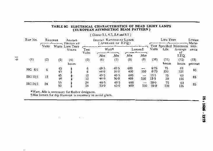
TABLE 3C HEAD LIGHT LAMPS ( EUROPEAN ASYMMETRIC BEAM PATTERN )
( Clauses 3.1 and 4.1.1 )
fz 18?0.4,
I I
FOCUS FOR HEAD LIGHT FILAMENT
+-- 50 max. -t 32 max+
REF No. VOLT WATT DIAMETER, OVER- LENGTH Max ALL FLANQE
LENGTH, TO LUG, MllX Ma.%
(1) (2) (3) (4) (5) (6)
HC 6/l 6 45/40 41 82 32
HC 12/l 12 45/40 41 82 32
HC 24/l 24 55/50 41 82 32
NOTE - 35 mm oblong shape is also allowed.
LIGHT CENTRE CAP LENCVJZH
(7) (8)
28.5 f 0.35 P 45t
28.5 f 0.35 P 45t
28.5 f O-35 P 45t
12

TABLE 4 FESTOON LAMPS
( Clauses 3.1 and 4.1.1 )
h
REF No. c W
(1)
VOLTS WATT
F 6/l
F 6/Z
F 6/3
F S/4
(2) (3)
6 3
6 5
6 10
6 18
DIAMETER, Max
(4)
9
11
15.5
15.5
F 12/l 12 3 9
F 1212 12 5 11
F 1213 12 10 15.5
F 12/4 12 18 15.5
F 24/l 24 5 11
F2 F3
CAP
(5)
S?
SV 8.5
SV 8.5
CV 8.5
REF TO FIG.
(6)
Fl
F2
F3
F3
S7 Fl SV 8.5 F2 SV 8.5 F3 SV 8.5 F3 SV 8.5 F2
NOTE - The length of the lamps is measured between the positions of the caps at which the diameter is 3.5 mm. 7

IS : 1606 - 1939
TABLE 5 LAMPS USED FOR FOG LIGHTS
( &uses 3.1 and 4.1.1 )
REF No. VOLTS WATTS DIAMETER, OVERALL LENGTH LIGHT CAP Max LENGTH PIN TO CENTRJ~
SOLDER, LENGTH Max
(1) (2) (3) (4) (5) (6) (7) (8)
FOI 12 35 36 66.5 16.5 30 f 0.15 BA20S
F 02 12 50 29 64.0 16*0&2 21.5 & 0.15 P 36s
14

TABLE 6 ELECTRICAL CHARACTERISTICS OF MINIATURE LAMPS ( SIDE, TAIL AND DASH BOARD LAMPS )
REF No. RATINGS AQEINQ
( Clauses 3.1,4.2, 8.4 and 8.5 )
INITIAL RATINGS OF LAMPS
(1) (2) (3)
M 6/l 6 0.6
M 6/2 6 2 w M 6/3 6 4
VI M 614 6 5
M 6/5 6 10
M 12/l 12 1.2
M 12/2 12 2 M 12/3 12 4
M 1214 12 5
M 12/5 12 10
M 24/l 24 2
M 2412 24 4
M 24/3 24 5 M 2 l/4 24 10
r--*--y PERIOD AT ( AVERAGE OF RTQ ) Volts Watts LIFE TEST r-------- h_----___y
VOLTS Test Volts
Watt ~_~~h~_~~
Max Min
(6) (7)
0.7 0.5
2.3 1.7
44 3.6
5.5 4.5
11 9
1.4 1.0
2.3 1.7
44 3.6
5.5 4.5
11 9
3.45 2.55
5.5 4.5
7.7 6.3
13.75 11.25
Lumen; Min
(4) hours
t”
tt
:
: a t
:
(5) (8) (9)
6.75 6.75
6.75 6.75 6.75
13.5 13.5 13.5 13.5 13.5 28.0 28.0 28.0 28.0
2.5 6.75
8.75 6.75 28 6.75 40 6.75
100 6.75
7.7 13.50
7.5 13.50
28 1350
40 18.50
100 13.50
11.9 28
28 28
40 28
100 28
LIFE TEST LUMEN ~~~~_h~~~~~~ MAIN- Test Specified Minimum TEN- Volts Life Average of ANCE
LTQ
(10) (11) hours hours
200 156
200 156 200 156 200 156 200 156 200 156 200 156 200 156 200 156 200 156 200 156 200 156 200 156 200 156
(12) percent
85
85
85
85
85
85
85
85
85
85
85
85
85 5:
85 . .

TABLE 7 ELECTRICAL CHARACTERISTICS OF MEDIUM LAMPS ( INTERIOR, STOP-AND-TAIL AND FLASHER LAMPS )
( Clauses 3.1, 4.2,8.4 and 8.5 ) REB No. RATINGS AC~EING INITIAL RATINQS OF LAMPS LIFE TEST LUMEN
P--- Volts
-7 PERlOD AT ( AVERAGE OF RTQ) r___~__---~ MAIN-
Watts LIFE TEST r----___h ___- --.---, Test Specified Minimum TEN- VOLTS Test Watt Lumen, Volts Life AVerage ANCE
volts (------L.----j Min of LTQ. Max Min
(1) (2) (3) (4) (5) (6) (7) (8) (9) (10) (11) cw CI hours hours hours percent a D S/l 6 21 d 6.75 27.56 24.44 400 6.75 100 85 85
D 6/Z 6 2: : 6’75 .
2;; 5.4 4% 6.75 1000 850 6.75 24.44 6.75 100 a5 ii; D 613 6 3 tf 6.75 4.0 3-Z 20 6.75 1000 850 85
15 6.75 16.5 13.5 270 6.75 100 a5 85 D 12/l 12 21 f 13’5 26.5 23.5 400 13.5 100 85 85
D 12/Z 12 2; a 13.5 266.65 5.4 30 13-5 1000 85 85 f 13-5 23.5 400 13’5 100 85 a5
D 24/l 24 21 d 28.0 29.68 26.32 400 28 100 85 85
D 85
2412 24 2; a 28.0 i 28.0 li.68 269.32 4% ii 1000
100 iz 85

TABLE 8A ELECTRICAL CHARACTERISTICS OF HEAD LIGHT LAMPS ( BRITISH PREFOCUS BEAM PATTERN )
(Clauccs 3.1, 4.2, 8.4 and8.5)
REE No. RATINQS AGEIS Q INITIAL RATINQS OF LAMPS LIFE TEST LUMEN r--A--~ PERIOD AT ( AVERAGE OB RTQ) y--------h---- MAIN_
Volts Watts LIFE TEST r------~t- A-----------T Test Specified Minimum TENA- VOLT8 Test LUMEN* Volts Life NCE
Volts Average
z
y--/-G; r--A---7 Min MUX
of LTQ
(1) (2) (3) (4) (5) (6) (7) (8) (9) (If-J) (11) (12) (13)
hours hours hours percent
HA 6/l 6 30 t 6.3 35 29.6 472 442 7 50 42 85 24 t 6.3 28 23.6 359 7 50 42 85
HA 12/l 12 50 13.2 62.7 53.1 892 63 85 40 13’2 50.1 42.3 670
827 :t 1;; a5 85
HA2411 24 74 74.1 62.7 1 101 947 ;: 125 100 85 60.3 50.8 763 150 120 85
*MUX lumen for dip filament is necessary to avoid glare.

TABLE 8B ELECTRICAL CHARACTERISTICS OF HEAD LIGHT LAMPS c
( EUROPEAN SYMMETRIC BEAM PATTERN ) 2
( Clauses3.1, 4.2, 8.4 and 8.5)
REF No. RATINGS AGEING INITIAL RATINGS OF LAMPS LIFE TEST LUMEN r-- A--y PERIOD AT Volts
( AVERAQE OF RTQ) ~_~~~~ ----7 MAIN- Watts LIFE TEST ?----- ---h________~ Test TEN-
VOLTS Test Watt Lumen* Volts Specified Minimum
Life Volts
Average ANCE r---- MO% *-- z---- Min Max
of LTQ
(1) (2) (3) (4) (5) (6) (7) (8) (9) (10) (11) (12) (13) I hours hours hours percent cm
HB 6/l 6 15 6.75 16.35 13.65 180 190 6.75 100 85 85 15 6.75 16.35 13.65 180 190 6.75 100 85 85
HB 6/2 6 zz 6.75 26.5 23.5 350 375 6.75 100 6.75 26.5 23.5 250 375 6.75 100 “8: 85
HB 12/l 12 50 13.5 26.5 23.5 350 40 13.5 26.5 23.5 250 375
13.5 100 85 13.5 100 85 85
HB 12/2 12 :z : 13.5 38’5 31.5 520 - 13.5 100 85 13.5 38.5 31.5 375 560 13.5 100 85 85
HB 24/l 24 55 - 28.0 50.7 343 665 700 28’0 100 50
85 - 28.0 50.7 34.3 470 700 28.0 100 85 85
*Max lumen for dip filament is necessary to avoid glare.
-
TABLE 8C ELECTRICAL CHARACTERISTICS OF HEAD LIGHT LAMPS (EUROPEAN ASYMMETRIC BEAM PATTERN )
( Clauses 3.1, 4.2, a.4 and 8.5 )
REF No. RATINQS AGEINCJ IXITIAL RATINGS OF LAMPS LIFE TEST LUIVIEN r---h----, PERIOD AT ( AVERAGE OF RTQ) ~~~~~~* -----7 MAIN-
Volts Watts LIFE TEST r--------- A--------7 Test Specified Minimum TEN- VOLTS Test watt* Lumen* Volts Life Average ANCE
Volts ~~~h~~~ r__h__~ MOX Min Min Max Lo:Q
\3 (1) (2) (3) (4) (5) (6) (7) (8) (9) (10) (‘1) (‘2) (13)
hours hours hours percent
HC 6/l 6 45 s 49.5 40.5 600 - 6.75 75 63 4.5 44.0 36.0 400 550 6.75 150 126 a5
HC 12/l 12 45 12 49.5 40.5 600 550 13.5 75 63 40 12 44.0 36.0 400 13.5 50 126
a5
HC 24/l 24 55 f 24 60.5 49’5 600 - 28.0 75 50 24 55’0 45.0 400 550 28.0 150 1:: a5
*Watt, Min is necessary for flasher designers. tMax lumen for dip filament is necessary to avoid glare.

TABLE 9 ELEdTRICAL CHARACTERISTICS OF FESTOON LAMPS = o&
( Clauses 3.1, 4.2, 8.4 and 8.5 ) Y
REF No. RAT~NQS AQEING INITIAL RATINGS OF LAMPS LIFE TEST r------, PERIOD OF ( AVERAGE OF RTQ) _-_-..-h-_-.~
LUMEN 8 MAIN- ,
Volts Watts LIFE TEST ~~_~~~~_*~~~____~ Test Specified Minimum TENA- VOLTS Test Watt* Lumen Volts Life Average NCE z
Volts r----h- of LTQ is Alax Max Maw
(1) (2) (31
F6/1 6 3
F 612 6 5 F 6/3 6 10 F 6/4 6 18
F 12/l 12 3 F 1212 12 5 F 12/3 12 10 F 12/4 12 18 F 24/l 24 5
(4) hours
t’
d d”
a d- t”
(5)
6.75
6.75 6.75 6’75
13.5 13.5 13.5 :8” 5
~6) (7) (8) (9)
3-9 3.2 22 6.75 5.5 4.5 36 6.75
11 9 100 6.75
23.7 19.3 200 6.75
3.9 3.2 24 13.5 5.5 4.5 36 13.5
11 9 100 13.5 23,7 19.3 200 135 7.7 6.3 36 28
(19) (11) (12)
hours hours percent
200 156 85 200 156 85 200 156 85
200 156 85
200 156 85 260 156 85 200 156 85 200 156 85 200 156 85
TABLE 10 LAMPS USED FOR FOG LIGHTS ( Clauses 3.1, 4.2, 8.4 and 8.5 )
REB No. RATINQS AQEINC INITIALS RATINQS OF LAMPS LIFE TEST LUMEN ,---h--7 PERIOD AT ( AVERADE OF RTQ) ---- ----T MAIN-
Volts Watts LIFE TEST ~--~~----*~~~-~--~ Test Specified Minimum TEN- VOLTS Test watts Lumen Volts Life Averare ANCE
Volts rMT--~
of LTQ Min Mill
(1) (2) (3) (4) (5) (6) (7) (8) (9) (10) (11) (12) hours hours hours percent
FO 1 12 35 13.5 38.5 31.5 685 11.5 100 85 85 FO 2 12 50 13.2 61-O 50.0 1 150 14 75 63 85
t

lS:1606-1979
4.1.5 Solder -The solder shall be so applied as not to interfere with proper engagement in the holder and to ensure satisfactory electrical contact.
NOTE - It is not essential that the whole surface of the eyelet should be covered with the solder, provided there is good electrical contact between the lend-in wire and the eyelet, and the soldering is done without the wire end being visible.
4.1.6 In the case of prefocus lamps, the main filament shall be connec- ted to the contact which is ‘nearer to the slot of the ring. In the case of BA 20d cap lamps, the main filament shall be connected to the left-hand side of the contact when the cap is viewed from below with the bigger pin at the bottom. In the case of BAY 15d cap lamps the low wattage filament shall be connected to the right-hand contact when viewed with cap towards observer, index pin down and low wattage filament uppermost.
4.1.7 Physical measurements and positioning of filament should tally with those shown in the respective figures.
NOTE - A recommended method for checking the appropriate position of the lamp filament in the case of double filament prefocus lamps with or without shield, when tested in accordance with a screen projection method is described in Appendix B. Any other alternative method as agreed between the supplier and the purchaser can also be used for these measurements.
4.2 Initial Rating Requirements - The average initial ratings of the RTQ, namely, initial watts and initial lumens, shall be in accordance with those specified in the relevant tables (see Tables 6 to 10 ) when measured at test voltages specified therein.
4.2.1 Initial photometric and electrical measurements shall be made after an ageing period as specified in the relevant tables.
4.3 Life Performance Requirements - The life of individual lamp and lumen maintenance of individual lamp at 50 + 5 percent of the specified life shall comply with the requirements of the relevant tables. If a lamp does not comply with individual lumen maintenance at 50 f 5 percent life, it shall be considered to have failed at 46 percent life ( see %‘ables 6 to-10 ).
4.4 Vibration Requirements -
5. MARKING
5.1 Each lamp shall be distinctly
(see 7.5).
and indelibly marked with the follow- ing:
a)
b)
Mark of origin ( the mark of origin may take the form of a trade- mark or manufacturer’s name of the responsible vendor );
Rated voltage;
21

1s : 1606 - 1979
4 4
e)
5.1.1
Rated wattage;
Type ( reference No. ). This may be alternatively done on the carton used for packing the lamp; and
Country of manufacture ( this marking may be alternatively done on the carton used for packing the lamps ).
Ldmps may also be marked with the Standard h/lark,
NOTE - The use of the Standard Mark is governed by the provisions of the Bureau of Indian Standards Act, 1956 and the Rules and Regulations made there_ under. The Standard Mark on products covered by an Indian Standard conveys
the assurance that they have been produced to comply with the requirements of that standard under a well defined system of inspection, testing and quality control which is devised and supervised by BIS and operated by the producer. Standard marked products are also continuously checked by BIS for conformity to that standard as a further safeguard. Details of conditions under which a licence for the use of the Standard Mark may be granted to manufacturers or producers may be obtained from the Bureau of Indian Standards.
6. SELECTION OF LAMPS FOR TESTS ( SAMPLING)
6.1 Samples for testing shall be selected from lamps belonging to one batch.
6.1.1 Butch Consisting of 1000 Lamps or Less - For batches consisting of 10 or less containers, lamps shall be selected from every container. If a batch consists of more than 10 containers, lamps shall be selected from at least one-half of the total number of containers in the batch with a minimum of 10 containers.
6.1.2 Bajch Consisting of More Than 1000 Lamps - Lamps shall be selected, as far as possible, from one-third of the total number of con- tainers in the batch, with a minimum of 10 containers.
6.2 Inspection Test Quantity (ITQ) - Inspection test quantity shall consist of 30 lamps for single filament lamp.
6.3 Rating Test Quantity ( RTQ) - Rating test quantity shall be selected from lamps which have passed the inspection test and shall consist of 25 lamps for single filament lamps.
6.4 Life Test Quantity ( LTQ) - Life test quantity shall be sele-ted from lamps which have passed the initial rating test and shall com’st of 10 lamps for single filament lamps.
6.5 Vibration Test Quantity (VTQ) - The vibration test quantity shall be selected from lamps which have passed the initial rating tests and shall be subject to the agreement between the purchaser and the supplier.
6.6 In the case of double filament lamps, the above scale of sampling ( 6.2 to 6.5 ) shall apply to each filament separately.
22

iS : 1606 - 1979
7.1 Conditions for Testing
7.1.1 Position ofBurning - For the purpose of the test for initial readings, the lamps shall burn in the vertical position, cap up. In the case of festoon lamps they shall burn in a horizontal position. For life tests and ageing, they shall be burnt horizontally. In the case of lamps for head- light, the plane of the pain filament shall also be horizontal during the life and vibration tests.
7.1.2 Ageing - Before the initial readings are taken, the lamps shall be aged for a period mentioned in the relevant table at the voltage specified therein.
7.1.3 Photometcv - Readings shall be taken with a suitable photome- tric integrator ( see also IS : 2407-1963* ) at the voltage specified in the relevant table.
7.2 Visual Examination and Checking for Mechanical and Physi- cal Requirements - Each lamp of ITQshall be examined visually as well as checked for physical and mechanical requirements detailed in 4.1 and marking requirements specified in 5.
7.2.1 Torsion Test - Lamps sha’ll be inserted in a special holder which should be fixed to a suitable torsion testing machine. The test shall then be carried out by twisting the bulb. The torques shall not be applied suddenly but increased gradually to the moment specified in 4.1.4.
7.2.2 In the case of double filament lamps, separate ITQ, as provided for, shall be used for inspection tests on each filament.
7.3 Initial Rating Test - Measurements shall be made for initial watts and initial lumens at the test voltage specified in the relevant table with an integrating photometer. The voltmeter and ammeter, when used for rhe test, shall have a class index 0.5 or better ( see IS : 1248-19681_ nnd IS : 732-1963$ ).
7.3.1 In the case of double filament lamps, separate RTQ’s, as provided for, shall be used for rating tests on each filament.
7.4 Life Test - The lamps selected for the life test shall burn throughout life in the normal burning position at the specified test voltage given in the relevant table.
*Specification for photometric integrators. tSp.ecifk tion for direct acting electrical indicating instruments. $Code of practice for electrical wiring installations (system voltage not exceeding
650 volts ) ( revised ).
23

L. .“.. , -- -“-. ” “__.
f$ : 1606 - 1939
In the case of double filament lamps separate LTQ’s, as provided for, shall be used for life test on each filament.
The voltage shall be ac at 50 Hz and kept within f 1.0 V during the life test.
In the case of double filament lamps, the position of filament shall be similar to that used in actual practice.
7.4.1 Voltage Control - The m’omentary fluctuations of the test voltage during the life test shall not exceed f 1 percent.
7.4.2 Switching On and Off During Life Test - Lamps on life test shall be switched off twice in 24 hours of operation for a period of not less than 15 minutes, such periods not being considered as part of the life of the lamp.
7.4.3 Accidentally Broken Lamps - If one or more lamps break acciden- tally in handling during life test, the life test results may be computed on the basis of results obtained on the remainder of the LTQ, provided the number of the latter is not less than 9.
7.4.4 Measurements During L$ Test ( E$ciency Maintenance ) - Each lamp of the LTQ shall be tested for lumens with an integrating photo- meter at the test voltage at 50 & 5 percent of the specified life.
7.4.5 Duration of Life Test - For the purpose of computing average life of LTQ, lamps operating beyond 125 percent of the specified life in the life test shall be deemed to have a life equal to 125 percent of the speci- fied life only.
7.5 Vibration Test - The test procedure and parameters to be checked shall be subject to agreement between the purchaser and the supplier ( see also 0.7,). 8. CONDITIONS OF COMPLIANCE
8.1 General - If any test quantity fails to satisfy any of the requirements of 8.2, 8.3, 8.4 and 8.5 the batch shall be rejected and no subsequent tests shall be carried out from the batch. 8.2 Selection of Lamps for Tests - Samples for testing shall be selec- ted at random from lamps belonging to one batch and shall be as speci- fied in 6.1. 8.3 Mechanical and Physical Requirements and Marking - The number of lamps failing shall not exceed the following qualifying limit for compliance:
For any single clause ( 4.1.1 to 4.1.7 and 5) For all clauses together
24
Qualifying Limit
2
3
IS : 1606 - 1979
8.4 Initial Ratings - A batch shall be considered to comply with the initial rating requirements ( see 4.2 ) if the following conditions are comp- lied with:
a) The average wattage of the RTQ shall not fall outside the minimum and maximum values given in the relevant tables ( see Tables 6 to 10 ).
b) The average lumens of the RTQ shall not be less than the minimum for compliance given in the relevant table (see Tables 6 to 10).
3.5 Life Performance - The batch shall be considered as complying with life performance requirements ( see 4.3 ) if:
a) The minimum average life of the LTQ shall not be less than the minimum life specified in the relevant tables (see Tables 6 to 10).
NOTE - These figures are lower than the specified life in order to cover the statistical uncertainty involved in testing small samples.
b) The number of lamps of the LTQhaving lives less than 60 percent of the specified life together with the lamps having lumen main- tenance at 50 percent of the specified life less the value specified in the relevant table ( see Tables 6 to 10 ) shall not exceed the compliance number given below:
Test Quantip Compliance Ovum ber
10 For Group I and IV 4 For Group II, III and V 2
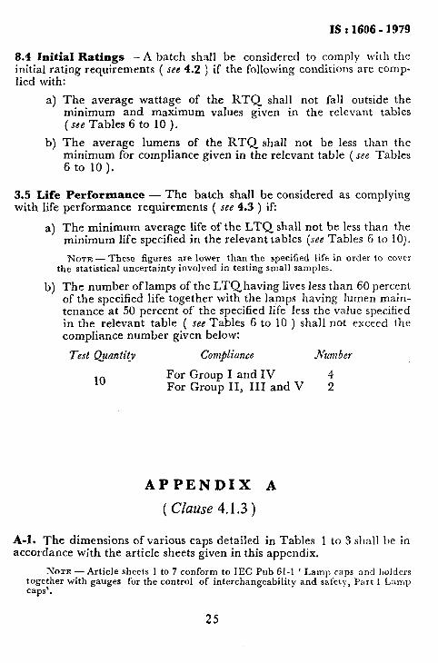
APPENDIX A
( Clause 4.1.3 )
A-l. The dimensions of various caps detailed in Tables 1 to 3 shall be in accordance with the article sheets given in this appendix.
NOTE -Article sheets 1 to 7 conform to IEC Pub 61-1 ‘ Lamp caps and holders together with gauges for the control of interchangeability and safety, Part I Lamp caps’.
25

mh... .‘ _ ., ___ __
Article Sheet No. 1 BAYONET AUTOMOBILE CAPS
BA 7
Dimensions in millimetres. The drawings are intended only to indicate the dimensions to be controlled.
Zaps may be made with a flare* the diameter of which shall not be more than 1.5 mm greater than the maximum permissible diameter of the corresponding cap without a flare.
WITH SOLDER
DIMEN- UNMOUNTED CAPSON 8ION CAP%+ FINISHEDLANPS *These dimensions are solely for cap
r__h__~ r-__h__T design and are not to be gauged on the Min MU Min MO% finished lamp.
A (2) 6.87 7.05 (3) 6.87 ‘.I0 (3) +The values shown below are solely for c 0.90 cap design and are not to be gauged, D 7.7 8-1 : : unless specified otherwise.
Dl - 1) This dimension is checked with a E
b:“, millimetre scale.
F 2) Dimension jV denotes the minimum 3.4 length over which dimension A shall 2.4 conform; below this length, dimension A
Jv (2) 2.6 - 2’6 - maximum shall not be exceeded. CI Approx : 30° Approx: 30”
IEC Ref No, 7004-15-2
26

Article Sheet No. 2
BAYONET AUTOMOBJLE CAPS
BA 9
Dimensions in millimetres.
The drawings are intended only to indicate the dimensions to be controlled.
WITHOUT SOLDER
Caps may be made with a flare* the dia- meter of which shall be not more than 0.5 mm greater than the maximum permissible diameter of the corresponding cap without a flare.
WITH SOLDER
DIMEN- UNMOUNTED CAPS ON *These dimensions are solely for cap SION CAPS? FINISHED LAMPS design and are not to be gauged on the
r---h-_~ T_-A___, Min
finished lamp. MU Min MO% tThe values shown below are solely for
A (2) 9.08 9-20 9.08 9.25 10.11
cap design and are not to be gauged, 9,75 IO.16 unless specified otherwise. - - 1) This dimension is checked with a
millimetre scale. 2) Dimension N denotes the minimum
length over which‘dimension A shall con- form; below this length, dimension A Max shall not be exceeded.
Y21 4.5 4’5 3) The radius of the edge of the rele-
- IO.95 - Go vant pin shall not exceed 0.2 mm when dimension B is at the minimum value of 9.75 mm. If dimension B exceeds 9.75 mm, the radius may be increased accordingly. This requirement applies only to the half of the edge adjacent to the bulb.
IEC Ref No. 7004-14-6
27

Article Sheet No. 3
SCREW CAPS E 10
Dimensions in millimetres.
The drawings are intended only to indicate the dimensions to be controlled.
Caps may be made with a flare+ the diameter of which shall be not more than 1 mm greater than the maximum permissible diameter of the corsesponding cap without a flare.
For finished lamps the creepage distance over 2 mm.
insulation shall be not less than
RIGHT HAND THREAD
DIMENSIoN
E IO/13 r--*-_-T
Min MLIX *These dimensions are solely for cap design and are not to be gauged on the finished lamp.
1) This dimension is checked with a millimetre scale.
2) ‘T’ is the distance from the contact plate of the cap to the completion of the thread.
IEC Ref No. 7004-22-5
28

IS:1606 - 1979
Article Sheet No. 4
BAYONET AUTOMOBILE CAPS
BA 15
Dimensions in millimetres. The drawings are intended only to indicate the dimensions to bc controllrd.
AS REQUIRED
Recommended length 1750 f 0.25. 19.00 & 0.25 and 21.00 f O-25’
Zaps may be made with a flare* the diameter of which shall be not more than 1 mm greater than the maximum permissible diameter of the corresponding cap without 3 flare.
All other relevant dimensions asforBA15d
BA 15s
Oval Contacts
BA 15d
Circular Contacts
( Continued )
29

ts : 1606 - 1979
Article Sheet No. 4 - Contd
)IMEN- UNMOUNTED CAPS ON CAPS*
*These dimensions/values are solely for SION FINISHRD LAMPS cap design and are not to be gauged on
r- -h--~ c-_*- Min Max Mifr
-7 the finished lamp.
A (1) 15.05 15’25 15.05 *YZl 1) Dimension N denotes the mini-
; (2) 15.65 16’10 15.65 16.15 mum length over which both the mini-
D ;:“o 6.6 1 r mum and the maximum limits of dimen- sion A shall be observed. Below dimen-
2
- 632 . 1.8 2; 1.8 3.;
sion N only the limits for dimension A maximum apply.
E(2) 0.64 - 0.64 - Compliance with the requirements regar- Approx: 9 4.5 5.2 - - -
ding dimension A maximum shall be
H1 checked only with the relevant gauge.
H2 ;:; z $ r The requirements regarding dimension A
$ minimum are as follows:
1.7 a) In every horizontal plane within
K:
8:O 1 1 ;:: 7.1 - -
dimension N, there shall be at least one direction in which the
N(1) 8-Y - 8’9 170
diameter is 15.05 mm or greater. P 16.95 - b) In no direction in any plane 0 Nom 90’ within dimension N shall the
diameter be less than 14.92 mm.
Compliance with these requirements shall be checked with a suitable caliper meas uring device having flat anvils 3 mm wide and a measuring accuracy of + 0.0 - 0.01 mm. The points of measuremeni shall extend from a plane 0.5 mm above the pins up to the minimum value 01 dimension N.
2) The radius of the edge of the rele vant pin shall not exceed 0.2 mm wher dimension B is at the minimum value o 15.65 mm. If dimension B exceeds 15.61 mm the radius may be increared actor dingly. This requirement applies only t the half of the edge adjacent to the bulb
IEC Ref No. 7004-l l A-7
30
- - - . ..-‘.-..- - -
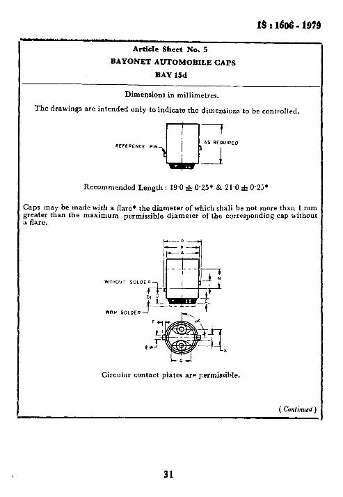
Article Sheet No. 5
BAYONET AUTOMOBILE CAPS
BAY 15d
Dimensions in millimetres.
The drawings are intended only to indicate the dimensions to be controlled.
Recommended Length : 19.0 f 0*25* & 21.0 f 0.25*
Caps may be made with a flare* the diameter of which shall be not more than 1 mm greater than the maximum permissible diameter of the corresponding cap without a flare.
WlTH SOLDER
Circular contact plates are Fermissible.
( Continued )
31

9s : 1606 - i976
Article Sheet No. 5 - Contd
~IMEN- USMOUNTED
Min MIIX A (1)
SION
15.05
CAPS*
15.25 ; (2)
r__h-_7
15.65 16.10
:. ;:“o - 6:6 - E- . 2.2 “G (2) Z4 -
:
Approx: 9
4.5 3.0 - - Jz 1.7
2s 7.0 6.5 8:O 7.1 L. 3.0 3.4
Min
CAPS ON
Max 15.05
FINISEED LAMPS
15.30 15.65
r------3
16.15 - -
6.32 F-5 1.8 2.2 0.64 -
-
F(l) 8.g - IF95 CL Nom. 90"
- - - - - - -
Go 3; 8.9 - - 17.0
-
*These dimensions/values are solely for cap design and are not to be gauged on the finished lamp.
1) Dimension JV denotes the mini- mum length over which both the minimun and the maximum limits of dimension A shall be observed. Below dimension N only the limits for dimension A maximum apply.
Compliance with the requirements regarding dimension A maximum shall be checked only with the relevant gauge.
The requirements regarding dimen- sion A minimum are as follows:
a) In every horizontal plane within dimension .N, there shall be at least one direction in which the diameter is 15’05 mm or greater.
b) In no direction in any plane with- in dimension N shall the diameter be less than 14.92 mm.
2) The radiusof the edge of the rele- vant pin shall not exceed 0.2 mm when dimension B is at the minimum value of 15’65 mm. If dimension B exceeds 15.65 mm, the radius may be increased accor- dingly. This requirement applies only to the half of the edge adjacent to the bulb.
IEC Ref No. ,7004-llB-6

1s I 1696 - 1979
Article Sheet No. 6
-
BAYONET AUTOMOBILE CAPS
BA 20
Dimensions in millimetres.
The drawings are intended only to indicate the dimensions to be controlled.
7 20.00f 00:;;
I+
OUT SOLDER r
-7
%p
AS REOUIREO
-__l
WITH SOLDER
A deviation of O-15 mm either side between the centre line of the small lug and the cerrtre line through the reference lug and the cap centre is permitted. It is checked by the relevant gauge.
DIMENSION Min Max A 19.95 20.1
*These dimensions are solely for cap
g (3)
1.5 design andare not to be gauged on the
15.5 16.0* finished lamp:
L’l e-4
17.0 1) This dimension is checked with a
2s
millimetre scale.
2.9 ;:; 2) ‘8’ denotes the minimum length F 1.9 2.2 to which dimension A shall conform. G (II Approx : 12
T,‘:; 34:; 5.2
3) A deviation in height between the two lugs off 0.15 mm is permitted. It is
- K 9.5* 10.0’
checked by the relevant gauge.
M
.N (2) 50:; -
r c( 82”30’ 9F32or
IEC Ref No. 7004-12-5
33

IrS : 1606 - 1939
Article Sheet No. 7
PREFOCUS CAPS
P 36
Dimensions in millimetres.
The drawings are intended only to indicate the dimensions to be controlled.
ASSEMBLY POSITION OF COLLAR ON FINISHED LAMP
‘m&fled the flange is correctly placed it is permitted to assemble the colloars hat the lip faces towards the base of the cap.
)IMENSI~N Min Max A
*z*
The assembly of the collar to the caF
C 22.10’ shall be such that the recess is in the lint
C(I) . 10.0 with the plane of the two contacts withir
H (1) f 15”.
JK!l) 490 Approx : 10 *These dimensions are soiely for cay
- 10-o* 11.3*
design and are not to be gauged on the
M 20.5* finished lamp.
21 5* P
1) ‘These dimensions are checked wit
: 2325:;: ‘jl,.P’
a millimetre scale.
Approx : 2*5* 0.74 0.84
Approx : 0.51
342.; 2.75
345
IEC Ref No. 7004-49-3
34

APPENDIX B C Clause 4.1.7 )
SCREEN PROJECTION REQUIREMGNTS FOR PREFOCUS
LAMPS ( DOUBLE FILAMENT WITH AND WITHOUT SHIELD )
B-O. This test is used to determine whether a lamp complies with the requirments of 4.1.7 by checking whether the main beam filament is:
a) correctly positioned relative to the major axis of the cap flange; and
b) has a light centre length within the specified limits, whether the dipped beam filament is correctly located relative to the main beam filament and whether the shield is correctly located relative to the dipped beam filament.
B-l. TEST SCREENS
B-l.1 Magnified targets are drawn with the proportions of the permitted tolerances given in Fig. 1, 2 and 3 on test screens which are divided into two parts:
a) A fixed screen on to which the side and front elevations of the main beam filament assembly are projected.
b) A screen, used to check the position of the dipped beam filament relative to the light centre of the main beam filament, which is movable normally to the main axis of the cap flange and is superimposed on the fixed screen.
B-2. TEST PROCEDURE
B-2.1 Images of the filaments with the same degree of magnification are projected on to the test screens.
B-3. REQUIREMENTS
B-3.1 Side Elevation
a) All Lam@ - The image of the main beam filament shall fall completely within the target area of the fixed screen. The mova- ble screen is then adjusted so that the vertical axis bisects the image of the main beam filament. The image of the dipped beam filament shall fall within the target area.
35

IS : 1606 - 1979
b) Lamps With Shields - The moving screen is adjusted so that the 28” line bisects the ‘image of the dipped filament. The lower end of the shield image shall then fall within the target area, and the flat portion of the shield shall be totally enclosed within any adjacent pair of 80” lines.
MOVING SCREEN
FIXED SCREEN v,
:: AXIS OF
CAP-FLANGE z
0.981
RATINQS DIMENSION, mm r--- -----P-h, -----------7 3 K L M N
6 V 30124 W 2.2 1.9 3.25 2.4 2.7
12 v 50140 w 2.6 2;6 3.0 2.5 3.0
24 V 54144 W 3.25 2.75 3% 3.25 3.75
F;Io. 1 TEST SCREEN : DOUBLE FILAMENT WITH AND WITHOUT SHIELD
B-3.2 Front Elevation
a) 6 V 30/24 W ( vertical dip ) ( see Fig. 2 ). The movable screen is adjusted so that the image of the main beam filament falls symmetrically within the area ABCD. The axis of the main beam filament shall fall within the limits on the fixed screen and the image of the dipped beam filament shall fall within the area EFGH.
36

r--’ -._._. ._.^ -- _
IS t 1606 - 1979
FIXED SCREEN
AXIS OF
MOVING SCREEN
AXIS OF MAIN L.C.L PLANE
--
b)
Frc.2 TEST SCREEN : 6 V 30124 W LAMPS VERTICAL DIP
All other ratings (right-hand drive, left dip ) ( see Fig. 3 ). The image of the main beam filament shall fall completely within the upper and lower limiting lines on the fixed screen. The movable screen is then adjusted so that the image of the main beam fila- ment falls symmetrically within the limiting lines AB and CD.
The vertical axis XY then bisects the filament image and shall fall within the limiting lines EF and GH on the fixed screen. The image of the dipped beam filament shall fall completely within the target area of the movable screen with the end turn ( that nearest the axis of the cap flange ) within the area EFGH.
FIXED SCREEN MOVING SCREEN
CAP-FLAFJGE
A
RATING DIMENSION, mm T__-_-_____---h___--~---___~ P R s l- u V w
12 v 50/40 w 3.25 2.6 2.1 6.75 3-o 2.5 2.35 24 V 54/44 W 3.25 3,25 2.75 6.75 3.75 3.25 2.25
FIG. 3 TEST SCREEN : ALL OTHER RATINGS
37

IS a 1696 - 1979
( Continuedfrom page 2 )
Mem hers Representing
SERI R. BHANDARI Bitoni Lamps Pvt Ltd, Faridabad SHRI R, D. KHA~NA ( Alternate )
SHRI R. S. CHANDHO~E Directorate of Research & Develooment f Vehi- 1
MAJ S. K. DEWAN ( Ahnate ) SHRI P. SHARAN GUPTA SHRI A. C. JAIN
DR S. N. DHINORA (Alternate ) SHRI S. K. MU~HERJEE SHRI VEPA A. MURARI
SHRI K. K. ROEATQI
cles ), Department of Defence Production, Ministry of Defence
Auto Lamps Ltd, Faridabad Miniature Bulb Industries (India ) Pvt Ltd,
Dehra Dun
National Test House, Calcut&+ Association of Indian Automobile Manufacturers,
Bombay Binav Electricals and Appliances Pvt Ltd,
SHRI V. P. RORATQI dalcutta
-_
Pradip Lamp Works, Calcutta SHRI AJIT K. ROHATGI (Alternate)
SHRI N. H. SOHANI Central Institute of Road Transport ( Training & Research ), Pune
SHRI A. B. BHAMARE ( Alternate )
38

BUREAU OF INDIAN STANDARDS
Manak Bhavan, 9 Bahwlur Shah Zafar Marg, NEW DELHI 110002 Telaphonas: 323 0131,323 3375,323 9402 Fax:91 113234062,Sl 113239399, 91 113239382
contlaiLab~M4y:
Plot No. 20/9, Sib IV, Sahibabad Industrbl Area, Sahibabd 201010
RegIonal oMc#:
Tebgrams : klanaksansfha (Common to all Offii)
Tebphona
a-770032
Cemtral : Manak Rhavam, 9 Bahadur Shah afar Marg, NEW DELHI 110002 323 76 17
%astam : 1114 CIT Sdwne VII M, V.I.P. Road, Ma&Ma, CALCUTTA 700054 3378662
&lo&em : SC0 335336, Sector 34-A, CHANDIGARH 160022 603843
Southam : C.I.T. Campus, IV Cross Road, CHENNAI 600113 235 23 15
tWastam : MMakaleya. E9, Bahind Mud, Tabphrme Exhan9a, Andheri (East), 832 92 95 MUMBAI 400093
Branch omces::
Pushpak’. Nurmohamad Shaikh Mug. w, AHMEDABAD 380001 5501348
$Prenya Industrial Area, 1 st Sta90, Bm@om-Tumkur Road, BANGALORE 560058
8394955
Gangotri Compbx. Slh Floor, BhadbhadrRoM, T.T. Na9ar, BHOPAL 462003 55 40 21
Plot No. 6263, Unit VI, Ganga Nagu, BHUVNESHWAR 751001 40 36 27
Ma&athk Suildings, 670 Avinaahl Road, COMBATORE 641037 2mo141
Plat No. 43, Sector 16 A, Mathum Road, FARIDABAD 121001 8-28 88 01
Savitri Complax, 1 ! 6 G.T. Fload, GHMABAD 201001 8-71 1996
53/!5 Ward No.29, R.G. Bwua Road, Slh By-lane, GUWAHAT! 781003 541137
5-8~56C. L.N. Gupta Mug, Nampally SMon Road, HYDERABAD 500001 201083
E-52, Chitarinjan Marg, CSchama, JAIWR 302001 37 29 25
117/418 6, Sarvodaya Na9u. KANPUR 208006 21 6876
Seth Bhawan, 2nd. Floor. Bahind .Laab Cinema, Naval Ki&ore Road, 238923 LUCKNOW 226001
NIT BUiktiig,_Sacond Fkw. Gokulpat Mad@ NAGPUR 440010 52 51 7t
Patliputra Industrial Estate, PATNA 800013 262305
lnstitution of Engineers (India) Buiii 1332 Shhmji Na9ar, FUNE 411005 323635
T.C.No.14/1421,UnivsnityP.O.Pdaym.THlRWANANTHAPURAM695034 621 17
*Sales Office. is at 5 Chowringhw Approach, P.O. Prinoap Street, CALCUTTA 700072
271085
tSabs Ofltcs is at Novelty Chwbers, Grant Road, MUMBAI 400007
$Sales OffIce is at ‘F’.Bbck. Unity Building. Naraehimaraja Squaw, BANGALORE 560002
309 65 28
222 39 71
Prhledat Slmco PrinIlng Press, Delhi. India

AMENDMENT NO. 1 MARCH 1985 TO
IS : 1606 - 1979 SPECIFICATION FOR AUTOMOBILE LAMPS
( Second Revision )
( Page 11, Tuble 3B ) - Substitute the following for the existing
figure:
k 0 36max.j rf=1.6L0.Lr(=5~5~,.5
I I- I T
‘3 2 I IL -6 max. E E? \t ,: 0 2.020.2
PERMISSIBLE MOVEMENT /p=2’30i
CULiR TO THE HOLE’ AND THE MIDDLE LINE THROUGH THE PIN
MEASURED IN SHADE AND AFTER RIGHT MOVEMENT OF THE LAMP TILL IT STRiKES THE BASIC PIN
DIP LIGHT ELEMENT-
‘%EAD’ LIGHT
e l 1.57 rDlAPHRAGM
_OdKET AXIS \DlP CAP
ELEMEN
L -.
f 3
. . .-.
-9 - ”
POSITION OF INCANDESCENT ELEMENl
a = 0’6 f 0’35 e = 32’70 f 0’35
b = 0’2 f. 0’35 g = 0’5 max
c = 0’5 f 0.30 h = 0’5 max
All dimensions in millimetres.
1

( Page 11, Table 3B, RefJV0. HB 12 /I, Colwntz 3 ) - Substitute ‘ 25 ’ for ‘50 ’ 25
40 *
Page 16, Table 7, Ref Jvos. D 12/2 and D 24/Z, Column 11 ) - Substi-
tute ‘ii ‘for ‘ fl”z ’ at both the places.
( Page 18, Table 8B, Ref Jvo. HB 6/l ) - Substitute ‘ \f$’ for ‘ 180 ’ 180
in column 8 and ‘ - ‘fir ‘ 190 ’ in column 9. 190 190
( Page 18, Table 8B, Ref.hfo. HB 612, Column 9 ) - Substitute ‘,$’ for
‘ 375 ’ 375 *
( Page 18, Table 8B, Ref Ah. HB 12/l, Column 3 ) - Substitute ‘ iz ‘for
‘ 50 ’ 40 -
( Puge 18, Table 8B, Ref No. HB 24/l ) - Substitute the following for the existing row:
(11 (2) (3) (4) (5) ~6) (7) (8)
HB 24/l 24 4; - 28’0 49’5 40’5 665 - 28’0 44’0 36.0 470
(9) (‘0) (11) (12) (13)
- 280 100 85 700 28’0 100 85 85
( Page 19, Table 8C, Ref No. HC 6/l, Column 3 ) - Substitute ‘ $ ‘for
L 43 ’ 45’
( Page 19, Table 8C, Ref 3vo. HC 12/l, Column 11 ) - Substitute ’ :,“o’
‘ 75 ’ for 50 .
( Pa.ge 20, Table 9 J - Substitute ( &fin ) for ( Max ’ in the headings of column 7 and 8.
( Page 20, Table 9, Ref Nos. F ,foY ( 23.7 ’ in COhNln 6 and ‘ 16’2 IfOr
614 and F 12/4 ) - Substitute c 19.13 ’ ‘ lg.3 ’ in column 7 at both the places.
( ETDC 23 )
2
Printed at Simco Printin Press. Delhi, India

AMENDMENT NO. 2 DECEMBER 1994 TO
IS 1606 :1979 SPECIFICATION FOR AUTOMOBILE LAMPS
( Second Revision )
(Page 6, clause 3.1 ) - Substitute the following for the existing clause :
‘3.1 The various particulars of automobile lamps covered by the following seven groups are given in Tables 1 to 6:
Group I Automobile lamps such as side, tail, dashboard aud interior lighting lamps ( see Table 1 )
Group II Other types of interior lighting, stop-tail and direction indicator lamps which are bigger thau Group I in size ( see Table 2 )
Group III Lamps for headlights wherein the luminous inteusity, focussing, etc, are important to give required beam pattern ( see Tables 3A, 3B, 3C, 3D and 3E )
Group IV. Festoon lamps ( see Table 4 )
Group V Lamps used for fog and revolving/flashing lights ( see Table 5 )
Group VI Wedge type bulbs (see Table 6)’
(Page 7, clause 3.1.1 ) - Substitute the following for the existing clause:
‘3.1.1 Typical Shapes ofhmps - For easy identification, the typical shapes of various lainps are given in relevant tables.’
(Page 7, chse 4.1.1, line 3)- Delete the words ‘( see Tables 1 to 5 )‘.
(Page 7,,clause 4.1.4 ) - .Substitute the followiug for the existiug clause:
‘4.1.4 Attachment ofCaps to Class Shells - The caps shail be attached to the glass shells so strongly as to withstand torsion test carried out in accordance with 7.2.1 with the followiug torsioual moments both during the inspection test and at the end of the life test:
Types of Cop Torsional Moment Nm
BA7 Under consideration
BA9 0.23 E 10 0.23
BA 1.5 1.15
BAY 15 1.15
Group :

Types of Cap
P 36121 x 22 BA 20 P 15d 25-l
P 15d 25-3 P 30d 10-3
P 43t 38
P 45t 41
Torsional Moment Nm
1.15
1.15 1.15 1.15
1.15
1.15 1.15’

Ret NO.
Volt watt Diameter Max
Overall Length
Max
Pinto CI-OWII Max
LeIigtb Pin to Solder MllX
(1) (4 (3)
M 6/l 6 0.6
M6R 6 1.2
M6r3 6 2.0
M 614 6 4.0
M 615 6 5.0
A B c D
(4) (5) (6) (7) 6.8 20.7 12 8.7
6.8 20.7 12 8.7
8.8 23.9 18.5 5.9
8.8 27.4 21.5 5.9
19.0 37.5 30 7.5
M 616 6 10.0 19.0 37.5 30 7.5
M6i7 6 3.0 8.8 23.9 18.0 5.9
M 6/S 6 3.0 11.7 23.9 18.0 5.9
M 1211 12 1.2 6.8 20.7 12 8.7
M 1212 12 2.0 6.8 20.7 12 8.7
M 1213 12 2.0 8.8 23.9 18 5.9
M 1214 12 4.0 8.8 27.4 21.5 5.9
M 1215 12 5.0 19.0 37.5 30 7.5
M 1216 12 10.0 19.0 37.5 30 7.5
M 1217 .12 3.4 8.8 23.9 18 5.9
M 12/8 12 3.4 11.7 23.9 18.0 5.9
M 1219 12 8.0 19.0 37.5 30 7.5
M 2411 24
M 24i2 24
M 2413 24
2.0
4.0
5.0
10.0
2.0
8.8 23.9 18 5.9
8.8 27.4 21.5 5.9
19.0 37.5 30 7.5
M 241-1 24
M 2-M ?i
19.0 37.5 30 7.5
6.8 20.7 12 8.7
Cap
E
(8) (9)
BA 7s
BA 7s
BA9S
15 *2 BASS
19 * 2 BA 15s
19 f 2 BA 15s
13 -c 2 BA 9S
12.7 f 2 BA9S
BA 7S
BA 7S
BA 9s
15 = 2 BA 9s
19z2 BA 15s
1922 BA 15s
13+ 2 BA 9s
12.7 + 2 BA 9s
19z 2 BA 15s
BA 9s
1522 BA 9s
1922 BA 15s
19T2 BA 15s
BA 7s
Ref to Initial Ratings of Lamps fig. (Average of RTQ)
Test Volts Watt
(10) (11)
MI 6.75
Ml 6.75
M2 6.75
M3 6.75
Md 6.75
Max Min
(14 (13)
0.7 0.5
1.0 0.8
2.3 1.7
4.4 3.6
5.5 4.5
M4 6.75 11.0 9.0
M2 6.75 3.3 2.7
M4 6.75 3.3 2.7
MI 13.5 1.4 1.0
Ml 13.5 2.3 1.7
M2
MZ
M4
M4
M2
M4
M4
13.5
13.5
13.5
13.5
13.5
13.5
13.5
28.0
28.0
28.0
28.0
28.0
2.3 1.7
4.4 3.6
5.5 4.5
11.0 9.0
3.8 3.0
18 3.0
8.8 7.2
M2
M3
MJ
3.5 2.5
5.5 4.5
7.7 6.3
M4
MI
13.8 11.2
3.5 2.5
Lumen
Min
(14)
8
26
37
100
18
18
7
7
26
37
100
17
17
75
12.0
26.0
37.0
100
12.0
(page 8, Table 1) - Substitute th, . c fdlowing for the existing table except for the figures :
Table 1 Miniature Automobile Lamps ( Side, Tail and Dashboard Lamps ) (Clfzusf?s 3.1 anLf4.1.1 )
Life Test Lumen I-,
Test Volts
Specified Life
(h)
Minimum Mainten- Average ante of LTQ (%)
(15) (16) (17)
6.75 200 156
6.75 200 156
6.75 200 156
6.75 200 156
6.75 200 156
6.75
6.75
6.75
13.5
13.5
200
200
200
,200
200
200
200
200
200
200
2cil
200
200
200
200
20b
200
156 85
156 85
156 85
156 85
156 85
13.5
13.5
13.5
13.5
13.5
13.5
13.5
156 85
156 85
156 85
156 85
156 85
156 85
156 85
28
28
28
156 85
156 85
156 85
28
28
156 85
156 85
(18) 85
85
85
85
85
NOTES 1 Lamps with Ref No. M 6’1, M 6’2. M 6.‘7, M 1217 and M 1219 shall be phased out after 30 March 1995 and therefore are not intended for use in new designs.
2 For the dimension A, if agreed behteen the purchaser and the supplier. 7.2 and 9.5 are permissible in place of 6.8 and 8.8 respectively.
3 All dimensions are in milltmetres.
4 Ageing period at test voltage shall he 15 minutes.

(iJ@ge 9, Table 2) - Substitute the following for the existing table except for the figures:
Table 2 Msdiom Lamps ( Interior, Stop-and-Tail and Flasher Lamps ) (Clauses 3.1 and4.1.1)
Ref NO.
VOll watt
(3)
21
5
21
3
15
5
10
5
18
21
5
21
5
10
10
15
10
21
5
18
21
5
21
15
21
Diameter MlZX
Pinto CtWVn
MU
L-ength Pin to Solder Max
Light Centre Length
A B C n E
(4) (5) (6) (7) (8)
26.5 52.5 45 7*0.5 31.8 2 2
26.5 52.5 45 720.5 31:8 * 2
26.5 52.5 720.5 31.8 -+ 2 BAY 15d D2
26.5 52.5 720.5 31.8 2 2 BAY 15d D2
26.5 52.5 7 + 0.5 31.8r2 BAY 15d D2
26.5 52.5
26.5 52.5
7 + 0.5 31.8*2 BAl5s Dt
7 f. 0.5 31.822 BAY 15d D2
26.5 7 -c 0.5 31.8 r 2 BAY 15d D2
26.5
26.5
26.5
7 eo.5 31.8 -L 2 BA 15s Dt
‘7 * 0.5 31.822 BA I’s Dt
7 * 0.5 31.8~2 BA i5d DZ
26.5
26.5
26.5
45
45
45
45
45
45
45
45
45
45
45
45
45
45
7 * 0.5 31.8 t 2 BAY 15d DZ
7 d 0.5 31.8 r 2 BA 15s Dt
7 2 0.5 31.8 t 2 BAY 15d D2
26.5
26.5
52.5
52.5
52.5
52.5
52.5
52.5
52.5
52.5
52.5
7 z 0.5 31.8~2 BA 15s D1
7 f 0.5 31.8 2 2 BA 15d D2
Cap Ref to Initial Ratings of Lamps Fig. (Average of RTQ)
Teit Volts
(9) (10) BA 15s Dl
BAY 15d D2
(11)
6.75
6.75
6.75
6.75
6.75
6.75
6.75
6.75
6.75
MU.% Min Mitt
02) (13) (14)
28 24 370
6.6 5.4 26
28 24 350
4.0 3.2 20
16.5 13.5 180
6.6 5.4 26
11.0 9.0 90
6.6 5.4 26
21.5 19.8 200
13.5
13.5
13.5
13.5
13.5
13.5
13.5
13.5
13.5
13.5
13.5
28
28
28
28
28
26.5 23.5 370
6.6 5.4 26
26.5 23.5 350
6.6 5.4 26
11.0 9.0 90
11.0 9.0 1oD
16.5 13.5 180
11.0 9.0 90
26.5 23.5 350
6.6 5.4 26
19.3 16.2 200
30 26 370
11.0 9.0 26
30 26 350
16.5 13.5 180
30 ‘6 370
Test Volts
Specified Life (h)
Minimum Mainten- Average ante of LTQ @)
(15) (16) (17) (18)
6.15 100 85 85
6.15 loo0 850 85
6.75 100 85 85
6.75 1000 850 85
6.15 100 85 85
6.75 1000 850 85
6.15 100 85 85
6.75 1000 850 85
6.15 100 85 85
13.5
13.5
13.5
13.5
13.5
13.5
13.5
13.5
13.5
13.5
13.5
28
28
28
28
28
100
1000
100
loo0
100
100
100
1000
100
1000
100
100
loo0
100
100
100
85 85
850 85
85 85
850 85
85 85
85 85
85 85
850 85
85 85
850 85
85 85
85 85
850 85
85 85
85 85
85 85
Lumen
(1) (2) D 6/l 6
D6i2 6
D6i3 6
D 614 6
D 615 6
D 12/l 12
D 12i2 12
D 12i-3 12
D 1214 12
D 1215 12
D 1216 12
. D 12i7 12
D 34/l 24
D 2412 24
D 24/3 24
D ‘414 24
NOTES 1 Lamps D 6/2, D 6/4, D 1215, D 12~7 shall be phased out and are not recommended for use in new design after 30 March 1995. 2 Ageing period at test voltage shall be 15 minutes. 3 All dimensions are in millimetres.
4

(Page 10, Table 3A) - Substitute ttie following for the existing table except for the figures:
Table 3A Head fight Lamps ( Anglo American Pattern )
Ref volt was No. ~
(1) (2) (3)
HA6/1 6 30
24
HA 1211 12 50
40
HA 24/l 24 54
44
A B
(4) (5)
29 64
29 64 16*2
29 64 16a2
c D
(6) (7)
1622 21.5 2 0.5
Cap Filament
21.5 + 0.5
21.8 + 0.5
(8) P36
P36
P36
(9)
Drivihg
Passing
Driving
Passing
Driving
Passing
Initial Ratings of Lamps (Average of RTQ)
Test Vok Wart Lumen -e
Max Min Min MCl.X
(10) (11) (12) (13) (14)
6.3 35 29 470 -
6.3 28 23 360 445
13.2 63 53 890 -
13.2 50 42 670 830
28.0 74 62 1100 -
28.0 60 51 760 950
Life Test
Test VOIIS
Specified Life
(h)
Lumen
Minimum Mainten- Average ante of LTQ (%I
(15) (16)
7 50
7 50
14 75
14 100
28 125
28 150
(17) (18) 42 85
‘42 35
63 85
85 85
100 85
120 85
NOTES 1 All dimensions are in millimetres. 2 Ageing period at test voltage shall be 15 minutes for HA6/1 and 30 minutes for other lamps.
3 The lamps HA 6/l, HA 12/l, and HA 24/l shall be phased out and are not recommended for new design after 30 March 1995.

(Page 11, Table 3B, figure ) - Delete values after ‘f ’ from the figure.
( Page 11, Table 3B ) - Substitute the following for the existing table except for the figures:
Table 3B Head Light Lamps ( Symmetric Beam Pattern )
Ref Volt Watt Diametet NO.
(1) (2) (3)
HB 6/l 6 15
15
HB6/2 6 25
25
HB 12/l 12 25
25
HB 1212 12 35
35
HB 24/l 24 45
40
Max OVerall Dimeo- Leogtb sion
Max f
~ng~ Pin to Solder
MaX
Liillt Centre L‘=gth
(4)
36
K) 05) 71 1.8 + 0.6
(7) (8) 17.0 32.7 -c 0.55
36 71 1.8 20.6 17.0 32.7 + 0.55
36 71 1.8 + 0.6 17.0 32.7 * 0.55
36 71 l.St0.6 17.0 32.7 + 0.55
36 71 2.2 2 0.8 17.0 32.7 t 0.55
Cap Filament Initial Ratings of Lamps (Average of RTQ)
(9) (10)
BA 20d Driving
Passing
Test Volts Wan Lumen -- MUX Min Min MUX
Cl!) (12) (13) (14) (15)
6.75 16.5 13.0 180 -
6.75 16.5 13.0 125 190
BA 20d Driving 6.75 26.5 23.5 350 -
Passing 6.75 26.5 23.5 250 375
BA 2Od Driving
Passing
13.5 26.5 23.5 350 _
13.5 26.5 23.5 250 375
BA ‘Od Driving 13.5 38.5 31.5 520 -
Passing 13.5 38.5 31.5 370 560
BA 29d Driving
Passing
28 49.5 40.5 665 -
28 44.0 36.0 470 700
Life Test Lumen
Test Specified Minimum Mainten- Volts Life Average ante
(h) ofLTQ f%)
(16) (17) (18) (19)
6.75 100 85 85
6.75 100 85 85
6.75 100 85 85
6.75 100 85 85
13.5 100 85 85
13.5 100 85 85
13.5 100 85 85
13.5 100 85 85
28 100 85 85
28 100 85 85
NOTES 1 Lamp HB 6/l shall be phased out and hence is not intended to be used in new design after 30 March 199.5.
2 All dimensions are in millimetres.
3 Ageing period at kest voltage shall be 15 minutes.

p,nolle osle s! adeqs %ooJqo mu SE f
3a1my.u og aq lleqs a%qloh pal le popad %u!aQ 2
-sanam!lpu u! ale suo!suaru!p 1~ 1
SILLON
58 9ZI OS1 0’82 OSS OOP O’SP 0’5s PZ au$Tsed
58 E9 SL 0’82 009 s‘6P so9 PZ %wua Wd 8’0 T 2’2 sso z 5’82 Zf 28 IP OSISS PZ IIPZ 3H
58 9ZI OS1 S’EI - oss OOP 0’9f o’w ZI %UmEd
S8 f9 SL SfI 009 S’OP s’6P ZI &l!AUfJ KVd 9’0 i 8‘1 SS’O T SE Zf ZS IP OWSP ZI I/z1 3H
S8 9ZI OS1 SL’9 OSS OOP 0’9f o’w 0’9 %uped
S8 i9 Si SL’9 - 009 S’0t s’6P 0’9 %+a KVd 9’0 = 8’0 SS’O T 5’82 Zf T8 IP OtVSP 9 II9 3H
(61) (81) CL11 (91) (SI) (PI) (El) (ZI) (11) (01) (6) (8) CL) (9) ts1 (P) (f) (z) (1)
XDW C?iJ
U?J4 uw ~~ QL.7 30 00 ‘--
axI8 OtWV a3n w% uauln-J IWM SIlOA IsaL -UwJ!eptJ ru”Io!“!Jq p.xJpds
mfl WL / mSUJ1 ‘%n? 01 XDW
(b.L?l JO ~~WJ) OO!S IlCWll”~
=wQ OzclS~
P?L WI
qgzz *am sdurs7 b Www ppp1
‘ON 1UOuVl da3 -Ilzwl~ Is%!l ¶8Oul w’a”o -sa ll’hi VP‘4 PII

( page 12, Table 3C ) - After Table 3C , insert the following new tables as Tables 3D and 3E :
Table 3D Head Lit Lamps ( Symmetric Beam Pattern )
HEAD LIGHT LAMP HEAD LIGHT LAMP
Reference
c direction
a
UPPER F’T PROJECTION
Reference - Diane
P 30 d-10.3
CAP TO NO. I FILAMENT
/-----
FILAMENT ANGL
9 0’ ,20’ kJ2
HJ 1
8

Table 3D Head Light Lamps ( Symmetric Beam Pattern ) - Concluded
NO.1 FILAMENT (DRf VINQ
.2 FILAMEtjT (PA5SING!
HJ 3 Filamellt Initial Ratings of Lamps Life Test Lumen
(Average of RTQ) -Y
Test Volts Watt
(10) (11)
Driving 6.5
Passing 6.5
M&k Min Min
(1.9 (13) (14)
27.5 22.5 350
27.5 22.5. 350
Driving 6.5 38.5 31.5 570
Passing 6.5 38,s 31.5 570
Driving 6.5 27.5 22.5 370
Passing 6.5 27.5 22.5 370
Driving
Passing
38.5 31.5 580
38.5 31.5 580
Driving
Passing
27.5 23.7 360
27.5 23.7 360
Driving
Passing
13.0
13.0
13.0
13.0
13.0
13.0
16.5 13.5 200
16.5 13.5 200
Ref Volt Watt Din- Overall LnSth L-t@ Pin to
Max Solder Max
B 1)
(5) (6)
60 12
cz bnBth
E
(7) 28.5 f 0.3
Cap Refta
Fk3.
(9)
HI1
HJ1
HJ2
HJl
HJ3
HJ3
NO. meter Specified
Life
(h)
(17)
100
100
100
100
100
100
100
100
100
100
100
100
Test Volts
(16)
6.50
6.50
6.50
6.50
6.50
6.50
13.0
13.0
13.0
13.0
13.0
13.0
Minimum Mainten- Average ante of LTQ (S)
(18)
85
85
85
85
85
85
85
85
85
85
85
85
(19)
70
70
70
70
70
70
70
70
70
70
70
70
Lumen
A
(4)
31
(8) PlSd-25-3
31 60 12 28.5 + 0.3 P15d - 25 - 3
36 60 12 28.5 t 0.3 P3Od - 10.3
31
20
20
60 12 28.5 2 0.3 P15d - 25 - 3
50 12 20 + 0.5 P15d - 25 - 1
50 12
7
20 t 0.5 P15d - 25 - 1
(15)
470
720
470
750
515
260
I (1) (2) (3)
HI611 6 25
25
HJ6R 6 35
35
HJ6/3 6 25
25
HJ 12il 12 35
35
HJ 1212 12 25
25
HJ 1213 15
15 L
N0TE.b 1 Lamps HJ 12/l and HJ 1213 shall be phased out and hence not intended for new design after 30 h4arch 1995. 2 Ageing period at test voltage shall ?x 1.5 minutes.
3 All dimenstions are in millimetres.
4 For the purpose of clause 4.3, the lumen maintenance (%) shall be verified at 75% of the specified life.
9

Table 5E Head Light Lamps (Asymmetric Beam Pattern Halogen) (Clauses 3.1 and 4.1.1)
Ref No.
VOk watt Dia- OveraII meter Length MU Max
I.%$ Pin to Solder
MU
Light Dimension Ceutre Length f
(1) (4 (3) (4) (5) (6) HE 12/l 12 60/55 - 92 32
HC 1212 12 60155 - 92 32
HE 24/l 24 75flo - 92 32
(7) (8) 28.5 L 0.55. 1.7 + 0.5
- 0.45 - 0.3
28.5 + 0.55 1.7 + 0.5
- 0.45 - 0.3
29.0 2 0.60 2.0 2 0.4
HE 2412 24 75/70 - 92 32 29.0 = 0.60 2.0 -+ 0.4
Cap Ref to Fila- Fig.
Initial Ratings of Lamps ment (Average of RTQ)
Life Test Lumen
Test Specified Minimnm Mainten- VOlts Life Average ~IKX
(h) OfLTQ (“/c) Test Volts Wan Lumen
-- MUX Mitl Min Mm
(9) (10) (11) (12) (13) (14) (15) (16) P43t-38 HE1 Driving 12 75 - 1000 1500
Passing 12 68 - 600 900
P451- 41 HE 2 Driving 12 75 - 1000 1500
Passing 12 68 - 600 900
P43r-38 HE1 Driving 24 85 - 1000 ‘1500
Passing 24 81 - 640 960
P451- 41 HE2 Driving 24 85 - 1000 1500
Passing 24 81 - 640 960
07) (18)
13.2 150
13.2 300
13.2 150
13.2 300
28.0 150
28.0 300
28.0 1Sb
28.0 300
(19) (20)
126 85
252 85
126 85
252 85
126 85
252 85
126 85
252 85
NOTES 1 Halogen lamps shall be used only if the headlight assembly complies with IS 3563 : 1974 - Automobile Headlights. 2 Halogen lamps other than these shall be treated as non-standard:
3 HE 12/2 and HE 24/2 shall be phased out and are not intended for use in new design of head lamps after 30 March 1995.
4 All dimensions are in millimetres. 5 Ageiog period at test voltage shall be 30 minutes.
6 For the purpose of clause 4.3, the lumen maintenace (%) shall be verified at 75% of the specified life.
10

AxIs OF BULB I
I-- REFERENCE PLANE
\REFERENCE AXIS
All dimensions in millimetres.
Reference Dimension
e 28.5
Tolerance
t 0.45 - 0.25
Halogen Lamp with P 43 t 38 Cap
HE 1
REFERENCE PLANE I- EARTH PASSING BWI -0 I------
All dimensions in millimetres.
Reference Dimension Tolerance I I
e 28.5 t 0.45 - 0.25
I In 60.0 Max -
n 34.5 Max -
s 45 -
o( 40° Max -
Halogen Lamp with P 45 t 41 Cap
11 HE2
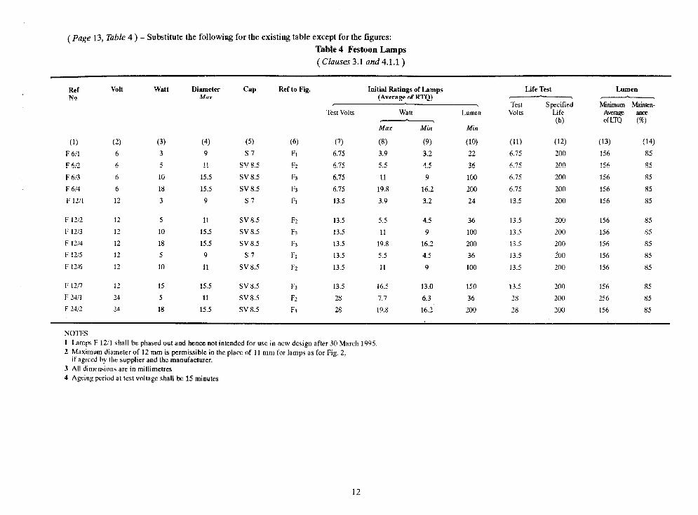
(page 13, Table 4 ) - Substitute the following for the existiug table except for the figures:
Table 4 Festoon Lamps
( Clauses 3.1 and 4.1.1)
Rd NO.
Volt watt
(1) (2) (3)
F 6/l 6 3
F6/2 6 5
F6t3 6 IF
F 6W 6 18
F 1211 12 3
F 1X 12 5
F 1213 I2 10
F 1214 12 18
F 1215 12 5
F 1216 12 10
F 12/l 12 15
F 24/l 24 5
F Xi2 14 18
Diameter MUX
Cap Ref to Fig.
(4) (5) (6)
9 Sl &
11 SV 8.5 F2
15.5 SV 8.5 R
15.5 SV 8.5 F3
9 s7 FI
11 SV 8.5
15.5 SV 8.5
15.5 SV 8.5
9 Sl
11 SV 8.5
15.5 SV 8.5
11 SV 8.5
15.5 SV 8.5
F2
F3
F3
FI
F2
F3
F2
F3
Test Volts
(7)
6.15
6.15
6.75
6.75
13.5
13.5
13.5
13.5
13.5
13.5
13.5
28
28
Initial Ratings of Lamps (Average of RTQ)
Watt
MOX Min
(8) (9)
3.9 3.2
5.5 4.5
11 9
19.8 16.2
3.9 3.2
5.5 4.5
11 9
19.8 16.2
5.5 4.5
11 9
16.5 13.0
7.7 6.3
19.8 16.2
Lumen
Min
(10)
22
36
100
200
24
36
100
200
36
100
150
36
200
Life Test
Test Volts
Specified Life
(h)
(11) (12)
6.75 200
6.75 200
6.75 200
6.75 200
13.5 200
13.5 200
13.5 200
13.5 200
13.5 200
13.5 200
13.5 200
18 200
28 200
LmlMl
Mrdmum
Average - OfLm w
(13) (14)
156 85
156 85
156 85
156 85
156 85
156 85
156 85
156 85
156 85
156 85
156 85
256 85
156 85
NOWIS 1 Lamps F 12/l shall be phased out add hence not intended for use in new design after 30 March 1995
2 Maximum diameter of 12 mm is permissible in the place of 11 mm for lamps as for Fig. 2: if agreed hv the supplier and the inanufatiurer.
3 All dimenkms are in millimetres
4 Ageinp period at test voltage shall be 1.5 minutes.
12

‘=Wl - ( 38 +P!! ‘61 asvd )
*alapa - ( 88 qpL ‘81 aSud)
*was - ( v8 wu ‘f 1 asvd )
wpa - ( L W’!! ‘91 asud )
58 S8
SS f9
58 58
(91) W
001 ox SL O’PI
001 S’II
(PI) (El)
009 O’Zf O’ot O’EI SSI v0 0’15 8’If S’L Z’SS 9f 9f tZ foci
OS11 0’0s 0’19 Z.fI S9f d ss’o 7. S’IZ 0’91 O’P9 6Z OS ZI ZOd
ss9 .SIf S’8f SE1 SOzva sso=o’Of 5’91 S’99 9f Sf ZI IOci
(II) (II) to11 (6) (8) CL) (9) (5) b) 1f) CT) (1)
U?l4 “?lv “W
uaunq 116M SllOA ISJL -Jv
M--l =Plos W4 (&LX JO R’uaW)
SdursI J” asan@x I’!w Jww 01 vd p%aul mkv “N
d63 lSsn lnsuvl IF”0 ,636",6!-, R6M WA JJ2.l

(Page 15, Table 6 ) - Substitute the following fcr the existing table:
Table 6 Wedge Type Lamp
( Clauses 3.1, 4.2, 8.4 and 8.5 )
Ref NO.
(1) w 12/l
w 12/2
w 12l3
w 1214
w 1215
W 2411
W 24t2
w 24r3
Ratings
Volts watts
(2) (3)
12 1.2
12 1.1
12 3.0
12 5
12 18
24 1.2
24 3
24 5
Ref to Cap Fig. No. Size
(4)
w2
Wl
Wl
Wl
w3
w2
Wl
Wl
AghP Period at Lie Test
V0lt.S
(9 (6) W 2 x 4.6D l/4
W 2.1 x 9.5D l/4
W 2.1 x9.5D 114
W 2.1 x9.5D l/4
W 2.1 x 9.5D 114
W 2 x 4.6D l/4
W2.1x9.5D l/4
W2.1x9.5D l/4
Initial Ratings of Lamps (Average of RTQ)
Test Volts Watt Lumen
Maw Mb1 &fin
(7) (8) (9) (10)
13.5 1.4 I.0 6
14.4 2.0 1.5 Y
13.5 3.4 2.6 15
13.5 5.5 4.5 37
12.8 19.8 17.2 1sn
28 1.7 1.3 6
28 4.6 3.4 15
28 7.7 6.3 37
Life Test Lumen
Test Volts
Specified Minimum Life Avem&je
(h) OfLm
(11) (12) (13) (14)
13.5 1000 850 85
14.x 1000 850 85
13.5 1000 850 85
13.5 200 156 85
12.8 200 156 85
28 loo0 850 s:
28 1000 850 85
28 200 156 85
L_cI 8 6.1 MAX -
- & Qj-
-
*Dimension 14.7 f 2.3 for lamps W 12/3 and W 12/S or 12.7 * 1.5 for other lamps, W3
14

(Page 21, &use 4.2, Iine 3 ) Delete the words ‘(see Tables 6 to 10)‘.
(Page 21, clause 4.3, lines 5 and 6 ) - Substitute the words ‘(see Table 6)‘for ‘(see Tables 6 to 10)‘.
( Page 22, clause 6.2 ) - Substitute the following for the existing clause:
‘6.2 The Inspection Test Quality (ITQ) - Inspection test quality shall be as under:
i) In the case ofdouble filameut lamps giveu in Table 3E aud single filament lamps: 30
ii) In the case of other double filament lamps: 60. (Page 22, clause 6.6 ) - Delete.
( Page 23, clause 7.1.2 ) - Add the following at the end:
‘The lamps which fail during the ageing period shall be omitted from the test results.’
(Page 24, clause 7.4, puru 3 ) - Delete.
( Page 24, clause 7.4.1 ) - Substitute the following for the existing clause:
‘7.4;1 Voltage Control - The measurements shall be carried out at the test voltage which shall be a stable ac voltage with frequency between 40 and 60 Hz. The test voltage is deemed to be stable when the momentary fluctuation does uot exceed 1 percent and average over the period does not vary by more thau t 0.1 V from the test voltage.’
(Page 24, chse 7.4.5) - Insert the following new clause as clause 7.4.6:
‘7.4.6 Test Conditions -During the life test, it is preferable to maintain the room temperature at 25 t 2.5”C. If this is uot possible, pdequate care should be taken that heat of one lamp doeshnot disturb the other lamps. This conditiou shall be deemed to be satisfied if a minimum distance of 250 mm is kept between lamps.’
[ Page 2.5, clurrse 8.4 (a) aud (b) ] 7 Delete the words ‘(see Tables 6 to 10)‘at both the places,
( ?%ge ‘25, dame 3.5 ) - Reumnber this clause as 8.5 and substitulc lhc following for the existing clause:
‘8.5 Life Performance - The batch shall be considered as complying with life performance requirements ( see 4.3 ), if:
a) The minimum average life of the LTQ shall not be less than the minimum life specified in the relevant tables. NOTE - These figures are lower than the specified life in order to cover the statistical uncertainty involved in testing small samples.
b) The number of lamps of the LTQ having lives less than 60 percent of the specified life together with the lamps having lumen maintenance at 50 percent of the specified life less the value specified in the relevant table shall uot exceed the compliance number given below:
15

Test Quantiy Compliance Number
For Group I and IV 4
For Other Groups 2
(Page 25, clause A-l) - Insert the following new clause as clause A-2 :
‘A-2 In the case of caps BA 20d, BA 15, BAY 1.5, BA 9 and BA 7, the slot if provided for side solder of wire and soldering shall be such that the tolerance on diameter ‘A’ is maintained over the area covered by the dimensions ‘N’.
(Page 27, ArticleSheet No. 2) - Add the followilrg Note at the end: ‘NOTE - The maximum dimensions P and D for Caps on finished lamps can be permitted to be 11.2 and 6.2 respectively if agreed to behveen purchaser and supplier.’
( Page 31, Article Sheet No. 5, figure ) - Substitute ‘Kl for oval contacts K2 for round contacts’ for the notation ‘K’.
( Page 3 1, Article Sheet No. 5, Figure ) - Substitute ‘Jl for oval contacts 52 for round contacts’for the notation ‘J’.
(Page 34, Article Sheet No. 7, Internal Table ) - For’dimension ‘T’ substitute ‘0.65’for ‘0.74’.
( Page 34, Article Sheet No. 7 ) - Insert the following Article Sheets Nos. 8, 9, 10 and 11.
16
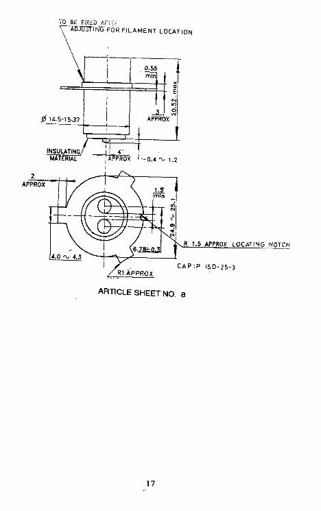
L _.__. _ _. ___.__ ___.------. --
TO BE FiX<D k.i: I; >7fNT;-FOR FILAMENT LOCATION
I 0.55 min
, . I I-: f :: E
x
pr lb.51$3? APp3ROX _.I:
I
INSULATING MATERIAL 0.4 QJ 1.2
CAP :P 15D-25-3
ARTICLE SHEET NO. 8
17

TO BE FIXED AFTER \ADJuS~~NG FOR FILAMENT LO CAT ION.
P 15D-25-1
ARTICLE SHEET NO. 9
18
h

REFERENCE PIN FROM
SW\ OfWING
SECTION a-b
Q 8.5 -
R 1.3 1.7
* Radius r must not exceed dimension U.
Cap P43t-38
ARTICLE SHEET NO. 10
19

w 0
TO BE FIXED AFTER
7
RE
NOTCH TO SHOW UPPER DIRECTION R 2.4 APPROX
SECTION A0
CAP:P300-10 -3
ARTICLE SHEET NO. 11

AMENDMENT NO. 3 JUNE 1996 TO
IS 1606 : 1979 SPECIFICATION FOR AUTOMOBILE LAMPS
( Second Revision )
[ Page 6, clause 3.1, line 1 ( see also Amendment No. 2 ) ] - Substitute ‘six’ for ‘seven’.
[ Page 12, Table 3C, co1 11, all rows ( see also Amendment No. 2 ) ] - Substitute ‘6.3 V’for ‘6.0’, ‘ 13.2V’for ‘12.OV’ and ‘28.OV’for ‘24.0 V ‘.
[ Page 12, Table 3E, co1 12, all rows ( see also page 10 of Amendment No. 2 ) ] - Substitute ‘13.2 Volts’ for ‘12.0 Volts’ and ‘28.0 Volts' for ‘24.0 VOW.
[ Page 12, Table 3E, co1 15, Rows 5 and 6 ( see also page 10 of Amendment NO. 2 ) ] - Substitute ‘1900 lumen’for ‘1000 lumen’ and ‘1000 lumen’for ‘640 lumen’.
[ Page 12, Table 3E, co1 7, Table for dimension ‘e’ on light centre lengtll of RefNo. HE 12/l (see alsoAmendment No. 2 ) ] - Substitute:
‘28.5 + 0.45’ for ‘28.5 t ass - 0.25 - 0.45
[ Page 12, Table 3E, co1 7, Table for dimension ‘e’ on light centre length of RefNo. HE 24/l (see alsoAmendment No. 2 ) ] - Substitute:
‘28 + 0.45’ f or ‘29.0 + 0.60’ - 0.25
( Page 12, fable 3E, co1 13, Row 6 ( see also Amendment No. 2 ) ] - Substitute ‘80’for ‘81’.
[ Page 12, Table 3E, co1 8, dimension ‘f, Rows 1 and 3 ( see also Amendment No. 2 ) ] - Substitute:
‘1.7 + 0.7’for ‘1.7 t 0.5’ and ‘2.0 * 0.7’for ‘2.0 + 0.4’. - 0.6 - 0.3
[ Page 22, clause 6.2 ( see also Amendment No. 2 ) ] - Substitute ‘Inspection test quantity’ for ‘Inspection test quality’.
(Page 22, chrse 6.4, line 3 ) - Substitute ‘20 lamps for ‘10 lamps’.
(ETD23)
Printed at Simco Printing Press. Delhi

/
h N
L
.