is-2825 pressure vessels
DESCRIPTION
is 2825TRANSCRIPT

Irl-
b
E
Y

As in the Original Standard, this Page is Intentionally Left Blank
1s : 2825-1969
INDIAN STANDARD
UNFIRED PRESSURE VESSELS SECTIONAL COMMITTEE, EDC 48
BUREAU OF INDIAN STANDARDS, NEW DELHI
FIRST I’UBI,ISHEI) MARCH 1971
Fifth Reprint MARCH 1992
Sixth Rcpint JANUARY 1994
Seventh Reprint NOVEMBER 1996
Eighth Reprint AUGUST 199s
0 BUREAU OF INDIAN STANDARDS
UDC 66.023: 621.642
Price Rs. 550.00
PRIN’ED IN 1NDIA
Al‘ I(I\Y fC_AY PRINTERS, DELfII, INDIA AND I’UBLISIIED l3Y
BUREAU OF INDIAN STANDARDS, 9 BAIIADUR SIiAH ZAFAR MARG, NEW DELHI 110 002

Unfired Pressure Vessels Sectional Committee, EDC 48 Chairman
SHRI V. MAHAD~VAN
SHRI N . c. BAOCIfI SHRI S.-,G. BANRBJEE SHRI J. BASU
SHRI N. THANDAVAN ( Alternate) SHRI A. K. BHATTACHARYA
SHRI T. BHARDWAJ (Alternate ) SHRI S. R. BHISE Directorate General of Factory Advice Service & i&our
Institutes, Bombay DEPUTY DIRECTOR R~ISEARCH ( MET-I )
AWT DIRECTOR STANDARDS ( LOCO ) ( Alfernate )
Railwav Board ( Ministry of Railways)
SHRI D. S. DESAI M.N. Dastur & Co Pvt Ltd, Calcutta SHRI AMRI~H N. FOZDAR Foadar Products, Ahmedabad SHRI S. GHOSH The Alkali & Chemical Corporation of India Ltd, Calcutta SHRI B. HILL Lloyd’s Register of Shipping, Calcutta
SHRI G. Coon ( Alornati ) SHRI M. N. LOKUR
SHRI B. S. KANO~TKAR ( AI&mats ) SHRI H. K. MOHANTY SARI M. R. NAOARWALLA
Kirloskar Pneumatic Co Ltd, PWM
Hindustan Steel Ltd, Ranchi Burmah Shell Oil Storage & Distributing Co of India Ltd,
Bombay SHRI S. L. ARANHA ( Alknate)
SHRI K. G. K. RAO SHRI S. S. RAO SHRI V. M. RAO
SHRI K. SATYANARAYANA (Alternate) SHRI S. L. ROY
SHRI S. C. JAIN ( Alternatr ) SHRI K. S. SARMA
Tata Engineering & Locomotive Co Ltd, Jamshedpur Larsen & Toubro Ltd, Bombay The K.C.P. Ltd, Madras
The Industrial Gases Ltd, Calcutta
Department of Heavy Engineering ( Ministry of Industry
SHRI S. N. SENOUPTA SHRI N. P. SINOH
SHRI N. S. SESHADRI ( Alhwnate ) SHRI M. M. SuRI
& Supply ), New Delhi John Thompson India ( Pvt ) Ltd, Calcutta Heavy Electricals ( India ) Ltd, Bhopal
Central Mechanical Engineering Research Institute ( CSIR ), Durgapur
Central Boilers Board, New Delhi ACC-Vickers-Babcock Ltd, Calcutta Tata Chemicals Ltd, Mithapur
TECHNICAL ADVISER ( BOILERS ) SHRI 1). G. TURNBULL SHRI M. K. VADOAMA
SHRI S. BALAKRISHNAN ( Al&no&.) SHRI K. S. WHITEHO~SE SRRI I<. A. I. WILLIAMSON SHRI B. S. KRWHNAMACHAR,
Director ( Strut & Met ) 7 SHRI M. V. PATANKAR,
Director ( Mech Engg )
Representing
The Fertilizers and Chemicals Travancore Ltd, Udyogamandal
National Test House, Calcutta Directorate General of Technical Development, New Delhi The A.P.V. Engineering Co Pvt Ltd, Calcutta
Kuljian Corporation (I) Pvt Ltd, Calcutta
Indian Engineering Assoc’ation, Calcutta Binny’s Engineering Wor E; s Ltd, Madras
Director General, IS1 ( Ex-oj7cio Mem6er )
SHRI M. G. KRISHNA RAO
Deputy Director ( Mech Engg ), ISI
Materials Subcommittee, EDC 48 : 1
COWUW
SmI S. C. LAHIRI
Members
SHRI s. L. ARANHA
Hindustan Steel Ltd, Ranchi
Burmah Shell Oil Storage and Distributing Co of* India Ltd, Bombay
L>EPUTY DIRECTOR RESEARCH (MET - I ) SlIRI 1%. HILL
Srrm G. CODD ( Alternate) SHRI N. P. SINoH
SHRI N. S. SESHADRI ( Alternate )
Railway Board ( Ministry of Railways ) Ll<lyd’F R(@ster of Sllipping, Calcutta
Heavy Eleciricals ( India ) Ltd, Bhopal
Design and Fabrication Subcommittee, EDC 48 : 2
SARI J. BASIJ SHRI D. S. DESAI SHRI S. GIIOSH SHRI 13. HILL
SHRI G. CODD ( Akernale )
The A.P.V. Engineering Co Pvt Ltd, Calcutta M.N. Ddstur & Co Pvt Ltd, Calcutta The Alk.\li & Chrmical Corporation of India Ltd, (ialcutta Lloyd’s Register of Sllipping, Calcutta
V

Members
SHRI J. P. MIJKHERJBE DR R. S. DUBEY ( Altemah )
SHRI M. H. PHERWANI SkQI V. M. RaO
SHRI K. SATYANARAYANA ( Alf~n&) REPRILSENTATIVE
S&iRt S. N. SENGUPTA SENIOR INSPECTING ENGINEER SHRI N. P. SIKGII
SHQI N. S. SESHADRI ( Altemale ) TECHNICAL ADVISER ( BOILERS )
Representing
Walchandnagar Industries Ltd, Walchandnagar
Larsen & Toubro Ltd, Bombay The K.C.P. Ltd, Madras
Central Mechanical Engineering Research Institute ( CSIR ), Durgapur
John Thompson ( India ) Pvt Ltd, Calcutta Railway Board ( Ministry of Railways j Heavy Electricals ( India ) Ltd, Bhopal
Central Boilers Board, New Delhi
Testing and Inspection Subcommittee, EDC 48 : 3
Concenrr
SHRI S. R. BHISE Directorate General of Factory Advice Service and Labour Institutes, Bombay
Members
SHRI S. L. ARANHA
SHRI M. R. NAGARWAL ( Alterno& ) SHRI S. Gnose
SHRI C. J. HENT~ ( Altematd ) SHRI B. HILI:
SHRI G. CODD ( Alkma& ) SHRI V. M. RAO
SHRI K. SA~ANARAYANA ( Alternate) SHRI S. N. SENGUPTA SENIOR INSPECTING ENGINXER TECHNICAL ADVISER ( BOILERS )
Burmah Shell Oil Storage and Distributing Co of India Ltd, Bombay
Imperial Chemical Industries ( India ) Pvt Ltd, Calcutta
Lloyd’s Reglstrr of Shipping, Calcutta
The K.C.P. Ltd, Madras
John Thompson ( India) Pvt Ltd, Calcutta Railway Board ( Ministry of Railways ) Central Boilers Board, New Delhi
Code of Practice for Welding Pressure Vessels Subcommittee, SMDC 14 : 4
SHRI S. N. SENGUPTA
Members
SHRI N. C. BAGCHI .% SHRI A. K. Bose
SHRI J. C. KAPUR ( Altnnate ) DEPUTY DIRECTOR RESEARCH (MET-I
SHRI A. JEAVON~
SHRI V. ~~AHADEVAN
SHRI V. R. RAMA PRA&D SHRI H. L. PRABHAKAR ( Al&a& )
SHRI K. G. K. RAO SHRI S. C. ROY
Editing Panel
Conr’ener SHRI V. MAHADEVAN
Mem bns
SHRI S. P. BATRA
SHQI S. C. JAIN (Alternate) SHQI S. C. DEY SHRI J. N. GOSWAMY
SHQI H. S. RAO ( Alternate ) SHRI H. H. JETHANANDANI SIIRI $-I. R. S. RAO &RI S. c. ROY
vi
John Thompson ( India j Pvt Ltd, Calcutta
National Test House, Calcutta ACC-Vickers-Babcock Ltd, Durgapur
Research, Designs & Standards Organization ( Ministry of Railways )
The Indian Sugar & General Engineering Corporation, Yamunanagar
The ~art~~lers & Chemicals Travancore Ltd, Udyoga-
Heavy Electricals ( India ) Ltd, Tiruvcrumbur
Tata Engioecring & Locomotive Co Ltd, Jamshcdpur Central Boilers Board, New Delhi
The Fertilizers and Udyogamandal
Chemicals Travancorc Lto,
Department of Industrial Development ( Ministry of Industrial Development, Internal Trade & Gumpany Affairs )
Chief Inspector of Boilers, Assam Lloyd’s Register of Shipping, Bombay
The Fertilizer Corporation of India Ltd, Sindri Bbrat Hravy Electricals Ltd, Tiruchirapalli ChiePInspcctor of Boilers, WCSI Bengal
CONTENTS
0. FOREWORD
SECTION I GENERAL, MATERIALS AND DESIGN
I
1. GENERAL
2. MATERIALS OF CONSTRUCTION AND ALLOWABLE STRESS VALUES
3. DESIGN 4. FLANGE CALCULATIONS FOR NON-STANDARD FLAWOES 5. PRESSURE RELIEVING DEVICES
SECTION II FABRICATION AND WELDING .6. MANUFACTURE AND WORKMANSHIP 7. WELDING QUALIFICATIONS
. . . 5
. . . 9
9.. 11
. . . 43 . . . 56
. . . .*.
SECTION Ill INSPECTION, TESTS, MARKING AND RECORDS
8. INSPECTION AND TESTS .*.
9. MARJUNO AND RECORDS ‘...
APPENDICES
APPENDIX A ALLOWABLE STREET VALUES FOR FERROUS AND NON-FERROUS MATERIAL . . . APPENDIX B ELEVATED TEMPERATURE VALUES FOR CARBON AND Low ALLOY STEELS
WITH UNCERTIFIED HIOH TEMPERATURE PROPERTIES . . .
APPENDIX C STRESSES FROM LOCAL LOADS ON, AND THERMAL GRADIENTS IN, PRESSURE VESSEts . . .
APPENDIX D TENTATIVE RECOMMENDED PRACTICE FOR VESSELS REQUIRED TO OPERATE AT Low TEMPERATURES . . .
APPENDX E TENTATIVE RECOMMENDED PRACTICE TO AVOID FATIGUE CRACKINO . . . APPENDIX F ALTERNATE METHOD FOR DETERMINING SHELL THICKNESSES OF CYLINDRICAL
AND SPHERICAL VESSELS UNDER EXTERNAL PRESSURE BY USE OF CHARTS . . .
APPENDIX G TYPICAL DESIGN OF WELDED CONNECTIONS . . .
APPENDIX H PRO FORMA FOR THE RECORD OF WELDING PROCEDURE QUALIFICATION/ WELDER PERFORMANCE QLJALIFICATION TEST . . .
APPENDIXJ WELDINO OF CLAD STEEL AND' APPLICATION OF CORROSION-RESISTANT LININGS ..*
APPENDIX K METHOD OF PREPARINQ ETCHED SPECIMEN .*.
APPENDIX L PRO FO~A FOR REPORT OF RADIOORAPHIC EXAMINATION . . .
APPENDIX M PRO FOMA FOR MAKER’S CERTIFICATE OF MANUFACTURE AND PRODUCTION TEST .I.
APPENDIX N INSPECTION, REPAIR AND ALLOWABLE WORKING PRESSURE FOR VESSELS IN SERVICE *..
65 79
95 110
115
124
126
175 178
180 195
224
226 231 232
233
235
vii
IS a 2025 - 1969
0. FOREWORD
0.1 This Indian Standard was adopted by the publications: Indian Standards Institution on 19 March 1969, after the draft finalized by the Unfired Pressure ISO/R 831-1968 Rules for construction of Vessels Sectional Committee had been approved stationary boilers. International Organi- by the Mechanical Engineering Division Council. zation for Standardization.
0.2 Pressure vessels are widely used in chemical and petroleum industries, for generation of steam and for storage and conveyance of compressed and liquefied gases.
0.3 Boilers and similar steam raising equipment and gas cylinders meant for storage and conveyance of compressed and liquefied gases are covered by statutory regulations in this country. Pressure vessels not coming under the purview of these regulations are not covered comprehensively under any other regulations, though the Indian Factories Act, 1948 and the Rules made thereunder touch upon certain aspects. It was felt, therefore, that a code of practice covering unfired pressure vessels should be prepared.
0.4 Safety of pressure vessels is important and, therefore, it is recommended that pressure vessels are obtained from reliable manufacturers and are manufactured under the survey of a compe- tent engineering inspection authority or organiza- tion. The intent of this requirement may be regarded as satisfied when inspection is carried out by a competent personnel of a separate engineering inspection department maintained by the pur- chaser of the vessel. An inspection department maintained by the manufacturer does not satisfy the requirements except in the case of vessels for the manufacturer’s own use and not for resale provided the requirements of statutory regulations are met with,
0.5 Proper inspection of pressure vessels in opera- tion is as important as proper design and manu- facture. For the information of the user of the vessel, details of inspection during service are included in Appendix N.
0.6 All pressures in the code, unless otherwise specified, are gauge pressures.
0.7 In the preparation of this code, considerable assistance has been derived from the following
INSTA 20/Sekr. 37-1957 Recommendation regarding welded pressure vessels. Part I : Rules for construction. Dansk Standardi- seringsraad ( Denmark ).
AD Merkblatt H, SchweiBen von Druckbehal- tern aus Stahl, 1960 ( Welding of steel pres- sure vessels ). Vereinigung der Technishen Uberwachungs-Vereine.
Swedish Pressure vessel code i959. The pressure vessel commission, the Royal Swe- dish Academy of Engineering Sciences, Stockholm.
Swedish Code for welding of pressure vessels ( boiler welding code ). The Royal Swedish Academy Sciences, Stockholm.
of Engineering
B.S. 1500 :- Fusion welded pressure vessels for use in the chemical, petroleum and allied industries.
Part 1 : 1958 Carbon and low alloy steels.
Part 3 : 1965 Aluminium. British Standards Institution.
B.S. 15 15 : Part I : 1965 Fusion welded pressure vessels ( advanced design and construction ) for use in the chemical, petroleum and allied industries. Part I : Carbon and ferritic alloy steels. British Standards Institution.
B.S. 1515 : Part II : 1968 Austenitic steel fusion welded pressure vessels .-( advanced design and construction ) for use in the chemical, pr:roleum and allied industr-ies. British Standards Institution.
ASME Boiler and pressure veshcl code 1963. The American Society of XJechanical Engineers, New York.
Account has also been taken of the work to date done by ISO/TC 11 Boilers and Pressure L’essels.

As in the Original Standard, this Page is Intentionally Left Blank
SECTION I GENERAL, MATERIALS AND DESIGN
1. GENERAL
2. ~~ATERIALS 01. CONSTRL~CIION AXW ALLCWAELE STRESS VALUES
2.1 Ma~elkls
2.2 AlloIv.?llle SlWhS
2.3 Materials for I,oM. ‘l‘empcraturc Service 2.4 h,iatrrials fix. \Velding
3. DESIGN
3.1 Gcllcl-al
3.2 Corrosion, llrwjon ant1 Protection 3.3 i=ylinrlricnl and Spherical Shcils 3.4 Domcci llnds 3.5 Coni,al I<ncls 3.6 Unstiqd E’lnt 1 Icacls and Cwcrs
3.7 Stayed and l%racdPlatcs 3.8 Openings, Branches ad Compensation 3.9 Access and lnspcction Openings 3.10 Bolted Flange Connections 3.11 Ligamer.t Efficiency 3.12 Jacketed Vessels 3.13 sIIpporl’ 3.14 intrrnal Sllnclllrcs
4. FLANGE CAM:UI.ATIOSS foR KON-PTANDAHD FLANGES
4. r General 4.2 Fasteners 4.3 Classification of l+inges 4.4 Flanges Subject to internal Pressure 4.5 Bolt Loads 4.6 Flange Monw~lts 4.7 Flallge S~WSSCS
4.8 Allowable Fl.?ngc Strrsscs 4.9 Flanges Snbiwt lo I;xtcrnal Pressure
5. PRESSURE k3LJEVING nEVlcES
5.1 General 5.2 Design 5.3 Marking 5.4 Capacity of Relief Valves 5.5 Pressure Setting of a Pressure Relieving Device 5.6 Installation of Press~.xc Relieving Devices 5.7 Discharge Lines
. . 5
. . . 5
. . . 5
. . . 6
. . . 9
. . . 9
. . . 10
. . . 11
. . . 11
. . . 11
. . . 11
. . . 12
. . . 12
. . . 17
. . . 21 *.. 24 . . . 28
. . . 30
. . . 35
. . . 36 a.. 36 ..D 39 . . . 41 . . . 41
. . . 43
. . . 43
. . . 43
. . . 43
. . . 43
. . . 45
. . . 53
. . . 56
. . . 56 1.. 56
. . . 56
. . . 56 . . . 61 .*. 61 ..* 61 . . . 62 . . . 62 ..” 62
1. GENERAL
1.1 Scope
1.1.1 This code covers minimum construction requirements for the design, fabrication, inspec- tion, testing and certification of fusion welded unfired pressure vessels in ferrous as well as in non-ferrous metals.
1.1.1.1 This code does not include the following:
4
b)
c)
4
e)
f )
S)
h)
3 k)
Vessels designed for pressure exceeding 200 kgf/cm2;
When the ratio of outside to inside dia ( D,/Q ) of the shell exceeds 1.5;
Hot water supply storage tanks heated by steam or any other indirect means when none of the following limitations is exceeded: 1) a heat input of 50 000 kcal/h,
2) water temperature of 1 lO”C, 3) a nominal water capacity of 500 litres;
Vessels having an internal operating pres- sure not exceeding 1 kgf/cm2 with no limi- tations on size;
Vessels having an internal diameter not exceeding 150 mm with no limitations on pressure;
Steam boilers, steam and feed pipes and their fittings coming under the purview of Indian Boilers Act, 1923, or any revision thereon;
Vessels in whi.ch internal pressure is due solely to the static head of liquid;
Vessels with a nominal water capacity of 500 litres or less for ccntaining water under pressure including those containing air, the compression of which serves only as a cushion;
Vessels for nuclear energy application; and
Vessels, receivers and tanks covered by other Indian Standards.
1.X.1.2 Nothing in this standard is intended to contravene any provision of the Indian Factories AC:. 1948; Indian Boilers Act, 1923; Gas Cylinder Rules, 1940 or any regulations made thereunder.
1.1.2 Fabrication by any fusion welding process is acceptable provided that the requirements of the procedure qualification tests ( ste 7.1 ) are met and are acceptable to the inspecting authority.
1.2 Terminology
1.2.0 For the purpose of this code, the following definitions shall apply.
fs:2825.1!69
1.2.1 Pressure Vessels - All vessels, pipe lines and the like for carrying, storing or receiving steam, gases or liquids at pressures above the atmospheric pressure. The external branches and pipe lines covered by this code shall terminate at the first point of connection by bolting, screwing or welding to the connecting piping.
1.2.2 Maximum Working Pressure - The maxi- mum gauge pressure, at the co-incident metal temperature, that is permitted for the vessel in operation. It is determined by the technical requirements of the process.
1.2.3 Design Pressure - The pressure ( internal or external ) including the static head used in the design calculations of a vessel for purpose of determining the minimum thickness of the various component parts of the vessel.
1.2.3.1 It is obtained by adding a minimum of five percent or as may be agreed between the purchaser and the manufacturer, to the maximum working pressure. In the case of vessels subject to inside vacuum and external pressure on the outside, the maximum difference in pressure between the inside and outside of the vessel shall be taken into account.
1.2.4 Design Temperature - The temperature used in design shall not be less than the mean metal temperature ( through the thickness ) expected under the operating conditions for the parts considered except that for parts subject to direct radiations and/or the products of combustion when it shall not be less than the maximum surface temperature expected under operating conditions. In no case shall the temperature at the surface of the metal exceed the maximum temperature listed in the stress tables for materials nor exceed the temperature limitations specified elsewhere in the code.
1.2.4.1 1lrhen the occurrence of different metal temperatures during operation can be definitely predicted for different zones of a vessel, the design of the different zones may be based on their predicted temperatures. When sudden cyclic changes in temperature are apt to occur in normal operation suit;. the design
only minor pressure fluctuations, sh !i \ be governed by the highest
probable operating metal temperature ( or the lowest, for temperatures !)elow -20°C ) and the corresponding pressure.
1.2.4.2 For vessels where direct internal hc&iig is employed or severe exothermic reactions take place, the design temperature shall be at least 25 deg or more than the maximum tempera- ture expected.
1.2.4.3 In case of lined vessels where the wall temperature is expected to be substantially lower than the temperature of contents of the vessel, the design temperature is a matter for agreement between the purchaser and the manufacturer.
5
.
IS:2825-1969
1.2.5 Minimum Thickness - The thickness ob- tained by calculation according to formulae in the code. This is only a minimum value and requires to be increased to allow for other factors affecting the use of the vessel as noted below.
1.2.5.1 Vessels or parts of vessels subject to corrosion and erosion ( mechanical abrasion ) shall have provision made to cover the total amount of the deterioration anticipated over the desired life of the equipment. The actual allowance is a mat:er for careful consideration and agreement hetwccn the purchaser and the manufacturer ( .ree also 3.2 ) .
1.2.5.2 Provision for additional allowances should be made to take care of additional stresses due to:
4
b)
cl
4
e) f )
impact loads, including rapidly fluctuating pressure; weight of the vessel and contents under operating and test conditions; superimposed loads, such as other vessels, platforms and ladders, piping, insulation, and corrosion or erosion resistant lining; wind loads and earthquake loads where required; thermal stresses; and reactions of supporting lugs, ring, saddles or other types of supports.
1.2.6 Lt’eld Joint Eficienv Factor ( J) - The ratio of an arbitrary strength of the welded joint to the strength of the plates welded expressed as a decimal.
1.2.7 Li.gamrnt E@ciency - The ratio of the strength of a ligament to that of the unpierced plate: expressed as a decimal.
1.2.8 Posi-IZ’eld Heat Treatment - Heat treat- ment of a vessel or portion of it at a predetermined temperature, to relieve the major portion of the residual stresses.
1.2.9 Allowable Stress Value - The maximum stress permissible at the design temperature for any specified material.
1.2.10 Zmpecting Authority - Duly authorized representative of the purchaser or any other compe- tent authority recognized by the statutory regula- tions to inspect the vessel and determine its accepta- bility or otherwise on the basis of this specification.
1.2.11 Fusion Welding* - Fusion welding shall mean any welding process in which the weld is made between metals in a state of fusion without hammering or prcssurc. gas wcldiug;,
It includes arc welding, thermit welding, electron-beam
welding and electro-slag welding.
’ *For other terms relating to welding and cuttinz, see dclinirirrns gilen in IS : 812.1957 ‘ Gloasrry of terms relating to wclcling and cutting of metals ‘.
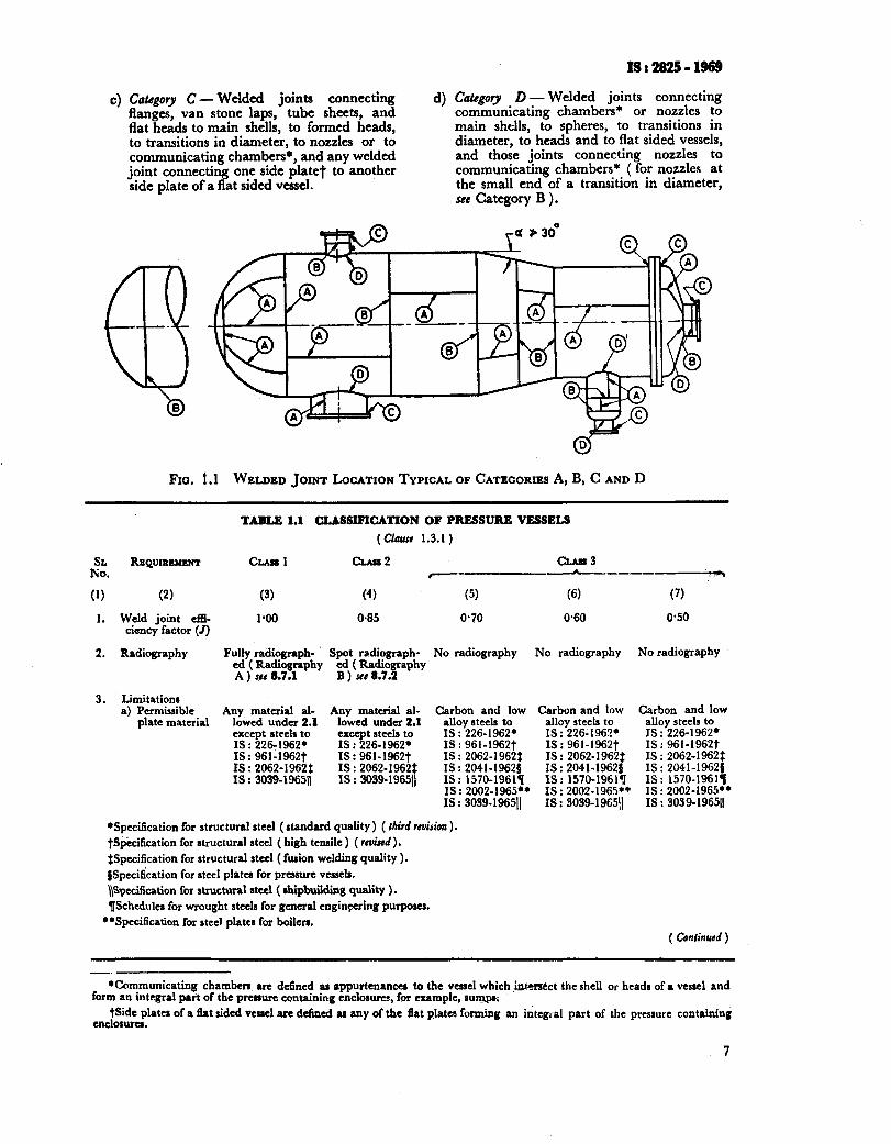
13 Classification
1.3.1 The welded pressure vessels covered by this code shall conform to one of the classes shown in Table 1.1. Each class of construction provides for the use in design, of a joint efficiency factor associated with the material, quality control inspection and tests prescribed for that class.
1.3.1.1 Class 1 z~ssels
a) Vessels that are to contain lethal or toxic substances”,
b) Vessels designed for operation below -2O”C, and
c) Vessels intended for any other operation not stipulated her :n but as agreed to between the purchaser and the manufacturer.
All welded joints of categories A and B of Class 1 vessels shall meet the requirements stipulat- ed in co1 3 of Table 1.1. All butt joints shall be fully radiographed. Circumferential butt joints in nozzles, branches and sumps not exceeding 250 mm inside diameter and 28 mm wall thick- ness need not be radiographed.
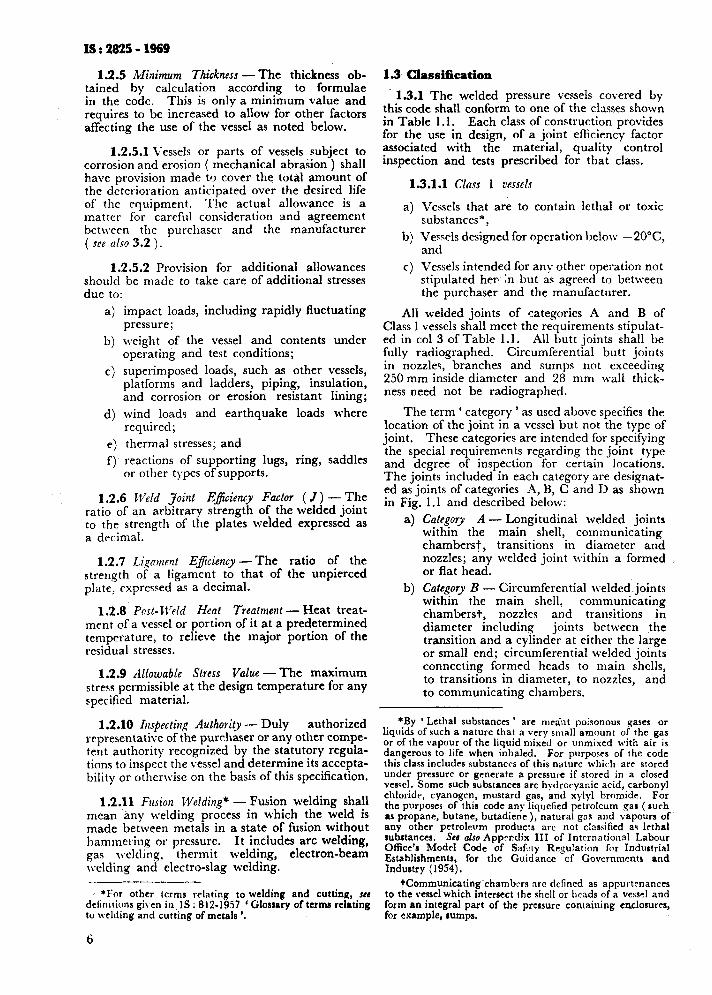
The term ‘ category ’ as used above specifies the location of the joint in a vessel but not the type of joint. These categories are intended for specifying the special requirements regarding the .joint type and degree of insuection for certain locations. The joiits included’in each category are designat- ed as joints of categories A, B, C and D as shown in Fig. 1.1 and described below:
Category A - Longitudinal welded joints within the main shell, communicating chambers?, transitions in diameter and nozzles; any welded joint within a formed or flat head. Category B - Circumferential welded: joints within the main shell, communicating chambers+, nozzles and transitions in diameter including joints between the transition and a cylinder at either the large or small end; circumferential welded joints connecting formed heads to main shells, to transitions in diameter, to nozzles, and to communicating chambers.
4
b)
*By ‘ Lethal substances ’ are meant poisonous gases or liquids of such a nature that a very small amount of the gas or of the vapour of the liquid mixed or unmixed with air is dangerous to life when inhaled. For purposes of the code this class includes substances of this nature which arr stored under pressure or generate a pressure if stored in a closed vessel. Some such substances arc hytlrocyanic acid, carbonyl chloridr, cyanogen, mustard gas, and xylyl bromide. For the purposes of this code any liquefied pctrolcum gas (such as propane, butane, butadiene ), natural gas and vapours of any other petrolrum products arc not classified as lethal subrtances. Ser also Apprcdix III of Intrrnational Labour Oflice’a Modrl Code of Saf-ty Regulation for Industrial Establishments, for the Guidance of Govcrnmcntr and Industry ( 1954).
tCommunicating chambers arc defined as appurtenances to the vessel which intersect the shell or brads of a vc.\sel and form an integral part of the pressure containing enclosures, for example, rumps.
6
.
4 Co&gory C-Welded joints connecting d) flanges, van stone laps, tube sheets, and flat heads to main shells, to formed heads, to transitions in diameter, to nozzles or to communicating chambers*, and any welded joint connecting one side plate? to another side plate of a flat sided vessel.
l8:2825-1969
Category D - Welded joints connecting communicating chambers* or nozzles to main shells, to spheres, to transitions in diameter, to heads and to flat sided vessels, and those joints connecting nozzles to communicating chambers* ( for nozzles at the small end of a transition in diameter, see Category B ).
FIG. 1.1 WELDED JOINT LOCATION TYPICAL OF CATEGORIES A, B, C AND D
ii:.
(1)
1.
2.
3.
TAELE 1.1 CLASSIFICATION OF PRESSURE VESSELS
REQUIRRMENT CLAll 1
(2)
Weld joint efll- cincy factor (J)
(3)
1.00
(4)
0.85 0.70 0.60 0’50
Radiography Fully radiograph- cd ( Radiography
Spot radiograph- ed (Radi
A ) sea 8.7.1 B ) set 8.7. T aphy
Limitations a) Permissible
plate material Any material al-
lowed under 2.1 except steels to IS : 2X-1962’ IS: 961-1962t IS : 2062-1962: IS : 3039-196511
Any material al- lowed under 2.1 except ate& to IS : 226.1962. IS : 961.1962t IS : 2062-1962: IS : 3039-19651)
(51
No radiography No radiography No radiography
Carbon and low alloy steels to IS : 226-1962’ IS : 961-19627 IS : 2062-1962: IS : 2041-19620 IS : 1570-1961q IS : 2002-1965** IS : 3039-196511
Carbon and low Carbon and low alloy steels to IS : 226-1962.
alloy steels to IS : 226-1962.
IS: 961-1962t IS : 961-1962t IS : 2062-1962: IS : 2062-19622 IS : 2041-19620 IS : 2041-19621 IS : 1570-19618 Is : 1570-1961’11 IS : 2002-1965++ IS : 2002-1965+* IS : 3039-196511 IS : 3039-19651
*Specification for structural steel (standard quality) ( third reuision ). tSp&citication for structural steel ( high tensile ) ( rmkd).
$Spccification for structural steel ( fusion welding quality ). ~Spccilkation for steel plates for pressure vessels. \\Specification for structural steel ( shipbuilding quality ). TlSchedulcr for wrought steels for general engineering purposes.
**Specification for steel plates for boilers. ( Continued )
-. *Communicating chambers are defined as appurtmanca to the vessel which i-ct the shell or heads of a ves~cl and
form an integral part of the pressure containing enclosures, for example, surqpl; tSide plates of a tlat sided vessel are defined as any of the flat plates forming an integral part of the pressure containing
enclosura.
7
IS : 2825 - 1969
TABLE 1.1 CLASSIFICATION OF PRESSURE VESSELS - Conki
it.
REQUIREMENT
(1) (2)
b) Shell or end plate thickness
4. Type of joints
5. Quality control
a) Material
b) During fabri- cation
CLASS 1 CLASS 2 CLwr 3
(3)
No limitation on thickness
(4)
Maximum thick- ness 38 mm after adding corrosion allowance
(5) Maximum thick-
ness 16 mm be- fore corrosion al- lowance is added
i) Double weld- ed butt joipts with full pene- tration - eluding bzt joints with metal back- ing strips which remain in place
ii) Single weld- ed butt joints with backing strip J= 0.9 ( see 6.3.6.1)
i) Inspection and tests at steel makers works
ii) Identification and marking of plate and other compo- nents
iii) Inspection of material and plate edges
i) Visual inspcc- tion of surface for objection- able defects
ii) Assembly and alignment of vessel sections prior to weld- ing
iii) Identification and stamping of weld test plates
iv) Inspection iv) Inspection iv) Inspection during wcld- during weld- during weld- ing in pro- ing in pro- ing in pro- grcss, includ- gress, includ- gress, includ- ing second ing second ing second side welding side welding side welding grooves after grooves after grooves aFter preparation preparation preparation by chipping, by chipping, by chipping, gouging, grin- gouging, grin- gouging, grin- ding or ma- ding or ma- ding or ma- chining chining chining
i) Double weld. i) Double weld- ed butt joints, ed butt joints with full pene- with full pene- tration ex- tration ex- eluding butt cluding butt
joints with joints with metal backing metal back- strips which ing strips remain in which remain place in place
ii) Single weid- ii) Sir.gle welded ed butt joints butt joints with backing strip J=O*80
with backing strip 5=0*65
( see 6.3.6.1) (see 6.3.6.1)
i) Inspection and tests at
i) Inspection and tests at
steel makers steel makers work9 works
ii) Identification ii) Identification and marking and marking of plate and of plate and other compo- other compo- nents nents
iii) Inspection of iii) Inspection ot material and material and plate edges plate edges
i) Visual inspec- i) Visual inspec- tion of surface tion of surface for ohjcction- for objection- able defects able defects
ii) Assembly and ii) Assembly and alignment of alignment of vessel sections vessel sections prior to weld- prior to weld- ing ing
iii) Identification iii) Identification and stamping and stamping of weld test of weld test plates plates
(‘5) hfaximum thick-
ness 16 mm be- fore corrosion al- lowance is add- ed
i) Single weld- ed butt joints with backing strip not over 16 mm thick- ness or over
fFie 2; Out-
ii) Single welded butt joints without back- ing strip J- 0.55 6.3.6.1)
( s&s
i) Inspection and tests at steel makers works
ii) Identification and marking of plate and other compo- nents
iii) Inspection of material and plate edges
i) Visual inspec- tion of surface fdr objection- abje defects
ii) Assembly and alignment of vessel sections prior to ield- ing
iii) Inspection during weld- ing gress, ‘%cI):do- ing second side welding grooves after preparation by chipping, gouging, grin- ding or ma- chining
iv) Calibration and dimen- sional check on completion
(7)
Maximum thick- ness 16 mm be- fore corrosion al- lowance is add- ed
i) Single full fillet lap joints for circum- ferential seams only (see 6.3.1)
-
i) Inspection and tests at steel makers works
ii) Inspection of material and plate edges
-
i) Visual inspec- tion ofsurface for objection- able defects
-
-
( Continued )
8
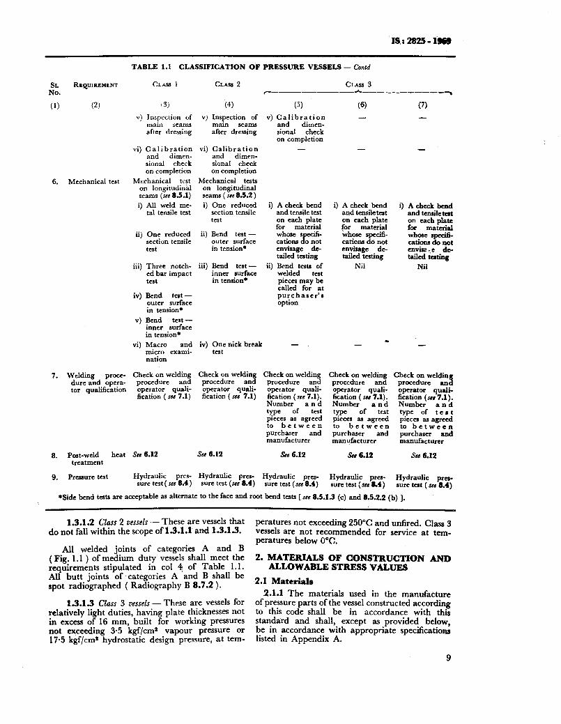
'IS.: 2825-iwb
TABLE 1.1 CLASSIFICATION OF PRESSURE VESSELS - Contd
CLASS I CLASS 2 CLASS 3 ~-_..---- -------*---__--_-_~
(4) v) Inspection of
main seams after dressing
(5)
v) Calibration and dimcn- sional check on completion
(6) -
(7) -
SL RBQUIREM~NT No.
(1) (2)
-
v) Inspection of main seams after dressing
vi) Calibration and dimen- sional check on completion
Mechanical test on longitudinal seams (see 85.1)
i) All weld me- tal tensile teat
vi) Calibration and dimen- sional check on completion
Mechanical tests on longitudinal seams ( see 8.5.2 ) i) One reduced
section tensile test
ii) Bend test - outer surface in tension*
iii) Bend test - inner surface in tension*
-
6. Mechanical test
i) A check bend and tensile test on each plate for material whose s ci6. cations 0 not Je envisage de. tailed testing
ii) Bend tests of welded test pieces may be called for at purchaser’s option
i) A check bend and tensile teat on each plate for material whcac specifi- cations do not envisage de- tailed testing
Nil
i) A check bend and tensile tat on each plate for material whose II
8”“- cations 0 not cnvisz-,e da tailed testing
Nil
ii) One reduced section tensile test
iii) Three notch- ed bar impact test
iv) Bend test - outer surface in tension*
v) Bend test - inner surface in tension+
vi) Macro and micro exami- nation
Check on welding procedure and operator quali- fication ( see 7.1)
iv) One nick break test
n - - -
Check on welding procedure and operator quali- fication (see 7.1)
Check on welding procedure and operator quali- fication (see 7.1). Number and type of test pieces as agreed to between purchaser and manufacturer
See 6.12
7. Welding proce- dure and opera- tor qualification
Check on welding procedure and operator quali- fication ( 5~ 7.1). Number and type of test pieces as agreed to between purchaser and manufacturer
See 6.12
Check on welding procedure and operator qua& 6cic~b;;~,t 7.1).
and type of teat pieces as agreed to between purchaser and manufacturer
Sse 6.12 See 6.12 See 6.12
Hydraulic pres- sure test (see 8.4)
8. Post-weld heat treatment
9. Pressure test Hydraulic pres- sure test (see 8.4)
Hydraulic pres- sure test (see 8.4)
Hydraulic pres- sure test (see a4)
Hydraulic pra- lure teat (~cd 8.4)
aside bend tests are acceptable as alternate to the face and root bend tests [ see 8.5.1.3 (c) and 8.5.2.2 (b) ].
1.3.1.2 Class 2 vessels - These are vessels that do not fall within the scope of 1.3.1.1 and 1.3.1.3.
peratures not exceeding 250°C and unfired. Class 3 vessels are not recommended for service at tem- peratures below 0°C.
2. MATERIALS OF CONSTRUCTION AND ALLOWABLE STRESS VALUES
2.1 Materials
2.1.1 The materials used in the manufacture of pressure parts of the vessel constructed according to this code shall be in accordance with this standard and shall, except as provided below, be in accordance with appropriate specifications listed in Appendix A.
9
All welded joints of categories A and B ( Fig. 1.1 ) of medium duty vessels shall meet the requirements stipulated in co1 4, of Table 1.1. All butt joints of categories A and B shall be spot radiographed ( Radiography B 8.7.2 ).
1.3.1.3 Class 3 vessels - These are vessels for relatively light duties, having plate thicknesses not in excess of 16 mm, built for working pressures not exceeding 3-5 kgf/cms vapour pressure or 17-5 kgf/cm* hydrostatic design pressure, at tem-
IS: 2825-1969
2.1.2 Nothing in the foregoing shall preclude the use of otherwise suitable materia! M-here so agreed by the purchaser, the manufacturer and the inspecting authority. It is recon mended that, in such .cases, pal tir:llar attention be given to the weldability and ductility of the material proposed to IX uacd.
No such material shall have an elongation on L..
a gauge length of 5~65dx, less than 100 -R,
2.2
where So is the ori@% area of cross section and R, is the actual tensile streygth in kgf/mm’ at room temperature subject to a minimum of 16 percent for carbon and carbon manganese steels, 14 percent for alloy steels other than austenitic steels and 25 percent for nusteni!tc steels, for test pieces obtained, prepared and tcstcd in accordance with appropriate Ipdinn Standards.
2.1.3 Materials used frz supporting lugs, skirts, baffles and simi!ar ‘non-pressure parts, we!dcd to vessels shall_ be cf weldable, quality and suitable in other respects for the intended service.
2.1.4 All material shall be suppiied according to IS: 1387-1967” and all threaded fasteners according to IS : 1367-1967t.
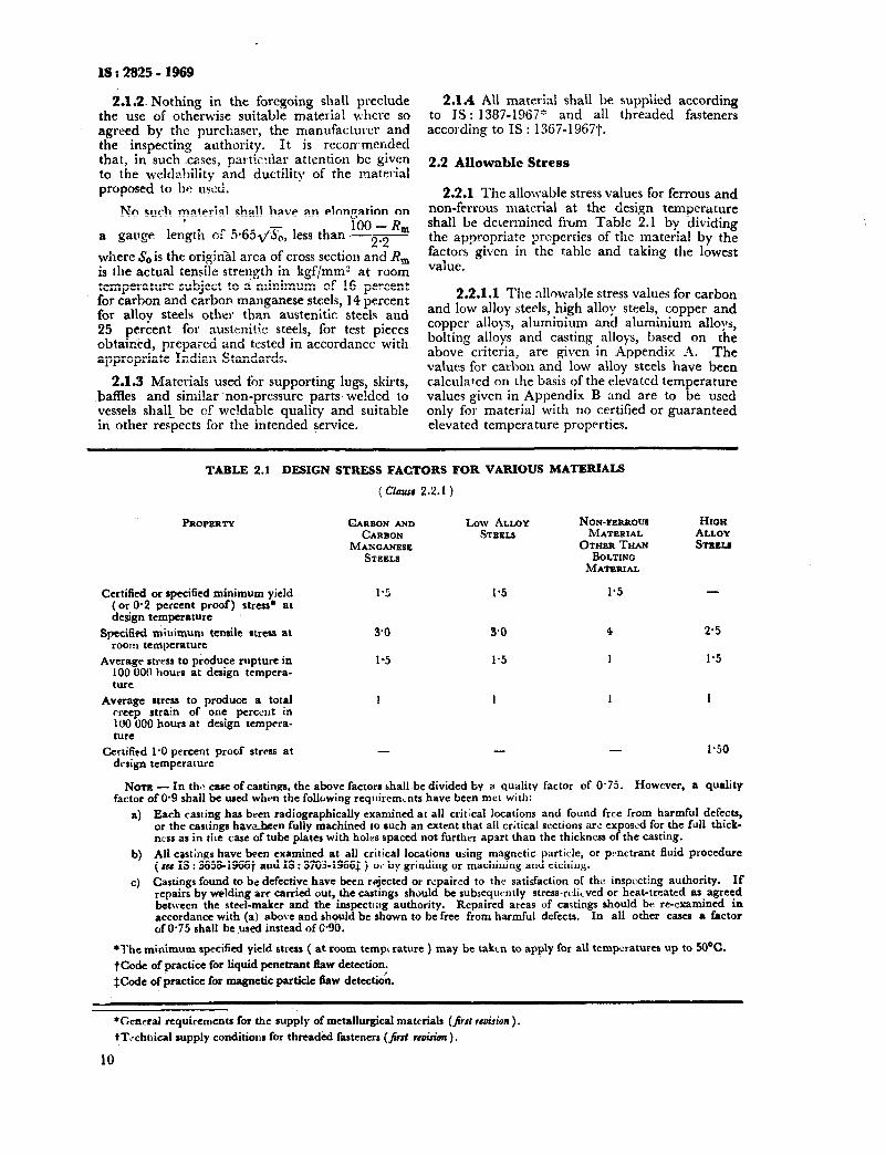
2.2 Allowable Stress
2.2.1 The allowable stress values for ferrous and non-ferrous material at the design temperature shall be delermined from Table 2.1 by dividing the appropriate properties of the material by the factors given in the table and taking the lowest value.
2.2.1.1 The nllowable stress values for carbon and low alloy steels, high alloy steels, copper and copper alloys, aluminium and aluminium alloys, bolting alloys and casting alloys, based on the above criteria, are given in Appendix A. The values for carbon and low alloy steels have been calculated on the basis of the elevated temperature values given in Appendix B and are to be used only for material with no certified or guaranteed elevated temperature properties.
Certified or specified minimum yield (or 0.2 percent proof) stress* at design temperature
Specified miuimum tensile rtrcss at room teniperature
Average stress to produce rnpture in 100 000 hours at design tempera- ture
Average stress to produce a total creep strain of one pcrccut in IO0 000 hours at design tempcra- ture
1.5 l-5
3.0
1.5
4 2.5
1 1.5
1 1 1
Certiflpd 1’0 percent proof stress at design temperature
- - - 1.50
1
TABLE 2.1 DESIGN STRESS FACTORS FOR VARIOUS MATERIALS
( Claurr 2.2.1 )
PROPERTY CARBON AND Low ALLOY CARBON STEEL,9
MANGANESE STEELS
NON-FERROUII HIon MATERIAL ALLOY
OTHERTHAN STI~EU BOLTINQ MATERIAL
N~TB - In the case of casting, the above factors bhall bc divided by a quality factor of 0.75. However, a quality factor of O-9 shall be used when the following rcqtliremLnts have been met with:
a) Each casting has been radiographically examined at all critical locations and found free from harmful defecta, or the castings h&v&cm fully machined IO such an extent that all critical sections arc exposed for the full thick- ncss as in the case of tube plates with holes spaced not further apart than the thickness of the casting.
b) All castings have been examined at all critical locations using magnetic- particle, or p-netrant fluid procedure (see IS : 36581966t and IS : 3703-19663 ) 0,. by grinding or machining and etching.
c) Castings found to be defective have been rcrjected or repaired to thr satisfaction of the inspecting authority. If repairs by welding are carried out, the castings should be subscqucntly stress-rclicved or heat-treated as agreed between the steel-maker and the inspecting authority. Repaired areas of castings should be re-examined in accordance with (a! above and shqvld be shown to be free from harmful defects. In all other cases a frctor of O-75 shall bcused instead of C.90.
*The minimum specified yield stress ( at room tempt raturc ) may be taken to apply for all temperatures up to 50°C.
tCodc of practice for liquid pcnctrant flaw detection.
$Codc of practice for magnetic particle llaw dctcctioh.
*Ccncral rcquircmcnts for the supply of metallurgical materials (&$I rcui.rion ).
tTtchnica1 supply conditiolis for threaded fasteners (jirsl r&ion ).
10
Iy : 2825 - 1969
2.2.2 Where safe stress values for material in compression are required, for example, in the case of the design of vessels subject to loadings ( see 1.2.5.2 and 3.3.2.4) that product longitudinal compressive stresses, it shah bc calculated as given in Appendix C.
2.2.3 Sh~nr Stresses .- The maximum permissible shear stress ( where present alone ) shall not exceed 50 percent of the allowable stress value.
2.2.4 Beming Stressrs - The maximum permissi- ble bearing stress shall not exceed 50 percent of the allowable stress value.
2.3 Materials for Low Temperature Service- Special consideration shall be given to the choice of materials for vessels designed for operation below 0°C. Aluminium and its alloys not being subject to brittle fracture are particularly suitable for operation at temperatures below 0°C. Aus- tenitic stainless steels ( wrought ) are quite suitable fot use up to -200°C. For use below this tempe- rature or where cast materials are used special con- sideration shall be given to the choice of material and design. A recommended practice for carbon and low alloy steel vessels required to operate at low temperatures is given in Appendix D.
2.4 Materials for Welding - The electrodes, filler rods and flux shall satisfy the requirements of appropriate Indian Standards and shall corres- pond to those used in the procedure qualification tests and welder’s performance tests. The follow- ing Indian Standards are available or under pre- paration:
IS : 814-1970
IS : 12781967
IS : 1395-1964
IS : 2680-I 964
IS : 3613-1966
IS : 4972-1969
IS : 5206”I?69
IS :
Specification for covered elec- trodes for metal arc welding of struclural steel ( third revision )
Specification for filler rods and wires for gas welding (Jirst revision )
Specification for molybdenum and chromium molybdenum low alloy steel electrodes for metal arc welding ( revised)
Specification for filler rods and wires for inert gas tungsten arc welding
Specification for acceptance tests for wire flux combinations for submerged arc welding
Specification for resistance spot welding electrodes
Specification for corrosion resisting chromium and chro- mium nickel steel covered electrodes for metal arc welding
Specification for filler wires for metal inert gas lvelding ( under ,4refarutim )
IS : Specification for filler rods and wires for inert gas lvelding ( under preparation )
3. DESIGN
3.1 General - Vessels covered by this code shall be designed for the most severe combinations of operating conditions which may be experienced in the normal operations.
Special consideration shall be given to vessels designed to operate at temperatures below 0°C. A tentative recommended practice for vessels required to operate at low temperatures is given in Appendix D.
Where vessels are subject to alternate heating and cooling, provision shall he made in the design to permit expansion or contraction to avoid exces- sive thermal stresses ( see Appendix E ).
This code does not contain rules to cover all details of design and construction. Where com- plete details are not given, it is the intention that the manufacturer, subject to the approval of the purchaser and/or the inspecting authority, shall follow such details ofdesign and construction lvhich will be as safe as those provided by this code.
3.1.1 Design ‘i’Xckness - In the clauses that follow, methods are given for calculating the thicknesses required for the various parts of a pressure vessel.
3.1.2 Weld Joint Esciency Factors ( J) - The weld joint efficiency factors to be used in the design calculations shall be those specified in Table 1.1.
3.1.3 Loadings
3.1.3.1 In the design of a vessel the following loadings shall be included where relevant:
4 b)
c)
Design pressure including static head;
The weight of vessel and normal contents, or weight of the vessel and maximum con- tent of water specified for the pressure test; and
Wind loading in combination with other loadings.
3.1.3.2 Special consideration may be required given to the effect of the following: to be
a) Local stresses due to supporting lugs, ring girders, saddles, internal structures or con- necting piping;
b)
c)
Shock loads due to water hammer or surg- ing of vessel contents;
Bending moments caused by eccentricity of the centre of working pressure relative to the neutral axis of the vessel;
11
LS : 2825 - 1969
d) Forces due to temperature differences, including the effects of differential expan- sion;
e) Forces caused by the method of supporting the vessel during transit or erection; and
f) Fluctuating pressure and temperature ( see Appendix E ) .
Formal analysis of the effect’ of the above influences is only required in cases where it is not possible to dembnstrate the adequacy of the proposed design, for example, by comparison with the behaviour of comparable vessels.
3.2 Corrosion, Erosion and Protection
3.2.1 General
3.2.1.1 Whenever the word corrosion is used in this code it shall be taken to mean corrosion, oxidation, scaling, abrasion, erosion and all other forms of wastage. Stress corrosion cracking may occur under certain conditions of temperature and environment and cannot be catered for by increas- ing thickilesses. Under conditions, where stress corrosion may occur, consideration shall be given to the materials used and the residual stress in fabricated vessels.
It is impossible to laydown definite precaution- ary rules to safeguard against the effects of corro- sion owing to the complex nature of corrosion itself, which
a)
b)
c)
d)
rniy exist in many forms, for example:
Chemical attack, where the metal is dis- solved by the reagents, it may be general over the whole surface, or localized ( caus- ing pitting ), or a combination of the two;
Rusting, caused by the combined action of moisture and air;
Erosion, where a reagent, otherwise in- nocuous, flows over the surface at a velocity greater than some critical value; and
High temperature oxidation ( scaling ).
Designers should give careful consideration to the effect which corrosion may have upon the use- ful life of the vessel. When in doubt, corrosion tests should be undertaken; these should be carried out on the actual metal ( including welds ) or combination of metals under exposure to the actual chemicals used in service. It is very dangerous to assume that the major constituent of a mixture of chemicals is the active agent as, in many cases, small traces of impurities exert an accelerating or inhibiting effect out of all proportion to the amount of impurity present. Fluid temperatures and velocities should be equivalent to those met with in operation. Corrosion tests should be con- tinued for a sufficiently long period to determine the trend of any change in the rate of corrosion with respect to time; the result may be considered as given below. Corrosion may occur on both sides of the wall of the vessel, particularly with vessels heated by hot gases of combustion:
a) Corrosion rate predictable - Vessels in which corrosion rates may be definitely
12
b)
established by reason of accurate knowledge of the chemical characteristics of whatever substances they are to contain.
Corrosion rate unpredictable - Vessels in which corrosion rates are either variable throughout the vessel or indeterminate \ in magnitude.
Corrosion rate negligible - Vessels in which corrosion rates are known to be negligible.
3.2.2 Additional Thickness to Allow for Corrosion- The allowances adopted shall be adequate to cover the total amount of corrosion expected on either or both surfaces of the vessel.
In cases where corrosion may occur, additional metal thickness over and above that required for the design conditions should be provided, at least equal to the expected corrosion loss during the desired life of the vessel. It is recommended that in all such cases a minimum corrosion allow- ance of 1.5 mm should be provided unless a pro- tective lining is employed.
Where the corrosion effects are negligible, no excess thickness need be provided.
3.2.3 Linings - Vessels may be fully or partially lined with corrosion-resistant material. Such linings may be loose, intermittently attached to the vessel base material or integrally bonded to the vessel base material ( for example, as clad steel). This code does not cover vitreous enamel linings.
Provided linings are designed so as to exclude contact between the corrosive agent and the vessel base material, no corrosion allowance need. be provided against internal wastage of the base material.
Corrosion-resistant linings shall not be included in the computation of the required wall thickness, except in the case of clad steels as may be agreed to between the purchaser and the manufacturer.
The design of linings should take into account the effects of differential thermal expansion.
3.2.4 Wear Plates - Where severe conditions of erosion and abrasion arise. local protective or ‘ wear plates ’ of an easily renewable type should be fitted directly in the path of the impinging material.
3.3 Cylindrical and Spherical Shells
3.3.1 General
3.3.1.1 The thickness shall be not less than that calculated by the following formulae and shall be increased, if necessary, to meet the requirements of 3.1 and 3.2.
3.3.2 Shells Subject to internal Pressure
3.3.2.1 Notation - The following notations are used in the design of spherical and cylindrica’ vessels subject to internal pressure:
t = minimum thickness of shell plates exclusive of corrosion allowance in mm,
P = design pressure in kgf/cms, Dt = inside diameter of the shell in mm, D, = outside diameter of the shell in mm,
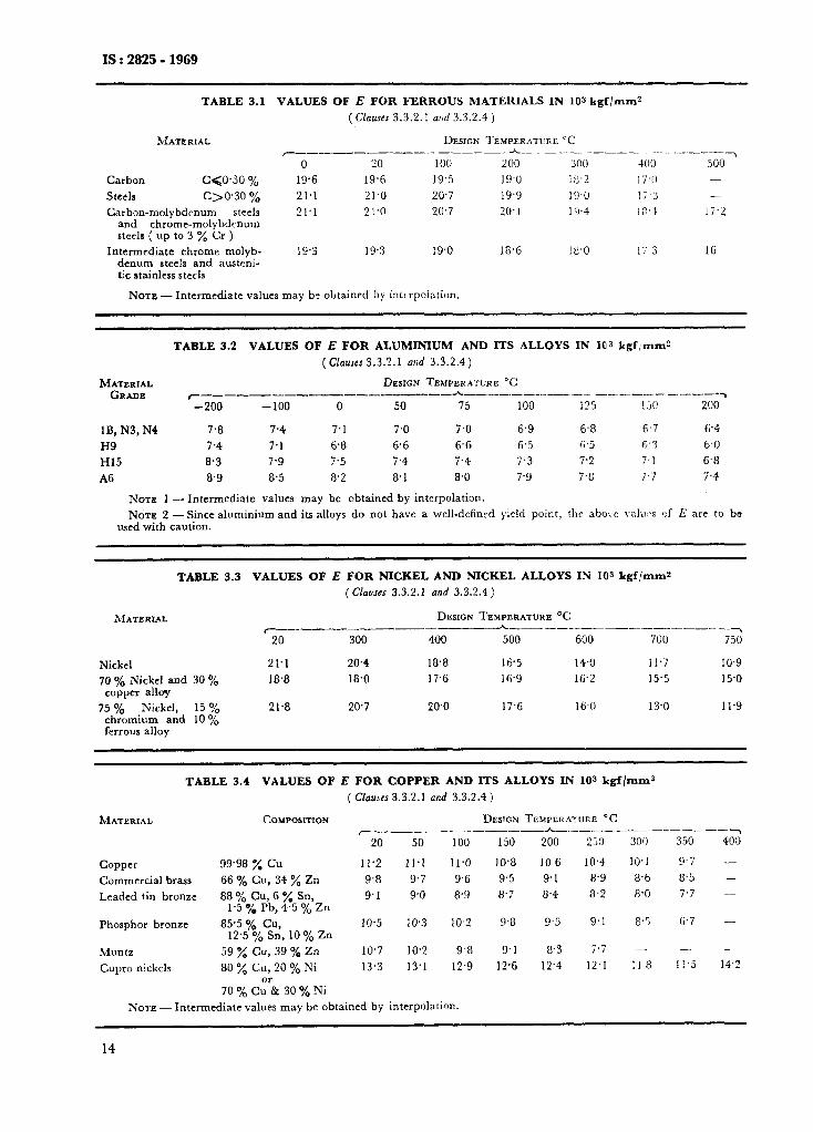
f = allowable stress value in kgf/mm* ( see Appendix A ),
J = joint factor ( see Table 1.1 ), and E = modulus of elasticity of the material at
the operating temperature in kgf/mm* ( see Tables 3.1, 3.2, 3.3 and 3.4 ).
3.3.2.2 Cylindrical shells - The following for- mulae shall apply in the case of cylindrical shells:
PDi PDO t = POOfJ--p = 2OOfJ+p
. . .
or PoOfJt
‘- Dl+t 200fJt --=- Do-t
. . .
.(3.1)
(3.2)
3.3.2.3 Spherical shells - The following for- mulae shall apply in the case of spherical shells:
t = _Pg!_ = PDO 4OOfJ-p 4OOfJ+P
. . .
or P 400fJt 400fJt = -._-.--_=__ Di+t Do-t
. . .
(3.3)
(3.4)
3.3.2.4 Cylindrical vessels under combined laad- ings - Under no circumstances shall the ‘shell thickness ( before adding corrosion allowance ) be less than that given in equation ( 3.1 ).
Where the shell is subjected to loadings addi- tional to those due to internal pressure, the basis of design shall be that the stress equivalent to the membrane stresses shall nowhere exceed the allowable stress.
The equations given below apply to the case where the cylinder is subjected to loads producing a direct longitudinal stress ( for example, from its own weight in the case of a vertical vessel ), a longitudinal bending moment ( for example, from wind or piping loads or, in the case of a horrzontai vessel, the weight of the vessel and contents ) and a torque about the longitudinal axis ( for example, from offset piping and wind loads ).
The following notation is adopted:
J
= allowable stress in kgf/mms; B = allowable stress at ambient temperature
in kgf/mms; # = internal pressure ( design or test as ap-
propriate ) in kgf/cm*; t = shell thickness ( before adding corro-
sion allowance ) in mm; t a = actual shell thickness at time of teat
(including corrosion allowance) in mm; internal, external diameters of shell
young modulus at design temperature and at ambient temperature respec- tively in kgf/mms ( see Tables 3.1, 3.2, 3.3 and 3.4 );
M = longitudinal bending moment in kgf.mm;
T = torque about vessel axis in kgfmm; W = weight ( vertical vessel only ) in kg :
4
b)
for points above plane of support - weight of vessel, fittings, attaeh- ments and fluid supported above the point considered, the sum to be given a negative sign in equation ( 3.5 ); for points below plane of support - weight of vessel, fittings and attach- ments below the point considered, plus weight of fluid contents, the sum to be given a positive sign in equation ( 3.5 );
Ue = equivalent stress ( shear strain energy basis ) in kgf/mms;
Qz = longitudinal stress in kgf/mm*;
oe = hoop stress in kgf/mms; and
t = shearing stress in kgf/mms.
Then
4GPD? + W&4$- uz =
xt (Di+t) . ..(3.5)
ug = PC a-+-t 1 2001
. . . (3.6)
2T T=XtDl(D,+t)
. . . (3.7)
The stress equivalent to the membrane stress on the shear strain energy criterion is given by the Huber-Hencky equation:
CQ. = [
aso - ag bz + uz2 $ 3ra I
4 . ..(3.8)
The requirements are that at design conditions:
ee Gf . ..(3.9a) uz ( tensile ) <f . ..(3.9b)
uz ( compressive ) < 0.125 E ( >
k . . . (3.9c) 0
and at test conditions ( see 8.4 )
ee G 1.3fa uz ( tensile ) < 1 *3fa
. ..(3.9d) . ..(3.9e)
. ..(3*9f)
In all cases each of the signs before the term 4M/Di in equation ( 3.5 ) should be considered.
Values of u,,, ue and t should be determined for each combination of loading during operation and test.
The equations cannot be reduced to a conve- nient explicit expression for the calculation of t and solution by trial and error is necessary.
13
IS : 2825 - 1969
TABLE 3.1 VALUES OF E FOR FERROUS MATERIALS IN 103 kgf/mm2
(Clauses 3.3.2.1 ar:d 3.3.2.4)
MATERNAL DESIGN TEMPERATCRE ‘C r__----__---___ oh_____-_._-__ ~-_.-_-._---~
0 20 100 200 300 ‘lo0 500 Carbon c<o,so o/o 19.6 19.6 19.5 19.0 18.1 17.0 stec1s c>o.30 % 21.1 21.0 20.7 19.9 19.0 17.3 -
Carbon-molybdenum steels 21.1 21.0 20.7 20.1 19.4 1 :I. 1 17.1 and chrome-molybdenum steels ( up to 3 y0 Cr )
Intermediate chrome molyb- 19.3 19.3 19.0 18.6 !8,0 17 3 16 denum steels and austeni- tic stainless htecls
NOTE - Intermediate values may be obtained by interpolation.
TABLE 3.2 VALUES OF E FOR ALUMINIUM AND ITS ALLOYS IN 103 kgfimm?
(Ckmes 3.3.?.1 aad 3.3.2.4)
MATERIAL DESIGN TEMPERATURE “C GRADE r--- __-~-~------_--h____---.__ -_ _______- _ ----my
-200 -100 0 50 15 100 125 150 200
lB, N3, N4 7.8 7.4 7.1 7.0 7.0 6.9 6.8 6.7 6.4 H9 7.4 7.1 6.8 6.6 6.6 6.5 ii.5 6.3 6.0 H15 8.3 7.9 7.5 7.4 7.4 7.3 7.2 7.1 6.8 A6 8.9 8.5 8.2 8.1 8.0 7.9 7.8 7.7 7.4
NOTE 1 - Intermediate values may be obtained by interpolation. NATE 2 - Since aluminium and its alloys do not have a well-defined yield point, the abo\e \-alucs of E are to be
used with caution.
TABLE 3.3
MATERIAL
Nickel 70 0% Nickel and 30 %
copper alloy
75 % Nickel, 15% chromium and 10 % ferrous alloy
VALUES OF E FOR NICKEL AND NICKEL ALLOYS IN 103 kgf/mmz
( &uses 3.3.2.1 and 3.3.2.4 )
DESIGN TEMPERATURE ‘C ~~_____~_~~__~_~~_~~~_~~~_~_~~_~~~_~_~
20 300 490 500 600 700 750
21.1 20.4 18.8 16.5 14.0 11.7 IO.9 18.8 18.0 17.6 16’9 16.2 15.5 15.0
21.8 20.7 20.0 17.6 16.0 13.0 11.9
TABLE 3.4 VALUES OF E FOR COPPER AND ITS ALLOYS IN 10s kgf/mma
( Clamrs 3.3.2.1 and 3.3.2.4)
MATERIAL COMPOSITION DEDGN TEMPLRAT:IRE ‘C ~-_---_---~~-~ h___--_-- __.. _________~
20 50 100 150 200 250 300 350 400
Copper 99.98 % Cu 11.2 11.1 11.0 10.8 10 6 10.4 10.1 9.7 - Commercial brass 66 % Cu, 34 % Zn 9.8 9.7 9.6 9.5 9.1 8.9 8.6 8.5 - Leaded tin bronze 88 “/b Cu, 6 % Sn, 9.1 9.0 8,9 8.7 8.4 8.2 8.0 7.7 -
1.5 % Pb, 4.5 % Zn Phosphor bronze 85.5 % Cu, 10.5 10.3 10.2 9.8 9.5 9.1 8.5 6.7 -
12.5 % Sn, 10 % Zn Muntz 59 % cu, 39 % Zn 10.7 10.2 9.8 9.1 8.3 7.7 - - -
Cupro nickels 80 % Cu, 20 % Ni 13.3 13’1 12.9 12.6 12.4 12.1 118 11.5 14.2
70 % C:& 30 % Ni NOTE - Intermediate values may be obtained by interpolation.
14
IS : 2825 - 1969
3.3.3 Shells Subjected to External Pressure - The thickness of thin-walled shells subjected to external pressure may be calculated either by the formulae given below or by the method given in Appendix F.
3.3.3.1 Notation - The following notation has been used in the formulae in this section:
t = minimum thickness of the shell material in mm,
D ,, = outer diameter of the shell in mm, and
L = effectiv length in mm.
In the case of cylindrical shells, it is the maxi- mum of the following values and is measured parallel to the axis of the shell:
4
b)
4 ,
In
The distance between head bend lines plus one-third the depth of each head, when no stiffening rings are present; the maximum centre distance between two adjacent stiffening rings; and the distance from the centre of the nearest stiffening to the head bend line plus one- third the depth of the head.
the case of spherical shells, the effective length is equal to the inside radius of the spherical shell:
p = design pressure in kgf/cm”;
o = O-2 percent proof stress in kgf/mms; and
X = the ratio of the elastic modulus E of the material at the design metal tempe- rature to the room temperature elastic modulus ( see Tables 3.1, 3.2, 3.3 and 3.4 for values of E at different temperatures ).
3.3.3.2 Thickness of cylindrical shells under external pressure - The thickness of the cylindrical shells under external pressure is given by equations 3.10, 3.11, or 3.12 as is applicable:
L 0.58 lop it ( > 38 loot #
a) for C -PF=-.
( ) Do or < -.-- L-0
t DO
=-iz- I: L!$L+ 0.053 E$ 4 ( )I . ..(3.10)
loot or+=-&F r-
C 0.053 K& g
( )I DO . ..(3.10a)
0
b) for L 14.4
Do7.-or> 1E. or
W) 6 iGO?-’ ___ Do
t = 1.03 x go x (pK)i but not less than
3*5pDo _
200a . . . (3.11)
0.91 orp = -
K but not greater than
200to
m . . . (3.11a)
c) In all other cases
t = -f& c
0.075p. $- . K ]’ . . . (3.12) 0
13.3 1OOt 8
or p = ( ) D, . . .
LX.-
(3.12a)
--.A
DO
3.3.3.3 Thickness of spherical shells under external pressure -The thickness of spherical shells under external pressure is given by equation 3.13:
t5PD0 800
. . . (3.13)
80ut orp=D . (3,13a)
0
3.3.3.4 StzjTem?zg rings
a> General -Stiffening rings are generally used with cylindrical shells subjected to external pressure. They exte&ld around the circum- ference of the shell and may be Iocated on the inside or the outside of the shell.
16
P L6
d
K
b)
The following notation has been used in the formulae given:
= moment of inertia in cm4 of the ring section around an axis extending through the centre of gravity and parallel to the axis of the shell. For a stiffening ring, welded to the shell all around, a part of the shell, equal to 4t may be included in the moment of inertia when calculating the stiffening ring;
= design pressure in kgf/cm*;
= length between the centres of two adja- cent stiffening rings in mm;
= diameter through the centre of gravity of the section of an externally 1ocaJed stiffening ring or the inner diameter of the shell in the case of an internally located stiffening ring in mm; and
= the ratio of the elastic modultis of the material at the design metal temperature to the room temperature elastic modulus (see Tables 3.1, 3.2, 3.3 a_nd 3.4 for values of E at different temperatures ).
The moment of inertia of the stiffening ring Ze shall not be less than that calculated by the formula.
1, = 7 x lo-‘PLBd3K .:. (3.14)
15
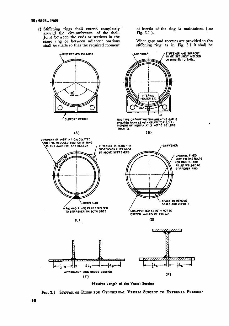
IS:2825- 1969
c) Stiffening rings shall extend completely of inertia of the ring is maintained ( SCI around the circumference of the shell. Fig. 3.1 ). _ , Joint between the ends or sections in the same ring or between adjacent portions shall be made so that the required moment
When gaps and recesses are provided in the stiffening ring as in Fig. 3.1 it shall be
+JNStlFFENED CYLINDER
L SUPPORT CRADLE
(A)
NER AND SUPPORT SECURELY WELDED
ETED TO SHELL
I Lx THIS TYPE OF CONSTRUCTIONWHEN THE GAP IS GREATER THAN lEN07H OF ARC TO FIOS.2. MQMENT OF INERTIA Al x NOTTO BE LESS THAN IS
(B)
MOMENT OF INERTIA I CALCULATED THIS REDUCED SECTION IF RING
IS CUT AWAY FOR ANY REASON /-IF VESSEL IS HUNG THE +TlFFENER SUSPENSION LUGS MUST GE ABOVE STIFFENERS
CHANNEL FIXED WlfH FITTING BOLTS (OR RIVETS) AND FILLET WELDED TO STIFFENER RING
/
-l_ DRAIN SLOT
/
L SPACE TO REMOVE SCALE AND DEPOSIT
PACKING PLATE FILLET WELDED TO STIFFENER ON BOTH SIDES UNSUPPORTED LENGTH NOT 10
EXCEED VALUES OF FIG. 02
ALTERNATIVE RING CROSS SECTION
(El (Fl
Effrctlvr Length of the Vessel Section
Fro. 3.1 STIPPENINO RINQS FOR CYLINDRICAL VESSELS SUBJECT TO EXTERNAL PRIWIRI
16
4
suitably reinforced so that the required moment of inertia is maintained.
However, if the gap in the stiffening ring does not exceed the value calculated from Fig. 3.2, reinforcement for the stiffener ring need not be provided. Reinforcement for the stiffener ring also need not be provided if in case of gaps in adjacent stiffening rings, the length of the unsupported shell arc does not exceed 60” and the gaps in adjacent rings are
, staggered 180”.
Stiffening rings may be attached to the shell by welding or brazing or by any other method of attachment suitable for the material of construction. Brazing may be used when the vessel ‘is not to be stress- relieved later.
The welding may be continuous or intermit- tent. In the case of intermittent welds:
1) the welds on either side of the ring shall overlap at least by 10 mm for stiffening rings situated on the outisde, and
2) the welds on either side of the ring shall be at least equal to one-third the circumference of the vessel in length, for stiffening rings situated on the inside.
lS:2825=1S!J
e) Rings for supporting trays, plates, etc, in fractionating columns or similar construe- tions may be used as stiffening rings provided they are adequate for the duty.
3.3.3.5 Thickness of tubes, and P;pes wh used as tubes under ex&rnalpressure - This shall be deter- mined from the chart on page 18.
The thickness as determined from the graph shall be increased when necessary to meet the following requirements :
4
b)
Additional wall thickness should be pro- vided when corrosion, erosion or wear due to cleaning operations is expected. Where tube ends are threaded_, additional wall thickness is to be provrded in the amount of 0.8 p ( where p is the pitch in mm ).
NOTE -The requirements for rolling, expanding, or other&e eating tuba in tube plates may require additional wall thickncu and careful choice of materiala because of possible relaxation due to ditkrential expansion atreuer.
3.4 Domed Ends
3.4.1 General -Domed ends of hemispherical, semi-ellipsoidal or dished shape shall be designed in accordance with the requirements of3.49 and 3.4.6. The calculated thickness shall be increasec& if necessary, to meet the requirements of 3.1 and 3.2.
I
/
J
,I /
I/’ i I ,I I YI / I/I I IA!J VIlll/ I/ I A I II/II A’
/I
30
25 A I IIII I IIII 0.10 045 0*2 Oa3 @& 0*50*6 0*8 l*O 1.5 2 3 4 5 6789x) 15 20 25
LENGTH BETWEEN HEADS OR STIFFENING RINGS f OUTSIDE DIAMETER +f
FIO. 3.2
17
IS : 2825 - 19fi9
600
“E $100
.z . 60
z 2 60
g 50
a. 40
5 $ 30
0
20
2 3 4 5 10 20 ALLOWABLE STRESS, kgf/mm2
CHART FOR DETERMINING WALL THICKNESS OF TUBES UNDER EXTERNAL PRESSURE
3.4.2 Limitations of Shabe - Ends shall conform to one of the following shapes ( see IS : 4049-1968* ):
a) Hemispherical (-see Fig. 3.3A ), b) Semi-ellipsoidal ( see Fig. 3.3B ).
The ratio of major axis to minor axis should not be greater than 2.6 : 1.
*Specification for formed ends for tanks and pressure vessels.
Y I I
I I
c\ Dished and flanged ( see Fig. 3.3C ): ’
1)
2)
The inside radius of dishing Rt shall be not greater than the outside diameter Do, and
The inside corner radius rr shall pre- ferably be not less than 10 percent of the inside diameter and in no case less than 6 percent nor less than 3t.
18
(A) tfcmispherical Ends
I Do ----A
FIG. 3.4
(B) Semi-Ellipsoidal Ends
(C) Dished and Flanged Ends
FIG. 3.3 DOMED ENDS
3.4.3 Openings in Ena!s
3.4.3.1 Holes cut in domed ends shall be circular, elliptical or obround. Openings having a diameter exceeding O-5 DO shall be subject to special consideration. The radius of flanging I of flanged-in openings ( see Fig. 3.4 ) shall be not less than 25 mm.
NOTE - An obround opening is one which is formed by two parallel sides and semi-circular ends.
3.4.3.2 Uncompensated openings - Flanged-in and other openings shall be arranged so that the distance from the edge of the end is not less than that shown in Fig. 3.5. In all cases the projected width of the ligament between any two adjacent openings shall be at least equal to the diameter of the smaller opening as shown in Fig. 3.6.
3.4.3.3 Compensated 0pCnings - Openings, where compensation is provided otherwise than by general thickening of the end ( over and above that required for an unpierced end ), shall comply with the requirements of 3.8. Ends containing only openings. compensated in accordance with 3.8 shall be regarded as plain ends for the purposes of applying Fig. 3.7.
j-------------A FIQ. 3.5
WHICH EVER IS SMALLER
FIO. 3.6
Fro. 3.4-3.6 TYPICAL UNICBINFORCED OPENINGS
3.4.4 Xotation -The following notation has been employed:
t = minimum calcdated thickness of the end in mm;
P = design pressure in kgf/cm*;
&Do= inner and outer diameters of the end in mm;
hE = effective outside height of the end in mm;
where hE = h,, or
whichever is the least --
hi, k. = inside and outside height of the end in mm;
r1, ro = inside and outside knuckle ( corner ) radius in mm;
19
ls : 28!&.- 1969
&,Ko = inner and outer crown radius in mm;
f = allowable stress value in kgf/mms;
flange;
d = diameter of the largest uncomnensat-
20
J = weld joint factor for any welded seam ed opening in the head. In the case
in the end including circumferential of an elliptical opening the major
end-to-shell seam in the case o,f ends axis of the ellipse in mm;
having no straight flange; c = a shape factor obtained from Fig. 3.7;
= I.0 for ends made from one plate and attached to shell with a straight
and
= length.of the straight flange.
2.5
O-01 045 0*20 0*25
hE
Do
Fro. 3.7 SHAPR FACTOR FOR DOMXD ENDS
5-o
3.0
1.0
x3,2925-1%9
p =-design pressure in kgf/cms;
f = allowable ,stress in kgf/mm* determined in accordance with 2.2;
J = weld joint factor;
Dk = inside diameter of conical section or end at the position under consideration ( see Fig. 3.8 ) in mm;
DI E: outside di?meter of conical section or end ( see Fig. 3.8 ) in mm;
I1 = inside radius of transition knuckle which shall be taken as 0.01 & in the case of conical sections without knuckle transi- tion in mm;
a,a+s = angles of slope of conical section ( at the point under consideration ) to the vessel axis ( see Fig. 3.8 ) ;
Y = difference between angle of slope of two adjoining conical sections ( see Fig. 3.8 ) ;
c = a factor taking into account the stress in the knuckle ( see Table 3.6 ); and
L = distance, from knuckle or junction within which meridional stresses determine the required thickness ( see Fig. 3.8 ) in mm.
3.4.5 Thickness of Ends Concave to Pressure - The thickness of the ends shall be determined by the- equation:
. (3.15)
200fJt Or!)-- DC . . . . . .
0
(3.16)
NOTE - The external height of dishing h,, may be determined from e uation 3.17 in the case of ends of partially spherical 9 orm:
6
ho=%- d(R. - q) X (R.++--2 rj ._ (3.17)
NOTE 1 _In the case of ends containing no uncompen- ;;t;~Dopcnmgs,. read C from full curves 1/&=@002
0 I 0.04 mtcrpolatmg as necessary.
NOTE 2 - In the case of ends containing uncompcn- sated openin@, read C from broken lines curves
dd/t.l)o- 5.0 to dd/t.L&=O.fi interpolating as neces- sary. In no case shall C be taken as smaller than the value for similar unpierced end.
3.4.6 Thickness of En& Convex to Pressure
3.4.6.1 @he&ally dished ena3 - The thickness of the ends dished to partially spherical form shall be greater of the following thicknesses:
a) The thickness of an equivalent sphere, having a radius R. equal to the outside crown radius of the end, determined in accordance with 333.3.
b) The thickness of the end under an internal pressure equal to 1.2 times the external pressure.
3.4.6.2 Ellipsoidal en& -*The thickness of ends of a true semi-ellipsoidal shape shall be greater of the following thicknesses:
a) The thickness of an equivalent sphere, having a radius & calculated from the
% values of - in Table 3.5, determined in
Do accordance with 3.3.3.3.
b) The thickness of the end under an internal pressure equal to 1.2 times the external pressure.
3.4.7 Constructiotuzl Details - Typical permitted connections between ends and shells are shown in Table’6.2.
3.5 Conical Ends
3.5.1 General - Conical ends and conical reducing sections ( set Fig. 3.8 and Fig. 3.9 ) shall be designed in accordance with the following formulae. The calculated thickness shall be increased, if necessary, to meet the requirements ~43.1 and 3.2.
Conical ends may be constructed of several ring sections of decreasing thickness as determined by the corresponding decreasing diameter.
35.2 .Notation -The following notations have been used in the formulae:
t 3 minimum calculated thicknas of co&al section or end in mm;
3.5.3 Conical En& Subject to Internal Pressure - The stresses in the knuckle or in the circumferential seam at the wide end of the cone acting in a meridional direction are predominantly bending stresses and the stresses acting in a circumferential direction are predominantly membrane stresses. Both these factors are taken into account in turn in equations 3.18 and 3.19. The greater of the two wall thicknesses calculated is chosen. For shallow cones, the thickness may be determined by the method given in (c) of this clause below, even though the resulting wall thickness may be less than those determined by the equations 3.18 and 3.19:
Thickness of knuckle or conical section in junction-The thickness of cylinder and conical section within distance L from the junction shall be determined by:
t=,PD,C, 200fJ
. . .
This thickness of the knuckle or junction shall however be not less than those given by equations 3.19 and 3.20.
If the distance of a circumferential seam from the knuckle or junction is not less than L then J shall be taken as 1.0, other- wise J shall be the weld joint factor appro- priate to the circumferential seam.
l%ickness of conical section away fiem jutution - The thickness of those parts of. conical sections not less than a distance L away
21
IS:!2855-1969
TABLE 3.5 VALUES OF + AS A FUNCTION
( Claue 3.04.6.2 )
OF 2 0
la F0 - PI67 o-178 0.192 0.208 0.227 o.25 o-278 o.313 0.357 0.417 o.50
& li;, = 1.36 1.27 l-182 1.08 0.99 O-90 0.81 o.73 0.65 0.57 0.50
NOTE - The inkrmediate values may be obtained by interpolation.
(A) Cone/Cylinder with Knuckle (6) Conc,/Cylinder without Knuckle
(C) Cone/Cone with Knuckle (D) Cone/Cone without Knucklr
FIG. 3.8 TYPICAL C~SNE SHELL CONNECTIONS
from the junction with a cylinder or other conical section shall be determined by:
provisions of 3.5.1 to 3.5.3 are applicable, except that the thickness shall be not less than as prescrib- ed below:
4
1 t = 20&T~_p x - ..*
Cosa (3a*g) a)
Shallow conical sections - The thickness of conical sections having an angle of inclina- tion to the vessel axis of more than 70” shall be determined by:
tea-5(De--1) xGo $.., (3.20)
The lower of the values given by equations ‘3.19 and 3.20 shall be taken.
3.5.4 Conical Ends Subject to External Pressure - For a conical end or conical section ( frustum ) under external pressure, whether the end is of seamless or butt welded construction, the general
b)
The thickness of a coni’cal end or conical section under external pressure, when the angle of inclination .of the conical section ( at the point under consideration ) to the vessel axis is not more than 70”, shah be made equal to the required thickness of cylindrical shell, in which the diameter is D&osa and the effective length is equal to the slant height of the cone or conical section, or slant height between the effective stiffening rings, whichever is less.
The thickness of conical ends having an angle of inclination to the vessel axis of more than 70” shall be determined as for a flat cover ( see 3.6 ).
TABLE 3.6 VALUE6 OF C AS FUNCTION OF * AND rl/Da
( chUS6 3.5.2 )
rip
\ 0 --
10.
20’
3o”
450
6!Y
75.
O-01 0.02 O-03 0.04 0.06 O-08 O-10 0’15 0.20 O-30 O-40 O-50
o-70 0.65 0.60 0.60 o-55 o-55 o-55 O-55 O-55 0.55 O-55 O-55
1.00 0.90 O-85 0.80 0.70 O-65 0.60 O-55 O-55 0’55 0’55 O-55
195 I.2 1-l 1-O 0.90 0.85 O-80 0.70 o-55 0.55 0’55 O-55
2.05 l-85 l-65 l-5 l-3 l-2 1-l o-95 0.90 o-70 0’55 0.5:
3-2 2.85 2.55 2.35 2.0 1’75 I.6 1.4 l-25 1’00 0.70 0.55
6.8 5-85 5.35 4-75 3.85 3.5 3.15 2.7 2.4 1’55 la0 o-55
(A) Cone Section
n -I
I
Di I-- l
(6) Cone Section with Trrnsition Knuckles
(C) Reversed Curvr Se&on
Fxo. 3.9 ALTERNATIVE FORMS OF OPENINGS IN DOMED ENDS FOR CASES WHEN d EXCEEDS D/2
23
ss12825-1969
3.5.5 Constructional Details - Connections bet- ween cylindrical shells and conical sections and ends shall preferably he by means of a knuckle transition radius. Typical permitted details are shown in Fig. 3.8. Alternatively conical sections and ends may be butt welded to cylinders without a knuckle radius when the change in angle of slope P between the two sections under consi- deration does not exceed 30”.
3.6 Unstayed Flat Heads and Covers
3.6.1 General - Flat covers and end plates shall be designed in accordance with the following formulae and the thickness shall be increased, if necessary, to meet the requirements of 3.1 and 3.2.
3.6.1.1 flotation - The following notation has been used in the following formulae:
a = short span of non-circular heads in mm;
b = long span of non-circular heads or covers measured perpendicular to short span in mm;
c = a factor depending upon the method of attachment to shell ( see Table 3.7 );
D = diameter or short span measured as in Table 3.7;
ho = gasket moment arm equal to the radial distance from the centre line of the bolts to the line of gasket reaction in mm;
L = perimeter of non-circular bolted heads measured along the centres of the bolt holes in mm;
1 = length of the flange of flanged heads in mm;
:
= design pressure in kgf/cms; = allowable stress value in kgf/mms;
t = minimum thickness of flat head or cover, exclusive of corrosion allowance in mm;
tr, te = required and actual thickness of the shell under design conditions, exclusive of corrosion allowance in mm;
FB = total bolt load in kgf; and
Z = a factor for non-circular heads depend- ing upon the ratio of short span to long span a/b (*see Fig. 3.10 ).
3.6.2 Thickness of Flat Headr and Covers
3.6.2.1 The thickness of flat unstayed circular heads and covers shall be calculated by the follow- ing formula :
. . . (3.21)
When the head or cover is attached by bolts causing an edge moment, the thickness t shall be calculated for both initial tightening and design conditions and the greater of the two values selected.
24
l-60
1*60
N
2 1.60
w u &A &y 1*30
00
1'20
1.10 0 O-2 04 0-6 1
RATIO f
Fro. 3.10 VALUE OF COEFFICIENT 2 FOR NON-CIRCULAR FLAT HEADS
3.6.2.2 The thickness of non-circular heads and covers shall be calculated by the following formula :
f _ CZt2 P 10 2/ 7
. .
When the head or cover is attached by .bolts causing an edge moment, the thickness t shall be calculated for both initial tightening and design conditions and the greater of the two values selected.
3.6.3 Spherically Dished Covers and Quick Opening Closures
3.6.3.1 Spherically dished covers - The thick- ness of spherically dished ends secured to the shell through a flange connection by means of bolts shall be calculated by:
3@h t=BOqfJ
. . . (3.23)
provided that the inside crown radius R of the dished cover does not exceed 1.3 times the shell inside diameter Di and the value of 100 t/R is not greater than 10.
3.6.3.2 Quick opening closures -- These shall be so designed that failure of anyone holding ele- ment cannot result in release or failure of all of the other holding elements. Closures of this type shall be so arranged that it may be determined at all times by usual examination that the holding devices are in good mechanical condition and that their locking elements when closed are in full engagement.
They shall be so designed that when the vessel is installed:
a) the closure and its holding elements are fully engaged in their intended operating position before pressure can be built up in the vessel, and
IS : 2825 - 1969
TABLE 3.7 VALUES OF D AND C FOR TYPICAL UNSTAYED FLAT HEADS
( Cl~trsez 3.6.1 and 3.6.2 )
_ _ --.__... __
SL DESCRIPTION No.
1. Forged heads
TYPICAL EXAMPLE REMARKS
--___
--rib-- r-o-25 t HIN
(a)
ri,.,l,MIN
(b)
c-o*5
c10.5
2, Flanged flat heads butt ‘welded to the vessel
b-- CENTRE OF WELO
TANGENT LINE
r-31 MIN
C = 0.35 when C = 0.45 when C = 0.5 when
r>2t
D= Di-rand
taper is 1 : 4
D = Di and
132; 0.25f(r<21
D = D, - I and
taper is 1 : 4
3. Heads lap welded or brazed to the shell
I--CENTRI OF LAP
TANGENT LINL
r 231 MIN
2
C= 0.45 when I> I.1 - 0.8 %) d/or and
C = 0.55 in other care:
( Continued )
25
IS : 2825 - 1969
TABLE 3.7 VALUES OF D AND c FOR TYPICAL UNSTAYED FLAT HEADS - Con!d
SL
No. DESCRIPTION TYPICAL EXA~LE REM.AHEI
4. Plates welded to the inside of the. VCSSCI
--It I-- (b)
-- c= 0.7 if Lut not less than Wri5
5. Plates welded to the end of the rhell
c = Q-7
6.
C = 0.7 4 T but nut less than 0.55
Plates welded to the end of the shell with an additional fillet weld on the inside
( Cohwd )
26
IS t 2825 - 1969
TABLE 3.7 VALUES OF D AND c FOR TYPICAL UNSTAYED FLAT HEADS - Contd ~_~_. _. ______.. _.-.-.._-- .- .-. ..~--- --..----- _~.. _.~ .~_ _______
SL J)ESCRIPTIOS ‘T\.PiC.\l. EX.1&IPLr, 12OMARKS
X0.
8. Covers with a n a r r o \Y face b o I t e d ilange joint
--- t +-- -_it i--’
(a) (b) where 4 is the bolt load
9. Autoclave man- hole covers D ,> 610 mm
_-
10. Plates inserted into the end of
hacld vessel aud
in place by a positive me. chanical locking arrangement
All means of’ failures shall be resisted with a factor of safety of at least 4. Seal welds may be used if desired.
---It!-- (a)
THREADED RING 7
c = 0.55
( Contbwd )
27
IS : 2825 - 1!369
TABLE 3.7 VALUES OF D AND C FOR TYPICAL UNSTAYED FLAT HEADS - Contd
REMARKS
11. Plates ;nsrrted into the vessel as shown and rhe end of the vessel crimped over
D >GO ~,ni
_- .._ ________..___~ _. .______ _____. ___~~ Crimping shall be done cold only when the operation
will not injure the metal. In other cases crimping shall be done when the entire circumfcrencc of the cylinder is uniformly heated to the proper forging
4SV MAX temperature for the material. Crimping angle shall )OPYIN not he less than 30’ but need not exceed 45”.
c = 0.7 MIN tl= t OR ts
WHICH EVER .IS
(a) AS* MAX 30°HIN 1 /SEAL WELD,
Di& or 4ZO.05
and p>ZOf
@I
b) pressure tending to force the closure clear of the vessel will be released before the closure can be fully opened for access.
In case the requirements (a) and (b) are not satisfied in the design of the closure, provision shall be made so that devices to accomplish this can be added when the vessel is installed.
Vessels with quick-opening _closures shall be installed with a pressure gauge or warning device and, in addition, with means which will prevent pressure being applied unless the cover and holding elements are in proper operating condition and prevent disengagement of the holding elements while there is pressure loading on the cover.
3.7.2.3 When the stays are of such long span that there is a possibility of undue sagging, consi- deration should be given to the support of the stays.
3.7.2.4 Stays shall not bear against the shell of the vessel except through the medium of a substantially continuous ring.
3.7.3 Thickne.rs of the Stqzd and Braced Plates
3.7.3.1 The thickness of the stayed and braced plates shall be calculated by the following formula :
3.7 Stayed and Braced Plates where 3.7.1 General-Plates which are braced by
being connected to each other by means of stays, tubes, blocks, etc, shall be designed in accordance with the following formulae. Though the method of calculation used is primarily applicable to flat parallel plates., it may, when suitable, be applied to slightly inclmed plates or surfaces which because of their smaller thickness than required under the clauses of this code are to be stayed as flat plates.
3.1.2 Design
3.7.2.1 Stays may be attached to the plate stayed by screwing, welding, expanding, bolting or by a combination of any of these methods.
3.7.2.2 Stays made up of more than one bar welded into the body, that is composite bars, shall not be used.
28
(3.24)
t = minimum thickness of the plate in mm;
p = design pressure in kgf/cm*; D = diameter of the largest circle in
mm which may be inscribed bet- ween the supporting points of the plate ( see Fig. 3.11 ) ;
f 5 allowable stress value in kgf/mmz; and
C = a factor depending on the mode of support and is given by Fig. 3.12A to 3.12F. When the plate is supported in different ways on the circumference of the inscribed circle of diameter D, a mean value is to be adopted for C.
Fra. 3.:! STAYS FLAT PLATE
(A) FLANGE OF A FLANGE0 HEAD (8) WELDED BRACE
c= 0*45 c = o-45
/
yy .p .4
___-_a-___--__--
-_--_-- ___---_-_ -
(C) WELDED TUBE STAY (0) EXPANDED AND BEADED TUBULAR STAY
c= 0*55 c= o-55
(E) FIAd STAV WITH WASHER OF ( F) BAR STAY W!TH WASHER AND DIA NOT LESS THAN Z-5 TIMES REINFORCING PLATE OF DIP. THE STAY DIA NOT LESS THAN O-30
c- 0*45 c= 0.40
EIG. 3.12 VALUES OF CO-EFFICIENT C: DEYESDIWG ON THP. 'I'ypp, OF STAY 29
IS : 2825 - 1969
3.8 Openings, Branches and Compensation
3.8.1 General
3.8.1.1 Openings in the shell or end plates of a vessel shall be circular, elliptical or obround with a ratio of major to minor inside diameter not exceeding 2.
3.8.1.2 It is preferable to locate all openings clear of welded seams.
3.8.2 Limitation of Formulae
3.8.2.1 The formulae and rules given here for the design of compensation around openings are intended to apply directly to openings and branch connections not exceeding:
4
b)
one-third the inside diameter of the shell for cylindrical and spherical shells; one-third the inside diameter of the conical section measured where the nozzle axis pierces the inner surface of the conical sec- tion, and for conical sections; and one-half the outside diameter of the end for ends.
Compensation of larger openings should be the subject of special consideration and, if neces- sary, the adequacy of the proposed design should be demonstrated by means of model tests or hydraulic proof test in accordance with 8.4.
In the case cf large openings in ends, the use of a conical or reversed curve reduction piece ( see Fig. 3.9 ) is recommended.
Details shown in Fig. 3.13k ti 3.13E offer progressive reductions in stress concentration. This consideration is of particular significance in the case of services involving severe fluctuations in pressure or temperature ( see Appendix E ) or low temperature duties ( see Appendix D ).
3.8.2.2 The formulae and rules given here are not directly applicable to:
a) oblique nozzles when the angle between the axis of the nozzle and a line normal to the shell surface exceeds 15’, and
b) multiple openings or rnultiple branches where the axial distance is less than 1.5 times average diameter.
3.8.3 Uncompensated Openings - Isolated open- ings in cylindrical or conical shells or spheres having a diameter not exceeding that given by Fig. 3.14 subject IU a maximum of 200 mm, do not require added compensation. For the limitations governing uncompensated openings in the ends, see 3.4.3.
Openings spaced apart a distance not less than:
4 ta It, 1 L = ( t,/t, - 0.95 ) ***
but in no case less than twice the diameter of the larger opening may be regarded as isolated openings.
30
where L = distance between centres of any
two, adjacent openings in mm; d = diameter of largest opening, in the
case of an elliptical or obround opening the mean value of the two axes in mm;
t, = actual thickness of vessel before corrosiou allowance is added in
mm; t, = required thickness of vessel putting
J = 1 *O before corrosion allowance is added in mm; and
PDO X = a factor equal to -- ( see 18%
Fig. 3.14A & B.)
When X has a value of unity or greater, the maximum size of an unreinforced opening shall be 50 mm.
3.8.4 Location of Compensated Openings in Ends - Compensated openings in domed ends of semi- ellipsoidal or dished shape should preferably be so lo&ted that the outside of any attachment or the edge of any additional compensation will not be a greater distance from the centre of the end than 40 percent of the outside diameter of the end. In cases where this is not practicable the vessels shall be subjected to a hydraulic proof test ( see 8.4 ) except where similar vessels have proved the adequacy of the design by satisfactory operation under comparable conditions over a substantial period ( see 3.4.3.2 for uncompensated openings ).
3.8.5 Compensated Openings in Shells and ends
3.8.5.1 Genwl - At all planes through the axis of the opening normal to the vessel surface the cross-sectional area requirements for compensa- tion as calculated below shall be satisfied:
Material in added compensation, or in a branch, should have similar mechanical and physical properties to that in the vessel shell or end. Where material having a lower allowable stress than that of the vessel shell or end is taken as compensation its effective area shall be assumed to be reduced in the ratio of the allowable design stresses at the design tempera- ture. No credit shall be taken for the additronal strength of material having a higher stress value than that in the shell or end of the vessel.
3.8.5.2 Calculation of compensation required
a) Area required to be compensated-The total cross-sectional area of compensation, A, required in any given plane for a vessel under internal pressure shall be not less than:
A=d.t, . . . .a. (3.26) where
d= nominal internal diameter of the branch plus twice the corrosion allowance in mm ( sde Fig. 3.15 and 3.16 ),
IS : 2825 - 1969
t, =
(Cl (D)
FIG. 3.13 TYPICAL COMPENSATED OPENINGS
thickness, in mm, of an unpierced shell or end calculated from equa- tions 3.1 and 3.3 and if the opening is located clear of any welded seam J= 1.0 except that:
1) For dished and JIanged and hemi- spherical en& - When the open- ing and its compensation are located entirely within the spherical portion of a dished end, tr js the thickness required for a sphere having a radius equal to the spherical portion of the end.
2) For semi-ellipSoida ends - When the opening and its compensa- tion are in an ellipsoidal end and are located entirely within a circle having a radius, measured from the centre of the end, of 040 of the shell diameter, tr is the thickness required for a sphere having a radius R, deriv- ed from the following:
where
b)
(E)
hi = depth of dishing of end plate measured internally ( see Fig. 3.3 ) in mm,
D, =
RI =
inside diameter of end plate in mm, and inside radius of equivalent sphere in mm. 3) When the opening is in a cone,
t is the thickness required for a cone of diameter DK where the centre line of the opening pierces the inside surface of the cone.
Material available for compensation - Only material located within the rectangle wxyt ( see Fig. 3.15 ) shall be deemed effec- tive compensation.
1)
2)
3)
The portion of the shell or end available for compensation shall be taken as:
A S=d(t-tr-c) . . . (3.27)
The portion of the branch external to the vessel available for compensation shall be taken as:
A, = 2H, ( t - t, - c) (3.28)
The portion of the branch inside the vessel available for compensation shall be taken as:
Ai=2Zf,(t-2C) ..* (3.29)
31
where
A, = area c-4 portion of shell or end whit-11 is clB~ti\-e as wmpensa- tion mm2;
A,, = area of portion of branch pipe
external to vessel which is effec- tive as compensation in mm2;
t = actual thickness of part, that is, shell! end or branch, under consideration, in mm;
30 -
i
*Oo 50000 lOO@xJ fnm2
DRUM DIAMETER x THICKNESS (Dxt)
FIG. 3.14A MAXIMUM DIAMETER OF NON-REINFORCED OPENINGS
32
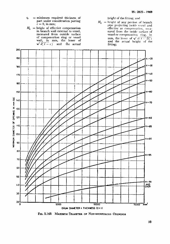
tr = minimum required thickness of part under consideration putting c = 0, in mm;
Zfr = height of effective compensation in branch wall external to vessel, measured from outside surface of compensation ring or vessel wall, in mm, the lesser of s/ d( t - c) and the actual
Hz ==
IS : 2825 - 1969
height of the fitting; and
height of any portion of ljranch pipe prqjecting insiclc \:csel and effective as cornpmsdtii)il, mm- sured from the inside surf&e of vessel or compensation rii1.g. in mm, the lcsscr of ~~;i'(m'ie~~Ili:, and the actual height of the fitting;
I90 .
D&i DlAMETERx THICKNESS (DXt)
Fm.3.14B MAXIMUM DIAMETER OF NON-REINFORCED OPENINGS
K=*20
K=*30
K--.&O
K**99 AN0 OVER
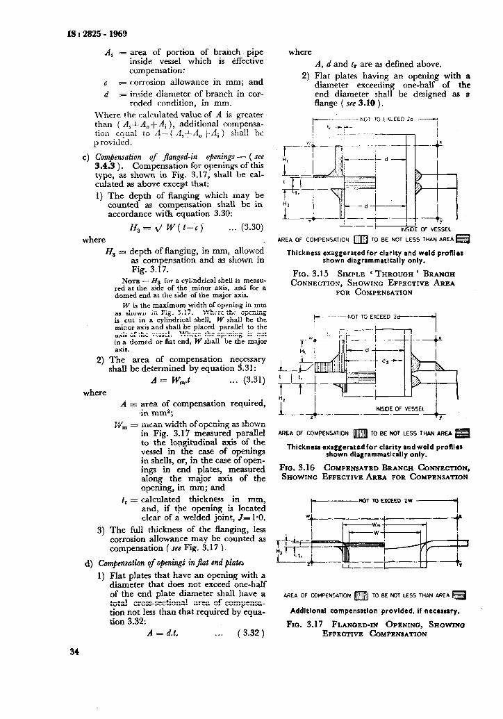
IS : 2825,- 1969
4
Ai = area of portion of brahch pipe inside vessel which is effective compensation:
c F corrosion allowance in mm; and
d = inside diameter of branch in cor- roded condition, in mm.
Where the calculated value of A is greater than ( A,+ A,+ Ai ), additional compensa- tion equal to I- ( A,+A, tAi ) shall be p rovided.
Compensation of jlanged-in openings - ( see 3.4.3 ) . Compensation for openings of this type, as shown in Fig. 3.17, shall be cal- culated as above except that:
1) The depth of flanging which may be counted as compensation shall be in accordance with equation 3.30:
Hs = 2/ W( t-c) . . . (3.30)
where
H, = depth of flanging, in mm, allowed as compensation and as shown in Fig. 3.17.
NOTE -- Ha for a cylindrical shell is measu- red at the side of the minor axis, and for a domed end at the side of the major axis.
W is the maximum width of opening in mm as shown in Fig. 3.17. Whrre the opening is cut in a cylindrical shell, W shall be the minor axis and shall be placed parallel to the axis of !he vessel. Where the opening is cut in a domed or flat end, W shall be the major axis.
2) The area of compensation ne ssary shall be determined by equation zr .31:
A = &,.t . . . (3.31)
where A = area of compensation required,
in mms;
W, = mean width of opening as shown in Fig. 3.17 measured parallel to the longitudinal axis of the vessel in the case of openings in shells, or, in the case of open- ings in end plates, measured along the major axis of the opening, in mm; and
t, = calculated thickness in mm, and, if the opening is located clear of a welded joint, ,I= 1-O.
3) The full thickness of the flanging, less corrosion allowance may be counted as compensation ( see Fig. 3.17 1.
d) Compensation of openingi in jlat end plate3
1) Flat plates that have an opening with a diameter that does not exceed one-half of the end plate diameter shall have a total cross-sectional area of compensa- tion not less than that required by equa- tion 3.32:
where
A, d and tr are as defined above.
2) Flat plates having an opening with a diameter exceeding one-half of the end diameter shall be designed as a flange ( see 3.10 ).
--KJT TC LXCEED 2a .----T
I
AREA OF COMPENSATION m 70 BE NOT LESS THAN AREA=
Thickness exaggerated for clarity and weld profllar shown diagrammatically only.
Fm. 3.15 SIMPLE ‘ THROUGH ’ BRANCH CONNECTION, SHOWING EFFECTIVE AREA
FOR COMPENSATION
r-- --- -NOT TO EXCEED 2d 1
L-J.-.-._._ INSIDE OF VESSEL
-l- Y
AREA OF COMPENSATION m TO BE NOT LESS THAN AREA H
Thickness exaggeratedfor clarity and weld profllrs shown diagrammatically only.
FIG. 3.16 COMPENSATED BRANCH CONNECTION, SHOWING EFFECTIVE AREA FOR COMPENSATION
t NOT TO EXCEEO 1W
1
34
A = d.t.
AREA OF COMPENSATION m i0 BE NOT LESS THAN AREA m
Additlonal compensation provided. If necessary.
Fro. 3.17 FLANOED-IN OPENING, SHOWINO . . . (3.32) EFFECTIVE COMPENSATION
3.8.5.3 [email protected] for 0pCnings subject to external pressure-This need be only 50 per- cent of that required in 3.8.5.2 where tr is the required minimum thickness under external pressure.
3.8.6 Tell-Tab Holes -- Compensating rings and similar constructions which may have cham- bers sealed in by the welding construction shall have at least one tell-tale hole tapped to P ) size ( see IS : 554-1964* ).
36.7 Screwed Connections
3.8.7.1 Screw threadr - Threads shall be in accordance with IS : 554-1964*, IS : 2643-19641; IS : 3333 ( Part I )-1967:; and IS : 4218-19688. The following constructions are permitted ( see Fig. G.l to G.5 ) :
4
b)
Threads may be tapered or parallel, but if parallel threads are used, a collar on the pipe and a facing around the hole shall be arranged to provide a joint-face; and
Screwed connections should not exceed P li size ( see IS : 554-1964* ) or equiva- lent.
3.8.7.2 Tapped holes in plates - The maximum diameter shall not exceed the thickness of the plate before adding corrosion allowance.
3.8.7.3 Welded sockets - These may be used for construction as shown in Fig. G.3 to G.5.
3.8.8 Studded Connections
3.8.8.1 Whenever possible, it is recommended that studded connections be avoided. The vessel shall have a surface machined flat on a built up pad or on a properly attached plate for making the connection ( see Fig. G.6 to G. 12 ).
3.8.8.2 Where tapped holes are provided for studs,, the threads shall be full and clean and shall engage the stud for a length not’less than the larger of d, or
allowable stress for the stud material
0*75d, x at design temperature allowable stress for the tapped mate- rial at design temperature
where d, is the stud diameter.
3.8.8.3 Stud holes should not penetrate to within 0.25 times the wall thickness from the inside vessel surface, after deducting corrosion allowance; but when stud holes penetrate to within 0.25 times the wall thickness from the inner surface of the vessel, additional metal. shall be provided on the inside.
*Dimensions for pipe threads for gas list tubes and screwed fittings.
tDimensions for pipe threads for fastening purposes.
SDimcnsions for petroleum industry -pipe thriads: Part I Line pipe thiez?da.
#ISO.metric scrrw threads.
ISr2825-1!969
31.9 Branch Pipes
shall 3.8.9.1 The thickness of the branch pipe be adequate to meet the design requirement
and shall in addition take into consideration the following factors:
a) Corrosion, erosion and wear;
b) Loads transmitted to the pipe from connect- ing piping; and
c) Accidental loadings that may happen during transit and erection.
But in no case it shall be less than that given by the following table:
Branch Nominal Size, mm
51 & smaller
65, 80, 90
100, 150
203, 254
305
356
406,457
Minimum Thickness*, mm r-
Carbon & Austenitic Ferritic Stainless
Alloy Steels Steels
5 3
6 5
8 6
10 8
11 10
13 10
16 13
3.9 Access and Inspcctlon Opedngs
$9.0 General
3.9.0.1 All vessels subject to internal corrosion or having parts subject to erosion shall be provided with suitable inspection and/or access openings so located as to permit a complete visual examination of the interior of the vessels. In the case of vessels, in which vapours and/or fumes are likely to be present in such concentration as to be dangerous to persons entering the vessel for inspection and/or maintenance, manholes of adequate dimensions shall be provided?.
3.9.0.2 Manholes, where provided, shall be at least 450 mm in diameter if circular and if elliptical its dimensions shall not be less than 450 x 400 mm.
3.9.1 Requirements for Insrpection Ojenings and Manhole
3.9.1.0 All vessels required by 3.9.0.1 to have inspection and/or access openings shall be provided with handholes, mudholes and manholes in number and sizes as follows; to facilitate clean- ing and inspection:
Inside Vessel Requirement Diameter
a) Up to Two openings each not less 230 mm than 30 mm clear bore
*The thickness is in corn&d condition.
t&c Section 36, Chapter IV of the Indian Factor& Act, 1948. See CLJO IS : 3133-1965 ‘Mauhole and inspection openings for chemical equipment’.
35
IS : 2825 - 1969
Inside Vessel Diameter
b) 230 mm to 400 mm
c) 400 mm to 600 mm
d) 600 mm to 900 mm
e) 900 mm and above
NOTE - For any vessel for which manholes have to be provided to permit inspection or other purposes, the user should inform the manufacturer if dangerous fumes are liable to be present, after the vessel has been in operation, to such an extent as IO involve the risk of persons being owrcome thereby. In such a case, it is recommended that. the v~ss.4 be provided with at least two manholes to facilitate rescue operations.
3.9.1.1 Openings for pipe connections, removable ends or cover plates may be used in place of inspection openings provided they are equal at least to the size of the openings permitted and can be conveniently removed for inspection. A single removable end or cover plate can be used in place of all other inspection openings if it is of such a size and location that a general view of the interior is given at least equal to that obtained with inspection openings otherwise required.
3.9.1.2 Handling gear - Lifting gear shall be provided to facilitate the handling of manhole covers which are in the vertical plane and which weigh more than 60 kg. A manhole cover located in the horizontal plane shall be fitted with lifting handles provided its weight does not exceed 100 kg. When the cover weight exceeds 100 kg, supporting gear shall be provided.
3.9.2 Location
3.9.2.1 Manholes shall be so located as to permit ready ingress and egress of a person.
3.9.2.2 Manholes or handholes in cylindrical shells shall, where practicable, be placed away from any welded seam.
3.9.2.3 Non-circular manhole or handhole openings shall, wherever possible, be arranged with their minor axes parallel to the longitudinal axis of the vessel.
3.9.3 Minimnrn Gaske! Bearing Width and Clearance -for Manhole Corer PiatPs -- Manholes of the type in which the internal pressure forces the cover plate
36
Requirement
Two openings each of not less than 45 mm clear bore
Two circular openings of minimum 90 mm diameter or two elliptical openings of minimum dimensions 90 x 76 mm
One manhole or two ellipti- cal inspection openings of minimum dimensions 125 x 75 mm and if circular, of equivalent area.
At least one manhole except where the shape or use of vessel makes this impracti- cable in which case they shall be provided with suffi- cient elliptical handholes of minimum dimensions 150 x 100 mm, and if circular, of equivalent area.
against a flat gasket shall have a minimum gasket bearing width of 17.5 mm. The total clearance between the manhole frame and the spigot or recess of such doors shall not exceed 3 mm, that is 1.5 mm all round.
3.9.4 Threaded Openings - When a threaded opening is to be used for inspection or cleaning purposes, the closing plug or cap shall be of a material suitable for the pressure and temperature conditions.
Threads may be tapered or parallel, but if parallel threads are used, a collar on the pipe and a facing around the hole shall be arranged to provide a joint face. Threads shall be in accord- ance with IS : 554-1964* or IS : 3333 ( Part I )- 1967?. Screwed connections should not exceed size Plf of IS : 554-1964* or equivalent.
3.10 Bolted Flange Connections
3.10.1 Types - Bolted flanges may be divided into two broad types as follo&:
4
b)
Wide-face flanges in which the joint ring or gasket extends over the full width of the flange face. These are suitable only when used with comparatively soft gaskets. It is recommended that full-face joint flanges should not be used for pressures exceedmg %io zf/cm2 or temperatures exceeding
0
J’arrow -face joint flanges in which the joint ring or gasket does not extend beyond the inside of the bolt holes ( see 4.3 ).
3.10.2 Flanges to IS : . . . . . . . . . . . . . .$ or equivalent shall be used for connections to external piping. Flanges not covered by IS : . . . . . . . . . . . . . . . $ like shell fl?IIges, which are not subject to appreciable loads due to external bending moments, shall conform to IS : 4864 to 4870-1968q. Non-standard flanges not covered by these or other Indian Standard specifications may be designed in accordance with the requirements of 4.
3.10.3 Attachment of Flanges - Bolted flanges may be attached to the vessel or branch pipe by any of the methods given in Fig. G.39 to G.44.
3.11 Ligament HEciency
3.11.1 General-Where a shell is drilled with multiple holes, for example, in tube plates, its strength is reduced in proportion to the metal removed and according to the relative arrange- ment of the holes. In such cases it is necessary to calculate the strength of the ligaments between the holes. In the clauses that follow, methods for calculatinq the ligament efficiency are given. The shell th’ickness and the working pressure shall be based on the ligament having the lowest efficiency.
__-__-_ *Dimensions for pipe threads for gas list tubes and
screwed fittings. tDimcnsions for pelroleum industry pipe threads : Part I
Lint pipe threads. $Sprcilicalic,n for stwl pipe flanges ( under@$arn!io?t). YDimcnsions for shell flanges for wssrls and equipment.
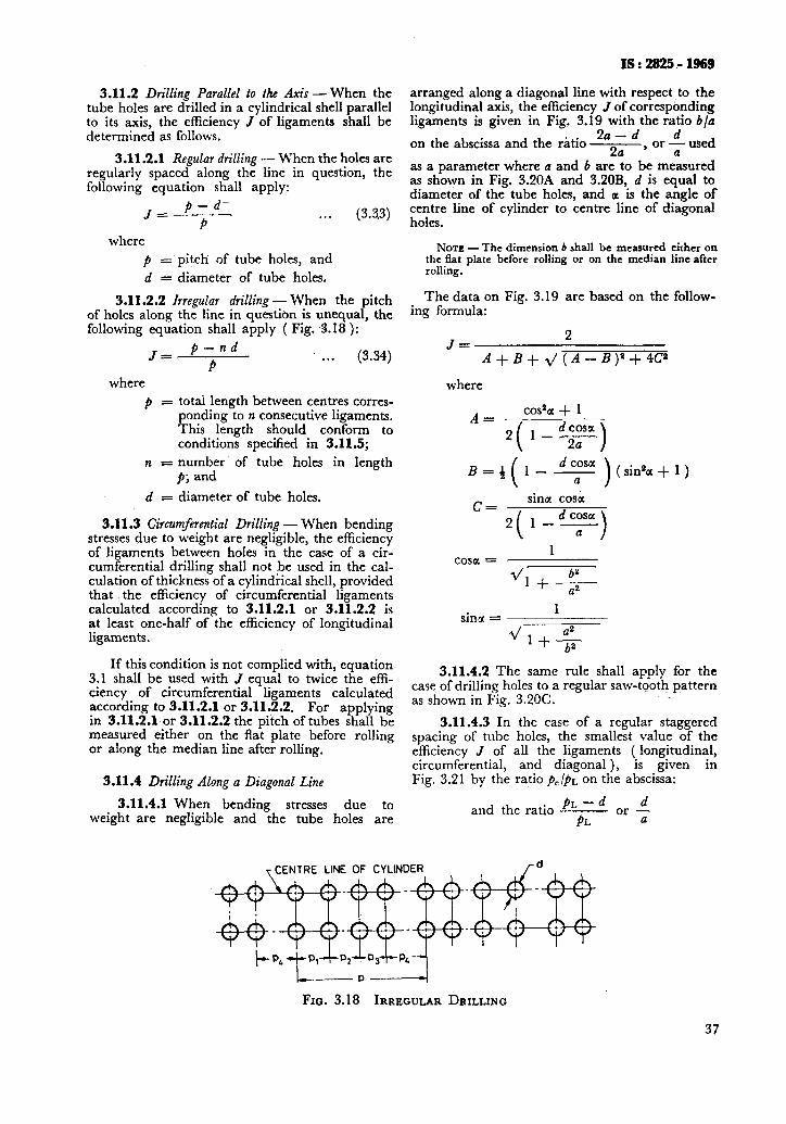
3.11.2 Drilling Parallel to the Axis - When the tube holes are drilled in a cylindrical shell parallel to its axis, the efficiency J of ligaments shall be determined as follows.
3.11.2.1 Regular drilling - When the holes are regularly spaced along the line in question, the following equation shall apply:
(3.93)
where
p = pitch of tube holes, and
d = diameter of tube holes.
3.11.2.2 Irregular drilling - When the pitch of holes along the line in question is unequal, the following equation shall apply ( Fig. 3.18 ):
. . (3.34)
where
P = totai length between centres corres- ponding to n consecutive ligaments. This length should conform to conditions specified in 3.11.5;
n = number of tube holes in length p; and
d = diameter of tube holes.
3.11.3 Circumferential Drilling - When bending stresses due to weight are negligible, the efficiency of ligaments between holes in the case of a cir- cumferential drilling shall not be used in the cal- culation of thickness of a cylindrical shell, provided that the efficiency of circumferential ligaments calculated according to 3.11.2.1 or 3.11.2.2 is at least one-half of the efficiency of longitudinal ligaments.
If this condition is not complied with, equation 3.1 shall be used with J equal to twice the effi- ciency of circumferential ligaments calculated according to 3.11.2.1 or 3.11.2.2. For applying in 3.11.2.1 or 3.11.2.2 the pitch of tubes shall be measured either on the flat plate before rolling or along the median line after rolling.
3.11.4 Drilling Along a Diagonal Line
3.11.4.1 When bending stresses due to weight are negligible and the tube holes are
IS : 282!5 ,- 1969
arranged along a diagonal line with respect to the longitudinal axis, the efficiency J of corresponding ligaments is given in Fig. 3.19 with the ratio b/n
on the abscissa and the ratio 2a - d
2a’ or 4 used
as a parameter where a and b are to be measured as shown in Fig. 3.2OA and 3.20B, d is equal to diameter of the tube holes, and a is the angle of centre line of cylinder to centre line of diagonal holes.
NOTE - The dimension b shall be measured either on the flat plate before rolling or on the median line after rolling.
The data on Fig. 3.19 are based on the follow- ing formula:
J= 2
A+B+2/(A-B))2+4C2
where
A= cos2a + 1
( sinea + 1 )
C= sina cosa
2 l-- (
d cosa a >
1 cosa =
d 1++
sina = ___ 1
2/l++
3.11.4.2 The same rule shall apply for the case of drilling holes to a regular saw-tooth pattern as shown in Fig. 3.2OC.
3.11.4.3 In the case of a regular staggered spacing of tube holes, the smallest value of the efficiency J of all the ligaments ( longitudinal, circumferential, and diagonal ), is given in Fig. 3.21 by the ratio p,/p~ on the abscissa:
and the ratio PL or - d
PL a
T CENTRE LINE OF CYLINDER /d
t_ P‘tP1+p,~~3+p4~
Fra. 3.18 IRREGULAR DRILLING
37
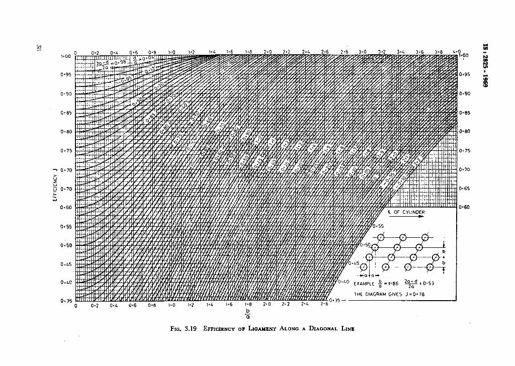
I-00
o-95
o-90
O-80
0.75
0.60
0.50
0.45
0.40
0.35
0 l-00
0.95
0.90
0.80
0.75
0.70
O-65
O-60

TCENTRE LINE Of CVLbNW?
d
FIG. 3.2OA REGULAR STAGGERING OF HOLES
,-CENTRE LINE OF CVLINDER r d
Aatalc
FIG. 3.20B SPACING O;E’~~OLICS ON A DIAGONAL
k-a-l ,-CENTRE LINE OF CYLINDER
FIG. 3.2OC REGULAR SAW TOOTH PATTSRN OF HOLES
where d = diameter of the tube holes,
PC = 2b = twice the distance between circumferential rows of holes,
PL = 2a = twice the distance between axial rows of holes, and
a = angle of centre line of cylinder to centre line of diagonal holes.
NOTE -The dimension PO shall be measured either on the Bat plate before rolling or on tbe median line after rolling. The data on Fig. 3.21 are based on the same formulae as Fig. 3.19.
3.11.5 Length Which Can be T&n into Con& akration for Drilling of Unequally Spaced Holes - Where holes are unequally spaced, the average ligament efficiency J ( used in the equation 3.1 ) shall be not more than what can be calculated
E using the equation ( 3.34 ) ] at any part over a
ength equal to the inside diameter of the shell ( maximum 1 500 mm ), or not more than l-25 times that obtained over a length equal to the
IS:2825-l%Y
inside radius ( maximum 750 mm ) taken at the least favourable part.
A lower efficiency calculated over a shorter length need not be considered.
If the unequally spaced holes form a symme- trical pattern over a length greater than the inside diameter of the shell with a maximum of 1 500 mm to give a greater efficiency over such length than is obtained above: then this greater effi- ciency may be used.
When holes spaced longitudinally along a drum are not in a straight line, the ‘equivalent longitudi- nal pitch for each spacing may be used in the application of the above rules. This equivalent pitch is obtained by multiplying the actual longi- tudinal pitch by the equivalent efficiency obtained from Fig. 3.19 for each spacing.
3.11.6 Tube plates in heat exchangers and pres- sure vessels shall be designed in accordance with the requirements of IS : 4503-1967*.
3.12 Jacketed Vessels
3.12.1 General - In addition to the require- ments stated elsewhere in this code, the design of jacketed vessels shall take into consideration the following factors:
4
b)
4
The inner vessel shall be designed to resist the full differential pressure that may exist under any operating conditions, including accidental vacuum in the inner vessel due to condensation of vapour contents. The local stresses that may be caused by differential expansion between the jacket and the jacketed vessel. Where the inner vessel is to operate under vacuum and the hydraulic test pressure for the jacket is correspondingly increased to test the inner vessel externally, care shall be taken that the jacket shell is designed to withstand this extra presstut.
3.12.2 Attachment - The jackets may be secured to the shell or ends or both by means of any suitable bolted or welded connections that is ap- propriate under the conditions of service ( set Fig. G.45 to G.59 and G.66 ).
3.12.3 Stqs - Stays may be used to secure the jacket to the jacketed vessel OF end. Wherever they are provided, the surfaces shall be calculated as flat stayed surfaces ( see 3.7 ). Stays which require perforation of the walls of the inner vessel shall not be used.
3.12.4 Outlets - Outlets which pass through the jacket space -or through recesses in jackets are common practice in the case of jacketed vessds. ( see Fig. G.60 to G.65 ).
3.12.5 Cot$ensation - Where reinforcement is required it shall be in accordance with the require- ments of 3.8.
+Sncrifir*tinn for A-.11 and tube type heat exchangers.
39
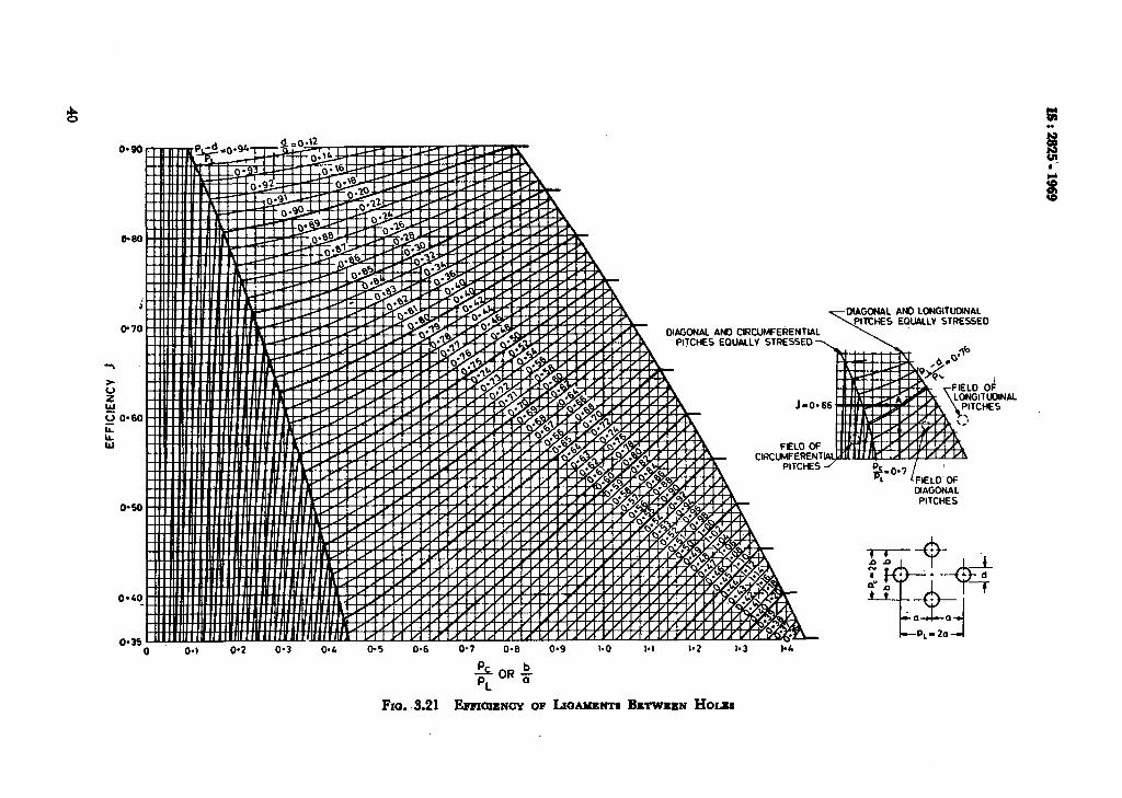
IS : 2825 - 1969
3.13 supports - (,See also Appendix C ).
3.13.1 Gmeral Design - The details of supports and internal structures shall conform to good practice. Care shall be taken that the tcmpera- ture gradients in external structures immediateiy adjacent to the shell do not produce stresses m excess of those laid down as permissible. If necessary, lagginq should be applied to limit the temperature gradlent to a value producing accept- able stresses. Loads arising from differential thermal expansion of the shell and the stipportitg structure in general shall not produce stresses m excess of those permitted by the respective speci- fication. External stays or internal framing that may be used for supporting internal parts may be used to provide a stiffening effect on the shell where exterior supporting structures, which do not form part of the vessel, should comply with the require- ments of IS : 8OO-1962*. When such supports are to be constructed in reinforced concrete they should comply with the requirements qf IS : 456-1964t.
In case of load carrying attachments welded directly to pressure parts, the material and the deposited weld metal shall be compatible with that of the pressure part.
3.13.2 Vertical Vessels
3.13.2.1 Bracket support - Where vertical ves- sels are supported on lugs or brackets attached to the shell (, Fig. 3.22A ), the supporting members under the. hearing attachments ihall preferably be as close to the shell as clearance for insulation will permit. The choice between a number of brackets and a ring girder will depend upon the conditions for each individual vessel.
3.13.2.2 Column support -- \‘ertical vessels sup- ported on a number of posts or columns may re- quire bracing or stiffening by means of a ring girder, internal partition or similar device in order to resist the force tending to buckle the vessel wall.
Where the value of the product is less than 16 x 106 ( mm2 deg ) the nominal compressive stress in the skirt should not exceed one-half of the yield stress of the skirt material at the temperature concerned or the value expressed by:
f max = 0.125 E.t cos o!
D . . . ( 3.35)
where
E = elastic modulus in kgf/mm* ( see Tables 3.1 to 3.4 ),
t = skirt thickness in mm,
D = skirt diameter in mm, and
a = half the top angle of the conical skirt ( for cylindrical skirts c0S a=1 ).
3.13.3 Horizontal Vessels
3.13.3.1 Horizontal vessels may be supported by means of saddles, equivalent leg supports or ring supports as shown in Fig. 3.22D and Fig. 3.223.
The welds attaching ring supports to the vessel should have a minimum leg length equal to the thickness of the thinner of the two parts being js”lned together.
3.13.3.2 Saddles may be used for vessels of which the wall is not too thin. Saddles should preferably extend over at least 120 degrees of the circumference of the vessel. For thin vessels it may be desirable to place the saddles at points near the ends of the vessel.
3.13.3.3 For thin-walled vessel whtre ex- cessive distortion due to the weight of the vessel may be expected, ring supports as shown in Fig. 3.223, are recommended. Where practicable, two ring supports only are preferable,
3.14 Internal Structures
3.13.2.3 Skirt sup,bort - This type of support as indicated in Fig. 3.22B and 3.22C should be not less than 7 mm thick in corroded condition. \\‘here the product of skirt diameter ( mm ), thickness ( mm ), and temperature at the top of the skirt above ambient ( deg ) exceeds 16 x 106 ( mm% deg ) account should be taken of the discontinuity stresses in both skirt and vessel induced by the temperature gradient in the upper section of the skirt. It is recom- mended that these stresses should be assessed by the criteria of 3.3.2.4 and Appendix C.
3.14.1 Internal structures and fittings shall be designed in accordance with good engineering practice and shall be arranged as far as practicable to avoid imposing local concentrated loads on the vessel.
3.14..2 Local loads from internal structures or from vessel contents shall be carried, where possible, by means of suitable stiffeners and or spacers directly to the vessel Supports and thus to the foundations without stressing the vessel walls or ends.
*Code of practice for use of structural steel in general building construction ( under revision ).
tCode of practice for plain and reinforc&d concrete for general building construction (second revision ).
3.14.3 Horizontal cylindrical vessels, which are provided with vertical external tower like exten- sions, should, where necessary, have the exten. sions supported independently of the vessel.
41
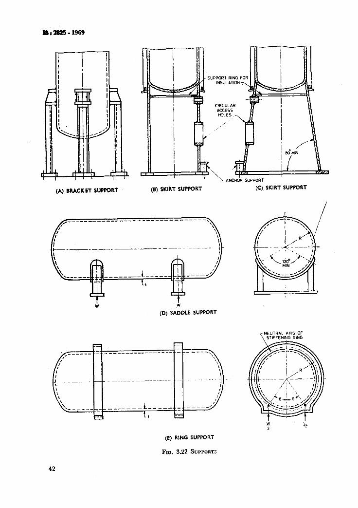
(A) BRACKET SUPPORT (B) SKIRT SUPPORT
I i ANCHOR SUPPORT
W
(0) SADDLE SUPPORT
(E) RING SUPPORT
FIG. 3.22 SUPPORT"
42
(C) SKIRT SUPPORT
NEUTRAL T
AXIS OF STIFFENING RING
4. FLANGE CALCULATIONS FOR NON-STANDARD FLANGES
4.1 General
4.1.1 The rules in this clause apply specifically to the design of bolted flanged connections and are to be used in conjunction with the applicable requirements of this standard.
These rules provide only for hydrostatic end loads and gasket seating. Where suitable, flanges complying with the appropriate Indian Standards ( see 3.10.2 ) shall be used and in such cases the calculations required by this -section need not be carried out.
4.1.2 The design of a flange involves the selec- tion of the gasket ( material, type and dimensions ), flange facing, bolting, hub proportions, flange width, flange thickness. Flange dimensions shall be such that the stresses in the flange, calculated in accordance with 4.7 do not exceed the values specified in 4.8.
4.1.3 Hub flanges shall not be made by machin- ing the hub directly from plate materials except subject to special approval by the purchaser.
4.1.4 The thickneii of flanges shall be deter- mined aa the greater required either by the o erating or by the bolting-up conditions and in a 1 cases, both conditions shall be calculated in P accordance with the following:
4
b)
Operating conditions - The operating condi- tions are the conditions required to resist the hydrostatic end force of the design pressure tending to part the joint, and to maintain on the gasket or joint-contact surface sufficient compression to assure a tight joint, all at the design temperature. The minimum load is a fimction of the design pressure, the gasket material, and the effective gasket or contact area to be kept tight under pressure ( equation 4.1 ), and determines one of the two requirements for the amount of the bolting, Aml. This load is also used for the design of the flange ( equation 4.3 ). Bolting-up conditions - The bolting-up conditions are the conditions existing when the gasket or joint-contact surface is seated by applying ai initial load with the bolts when assembling the joint, at atmospheric temperature and pressure. The minimum initial load considered to be adequate for proper seating is a function of the gasket material, and the effective gasket or contact area to be seated ( equation 4.1 ) and determines the other of the two require- ments for the amount of bolting, A,. For the design of the flange, this load is modified ( equation 4.4 ), to take account of the operating conditions, when these govern the amount of bolting required, Am as well as the amount of bolting actually provided, Ab.
Is:!uWi-1969
4.1.5 The following rules are based upon consi- derations of strength. In unusual circumstances consideration may be required to ensure freedom from leakage * .
4.2 Fasteners-It is recommended that bolts and studs have a nominal diHmeter of not less than 12 mm. If bolts or studs smaller than 12 mm are used, bolting material shall be of alloy steel. Precautions shall be taken to avoid over stressing smaller diameter bolts. Bolts and studs shall not have a thread of coarser pitch than 3 mm pitch except by special approval by the purchaser.
4.3 Classification of Flanges-For design purposes, flanged facings shall come .mder one of the
a)
b)
fdllowiig categoGes: jvawow-Faced Flanges - These are flanges where all the face contact area lies inside the circle enclosed by the bolt holes. They may be of the gasketed type or have face- to-face joints or a combination of both with or without a seal weld. The design rules for such flanges are given below. Wide-Faced Flanges - These are flanges with face contact area outside the circle enclosed by the bolt holes. The design rules for these flanges are not included ( see 4.1 ).
4.4 Flanges Subject to Internal Pressure ( Narrow-Faced Flanges ) - Ttle,ufnge desigrl, methods outlined in this together with 4.5, 4.6, 4.7 and 4.8 are apblicable to circular flanges under internal pressure.
The notation described below is used in the formulae for the design of flanges ( see aLro Fig. 4.1 ).
A = outside. diameter of flange or, where slotted holes extend to the outside of the flange, the diameter to the bottom of the slots, mm*.
Ab = actual total cross-sectional area of bolts at root of thread or section of least diameter under stress, mm2.
Am= total required cross-sectional a>ea of bolts, taken as the greater of Am1 and A m2, mm2.
A IIll = total cross-sectional area of bolts at root of thread or sectiog of least dia- meter under stress, required for the operating conditions, mm’ = w&/&.
A mr = total cross-sectional area of bolts at root of thread or section of least diameter under stress, required for gasket seating, mms = WmJ&.
B = inside diameter of flange, mm.
G = bolt pitch corre’ction factor
2/
bolt spacing 2 ( bolt diameter ) + t
*Rcfcrmce. Murray N,.W. and Stuart D.G. ‘ Bchaviour in large taper hub flange ‘. Symposium on premrc vascl research towards better design. Inst. Mech. E. 1961.
43
IS:2s25-1969
b = effective gasket or joint-contact-surface seating width, mm ( see Note in 4.5.2 ).
26 = effective gasket or joint-contact-surface pressure width, mm ( see 4.5 ).
b,, = basic gasket seating width, mm ( from Table 4.2 and Fig. 4.2 ).
C = bolt-circle diameter, mm
d = factor, for integral-type flanges 1
d= +- hogo /
for loose-type flanges
c = factor, for integral-type flanges j F 1
e=--- ho
for loose-type flanges
FI
j
b=ho 1 F = factor for integral-type flanges ( from
Fig. 4.4 ).
FL = factor for loose-type flanges ( from Fig. 4.6 ).
= hub stress-correction factor for integral flanges from Fig. 4.8 ( when greater than 1 this is the ratio of the stress in the small end of hub to the stress in the large end ) ; ( for values below limit of figure use f = 1 ).
G = diameter at location of gasket load reaction. Except as noted in sketch-A of Fig. 4.1, C is defined as follows ( see Fig. 4.2 ).
when b. < 6.3 mm, C = mean diameter of gasket contact face, mm:
when b > 6.3 mm, G = outside dia- meter of gasket contact face less 26, mm.
so = thickness of hub at small end, mm.
Sl = thickness of htib at back of flange, mm.
H = total hydrostatic end force, kgf =
-&- G2p.
Hn = hydrostatic end force on area inside of flange kgf = x/400 B2P.
HG = gasket load ( difference between flange design bolt load and total hydrostatic end force ), kgf HG = Wm, - H = HP for operating condition, HG = W for
HP =
HT =
h =
44
gasket seating condition.
total joint-contact-surface compression
load, kgf = PxbGmp
100 difference between total hydrostatic end force and the.hvdrostatic end force on area inside of flakge, kgf = H- HD,
hub length, mm.
hD = radial distance from the bolt circle, to the circle on which HD acts, as pres- cribed in 4.6, mm.
hG = radial distance from gasket load reaction to the bolt circle, mm
C-G = -. 2 *
ho = dBgo, mm
hT = radial distance from the bolt circle to the circle on which HT acts as pres- cribed in 4.6, mm.
X = ratio of outside diameter of flange to inside diameter of flange = A/B.
A = factor = [
te+ 1 t3 -
T +d 1 MJ = The greater of MOD or
nf*t, x SF, SFA
A&, = total moment acting upon the flange for gasket seating conditions, kgf*mm.
A&, = total moment acting on the flange for operating conditions, kgcmm.
m = gasket factor, obtained from Table 4.1 ( see Note in 5.4.2 ).
,V = width, mm, used to determine the basic gasket seating width bo, based upon the possible contact width of the gasket ( see Table 4.2 ).
p = design pressure, kgf/cm3. For flanges subject to external pressure, see 4.9.
R = radial distance from bolt circle to point of connection of hub and back of flange, mm ( integral and hub flanges ),
C-B -- Sl. 2
S, = nominal bolt stress at ambient tempe- rature, kgf/mm* ( see Table 4.5 ).
Sil = nominal bolt stress,at design tempera- ture, kgf/mm3 ( see Table 4.5 ).
SFA = nominal design stress for flange material at ambient temperature ( gasket seating conditions ), kgf/mm2 from Table 2 1 *.
SFo = nominal design stresses for flange material at design temperature
pagp;;5 condition ), kgf/mm* from . .
& = calculated longitudinal stress in hub, kgf/mm2.
s, = calculated radial stress in flange, kgfl mm2.
Sr = calculated tangential stress in flange, kgf/mm3.
7 = factor involving X ( from Fig. 4.3 ).
t = flange thickness, mm
*The above definitions are based on the assumption that the materials for the flange ring and neck are not signiii- candy different in their appropriate mechanical properties. If they are different, either the lower values should be used or special consideration given to the design.
U - factor involving X ( from Fig. 4.3 ).
Y = factor for integral-type flanges ( from Fig. 4.5 ).
V, = factor for loose-type flanges ( from Fig. 4.7 )
W = flange design bolt load, for th opera- ting conditions or gasket -seating, as may apply, kgf ( see 4.5.3 and 4.9 ).
W,, = minimum required bolt load for the operating conditions, kgf ( see 4.5 ).
W’& - minimum required bolt load for gasket seating, kgf ( see 4.5 ).
a, = width, in mm, used to determine the basic gasket seating width bo, based upon the contact width between the flange facing and the gasket ( see Table 4.2 ).
Y = factor involving X ( from Fig. 4.3 ).
y c gasket or joint-contact-surface unit seating load, kgf/mm’ ( see 4.5 ).
3 = factor involving X ( from Fig. 4.3 ).
4.4.1 Loose-Type Flanges - This type covers those designs where the method of attachment is not considered to give the mechanical strength equivalent of integral attachment, see Fig. 4.1 A, B, C and D for typical-loose-type flanges and the location of the loads and moments. Welds and other details of construction shall satisfl the dhnensional requirements given in Fig. 4.1 B, C and D.
4.4.2 Integral-Type Flanges-This type covers designs of such a nature that the flange and nozzle neck, vessel, or pipe wall is considered to be the equivalent of an integral structure, In welded construction, the nozzle neck, vessel, or pipe wall is considered to act as a hub. See Fig. 4.1 E, F, Fl, F2 and G for typical integral-type flanges and the location of the loads and moments. Welds and other details of construction shall satisfy the dimensional requirements given in Fig. 4.1 E, F, Fl, F2 and G.
4.43 Optional-T&e Flanges-This type covers designs where the attachment of the flange to the nozzle neck, vessel, or pipe wall is such that the assembly is considered to act as a unit, which shall lx calculated as an integral flange, except that for simplicity the designer may calculate the cons- truction as a loose-type flange provided none of the following values is exceeded:
go =16mm,; j: 300, p= 21 kgf/cm’, op-
erating temperature “= 365%.
( see Fig. 4.1 H, HI, H2 and J ) for typical o tional-type flanges. Welds and other details
I! construction shall satisfy the dimensional &uirements given in Fig. 4.1 H, Hl, H2 and J.
IS:m25-1%9
4.5 Bolt-
4.5.1 The minimum cross section of the bolting provided shall be adequate:
a) to prevent leakage under the operating conditions, and
b) to seat the gasket under the bolting-up condition.
4.5.1 .l Opcrcrting condition - To retain a leak- tight joint under pressure the minimum bolting required W,,,, shall be given by equation 4.1:
Klr - H+H, . . . (4.1)
where H = x/400 C”p for gasket flanges
2 x bGmj HP- 1oo
4.5.1.2 Bolting-u& cona%ion - For gasket seat- ing the minimum bolt load required W,, shall be:
W,=,bGy . . . (4.2)
4.5.2 The minimum required bolt area shall be adequate to provide the greater of the bolt loads determined by equations 4.1 and 4.2 above. This area shall be calculated by using bolt stresses at the temperatures appropriate to the two condi- tions:
that is, A, is the greater of Am1 or A, . . . (4.3) where Am1 = Wml/&,
and Am8 = Wmz/&
The actual bolt area provided ( Ab ) shall be not less than Am, and, to prevent damage to the gasket during bolting-up, shall not exceed the value given by:
A _2xyGfl b---x-- . . . (4.4)
If it is not-practicable to adjust the actual bolt area to meet the latter requirement the whole procedure shall be repeated with a suitably modi- fied gasket.
NOTE - See Table 4.1, Table 4.2 and Fig. 4.2 for mggecd valuu dm, b andy.
The method used to tighten the bolts shall ensure that the design bolt stresses are attained.
4.5.3 Design bolt load W (flanges and bolted ends )
Loads used in the design of the flange shall be :
For operating condition, W = Wmt
For bolting-up condition, W = Ani+Ab x S 2 l
NOTE- For w mbjcct to cxUrnal preuure sea 4.9.
45
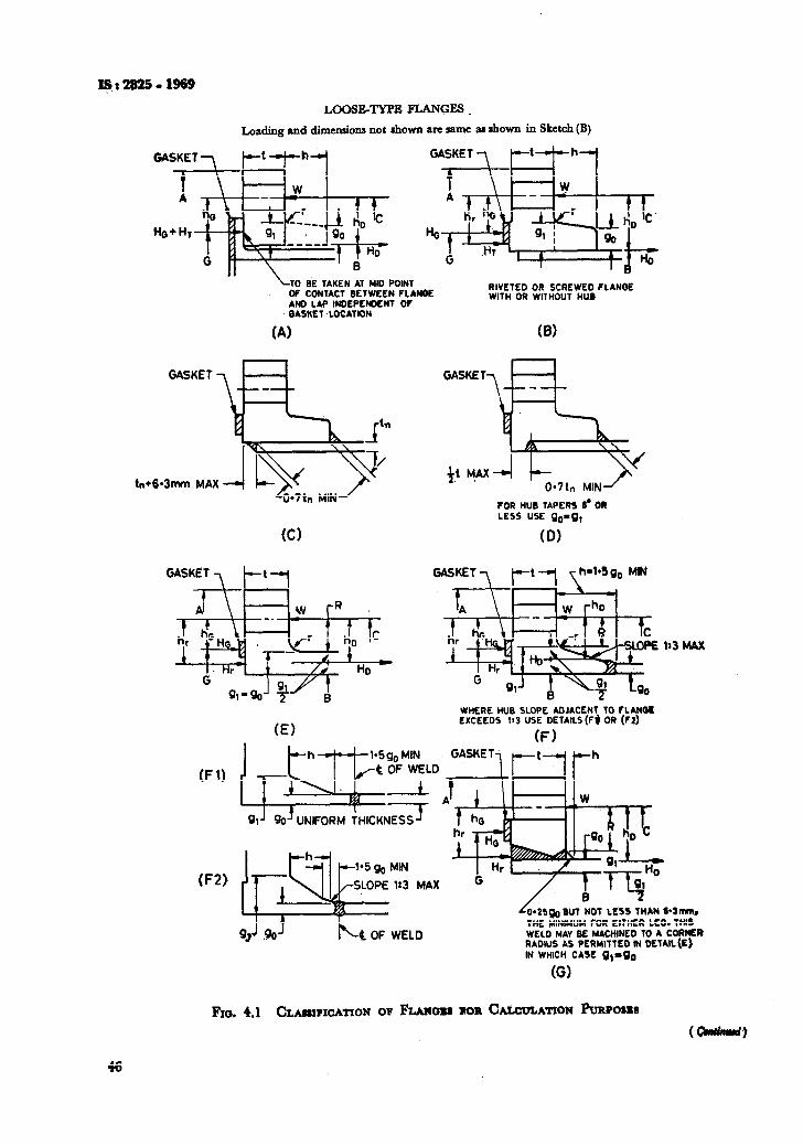
LOOSE-TYPE FLANGES
Loading and dimensions not shown arc same BI shown in Sketch (B)
BE TAKEN AT MID POINT OF CONTACT BETWEEN FLANOE AND LAP INDEPENDENT OF OASKET-LOCATION
RIVETED OR SCREWED FLANQE WITH OR WITHOUT HUB
GASKET
tn+6*3mtn. MAX
w
GASKET
% +,t +x4
0*7tn MIN
FOR HUB TAPIRS 6’ OR
LESS USE go-g,
(0)
GASKET -‘I
I Al w p
f c hD
HD C
(El
WHERE HUB SLOPE ADJACENT To FLANO~ EXCEEDS I:3 USE DElAILS(F$ OR (FZ)
(F) GASKET7 p-t-“1 I’h
O= 1)
F2)
91 J B0’ UNIFORM THICKNESS J
MAX
b- C OF WELD
42s~g BUT NOT LESS THAN 64mmn
THE MINIMUM FOR EITHER LEO. THIS WELD MAY BE MACHINED TO A CORNER RADIUS AS PERMITTED I?4 DETAIL(E)
. - IN WHICH CASE g,mgD
(G)
FIG. 4.1 CLM~$FIOATION OF FLMOU ROR C~CULATION hpOSRS
(CIIJlmud)
46
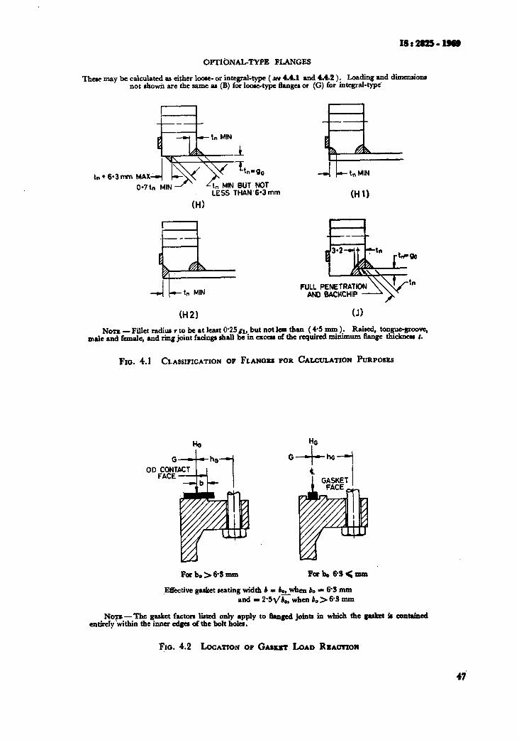
OPTIbNAL-TYPE FLANGES
These may be calculated aa either locac- or integral-type ( SCI 4.4.1 and 4.4.2 ). Loading and dimcnsiom not showii are the same PI (B) for looetype 6angu or (G) for integral-type’
b l 6*3mn
LESS THAN.603 mm
(HI
(H2)
(HII
tn
(J)
NOTE -Fillet radiur I to be at l&t @25 gl, but not laa than ( +5 mm ). Raked, tongue-6rcovq male and fanale, and ring joint facinga shall be in cxccn of the required minimum Range thkknas :.
FIG. 4.1 CLASSIFICATION OF FLANCUU FOR CALCULATION PURPOSES
J?.tTective gasket seating width b = bo,when bo * 63 mm and-2*5~b,,,whenb.>6-Smm
NW -The gasket factora liaed only apply to #at@ jointa in which the gasket t contained attWy within the itma edgea afthe bolt holes.
Fm. 4.2 bCATION OF GASKST LOAD Ra~cmon
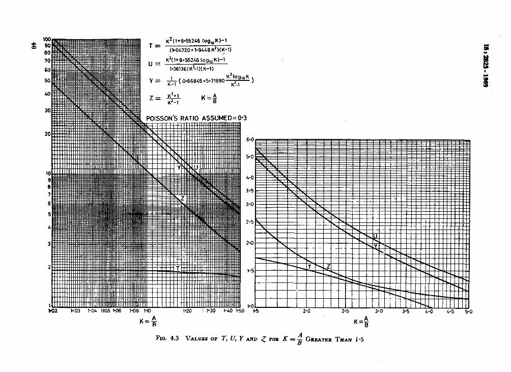
T K*(l+8*55246 log,K)-1
= W04720+1~9U6K2)(~-l)
u = K2(1+6*5524610g,,K)-1
1*36136(K'-l)(K-1)
Y = & (066845+5*71690* )
Kc;
6.0
K=A B
Fro. 4.3 VALUSS OF 1; LJ, Y A
2.5
I I I I n _^ I I I I I I I I I lIllll~IIllIlIIIJ .._ ..^ ^_ ._ .- __
1’3 L’U L’3 J’U
K+
tND 5 FOR K=$ GRRATRR THAN 1.5
.wJ 4-o 4.5 5-u
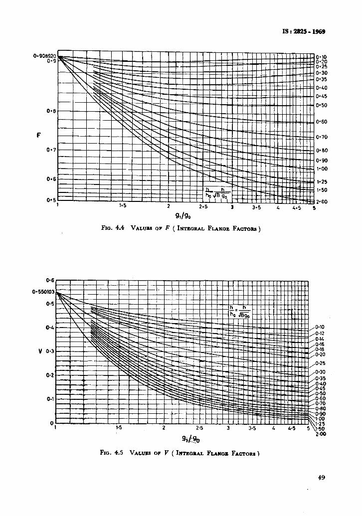
IS : 2825 - 1969
0.6 r I I I I
‘**lo O*?O 0*25 0*30 0*35
o-40
o-45
0*50
0*60
o* 70
0*60
O-90
v o-3 E 0120
O-25
Fm. 4.4 VALW OF F ( INTWRAL FLANGE FACTORS )
PO0
1.25
1.50
0.6
o-30 0.35 0.40 0.45 O-50 ^ “^
FIG. 4.5 VALIJSS OP Y ( INTE~EAL FLANIX FACTORS )
49
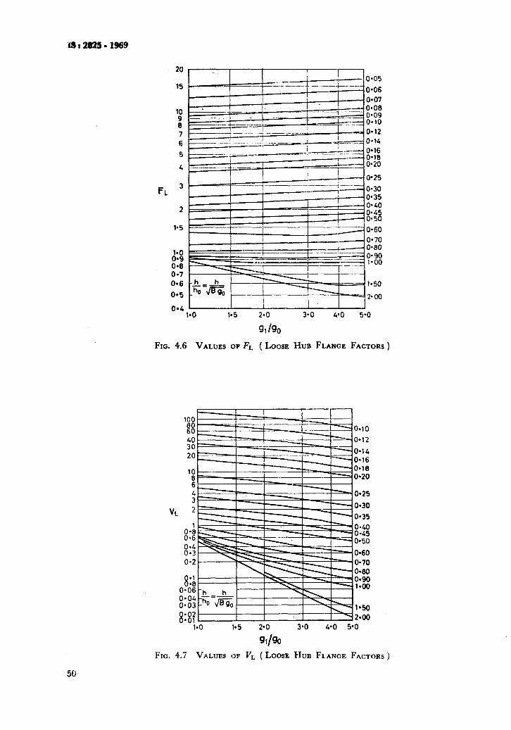
r15:2825-1969
'90 8 7 6
5
4
--- , -L---c?T _-.i----- 0.16 ~__...~._.. _
I--, ~_._ -_. ._ o,,8
r I c--- ..__ i
z 0.20 I I
FL 3
2
0.25
0*30 0.35 0.40 0945 0.50
0.60
0.70 0.80
?% .
@4< I.0 1.5 2.0 3.0 4*0 5*0
%Igo
FIG. 4.6 VALUES OF FL (LOOSE HUB FLANGE FACTORS)
100 8 0.10
ioo O=l?
20 0.14 O-16
'! 0*18 0920
6
i 0*25
VL 2 0*30
0*35 1
8:; 0*40 o-45
8:'; 0*50
O-60 o-2 o-70
O-60 01
0.i: 8 KE .
KG gls: 1950 2*00
l*O 1*5 30 3*0 4*0 5'0
%/eo
FIG. 4.7 VALUES QF V, (LOOSE HUB FLANGE FACTORS j
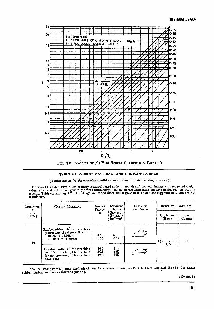
IS:28!I5-l%!I
25 z.05
20 O*lO
o-15 0*20
15 I
0.25 0*30 o-35
o-70 5
O-60 4
10 o-40
9 o-45
6 o-50
7 O-60
0.90
3 l-00
2.5
1.10 2
l-20
1.5 1'30
1 1 1*5 2 3 4 5
91 /go Fxc. 4.8 VA&U OF f ( HUB STRESS CORRECTION FACTOR )
TABLE 4.1 GASKET MATEKIALS AND CONTACT FACINGS
[ Gasket factors (m) for operating conditions and minimum design seating stress (y ) ]
Nora - This table gives a list of many commonly used gasket materials and contact facings with suggested design values of m and y that have generally proved satisfactory in actual service when using effective gasket seating width j given in Table 4.2 and Fig. 4.2. The design values and other detads gtven 111 thus table are suggested only and are not mandatory.
DI~~~NSI~N N
(Z)
10
GASKET MATERIAL
Rubber without fabric or a high percentage of asbestos fibre:
Below 70 IRHD* 70 IRHD* or higher
Asbestos with a] 3.2 mm thick suitable binder 1 1% mm thick for the operating )0*8 mm thick conditions J’
__
.-
-
GASKET MINIMW FACIQR DESION
m SEATING
ST==% * kgf/mm’
-Y
6.50 0 l-00 0.14
--
2.00 1.12 2’75 260 3.50 457
d
Y --
--
-
~.. _.__- ~-
SKETCHES REFER TO TABLE 4.2 AND NOTES I
i Use Facing / Sketch
: l(a,4b,jc,d),
&zd
-
_-
-
Use Column
II
*&t IS : 3488 ( Part II 1-1965 Methods of test for vulcanized rubbers. * Part II Hardness; and IS : 638-1965 Sheet rubber jointing and rubber insertion jointing.
( continh~)
51
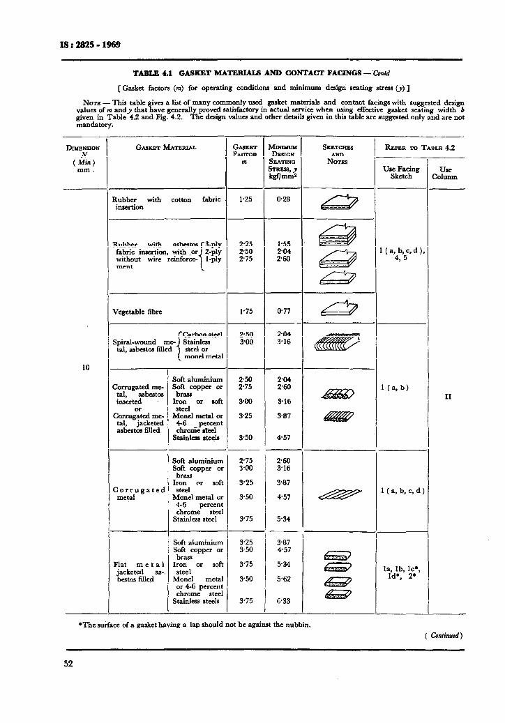
Is: 2825-1969
TABLE 4.1 GASKET MATERIALS AND CONTACT FACINGS - Contd
[Gasket factors (m) for operating conditions and minimum design seating stress (y) ]
NOTE - This table gives a list of many commonly used gasket materials and contact facings with suggested design values of m andy that have generally proved satisfactory in actual service when using effective gasket seating width 6 given in Table 4.2 and Fig. 4.2. The design values and other details given in this table are suggested only and are not mandatory.
GASKET FACXOR
m
DIMENSION Jv
(Mill) mm.
REFER TO TABLE 4.2 p-
“s;kzcg Use Column
MINIMUM DESIGN
SJZATINQ
&Zl~
0.28
GMICET MATERIN.
Rubber with cotton fabric insertion
1.25
Rubber with asbestos [B-ply fabric insertion, with ,or 2-ply without wire reinforce- l-Ply ment
2’25 2’50 2’75
1’75
1.55 204 268
877
204 3.16
1 ( a,4b,5c, d ), ,
Vegetable fibre
tal, asbestos filled
10 -
--
-_
-
Soft aluminium S;F;opper or
Iron or soft steel
Monel metal or 46 percent chrome steel
Stainless steels
;:%i ;:it
3-00 316
325 387
350 457
Corrugated me- tal, asbestos inserted
Corrug~ed me- tal, jacketed asbestos filled
1 (a, b) II
Soft aluminium S;r=zopper or
Iron or soft steel
Monel metal or 4-6 percent chrome steel
Stainless steel
Soft aluminium Soft copper or brass
Iron or soft steel
Monel metal or 46 percent chrome steel
Stainless steels
--
275 268 388 316
325 387
3.50 457
3’75 534
3.25 387 3.50 457
3.75 534
350 5.62
3.75 I - 633
Corrugated metal
1 ( a, b, c, d 1
Flat met a 1 jacketed as- bestos filled
la, lb, 119, Id+, 2f
*The surface of a gasket having a lap should not be against the nubbin.
52
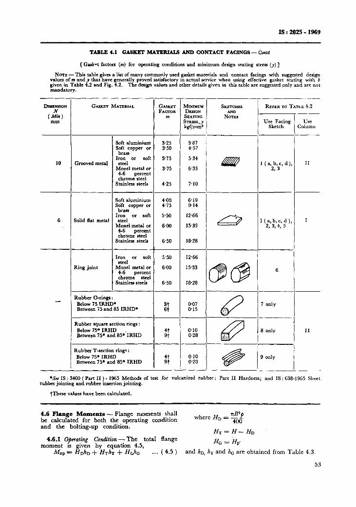
IS : 2825 - 1969
TABLE 4.1 GASKET MATERIALS AND CONTACT FACINGS - Confd
[Gasket factors (m) for operating conditions and minimum design seating stress (y) ]
NOTE - This table gives a list of many commonly used gasket materials and contact facings with suggested design values of tn andy that have generally proved satisfactory in actual service when using effective gasket seating with b given in Table 4.2 and Fig. 4.2. mandatory.
The de&n values and other details given in this table are suggested only and are not
--_
DnreNs10~ GASKET ~~ATERLAL GASKET N FMTOR
(Mitt) m
-
_-
MINIMUH DESIGN SEATING ST=%J kgf/mm’
3.25 3.87 3.50 4.57
3.75 5.34
3.75 6.33
4.25 7.10
400 6.19 475 9.14
5.50 12.66
6.00 15.33
6.50 l&28
5.50 1266
6.00 15.33
6.50 l&28
0.07 @I5
_ -
__
-
0.10 0.28
@IO 0.211
-
I
, I
-_
!
_..
__
_-
_-
--
-
SKETCHES
N%~s
REFER M TABLE 4.2 -
-r
_-
Use Column
10 Grooved meta!
6 Solid flat metal
Use Facing Sketch
Soft aluminium S;Fa;pper or
Iron or soft steel
Monel metal or 4-6 percent chrome steel
Stainless steels
Soft aluminium Sdft copper or
brass Iron or soft
steel Monel metal or
4-6 percent chrome steel
Stainless steels
Iron or soft steel
Monel metal or 4-6 percent chrome steel
Stainless steels
1 ( a, b, c, d 1, 2, 3
II
l(a,b,c,d), 2, 334, 5
I
6
7 only
8 only II
Ring joint
Rubber O-rings : Below 75 ItiD* Between 75 and 85 IRHD* Q :’
:‘::J ‘..
67 +: . . . . . S’:.<.\.
Rubber square section rings : Below 75. IRHD Between 75’ and 85*‘IRHD
Rubber T-section ring.* : Below 75’ IRHD Between 75’ and 855 IRHD @ li..
9 only
-
*See IS : 3400 ( Part II ) - 1965 Methods of test for vulcanized rubber : Part II Hardness; and IS: 638-1965 Sheet rubber jointing and rubber insertion jointing.
fThese values have been calculated.
4.6 Flange Moments - Flange moments shall be calculated fir both the operating condition
where HD = =$$$f
and the bolting-up condition. HT=H-HD
4.6.1 Operating Condition - The total flange moment is given by equation 4.5,
HG z-H,-
MOP = HD~~D + HT~T + H&c . . . (4.5) and hD, hx and hc are obtained from Table 4.3.
53
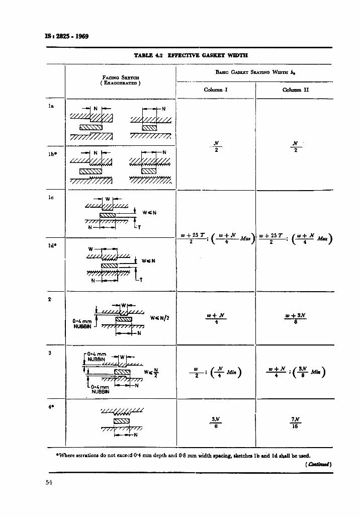
TABLE 4.2 EFFEGTIVE GASKET WIDTH
la
lb+
lc
Id*
4
3
4.
FACINO SKETCH ( ExaooERATED )
b--d-N
NUB&N
BASIC GASKET &%~INO WIDTH be
N 2
w+25T 2 ;
w+N Mary 4 ,
w+N 4
+; (+ Min)
3N .v 6
N 2
w+25T 2 ;
W-4-3N a
w+N ; 4 (
-y Min )
7N -ii-
*Where wrationa do not exceed @4 mm depth and O-8 mm &dth #pacing, &et&u lb &d Id shall be wed.
(-1
54
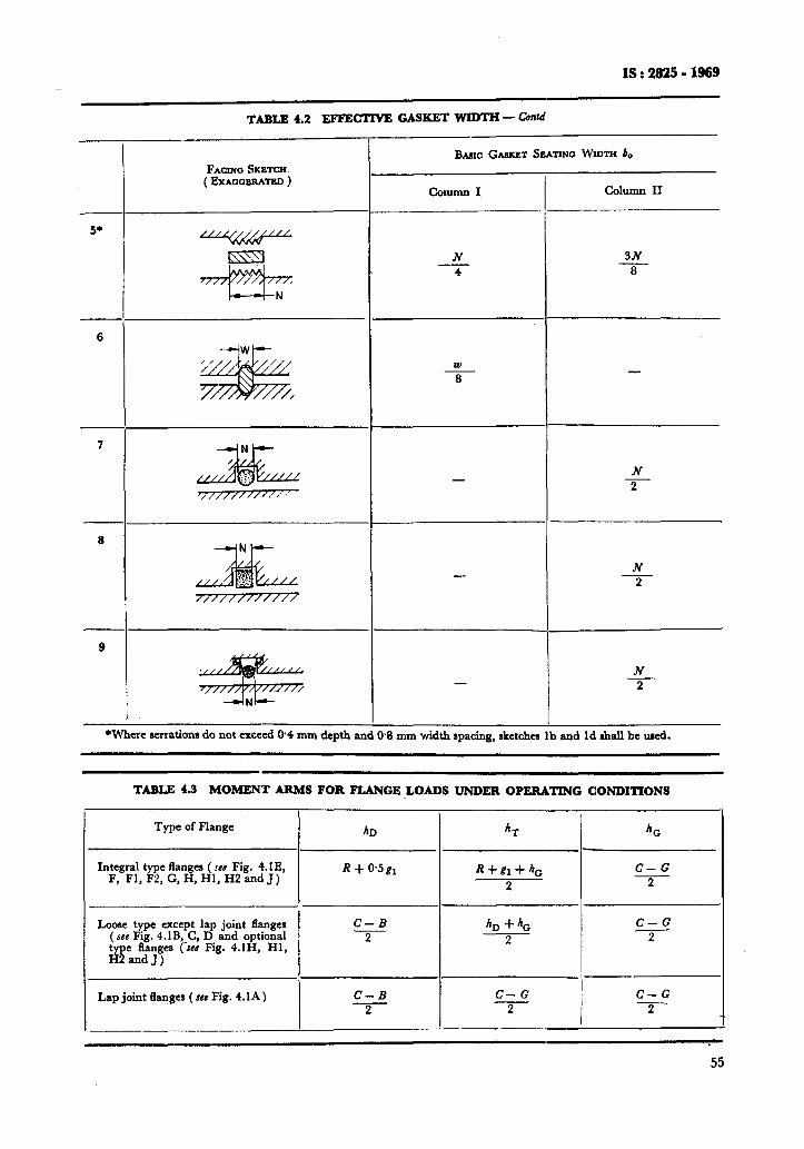
1s : 2825 - 1969
TABLE 4.2 EFFECT GASKET WIDTH - Chid
FACING SRBTCH ( EXAOQERATED )
5+
6
-+iWi--
7
IT///////‘*‘/,,
8
,,,x,,,
9
*Where serrationr do not exceed @4 mm depth nu
Bmc GASKKT SEATINQ WIDTH b.
N 1 - 3N
4 8
N - 2
-
N - 2
-
Ml mm width spacing, aketchea ;b and Id &all be used.
TABLE 4.3 MOMENT ARMS FOR FLANGE LOADS UNDER OPERATING CONDITIONS
Type of Flange
Integral type flanges ( ~8 Fig. 4.1 E, F, Fl, F2, G, H, HI, H2 and J)
hD
R + 0.5 81
-
6-r
R+gl+h,
2
h,
C-G 2
Loose type except lap joint flanges ( SC@ Fig. 4.1B,_C, D and optional type Ranges (see Fig. 4.1H, Hl, H2and J)
C-B C-G
2 b + hc
2 2
iP
Lap joint langes ( JM Fig. 4.1A )
---
C-B C-G
I
C-G
2 2 2
55
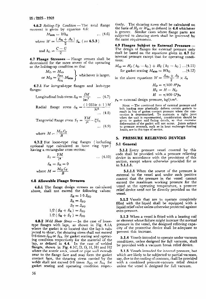
IS : 2825 - 1969
4.6.2 Bolting-Up Conditian -The total flange moment is given by equation 4.6:
Matm = Whc . . . (4.6)
where W - (Am ; Ab ) s,, ( see 4.5.3 )
C-G and hc = --
2
4.7 Flange Stresses - Flange stresses shall be determined for the more severe of the operating or the bolting-up condition so that
Mn = Mm 7 -. SF0 or MO = - Matm
whichever is larger.
SFA
4.7.1 For integral-type flanges and hub-type flanges:
Longitudinal hub stress Su = ,- h9i2
. . . (4.7)
( 1*333te _1- 1 )M‘ Radial flange stress Sa = __
At2 . . . (4.8)
Tangential flange stress Sr = Ff-/SSa
. . . (4.9)
where M = A*
4.7.2 For loose-type ring flanges ( including optional type calculated as loose ring type ) having a rectangular cross section:
S =yM T ta ..*
s, = s, = 0
MO CF where M = --_- B
4.8 Allowable Flange Stresses
4.9.1 The flange design stresses as calculated above, shall not exceed the following values:
SH = 1 J5 s,,
SR = SF0
ST = SF,
l/2 (SH •t SR) =sFO
l/2(sH+sT) =sFO
4.8.2 Weld Shear Stress - In the case of loose- type flanges with laps, as shown in Fig. 4.1A where the gasket is so located that the lap is sub- jected to shear, the shearing stress shall not exceed O-8 times SF0 or &A for gasket seating and operat- ing condition respectively for the material of the lap, as defined in 4.4. In the case of welded flanges, shown in Fig. 4.1 C, D, G, H, Hl and H2 where the nozzle neck, vessel or pipe wall extends near to the flange face and may form the gasket contact face, the shearing stress carried by the welds shall not exceed 0.8 times Sro or SF, for gasket seating and operating condition respec-
56
tively. The shearing srress shall be calculated on the basis of HP or W,, as defined in 4.4 whichever is greater. Similar cases where flange parts are subjected to shearing stress shall be governed by the same requirements.
4.9 Flanges Subject to External Pressure - The’ design of flanges for external pressure only shall be based on the equations given in 4.7 for internal pressure except that for operating condi- tions:
A&o, = HD(hD-hhc)+HT(hT-hc)...(4.11)
for gasket seating Matm = WhG . ..(4.12)
in the above equations W = &, + Ab x
2 s
B
HD = x/400 B2pe
HT=H-HD
H = x/400 G2pB
pe = external design pressure, kgf/cm2.
NOTE - The combined force of external pressure and bolt loading may plastically deform certain gaskets to result in loss of gasket contact pressure when the con- nection is depressurized. To maintain a tight joint when the unit is repressurized, consideration should be given to gasket and facing details, so that excessive deformation of the gasket will not occur. Joints subject to pressure reversals, such as in heat exchanger floating heads, are in this type of service.
5. PRESSURE RELIEVING DEVICES
5.1 General
5.1.1 Every pressure vessel covered by this code shall be provided with, a pressure relieving device in accordance with the provisions of this section, except where otherwise provided for as in 5.1.1.1.
5.1.1.1 When the source of the pressure. is external to the vessel and under such positive control that the pressure in the vessel cannot exceed the maximum working pressure for the vessel at the operating temperature, a pressure relief device need not be directly provided on the vessel.
5.1.2 Vessels that are to operate completely filled with the liquid shall be equipped with a liquid reliefvalve unless otherwise protected against over-pressure.
5.1.3 When a vessel is fitted with a heating coil or element whose failure might increase the normal pressure in the vessel, the designed relieving capa- city of the protective device shall be adequate to prevent this increase.
5.1.4 Vessels intended to operate under vacuum conditions, unless designed for full vacuum, shall be provided with a vacuum break relief device.
5.1.5 Vessels intended for internal pressure, but which are likely to be subjected to partial vacuum, say, due to the cooling of contents, shall be provided with a combined pressure-vacuum relief device unless the vessel is designed for full vacuum.
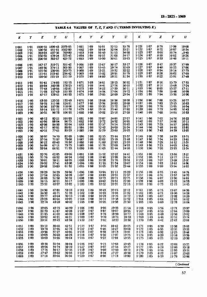
TABLEI. VALUES OF r,Z, YAND U(TJUUW6INVOLVINGK)
R l- z Y u K I Z Y u Ii- I z Y u
1000.50
g:: 250% 200-50
1899.43 207885 l-061 1.89 16.91 32.55 35.78 l-121 1.87 8-79 951.81 1052.80 1.062 l-89 16-64 32.04 3521 l-122 1.87 8.72 637.56 700-80 I.063 1.89 1640 31.55 34.68 I.123 I.87 8% 478-04 525.45 l-064 l-89 16.15 31.08 34-17 1.124 l-87 8.59 383.67 42 l-72 l-065 1<89 1590 30-61 33.65 1.125 1.87 853
30-17 33.17 I.126 l-117 8.47 29-74 32.69 I.127 l-87 8.40 2932 32.22 I.128 1.87 8-34 28.91 31.79 l-129 l-87 8-28 28.51 31.34 l-130 1.87 8.22
1790 1868 16.87 16.54 16-74 ,&40 1662 18.26 16.49 l&11
16.37 ::*z l&25 *
16-14 17-73 16.02 17-60 15.91 17.48
1 ~.-I(1 1d ,.a !7-35 15.68 17.24 15-57 17-11
154.6 15.36 :t: .
15.26 1677 1515 16.65 15.05 16.54 14.95 16-43 14.86 16-35
1476 14-66 :t’:: *
1457 1448 :t:: * 14-39 1583
1429 l!Y71 1420 15-61 1412 15-51 1403 15.4s 13.95 15.34
13.86 152? 13-77 15-14 13.69 15.05 13.61 13-54 KE *
13.45 14-78 13.37 14-70 13.30 1461 13.22 1453 ;3.;5 14.43
13.07 14-36 13al 14-28 12.92 14-20 12.85 14-12 12.78 14-04
12.71 13.97 !2*64 ! 3.69 12.58 13.82 12.51 13.74 12.43 13.66
12.38 13.60 12.31 13.53 12.25 1346 12.18 13.39 12.10 13.30
12.06 13.25 12.00 13.18 11.93 13.11 Il.87 13.05 1 l-79 12.96
la01 l-91 ::Ez 1.91
:‘tf ::z - l-91
::z :I .
l-008 l-91
::E! 1.91 1.91
I’“1 1 l -.-.*’ i-9:
::8y l-91 l-91
::x ::z
% ::g
fflcl~ f-2 a*“.” _*__ l-020 1.90
I-021 1.022 ;:g
1-o23 :‘z :%f * l-90
:% la90 l-028 ::g
tzt ::g
1.031 190 1.032 1.90
1*o33 :z FE * 190
l-036 1.90 I.037 1.90 l-038 1.90 l-039 l-90 :_Ogj !*90
la1 1.90
lTM2 :‘z 1.043 * l-044 1.90 l-045 1.90
f:E l-90 _ __. 190 1.048 1.90 :1a49 1.90 I.050 l-89
1.051 1.89
:::z l-89 1.89
1.054 l-89 i-055 1.89
l-056 1.89 1.057 l-89 l-058 l-89 1.059 1.89 la60 1.89
l-066 1.89 l-067 l-89 l-068 1.89
GE ::z
,.n,, 1 “IS !*89 1.072 1.89 l-073 1.89 l-074 l-88 1.075 1.88
15.67 15-45
:P;; 14.80
!+6! 28.13 14-41 27.76
16717 319-71 351.42 143% 174.11 301.30 125-50 239-95 263-75 111.61 213.40 23442 100-50 192.19 211.19
174.83 !92!3 -160.38 176.25 148% 162.81 137-69 151.30 128-61 141.33
I.111 a I.#. !*8? &!6 l-132 1.87 8-11 l-133 1.86 805 I.134 1.86 7-99 l-135 1.86 7.94
9:-e:
t% 71.93 67.17
14-22 14tM
27-39 3@11 27.04 2972 26-69 2934
26.36 28.98 28.69
13-85
6500 120.56 13249 59.33 111.98 12481 56% 107.36 118.00 53-14 101.72 111-78 50.51 96-73 106.30
l-076 1.88 13-68 l-077 1.88 13.56 1.078 1.88 13-35 1.079 1.86 13-18
-. _. 26-03 __ __ 25.72 28-27 25.40 27.92 25.10 27.59
1.136 l-86 7.88 1.137 1.86 7.83 l-138 1.86 7.78 1.139 1.86 7-73 1.140 1.86 7.68 la80 l-88 13.02
1.081 l-88 1.082 l-88 1.083 l-88 1.084 1.88 l-085 1.88
12.87 24-81 12.72 24-52 12.57 24.24 12.43 24m 12.29 2369
27.27 26.95 26.65 2634 2605,
l-141 l-86 7.62 1.142 1.86 7-57
48.12 4596
:E 40.51
1.143 l-86 7.53 1.144 1.86 748 i.145 1.86 7.43
1.146 l-86 7.38 1.147 1.86 7.34 1.148 1.86 7-29 1.149 1.86 7-25 1.150 1:86 7-20
3897 37.54 36-22 3499 33-84
74-70 71.97 KEz . 69-43 76-30 67.11 7375 64.91 71.33
32.76 62.85 69-06 31.76 60-92 66’94 30-81 59-11 63-95 2992 57.41 63.08 29-08 55-80 61.32
:%I; 11-89 11.76 1 l-63
2344 2557 23.18 2948 22.93 25.20 22.68 24-93 2244 2466
::i;: :%I 1.093 l-88 l-094 1.88 1.095 1.88
Il.52 1140
::% 11.05
22.22 21-99 21.76 21.54 21.32
10.94 21.11 1083 2091 10-73 20.71 1062 20-51 !@52 20.31
10.43 20.15
2441 l-151 1.86 7.16 2416 1:152 1.86 7.11 23.91 l-153 1.86 7,07 23-67 1.154 1.86 7.03 2344 1.155 l-86 6.99
5429 5966 52-85 58.08 51.50 56.59 50-21 55.17 43.97 53.82
yl9; yg
1.098 1.88 1.099 pfl !*!OO I.“”
23.20
EZ 22.39 22*!8
1.156 l-86 6.95 1.157 l-86 6-91 1.158 l-86 6.87 1.159 1.86 6.83 !.I60 I.66 6.79
2490 24-32 23.77 2323 22-74
47.81
2:;: 55% 5015
M64 49.05 4369 4802
42.75 46.99 41.67 46.03 41.02 45.09 40-21 44.21 39.43 43.34
38.68 42.51 37.96 41.73 37.27 40.96 36.60 4023 3596 3964
l-101 1.88 22.12 1.161 1.85 6.75 21.92 l-162 l-85 6-71 21.72 1.163 l-85 6.67 21.52 1.164 1.85 6-64 21.30 1.165 1.85 6.60
1.102 1.88 10.33 1994 1.103 1.88 10-23 1976 1.104 1.88 1.105 l-88
l-106 1.88 1.107 1.87 y; yE$
I.110 l-87
10.14 1005
19.58 1938
996 987 9.78 970 9-62
19.33 21.14 1.166 l-85 6.56 1907 2096 1.167 1.85 6.53 18.90 20.77 1.168 1.85 6.49 18.74 20.59 1.169 1.85 6.46 18.55 20.38 1.170 1.85 6.42
9.54 18.42 9-46 18.27 938 18.13 9.30 17.97 9.22 17.81
2025 1.171 1.85 6.39 2008 1.172 1.85 6.35 19-91 1.173 1.85 6.32 19-75 1.174 1.85 6-29 1955 1.175 l-85 6.25
2205 21.79 21.35 20.92 20.51
1.111 1.87 l-112 l-87 l-113 1.87 1.114 1.87 1.115 l-87
20.12 19-74 1938 1903 18.69
18.38 18.06 17.76 17-47 17-18
35.34 38.84 3474 38.19 34-17 37.56
x 36-95 3634
l-116 1.87 1. “s 7 4.87 1.11 1.87 l-119 I.87 l-120 l-87
9-15 9.07 900
17.68 1943 17.54 1927 17.40 19.12 17.27 18.98 17.13 18.80
1.176 1.85 622 1.177 1.85 6.19 1.178 1.85 6-16 1.179 l-85 6-13 1.180 1.85 6.10
8.94 8.86
( Continued
57
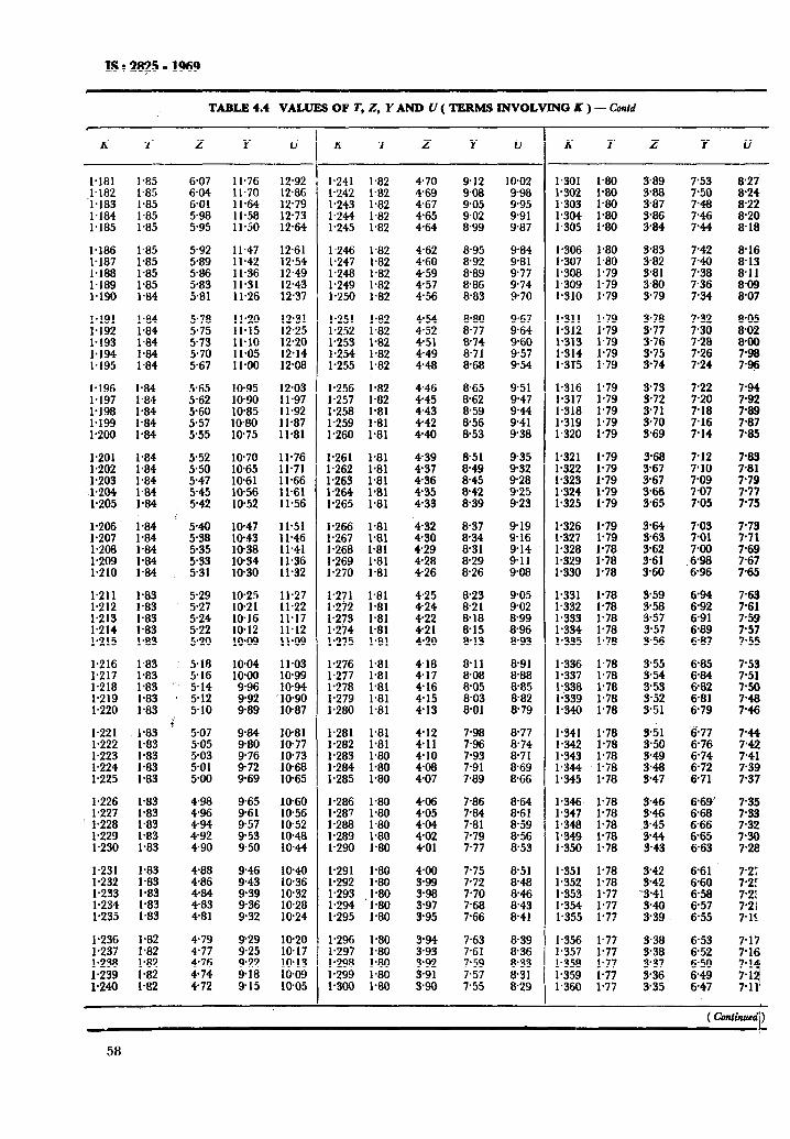
IS : 2825 - 1969
TABLE 4.4 VALUES OF Z’, Z, Y AND V ( TERMS INVOLVING K ) - Confd
c
K I z Y V
1.181 1.85 1.182 1.85
‘1,183 1.85 1.184 1.85 1.185 1.85
f:E 1.85 l-85
I.188 l-85 1.189 1.85 1.190 1.84
I.191 1.84 l-192 1.84 1.193 1.84 1.194 1.84 I.195 1.84
l-196 1.84
t:fz 1.84 1.84 1.199 1.84 l-200 1.84
l-201 1.84 1.202 1.84 I.203 1.84
:%i 1.84 1.84
1.206 l-84 l-207 1.84 I.208 l-84 1.209 1.84 1.210 1.84
1.211 1.83 1.212 1.83 1.213 1.83 1.214 1.83 1.215 1.83
1.216 1.83 1.217 l-83 1.218 1.83 l-219 1.83 1.220 l-83
1.221 l-83 1.222 l-83 1.223 1.83 1.224 1.83 1.225 1.83
1.226 1.227 K * 1 1.228 1.83
1.229 1.83 l-230 1.83
1.231 1.83 I.232 l-83
1.233 I.234 % . 1,235 1.83
1.236 1.82 1.237 1.82 1.238 I.82
Ii
6-07 6.04 @Ol 5.98 5.95
5.92 589
% 581
5.78 5-75 573 5.70 5.67
5.52 550 547
%
529 5.27 5-24 522 5.20
518 5.16
‘. 5;“;
5.10 c:
5.07 505 5.03 5.01 5m
t :;i 4-94 4.92 4-90
4-88 4-86 4-84 4.83 4.81
479 477 4-76 4.74 4-72
1 l-76 12.92 11.70 12.86 11.64 12.79 11.58 12.73 11.50 12.64
11.47 12.61
11.42 11.36 :zi . 11.31 12.43 11.26 12.37
11.20 12.31 11.15 12.25
11.10 11.05 KS * ll+O 12.08
I@95 12.03 10-90 11.97 IO-85 11.92 1080 11.87 1075 11.81
1070 EE:
K *
:E : 11.56 t*it *
t X:2: 11.51 11.46 10.38 Il.41
t:::: E
:z: 11.22 11.27
I?s :t::: lo-09 11.09
tX:E 11.03 10-99 “9::: 1094
‘10.90 989 10-87
9.84 1081
z IO-77
9.72 Ki . 9-69 10-65
t::: lo-60 1056
957 1052 9-53 1048 950 1044
9-46 1040 9-43 10-36 9.39 10.32
%; 10.28 10.24
929 1020 9-25 10.17 9.22 10.13 9-18 1009 915 10-05
K l- z Y u
1.241 1.82 1.242 1.82 l-243 1.82 1.244 1.82 1.245 1.82
I.246 1.82 1.247 1.82 1.248 1.82 y”;; ;‘;3
l-251 1.82 1.252 1.82 1.253 1.82 l-254 1.82 l-255 1.82
f’;;; p3t3
1.258 1.81 l-259 1.81 l-260 1.81
l-261 1.81 ;a; p;
l-264 1.81 l-265 1.81
1.266 1.81 1.267 1.81 1.268 1.81 I.269 1.81 l-270 l-81
1.271 1.81 y; yg
1*2i4 1.81 1.275 1.81
1.276 1.81. 1.277 1.81 1.278 1.81 l-279 l-81 1.280 1.81
1.281 1.81 1.282 1.81
z:: zi 1.285 l-80
1.286 l-80 l-287 1.80 1.288 1.80 l-289 1.80 l-290 1.80
l-291 1.80 1.292 1.80 1.293 1.80 1.294 1.80 l-295 1.80
1.296 1.80 l-297 1.80 1.298 l-80 1.299 1.80 1,300 1.80
470 912 1002 4.69 908 9-98 4-67 905 995 465 9.02 991 4-64 8.99 987
4-62 895 984 460 8.92 9.81 459 8.89 9.77 4.57 8.86 974 456 8.83 970
4-54 8.80 9.67 452 8.77 9.64 4.51 8.74 960 449 8.71 9.57 448 8.68 9-54
4.46 8.65 4-45 8.62 443 8.59 442 8.56 440 8.53
951 947
tz 938
4.39 8-51 935 4-37 8.49 932 4-36 8.45 9-28 4-35 8.42 9.25 433 8.39 923
432 8.37 919 430 8-34 9-16 4.29 8-31 914 4.28 8-29 9-11 4.26 8.26 9.08
425 823 424 8.21 422 8.18 4-21 8-15 4.20 a.13
418 8.11 8.91 4.17 8.08 8.88 416 8.05 8.85 4.15 803 882 4-13 8-01 8.79
E 4.10 408 4.07
7.98 8.77 7.96 8.74 7-93 8.71 7.91 8.69 7.89 8.66
7.86 8.64 7.84 8.61 7-81 8.59 7-79 8.56 7-77 8.53
4.00 7.75 3.99 7.72 3.98 7.70 397 7.68 3.95 7.66
8.51
;:;
8.43 8.41
3-94 7.63 8.39 3.93 7.61 836 3.92 7-59 8.33 3.91 7.57 8.31 3-90 7-55 8-29
K 7 z Y u
1.301 1.80 l-302 1.80 l-303 l-80 1.304 l-80 1.305 1.80
1.306 1.80 1.307 1.80 1.308 1.79 1.309 l-79 l-310 1.79
1.311 1.79 1.312 l-79 l-313 1.79 1.314 1.79 1.3r5 1.79
1.316 1.79 1.317 1.79 1.318 1.79 l-319 1.79 1.320 l-79
;*;a; f’;;
I.323 l-79 p; y;
I.326 l-79 1.327 1.79 1.328 l-78 p; ;‘;;
1.331 1.78 1.332 1.78 1.333 I-78 1.334 1.78 1.335 1.78
1.336 1.78 1.337 1.78 1.338 I.78 l-339 l-78 l-340 1.78
l-341 1.78 1.342 1.78 1.343 1.78 1.344 1.78 1.345 1.78
1.346 1.78 l-347 l-78 1.348 1.78 1.349 1.78 1.350 1.78
1.351 1.78 l-352 1.78 l-353 1.77 1.354 1.77 l-355 1.77
l-356 l-77 1.357 l-77 l-358 1.77 l-359 1.77 1.360 1.77
3.89
fi
3.84
7’53 7-50
;:2
7.44
3.83 3-82 3.81 3.80 3.79
7.42 7-40
:z 7.34
3.78 7.32 3.77 7-30 3-76 7-28 3.75 7.26 3-74 7.24
E 3.71 3.70 3.69
7-22 7.20 7-18 7.16 7.14
3-68 3.67 3-67 3.66 3.65
7-12 7.10
::t 7.05
3.64 3.63 3.62 3.61 3.60
3.59 3.58 3-57 3-57 3.56
E
6-89 6-87
3.55 3.54 353 3-52 3.51
9.51 3.50 3.49
s::
6.77 6-76 6.74 6.72 6.71
3-42 3-42 ‘3.41
;z
6.61 6-60
t:zi 6-55
3.38 6-53 3.38 6.52 3.37 6-50 3.36 6-49 3.35 6-47
8-05 8-02 &a0
::g
2
7.87 7.85
3:: 7.79 7.77 7-75
7.73 7-71 7.69
:::3
7-63 7-61 7.59 7.57 7-55
77:z 7.41 7.39 7.37
7.35 7-53 7.32 7.30 7.28
58
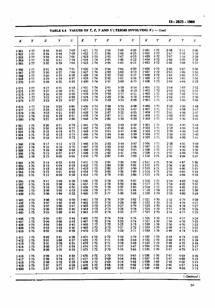
I
IS:2%25-1969
TABLE 4.4 VALUES OF T, Z, Y AND U ( TERMS INVOLVING K) - Confd
x 7 Z Y u
1.361 1.77 1.362 1.77 1.363 1.77 1.364 1.77 1.365 1.77
::E 1.77 1.77 l-3@ ,1*77
f % 1.77 1.77
1.371 lt77 1.372 1.77 1.373 1.77 1.334 1.77 1.375 1.77
I.376 1.77 1.377 1.77 1.378 1.76 1.379 1.76 1.380 1.76
1.381 1.76 1.382 1.76 1.383 1.76 1.384 1.76 1.385 1.76
1.386 1.76 1.387 1.76 1.388 1.76 1.389 1.76 1.390 1.76
l-391 1.76 1.392 1.76 l-393 1.76 1.394 l-76 1.395 1.76
1.396 l-76 1.397 1.76 1.398 1.75 l-399 1.75 1400 l-75
1401 1.75 1402 1.75 l-403 1.75 1.404 1.75 1405 1.75
1.406 1-75 1.407 1.75 1408 1.75
E 1.75 1.75
1.411 1*75 l-412 1.75 1.413 1.75 1.414 1.75 1.415 1.75
;a; y:
1.418 1.75 l-419 l-75 l-420 l-75
3.35 334 3-33 3-32 3-32
3.31 330 330 3-29 3.28
3.27 3.27 3.26
;::i:
3.24 3.23 3.22 3.22 3.21
E 3.19 3.18 3.18
3.17 3-16 3.16 3.15 3-15
3-05
::Ez 303 3.02
6-45
:z 6.41 639
6.38 637 6-35 6.34 632
6.31 6-30 6.28 6.27 6.25
6.24 6.22 621 6.19 6.18
6-15 6.16 6.14 6.13 612
6.11 6.10 6-08 6.07 6.06
605 6.04 602 6.01 6-00
5-99 5-98 5.96 5-95 5.94
5.87 586 5.84 583 582
581 5-80 5-78 5-77 576
5.75 5-74 5.72
5E
7.09 7.08 7.06 7.04 7.03
7.01 7.00 6.98 6.97 S.95
6.93 6.91 6.90 6.89 6.87
6.86 6.84 6.82 6.81 6.80
6.79 6.77 6-75 674 6.73
6.72 6.70 6.68 6.67 6.66
664 663 6.61 6.60 659
6.58 656 635 6.53 6.52
6.50 6-49 6.47 6.46 6.45
f:G 6.41 640 6.39
638 637 6.35 6.34 6.33
6-32 6.31 629 6-28 6.27
K T Z Y u
1.421 1.75 1.422 1.75 lr423 1.75 1.424 1.74 l-425 1.74
1.426 l-74 1.427 l-74 1.428 1.74 1.429 1.74 1.430 1.74
1,431 1.74 1.432 l-74 1.433 1.74 1.434 1.74 1.435 1.74
1.436 1.74 1.437 1.74 ;*:a; ;‘;:
1440 1,74
1.441 1.74 1.442 l-74 1443 1.74 1444 1.74 1.445 1.74
1446 1.74 1447 1.73 1448 l-73 1449 1.73 1.450 1.73
1.451 l-73 1.452 l-73 1.453 1.73 1.454 1.73 l-455 1.73
f’;;; y;
1.458 l-73 1.459 l-73 1.460 l-73
1.461 1.73 1462 1.73 t-g; f’;:
1465 1.73
t:z :::: 1.468 1.72 1.469 1.72 1.470 1.72
l-471 1.72 l-472 l-72 1.473 1.72 1.474 1.72 l-475 1.72
1.476 1.72 i.477 1.72 1.478 l-72 1.479 1.72 1480 1.72
2.96 5.69 &26 2.96 5.68 625 2.95 5.67 6-23 2.95 5.66 6.22 2.94 5.65 621
1.481 1.72 2.68 5.11 5.60 1.482 1.7% 2.67 5.10 5.59 1-483 1.72 2.67 5.10 5.59 1.484 1.72 2.66 5.09 5.58 l-485 1.72 2.66 5.08 5.57
;:iz 2.92 2.92 2.91
5.64
;“7;
5.60
6-20 6.19 6.17 6.16 6.15
1486 1.72 2.66 5.07 5.56 1487 1.72 2.65 5.06 5.55 1.488 1.72 2.65 5.06 5.55 1489 1.72 2.64 5.05 5.54 1.490 l-72 2.64 5.04 5.53
2.91 5.59 6.14 2.90 5.58 6.13 2.90 5.57 6.11 2.89 5.56 6.10 2.89 5.55 6.09
1.491 1.72 2.64 5.03 5.52 1.492 1.72 2.63 5.02 5.51 1.493 1.71 2.63 5a 5.51 1.494 1.71 2.62 5.01 5.50 1.495 1.71 2~62 5w 5.49
2.88 5.54 6.08 2.88 5.53 6.07 2.87 552 6.05 2.87 5.51 6-04 2.86 5.50 6.03
1.496 1.71 2.62 4.99 5.48 1.497 1.71 2.61 4.98 5.47 1.498 1.71 2.61 4.98 5.47 1.499 1.71 2.60 4.97 5.46 1.500 1.71 2.60 4.96 5.45
2.86 5.49 6.02 1.501 1.71 2.60 4.95 5.44 2.85 5.48 6.01 1.502 1.71 2.59 494 5.43 2.85 5.47 6.00 1.503 1.71 2.59 4.94 5.43 2.84 5.46 5.99 1.504 1.71 2.58 4.93 5.42 2.84 5.45 5.98 1.505 1.71 2.58 4.92 5.41
2.83 2.83 2.82 2.82 2.81
%z 5.42 541 5.40
5.97 1.506 1.71 2.58 4.91 5.40 5.96 l-507 1.71 2.57 4.90 5.39 5.95 1.508 1.71 2.57 490 5.39 594 1.509 1.71 2.57 4.89 5.38 5.93 1.510 1.71 2.56 488 5.37
2.81 5.39 2.80 538 2.80 5-37 2.80 5.36 2.79 5.35
5-92 5.91
z:g 588
i.511 1.71 2.56 487 5.36 1.512 1.71 2.56 486 5.35 l-513 1.71 2.55 4.86 5.35 1.514 1.71 2.55 485 5.34 1.515 1.71 2.54 4.84 5.33
2.79 2.78 2.78 2.77 2.77
Z:E 532 5-31 5.30
5.87 1.516 1.71 2.54 4.83 5.32 5.86 1.517 l-71 2.54 4.82 5.31 585 1.518 1.71 2.53 4.82 5.31 $84 1.519 1.70 2.53 4.81 5.30 5-83 1.520 1.70 2.53 480 5.29
2.76 5.29 5.82 1.521 1.70 2.52 4.79 5.28 2.76 5.28 5.80 1.522 1.70 2.52 479 5.27 2.75 5.27 5.79 1.523 1.70 2.52 4.78 5.27 2.75 5.26 5.78 1.524 1.70 2.51 478 5.26 2.74 5.25 5-77 1.525 1.70 2.51 477 5.25
2.74 5.24 576 1.526 1.70 2.51 477 5.24 2.74 5-23 5.74 1.527 1.70 2.50 4.76 5.23 2-73 5.22 5.73 1.528 1.70 2.50 476 5.23 2.73 5.21 5.72 1.529 1.70 2.49 4.75 5.22 2.72 5.20 5.71 1.530 1.70 2.49 4.74 5.21
2.72 5-19 5.70 1.531 1.70 2.49 473 5.20 2.71 518 969 1.532 l-70 2.48 472 5-19 2.71 5.18 5.68 1.533 1.70 248 4.72 5.19 2.71 5.17 567 1.534 1.70 2.48 4-71 517 2.70 5-16 5.66 1.535 1.70 2.47 4-70 5-17
2.70 915 2.69 914 269 5-14 2.68 213 2.68 5.12
565
::: 5-62 5-61
1.536 l-70 l-537 1.70 1.538 1.69 1.539 1.69 l-540 1.69
2.47 2.47 2.46
z
469 5.16 468 5.15 4-68 5.15 467 5.14 4.66 5.13
K l- 2 Y u
( Confind )
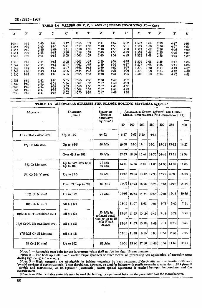
IS : 2825 - 1969
TABLE 4.4 VALUES OF T, Z, I’ AND U (TERMS INVOLVING K) _ anid
K T Z Y (I K I Z Y u R 9 z Y u
1.541 1.542 1.543 1.544 1.545
1.546 1.547 1.548 I.549 1.550
1.551 1.552 1.553 1.554 1.555
1.69 2.45 169 2.45 1.69 2.45 1.69 2.45 1.69 244
1.69 2.44 1.69 244 1.69 2.43 1.69 2.43 1.69 2.43
1.69 2.42 1.69 242 1.69 2.42 1.69 2.41 1.69 2.41
2::: 464 464 4.63
512 511 5.11 5.10 5.09
463 5.08 462 507 4.62 507 461 5.06 460 505
460 459
:::: 457
505 584 503 5.03 5.02
ym& y; 2.41
l.558 1:69 z 1.559 1.69 1.560 1.69 ;:;
1.561 1.69 2.39 1.562 1.69 2.39 ;‘;%i ;‘;tx$ 2.38 2.39
1.565 1.68 2.38
i-z%; ;*6$ 2.38 2.37 1.568 1.68 2.37 1.569 1.68 2.37 1.570 1.68 2.37
457
::z 455 454
5.02 501 5.00 499. 499
454 498 4.53 497 452 497 4.51 4.96 451 495
450 495 450 494 449 493 448 492 448 492
1.571 1.68 2.36 447 491 1.572 1.68 2’36 447 491 1.573 1.68 2.36 446 490 1.574 1.68 2.35 446 489 1.575 1.68 235 445 489
1.576 1.68 2.35 1.577 1.68 2.35 $2 ::z 1.578 1.68 2.34 443 487 1.579 1.68 2.34 442 486 1.580 1.68 2.34 442 486
TABLE 4.5 ALLOWABLE STRESSES FOR FLANGE BOLTING MATERIAL kgf/ansy$ -
I .
__--
MATERIAL DIAMETER S~GCIFIED ALLOWABLE STRESS kgf/mm* FOR DESIGN (mm) TENSILE METAL TEMPERATURE NOT EXCEEDING ( OC )
Hot rolled carbon steel up to 150 ( 44-52 1 5.87 1 5.62 15.45 ( 485
1:/o Cr MO steel Up to 63.5 86 Min 1968 18.5 17.1 162
_---
Over 63’5 to 102 79 Min 17.79 16.66 15.47 1476
5% Cr MO steel Up to 63.5 over 63.5 up to 102
I
71 Min 66 Min 11406/ 1406) 14.061 14.06
1% Cr Mo V steel 1 Up to 63.5 I 86 Min 1 1968 1 1905 1 1849 j 17.9?
1 Over 63.5 up to 102 1 82 Min 1 17.79 1 17.23 1 1666 1 1624
13% Cr Ni steel I
up to 102 I
71 Min 117.93~1645(1434~13*64
18/8 Cr Ni steel I All (1) (2) I
1 13.181 11.07 1 865 1 8.01
1818 Cr Ni Ti stabilized steel All (1) (2) 55Miain
softened condi- 13.18 11.53 1819 9.4s
tionorupto88 --- --
18/9 Cr Ni Nb stabilized ateel All (1) (2) Min if cold drawn 13.18 11.53 1819 9.4s
17/10/2f Cr Ni MO steel All (1) (2) I
j 1318) ll*IsI 9.561 88ti
18 Cr 2 Ni steel I up to 102 I 86Min 121.581 19801 17.301 16.4f
300 350 408
---
- - -
---
15.541 14.69j 12.94 )
NOTE1 - Austenitic steel bolts for use in pressure joints shall not be less than 10 mm diameter. Nuns2 - For bolts up to 38 mm diameter torque spanners or other means of preventing the application of excessive stress
during tightening are necessary. NATE 3 - High strengths are obtainable in bolting materials by heat treatment of the ferritic and martensitic steels and
by cold working of amtenitic steels. These should not, however, be usedfor bolting with tensile strengths greater than 110 kgf/mm* fm~~~a;mr~ martensitic ) or 100 kgf/ mm* ( austenitic ) unless special agreement is reached between the purchaser and the
Nom 4 ’ - Other suitable materials may be used for bolting by agreement between the purchaser and the manufacturer.
60
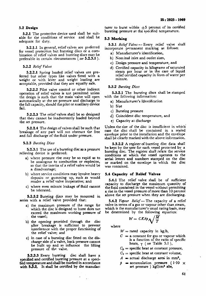
IS I 2825 - 1969
turer to burst within &5 percent of its certified bursting pressure at the specified temperature.
5.3 Marking
5.3.1 Relief Valves - Every relief valve shall incorporate permanent marking as follows:
a) Manufacturer’s identification, b) Nominal inlet and outlet sizes, c) Design pressure and temperature, and d) Certified capacity in kilograms of saturated
steam per hour or in the case of liquid relief certified capacity in litres of water per minute.
5.2 Design
5.2.1 The protective device used shall be suit- able for the conditions of service and shall be adequate for duty.
5.2.1.1 In general, relief valves are preferred for vessel protection but bursting discs or a com- bination of relief valves and bursting discs may be preferable in certain circumstances ( see 5.2.3.1 ).
5.2.2 Relief Valves
5.2.2.1.,Spring loaded relief valves are pre- ferred but other types like valves fitted with a weight or with lever and weight loading are acceptable, provided that they are equally safe.
5.2.2.2 Pilot valve control or other indirect operation of relief valves is not permitted unless the design is such that the main valve will open automatically at the set pressure and discharge to the full capacity, should the pilot or auxiliary device fail.
5.2.2.3 The relief valves shall be so designed that they cannot be inadvertently loaded beyond the set pressure.
5.2.2.4 The design of valves shall be such that breakage of any part will not obstruct the free and full discharge of the fluid under pressure.
5.2.3 Bursting Discs
5.213.1 The use of a bursting disc as a pressure relieving device is preferred:
a) where pressure rise may be so rapid as to be analogous to combustion or explosion, so that the inertia of a relief valve would be a disadvantage;
b) where service conditions may involve heavy deposits or gumming up, such as would render a re!ief valve inoperative; and
c) where even minute leakage of fluid cannot be tolerated.
5.2.3.2 Bursting discs mav be mounted in series
a)
with a relief “valve provided that: the maximum pressure of the range for which the disc is designed to burst does not exceed the maximum working pressure of the vessel;
b)
c)
the opening provided through the disc after breakage is sufficient to prevent interference with the proper functioning of the relief valve; and in case of a bursting disc fitted on the dis- charge side of a valve, back pressure cannot be built up and so influence the lifting pressure of the valve.
5.233 Every bursting disc shall have a specified and certified bursting pressure at a speci- fied tem erature and shall be marked in accordance with 5 B .2. It shall be certified by the man&c:
5.3.2 Bursting Discs
5.3.2.1 The bursting discs shall be stamped with the following information:
4 Manufacturer’s identification
b) Size
cl Bursting pressure
4 Coincident disc temperature, and
e) Capacity at discharge
Unless the size of the disc is insufficient in which case the disc shall be contained in a sealed envelope prior to the installation and the envelope shall be clearly marked with the above information.
5.3.2.2 A register of bursting disc data shal1 he kept by the ‘user for each vessel protected by a bursting disc. The register shall relate the service conditions at which the vessel operates to the serial letters and numbers stamped on the disc or marked on the envelope in which the disc was contained.
5.4 Capacity of Relief Valves
5.4.1 The relief valve shall be of sufficient capacity to discharge the maximum quantity of the fluid contained in the vessel without permitting a rise in the vessel pressure of more than 10 percent above the set pressure when they are discharging.
5.4.2 Vapour Relief-The capacity of a relief valve in terms of a gas or vapour other than steam, which is the manufacturer’s usual rating basis, may be determined by the following equatian:
W- CKAp $(
where W = rated capacity in kg/h, c = a constant for gas or vapour which
is a function of the ratio of specific heats, y ( see Table 5.1 ),
CP = specific heat at constant pressure, C, = specific heat at constant volume, A I= actual discharge arti in nuns, fi = accumulation pressure ( l-10 x
set pressure ) kgf/cm* abs,
61
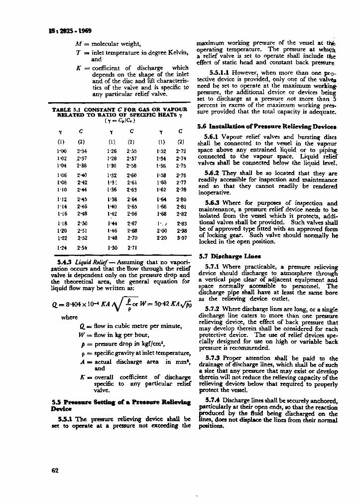
112825-1969
hf = molecular weight,
I r= inlet temperature in degree Kelvin, and
K = coefficient of discharge which depends on the shape of the inlet and of the disc and lift characteris- tics of the valve and is specific to any particular relief valve.
TABLE 5.1 CONSTANT C FOR GAS OR VAFOUR RELATED TO RATIO OF SPECIFIC HEATS Y
Y c
(1) (2)
190 2’34
1.02 2.37
l-04 2-38
l-06 2.40
l-08 2.42
l-10 2.44
1.12 2’45
l-14 2-46
l-16 2.48
1.18 2.50
l-20 2’51
1.22 2.52
l-24 2-54
Y c
(1) (2)
1.26 2.55
1.28 2.57
l-30 2.58
1.32 2.60
1.3: 2.61
I.36 2.63
1.38 2.64
1.40 2-65
l-42 2.66
I.44 2.67
1.46 2.68
1.48 2’70
l-50 2.71
Y C
(1) (2) 1.52 2.72
l-54 2.74
1% 2.75
1.58 2.76
l-60 2.77
1.62 2’78
l-64 2-80
I.66 2.81
l-68 2.82
I-. J 2.83
2.00 298
2.20 3.07
5.43 Liquid Relkf - Assuming that no vapori- zation occurs and that the ‘flow through the relief valve is dependent only on the pressure drcip and the theoretical area, the general equation for liquid flow may be written as:
Q=8N4xlO-‘KA ;orW=50.42KAfiP 2/-
where Q = flow in cubic metre per minute,
W x flow in kg per hour,
p = pressure drop in kgf/cms,
P = ape&c gravity at inlet temperature,
A = actual discharge area in mm*, and
K = overall coefficient of discharge specific to any particular relief valve.
5~PreMsresetdngofaPresmureRelitving Device
55.1 The pressure relieving device shall be set to operate at a pressure not exceeding t.l~e
62
maximum working pressure of the vessel at t& operating temperature. The pressure at whr<h a relief valve is set to operate shall include the effect of static head and constant back pressure
5.5.1.1 However, when more than one prao- tective device is provided, only one of the valvafl need bc set. to operate at the maximum workin& pressure, the additional device or devices being set to discharge at a pressure not more than 5 percent in excess of the maximum working pres- sure provided that the total capacity is adequate.
5.6 Installation of Pressure Relieving Devicea
5.6.1 Vapour relief valves and bursting discs shall be connected to the vessel in the vapour space above any entrained liquid or to piping connected to the vapour space. Liquid relief valves shall be connected below the liquid level.
5.6.2 They shall be so located that they are readily accessible for inspection and maintenance and so that they cannot readily be rendered inoperative.
5.63 Where for purposes of inspection and maintenance, a pressure relief device needs to be isolated from the vessel which it protects, addi- tional valves shall be provided. Such valves shall be of approved type fitted with an approved form of locking gear. Such valve should normally be locked in the open position.
5.7 Discharge Lines
5.7.1 Where practicable, a pressure relieving device should discharge to atmosphere through a vertical pipe clear of adjacent equipment and space normally accessible to personnel. The discharge pipe shall have at least the same bore as the relieving device outlet.
5.7.2 Where discharge lines are long, or a single discharge line caters to more than one pressure relieving device, the effect of back pressure that may develop therein shall be cbnsidered for each protective device. The use of relief devices spe- cially designed for use on high or variable back pressure is recommended.
5.7.3 Proper attention shall be paid to the drainage of discharge lines, which shall be of such a size that any’ pressure that may exist or develop therein will not reduce the relieving captiity of the relieving devices below that required to properly protect the vessel.
5.7.4 Discharge lines shall be securely anchored, particularly at their open ends, so that the reaction
En ’ ductA by the fluid being discharged on the
CS, docJ not displace the lines from their nod p3itiOIlS.
SECTION II FABRICATION ANb WELDING
6. MANUFACTURE AND WORKMANSHIP
6.1 Approval of Design
6.2 Welded Joints, General Considerations
6.3 Design of Welded Joints
6.4 Preparation of Parent Metal
6.5 Assembly of Plates ntid Fit-Up
6.6 Alignment and Tolerances
6.7 Welding Procedure
6.8 Welding of Non-ferrous Metals
6.9 Rectification of Welds
6.10 Repair of Drilled Holes
6.11 Repair of Cracks
6.12 Post Weld Heat Treatment
7. WELDINO QUALIFICATIONS
7.1 Welding Procedure Qualifications
7.2 Welder’s Performance Qualifications
. . . 65
. . . 65
. . 65
. . . 65
. . . 67
. . . 71
. . 71
. . . 72
. . 74
. . . 74
. . . 75
*.. 75
. . . 75
. . . 79
. . . 79
.*. 85
6. MANUFACTURE AND WORKMANSHIP
6.1 Approval of Design - Refore commencing manufacture, the manufacturer, if so required, shall submit for approval by the purchaser a fully dimensioned drawing showing the pressure portions of the vessel and carrying the following information:
4
b)
C!
4
4
f) g)
h)
A statement that the vessel is to he con- structed to this standard.
Specification(s) to which materials shall conform.
Welding process(es) to be adopted for all parts of the vessel.
Large-scale dimensional details of the weld preparation for the longitudinal and circumferential seams and details of the joints for branch pipes, seatings, etc, and the position of these joints relative to the longitudinal and circumferential seams and other openings.
Design pressure(s) and temperature(s) and major structural loadings.
Test ,pressure(s) .
Amount and location of corrosion allowance.
No modification shall be made to the approved design except with prior agree- ment between the purchaser and the manu- facturer.
Additional requirements, if any, specified by the purchaser.
i.2 Welded Joints, General Considerations
6.2.1 Welded construction of pressure vessels 1s subjected to the following general conditions.
6.2.1.1 All details of design and construction shall generally conform to the provisions of this code. ( Examples of typical designs of welded connections are given in Appendix G. )
6.2.1.2 The materials shall conform to the requirements of the appropriate Indian Standards or shall be any other approved material.
6.2.1.3 The welders shall be qualified for the type of welding concerned in conformity with the welder’s performance qualification ( see 7.2 ).
6.2.2 Nozzles, pads; branches, pipes, tubes, etc, and non-pressure parts may be welded to pressure parts provided that the strength and the character- istics of the material of the pressure parts are not affected adversely.
If heat treatment is mandatory under the requirements of this code, the attachment of parts mentioned above by welding shall take place before the final heat treatment.
6.2.3 The manufacturer of a pressure vessel built according to this code, shall be responsible for all the welding work done under this code.
IS : 2825 - 1969
The manufacturer shall conduct the tests required in this code ( see 7.1 anJ 7.2 ) to qualify the welding procedure employed and to judge performance of the welders who apply this procedure.
6.2.4 The manufacturer shall maintain a record of the results obtained in welding procedure quali- location tests ( see Appendix H ).
These records giving an acctuate description of all the particulars of the materials and procedure concerned shall be certified by him and shall be accessible to the inspecting authority who should be permitted to witness the tests if he so desires.
6.2.5 Any person who wishes to qualify for a welder’s performance test under this code shall not be below the age of 18 years and shall have been employed as a welder in a workshop or firm for a period of not less than two years.
A record shall be kept to show that the welder has been employed on work of the kind covered by his performance tests, during the previous six months.
These records shall contain the results of the welder’s performance tests and the identification mark assigned to each welder. T!rey shall be certified by the manufacturer and be accessible to the inspecting authority ( see Appendix H ).
The welds made by each welder shall he marked with a stamp showing the welder’s identity at intervals of one metre or less, Care shall be taken to avoid notching or stress concentration due to deep stamping of welder’s identity. Deep stamp- ing as a means of identifying welded seam is not recommended on carbon steel plates less than 7 mm thick or vessels subject to low temperatures or on austenitic and alloy steels. When deep stamping is not permitted, a record shall be kept by the manufacturers of welders and welding operators employed on each joint which shall be available to the inspecting authority; suitable stencil or other surface markings may be used additionally.
6.2.6 The inspecting authority shall have the right to disqualify a welder any time during the fabrication of a vessel, when there is a specific
reason to question his ahility to make welds that meet this code requirements. Such a disquali- fied welder at the option of the manufacturer may be put up for retests, under the conditions specified in 7.2.8.1.
6.3 Design of Welded Joints
6.3.1 Single fillet welded lap joints should not be used without previous consent of the inspecting authority.
6.3.2 In the design of all details the aim shall be to avoid disturbances in the flow of the lines of force, in particular in constructions subjected to fatigue stresses. Holes and openings shall not be positioned on or. in the heat affected zones of
65
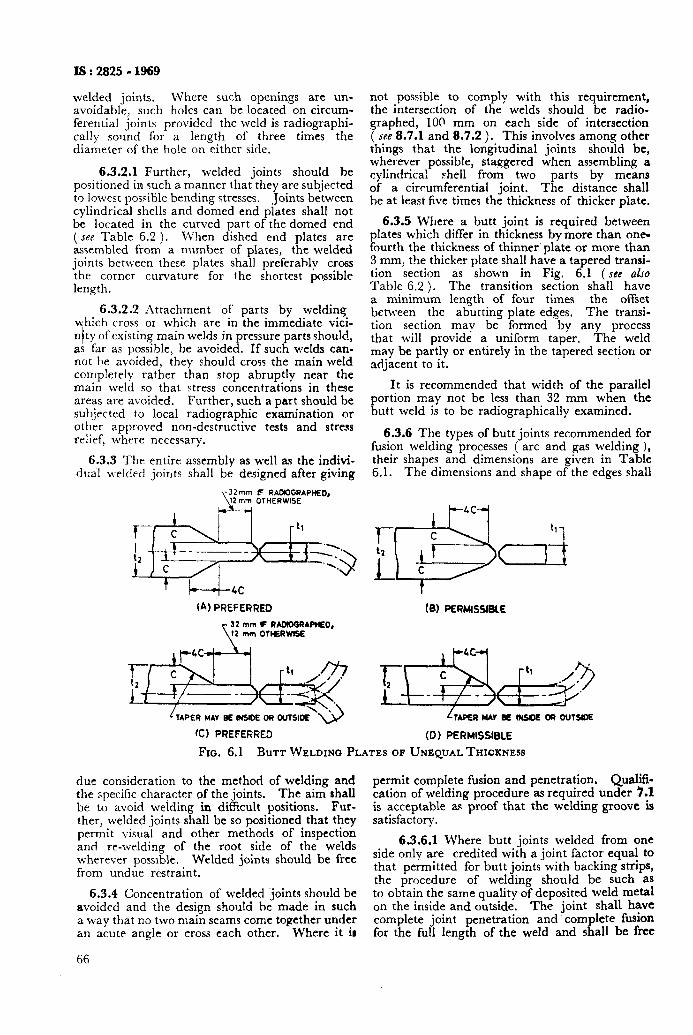
IS:2825 - 1969
welded joints. Where such openings are un- avoidable? such holes can be located on circum- ferential Joints provided the weld is radiographi- tally solmd for a length of three times the diameter of the hole on either side.
6.3.2.1 Further, welded joints should be positioned in such a manner that they are subjected to lowest possible bending stresses. *Joints between cylindrical shells and domed end plates shall not be located in the curved part of the domed end ( gee Table 6.2 ). When dished end plates are assembled from a number of plates, the welded joints bettveen these plates shall preferahly cross the corner curvature for the shortest possible length.
6.3.2.2 Attachment of’ parts by welding which cross or which are in the immediate vici- nity of existing main welds in pressure parts should, as far as possible, be avoided. If such welds can- not he avoided, they should cross the main weld completely rather than stop abruptly near the main weld so that stress concentrations in these areas are avoided. Further, such a part should be subjected to local radiographic examination or other approved non-destructive tests and stress relief, where necessary.
6.3.3 The entire assembly as well as the indivi- dua’l welded joints shall be designed after giving
T I---+--4c (A) PREFERRED
L TAPER MN BE INSlOE OR OUTSILX “u
CC) PREFERRED
not possible to comply with this requirement, the intersection of the welds should be radio- graphed, 100 mm on each side of intersection ( SM 8.7.1 and 8.7.2 ). This involves among other things that the longitudinal joints should be, wherever possible, staggered when assembling a cylindrical shell from two parts by means of a circumferential joint. The distance shall he at least five times the thickness of thicker plate.
6.3.5 Where a butt joint is required between plates which differ in thickness by more than one- fourth the thickness of thinner plate or more than 3 mm, the thicker plate shall have a tapered transi- tion section as shown in Fig. 6.1 ( see also
Table 6.2 ). The transition section shall have a minimum length of four times the offset between the abutting plate edges, The transi- tion section may be fnrmcd by any process that will provide a uniform taper. The weld may be partly or entirely in the tapered section or adjacent to it.
It is recommended that width of the parallel portion may not be less than 32 mm when the butt weld is to be radiographically examined.
6.3.6 The types of butt joints recommended for fusion welding processes ( arc and gas welding 1, their shapes and dimensions are given in Table 6.1. The dimensions and shape of the edges shall
4C
P c t2 6 1 t1
i f--- cd
LTAPER MAr BE IWM OR oulsloE
(0) PERMISSIBLE
Fro. 6.1 BUTT WELDING PLATES OF UNEQUAL THICKNESS
due consideration to the method of welding and the specific character of the joints. The aim shall be to avoid welding in dificult positions. Fur- ther, welded joints shall be so positioned that they permit visual and other methods of inspection and re-welding of the root side of the welds wherever posslblb. Welded joints should be free from undue restraint.
6.3.4 Concentration of welded joints should be avoided and the design should he made in such a way that no two main seams come together under an acute angle or cross each other. Where it ir
permit complete fusion and penetration. Qualifi- cation of welding procedure as required under 7.1 is acceptable aq proof that the welding groove is satisfactory.
6.3.6.1 Where butt joints welded from one side only are credited with a joint factor equal to that permitted for butt joints with backing strips, the procedure of welding should be such as to obtain the same quality of deposited weld metal on the inside and outside. The joint shall have complete joint penetration and complete fusion for the full length of the weld and shall be free
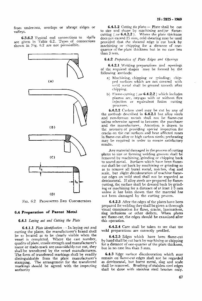
IS : 2825 - 1969
from undercuts, overlaps or abrupt ridges or valleys.
6.3.6.2 Typical end connections to shells are given in Tabie 6.2.. Types of connections shown in Fig. 6.2 are not permissible.
(A)
(B)
(0)
FIG. 6.2 PROHIBITED END CONNECTIONS
6.4 Preparation of Parent Metal
6.4.1 Lulling out and Cutting the Plate
6.4.1.1 Plate identification - In laying out and cutting the plates, the manufacturer’s brand shall be so located as to be clearly visible when the vessel is completed. Where the cast number: quality of plate, tensile strength and manufacturer’s name or trade-mark are unavoidably cut out, they shall be transferred by the vessel manufacturers. The form of transferred markings shall be readily distinguishable from the plate manufacturer’s stamping. The arrangement for the transferred markings should be agreed with the inspecting authority
6.4.1.2 Cutting the plates - Plate shall be cut to size and shape by machining and/or flame- cutting ( see 6.4.2.2 ). Where the plate thickness does not exceed 25 mm, cold shearing may be used provided that the sheared edge is cut back by machining or chipping for a distance of one- quarter of the plate thickness but in no case less than 3 mm.
6.4.2 Preparation of Plate Edges and Openings
6.4.2.1 Welding preparations and openings of the required shapes may be formed by the following methods:
a) Machining, chipping or grinding; chip- ped rurfaces which are not covered with weld metal shall be ground smooth after chipping.
b) Flame-cutting ( see 6.4.2.2 ) which includes plasma arc, oxy-gas with or without flux injection or equivalent fusion cutting processes.
6.4.2.2 Carbon steel may be cut by any of the methods described in 6.4.2.1 but alloy steels and non-ferrous metals shall not be flame-cut unless otherwise agreed to between the purchaser and the manufacturer. Attention is drawn to the necessity of providing special inspection for cracks on the cut surfaces and heat affected zones in flame-cut alloy or high carbon steels; preheating may be required in order to ensure satisfactory results.
Any material damaged in the process of cutting plates to size or forming welding grooves shall be removed by machining, ‘grinding or chipping back to sound metal. Surfaces which have been flame- cut shall be cut back by machining or grinding so as to remove all burnt metal, notches, slag and scale, but slight discolouration of machine flame- cut edges on mild steel shall not be regarded as detrimental. If alloy steels are prepared by flame- cutting, the surface shall be dressed back by grind- ing or machining for a distance of at least I.5 mm unless it has been shown that the material has not been damaged by the cutting process.
6.4.2.3 After the edges of the plates have been prepared for welding they shall be given a thorough visual examination for flaws, cracks, laminations, slag inclusions or other defects. When plates are flame-cut, the edges should be examined after this operation.
6.4.2.4 Care shall be taken to see that the weld preparations are correctly profiled.
6.4.2.5 Edges which have been flame-cut by hand shall be cut back by machining or chipping for a distance of one-quarter of the plate thickness, but in no case less than 3 mm.
6.4.3 Edge surface discolouration which may remain on' flame-cut edges shall not be reggrded as detrimental, but burnt metal, slag and scale shall be removed. Brushing of stainless steel edges shall be done with stainless steel brushes only.
67
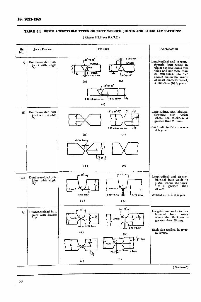
IS t !2s!&1969
TABLE 6.1 SOME ACCEPTABLE TYPES OF BLTT WELDED JOINTS AND THEIR LIMITATIONS+
( Claures 6.3.6 and 8.7.3.2 )
If:. --
i]
ii)
_
iii)
iv:
JOINT DETAIL
>oubIe-welded butt join t with single *V’
)oublc-welded butt joint with double ‘V’
-
I I
--
, I
--
1
--
) 1
)oublc-welded butt joint with single ‘U’
3oubIe-welded butt joint with double ‘U’
FIGURES APPLICATION
(a) (b)
Lii$?a. (C)
4810 do ,$
(a) (b)
(0) (d)
sm MN’ 010 1.5mm-lC Ls TO SJnm
(a) (b)
(b)
20’ w 4 *mm ts 7mmR
--IId V)mm arm
(d)
.ongitudinal and circum- ferential butt welds in plates not less than 5 mm thick and not more than 20 mm thick. The ‘V’ should be on the inside of small diameter vessel, a shown in (b) opposite.
Angitudinal and circum- ferential butt welds where the thickness is greater than 20 mm.
!ach side welded in rever- al layers.
,ongitudinal and circum- fercntial butt welds in plates where the thick- nrss is greater than 20 mm.
Melded in several layers.
Longitudinal and circum- ferential butt welds where the thickness is greater than 20 mm.
Each side welded in sever- al layers.
( Confind )
68
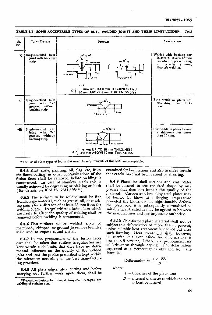
IS : 2825 - 1969
TABLE 6.1 SOME ACCEPTABLE TYPBS OF BUTT WELDED JOINTS AND THEIR LIMITATIONS* - Conrd
2.
4
4
Vii)
JOINT DETAIL
Single-welded butt joint with backing strip
Single-welded butt joint with ‘V’
groove, without backing strip
Single-welded .butt joint with ‘V’
without GGZg strip
-
. -
de
-I-
!
$0) (b)
8 mm UP TO 8 mm THiCKNESS ( ts ) mm ABOVE 8 mm THICKNESS ( fs I
A 1.5 mm UP TO IO mm THICKNESS 3.0 mm ABOVE IO mm THICKNESS
APPLICATION
Welded with backing bar in several layers. Device essential to prevent slag or powder running through welding.
Butt welds in plates not exceeding 10 mm thick- ness.
Butt welds in plates having a thickness not more than 16 mm.
*‘the use of other types of joints that meet the requirements of this code are acceptable.
6.4.4 Rust, scale, painting, oil, slag, etc, from the flame-cutting or other contaminations of the fusion faces shall be removed before welding is commenced. In case of stainless steels this is usually achieved by degreasing or pickling or both ( for details, see 8 of IS : 281 l-1964* ).
6.4.5 The surfaces to be welded shall be free from foreign material, such as grease, oil, or mark- ing paints for a distance of at least 25 mm from the welding edges. Irregularities in fusion faces which are likely to affect the quality of welding shall be removed before welding is commenced.
6.4.6 Cast surfaces to be welded shall be machined, chipped or ground to remove foundry scale and to expose sound metal.
6.4.7 In the preparation of the fusion faces care shall be taken that surface irregularities are kept within such limits that they have no detri- mental influence on the quality of the welded joint and that the profile prescribed is kept within the tolerances according to the best manufactur- ing practices.
6.4.8 All plate edges, after cutting and before ‘carrying out further work upon them, shall be
*Recommendations for manual tungsten inert-pas arc- w&ling of stainless ateel.
examined for laminations and also to make certain that cracks have not been caused by shearing.
6.4.9 Plates for shell sections and end plates shall be formed to the required shape by any process that does not impair the quality of the material. Carbon and low alloy steel plates may be formed by blows at a forging temperature provided the blows do not objectionably deform the plate and it is subsequently normalized or suitably heat-treated as may be agreed to between the manufacturer and the inspecting authority.
6.4.10 Cold-formed plate material shall not be subject to a deformation of more than 5 percent, unless suitable heat treatment is carried out after such forming. Heat treatment shall, however, be carried out even when the deformation is less than 5 percent, if there is a pronounced risk of brittleness through ageing. The deformation expressed as a percentage is obtained from the formula:
tx 100 Deformation = T
where
t=
D-
thickness of the plate, and
internal diameter to which the piate is bent or formed.
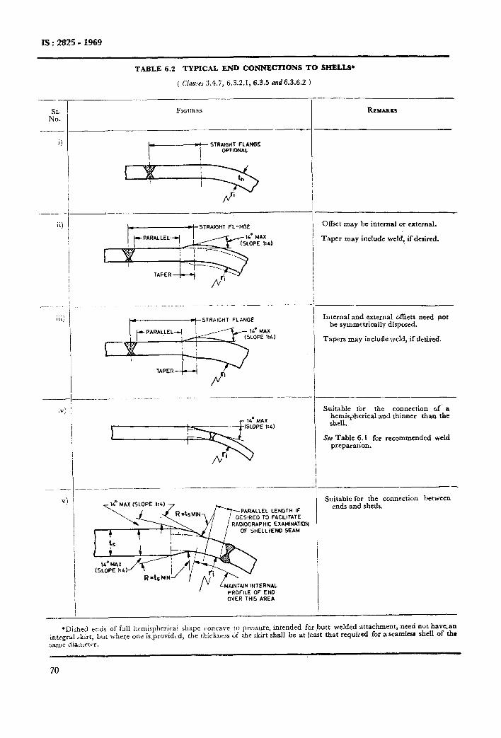
IS : 2825 - 1969
TABLE 6.2 TYPICAL END CONNECTIONS TO SIiBLLS*
( Uauw 3.4.7, 6.3.2.1, 6.3.5 und6.3.6.2 )
--
SL No.
ii)
_.._
iii)
FIGURES
) i
L-STRAIGHT FL -NGi
t z; STRAIGHT FLANGE
PARALLEL LENGTH IF DESIRED T3 FACILITATE ADlOGRAPHlC EXAMINATION
OF SHELL/END SEAM
&tA,NTAlN INTERNAL PROFILE OF END OVER THIS AREA
--
_-
--
t I
_:_
_-
--
l
--
RBMAX~KS
Offset may be internal or external.
Taper may include weld, if desired.
Internal and external offsets need not be symmetrically disposed.
Tapers may include weld, if dellred.
Suitable ior the connection of. a hemispherical and thinner than the shell.
See Table 6.1 for recommended weld preparation.
Suitable for the connection between ends and shells.
*Dished ends of fall hemispherical shape concave 10 pressure, intended forbutt welded attachment, need not have.an integral G&r, but where one kprovidcd, the thlckncss if the skirt shall be at least that required for a seamlev shell of thr same Amietrr.
70
Is:282501968
welding. Domed ends which are inserted in the shell shall be a good fit.
6.5.6 The edges of butt joints shall be properly aligned so that the tolerances given in 6.6 are not exceeded in the completed joint. Where fitted girth joints have deviations exceeding the permis- sible tolerances, the head or shell ring whichever is not true shall be re-formed until the errors are within the limits specified.
Cold-forming shall not .be undertaken when the temperature of the metal is less than 0°C. If the forming or bending operation takes place in hot condition, no subsequent heat treatment is required, if the final shaping process terminates within the correct temperature limits for the particular material.
6.4.11 Plates Welded Prior to Forming - Seams in plates may be welded prior to forming provided they meet the specified mechanical test require- ments and that they are examined radiographically throughout the entire length after forming. After forming, the surfaces of such seams; in alloy steel parts, also in carbon steel parts over 25 mm in thickness, shall be ground smooth and inspected for cracks by ‘magnetic crack detection, dye pene- trants or other agreed means.
6.4.12 Cold-rolling of a welded shell to rectify a small departure from circularity is permitted, subject to the concurrence of the inspecting authority provided that the radiography ( see 8.7 ) takes place after such cold-rolling, where radio- graphy is called for.
6.4.13 Butt Welds Between Plates of Unequal Thickness- Where two plates at a welded joint differ in thickness by more than 3 mm the thicker plate shall be trimmed to a smooth taper as stipulated in 6.3.5.
6.5 Assembly of Plates and Fit-Up
6.5.1 Bars, jacks, clamps, tack welds or other appropriate means may be used to hold the edges to be welded in line. All tack welding shall be properly carried out in such a manner that no crack arises in tack welds or in parent metal. Tack welds shall be of sufficient length and size to avoid subsequent cracking. Tack welds in plates shall subsequently be removed so that they do not become part of the joint.
NOTE -Tack welds in plates below 7.mm thick need not be removed, if it can be demonstrated to the satisfaction of the inspecting authority, that they are of sufficient length and have proper penetration to form part of the subsequent weld.
6.5.2 When the plates are kept iti position by tacking bars welded to the plates, such bars shall be properly removed, after the welding, in such a manner that no grooves or notches are left in the plate surface.
6.5.3 Where a root gap is specified, the edges of butt joint shall be held so that the correct gap is maintained during welding. The increase or decrease in root gap at any point in a seam, after tacking, shall not vary by more than 1.0 mm.
6.5.4 FYhile making fillet welds, the mating surfaces should fit properly everywhere, so that the effective throat thickness of the weld shall be not less than those specified in the drawing.
6.5.5 Where fillet welds are used, the lapped plates shall fit closely and be kept together during
6.6 Alignment and Tolerances
6.6.1 General - The shell sections of completed vessels shall be circular within the limits defined in 6.6.4 and 6.6.5. Measurements shall be made to the surface of the parent metal and not to a weld, fitting or other raised part.
6.6.1.1 Shell sections may be measured for out-of-roundness either when laid flat on their sides or when set up on end. Whkn the shell sections are checked whilst lying on their side, each measurement for diameter shall be repeated after turning the shell through 90” about its Ion+- tudinal axis. The two measurements for each diameter shall be averaged and the amount of out-of-roundness calculated from the average values SO determined.
6.6.1.2 There shall be no flats or peaks at welded seams and any local departure’from cir- cularity shall be gradual.
6.6.2 Before any welding is commenced, it shall be ascertained that the chamfered edges are in alignment and that the defects in alignment at the surface of the plates are less than:
4
b)
For plates of thickness 5 mm or less - t/6 for a longiiudinal seam and t/4 for a circum- ferential seam subject to a maximum of 1 mm.
For plates over 5 mm in thickness - Before any welding is commenced it shall be ascertained that the prepared edges are in alignment to meet the requirements of the welding process and that the defects in alignment at the surface of the plates are not more than:
1) 10 percent of the nominal plate thick- ness with a maximum of 3 mm for longitudinal joirit. However, for plates up to and including, 10 mm thick a misalignment of 1 mm is permitted.
2) 10 percent of the maximum nominal plate thickness plus 1 mm with a m$ximum of 4 mm for circumferential joints.
NOTE - Welds made with backing strips require better alignment than specified above.
6.6.3 Circwnference - Unless otherwise agreed upon, the extgnal circumference of the completeki shell shall not depart from the calctilated circum- ference based upon nominal inside diameter and
71
IS:!26!25-1969
the actual plate thickness by more than the following amounts:
Outside Diameter Circumfcential ( Nominal Inside Diameter Plus Toleratue
Twice Actual Plate Thickness )
300 mm up to and including f5 mm 600 mm
Over 600 mm f0.25 percent
Notwithstanding the requirements of this clause, the misalignment tolerances for two mating parts given in 6.6.2 shall be the governing factor.
6.6.4 Out of Roundness of Vessels -- The difference between the maximum and minimum diameter at any cross section of a drum or shell welded longitudinally shall not exceed 1 percent of the nominal internal diameter with a maximum of
Di+ 1 250 200 *
6.6.4.1 At nozzle positions a greater out of roundness may be permitted if it can be justified by calculation and is agreed between the pur- chaser, manufacturer and the inspecting authority.
6.6.4.2 To determine the difference in dia- meters, measurements may be made on the inside or the outside of the drum or shell. If the drum or shell is made of plates of,an unequal thickness, the measurements shall be ‘corrected for the plate thicknesses as they may apply to determine the #iameter at the middle line of the ,plates. The &irts of heads shall be sufficiently round, so that the difference between the maximum and the minimum diameters shall not exceed 1 percent of the nominal diameter.
6.6.4.3 For vessels with longitudinal lap joints, the permissible difference in inside dia- meters may be increased by the nominal plate thickness.
6.6.5 Irregularities in profile ( checked by a 20” gauge ) shall not exceed 3 mm plus 5 percent of the minimum plate thickness. The maximum value may be increased by 25 percent if the length of the irregularity does not exceed one- quarter of the length of the shell ring with a maxi- mum of 1000 mm.
6.6.5.1 There shall be no flats at welded seams and any local departure from circular forms shall be gradual. Cold rolling of a welded shell to rectify a small departure from circularity is per- mitted, but if this occurs it must be done before the non-destructive examination of the seams as specified in 6.7.
6.6.6 The individual cylindrical shells shall be reasonably square and straight. Unless otherwise specified the out of straightness of the shell shall not exceed 0.3 percent both of the total cylindri- cal length any 5 m length. ( This tolerance may be omitted where the individual shell length does not exceed 2 m. )
72
6.6.1 Tolerance on Formed Heaa!s - The inner surface of a head shall not deviate from the speci- fied shape by more than 1.25 percent of the inside diameter of the head skirt. Such deviations shall not be abrupt, shall be outside of the theoretical shape, and shall be measured perpendicular to the specified shape.
6.6.7.1 The skirts. of heads shall be suffi- ciently true to round so that the difference between the maximum and minimum diameters shall be within the limits specified in 6.6.4.
6.6.7.2 When the skirt of any unstayed form- ed head is machined to make a close and accu- rate fit into or over a shell, the thickness shall not be reduced to less than 90 percent of that required for blank head. When so machined, the transi- tion from the machined thickness to the original thickness of the head shall not be abrupt but shall be tapered for a distance of at least four times the ,difference between the thicknesses.
6.6.7.3 Vesseli fabricated from pipe - The permissible variation in outside diameter .of vessels fabricated from pipe shall be in accordance with the requirements of the specification govern- ing the manufacture of pipe.
6.6.8 Attachments and Fittings - All lugs, brackets, saddle-type nozzles, manhole frames, reinforce- ment around openings, and other attachments shall conform reasonably to the curvature of the shell or surface to which they are attached.
6.7 Welding Procedare
6.7.1 All welding shall be carried out using a suitable welding sequence and in such a manner that harmful secondary effects are avoided. Wherever possible welding should be carried out in downhand position.
6.7.2 During the execution of welding the work- ing side shall be suitably sheltered against the influence of weather ( wind, rain and snow ). No welding of any kind shall be done when the temperature of the base metal is lower than 0°C in the vicinity of the welds. When the base metal temperature is below O”C, the surfaces of all areas within 200 mm of the joint, where a weld is to be deposited, should be heated to a tempera- ture at least warm to the hand ( 15”-20°C ). The arc shall not be struck on those parts of the parent metal where weld metal is not to -be deposited ( see also IS : 4914 - 1968* ).
6.7.3 If preheating is required, it shall be carried out properly keeping strictly the temperature needed over a sufficient width of the base material on both sides of the welded joint.
6.7.4 Fusion faces should be as even as possible throughout and the weld grooves be of uniform width. In the preparation and execution of
*code of procedure for welding at low ambient tcmpeiMure%
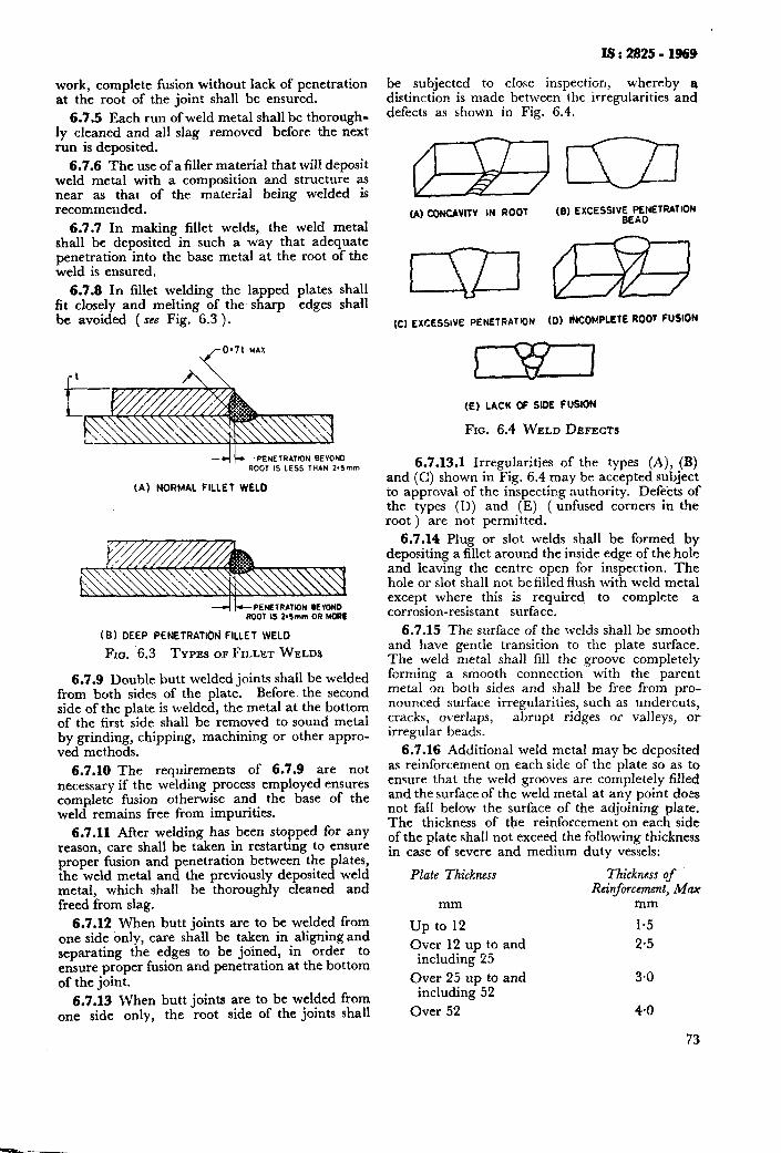
IS : 2825 - 1969
work, complete fusion without lack of penetration at the root of the joint shall be ensured.
6.7.5 Each run of weld metal shall be thorough- ly cleaned and all slag removed before the next run is deposited.
6.7.6 The use of a filler material that will deposit weld metal with a composition and structure as near as that of the material being welded is recommended.
6.7.7 In making fillet welds, the weld metal shall be deposited in such a way that adequate penetration into the base metal at the root of the weld is ensured,
6.7.8 In fillet welding the la ped plates shall frt closely and melting of the s R arp edges shall be avoided ( see Fig. 6.3 ).
0’71 WAX
PENETRATION BEV@ND ROOT IS LESS THAN 2*5mm
(A) NORMAL FILLET WELD
--I +PENETAATW)N BEYOND ROOT IS 2*Smm OR MOW
(B) DEEP PENEfRATlOFi FILLET WELD
Ao. 6.3 TYPES OF FILLET WELDS
6.7.9 Double butt welded joints shall be welded from both sides of the plate. Before. the second side of the plate is welded, the metal at the bottom of the first side shall be removed to sound metal by grinding, chipping, machining or other appro- ved methods.
6.7.10 The requirements of 6.7.9 are not necessary if the welding process employed ensures complete fusion otherwise and the base of the weld remains free from impurities.
6.7.11 After welding has been stopped for any reason, care shall be taken in restarting to ensure proper fusion and penetration between the plates, the weld metal and the previously deposited weld metal, which shall be thoroughly cleaned and freed from slag.
6.7.12 When butt joints are to be welded from one side only, care shall be taken in aligning and separating the edges to be joined, in order to ensure proper fusion and penetration at the bottom of the joint.
6.7.13 When butt joints are to be welded from one side only, the root side of the joints shall
be subjected to cIose inspection, whereby a distinction is made between the irregularities and defects as shown in Fig. 6.4.
(A) CWCAVIlV IN ROOT (8) EXCESSIV$..ETRATiON
(C) EXCESSIVE PENETRATION (D) INCOt4PLEtE ROOT FUSION
(E) LACK OF SIDE FUSION
FIG. 6.4 WELD DEFECTS
6.7.13.1 Irregularities of the types (A), (B) and (C) shown in Fig. 6.4 may be accepted subject to approval of the inspecting authority. Defects of the types (D) and (E) ( unfused corners in the root ) are not permitted.
6.7.14 Plug or slot welds shall be formed by depositing a fillet around the inside edge of the hole and leaving the centre open for inspection. The hole or slot shall not be filled flush with weld metal except where this is required to complete a corrosion-resistant surface.
6.7.15 The surface of the welds shall be smooth and have gentle transition to the plate surface. The weld metal shall fill the groove completely forming a smooth connection with the parent metal on both sides and shall be free from pro- nounced surface irregularities, such as undercuts, cracks, overlaps, abrupt ridges or valleys, or irregular beads.
6.7.16 Additional weld metal may be deposited as reinforcement on each side of the plate so as to ensure that the weld grooves are completely filled and the surface of the weld metal at any point does not fall below the surface of the adjoining plate. The thickness of the reinforcement on each side of the plate shall not exceed the following thickness in case of severe and medium duty vessels:
Plate Thickness Thickness of Reinforcement, Max
mm mm
up to 12 1.5
Over 12 up to and 2.5 including 25
Over 25 up to and 3.0 including 52
Over 52 4.0
73
IS : 2825 - 1969
In case of light duty vessels, the reinforcement shail he not more than 5 mm.
6.7.17 The reinforcement need not be removed except when it exceeds permissible thickness or when required under 8.7,
6.7.18 Cracks, lack of fusion, undercutting, incomplete root fusion, porosity or slag inclusions, which affect the strength of welded joints shall not he permitted beyond the limits permitted in 8.7.5.3 and 8.7.5.4.
6.7.19 Tf backing strip is used, it shall be of such material that it dues not influence the weld adversely. Wherever possible the backiqg strip shall be removed after \\.elding but @ior to carrying out the required non-destructive tests ( see 8.7 1.
6.7.28 If backing rings or cocsumable insert backing rings are used for pipes and tubes, these shall be of such material and design and be so fitted that their use does not cause defect in the ’ weld. If non-consumable Sacking rings are left in place these shall be properly secured and when necessary they shall have a contour OII the inside to minimize the restriction to flow and permit the passage of a tube cleaner.
6.7.21 If the pipe or tube wall is recessed for a backing ring, the depth of such recess shall be so limited that the remaining net section of the wall shall be at least equal to that required for the pipe or tube. A diminution of thickness of not more than 0.8 mm is allowable if compensation is made for it by an equivalent increase in the reinforce- ment of the weld.
6.7.22 Not less than two runs of weld metal shall be deposited at each xvrld affixing branch pipes, flanges and seatings.
6.7.23 It is recommended that whilt. finish- ing or dressing welds it shall be ansured that unavoidable scratches arising in the finishing or dressing process run parallel with the dircc- tion of greatest tensile stress in the weld due to tlie internal or external pressure or form an angle not exceeding 45”. While chipping and qrindinc care is to be taken that cracks, local indcntaiions or hardening effects do not arise.
6.7.24 Circumferential joints of headers, pipes and tubes of small diameters aye permitted to be welded from one side only, with or without backing strips. The design of the joint and the method of Melding shall provide full penetration and it shall be demonstrated by a qualification test and/or radiography that the welding method produced a weld that is free from significant defects.
6.7.25 All persons engaged in welding of pres- sure vessels shall ,be gdequately protected and the safety r:quiremcnts stipuiated in IS : 81%1957* and IS : X16-1965t shall be complied with.
‘Codr c;f prncticc~ for safety and health rrquiremcnts in rlcctlic and gas welding and cutting operations.
tCcjde of ;xxtice for ‘fire precautions in \vclding and cutting operations.
6.7.26 Arc flashes should be ground out and welds used for the attachment of erection cleats should be ground flush with the plate surface.
6.7.27 In case of vessels required to operate at low temperatures the ends of branch pipes and other openings in the vessels shall be ground to a smooth radius after all welding is complete.
6.7.28 The method of welding steel clad with the corrosion-resistant linings is given in Appendix J for information.
6.8 Welding of Non-ferrous Metals
6.8.1 Gas CVrlding - The commonly used gas processes for welding aluminium-base materials employ oxy-hydrogen or oxy-acetylene flames whereas only the latter produces suficient heat for welding the copper-base and nickel-base ailoys. For the aluminium-nickel and cupro- nickel alloys a neutral to slightly reducing flame should be used, whereas for copper-base materials the flame should be neutral to slightly oxidizing. A suitable flux, applied to the welding rod and the work, shall be used except that no flux is required for nickel. Boron-free and phosphorus-free fluxes are required for nickel-copper alloys and for nickel- chromium-iron alloys. shall be removed.
Residual deposits of flux
6.8.2 Metal-Arc Welding - Metal-arc welds may be made with standard dc equipment using reversed polarity ( electrode-positive ) and co- vered electrodes. A slightly greater included angle in butt welds for adequate manipulation of the electrode is required.
6.8.3 Inert-Gas M&al-Arc Welding - Both the consumable and non-consumable electrode pro- cesses are particularly advantageous for use with the non-ferrous materials. Best results are obtain- ed through the LIX of special filler metals ( see also IS : 2812-1964* and IS: 2680-1964t ).
6.8.4 Resistance Welding - Electric resistance welding, which inciudes spot, line or seam, and butt or flash welding, may be used with the non- ferrous materials. Proper equipment and tech- nique are reyuired for making satisfactory welds.
6.9 Rectification of Welds
6.9.1 Visible defects, such as cracks, pinholes and incomplete fusion and defects detected by the pressure test or by the examinations prescribed in 8.7.1, 8.7.2 and 8.7.11, shall be repaired by removing the defective material by grinding, chip- ping, machining, flame gouging or other approved methods to sound metal, and re-welding, care being taken to ensure proper penetration and com- plete fusion of the fresh weld deposit with the plates and previously deposited weld metal.
NOTE - The wrlding proccdurc for repairing the. era ks ruggcsted here is non-mandatory and is subjected
*Kwxmnendations for manual tungsten inert-gas arc- welding of aluminium and aluminium alloys.
+Fillrr rods and wres for inert gas tungsten arc welding.
to the approval of the inspecting authurity. A hole of about 10 mm diameter, depending on the plate thickness is drilled and countersunk at each end. The edge of the hole shall be about 50 mm away from either end of the crack. The distancr between the h&s &all be opened out by a V- or U-groove to the required depth and rr~eldrd. The holes shall be fil!ed last. It shall be rnsurctl by radiographic examination that no further crack ha5 drveluped and the I;ortion thus repaired meets the requiremer.t of this code.
6.9.l.i Repairs to welded joint cracks and to minor plate defects may be made after chipping out a I.;- or \‘-groove to full depth and length of the crack and tillmg this groove with weld metal deposited in accordance with 6.7.
6.9.2 When repeated repairs are to be carried out on the same part of a welded joint, adequate precautions shall be takeu to avoid a detrimental accumulation of residtral stresses.
6.9.3 If tlrc defects form a continuous line, the extrnt of repair shall be agreed upon between the marruf.rc.turc.r ar:d the inspecting authority.
6.9.4 All repairs carried out by the man&c- ttner OII a finished vessel shall be reported to the inspeiting authority. On completion of welded repairs, the manufacturer sha!l, ifrequested, supply fi,r rec;)~-d purpc,sr report of all repairs. No repair shalt 1~ carried out without prior approval of tire itlsl)ceting authority.
6.9.4.1 When repairs are carried out because of defects found by a radiographic examination, all the radiographs causing the demand for repair shall be kept on record and placed before the inspectirrg authority upon recluest.
6.10 Repair of Drilled Holes -- Hoier drilled throttgtl the vessel wall for measuring thickness should be closed by welding w-ith penetration for the full depth of the hole. Alternatively, these holes may bc treated as unreinforced openings and closed by any method permitted under the rules specified in this code.
6.11 Repair of Cracks - Cracks or grooving in plates on which forming operations have been carried out may be removed to sound metal and welded subject to prior agreement between the purchaser and the inspecting authority.
6.12 Post Weld Heat Treatment
6.12.1 Post weld heat treatment shall be carried out as the last operation prior to the prcssurr test in the case af carbon and low alloy ferritic steels either by normalizing or by stress- relieving. Special heat treatment in the case of high alloy steels and in the case of non-ferrous metals lvhere nrcessary shall be subject to agreement between the manufacturer and the in\pc~cting authority.
6.12.2 Vessels or parts of vessels fabricated from carbon and low alloy steels shall be thermally
IS : 2825 - 1969
stress-relieved by one of the procedures given in 6.12.3 when:
4
b) cl
4
e)
f )
4
intended for conta:_sing toxic or inflarn- mable material;
intended for operation below 0°C;
intended for use with media liable to cause stress corrosion cracking;
subjected to excessive local stress concen- tration which may give rise to cracking or subjected to changmg loads and subsequent risk of fatigue failures;
risk of brittle fracture due to the combined influence of material, transition tempera- ture, notch effect, etc;
it is necessary to maintain dimensional accuracy and shape in service; and
the plate thickness including corrosion allowance, at any welded joint in the vessel shell or head, exceeds the values given in Table 6.3 for various groups of materials.
6.12.2.1 When the welded joint connects plates that are of different rhickness the plate thickness to be used in applying the requirements of stress-relieving in 6.12.2 (gj shall be the following:
a) The thinner of two adjacent butt welded plates including head to shell connections;
b) The thicker of the shell or head plate, in connections to intermediate heads;
c) The thickness of the shell in connections to tube sheets or similar constructions; and
d) The thickness of the shell or head plate in nozzle attachment welds.
6.12.2.2 All welding of connections and attachments shall be stress-relieved when the vessel or par! thereof is required to be stress-relieved ( see Table 6.3 j.
6.12.2.3 Heat treatment should be carried out after all welded connections have been at- tached to the vessel. When welding repairs have been done to a vessel which has been earlier heat- treated, the vessel shall be heat-treated again, unless such rectifications are of very minor nature.
6.12.2.4 Stress-relieving, when required, shall be done before the hydrostatic test and after any repairs to welding. A preliminary hydrostatic test at a pressure not exceeding 0.5 times the design pressure to reveal leaks prior to the stress- relieving operation is permissible.
6.12.2.5 Normalizing is desirable when a structural improvement is necessary as with pressure vessels that are subjected to blows and knocks. When weldinLg pressure vessels that are to be normalized, the hl!er metal used shail be of the type, that the weld deposit will, after normaliz- ing, meet the same requi,rements regarding the yield point as the parent metal. Considerations should be given to the deformations or stresses
75
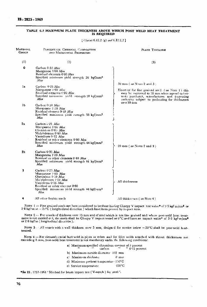
IS : 2825 - 1969
TABLE 6.3 M_QXIMUM PLATE THICKNESS ABOVE WHICH POST WELD HEAT TREATMENT IS REQIJIRED
: C‘latiscs 6.12.2 (g) ad 6.12.2.21
MATERIAL PARENTAGE C~~EMKXL C~VPOSIT~~N GROUP AND MECHANICAL PROPERTIE*
(1)
0
(2)
Carbon 0.2\) Max Manganese I%0 Max Residual elements 0.80 Max Specified minimum yield strer@l 26 kgf/mms &fax
la Carbon 0.25 Max Manganese 1 +i(1 Mu K&dual elenxnts C.80 MUX Specified mirLn\:m yield strength 38 kgf/mmz
MCI.-4
Ib Carbon 0.3!1 Mu Maoganesr i.20 A&x Residual element 0.10 MQX Spe;lfied minimum yield strength 38 kgf/mm2
2a Carbon 2.25 Max Mxganesc 1% Mu Ch!omium 0.63 MUX Molybdenum 0.60 Max Vanadium 0.12 MUX Residual or other elements 0.80 Mcx Specified minimum yield strength 44 kgf/m&
Ml2.X
2b Carbon 0.35 Mar Manganese 1.20 Max Residual or other elements 0.40 Max Szzfied minimum yield strength 44 kgf/mms
Carbon O-25 Mar Manganese i%_l Max Chromium 1.10 MGX Molybdenum 1.50 MUX Vanadium 0.16 Max Residual or other clerrlent O%O Specified minimum yirld streilgth 44 kgf/mms
Al! other ferritic steels All thicknt-rsrs ( ;ec Note 4 )
PLATE THICXWESS
(3)
31) mm ( JW Notes 2 and 3 :
Howe.!er for fine grained ste.1. lsce Note 1 ) this may be incrrascd to 38 mm when agrred to bet- wee:) purcl,aser, manufacturer and inrpecting authority subject to preheating for :hicknesses over 30 mm
20 mm ( SM Notes 2 and 3 )
All thicknesses
Nom 1 - Fine grained steels are here considered to be those having C!larpy V impact test value* ofY.5 kgfm/cms or 2’8 kgfm at -20°C ( longitudinal direction ) which have been proved by impact testi.
R’OTE 2 - For vessels cf thickness over 15 mm and of steel which is not fine grained and whrre post-weld heat treat- ment is not carried ol!t, the steels shall be Charpy V impsct tested at 0°C and have an impact value* of 3.5 kgfm/cma or 2.8 kgPm (longitudina! direction).
NOTE 3-- A!1 vessels with a wall thickness over 5 mm, designed for service below --20°C shall be post-weld heat- treated.
NOTE 4 - For circumrelential butt weld in pipes or tubes and for fillet welds attached with throat thicknesses not exceeding 8 mm, post-weld heat treatment is not mandatory under the following conditions:
a) Maximum specified chromium content of 3 percent ,t >, carbon >I ” 0.15 percent
b) Maximum outside dii:mcter 102 mm c! Maximllm thickness P mm
d) Minimum preheat tcmperatur,. 150°C
e) Service temperature 450°C
*See IS. 1757-1961 ‘ Method for beam impact test ( V-notch ) for steel ‘.
76
arising with the heating and cooling associated with the normalizing process.
6.12.2.6 A normalizing heat treatment before or after \*;elding is required for hot-formed parts unless the process of hot-fbrming was carried out within a temperature range corresponding to normalizing.
6.12.3 Procedure for Thermal Stress Relief - The operation of thermal stress-relieving shall be performed in accordance with the requirements given in 6.12.2 using one of the following pro- cedures.
6.12.3.1 The vessel shall be stress-relieved by heating as a whole in an enclosed furnace wherever practicable. Where it is not practicable to stress-relieve the entire vessel in one operation, the following’ procedures may be adopted. It may, however, be noted that these procedures may not ensure the same degree of immunity from susceptibility to stress corrosion cracking:
a>
b)
4
4
The vessel is heated in sections in an en- closed furnace, the minimum overlap of the heated sections being 1.5 m. Where this method is adopted, the vessel portion pro- jecting outside the furnace shall be suitably shielded so that the temperature gradient is not harmful. Circumferential seams in shells, piping and other tubular products may be locally stress-relieved by heating uniformly a shielded circumferential band around the entire circumference. The w,idth of the heat- ed band shall be not less than 5 &?, where r and t are the radius and the thickness of the part stress-relieved, the weld being in the centre of the band. Sufficient in- sulation shall be provided to ensure that the temperature of the weld and heat affect- ed zone is not less than that specified and the temperature at the edge of the heated band is not less than half the peak tem- perature. In addition the adjacent portion of the material outside the heated zone shall be protected by means of thermal in- sulation so that the temperature gradient is not harmful. A minimum width of insula- tion of 10 d/;t is recommended for the purpose of meeting these requirements.
The vessel may also be heated internally for heat treatment, in which case the vessel shall be fully encased with insulating ma- terial. The internal pressure should be kept as low as possible and should not be such as to cause appreciable deformation at the highest metal temperature expected during heat treatment.
Shell sections or any other portion of a vessel may be heated to stress-relieve Iongi- tudinal joints or complicated welded details before being joined to make the completed vessel. When it is not practicable to stresr- relieve thd completed vessel as a whole ox
4
IS : 2825 - 1969
in two or more parts as provided, any cir- cumferential joint not previously stress- relieved may be thereafter locally stress- relieved after welding the closing joints, by heating such joints by any appropriate means that will assure the required uni- formity. The width of the heated band shall be not less than 2*5d%. The portion outside the heating device sha!l be protected so that the temperature gradient is not harmful. This procedure may also be used to stress-relieve portions of new vessels after repairs.
Branches, nozzles or other welded attach- ments may be locally stress-relieved by heating a shielded circumferential band. The band shall be heated up uniformly to the required temperature and held for the specified time. The circumferential band shall extend around the entire vessel, shall include the nozzle or welded attachment, and shall extend at least 2_52/rtbeyond the welding which connects the nozzle or other attachment to the vessel. The portion of the vessel outside of the circumferential band shall be protected so that the tempera- ture gradient is not harmful. A minimum width of insulation of 2.51/r-?on either side of the heated band is recommended.
6.12.3.2 Where a welded production test plate is required, it shall be placed inside the drum during heat treatment, or where this is impracti- cable, the test plate may be placed alongside the drum in the furnace in such a position that it will receive similar heat treatment.
The test plate may be heat-treated separately from the drum provided that means are adopted to ensure that the conditions are the same for the test plate as for the drum, namely, rate of heating, maximum temperature, soaking temperature, soaking time, and rate of cooling.
6.12.4 Stress-relieving of welded pressure parts shall be effected by any of the following methods.
6.12.4.1 The temperature to which the material shall be heated for stress-relieving pur- poses shall be within 580” to 620°C with the following requirements:
a) The temperature of the furnace at the time the vessel is placed in it shall not exceed 300°C.
b) The rate of heating above 300°C shall not exceed 220 deg per hour up to and includ- ing 25 mm shell or end plate thickness. For shell or end plate thickness over 25 mm the rate of heating above 300°C shall be
5 506 Max shell or end plate thickness in mm d eg per hour
or 55 deg per hour, whichever is greater.
c) During the heating period there shall not be a greater variation in temperature throughout the portion of the vessel being
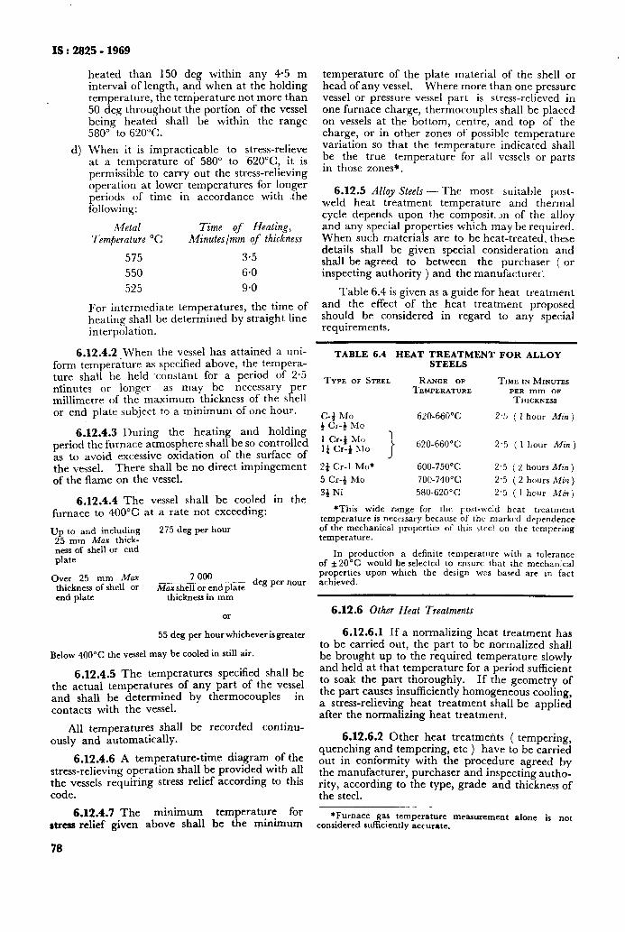
: 2825 - 1969 IS
heated than 150 deg within any 4.5 m interval of length, and when at the holding temperature, the temperature not more than 50 deg throughout the portion of the vessel being heated shall be within the range 580” to 620°C.
4 When it is impracticable to stress-relieve at a temperature of 580” to 62O”C, it is permissible to carry out the stress-relieving operation at lower temperatures for longer periods of time in accordance with the following:
Metal Time of Heating, Temperature “C Minutes/mm of thickness
575 3.5
550 6.0
525 9.0
For intermediate temperatures, the time of heating shall be determined by straight line interpolation.
6.12.4.2 When the vessel has attained a uni- form temperature as specified above, the tempera- ture shall be held ‘constant for a period of 2.5 minutes or longer as may be necessary per millimetre of the maximum thickness of the shell or end plate subject to a minimum of one hour.
TABLE 6.4 HEAT TREATMENT FOB ALLOY STEELS
TYPE OF STEEL RANGE OF TIME IN MINUTES TEMPERATURE PER mm OF
THICKNESS
6.12.4.3 During the heating and holding period the furnace atmosphere shall be so controlled as to avoid excessive oxidation of the surface of the vessel. There shall be no direct impingement of the flame on the vessel.
C-4 MO 4 Cr-zJ MO
1 Cr-4 Mo I& Cr-+ hlo
_ 620~6tiW’C
620-660°C
2.3 ( I hour Min)
2.5 ( 1 hour Min)
6.12.4.4 The vessel shall be cooled in the furnace to 400°C at a rate not exceeding:
2f Cr-1 Mo* 600-750% 2.5 ( 2 hours Min)
5 Cr-4 MO 700-740°C 2.5 ( 2 hours Min )
34 Ni 580-62O’C 2.5 ( 1 hour Minj
*This wide range for the Iost-weld heat treatment
Up to and including 275 deg per hour 25 mm Max thick- ness of shell or end plate
temperature is necessary because of the marked dependence of the mechanical properties of this strel on the tempering temperature.
Over 25 mm Max thickness of shell or end plate
7 000
Max shell or end plate deg per hour
thickness in mm
OI
In production a definite temperature with a tolerance of *20°C would be selected to ensure that the mechanical properties upon which the design WDS based are in fact achieved.
6.12.6 Other Heat Treatments
55 deg per hour whicheverisgreater
Below 400°C the vessel may be cooled in still air.
6.12.4.5 The temperatures specified shall be the actual temperatures of any part of the vessel and shall be determined by thermocouples in contacts with the vessel.
6.12.6.1 If a normalizing heat treatment has to be carried out, the part to be normalized shall be brought up to the required temperature slowly and held at that temperature for a period sufficient to soak the part thoroughly. If the geometry of the part causes insufficiently homogeneous cooling, a stress-relieving heat treatment shall be applied after the normalizing heat treatment.
All temperatures shall be recorded continu- ously and automatically.
6.12.4.6 A temperature-time diagram of the stress-relieving operation shall be provided with all the vessels requiring stress relief according to this code.
6.12.6.2 Other heat treatments ( tempering, quenching and tempering, etc ) have to be carried out in conformity with the procedure agreed by the manufacturer, purchaser and inspecting autho- rity, according to the type, grade and thickness of the steel.
6.12.4.7 The minimum temperature for atress relief given above shall be the minimum
*Furnace gas temperature measurement alone is not considered sufficiently accurate.
78
temperature of the plate material of the shell or head of any vessel. Where more than one pressure vessel or pressure vessel part is stress-relieved in one furnace charge, thermocouples shall be placed on vessels at the bottom, centre, and top of the charge, or in other zones of possible temperature variation so that the temperature indicated shall be the true temperature for all vessels or parts in those zones*.
6.12.5 Alloy Steels - The most suitable post- weld heat treatment temperature and thermal cycle depends upon the compositm of the alloy and any special properties which may be required. When such materials are to be heat-treated, these details shall be given special consideration and shall be agreed to between the purchaser ( or inspecting authority ) and the manufacturer’.
Table 6.4 is given as a guide for heat treatment and the effect of the heat treatment proposed should be considered in regard to any special requirements.
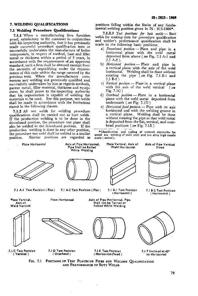
IS:2825-1969
7. WELDING QUALIFICATIONS positions falling within the limits of any funda-
7.1 Welding Procedure Qualifications Qental welding position given in IS : 815-1966*.
7.1.1 When a manufacturing firm furnishes 7.1.2.1 Test positions for butt wcldr - Butt
proof, satisfactory to the customer in conjunction welds for making tests for procedure qualification
with his inspectibg authority, that it has previously and welder’s performance qua!ification shall be
made successful procedure qualification tests or made
successfully undertaken the manufacture of boiler a) components, in respect of method, base and filler metal or thickness within a period of 3 years, in accordance with the requirements of an approved standard, such a firm shall be deemed exempt from the necessity of requalifying under the require- ments of this code within the range covered by the previous tests. When the manufacturer com- mences any welding not previously qualified and succkssfully undertaken by him as regards methods, parent metal, filler material, thickness and equip- ment, he shall prove to the inspecting authority that his organization is capable of welding the materials to be used. For this purpose, test welds shall be made in accordance with the limitations stated in the following clauses.
7.1.2 All test welds for welding procedure
b)
in the f6llowing basic-positions: Downhand position-Plate and pipe in a horizontal plane with the weld metal deposited from above ( see Fig. 7.1 A-l and 7.1 A-2).
c)
d)
e)
qualifications shall be, carried out as butt welds, If the production welding is to be done in the downhand position, the procedure test plate shall also be welded in the downhand position. If the
Horizontal position - Plate and pipe in a vertical plane with the axis of the weld horizontal. Welding shall be done without rotating the pipe 7 see Fig. 7.1 B-l and 7.1 B-2 ) Vertical ‘position - Plate in a vertical plane with the axis of the weld vertical Fig. 7.lC)
( se#
Overhead position - Plate in a horizontal plane with the weld metal deposited from underneath ( see Fig. 7.1 D ) Horizontaljixed position - Pipe with its axis horizontal and with the welding groove in a vertical plane. Welding shall be done without rotating the pipe so that weld metal is deposited from the flat, vertical, and over- head positions ( see Fig. 7.1 E )
production welding is done in any orher position, ____- the procedure test weld shall be welded in a similar *Classification and coding of covered electrodes for
position. metal arc welding of mild steel and low alloy high tensile
Similar positions are regarded as steels ( ~CU~JC~).
Plate Horizontal Axis of Pipe Horizontal, Plate Vertical, Axis of Pipe Shall be Rolled Weld Horizontal
Axis of Pipe Vertical Fixed
While Welding
& 00> @ 8
7.1 A-l Test Position ( Flat ) 7.1 A-2 Test Position ( Flat ) 7.1 B-I Test Position 7.1 B-2 Test Position
Dlate Vertical, Axis of
Weld Vertical
7.1 C Test Position ( Vertical )
Plate Horizontal
( Horizontal )
Axis of Pipe Horizontal, Pipe Shall not be Turned or Rolled While Welding
( Horizontal )
7.1 D Test Posltlon 7.1 E Test Position ( Overhead ) ( Horizontal-fixed )
7.1 F Inclined at 45” to Horizontal
FIG. 7.1 POSITIONS OF TEST PLATES OR PIPES FOR WELDER QUALIFICATION AND PERFORMANCE OF BUTT WELDS
79
. .
IS : 2825 - 1969
An additional test position in case of butt welded pipes is the pipe inclined at 45°C to the horizontal ( see Fig. 7.1 F ).
7.1.2.2 Qualification in the horizontal, verti- cal, or overhead position shall qualify also for the downhand position. Qualification in the horizontal fixed position, shall qualify for the dawnhand, vertical, and overhead positions. For pipes quali- fication in the horizontal, vertical and overhead positions shall qualify for all positions.
7.1.3 Apart from what is specified in 7.1.X and 7.1.2, procedure qualification test welds for all preSsure parts of pressure vessels shall be made in such a manner that the welds are considered representative of those made in production, taking into account the following essential variables.
7.1.3.1 T_@c of parent metal
a) S/~el -‘The procedure qualification test plates or test pipes shall be made from steel with a tensile stren,gth in the same range as that of the steel to be used in the construction and a chemical composition approximately corresponding to the most unfavourable analysis from the standpoint of weldability and within the limits of the material specification of the steel concerned. A procedure qualification made on steel with a certain tensile strength and a certain chemical analysis shall also cover the use of steels having a lower strength and a more favourable chemical analysis. In the case of plain carbon or carbon-manganese or alloy steels, these requirements are considered to be met, as long as the steel used for pro- duction and for the procedure qualification, both fall within the limits of one of the follo\vin,g groups:
i) Low alloy and carbon steels
1. Grade St 42 IS : 226-1962 Specification for structural steel ( standard quality )
2.
3.
4.
5.
6.
7.
8.
( third. revision )
Grade St 55-HTW IS : 961-1962 Speci- fication for structural steel ( high tensile ) (Jirst revision )
Grade St 42 W IS : 2062-1962 Specifica- tion for structural steel ( fusion welding quality )
Grade Cl5Mn75 IS : 1570-1961 Sche- dules for wrought steels for general engineering purposes
IS : 2041-1962 Specification for steel plates for pressure vessels
Grade 20Mo5,5 IS : 1570-I 961 Schedules for wrought steels for general engineering purposes_
IS : 2002-1962 Specification for steel plates for boilers
iii) High alloy corrosk~ and heat resistant steels
1. Grade 07Crl3 IS : 1570-1961*
2. Grade 04Crl9Ni9 IS : 1570-1961*
3. Grade 04GrlSNiSTi?&! IS : l570-196l*
4. Grade 04Crl9Ni9N@ IS : 1570-196li*
5. p9r;Fl 07Crl9Ni9Mo2T@ IS : 1570-
6. Grade 05Crl8Nil lMo3 IS : 1570-1961*
7. Grade 05Crl8NillMo3Tiz IS : 1576- 1961*
8. Grade lOCr25Nil8 IS : 1570-1961*
Qualification in material of a higher alloy roup also qualifies for material of a lower alloy gr $ up.
b) Non-ferrous metals - Whenever I welding of non-ferrous metals is undertaken, the manufacturer shall prove to the inspecting authority that the weldwg is successfully
Grades 1 and 2 of IS : 3038-1965 Specification for alloy steel castings for
*Schedules for wrought steels for general engineering P"rp-.
9.
10.
11.
12.
13.
14.
15.
pressure containing parts suitable for high temperature service ( fusion weld- ing quality )
IS : 1914-1961 Specification for carbon steel boiler tubes and superheater tubes
IS : 2416-1963 Specification for boiler and superheater tubes for marine and naval purposes
IS : 2004-1962 Specification for carbon steel forgings for general engineering purposes
IS : 3039-1965 Specification for struc- tural steel ( shipbuilding quality )
IS : 3503-1966 Specification for steel for marine boilers marine pressure vessels and welded machinery structures
IS : 3945-1966 Specification for steel fir naval purposes
Carbon and carbon-manganese steels conforming to material group 0 and 1 of Table 6.3 except those used for low temperature operation.
NOTE - Carbon over 0.23 percent is rubject to agree- ment between the manufacturer and the inspecting authority. In these caseS preheating is recommended.
ii) Alloy steels ( other than high alloy heat resisting and stainless steels )
Alloy steels conforming to material group 2, 3 and 4 of Table 6.3 and group 0 and group 1 steels to be used at low temperatures
IS : 3609 - 1966 Specification for chrome molybdenum steel, seamless boiler and superheater tubes
IS : 2611 - 1964 Specification for carbon chromium molybdenum steel forgings for high temperature service.
IS : 2825 - 1969
undertaken by him as regards methods, filler metals, thickness of parent metal and equipment. For this purpose test welds shall be made in accordance with the limitations as agreed to between the manufacturer and the inspecting authority.
c) Type and number of test specimens-The type and number of test specimens that shall be tested to qualify a procedure qualifica- tion are. given in Table 7.1 together with the range of thickness that is qualified for use in construction by a given thickness of test plate or pipe used in making the qualification. Qualification on pipe shall qualify for plate but not vice versa. The test specimens shall be removed in the order shown in Fig. 7.2 to 7.6.
d) Welds between different base metals-When joints are made between two different types of base metal, a tielding procedure qualification shall be made for the appli- cable combination of materials even though procedure qualification tests have been made for each of the two types of base metals welded to itself.
7.1.3.2 Electrodes, Jiller ro&, JIux and shielding gas - The specification and if there is no suitable specification, the type and mark of electrode and the composition of the filler rods, flux and shield- ing gas, shall be the same for the procedure quali- fication and production welds.
7.1.3.3 Type of joint preparation - For manual metal arc welding process, the type of joint pre- paration, for example, single V, double V, single U, double U or square edge, may be changed in production welds without the necessity of making a new procedure qualification test, provided that the form of the preparation is in agreement with good practice. For semi-automatic or automatic welding process, any important change in edge preparation requires a new procedure qualification.
7.1.3.4 Welding technique - A new procedure qualification test shall be required:
4
b)
Cl
4
e)
f)
if in metal arc welding with covered electrodes a change in the type of electrode or a change in the composition of the weld metal, and in gas welding, a change in filler metal type or a change in weld metal composition is made;
if in arc welding a change is made from dc source to ac or vice versa;
if in arc welding of single welded butt joints a backing strip is added or omitted;
if in oxy-acetylene welding of single welded butt joints a backing strip is added;
if in machine welding a change is made from multiple pass welding per side to single pass welding per side;
if in submerged arc welding, a change is made from a filler metal containing l-75 to 2.25 percent manganese to filler metal
containing less than one percent manganese or vice versa ( the presence of 0.5 percent molybdenum in the filler metal analysis shall not require requalification );
g) if in submerged arc-welding, a change is made in the tiommal composition or type of flux used or a change is made in filler metal analysis ( requalification is not required for the change in f JX particle size );
NOTE - In submerged arc-welding, where the’ alloy content of the we!d metal is largely dependent upon the composition ofthe flux used, any change in any part of the welding procedure which would result in the impor- tant alloying elements in the tieId metal being outside the specification range of chemistry given in the welding procedure specification. If there is evidence that pro- duction welds are not being made in accordance with the procedure specifications, the inspector may require that a check be made on the chemical composition of the weld metal, Such a check shall preferably be made on a production weld.
h) if in inert gas metal arc welding a change is made in the composition of the gas and a change in the electrode from one type to another or from non-consumable electrode to consumable electrode and vice versa.
7.1.3.5 Welding process - The welding process and, in the case of manual semi-automatic or automatic welding, the type of welding device shall be the same for the procedure qualification test and for the production welds. When the root pass of combination welds is made by one pro- cess and the remaining portion of the groove by another process, a new procedure qualification test is required.
7.1.3.6 Preheating and delayed cooling - The temperature of preheating, and heat treatment immediately following welding and any control of cooling rate, shall be the same for the procedure qualification test and for the production welds. However, if the preheat temperature in production work is increased by less than 100°C this change will not necessitate a new procedure qualification test.
7.1.3.7 Subsequent heat treatment - The subse- quent heat treatment shall be the same for the welding procedure test and the production welds.
7.1.4 For metal arc welding, a procedure quali- fication shall be valid for thickness from 0.75 to I.5 times the thickness of the procedure quali- fication test piece in plate or pipe. For oxy- acetylene welding the test piece thickness shall be the maximum thickness for which the procedure qualifications are valid.
7.1.5 The test pieces for procedure qualification for butt welds in plates shall be of sufficient size to provide for the following tests:
a) One reduced-section tensile test specimen cut transversely to the weld or as many specimens as are necessary to investigate the tensile strength over the whole thickness of the joint for all plate thicknesses ( see 8.5.7 ).
81
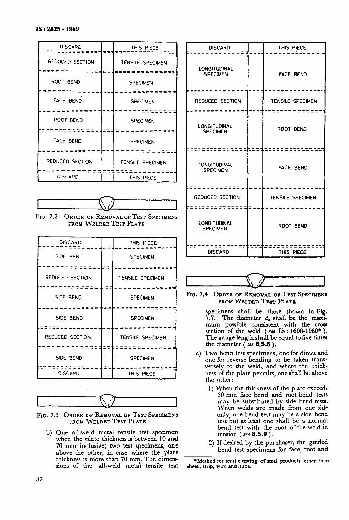
IS : 2825 - 1969
I REDUCED SECTION 1 1
I= ====1==5==== == : 1 1 I ROOT BEND
I I ============: -_= : FACE BEN6 11 ROOT BEND
I FACE BEND I I
F====-- --======q=q I I
REDUCED SECTION I I
tzi====== ====A==4
1 DISCARD I I_
THIS PIECE - --__-___---____ -_-_--___-____.
I Y
I FIG. 7.2 ORDER OF REMOVAL OF TEST SPECIMENS
FROM WELDED TEST PLATE
TENSILE SPECIMEN
----------_-__ __-_--_---__-_
SPECIMEN
SPECIMEN
___I ____ -_----. -----___--__-
SPECIMEN
-----------_-_ ---------_--
SPECIMEN ----_ __--_ --_--z=-_-__
TENSILE SPECIMEN --------_-_-- ---_ ---_;---__
THIS PIECE
DISCARD THIS PIECE -------- _________ _-- ----_--__-__----..=~ =======r====
SIDE BEND SPECIMEN
-_-_ _--_--_ ==L=======---_=_----___===========
REDUCED SECTION TENSILE SPECIMEN
._----_--_-__ . . - ------ ___-_ ._-_ --~_-_~-~._I-_--~--~~ _____
SIDE BEND SPECIMEN
-_-------__--~. - _----__--_ ___.. ==--_============
SIDE BEND SPECIMEN
__---_- --_- ----_-..- ------- _____ __---- - --_- ------._---- ---____ -_
REDUCED SECTION TENSILE SPECIMEN
----- _--- --_- ..____ - __-___ ._-- ----- _---_== .--_--_-_=______=
SIDE BEND SPECIMEN .--__-- ____ - __.. _ __-___--____-__ ==_------------- -- ---- -__-c__
DISCARD THIS PIECE
I V
I Fro. 7.3 ORDER OF REMOVAL OF TEST SPECIMENS
FROM WELDED TEST PLATE
b)
82.
One all-weld metal tensile test specimen when the plate thickness is between 10 and
DISCARD THIS PIECE - -___ --_-_____ ___.,___ -__-___--- -----___--_-__ ___..__ ____-- ____ -
LONGITUDINAL SPECIMEN FACE BEN3
----_-__---_-- -____ -__-----_-___. ----____------ _____ -_--__-_-_-__
REDUCED SECTION TENSILE SPECIMEN
------------____-__-__~~-----~~~ --- ----------_ -_______--- _______
LONGITUDINAL SPECIMEN ROOT BEND
-- -____ ---- ____ _ -___--____--__ --- ------- ----_ ==.._____- _____ ___
LONGITUDINAL SPECIMEN FACE BEND
____--__--__-_ -_-_ -- -- __ __-- -_ __ - - -_== = =========z
REDUCED SECTION TENSILE SPECIMEN
------- --- --_-__ -‘______---__-__ __---_-_---___--_._-~~-~~~-~~~~-
LONGITUDINAL SPECIMEN ROOT BEND
______-_---____ ___. ______-_______ ___---__ _ ---__.__ -______-_ _______ DISCARD THIS PIECE
I I FIG. 7.4 ORDER OF REMOVAL OF TEST SPECIMENS
Cl
FROM WELDED TEST PLATE
specimens shall be those shown in Fig. 7.7. The diameter d,, shall be the maxi- mum possible consistent with the cross section of the weld ( see IS : 1608-1960* ). The gauge length shall be equal to five times the diameter ( set 8.5.6 ).
Two bend test specimens, one for direct and one for reverse bending to be taken trans- versely to the weld, and where the thick- ness of the plate permits, one shall be above the
1)
other:
When the thickness of the plate exceeds 30 mm face bend and root bend tests may be substituted by side bend tests. When welds are made from one side only, one bend test may be a side bend test but at least one shall be a normal bend test with the root of the weld in tension ( see 8.5.9 ).
2) If desired by the purchaser, the guided bend test specimens for face, root and 70 mm inclusive; two test specimens, one
above the other, in case where the plate thickness is more than 70 mm. The dimen- sions of the all-weld metai tensile test
*Method for tensile testing of steel pmductr other than Sheet, atrip, wire and tube.
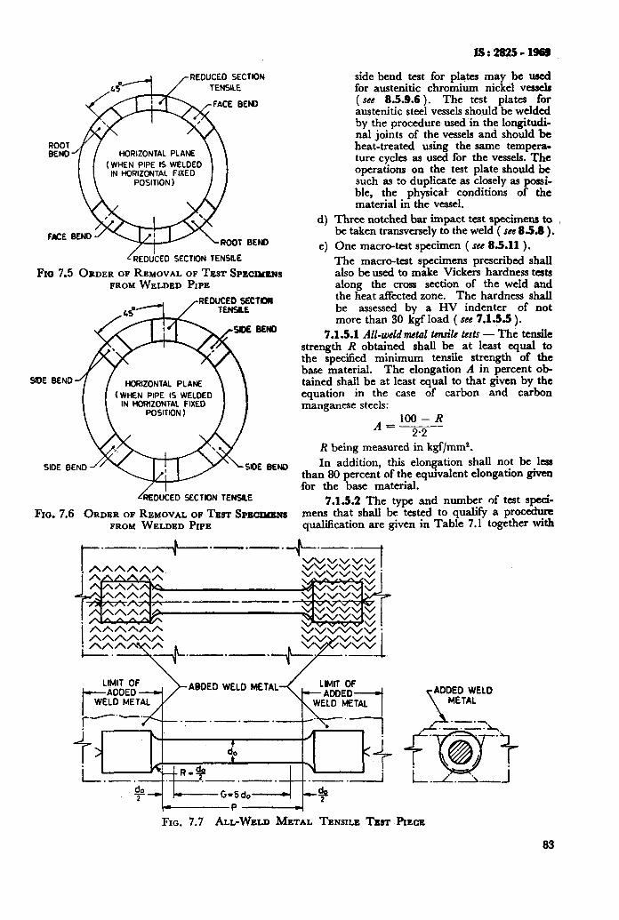
IS:282501999
REDUCED SECTION
HORIZONTAL PLANE
(WHEN PIPE IS WELDED wl HORIZONTAL FIXED
L RED&ED SECTION TENSILE
Fm 7.5 ORDER OF REMOVAL OF TEST SPECIUBNS FROM WELDED PIPE
REDUCE0 SECTIOR
HORIZONTAL PLANE
(WHEN PlPE IS WELDED IN HORIZONTAL FIXEO
SECTION TENSILE
Fro. 7.6 ORDER OF REMOVAL OF TEXT SPS~~ FROM WELDED PIPE
side bend test for plates may be used for austenitic chromium nickel vessels ( see 8.5.9.6 ). The test plates for austenitic steel vessels should be welded by the procedure used ‘in the longitudi~ nal joints of the vessels and should be heat-treated using the same tempera- ture cycles as used for the vessels. The operations on the test plate should be such as to duplicate as closely as possi- ble, the physicat conditions of the material in the vessel.
d) Three notched bar impact test specimens to be taken transversely to the weld ( see 83.8 ) .
e) One macro-test specimen ( see 8.5.11 ). The macro-test specimens prescribed shall also be used to make Vickers hardness tests along the cross section of the weld and the heat affected zone. The hardness shall be assessed by a HV indenter of not more than 30 kgf load ( see 7.1.5.5 ).
7.1.5.1 All-weld metal tensile tests - The tensile strength R obtained shall be at least equal to the specified minimum tensile strength of the base material. The elongation A in percent ob- tained shall be at least equal to that given by the equation in the case of carbon and carbon manganese steels:
A 100 - R
= ---m-- R being measured in kgf/mm*. In addition, this elongation shall not be less
than 80 percent of the equivalent elongation given for the base material.
7.1.5.2 The type and number of test speci- mens that shall be tested to qualify a procedure qualification are given in Table 7.1 together with
ADDED WELD METAL
FIG. 7.7 ALL-WELD METAL TENSILE TEST PIECE
83
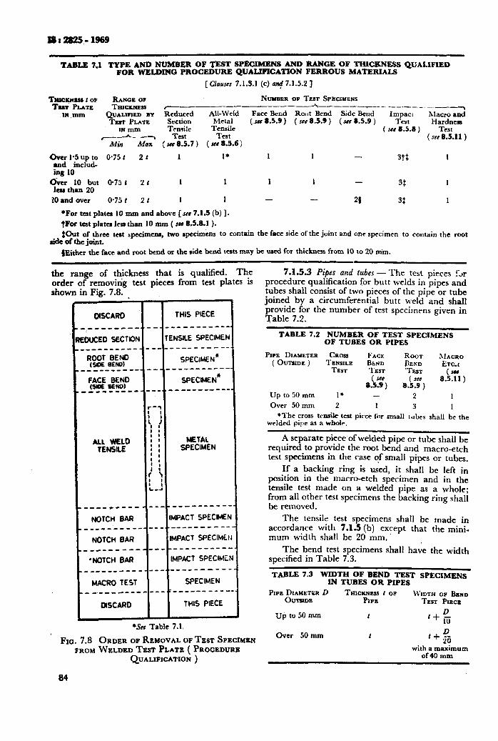
l8:2825-1969
TABLE 7.1 TYPE AND NUMBER OF TEST SPECIMEN 8 AND RANGE OF T?DCRNESS QUALIFIED FOR WELDING PROCEDURE QUALIFICATION FERROUS MATERIALS
[Clauses 7.1.3.1 (c) a* 7.1.X?]
RANGE op PU’UNBER OF TF.ST SPECIMENS THICKNESS r------- --* ------_--~--_-___ __-
m ,mm QUALIFIED BY Reduced All-Weld Face Ber.d Rout Bend Side Bend Macro and TEST PLATE Section Metal (MC 8.5.9) ( JCI 8.5.9 ) ( JCC 8.5.9 )
impact Test Hardness
IN mm TeXlde Tensile I *cc 8.5.8 ) Test c_-- -7 Test TrJt ( WC 8.5.11 )
Mill Max : SEC 8.5.7 ) ( s#e 8.5.6 j
%l*;IY$ 0*75r 2 t 1 1’ 1 1 - 3t+, 1 _
ing 10 C.&r*;; &I( 0.75 t 2 I 1 1 1 1 - 3$ 1
10 and over 0.75 t 2 t 1 1 - - 20 3: 1
*For tat plate1 10 mm and above [see 7.1.5 (b) 1. tFw test plata less than 10 mm ( III 8.5.8.1 ). $Out of three test specimens, two rpccimens to contain the face side of the joint and one specimen to contain the root
side of the j&t.
#Either the face and root bend or the side bend tests may be used for thickness from 10 to 20 min.
the range of thickness that is qualified. Th_e order of removirig test pieces from test plates 1s shown in Fig. 7.8. 1
MSCARD THIS PIECE
~-___-~--,,--~----- ------
EDUCED SECTIDN TENSILE SPECIMEN
.-__ ____ ^_______ mm_- _-_-..
“(“50: ZiY SPECIMEN*
_______ ____ -___--_ a ---- --
:Ag zEW,D SPECtMEN*
__ __-__ --_ ---..----- ------
_-L-F _---_--_ ~---------.
NOTCH BAR IMPACT SPECIMEF 4 _____ -____~-~-..----- m-c--
NOTCH BAR IMPACT SPECIMEI I ______ -_-_- ------------.
‘NOTCH BAR IMPACT SPECIME! N ______ _____--_, b_ ---- ----.
MACRO TEST SPECIMEN ,_ ,- ----_ __-__-_ -__- _____-
DISCARD THIS PIECE
1 *See Table 7.1,
Fro. 7.8 ORDER OF REMOVAL OF TEST SPECIMBN FROM WELDBD Tess PLATE ( PROCEDURE
QUALIFICATION )
84
7.1.5.3 Pipes and tubes-The test pieces Lr procedure qualification for butt welds in pipes and tubes shall consist of two pieces of the pipe or tube joined by a circumferential butt weld and shall provide for the number of test specimens given in Table 7.2.
TABLE 7.2 NUMBER OF TEST SPECIMENS OF TUBES OR PIPES
Prr~ DIAMETER CRoss FACE ROOT SIACRO ( OUTSIDE ) TENSILE BEND BEND ETCI
TEST TEST ‘TEST (III
8!&?) ( *cc
k5.9 ) 8.5.11)
IJp to 50 mm I* - 2 1 Over 50 mm 2 1 3 I
*The cross trnsik test pirce for small tubes shall be the welded pipe as a wholr.
A separate piece-of welded pipe or tube shall be required to provide the root bend and macro-etch test specimens in the case qf small pipes or tubes.
If a backing ring is used, it shall be left in position in the macro-etch specimen and in the tensile test made on a welded pipe as a whole; from all other test specimens the backing ring shall be removed.
The tensile test specimens shall be made in accordance with 7.1.3 (b) except that the mini- mum width shall be 20 mm..
The bend test specimens shall have the width specified in Table 7.3.
TABLE 7.3 WIDTH OF BEND TEST SPECIMENS 1N TUBES OR PIPES
PlPE$WTE3R D THKXNESS 1 OP WIDTH olr BKND PIPE TEST P~sca
Up to 50 mm D I+ 1%
Over 50 mm _~
with a maximum of 40 mm
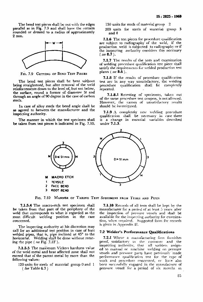
The bend test pieces shall be out with the edges parallel as in Fig. 7.9 and shall have the corners rounded or dressed to a radius of approximately 2 mm.
db Fr&. 7.9 CUTTING OP BEND TEST PIECES
The bend test pieces shall be bent \+thout being straightened, but after removal of the weld reinforcements down to the level of, but not below, the surface, round a former of diameter 3t and through an axigle of 90 degree in the case of carbon steels.
In case of alloy steels the bend angle shall be as agreed to between the manufacturer and the inspecting authority.
The mannei in which the test specimen shall be taken from test pieces is indicated in Fig, 7.10.
IS : 2825 - 1969
150 units for steels of material group 2
200 units for steels of material group 3 and 4
7.1.6 The test pieces for procedure qualification are subject to radiography of the weld, if the production weld is subjected to radiography nr if the inspecting authority considers this ncccssary ( see 8.7 ).
7.1.7 The results of the test3 and examination of welding proccdurE qualification test piece shall satisfy the requirements Tar welded production test plates ( see 8.6 ).
7.1.8 If the results of procedure qualification test are in any way unsatisfactory, the welding procedure qualification shall be complctc1y repeated.
7.1.8.1 Retesting of specimens, taken out of the same procedure test coupon, is not allowed. However, illC causes of unsatisfactory results should be investi:;ated.
7.1.9 h completely new \vclding procedure qualificirion shall be necessary in case there is a change in essential variables described under 7.1.3.
3
3
M MACRO ETCH
1 TENSILE
2 FACE BEND
3 ROOT BEND
FIG. 7.10 MANNER OF TAKING TEST SPECIMENS FROM TUBES AND PIPES
7.1.5.4 The macro-etch test specimen shall be taken from that part of the periphery of the weld that corresponds to what is regarded as the most difficult welding position in the case concerned.
The inspecting authority at his discretion may call for an additional test position in case of butt welded pipes, that is, pipe inclined at 45” to the horizontal . Welding shall be done without rotat- ing the pipe ( see Fig. 7.1 F ) .
7.1.5.5 The maximum Vickers hardness value of the weld metal and heat affected zone shall not exceed that of the parent metal by more than the following values:
120 units for steels of material group 0 and 1 ( See Table 6.3 )
7.1.10 Records of all tests shall be kept by the manufacturer for a period of at least 0 years after the inspection of precsure vessels and shall be available for the inslJec&lg authority for examina- tion, when required. Suggested form i%r records is given in .\ppentlix H.
7.2 Welder’s Performance Qualifications
7.2.1 Where a nianufacturing firm flu nishes proof, satisfactory to the customer and the inspecting authorit\;, that all welders assign- ed to manual or machine welding on pressure vessels and prcssurc parts have previously made performance qualification test for the type- of work and procedure conccrncd, or have also bern successfully cngagccl in the mamtf:acluTe of pressure vessel for a period of six mohths tn
35
XS : 2825 - 1969
accordance with the requirements of this code then all such welders shall be exempt from the necessity of requalifying under these rules so long as the welders remain in the employment of the same manufacturer provided that all welder’s tests shall have been carried out on testing machines having a valid calibration certificate and the welding of test pieces has been carried out in the presence of inspecting authority. Where such proof is not forth- coming, welders assigned to manual or machine welding on pressure vessels and pressure parts shall have successfully passed the welder’s performance test for the type of work and procedure concerned.
7.2.2 The required tests shall be repeated if in the course of the previous six months the records of the welder show unsatisfactory production work, or if the welder has not been employed by the same manufacturer on the same type of work for a period of six months or more.
7.2.3 The welder’s qualification at 7.2.1 holds only as long as the welder remains in the employ- ment of the same manufacturer.
7.2.4 Test welds for welders performance quali- fication shall be carried out in exactly the same way and under the same conditions as laid down for the welding procedure qualification, except for the type of joint in the case of fillet welds and branch welds ( see 7.2.6 and 7.2.10 ).
7.2.4.1 Welding operators - Each welding ope- rator who welds on vessels constructed under the rules of this code shall be examined as follows for each welding procedure under which he does weld- ing with machine-welding equipment in which both the rate of travel and the position of the welding head with respect to the work are control- led mechanically, except for minor adjustments for such factors as plate-uneveness, out-of-round- ness, and lead-angle:
A) A 900 mm length of weld made by the operator shall be examined by radiography or bv sectioning. The length of weld ti examined may be that of a test plate or of production welding.
B) In order to ensure that the operator carries out the provisions of the welding procedure, the radiographs of the joint shall be made in accordance with the technique prescribed under 8.7 and shall meet the requirements for spot radiographic examination given in (a) or two transverse sections, taken at approximately the third point of the weld, shall meet the requirement? for sectioning given in (b): a) Requirements for spot radiographic exami-
nation 1) Welding in which the radiographs
show any type of crack or zone of incomplete penetration shall be unacceptable.
2) Welds in which the radiographs show slag inclusions or cavities shall be unacceptable if the length of any such imperfection is greater than
3)
213 t where t is the thickness of the thinner plate welded. If several imperfections within the above limitations exist in line, the welds shall be judged acceptable if the sum of the longest dimensions of all such imperfections is not more than t in a length of 6t ( proportionately for radiographs shorter than 6t ) and if the longest imperfections considered are separated. by at least 3L of accept- able weld metal, where L is the length of the longest imperfection. The maximum length of acceptable imperfection shall be 20 mm, Any such imperfections shorter than 6 mm shall be acceptable for any plate thickness. Porosity shall meet the requirements laid down under 8.7.5.3 and 8.7.5.4.
b) Requirements fw sectioning
1)
2)
3)
4)
When the welded joint is to be examined by sectioning, the specimens removed shall be such as to provide a full cross section of the welded joint and may be removed by trepanning a round hole or by any equivalent method. The specimens shall be ground or otherwise smoothened and then etched by any method or solution which will reveal the defects without unduly exaggerating or enlarging them ( see Appendix K ). If the skction;&e oxygenicut from the vessel wall, the opening in the vessel wall shall not exceed 40 mm on any diameter or the width of the.weld, whichever is greater, as measured after removal of all loose scale and slag accumulation. Oxygen-cut specimens shall be sawn across the weld to obtain a plane surface which will expose the full width of the weld on the cut surface. Sections removed from the welded joint shall not show any types of cracks or zones of incomplete fusion or inadequate joint penetration. Gas pockets and slag inclusions shall be permissible onlv:
i)
ii)
when the width of any single slag inclusion between layers of weld metal substantially parallel to the plate surface is not greater than one-half of the width of the sound weld metal where the slag inclusion is located; when the total thickness of all of the slag inclusion in any plane at approximately right angles to the plate surface is not greater than 10 percent of the thicknds of the thinner plate; and
86
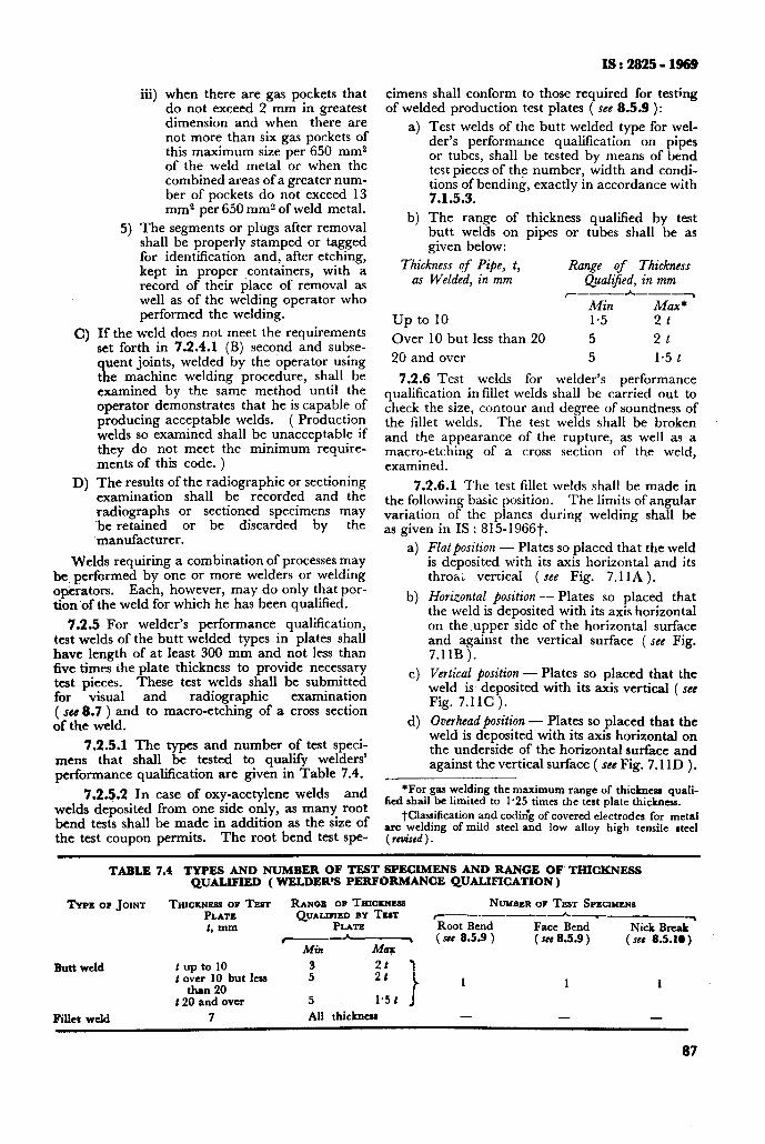
IS t 2825 - 1969
iii) when there are gas pockets that do not exceed 2 mm in greatest dimension and when there are not more than six gas pockets of this maximum size per 650 mm2 of the weld metal or when the combined areas of a greater num- ber of pockets do not exceed 13 mm2 per 650 mm? of weld metal.
5) The segments or plugs after removal shall be properly stamped or tagged for identification and, after etching, kept in proper containers, with a record of their place of removal as well as of the welding operator who performed the welding.
C) If the weld does not meet the reauirements &t forth in 7.2.4.1 (B) second and subse- quent joints, welded by the operator using the machine welding procedure, shall be examined by the same method until the operator demonstrates that he is capable of producing acceptable welds. ( Production welds so examined shall be unacceptable if they do not meet the minimum require- ments of this code. )
D> The results of the radiographic or sectioning examination shall be recorded and the radiographs or sectioned specimens may ‘be retained or be discarded by the manufacturer.
Welds requiring a combination of processes may be, performed by one or more welders or welding o@erators. Each, however, may do only that por- tion of the weld for which he has been qualified.
7.2.5 For welder’s performance qualification, test welds of the butt welded types in plates shall have length of at least 300 mm and not less than five times the plate thickness to provide necessary test pieces. These test welds shall be submitted for visual and radiographic examination ( see 8.7 ) and to macro-etching of a cross section of the weld.
7.2.5.1 The types and number of test speci- mens that shall be tested to qualify welders’ performance qualification are given in Table 7.4.
7.2.5.2 In case of oxy-acetylene welds and welds deposited from. one side only, as many root bend tests shall be made in addition as the size of the test coupon permits. The root bend test spec
cimens shall conform to those required for testing of welded production test plates ( see 8.5.9 ):
4
b)
Test welds of the butt welded type for wel- der’s performance qualification on pipes or tubes, shall be tested by means of bend test pieces of the number, width and condi- tions of bending, exactly in accordance with 7.1.5.3.
The range of thickness qualified by test butt welds on pipes or tubes shall be as given below:
Thickness of Pipe, t, Range of Thickness as Welded, in mm QualiJied, in mm
r----h--_~ Min Max*
up to 10 1.5 2t
Over 10 but less than 20 5 2t
20 and over 5 1.5 t
7.2.6 Test welds for welder’s performance qualification in fillet welds shall be carried out to check the size, contour and degree of soundness of the fillet welds. The test welds shall be broken and the appearance of the rupture, as well as a macro-etching of a cross section of the weld, examined.
7.2.6.1 The test fillet welds shall be made in the following basic position. The limits of angular variation of the planes during welding shall be as given in IS : 815-1966t.
4
b)
4
4
Flat position - Plates so placed that the weld is deposited with its axis horizontal and its thro& vertical (see Fig. 7.11A).
Horizontal position - Plates so placed that the weld is deposited with its axis horizontal on the upper side of the horizontal surface and against the vertical surface ( see Fig. 7.1 IB ).
Vertical bosition - Plates so nlaced that the 1
weld is, deposited with its a&s vertical ( see Fig. 7.11C ).
Overhead position - Plates so placed that the weld is deposited with its axis horizontal on the underside of the horizontal surface and against the vertical surface ( set Fig. 7.llD ).
*For gas welding the maximum range of thickness quali- fied shall be limited to 1.25 times the test plate thickness.
tClassification and codit?g of covered electrodes for metal arc welding of mild steel and low alloy high tensile steel ( reuised ) .
TABLE 7.4 TYPES AND NUMBER OF TEST SPECIMENS AND RANGE OF' THICKNESS QUALIFIED (WELDER'S PERF~RM.~NCE QU~~CATION)
TYPZOP JOINT THICKNESS OF TEST RANCW, OF THICKN~ILS NUMBER OF TB~T SPECIMENS PLATE QUALWIED BY TBIT r 1, mm PLATE Root Bend
^--__A_--_,
Face Bend Nick Break
--T (see 8.5.9 )
Min ( see 8.5.9 ) (see 8.5.10)
Butt weld t up to 10 3 1 t over 10 but LESS 5 2’:
than 20 1 1 1
t 20 and over 5 I.5 t
Fillet weld 7 All tbicknus - -
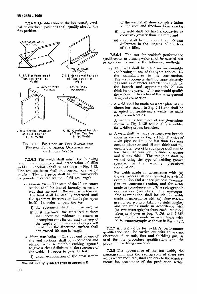
IS:2825-1969
7.2.6.2 Qualification in the horizontal, verli- cal or overhead positions shall qualify also for the flat position.
HORIZONTAL
7.1 IA Flat Position of 7.1 IB Horizontal Position Test Tee for Fillet of Test Tee Fillet
Weld Weld
c--,iXIS OF V’ELO I ,r AX’S OF WELD HORlZONTA!_
7.1 IC Vertical Position of Test Tee for
Fillet Weld
7.1 ID Overhead Position of Test Tee for
Fillet Weld
FIG. 7.11 POSITUONS OF TEST PLATES FOR WELDER PERFORMANCE Q~JALIFICATION
OF FILLET WELDS
7.2.6.3 The welds shall satisfy the following test. The dimensions and preparation of fillet weld test specimen shall be as shown in Fig. 7.12. The test specimen shall not contain any visible cracks. Thr test piece shall be cut transversely to provide a centrc section of 25 cm length:
a> F’ructure test - The stem of the 25-cm centre section shall be loaded laterally in such a way that the root of the weld is in tension. The load shall be steadily increased until the specimen fractures or bends flat upon itself. In order to pass the test:
i) the specimen shall not fracture; or
ii) if it fractures, the fractured surfaces shall show no evidence of cracks or incomplete root fusion, and the sum of the lengths of inclusions and gas pockets visible on the .fractured surface shall not exceed 50 mm in length.
b) Xucro-exnminntion - The cut end of one of the end sections shall be smoothened and etched with a suitable etching agents* to give a clear definition of the structure of :he weld. In order to pass the test:
i) visual examination of the cross section
*Suitable etching agents are given in Appendix K.
88
of the weld shall show complete fusim at the root and freedom from cracks;
ii) the weld shall not have a concavity or convexity greater than l-5 mm; and
iii) there shall be not more than l-5 mm difference in the lengths of the lee
of the fillet.
7.2.6.4 The test for welder’s performance qualification in branch welds shall be carried out to conform to one of the following methods:
4
b)
cl
The weld shall be made on an assembly conforming to one of the types adopted by the manufacturer in his construction. The test specimen shall be approximately 200 mm in diameter and 20 mm thick for the branch and approximately 20 mm thick for the plate. This test would qualify the welder for branches of this same general design of connection.
A weld shall be made on a test plate of the dimensions shown in Fig. 7.13 and shall be accepted for qualifying a welder to make set-in branch welds.
A weld on a test piece of the dimensions shown in Fig. 7.13B will qualify a welder for welding set-on branches.
A \\reld shall be made between two branch pipes as shown in Fig. 7.13C. The size of main pipe shall not be less than 127 mm outside diameter and 10 mm thick and the outside diameter of branch pipe shall not be less than 89 mm I on outside diameter and 6 mm thick. The test joint shall be welded usirg the type of welding groove specified m the welding procedure specification.
For welds made in accordance with (a) the test pieces shall be submitted to a visual examination and a macrographic examina- tion on transverse section, and for welds made in accordance with (b) a radiographic examination ( scc 8.7 ). The macrogra- phic examination shall include, for welds made in accordance with (a), four macro- graphs on sections taken at right angles; and for welds made in accordance with (b) two macrogl’aphs from each test piece taken as shown in Fig. 7.13A and 7.13B and for welds made in accordance with (c) fourmacrographs as shown in Fig. 7.13C.
7.2.7 All test welds for welder’s performance qualification shall be carried out with equivalent electrodes, filler rods, flux and shielding gas, ,a used for the procedure qualification and the production welding concerned.
7.2.8 The appearance of the test welds, the macrographs, and the radiographs of these test welds where required, shall conform to the require- ments for, acceptance of the production welds,
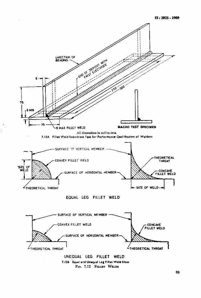
’
c
MACRO TI
-.
/
All dimensions in millimctreh
7.I2A Fillot Weld Soundness Test for Performance Qualification of Welders
SURFACE ?C YERT!CAL KEMEEF!
THEORETICAL CONVEX FILLET WELD
SURFACE OF HCRltONiAL MEMBER
THEORETICAL THROAT SIZE OF WELD
EQUAL LEG FILLET WELD
- SURFACE OF VERTICAL MEMBER
CONVEX FILLET WELD
SURFACE OF HORIZONTAL MEMBER
I THEORETICAL THROAT
UNEQUAL LEG FILLET WELD 7.126 Equal and Unequal Leg Flllct Weld Sizes
FIO. 7.12 FILLET WELDS
89
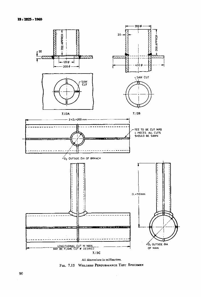
13r!B!i?!i-1969
I----2OP~--l
\SAW CUT \ +cll _-+__
I I
7.I3A 7.136
/-TEE TO BE CUT INTO 4 PIECES ALL CUTS s~ouL0 BE SAWN
O2 OUTSIDE OIA OF BRANCH I
90
LONGITUDINAL CUT IN MAIN MAY BE FLAME CUT IF DESIRED
r’o, OUTSIDE .OIA
OF MAIN
7.13c
All dimensions in millimetres.
FIG. 7.13 WELDERS PERFORMANCE TEST SPECIMEN
7.2.8.1 Retests - A welder who fails to .meet the requirements for one or more of the test speci-
* mens prescribed in Table 7.4 may be tested under the following conditions:
a) When an immediate retest is made, the welder shall make two test welds of each type for each position on which he has failed, all of which shall pass the test requirements.
b) When the welder has had further training or practice, a complete retest shall be made for each position on which he failed to meet the requirements.
7.2.9 Requalification of welder’s performance will have to take place in case of requalification of the welding procedure due to a substantial change in essential variables as listed in 7.1.3.
7.2.9.1 Essential variables - A welder shall be requalified whenever one or more of the changes listed below are made in the performance specification:
4
b)
4
4
4
f 1
8)
The addition of other welding positions than those already qualified under 7.2.6.1.
The omission of backing strip in metal-arc welding single welded butt joints.
The addition of backing strip in gas welding.
A change from one welding process to any other welding process or a combination of welding processes.
Where a combination of welding processes is required to make a weldment, each wel- der or welding operator shall be qualified for the particular welding process he is required to perform in production welding.
A change from any non-consumable process to any consumable-electrode process or rice versa.
Where combination welds are used, the
h) In any welding process, the omission or addition of consumable backing rings or strip.
3 The omission of inert gas backing.
r!3:282!i-l!w9
welder or welding operator who is to make the root pass shall be tested only by means of a minimum of two root bends instead of the face bends and side bends listed in Table 7.4.
7.2.10 A welder having carried out a welding procedure qualification with good results will also be qualified for welder’s competence in the pro- cedure concerned, except in the case of branch welds.
7.2.10.1 Welder who passes the tests for butt welds shall also be qualified to make fillet welds in all thicknesses. Welder who passes the tests for fillet welds shall be qualified to make filiet welds only.
7.2.10.2 Renewal of qualijication - Renewal of qualification of a performance qualification is required (a) when a welder or welding operator has not used the specific process, that is, metal arc, gas, submerged arc, etc, to weld either ferrous or non-ferrous materials for a period of six months or more, or (b) when there is a specific reason to question his ability to make welds that meet the specification. Renewal of qualification under (a) need be made in only a single test-plate thickness.
7.2.11 Records of all tests shall be kept by the manufacturer and shall be available for the inspect- ing authority for examination whenever required. Suggested form for the records is given in Appendix H.
7.2.11.1 ‘Each qualified welder and welding operator shall be assigned one identifying number, letter or symbol by the manufacturer which shall be used to identify the work of that welder or welding operator.
91

As in the Original Standard, this Page is Intentionally Left Blank
SECTION III INSPECTION, TESTS, MARKiNG AND RECORDS
8. INSPECTION AND TESTS
8.1 General
8.2 Inspection During Manufacture
8.3 Inspection of Completed Pressure Vessels
8.4 Pressure Tests
8.5 Mechanical Tests of Fusion Welded Seams - Production Test Plates
8.6 Requirements for Test Results of Welded Production Test Plates
8.7 Non-destructive Examination and Repairs of Welded Seams
9. MARKING AND RECORDS
9.1 Marking
9.2 Certificate of Manufacture and Test
. . . 95
. . . 95
. . . 95
. . . 95
. . . 95
I... 96
. . . 102
. . . 103
. . . 110
. . . 110
. . . 111
8. INSPECTION AND TESTS
8.1 General - Inspection shall be made at the various stages of construction depending on the classification of the vessel ( see Table 1.1 ). The manufacturer shall keep the purchaser and/or the inspecting authority informed of the progress of the work and shall notify the inspector reason- ably in advance when the vessel has reached the required stage for inspection.
8.2 Inspection During Manufacture - All materials to be used for pressure parts of vessels shall be inspected before fabrication for the purpose of detecting defects which may affect the safety of the vessel.
8.2.1 Special attention shall be paid to the cut edges and other parts of rolled material which may disclose the existence of serious lamina- tions, shearing cracks and other objectionable defects.
8.2.1.1 Defects shall not be repaired unless ins- pected and approved by the inspecting authority. Material which, in the inspecting authority’s . . cannot be satisfactorily repaired shall be zFg?not to comply with the requirements of this code.
8.2.2 JdentiJication of Materials - The inspector shall ensure that all material before use is properly identified as complying with the code requirements. Mill certificates or other test certificates to the satisfaction of the inspecting authority shall be produced to identify the material, The manufacturer’s identification marks should not be obliterated during manufacture. Where necessary the marks shall be transferred in the presence of the inspector. Steel plate less than 7 mm thick or non-ferrous plate less than 12 mm thick shall not be deep die stamped and the depth of stamping shall not exceed 0.5 mm.
8.2.2.1 ‘The inspector shall witness the mark- ing of, and place his own stamp on portions of the parent plate intended to be used as test plates for seams. The mark should be so located that it will not be cut out or obliterated during fabrication.
8.2.3 Inspection During Fabrication
8.2.3.1 The inspector shall make inspections of each vessel at such stages of fabrication as he deems necessary to assure himself that the fabrica- tion is according to code requirements.
6.2.3.2 The edges of plates, openings and fittings exposed during manufacture shall be examined for defects.
8.2.3.3 Before assembly, all. shell sections, ends, rings, etc, shall be examined for conformity to prescribed shape and checked for thickness and dimensions.
8.2.3.4 The component parts of the vessel shall be assembled and checked for alignment of
ISr2823-1969
matching edges. Special attention shall be paid to assembly of branches and to their reinforcement.
8.2.3.5 When conditions permit entry into the vessel, as complete an examination as possible shall be made before the final closure.
8.2.4 Heat Treatment Check-The inspector shall satisfy himself that stress-relieving prpcedure or other heat treatment, as may be necessary, has been correctly carried out.
8.3 Inspection of Completed Pressure Vessels
8.3.1 Visual Znsfiection - During the final ins- pection of the whole vessel the surfaces of the welds are to be inspected visually and judged as stated under 6.7.15.
If irregularities are found, rectification shall be carried out ( see 6.9 ).
8.3.1.1 Records of manufacturing details, inspection and tests shall be kept by the manufac- turer and shall be available for the inspecting authority for examination, whenever required. Manufacturer shall furnish a certificate of manu- facture and production tests when requested in the form given in Appendix M.
8.3.2 Radiographic Examination - Radiographic examination of welded joints shall be carried out in the instances where required following the rules specified under 8.7. Where so required by the inspecting authority the results of the radiographic examinahon shall be made available to him at the manufacturer’s works.
8.3.2.1 All austenitic chromium nickel alloy steel welds in vessels whose shell thickness exceeds 20 mm, shall be examined for cracks by a suitable fluid penetration method.
8.4 Pressure Tests
8.4.1 The finished vessel shall, in the presence of the inspecting authority, pass satisfactorily such of the following pressure tests as may apply:
4
W
4
Standard hydrostatic test - for simple vessels where thickness of all pressure parts can be calculated.
Proof hydrostatic tests - for complex vessels the thickness of which cannot be computed with a satisfactory assurance of accuracy and for which the maximum working pres- sure has to be based upon the distortion pressure.
Pneutiatic tests - for vessels so designed and/ or_ supported that they cannot be safsly filled with the testing liquid or for- ves$s that are to be used in services where even small traces of the testing liquid cannot be tolerated.
8.4.2 Pressure vessels in’mild or low-alloy steels designed for internal pressure, shall be subjected to a hydraulic test pressure, which at every point
95
Is: 2825 -1969
in the vessel is at least equal to l-3 times the design pressure to be marked on the vessel multiplied by the lowest ratio of the allowable stress valuef, of the material of construction at the test temperature to the allowable stress value fa at the design temperature.
Test pressure in kgf/cms = l-3 x design f, at test temperature
pressure ‘fi at design temperature
8.4.2.1 The test pressure specified in 8.4.2 includes the amount of any static head acting at the point under consideration. If the weakest part of the vessel is not located at the lowest point of the vessel, it may be necessary to give special considera- tion to the effect of such additional static head due to the test liquid.
8.4.2.2 Vessels consisting of more than one independent pregsure chamber operating at the same or different pressures and temperatures shall be so rested that each pressure chamber ( vessel ) receives the required hydraulic test with pressure in the others.
NOTE - It is important in the interest of safety that the vessel be properly vented so as to prevent formation of air pockets before the test pressure is applied. It is recommended that during the test the temperature of the water should not be below 15°C.
A hydraulic test based on a calculated pressure may be used by agreement between the purchaser and the manufacturer.
The vessel shall be maintained at the specified test pressure for a sufficient length of time to -it a thorough examination to be made of all’searns and joints but in no case less than 10 minutes. Whilst under pressure, the vessel to be well ham- mered on both sides of and close to the welded seams.. Hammer test is not required for vessels fabricated from materials which will be delete- riously affected by hammering and where the longitudinal and circumferential seams have been radiographed.
Single wall vessels and chambers of multi- chamber vessels designed for vacuum or partial vacuum only shall be subject to an internal hydrau- lic test pressure not less than l-3 times the difference between normal atmospheric pressure and the minimum design internal absolute pressure, but in no case less than l-5 kgf/cmr. In case of jacketed vessels when the inner vessel is designed to operate at atmospheric pressure or under vacuum conditions, the test pressure need only be applied to the jacket space [ see also 3.12.1(c) 1.
8.4.3 Pneumatic Tests
8.4.3.1 Pressure testing with air or gas may be carried out in lieu of the standard hydraulic test in the following cases:
a) Vessels that are so designed, constructed or supported that they cannot safely be filled with water or liquid;
b) Vessels that are to be used in services where
96
even small traces of water cannot be tolerated.
Such pneumatic pressure test shall be carried out under close supervision by the inspecting authority. Adequate precautions, such as blast walls or pits and means ‘for remote observation are essential.
8.4.3.2 The pneumatic test pressure shall not be less than the design pressure but need not exceed test pressure in a hydraulic test.
8.4.3.3 Procedure -The pressure shall gradu- ally be increased to not more than 50 percent of the test pressure. Thereafter the pressure shall be increased in steps ofapproximately 10 percent of the test pressure till the required test pressure is reached. Then the pressure shall be reduced to the value of the equivalent design pressure and held at the pressure for a sufficient time to permit inspection of the vessel.
8.4.4 Combined Hydrostatic Pneumatic Test
8.4.4.1 In some cases it may be desirable to pneumatically test a vessel partially filled with liquid. In such cases a pneumatic test may be applied to the space above the liquid level, the pneumatic test pressure being as required in 8.4.3.2 less the pressure due to the static head of the liquid contained.
8.4.4.2 When pressure testing small, mass- produced pressure vessels, the length of time for which the test pressure is to be maintained may be reduced upon agreement with th{ inspecting authority in each individual case.
8.5 Mechanical Tests of Fusion Welded Seams - Production Test Plates
8.5.0 Fusion welded seams shall satisfy the following mechanical tests.
8.&l Vessels subjected to severe duty or with a weld joint efficiency factor J = 0.9 to 1.0 shall be provided with two test plates to represent the welding of all the longitudinal seams of the first six shells or part thereof. Vessels with more than six shells shall have a test plate for every third additional shell or part thereof. No test plate need be provided for circumferential seams except in cases where a pressure vessel has circuml ferential seams only or if the welding process, procedure and technique is different in which case two test plates are to be provided, each having a joint as far as possible a duplication of the circumferential seam.
8.5.1.1 Test plates shall be attached at one end of the longitudinal seam in such a manner that the edges to be welded are a continuation and duplication of the corresponding edges of the seam. Welding shall be effected in one reasonably con- tinuous operation by the same process and the operator or operators. Location of test plates shall be as agreed to between the inspecting authority and the manufacturer.
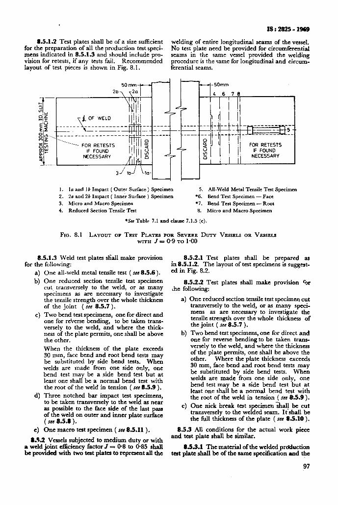
. IS:2825-1969
8.5.1.2 Test plates shall be of a size sufficient for the preparation of all the production test speci-
welding of entire longitudinal seams of the vessel.
mens indicated in 8.5.1.3 and should include pro- No test plate need be provided for circumferential
vision for retests, if any tests fail. Recommended seams in the same vessel provided the welding
layout of test pieces is shown in Fig. 8.1. procedure is the same for longitudinal and circum- ferential seams.
+-4-50mm
4 6 70
________ _--
1 FOR RETESTS
NECESSARV
r *
1. la and 1 b Impact ( Outer Surface ) Specimen 5. All-Weld Metal Tensile Test Specimen
2. 2a and 26 Impact ( Inn& Surface ) Specimen *6. Bend Test Specimen - Face 3. Micro and Macro Specimen ‘7. Bend Test Specimen -Root
4. Reduced Section Tensile Test 8. Micro and Macro Specimen
*See Table 7.1 and clause 7.1.5 (c).
FIG. 8.1 LAYOUT OF TEST PLATES FOR SEVERE DUTY VESSELS OR Vessms WITH .f = 0.9 TO 1 *oo
8.5.1.3 Weld test plates shall make provision for the following:
a> b)
4
4
4
One all-weld metal tensile test ( see 8.5.6 ),
One reduced section tensile test specimen cut transversely to the weld, or as many specimens as are necessary to investigate the tensile strength over the whole thickness of the joint ( see 8.5.7 ).
Two bend test specimens, one for direct and one for reverse bending, to be taken trans- versely to the weld, and where the thick- ness of the plate permits, one shall be above the other.
When the thickness of the plate exceeds 30 mm, face bend and root bend tests may be substituted by side bend tests. When welds are made from one side only, one bend test may be a side bend test but at least one shall be a normal bend test with the root of the weld in tension ( see 8.5.9 ).
Three notched bar impact test specimens, to be taken transversely to the weld as near as possible to the face side of the last pass of the weld on outer and inner plate surface ( see 8.5.8 ).
One macro test specimen ( see 8.5.11 ).
8S.2 Vessels subjected to medium duty or with a weld joint efffciency factor J = @8 to @85 shall be provided with two test plates to represent all the
8.5.2.1 Test plates shall be prepared as in 8.5.1.2. The layout of test specimens is suggest- ed in Fig. 8.2.
8.5.2.2 Test plates shall make provision %r ihe following:
4
b)
c>
One reduced section tensile test specimen cut transversely to the weld, or as many speci- mens as are necessary to investigate the tensile strength over the whole thickness of the joint ( see 8.5.7 ).
Two bend test specimens, one for direct and one for reverse bending to be taken trans- versely to the weld, and where the thickness of the plate permits, one shall be above the other. Where the plate thickness exceeds 30 mm, face bend and root bend tests may be substituted by side bend tests. When welds are made from one side only, one bend test may be a side bend test but at least one shall be a normal bend test with the root of the weld in tension ( see &!I.9 ).
One nick break test specimen &all be cut transversely to the welded seam. It shall be the full thickness of the plate ( see 85.10 ).
8.5.3 All conditions for the actual work piece and test plate shall be similar.
8.5.3.1 The material of the welded production test plate shall be of the same specScation and the
97
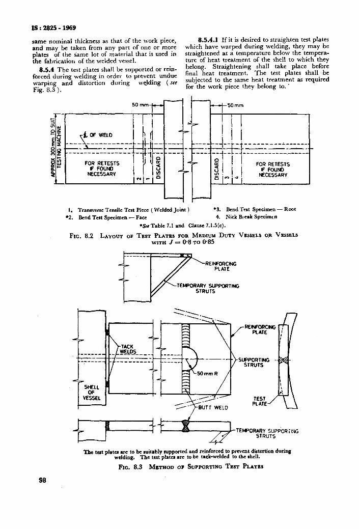
IS:2825-1969
same nominal thickness as that of the work piece, 8.5.4.1 If it is desired to straighten test plates
and may be taken from any part of one or more which have warped during welding, they may be plates of the same lot of material that is used in straightened at a temperature below the tempera- the fabrication of the welded vessel. ture of heat treatment of the shell to which they
8.5.4 The test plates shall be supported or rein- belong. Straightening shall take place before
forced during welding in order to prevent undue fina1 heat treatment* The test plates shall ‘be
warping and distortion during welding ( see subjected to the same heat treatment as required
Fig. 8.3 ). for the work piece they belong to. .
--50 mm
FOR RETESTS
1. Transverse Tensile Test Piece ( Welded Joint ) l 3, Bend Test Specimen - Root
l 2. Bend Test Specimen - Face 4. Nick Bleak Specimen
*Set Table 7.1 and Clause 7.1.5(c).
FIG. 8.2 LAYOUT OF TEST PLATES F~~~IX;IJ; DUTY VG~SELS O.R VESSELS WITHJ= ’ *
RE’Y3:w
w@ol?ARv SuPPofmNG STRUTS
‘I&e tat plater are to be suitably rupported and reinforced to prevent dirtortion during welding. The test plates are to be tack-welded to the shell.
FIG. 8.3 METHOD OF SUPPORTING TEST PLATES
98
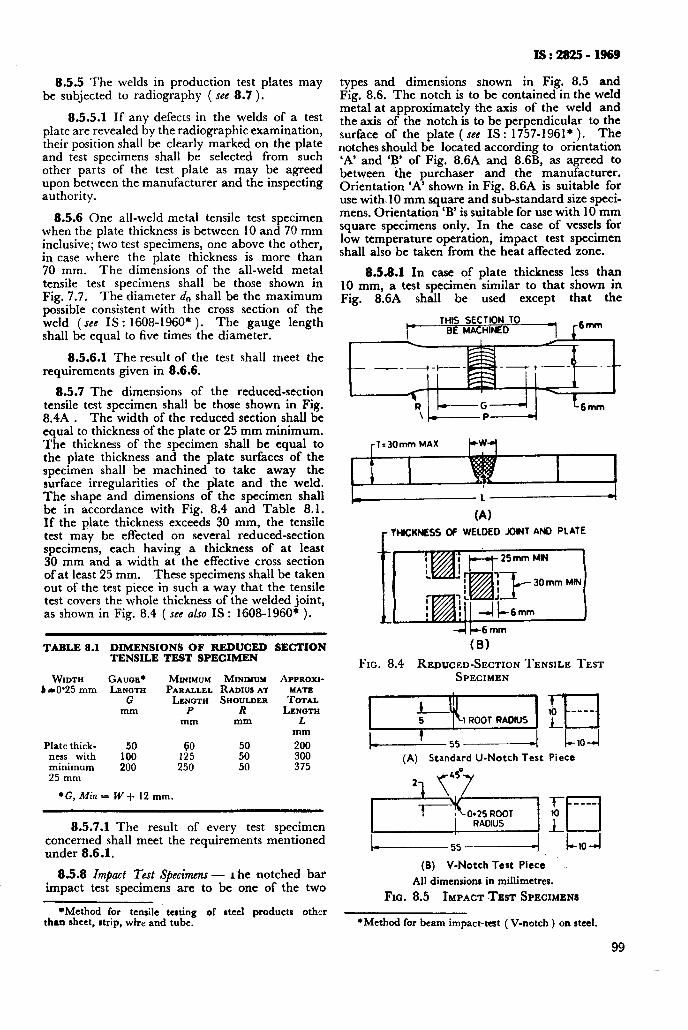
8.5.5 The welds in production test plates may be subjected to radiography ( see 8.7 ).
8.5.5.1 If any defects in the welds of a test plate are revealed by the radiographic examination, their position shall be clearly marked on the plate and test specimens shall be selected from such other parts of the test plate as may be agreed upon between the manufacturer and the inspecting authority.
8.5.6 One all-weld metal tensile test specimen when the plate thickness is between 10 and 70 mm inclusive; two test specimens, one above the other, in case where the plate thickness is more than 70 mm. The dimensions of the all-weld metal tensile test specimens shall be those shown in Fig. 7.7. The diameter d,-, shall be the maximum possible consistent with the cross section of the weld ( see IS : 160%1960* ). The gauge length shall be equal to five times the diameter.
8.5.6.1 The result of the test shall meet the requirements given in 8.6.6.
8.5.7 The dimensions of the reduced-section tensile test specimen shall be those shown in Fig. 8.4A . The width of the reduced section shall be equal to thickness of the plate or 25 mm minimum. The thickness of the specimen shall be equal to the plate thickness and the plate surfaces of the specimen shall be machined to take away the surface irregularities of the plate and the weld. The shape and dimensions of the specimen shall be in accordance with Fig. 8.4 and Table 8.1. If the plate thickness exceeds 30 mm, the tensile test may be effected on several reduced-section specimens, each having a thickness of at least 30 mm and a width at the effective cross section of at least 25 mm. These specimens shall be taken out of the test piece in such a way that the tensile test covers the whole thickness of the welded joint, as shown in Fig. 8.4 ( see also IS : 16081960* ).
TABLE 8.1 DIMENSIONS OF REDUCED SECTION TENSILE TEST SPECIMEN
WIDTH Gauoe' MZNIMUM bhO.25 mm LENT PARALLEL
LENGTH mm P
mm
Plate thick- 60 ness with 125 minimum 200 250 25 mm
+G, Min = W+ 12 mm.
MINIMUM APPROXI- RADIUS AT MATE SHOULDER TOTAL
R LENGTH mm L
mm
5”8 200 300
50 375
8.5.7.1 The result of every test specimen concerned shall meet the requirements mentioned under 8.6.1.
8.5.8 Impact Test S’ecimens - he notched bar impact test specimens are to be one of the two
*Method for tensile testing of steel products other than sheet, atrip, wfre and tube.
types and dimensions shown in Fig. 8.5 and Fig. 8.6. The notch is to be contained in the weld metal at approximately the axis of the weld and the axis of the notch is to be perpendicular to the surface of the plate (see IS : 1757-1961* ). The notches should be located according to orientation ‘A’ and ‘B’ of Fig. 8.6A and 8.6B, as agreed to between the purchaser and the manufacturer. Orientation ‘A’ shown in Fig. 8.6A is suitable for use with. 10 mm square and sub-standard size speci- mens. Orientation ‘B’ is suitable for use with 10 mm square specimens only. In the case of vessels for low temperature operation, impact test specimen shall also be taken from the heat affected zone.
8.5.8.1 In case of plate thickness less than 10 mm, a test specimen similar to that shown in Fig. 8.6A shall be used except that the
\I.99P-----cl
rT=30mm MAX WV
I--L -I
(A)
r THICKNESS OF WELDED JOINT AN0 PLATE
--i!-6mm
(B) FIG. 8.4 REDUCED-SECTION TENSILE TEST
%‘EClMEN
IF]%]
(A) Standard U-Notch Test Piece
l------55_1 I404
(B) V-Notch Test Piece
All dimensions in millimetres.
FIG. 8.5 IMPACT TEST SPECIMENS
*Method for beam impact-test ( V-notch ) on steel.
99
-._
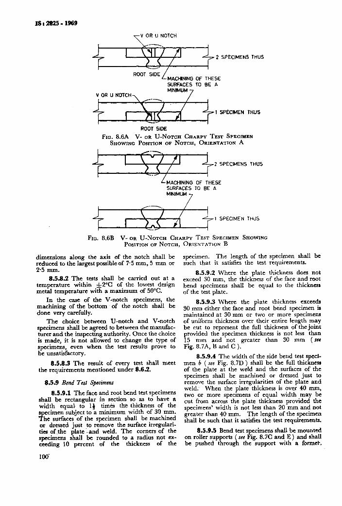
IS:292!i-1969
V OR U NOTCH
--.
I \YI / /‘I 2 SPECIMENS THUS
l--’
ROOT SlCJ~L MACHINING OF THESE SURFACES TO BE A MINIMUM
VORUNOTCHY 7
ROOT SIDE
FIG. 8.6A V- OR U-NOTCH CHARPY TEST SPECIMEN SHOWING POSITION OF NOTCH, ORIENTATION A
/--,
I \‘/ fl 2 SPECiMENS THUS
LMACHINING OF THESE SURFACES TO BE A
+++I SPECIMEN THUS
FIG. 8.6B V- OR U-NOTCH CHARPY TEST SPECIMEN SHOWING POSITION OF NOTCH, ORIENTATION B
dimensions along the axis of the notch shall be reduced to the largest possible of 7.5 mm, 5 mm or 2.5 mm.
8.5.8.2 The tests shall be carried out at a temperature within -J=2”C of the lowest design metal temperature with a maximum of 50°C.
In the case of the V-notch specimens, the machining of the bottom of the notch shall be done very carefully.
The choice between U:notch and V-notch specimens shall be agreed to between the manufac- turer and the inspecting authority. Once the choice is made, it is not allowed to change the type of specimens, even when the test results prove to be unsatisfactory.
8.5.8.8 The result of every test shall meet the requirements mentioned under 8.6.2.
8.5.9 Bend Tesi Sptcimcnr
8.5.9.1 The face and root bend test specimens shall be rectangular in section so as to have a width equal to 1) times the thickness of the specimen subject to a minimum width of 30 mm. The surfaces of the specimen shall be machined or dressed just to remove the surface irregulari- ties of.the plate -and weld, The corners of the specimens shall be rounded to a radius not ex- ceeding 10 percent of the thickness of the
specimen. The length of the specimen shall be such that it satisfies the test requirements.
8.5.9.2 Where the plate thickness does not exceed 30 mm, the thickness of the face and root bend specimens shall be equal to the thickness of the test plate.
8.5.9.3 Where the plate thickness exceedr 30 mm either the face and root bend specimen is maintained at 30 mm or two or more specimens of uniform thickness over their entire length may be cut to represent the full thickness of the joint provided the specimen thickness is not less than 15 mm and not greater than 30 mm ( see Fig. 8.7A, B and C ).
8.5.9.4 The width of the side bend test sped- men b ( see Fig. 8.7D ) shall be the full thickness of the plate at the weld and the surfaces of the specimen shall be machined or dressed just to remove the surface irregularities of the plate and weld. When the plate thickness is over 40 mm, two or more specimens of equal width may be cut from across the plate thickness provided the specimens’ width is not less than 20 mm and not greater than 40 mm. The length of the specimen shall be such that it satisfies the test requirements.
8.5.9.5 Bend test specimens shall be mounted on roller supports ( see Fig. 8.7C and E ) and shall be pushed through the support with a former.
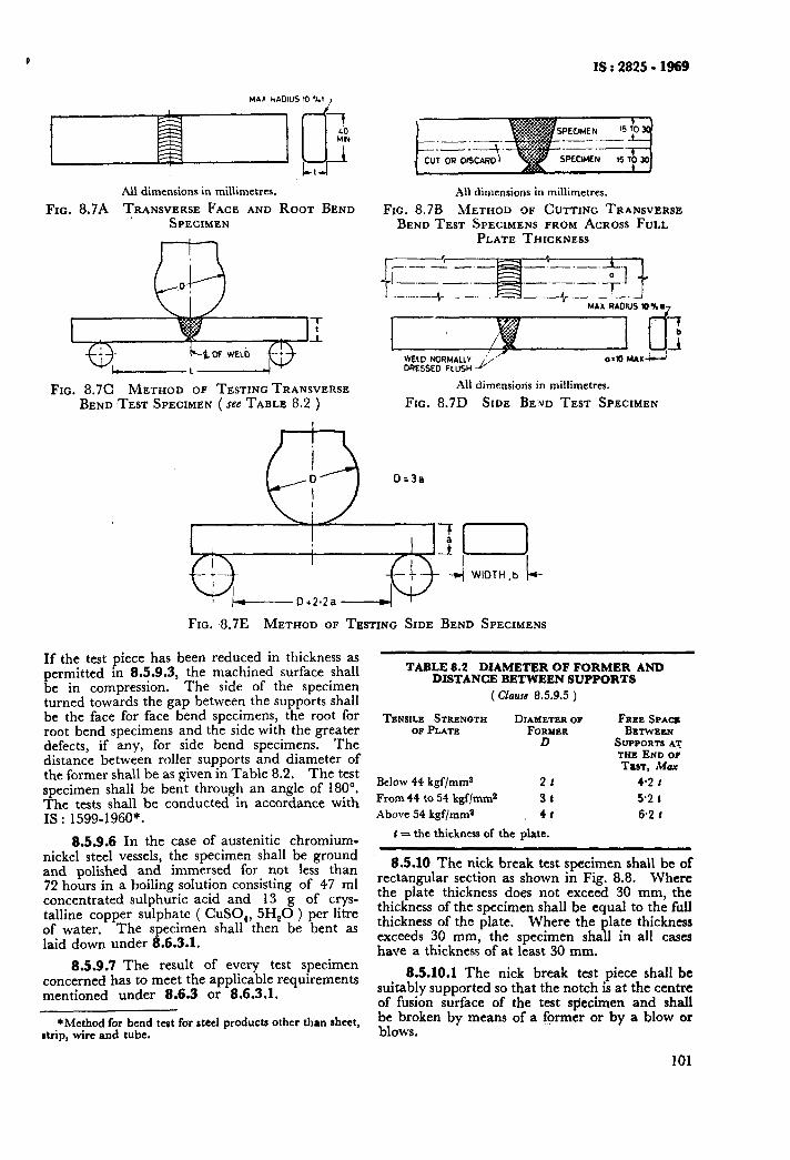
IS : 2825 - 1969
All dimensions in miliimetres.
FIG. 8.7A TRANSVERSE FACE AND ROOT BEND SPECIMEN
$10. 8.7C METHOD OF TESTING TRANSVERSE BEND TEST SPECIMEN ( see TABLE 8.2 )
AlI dimensions in millimetres.
FIG. 8.7B METHOD OF CUTTING TRANSVERSE BEND TEST SPECIMENS FROM ACROSS FULL
PLATE THICKNESS
-.--_- - -._.
--I -.- - +,I L._ ._.--+- __- ‘- -,-- -I-’
I MAX RADIUS 10X0-,
WELD NORMALLY &’ OQESSE 0 FLUSH
All dimensions in millimetres.
FIG. 8.7D SIDE BEND TEST SPECIMEN
0=3a
FIG. 8.7E METHOD OF TESTING SIDE BEND SPECIMENS
If the test piece has been reduced in thickness as permitted in 8.5.9.3, the machined surface shall be in compression. The side of the specimen turned towards the gap between the supports shall be the face for face bend specimens, the root for root bend specimens and the side with the greater defects, if any, for side bend specimens. The distance between roller supports and diameter of the former shall be as given in Table 8.2. The test specimen shall be bent through an angle of 180”. The tests shall be conducted in accordance with IS : 1599-1960*.
8.5.9.6 In the case of austenitic chromium- nickel steel vessels, the specimen shall be ground and polished and immersed for not less than 72 hours in a boiling solution consisting of 47 ml concentrated sulphuric acid and 13 g of crys- talline copper sulphate ( CuSO,, 5H,O ) per litre of water. The specimen shall then be bent as laid down under 8.6.3.1.
8.5.9.7 The result of every test specimen concerned has to meet the applicable requirements mentioned under 8.6.3 or 8.6.3.1.
*Method for bend test far steel products other than sheet, drip, wire and tube.
TABLE 8.2 DIAMETFR OF FORMER AND DISTANCE BETWEEN SUPPORTS
( Clam 8.5.9.5 )
TENSILE STRENGTH DIAMETER OF OP PLATE FORMER
D
Below 44 kgf/mm2 21
From 44 to 54 kgf/mm2 3r
Above 54 kgf/mma 41
1 = the thickness of the plate.
FREE SPACZ BRTWEEN
SUPPORTSA'J THE END OF TEST, Max
4.2 t 5.2 1
6-2 t
8.5.10 The nick break test specimen shall be of rectangular section as shown in Fig. 8.8. Where the plate thickness does not exceed 30 mm, the thickness of the specimen shall be equal to the full thickness of the plate. Where the plate thickness exceeds 30 mm, the specimen shall in all caies have a thickness of at least 30 mm.
8.5.10.1 The nick break test piece shall be suitably supported so that the notch is at the centre of fusion surface of the test stiecimen and shall be broken by means of a former or by a blow or blows.
101
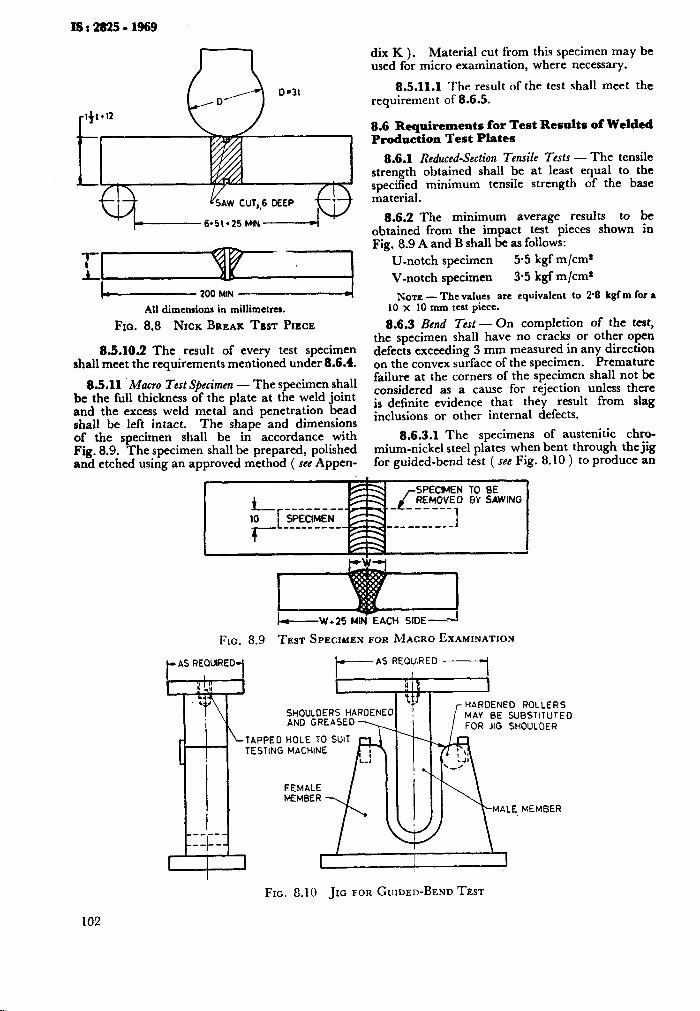
I---------_- 200 MIN
All dimensions in millimetrcs.
FIO. 8.8 NICK BREAK TEST PIECE
83.105 The result of every test specimen shall meet the requirements mentioned under 8.6.4.
8.5.11 ‘Macro Test Specimen - The specimen shall be the full thickness of the plate at the weld joint and the excess weld metal and penetration bead shall be left intact. The shape and dimensions of the specimen shall be in accordance with Fig. 8.9. The specimen shall be prepared, polished and etched using an approved method ( see Appen-
dix K ). Material cut from this specimen may be used for micro examination, where necessary.
8.5.11.1 The result of the test shall meet the requirement of 8.6.5.
8.6 Requirements for Test Results of Welded Production Test Plates
8.6.1 Reduced-Section Tensile Tests - The tensile strength obtained shall be at least equal to the specified minimum tensile strength of the base material.
8.62 The minimum average results to be obtained from the impact test pieces shown in Fig. 8.9 A and B shall be as follows:
U-notch specimen 5.5 kgf m/cm* V-notch specimen 3.5 kgf m/cm*
NOTE - Thevalues are equivalent to 2.8 kgf m for a 10 x 10 mm teat piece.
8.6.3 Bend Test - On completion of the test, the specimen shall have no cracks or other open defects exceeding 3 mm measured in any direction on the convex surface of the specimen. Premature failure at the corners of the specimen shall not be considered as a cause for rejection unless there is definite evidence that they result from slag inclusions or other internal defects.
8.6.3.1 The specimens of austenitic chro- mium-nickel steel plates when bent through the jig for guided-bend test ( see Fig. 8.10 ) to produce an
TO BE BY SAWING
I-W + 25 MINr EACH SIDE--‘I
FIG. 8.9 TEST SPECIMEN FOR MACRO EXAMINATION
f-AS REQUIRED.j *AS REQUIRED ------_I
r
LTAPPED HOLE TO SUIT TESTING MACHINE
FEMALE MEMBER
FIG. 6.10 JIG FOR GUIDED-BEND TEST
102
MEMBER
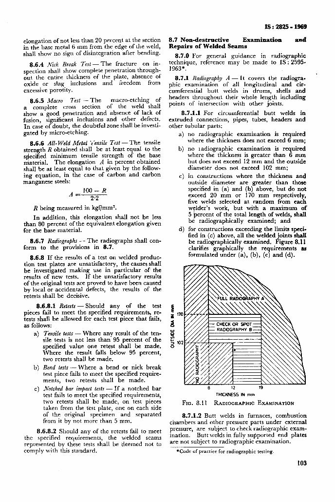
IS : 2825 ; 1969
8.7 Non-destructive Examination and Repairs of Welded Seams
8.7.0 For general guidance in radiographic technique, reference may be made to IS : 2595- 1963*.
8.7.1 Radiography A - It covers the radiogra- phic examination of all longitudinal and cir- cumferential butt welds in drums, shells and headers throughout their whole length including points of intersection with other joints.
elongation of not less than 20 percent at the section in the base metal 6 mm from the edge of the weld, shall show no sign of disintegration after bending.
8.6.4 jVick Break Test-The fracture on in- spection shall h s ow complete penetration through- out the entire thickness of the plate, absence of oxide or slag inclusions and freedom from excessive porosity.
8.6.5 Macro Test - The macro-etching of a complete cross section of the weld shall show a good penetration and absence of lack of fusion, significant inclusions and other defects. In case of doubt, the doubtful zone shall be investi- gated by micro-etching.
8.6.6 All- Weld Metal iensile Test - The tensile strength R obtained shall be at least equal to the s ecified n!
minimum tensile strength of the base aterial. The elongation A in percent obtained
shall be at least equal to that given by the follow- ing equation, in the case of carbon and carbon manganese steels:
A IOO- R
= 2.2
R being measured in kgf/mms.
In addition, this elongation shall not be less than 80 percent of the equivalent elongation given for the base material.
8.6.7 Radiographs - The radiographs shall con- form to the provisions in 8.7.
8.6.8 If the results of a test on welded produc- tion test plates are unsatisfactory, the causes shall be investigated making use in particular of the results of new tests. If the unsatisfactory results of the original tests are proved to have been caused by local or accidental defects, the results of the retests shall be decisive.
8.6.8.1 Retests-Should any of the test pieces fail to meet the specified requirements, re- tests shall be allowed for each test piece that fails, as follows:
4
b)
c)
Tensile tests - Where any result of the ten- sile tests is not less than 95 percent of the specified value one retest shall be made. Where the result falls below 95 percent, two retests shall be made.
Bend tests - Where a bend or nick break test piece fails to meet the specified require- ments, two retests shall be made.
Notched bar impact tests - If a notched bar test fails to meet the specified requirements, two retests shall be made, on test pieces taken from the test plate, one on each side of the original specimen and separated from it by not more than 5 mm.
8.6.8.2 Should any of the retests fail to meet the specified requirements, the welded seams represented by these tests shall be deemed not to comply with this standard.
8.7.1.1 For circumferential butt welds in extruded connections, pipes, tubes, headers and other tubular parts:
4
b)
c)
4
no radiographic examination is required where the thickness does not exceed 6 mm;
no 1 adiographic examination is required where the thickness is greater than 6 mm but does not exceed 12 mm and the outside diameter does not exceed 102 mm;
in constructions where the thickness and outside diameter are greater than those specified in (a) and (b) above, but do not exceed 20 mm or 170 mm respectively, five welds selected at random from each welder’s work, but with a maximum of 5 percent of the total length of welds, shall be radiographically examined; and
for constructions exceeding the limits speci- fied in (c) above, all the welded joints shall be radiographically examined. Figure 8.11 clarifies graphically the requirements aa formulated under (a), (b), (c) and (d).
6 12 19
THICKNESS IN mm
FIG. 8.11 RADIOGRAPHIC EXAMINATION
8.7.1.2 Butt welds in furnaces, combustion chambers and other pressure parts under external pressure, are subject to check radiographic exam- ination. Butt welds in fully sufiported end plates are not subject to radiographic examination.
*Code of practice for radiographic testing.
103
IS : 2825 - 1969
8.7.2 Radiography B - Spot or check radiogra- phic examination of the welded joints in question, comprising at least 10 percent of their whole length. The individual radiographs should not be shorter than 25 cm unless this is necessitated by the shape of the joints, the radiographic examination shall in all cases comprise all points of intersection with other joints, unless these points have already been examined by the radiographic examination of the other joints. At least one radiograph for the work of each welder or welding operator used in the fabrication of the vessel is necessary.
8.7.2.1 If the results of the examination of check radiographs of the selected welds are not satisfactory, the cause shall be investigated and, if considered necessary, the percentage of radio- graphic inspection increased by agreement between the manufacturer and the inspecting authority.
8.7.3 Preparation of Wt$ds for Radiographic Examination - All butt welded joints to be radio- graphed shall be free from weld ripples or weld surface irregularities on both the inside and the outside, to a ‘degree such that the resulting radio- graphic contrast due to any remaining irregularities cannot be confused with that of any objectionable defects. Also the weld surface shall merge smooth- Iy into the plate surface.
8.7.3.1 The finished surface of reinforcement may be flush or have a reasonably uniform crown not exceeding the limits stipulated in 6.7.16.
8.7.3.2 Welded buttjoints of the ‘backing strip’ ( see Table 6.1 ) type may be radiographed without removing the backing strip provided that the image of the latter is not significantly detrimental to the interpretation of the radiographs.
8.7.3.3 Radiographic examination should be conducted before final heat treatment.
8.7.4 Penetrameters - To check the image quality of the radiographs, use shall be made of either a wire type or stepwedge type ( see IS : 3657- 1966* ) image quality indicator or penetrameter. At least two penetrameters shall be used for each radiograph. One penetrameter shall be placed at each end of the length of weld shown on each radiograph, Further, the penetrameters shall be
laced on the source side and not on the film side. ! ,he radiographic examination shall be capable of revealing a difference in metal thickness equal to not more than 2 percent of the thickness of weld under examination.
8.7.4.1 The penetrameter should be placed parallel with and close to the weld with the wire or hole which is the smallest in diameter positioned away from the centre of the length of weld under examination. Each section of the weld shall be marked so that the radiographs can easily be correlated to the particular part of the joint represented.
*Specification for radiographic image quality indicators.
104
In the case of welds with reinforcement a shim may be provided, the thickness of which conforms to the sum of the mean thickness of the weld rein- forcements passed by the radiation.
When the penetrameter is placed adjacent to the weld seam and the weld reinforcement and/or backing strip is not removed, a shim of the same material as backing strip shall be placed under the penetrameter such that the total thickness being radiographed under the penetrameter is the same as the total thickness through the weld, including backing strip when used and not removed.
8.7.5 Interpretation of Radiographs - The exami- nation of radiographs of welds shall be made on the original films, using a viewing device of suitable illuminating power.
8.7.5.1 For correct interpretation of radio- graph, the film density shall preferably be between 2 and 3 but in no case less than 1.7 ( see IS : 1182- 1967* and IS : 4853-1968t ).
8.7.5.2 The following standard of acceptance applies to radiographs of butt welds in drums and shells and longitudinal butt welds in headers, but not to circumferential butt welds in headers, pipes and tubes. The root runs of circumferential welds in headers, pipes and tubes shall be sub- stantially free from defects.
8.7.5.3 Butt welds in drums and shells and longitudinal butt welds in headers shall in no case be acceptable, if having one or more of the follow- ing defects:
Radiography A
4
b)
4
4
Cracks or areas having incomplete fusion or penetration;
Any elongated inclusion of a length ex- ceeding:
1) half the thickness with a maximum of 6 mm for thickness not exceeding 18 mm,
2) one-third the thickness for thicknesses over 18 mm and up to and including 75 mm, and
3) 25 mm for thicknesses exceeding 75 mm;
Any group of inclusions of slag in alignment, the total length of which exceeds the thick- ness over a length of 12 times the thickness except when the distance between succes- sive defects exceeds 6 times the length of the longest defect in the group; and
Any porosity greater than that given in Fig. 8.12A to E.
*Recommended practice for radiographic examination of furion welded butt joints in steel plates (_/i~ rtuision ).
tRecommcndcd practice for radiographic examination of furion welded circumferential joints in steel pipes.
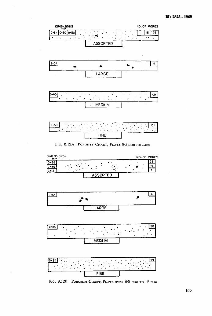
IS : 2925 - 1969
DIMEN-NIONS NO. OF PORES
-. . . .4: .:‘. * * . .:.:. . . . -.-
,,. .
I ASSORTED I
I
I I
LARGE I
. MEDIUM I
FIG. 8.12A POROSITY CHART, PLATE 6.5 mm OR LESS
DIMENSIONS.
0.6Yrn
NO. OF PORES
.:.* . . . . 35 . 0.66 . ‘.*. ‘*.‘.‘.. . ’ . l * ..*;.._ . l l . .
3.12 . *. l : ‘. ._ .
. *
I ASSORTED 1
L I
I LARGE I
I - . J
I MEDIUM I
FIG. 8.12B POROSITY CHART,PLATE OVER 6.5 mm TO 12 mm
105
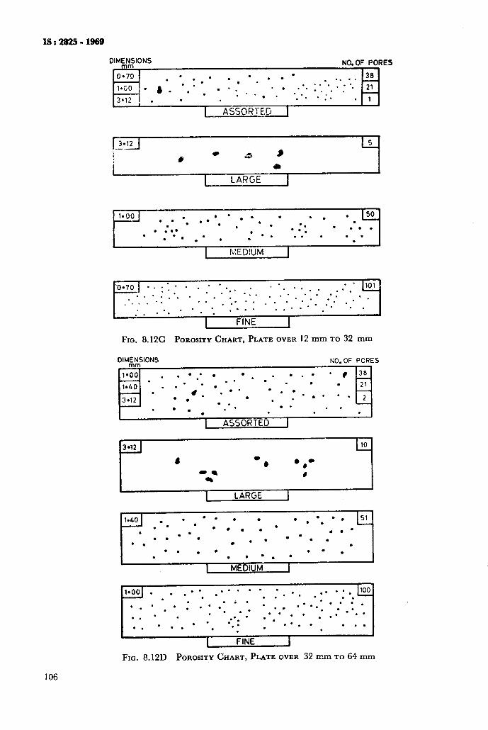
DIMENSIONS NO. OF PORES
0-70 . ’ . . l . l . l ’ . .* . . 38
l.(jO . ) . l . * . . .* - . . . *. 1.. ** * : *. 21 . .
3’12 . *.* . -.
. . . . .:. * 1
1 ASSORTED 1
r*coJ l . . . . . l . . . . . . 150 .
:.. l , l . 0.
. .
. . . . . l *.
. . l . ‘0 : . 0 l . . . . .
I fGED!UM I
..*... . . . . . . . -- . . . . . . . . . .
. . _... ..--* . ‘. . .
. . - *: . .
I FINE I
Fro. 8.12C POROSITY CHART, PLATE OVER 12 mm TO 32 mm
DhE.SIONS NO. OF PORES
44
i”y
l;)::-:i:l
~:
FIG. 8.12D POROSITY CHART, PLATE OVER 32 mm TO 64 mm
106
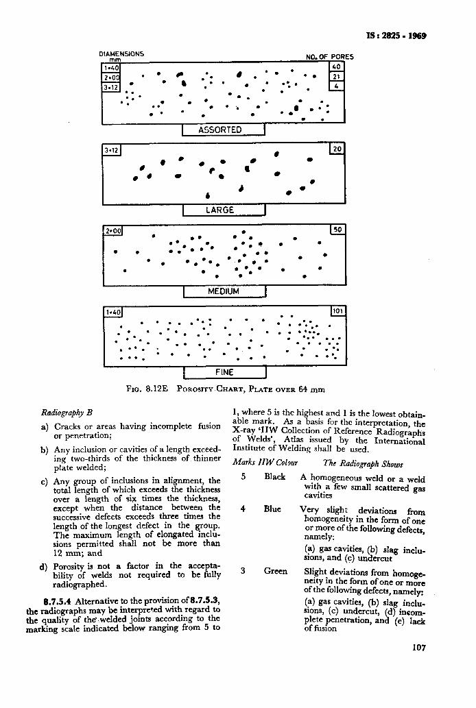
IS:2825-1969
DIAMENSIONS mm NO. OF PORES
1.40 40
2.00 l . -
3.12 . .
- 0. l . 0. l
. l . . l . . l l .
. . . l ‘. . 0’ l l . l .
a- . l : . .
1 ASSORTED 1
.
.
l
0’ l *
.
. 0. 0.. l
. . 0. l e. . l
.
.
.
.
.
.
l
l
L50
MEDIUM
~‘-;I~
I I
I FINE I
FIG. 8.12E POROSITY CHART, PLATE OVER 64 mm
Radiography B
a>
W
4
4
Cracks or areas having incomplete fusion or penetration;
Any inclusion or cavities of a length exceed- ing two-thirds of the thickness of. thinner plate welded;
Any group of inclusions in alignment, the total length of which exceeds the thickness over a length of six times the thickness, except when the distance between the successive defects exceeds three times the length of the longest defect in the group. The maximum length of elongated inclu- sions permitted shall not be more than 12 mm; and
Porosity is not a factor in the acce ta- bility of welds not required to be ully P radiographed.
8.7.5.4 Alternative to the provision of 8.7.5.3, the radiographs may be interpreted with regard to the quality of the.welded joints according to the marking scale indicated below ranging from 5 to
1, where 5 is the highest and 1 is the lowest obtain- able mark. As a basis for the interpretation, the :f-raW;fisW Collection of Reference Radiographs
‘, Atlas Issued by the International Institute of Welding shall be used.
Marks II W Colour The Radiograph Shows
5 Black A homogeneous weld or a weld with a few small scattered gas cavities
4 Blue Very slight deviations from homogeneity in the form of one or more of the following defects, namely: (a) gas cavities, (b) slag inclu- sions, and (c) undercut
3 Green Slight deviations from homoge- neity in the form of one or more of the following defects, namely: (a) gas cavities, (b) slag inclu- sions, (c) undercut, (d) incom- plete penetration, and (e) lack of fusion
107
lS:!28!25-1969
imrks IICV c010ur The Radiograph Shows
2 Brown Marked deviations from homo- geneity in the form of one or more of the following defects, namely:
(a) gas cavities, (b) slag in- clusions, (c) undercut,- (d) in- complete penetration, and (e) lack of fusion
1 Red Gross deviations from homo- gcneity in the form of one or more of the following defects, namely:
(a) gas cavities, (1~) slag inclusions, (c) undercut, (d) in- complete penetration, (c) lack of fusion, and (f) cracks
Welded joints in pressure, vessels which are required to be made in accordance with this code shall obtain a minimum of 4 marks in the radio- graphic examination.
Isolated films getting lower marks may, however, be accepted with the permission of the inspecting authority in each individual case.
8.7.6 Any repair to a weld carried out by the manufacturer shall be reported to the inspecting authority. If the repair is made as a consequence of a radiographic examination, the films of the original defects and after repiar of defects, shall be made available to the inspecting authority. If the defects form a continuous line, the extent of repair shall be agreed upon between the manu- facturer and the inspecting authority.
8.7.7 If a longitudinal seam fails to meet the . requirements of the code and it is desired to effect
a repair by removing the whole weldand rewelding .it, the original test plate shall becut and repaired to simulate condition of main seam weld. If it is not possible, a new production plate shall be provided.
8.7.8 If a circumferential seam fails to meet the requirements of the code and it is desired to effect a repair by removing the whole weld and rewelding it, the inspecting authority shall be en- titled to call for a new production plate, if required.
8.7.9 All repaired areas shall be subject to radio? graphic examination where radiography was originally required.
8.7 .lO Radiographic Examination
8.7.10.1 Zdentijcation of radiographs
a) Numerals shall be stamped on the vessel alongside the welded seams so that each radiograph may be identified with the portion of seam represented. The stamped impression shall be of a suitable radius; a stamp which produces a sharp-edged
108
b)
4
4
4
notch in the plate shall not be used. Where identification marks stamped on vessels are not deep enough to be radiographed, such markings may be radiographed with lead numerals or markers placed over them, with the previous consent of the inspecting authority.
Where radiographs are required of the entire length of a welded seam, sufficient overlap shall be provided to ensure that the radiographs cover the whole of the welded seam, and each radiograph shall exhibit a number near each end ( see Fig. 8.13 ).
Lead numerals shall be placed on the opposite side of the weld to the appropriate stamped numerals to provide ready identi- fication of the radiographs with the portion of welded seam represented ( see Fig. 8.13 ).
The width of the weld shall be indicated by suitable lead pointers placed on each side of, and clear of, the outside edges of the w\ ‘d. Alternatively, lead wires of small diameter, placed on each side of the weld and clear of, but not more than 3 mm from the outside edges of the weld, may be employed.
Lead characters shall be placed alongside the weld to provide the following informa- tion on the individual radiographs:
1)
2)
3)
The region of the welded seam covered bythe radiograph.
The location of the welded seam using a letter L for a longitudinal seam and C for a circumferential seam with the addition of a numeral ( 1, 2, 3, etc ) to indicate whether the seam was the first, second, or third, etc, of the type. Thus the second circumferential seam in a vessel would be marked 2C as shown in Fig. 8.14 ( see notes on Appendix L ).
Where the welded seam under exa- mination is contained in the jacket of a vessel, it is recommended that the letter J should be prefixed to the lead charac- ters denoting the location of the welded seam, for example, JL would represent the second longitudinal seam of the jacket.
For the particular vessel to which the radiographs apply, this identification could be provided by lead characters which indicate information, such as the works serial number, the order number or similar references. The result of the radiographic examination shall be detailed on a report form ( see Appendix L ) signed by the approved person responsible for the inspection. The report should be accompanied by a drawing or diagram showing the exact location of defects.
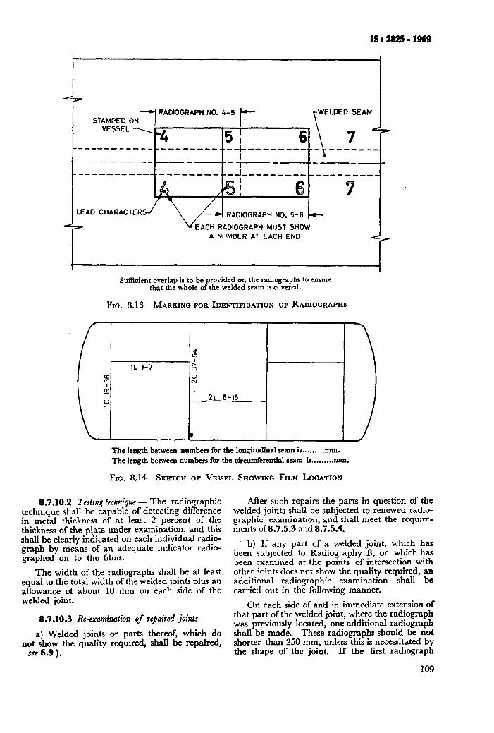
IS:282511969
STAMPED ON 1 RADIOGRAPH NO. 4-5 WELDED SEAM
VESSEL \
51 6 7&W \
--------_--____-__-_--.-- ---_---_.__ k
_______. -- - --- ‘--- ---------_--.-- -_---_.~-J___-,_,-,_,,,,,,,,,
I I 7 LEAD CHARACTERS RADIOGRAPH NO. 5-6 k
d-r EACH RADIOGRAPH MIJST SHOW A NUMBER AT EACH END d7
Sufficient overlap is to be provided on the radiographs to ensure that the whole of the welded seam is covered.
FIG. 8.13 MARKING FOR IDENTIFICATION OF RADIOGRAPHS
The length between numbers for the longitudinal seam is . . . . . . . . . mm.
The length between numbers for the circumferential seam is.........mm.
FIG. 8.14 SKETCH OF VESSEL SHOWING FILM LOCATION
8.7.10.2 Testing technique - The radiographic technique shall be capable of detecting difference in metal thickness of at least 2 percent of the thickness of the plate under examination, and this shall be clearly indicated on each individual radio- graph by means of an adequate indicator radio- graphed on to the films.
The width of the radiographs shall be at least equal to the total width of the welded joints plus an allowance of about 10 mm on each side of the welded joint.
8.7.10.3 Re-examination of repaired joints
a) Welded joints or parts thereof, which do not show the quality required, shall be repaired,
see 6.9 ).
After such repairs the parts in question of the welded joints shall be subjected to renewed radio- graphic examination, and shall meet the require- ments of 8.7.5.3 and 8.7.5.4.
b) If any part of a welded joint, which has been subjected to Radiography B, or which has been examined at the points of intersection with other joints does not show the quality required, an additional radiographic examination shall be carried out in the following manner.
On each side of and in immediate extension of that part of the welded joint, where the radiograph was previously located, one additional radiograp,h shall be made. These radiographs should be not shorter than 250 mm, unless this is necessitated by the shape of the joint. If the first radiograph
109

IS : 2825 - 1969
has been made at a point of intersection and ox a welded joint ending in this point, only one radio- graph is to be made in extension of the first one.
Should special conditions make it expedient, the inspecting authority has the right to modify the location of such additional radiographs.
c) Should the two additional radiographs made in accordance with (b) above meet the quali- ty requirements, the entire weld unit represented by the three radiographs is acceptable. The defective welding disclosed by the first of the three radiographs may be removed and the area repaired by welding or it may be allowed to remain there at the discretion of the inspecting authority.
d) Should any of the additional radiographs made in accordance with (b) above do not meet the qualitv requirements of 8.7.5.3 or 8.7.5.4, the entire unit of weld shall be rejected and the joint in questidn shall be radiographed throughout its entire length and shall be repaired where necessary, followed by a renewed examination of all repaired parts of the joint.
In addition to this, a further random radio- graphic examination shall be carried out on the other joints of the vessel in question, unless these joints have already been examined throughout their entire length. This additional examination shall comprise the same number of radiographs as prescribed for Radiography B. Should any of these additional radiographs fail to meet the requirements of 8.7.5.3 or 8.7.5.4, the joint in question shall be examined throughout its entire length and shall be repaired where necessary, followed by renewed examination, until the quality requirements have been met with.
Should the random radiographic examination of a vessel reveal. a larger number of systematic defects of such character that similar defects may be expected to occur to a greater or smaller extent in the welds as a whole, or in all welds of a certain category, the inspecting authority has the right to request an extension of the examination including a complete examination of all welds, or including all welds in the vessel within the category in question.
All parts of the welded joints, which do not meet the requirements stated under 8.7.5.3 or 8.7.5.4 shall be repaired and re-examined after repair.
e) No repairs shall be carried out after the radiographic examination without the prior con- sent of the inspecting authority.
f) Radiographic films Ball be preserved by the manufacturer for a period of at least five years after the acceptance of the films.
8.7.10.4 Protection of jwsonnel - All persons exposed to X or gamma rays and engaged in radiographic work shall be suitably shielded against direct and scattered radiations.
110
For detailed information, reference may be made to IS : 2598-1966*.
8.7.11 Other Non-destructive Testing MethA - When special conditions make it expedient, radio- graphy as specified in 8.7.1 and 8.7.2 may be re- placed by other non-destructive testing methods, for example, dye penetrant, magnetic or ultrasonic test- ing methods upon previous consent of the inspecting authority, and on the condition that such testing methods may be considered to render an equally safe evaluation of the quality of the welding work. Such non-destructive testing methods may also be employed to ascertain the quality of welds, where radiography cannot be easily employed as in the case of fillet and butt welds on branches and fittings.
See IS : 3664-1966?, IS : 4260-1967$, IS : 3658- 19665 and IS : 3703-196611.
9. MARKING AND RECORDS
9.0 All vessels built under this code shall conform to the provisions of this code in every detail and shall be distinctly stamped and certified.
9.1 Marking-Each pressure vessel shall have stamped upon its front plate in a conspicuous position the foliowing particulars:
Manufacturer’s name
Manufacturer’s serial No.
Year built
Max W.P . . . . . . . . . . . . . . . . . . . at Temp . . . . . . . . . . . . . . . . “C
IS : 2825 . . . . . . . . . . . . . . . . . .FRT/PR**/SRtt
Hydraulic pneumatic test pressure... . . . . . . . . . . . . . .
Date of test.. . . . . . . . . . .
Inspecting authority’s official stamp
9.1.1 The figures and letters of the stamping shall be at least 8 mm high when stamped directly on the vessel or 4 mm high when stamped on a permanently attached name-plate. The figures and letters shall be legible and stamped fully into the plate. Deep stamping shall be avoided when stamped directly on the vessel.
9.1.2 Stamping of vessels may be made directly on the vessel or may be stamped on a permanently attached name-plate so fixed as not to be covered by lagging or insulation. Permanently attached name-plates shall be used on all vessels of steel plate less than 7 mm thick.
*Safety code for industrial radiographic practice. tCode of practice for ultrasonic testing by pulse echo
method ( direct contact ).
in fZ%tic steel ccommcndcd practice for ultrasonic testing of welds
. QCode of practice for liquid pcnetrant flaw detection. IlCode of practice for magnetic flaw detection. FR, if fully radiographed ( Radiography A ).
*+PR , if spot or check radiographed ( Radiography 8. ) . ttSR, if stress-relicvcd.
9.1.3 The stamping area shall be painted and outlined in a contrasting colour. The stam ing or name-plate described in 9.1 and 9.13, P sha 1 be kept free of any covering.
9.1.4 Either of the following arrangements may be used in marking vessels having two or more independent pressure chambers designed for the same or different operating conditions. Each detachable chamber shall be marked so as to identify it positively with the combined unit:
a)
W
The marking may be grouped in one loca- tion .on the vessel, provided it is arranged so as to indicate clearly the data applicable to each chamber.
The complete required marking may be applied to each independent pressure chamber, provided additionai marking, such
IS : 2925 - 1969
as stock space, jacket, tube-nest or channel box is used to indicate clearly to which chamber the data apply.
9.1.4.1 Removable pressure parts shall be permanently marked in a manner to identify them with the vessel or chamber of which they form a part. This does not apply to manhole covers, handhole covers, etc.
9.2 Certificate of Manufacture and Test - A certificate of manufacture and test in form is given in Appendix M shall be filled out by the manufacturer and signed by the manufacturer or a responsible representative of the manufacturer and shall be complete with all the enclosure re- ferred to in form in Appendix M. The manu- facturer shall issue such a certificate for every vessel fabricated by him.
111

As in the Original Standard, this Page is Intentionally Left Blank
APPENDICES
APPENDIX A
APPENDIX B
APPENDIX C
APPENDIX D
APPENDIX E
APPENDIX F
APPENDIX G
APPENDIX H
APPENDIX J
APPENDIX K
APPENDIX L
APPENDIX M
APPENDIX N
.
ALLOWABLE STRESS VALUES FOR FERROUS AND NON-FERROUS MATERIAL . . .
ELEVATED TEMPERATURE VALVES FOR CARBON AND Low ALLOY STEELS WITH UNCERTIPIED HIGH TEMPERATURE PROPERTIES
STRESSES FROM LOCAL LOADS ON, AND THERMAL GRADIENTS IN, VESSELS
TENTATIVE RECOMMENDED PRACTIOE FOR VESSELS REQUIRED TO AT Low TEMPER.~T~REs
TENTATIVE RECOMMENDED PRACTICE TO AVOID FATI~VE CRACRINQ
. . .
PRESSURE . . .
OPERATE . . .
. . .
ALTERNATE MET~I~D IOR DETERMINING SHELL THICKNESSES OF CYLINDRICAL AND SPIIERI~AL VESSELS UNDER EXTERNAL PRESSURE BY USE OF CHARTS . . .
TYPICAL DESIGN OF WELDED CONNECTIONS . . .
PRG’ FOXMA FOR TIIE RFXORD OF WELDING PR~CEDVRE QUALIFICATION/ WELDER PERFORMANCE QUALIFXCATI~N TEST . . .
WELDING OF CLAV STEEL AND APPLICATION OF CORROSION-RESISTANT LININGS .,.
METSIOD OF PREPARING ETCHED SPECIMEN . . .
PRO FORMA FOR REPORT OF RADIOGRAPHIO EXAMINATION . . .
PRO FORMA FOR MAKER’S CERTIFICATE OF MANUFACTURE AND PRODUCTION TEST . . .
INSPECTION, REPAIR AND ALLOWABLE WORKING PRESSURE FOR VESSELS IN SERVICE’ . . .
115
124
126
175
178
180
195
224
226
231
232
233
235
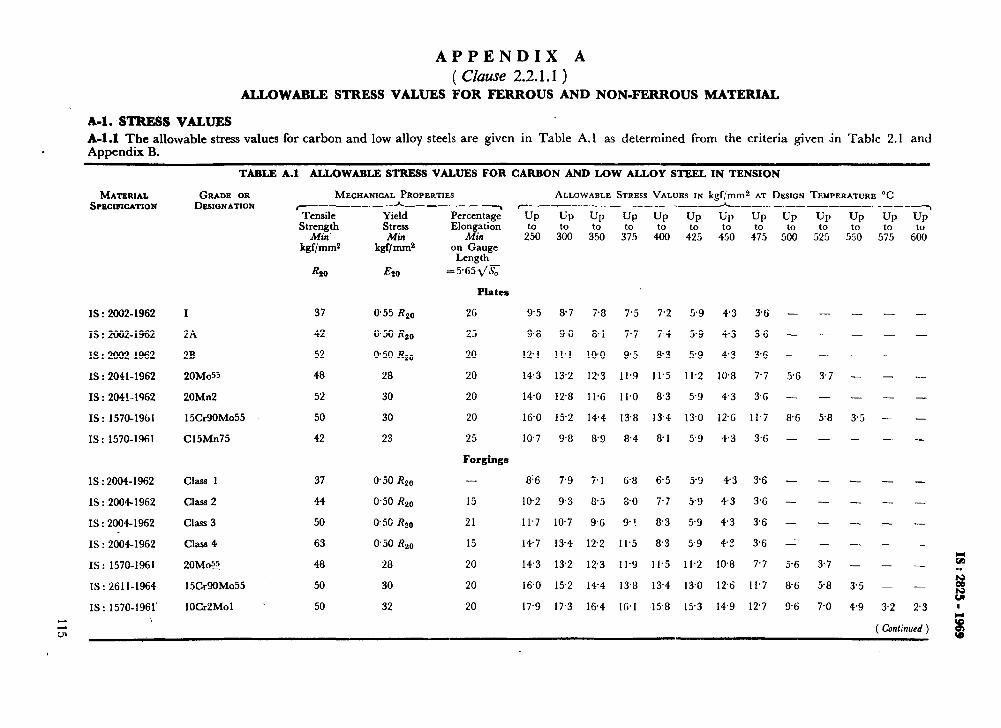
APPENDIX A ( CZause 2.2.1.1 )
ALLOWABLE STRESS VALUES FOR FERROUS AND NON-FERROUS MATERIAL
A-l. STRESS VALUES A-l.1 The allowable stress values for carbon and low alloy steels are given in Table A.1 as determined from the criteria given in Table 2.1 and Appendix B.
TABLE A.1 ALLOWABLE STRESS VALUES FOR CARBON AND LOW ALLOY STEEL IN TENSION
GRADE OR MECHANICAL PROPERTIES ALLOWABLE STRESS VALUES IN kgf/mm2 AT DW~N TEMPERATURE “C DESIGNATION F_--_--- __-_--_-_ -------___--____--_-___h___._ _.____~__. _--_-~
Tensile Strength
Min. kgf/mms
Yield Stress Min
kgf/ mm2
E20
Percentage’ Elongation
Min on Gauge Length
=5*652/K
UP UP UP UP UP UP up up
2f50 3’o”o 3% 3% 4% 4% 4?0 4f75
UP
51po
UP
5T5
UP to
5.50
UP
std;
&o
MATERIAL SPECWICATION
37 0.55 RzO
42 0.50 Rzo
52 0.50 Rzo
48 28
52 30
50 30
42 23
Class 1 37
Class 2 44
Class 3 50
Class 4 63
20M@ 48
15Cr9OMo55 50
lOCr2Mol 50
0.50 RzO
0.50 R20
@5U Rzo
@50 Rzo
28
30
32
-.
-
-
-
-
-
-
-
-
-
-
t: - . .
- ii s
2.3 ’
Plates
26
25
20
20
20
20
25
Forgings
9.5 8.7 7.8 7.5 7.2 5.9 43 3% -
9.8 90 8.1 7.7 7.4 5.9 4.3 3.6 -
12.1 11.1 l@O 95 8.3 5.9 43 3.6 -
143 132 123 11.9 11.5 11.2 10.8 7.7 5.6
140 128 11.6 11.0 8.3 5.9 43 3.6 -
16.0 15.2 1+4 13.8 134 13.0 12.6 11.7 8.6
10.7 9.8 8.9 8.4 8.1 5.9 4.3 3.6 -
IS : 2002-1962 I
IS : 2002-1962 2A
IS : 2002-1962 2B
IS : 2041-1962 20MdL
IS : 204!-1962 20Mn2
IS : 1570-1961 15Cr9OMo55
IS : 1570-1961 C15Mn75
-
-
-
3.7
-
5.8
-
-
-
-
-
3.5
-
-
IS : 2004-1962
IS : 2004-1962
IS : 2004-1962
8’6 7.9 7.1 6.8 65 5.9 4.3 3.6
102 9.3 &5 8.0 7.7 5.9 43 3%
11.7 107 9.6 9! 8.3 5.9 4.3 3.6
147 134 12.2 11.5 8.3 5.9 4? 36
14.3 132 12.3 11.9 11.5 11.2 10.8 7.7
16.0 15.2 144 13.8 134 13.0 12.6 11.7
17.9 17.3 16.4 16.1 15.8 15.3 14.9 12.7
- -
-
-
15
21
15
20
20
20
- -
IS : 2004-1962
IS : 1570-1961
IS : 261 l-1964
IS : 1570-1961
z
- -
5.6 3.7
86 58
9.6 7.0 3.2
( Confinuad ) i
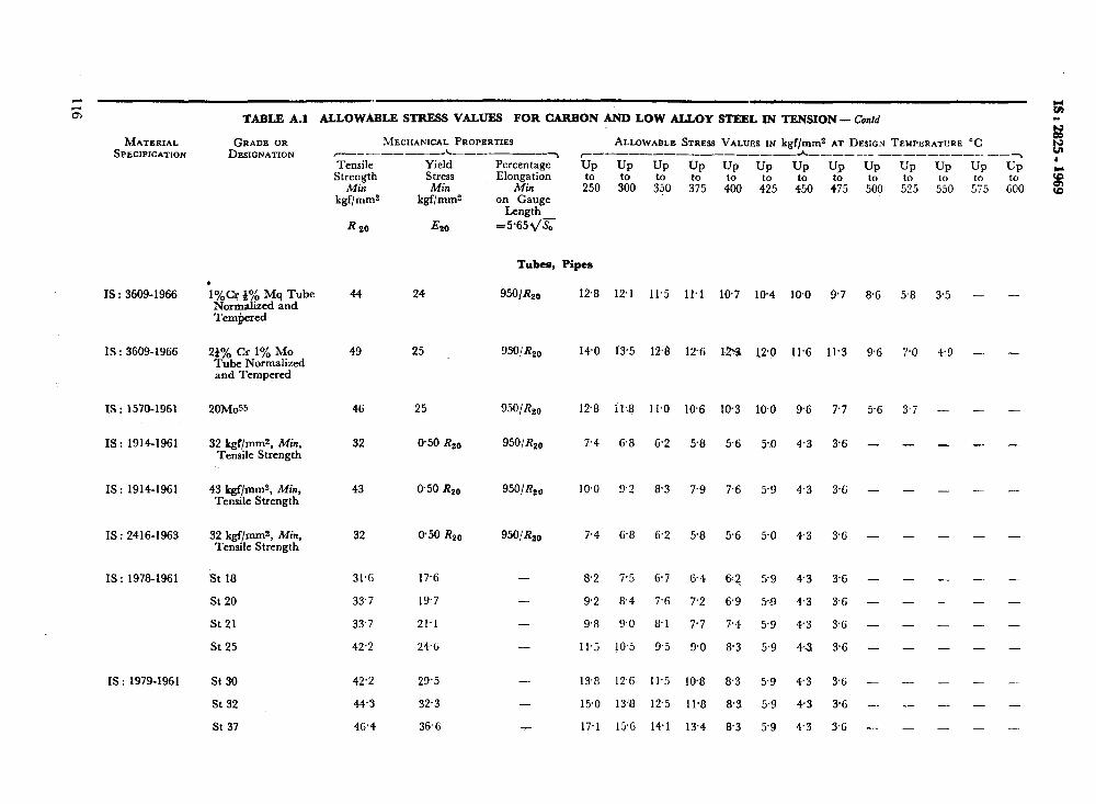
MATERIAL SPECIFICATION
IS : 3609-1966
IS : 3609-1966
xs : 1570-1961
IS : 1914-1961
IS : 1914-1961
IS : 2416-1963
IS : 1978-1961
IS : 1979-1961
TABLE A.1 ALLOWABLE STRESS VALUES FOR CARBON AND LOW ALLOY STEEL IN TENSION- Contd
GRADE OR MECHANICAL PROPERTIES DESIGNATION ~__________c___
ALLOWABLE STRESS VALUES IN kgf/mms AT DESIGN TEMPERATURE “C 7 c-------- ~_______h____-__ .-------__ --7
Tensile Strength
Mitl kgf/mms
R 20
44
Yield Stress Min
kgf/mms
~520
24
Percentage Up Up Up Up Up Up Up Up Up Elongation
Min 20 4;5 4;o :;5 L%l on Gauge
Length =5*65dg
UP UP to 535 L 5%
UP UP to 575 EZO
Tubes, Pipes
. le/&r J”/:, Mq Tube Nor aliaed and Tern red %
950/&o 12.8 12.1 11.5 11.1 197 164 190 97 86 5.8 3.5 - -
- -
- -
- -
- -
- -
- -
- -
- -
- -
- -.
- _
- -
24% Cr 1% MO Tube Normalized and Tempered
2OMoSS
32 kgF/mms, Min, Tensile Strength
43 kgf/mms, Min, Tensile Strength
32 kgf/mms, Mitt, Tensile Strength
St 18 31.6 17.6
St 20 33.7 19.7
St 21 33.7 21.1
St 25 42.2 246
St 30
St 32
St 37
49 25
46 25
32 @SO Rzo
43 950 Rzo
32 0.50 R20
42.2 29’5
44.3 32.3
46.4 36.6
9WK20 140 13.5 128 12-G 12% 12.0 Il.6 11.3 9.G
950/&o 128 il.9 11.0 10.6 103 l@O 9.6 7.7 5.6
95OlR2o 7.4 6.8 6.2 58 5.6 5.0 4.3 3.6 -
95O/R,o IO.0 9.2 8.3 7.9 7.6 5.9 4.3 3.G -
950,‘R20 7.4 6.8 6.2 58 5.6 5.0 43 3.G -
-
-
-
-
-
-
82 7.5 6.7 64 tXJ 5-9 4-3 3% -
92 8.4 7.6 7.2 6.9 5-3 4.3 3.6 -
9.8 9.0 8.1 7.7 7.4 5.9 4.3 3.G -
Il.5 10.5 9.5 9.0 8.3 5.9 43 3.6 -
13.8 12.6 11.5 10.8 83 5.9 4.3 3.c -
15.0 136 12.5 11.8 8.3 59 43 3G -_
17.1 15% 141 134 8.3 5.9 43 3.G -
7.0 4.3
3.7 -
- -
- -
- -
- -
- -
- -
- -
- -
*- -
- -
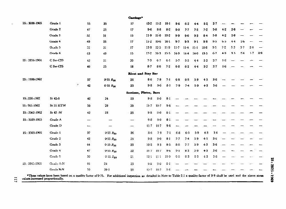
IS : 3038-1965 Grade 1
Grade 2
Grade 3
Grade 4
Grade 5
Grade 6
IS : 2856-1964 C SW-G20
C SW-cm
IS: 199or1962
1Sx 226-1962
IS : 961-1962
IS : 2062-1962
IS : 3039-1965
IS : 3503-1966
IS : 3945-1966
St 42-S
St 55 HTW
St 42 -W
Grade A
Grade D
Grade 1
Grade 2
Gtidc 3
Grade 4
Grade 5
Grade A-N
Grade B-N
55
47
52
49
52
63
42
49
37
r 42
42 24
50 29
42 23
37 0.55 Rl,,
42 0.55 Rzo
44 0.55 Rzo
47 0.55 R,,,
50 055 R,,,
44
50
24
28.5
35
25
31
28
31
43
21
25
O-55 RL,,
@55 Rl,,
-
-
-+
17 12.2 11.2
17 9.6 8.8
15 Il.9 ll.0
17 11.2 10.6
17 13.0 12.5
15 17.2 16.3
20 7.3 6.7
18 8.7 8.0
Rivet 8bd stay Bar
26 8.6 7.9
23 9.8 90
Sections, Plates, Bars
23 9.8 9.0
20 11.7 10.7
23 98 9.0
- 9.8 9.0
- 11.7 10 7
26 86 79
25 98 9.0
23 IO-2 9 3
22 11.7 10.7
21 12’1 11.1
23 9.8 9.0
20 11.7 10.7
10.1 9.6 6.2 4.4 3.2, 2.7 - -
8.2 8.0 7.7 7.5 3.1 5.8 4.2 2.8
10.2 9.9 9.6 9.3 8.4 5.8 4.2 2.8
10.1 9.7 9.3 9.1 8.8 8.5 6.5 4.4
11.9 11.7 11.4 11.1 10.8 9.5 7.2 5.3
15.5 14.9 14.4 14.0 13.5 6.7 4.9 3 5
6.1 5.7 5.5 4.4 3-2 2.7 1.6 -
7.2 6.8 6.2 4-4 3.2 2.7 l-6 -
7.1 6.8 6.5 5.9 4.3 3.6 - -
8.1 7.9 7.4 5.9 4.3 3.6 - -
8.1 - _ - _ _ _ _
9.6 _ _ _ _ _ _ _
8.1 _ - _ _ - - -
8.1 _ _ _ _ - _ -
9.6 _ _ _ _ - _ -
7.1 6.8 6.5 5.9 4.3 3.6 - -
8.1 7.7 7.4 5 9 4.3 3,6 - -
8.5 8.0 7.7 5.9 4.3 3.6 - -
9.6 9.1 8.3 5.9 4.3 3.6 - -
10 0 9.5 8.3 5.9 4 3 3.6 - -
8.1 _ - - - _ - _
9.6 _ _ - _ - _ _ - - -
- - -
- - -
- - -
2.6 - -
3.7 2.4 -
2,6 1.7 0.9
- - -
- - -
- - -
- - -
- - -
- - -
- - -
- - -
- - -
fi: . .
!i ul I
z *l&w valua have bee-n based on a quality factor of 0.75.
valua+sascd proportionally. For additional inspection as detailed in Note to Table 2.1 a quality factor of @9 shall be used and the above stress
q f
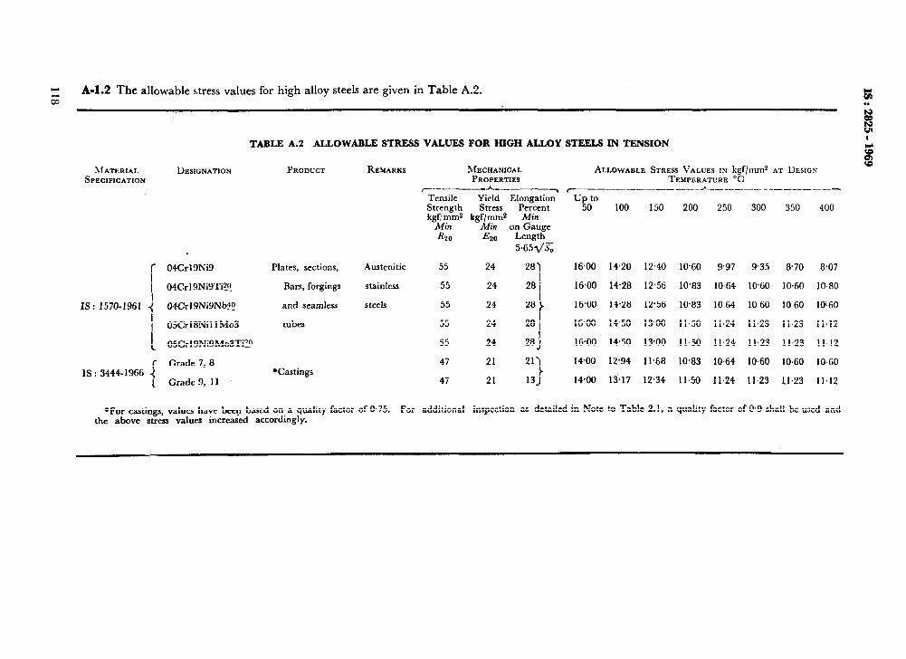
c
z A-l.2 The allowable stress values for high alloy steels are given in Table A.2. ;: . .
% c?
TABLE A.2 ALLOWABLE STRESS VALUES FOR HIGH ALLOY STEELS IN TENSION I w
: 04Cr’gNig 1 04Crl9Ni9Tig
IS: 1570-1961 4 04Crl9Ni9Nb$
1 05Crl8Nil lMo3
I 05Crl9Ni9Mo3Ti?!!
r Grade 7, 8 IS: 3444-1966 (
( Grade 9, 11
PRODUCT
Plates, sections,
Bars, forgings
and seamless
tubes
*Castings
REMARKS MECHANICAL PROPERTIES
~-_--_*_---___~ Tensile Yield Elongation Strength Stress Percent kgf:rnms kgf/mms Min
Min Min on Gauge Rzo E20 Length
5,651/s
Austenitic 55 24 281
stainless 55 24 281
steels 55 24
’
55 24 28 I 28 I
55 24 28)
47 21 211
ALLOWABLE STRESS VALUES IN kgf/tnmz AT DESIGN TEMPIZRATURE “C
c-.------_-_ -__. ~._---_-___------~ up to
50 100 150 200 250 300 350 400
16.00 14.20 12.40 1060 9.97 935 870 8.07
1680 1428 12.56 10.83 10.64 10.60 10.60 10.80
16.00 14.28 12.56 1@83 1064 10 60 10 60 1060
16+8 1450 13.00 11.50 11.24 11.23 11.23 11.12
16.00 1450 13.00 11.50 11.24 11.23 11.23 11.!2
1400 12.94 11.88 10.83 10.64 10.60 10.60 10.60
47 21 131 1480 13.17 12.34 11.50 11.24 11.23 Il.23 11.12
*For castings, values have been based on a quality factor of 0.75. For additional inspection as detailed in Note to Table 2.1, a quality factor of 0.9 shall be used and the above stress values increased accordingly.
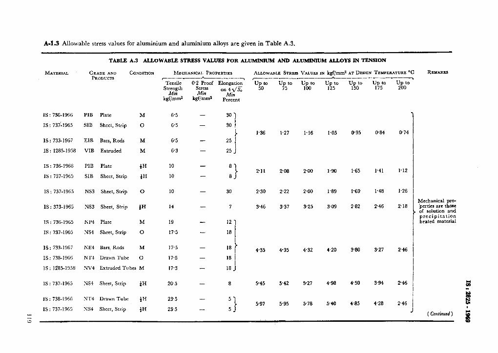
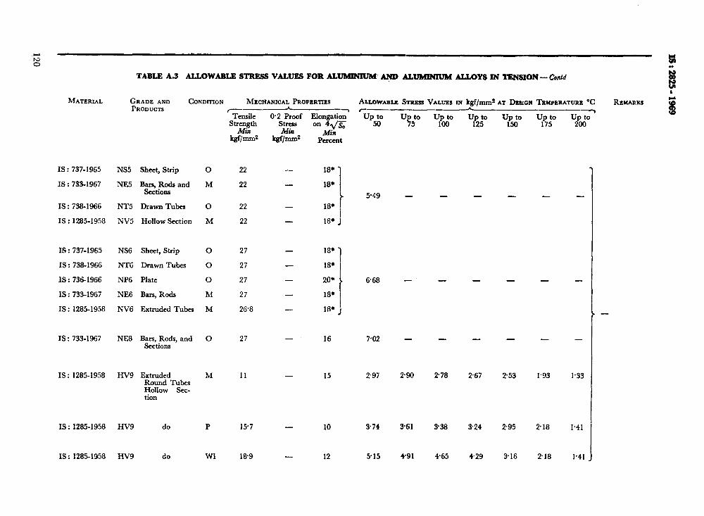
TABLE A.3 ALLOWABLE STRESS VALUE8 FOR AL- AI!ID AL- ALLOYS IN TENSION- Contd
MATERIAL GRADE AND CONDITION MECHANICAL PROPERTIES PRODUCTS
IS : 737-1965 NS5 Sheet, Strip 0
IS : 733-1967 NE5 Ban, Rods and M SectiOUS
IS : 738-1966 NT5 Drawn Tubes 0
IS : 1285-1958 NV5 Hollow Section M
IS : 737-1965 NS6 Sheet, Strip 0 27
IS : 738-1966 NTG DrawnTubes 0 27
IS : 736-1966 NP6 Plate 0 27
IS : 733-1967 NE6 Bars, Rods M 27
IS : 1285-1958 NV6 Extruded Tubes M 26.8
IS : 733-1967 NE8 Bars, Rods, and 0 Sections
IS : 1285-1958 HV9 Extruded M Round Tubes Hollow Sec- tion
IS : 1285-1958 HV9 do P
IS: 1285-1958 HV9 do Wl
_---___A__,
Tensile SbIIgth
Mi?J w-2
0.2 ?roof Elongation. StrerS Min
on 41/S;;
W/-2 Min
Pcrcent
22
22
22
22
27
11
15.7
l&9
- 18.
- 18+
- 18*
- 18,
- 18* f
- 18*
- 208
18* I -
- 18* J
- 16 7.02 - - - -
- 15
- 10
- 12
AJJLOWABUZ STRESS VALL’ES IN kgf/mm2 AT DESIQN TEMPERATURE “C fl- -_I --
up to 50
5.49 -
6.68 -
-
2.97 290 278 267 253 1.93
374 3.61 338 324 295 2.18
515 4.91 4.65 429 3.16 218
- -
- -
7%
-
-
U2P$ -
-
-
-
1.33
I.41
1.41
-
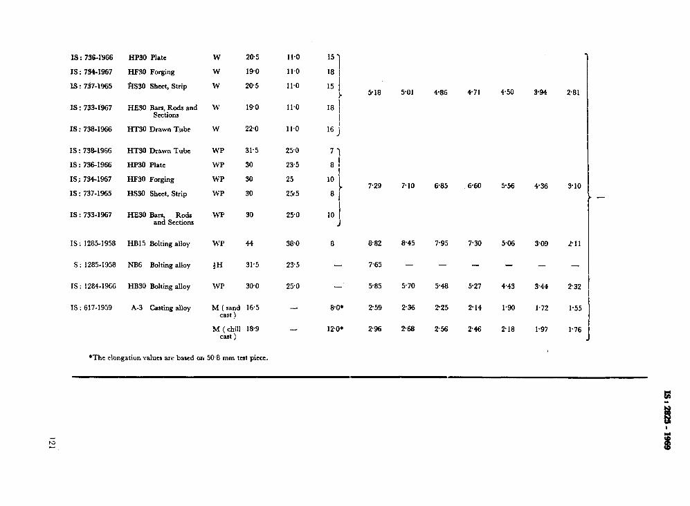
IS : 736-IYG6
IS : 734-1967
IS : 737-1965
IS : 733-1967
IS : 738-1966
IS : 738-1966
IS : 736-1966
IS : 7341967
IS : 737-1965
IS : 733-1967
IS: 1285-1958
S : 1285-1958
IS : 1284-1966
IS : 617-1959
HP30 Plate
HF30 Forging
$IS30 Sheet, Strip
HESO Bars, Rods and sections
HT30 Drawn Tube
HT30 Drawn Tube
HP30 Plate
HF30 Forging
HS30 Sheet, Strip
HE38 Bars, Rods and Sections
HB15 Bolting alloy
NB6 Bolting alloy
HB30 Bolting alloy
A-3 Casting alloy
W
W
W
w
W
WP
WP
WP
WP
WP
WP
tH
WP
20.5 11.0
190 11.0
20.5 11.0
190
220
31.5
30
30
30
30
44
31.5
30.0
11.0
11.0
250
23.5
25
25r5
25.0
38.0 8 8.82 8.45 7.95 7.30 506 309 211
23.5
25.0
- M (sand 16.5 cast !
M (chill l&9 cast )
*The elongation values are based on 508 rnxn tat piece.
15’) I
‘8 I
15 I
r I8 I
I I6 J
71 81
! 10
8 i
i IO i
J
-
-
8.0.
12’0*
518 5-01 4-86 4-71 4.50 394 281
729 7.10 6-85 6.60 5.56 436 310
7.65 - - - - -
585 570 5.48 5-27 443 344 ?32
259
296
236 2.25
2.68 2.56
2-14
2-46
1.90 1.72 1.55
2.18 1.97
1
1.76
N
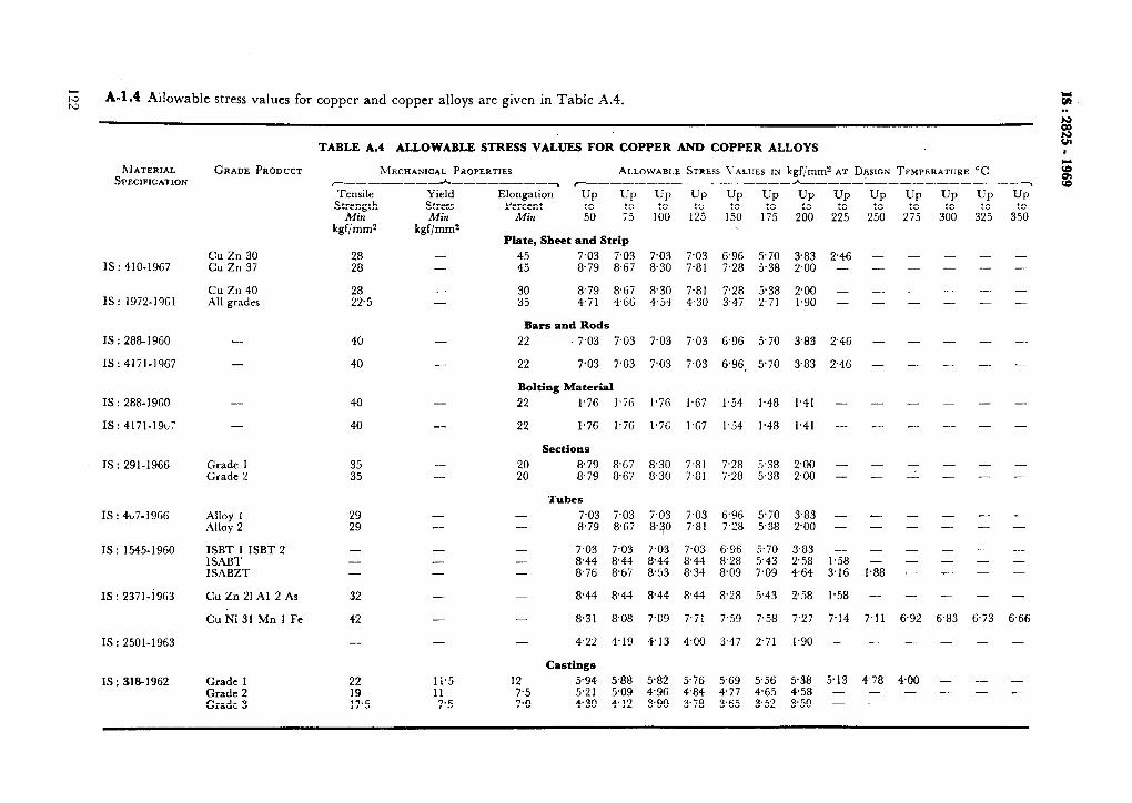
:;: A-1.4 Ailowable stress values for copper and copper alloys are given in Table A.4. t: . .
E
TABLE A.4 ALLOWABLE STRESS VALUES FOR COPPER AND COPPER ALLOYS
MECHANICAL PROPERTIES ALLOWABLE STRESS \'ALUES IN kgf,‘mm? AT DESIGN TEMPERATURE “C ,__________h_________ ~__-_______--_______h------_--_--.----_
’ Tensile Yield Strength stress
Afin Min kgf/mms kgf/mms
. r
Elongation Up Up rercent
Lz to
Min 75
Plate, Sheet and Strip
UP
lb”0
UP
2%
UP
2:
up
2505
UP
3;
28 - 4:
7.03 7.03 7.03 7.03 6.96 5.70 383 246 - 28 - 879 8.67 8.30 7.81 7.28 5.38 2.00 - -
- -
Cu Zn 40 28 All grades 22.5
40
40
- -
-
-
30 879 8.67 35 4.71 4,GG
Bars and Rods
22 7.03 7.03
22 7.03 7.03
8.30 7.81 7.28 5.38 2.00 - - 4.54 4.30 3.47 2.71 1.90 - -
- -
- -
7.03 7.03 G.96 5.70 3.83
7.03 7.03 6.96. 5.70 383
2.46 - - -
2.4G - - -
UP
3%
- -
- -
-
-
I
5; -7 s UP
St500
- -
- -
~IAT&IAL SPECIFICATION
GRADE PRODUCT
Bolting Material
1.76 l.iG 1.7G 1.67 1.54 1.48 1.41 - -
1.76 1.7G 1.7G l.G7 1.54 1.48 1.41 - -
Sections
8.79 8.79
8.67 8.30 7.81 7.28 5.38 2.00 - - 8.67 8.30 7.81 7.28 5.38 2.00 - -
Tubes
7.03 8.79
- -
- - 7.03 - - 8.44 - - 8.76
8.44
8.31
- - 4.22
7.03 7.03 7.03 6.96 5.70 3.83 - 8.67 8.30 7.81 7.28 5.38 2.00 -
7.03 7.03 7.03 6.96 5.70 3.83 8.44 8.44 8.44 8.28 5.43 2.58 1% 8.67 853 8.34 8.09 7.09 4.64 3.16
8.44 8.44 8.44 8.28 5.43 2.58 1.58
8.08 7.89 7.71 7.59 7.58 7.27 7.14
4.19 4.13 4.00 3.47 2.71 1.90 -
-
l-88
-
7.11
-
Castings
5.94 5.2 1 4.30
5.88 582 5.76 5.69 5.56 5.38 5.13 4- 78 5.09 496 4.84 4.77 4.65 458 - - 4.12 3.90 3.78 3.65 3.52 3.50 - -
-
--
- -
- -
- - -
-
6.83
-
- - -
Cu Zn 30 Cu Zn 37 IS : 410-1967
IS: 1972-19Gl
IS : 288- 19GO
IS: 4171-1967
IS : 288-19GO
IS: 4171-19L7
IS: 291-1966
IS : 4u7-196G
IS: 1545-1960
IS : 2371-1963
IS : 2501-1963
IS : 318-1962
-
-
- -
- -
- - -
-
6.92
-
400 - -
- 22
-_ 22
40
40 -
Grade 35 - Grade 35 - 5: -
- -
- - -
-
6.73
Alloy I Alloy 2
- - - -
ISBT 1 ISBT 2 ISABT IS?\BZT
- - -
32
42
CuZn2lAl2As
Cu Ni 31 Mn 1 Fe
-
Grade 1 Grade 2 Grade 3
22
z.5
li.5 12 11 7.5 ;:;
- - -
IS : 2825 - 1969
A-2. LIST OF INDIAN STANDARDS ON MATERIALS SPECIFIED IN TABLES A.1 TO A.4
Sl No. of the .NO. Standard
1) IS : 288-1960
2) IS : 291-1961
3) IS : 318-1962
4) IS : 320-1962
5) IS : 407-1966
6) IS : 410-1959
‘1 IS : 617-1959
8) IS : 733-1967
9) IS : 734-1967
10) IS : 736- 1965
11) IS : 737-1965
12) IS : 738-1966
13) 14)
IS : 961-1962 IS : 1284-1966
15) IS : 1285-1968
16) IS : 1385-1959
1’) 1s : 1545-1960
18) IS : 1570-1961
18) IS : 1914-1961
20) IS : 1972-1961
21) IS : 1978-1961
22) IS : 1979-1961
23) IS : 1990-1961
24) .IS : 2002-1962
25) IS : 2004-1962
26) IS : 2040-1962
2’) IS : 2041-1962
28) IS : 2062-1969
29) IS : 2371-1963
30) 31) 32)
IS : 2416-1963 IS : 2501-1963 IS : 2611-1964
33)
34)
35) 36) 3’)
38)
39) 40)
IS : 2856-1964
IS : 3038-1965
IS : 3039-1965 IS : 3444-1966 IS :3503-1966
IS : 3609-1966
IS : 3945- 1966 IS : 4171-1967
‘l%le
Specification f;zr copper rods for boiler stay bolts and rivets ( revised) Specification for~naval brass rods and sections ( suitable for machining and forging ) ( reuis~d )
Specification for leaded tin bronze ingots and castings ( revised ) Specification for high tensile brass rods and sections ( revised ) Specification for brass tubes for general purposes ( second revision ) Specification for rolled ,brass steel plate, sheet, strip and foil ( revised ) Specification for aluminium and aluminium alloy ingots and castings for gener- al engineering purposes ( revised )
Specification for wrought aluminium and aluminium alloys, bars, rods and sections ( for general engineering purposes ) (jirst revision )
Specification for wrought aluminium and aluminium alloys, forgings ( for general engineering purposes ) ( jrst rezhiorz )
Specification for wrought aluminium and aluminium alloys, plate ( for general engineering purposes ) ( rev&d )
Specification for wrouehr aluminium and aluminium alloys, sheet and strip ( for general engineermg purposes ) ( revised )
Specification for wrought aluminium and aluminium alloys, drawn tube ( for general engineering purposes ) ( revised )
Specification for structural steel ( high tensile ) ( revised) Specitication for wrought aluminium alloys, bolt and screw stock for general engineering purposes ( revised )
Specification for wrought aluminium and aluminium alloys, extruded round tube and hollow sections ( for general engineering purpose; ) ( revised )
Specification for phosphor bronze rods and bars, sheet and strip, and wire Specification for solid drawn copper alloy tubes Schedules for wrought steels for general engineering purposes Specification for carbon steel boiler tubes and superheater tubes Specification for copper plate, sheet and strip for industrial purposes Specification for line pipe Specification for high test line pipe Specification for steel rivet and stay bars for boilers Specification for steel plates for boilers Specification for carbon steel forgings for general engineering purposes Specification for steel bars for stays Specification for steel plates for pressure vessels Specification for structural steel ( fusion welding quality ) (Jirst revision ) Specification for solid drawn copper alloy tubes for condensers, evaporators,
heaters and coolers using saline and hard water Specification for boiler and superheater tubes for marine and naval purposes Specification for copper tubes for general engineering purposes Specification for carbon chromium molybdenum steel forgings for high tem-
perature service Specification for carbon steel castings suitable for high temperature service
( fusion welding quality ) Specification for alloy steel castings for pressure containing parts suitable for
high temperature Specification for structural steel ( shipbuilding quality ) Specification for corrosion resistant steel castings Specification for steel machinery structures
for marine boilers, pressure vessels and welded
Specification for chrome molybdenum steel, seamless, boiler and superheater tubes
Specification for steel for naval purposes Specification for copper rods for general engineering purposes
123
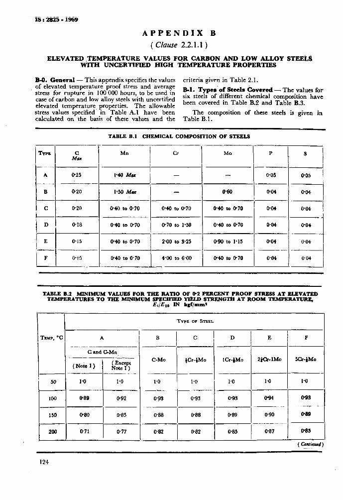
xs:2s25-1969
APPENDIX B
( Clause 2.2.1.1 )
ELEVATED ,TEMPERATURE VALUES FOR CARRON AND LOW ALLOY STEELS WITH UNCERTIFIED HIGH TEMPERATURE PROPERTIES
R-0. General - This appendix specifies the values criteria given in Table 2.1. of elevated temperature proof stress and average stress for rupture in 100 000 hours, to be used in R-1. Types‘of Steels hovered - The values for
case of carbon and low alloy steels with uncertified six steels of different chemical composition have
elevated temperature properties. The allowable been covered in Table B.2 and Table B.3.
stress values specified in Table A.1 have been calculated on the basis of these values and the
The composition of these steels is given in Table B.l.
TABLE B.l CHEMICAL COMPOSITION OF STEELS
_-
MI! / cr
_ ._
_-
- _
-_
--
I
MO I p I s I TYPS A&
A 0.25 -.---
B 0.20
C 0.20
D 0.18
E 0.15
---~ - O-05 005
0’60 0.04 @04 1.50 Mu I -
I I I- I
0.40 to 0.70 0.04 0.04
0.40 to -0.70 0.04 0.04
1 ado to 0.70 0.70 to 1.50
0.40 to 0.70 290 to 3.25
4*00 to 6ao
0.90 to 1.15 0.04 0.04 ~_.__ _
0.40 to 0.70 0.04 0.04 ! I F o-t5
TABLE B.2 MINIMUM VALUES FOR THE RATIO OF 02 PERCENT PROOF STRESS AT ELEVATED TEMPERATURES TO THE MINIMUM SPECIFIED YlELD STRENG~ AT ROOM TEMPERATURE,
Et/Es0 IN kgf/mm2
i- TYPE OF STEEL
I -
A
-
--
-.-
_-
-
B I
C D I E TEMP, W
I-- C and C-Mn
.-- --
( Note 1) kZy _-- _
1 Cr-fMo 2tcr- 1Mo
-.p--
1.0 1.0
C-MO gr-fM0
-I .-_-_-
1.0 1.0 .~--
og 0.93
50 1.0
I
0.93 I cP94 o-93 I 0.89 I o-92 100
150
,-
200
- --
W88 1
0.88 O-89 I o-90 o-89 I 0.80 0.85
‘0.71 0.77 I
0.82 I
0.82 0.85 I
0.87 Q85 I
124
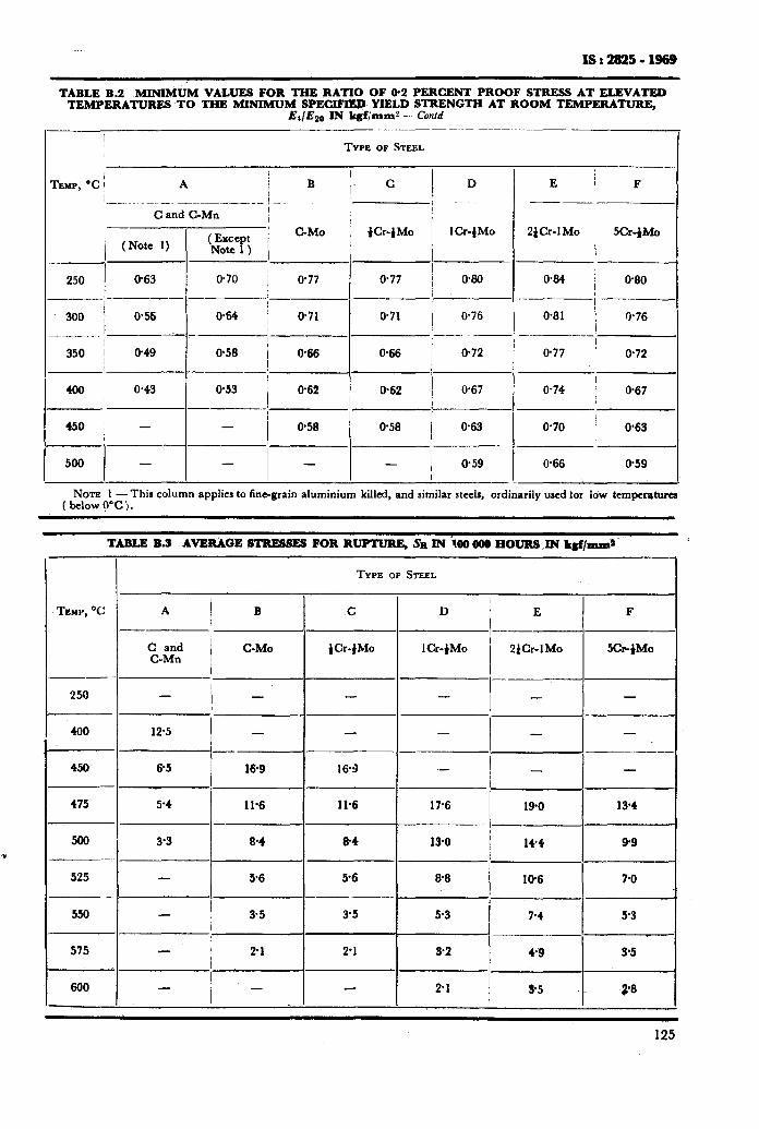
xs:2825-1969
TABLE B.2 MINIM& VALUES FOR THE RATIO OF 02 PEIUXNT PROOF STBESS AT ELEVATED TEMPERATURES TO THE MINIMUM SPECIFIEl? YIELD STRENGTH AT ROOM TEMPBBATUBB,
Et/E20 IN kgfjmml - Confd _________ ._ .~___._____
I
TYPE OF STEEL
TEMP, ‘C / I I
A B ,I C I
D I
C and C-Mn I I I
(Except / C-MO p-fM0 1 Cr-1 MO (Note 1) Note 1 ) i I
/ 250 963 0.70 / O-77
-..-_ --~-
300 0.71
--- j_- -- / 350 ! 0.49 @58 / 066
I -’ I / 400 0.43 0.53
I 662
-----__I
450 - - @58 -___
677 @&l
671 il.76
I__. -
066 672
0.62 0.67
-
0.58 663
- 0.59
-
I
E
__~~__F___
ZfCr-1Mo I SCr-fMo
I 0% I 680
I ----- 0.81 0.76 -.___-_
0.77 !
I 0.72
0.74 I 667
0.70 I 0.63
0.66 1 0.59
NOTE 1 -This column applies to fine-grain aluminium killed, and similar steels, ordinarily used for low temperatures (bclow?T.j.
TABLE B.3 AVERAGE STRESSES FOR RUPTUBE, sn IN ioo ooo HOURS ,M k&llm~
TYPE OF STEEL
TENP, ‘C A c D ’ E F ! i---
C and C-Mn / C-MO fCr-jMo lCr-)Mo 2&r-1Mo SCr- fM0
I ---
259 - / - - - -
400 12.5 - - - - -
I--- -- -__
450 65 169 163 .- 1 - -
475 54 11.6 11.6 17.6 190 184
----.__._-
500 3’3 8-4 8.4 13-O 144 99 - --
525 56 56 @8 IQ6 7.6 - --- - ._.
550 - 35 35 53 7.4 53 I --___
575 , 21 21 32 49 3-5 I
660 / __ - 21 95 2.8
125
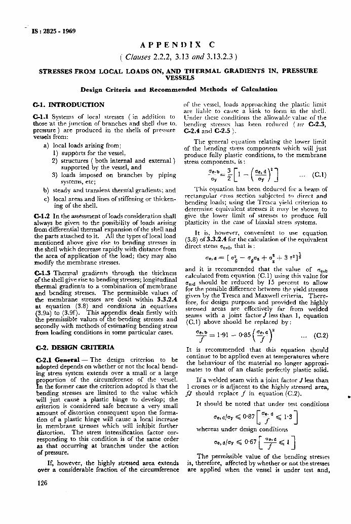
IS : 2825 - 1969
APPENDIX C
( Clauses 2.2.2, 3.13 and 3.13.2.3 )
STRESSES FROM LOCAL LOADS ON, AND THERMAL GRADIENTS VESSELS
C-l. INTRODUCTION
C-l.1 Systems of local stresses ( in addition to those ‘at the junction of branches and shell due to, pressure ) are produced in the shells of pressure vessels from:
a) local loads arising from; 1) suppbrts for the vessel,
2) structures ( both internal and external ) supported by the vessel, and
3) loads imposed on branches by piping systems, etc;
b) steady and transient thernial gradients; and c) local areas and lines of stiffening or thicken-
ing of the shell.
C-l.2 In the assessment of loads consideration shall always be given to the possibility of loads arising from differentia! thermal expansion of the shell and the parts attached to it. All the types of local load mentioned above give rise to bending stresses in the shell which decrease rapidly with distance from the area of application of the load; they may also modify the membrane stresses.
C-l.3 Thermal gradients through the thickness of the shell give rise to bending stresses; longitudinal thermal gradients to a combination of membrane and bending stresses. The permissible values of the membrane stresses are dealt within 3.3.2.4 at equation (3.8) and conditions in equations (3.9a) to (3.9f). This appendix deals firstly with the permissible values of the-bending stresses and secondly with methods of estimating bending stress from loading conditions in some particular cases.
C-2. DESIGN CRITERIA
C-2.1 General-The design criterion to be adopted depends on whether or not the local bend- ing stress system extends over a small or a large
21 roportion of the circumference of the vessel. n the former case the criterion adopted is that the
bending stresses are limited to the value which will just cause a plastic hinge to develop; the criterion is considered safe because a very small amount of distortion consequent upon the forma- tion of a plastic hinge will cause a local increase in membrane stresses which will inhibit further distortion. The stress intensification factor cor- responding to this condition is of the same order as that occurring at branches under the action of pressure.
If, however, the highly stressed area extends ovkr a considerable fraction of the circumference
IN, PRESSURE
of the vessel, loads approaching the plastic limit are liable to cause a kink to form in the shell. Under these conditions the allowablc value of the bending stresses has been reduced ( see C-2.3, C-2.4 and C-2.5 ).
The general equation relating the lower limit of the ljending stress components which will just produce fully plastic conditions, to the membrane stress components, is :
<!L ;[I _ (y>‘3 ...
Design Criteria axed Recommended Methods of Calculation
(C-1)
This equation has been deduced for a beam of rectangular cross section subjected to direct and bending loads; using the Tresca yield criterion to determine equivalent stresses it may he shown to give the lower limit of stresses to produce full plasticity in the case of biaxial stress systems.
It is, however, convenient to use equation (3.8) of 3.3.2.4 for the calculation of the equivalent direct stress a,,d, that is :
and it is recommended that the value of n,,,, calculated from equation (C.l) using this value for a,,d should be reduced by 15 percent to allow for the possible difference between the yield stresses given by the Tresca and Maxwell criteria. There- fore, for design purposes and provided the highly stressed areas are effectively &r from welded seams with a joint factor J less than 1, equation (C.1) above should be replaced by :
aej b - = 1.91 f
...
It is recommended that this equation should continue to be applied even at temperatures where the behaviour of the material no longer approxi- mates to that of an elastic perfectly plastic solid.
If a welded seam with a joint factor J less than 1 crosses or is adjacent to the highly stressed area,
fJ should replace f in equation (C.2).
It should be noted that under test conditions
3 whereas under design conditions
The permissible value of the bending stresses is, therefore, affected by whether or not the stresses are applied when the vessel is under test and,
126
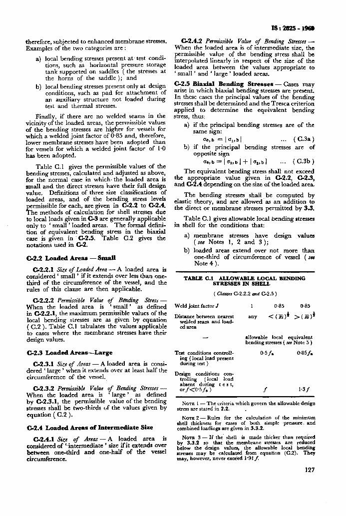
IS:282511968
G2.4.2 Permissible Value of Bending Stresses - When the loaded area is of intermediate size, the permissible value of the bending stress shall be interpolated linearly in respect of the size of the loaded area between the values appropriate to ‘ small ’ and ‘ large ’ loaded areas.
C-2.5 Biaxial Bending Stresses - Cases may arise in which biaxial bending stresses are present. In these cases the principal values of the bending stresses shall be determined and the Tresca criterion applied to determine the equivalent bending stress, thus:
a) if the principal bending stresses are of the same sign:
Qe, b = 1 ‘Jpb 1 . . . ( C.3a)
b) if the principal bending stresses are of opposite sign
Ue,b = l%bi+ I%bj . . . (C.3b)
The equivalent bending stress shall not exceed the appropriate value given in C-2.2, G2.3, and G2.4 depending on the size of the loaded area.
The bending stresses shall be computed by elastic thtory, and are allowed as an addition to the direct or membrane stresses permitted by 3.3.
Table C.l gives allowable local bending stresses in shell for the conditions that:
a) membrane stresses have design values (see Notes 1, 2 and 3);
b) loaded areas extend over not more than one-third of circumference of vessel ( su Note 4 ).
therefore, subjected to enhanced membrane stresses. Examples of the two categories are :
4
b)
local bending stresses present at 1 test condi- tions, such as horizontal pressure storage tank sapported on saddles ( the stresses at the horns of the saddle ) ; and
local bending stresses present Only at design conditions, such as pad for attachment of an auxiliary structure not loaded during test and thermal stresses.
Finally, if there are no welded seams in the vicinity of the loaded areas, the permissible values of the bending stresses are higher for vessels for which a welded joint factor of 0*85 and, therefore, lower membrane stresses have been adopted than for vessels for which a welded joint factor of 1.0 has been adopted.
Table C.1 gives the permissible values of the bending stresses, calculated and adjusted as above, for the normal case in which’ the loaded area is small and the direct stresses have their full design value. Definitions of three size classifications of loaded areas, and of the bending stress levels
ermissible for each, are given in C-2.2 to 6.4. % he methods of calculation for shell stresses due to local loads given in C-3 are generally applicable only to ‘ small ’ loaded areas. The formal defini- tion of .equivalent bending stress in the biaxial case is given in C-2.5. Table C.2 gives the notations used in G2.
C-2.2 Loaded Areas - Small
G2.2.1 Size of Loaded Area - A loaded area is considered ‘ small ’ if it extends over less than one- third of the circumference of the vessel, and the rules of this clause are then applicable.
6.2.2 Permissible Value of Baading Stress - When the loaded area is ‘ small ’ as defined in C-2.2.1, the maximum permissible values of the local bending stresses are as given by equation ( C.2 ). Table C.l tabulates the values applicable to cases where the membrane stresses have their design values.
C-2.3 Loaded Areas-Large
C-2.3.1 Size of Areas - A loaded area is consi- dered ‘ large ’ when it extends over at least half the circumference of the vessel.
G2.3.2 Permissible Value of Bending Stresses - When the loaded area is ‘ large ’ as defined by G2.3.1, the permissible value of the bending stresses shall be two-thirds tif the values given by equation ( C.2 ).
6.4 Loaded Areas of Intermediate Size
C-2.4.1 Ske of Areas-A loaded area is considered of ‘intermediate ’ size if it extends over between one-third and one-half of the vessel circumference.
TABLB C.1 ALLOWABLE LOCAL BENDING STRESSES IN SHELL
( Clauses C-2.2.2 and G2.5 )
Weld joint factor J 1 045 0.85
Distance between nearert welded scam and load- ed area
any < (2)) >(Bi))
- allowable local equivalent bending stresses ( scc Note 5 )
Test conditions controll- ing (local load present during test )
0.5f. 043.5 f.
Design conditions con- trolling (local load absent during test, orf<0’5f s 1 f 1.3f
NOTE I- The criteria which govern the allowable design stress are stated in 2.2. .
NOTE 2 -Rules for the calculation of the minimum shell thickness for cases of both simple pressure. and combined loadinga are given in 3.3.2.
NOTE 3 - If the shell is made thicker than reauired by 3.3.2 so that tbe membrane stresses are re&ced below the design values, the allowable local bending strescs may be calculated from equation (C.2). They may, however, never exctied 1.91 f.
!27
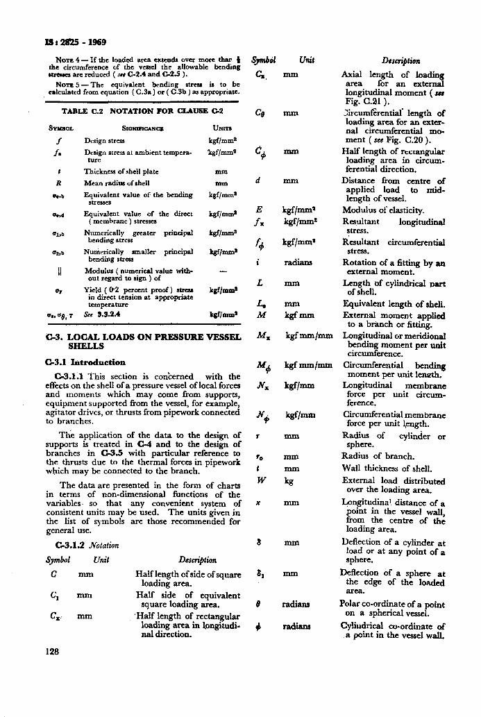
lSr28!25-1969
Non 4 - If the loadcd area extcnda over more than t the circumference of the vessel the allowable bending rtnues arc reduced ( see C-2.4 and 02.5 ).
NOTE 5 -The equivalent bending stress is to be calculated from equation ( C.3a ) or ( C.3b J as appropriate.
TABLE C.2 NOTATION FOR CIAUSE C&2
SYMBOL
f
f.
:
R
0e.b
%b
Q8.b
II
or
Design stress
Design stress at ambient tempera- ture
Thickness of shell plate
Mean radius of shell
Equivalent value of the bending stresses
Equivalent value of the direct ( memhrane ) stresses
Numerically greater principal bending stress
Numerically smaller principal bending stress
Modulus ( numerical value witb- out regard to sign ) of
Yield ( W2 percent proof) stress in direct tension at appropriate temperature
See 5.3.2.4
UNITS
kgf/mms
kgflmms
mm
mm
kgf/mms
Irgfbms
kgf/mms
k&mm4
-
kgf/mms
kgfbm’
C-3. LOCAL LOADS ON PRESSURE VESSEL SHELLS
C-3.1 Introduction
G3.1;1 This section is con’cerned with the effects on the shell of a pressure vessel of local forces and moments which may come from supports, equipment supported from the vessel, for example, agitator drives, or thrusts from pipework connected to branches.
Thk application of the data to the design of supports is treated in C-4 and to the design of branches in C-3.5 with particular reference to the thrusts due to the thermal forces in pipework which may be connected to the branch.
The data are presented in the form of charts in terms of non-dimensional functions of the variables. so that any convenient system of consistent units may be used. The units given in the list of symbols are those recommended for general use.
G3.1.2 Notation
Symbol Unit
c mm
CI -
C, mm
Descripian
Half length of side of square loading area.
Half side of equivalent square loading area.
.Half length of rectangular loading area in longitudi- nal direction.
128
Sjdtil Unit
mm
mm
mm
mm
kgf/mm
mm
mm
-
kg
mm
mm
-
radians
radians
Desc+tioa
Axial length of loading area for an external longitudinal moment ( se8 Fig. C.21-).
Zircumf&ential* length of loading area for an exter- nal circumferential mo- ment ( see Fig. C.20 ).
Half length of rtctangular loading area in circum- ferential direction.
Distance from centre of applied load to mid- length of vessel.
Modulus of elasticity.
Resultant longitudinal stress.
Resultant circumferential stress.
Rotation of a fitting by an external moment.
Length of cylindiical part of shell.
Equivalent length of shell.
External moment applied to a branch or fitting.
Longitudinal or meridional bending moment per unit circumference.
Circumferential bending moment per unit lencth.
Longitudinal membrane force per unit circum- ference.
Circumferential membrane force per unit Jength.
ypteye of cylinder or .
Radius of branch.
Wall thickness of shell.
External load distributed over the loading area.
Lpngitudina! distance of a point in the vessel wall, from the centre of the loading area.
Deflection of a cylinder at load or at any point of a sphere.
Deflection of a sphere at the edge of the loaded area.
Polar co-ordinate of a point on a spherical vessel.
Cyliudrical co-ordinate of a point in the vessel wall.
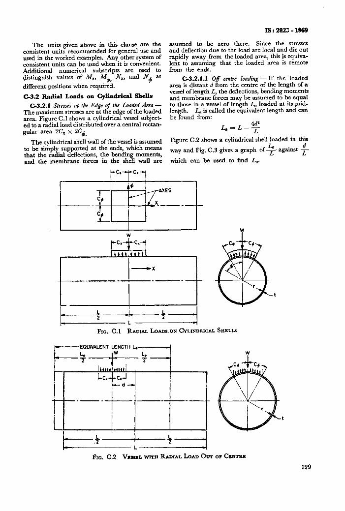
The units given above in this clause are the consistent units recommended for general use and used in the worked examples. Any other system of consistent units can be used when it is convenient. Additional numerical subscripts are used to distinguish values of Mx, M+, IV,, and Jv+ at
different positions when required.
C-3.2 Radial Loads on Cylindrical Shells
C-3.2.1 Stresses at the Edge of the Loaded Area - The maximum stresses are at the edge of the loaded area. Figure C.l shows a cylindrical vessel subject- ed to a radial load distributed over a central rectan- gular area 2C, x 254.
The cylindrical shell wall of the vessel is assumed to be simply supported at the ends, which means that the radial deflections, the bending moments, and the membrane forces in the shell wall are
IS : 282: - 1969
assumed to be zero there. Since the stresses and deflection due to the load are local and die out rapidly away from the loaded area, this is equiva- lent to assuming that the loaded area is remote from the ends.
C-3.2.1.1 Of centre loading - If the loaded area is distant d from the centre of the length of a vessel of length L, the deflections, bending moments and membrane forces may be assumed to be equal to those in a vessel of length L, loaded at its pid- length. L, is called the equivalent length and can be found from:
ad= LyL-y
Figure C.2 shows a cylindrical shell loaded in this
way and Fig. C.3 gives a graph of 2 d
against - L
which can be used to find LB.
FIG C.l RADIAL LOADS ON CYLINDRICAL SHELLS
~-EQUIVALENT LENGTH Lc+
FIG. C.2 VE~SSSLWITH RADIAL LOAD OUT OF CENTRE
129
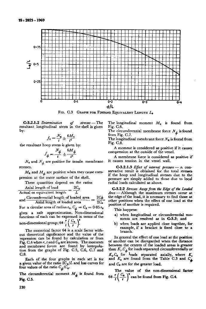
d/L FIG. C.3 GRAPH FOR FINDING EQUIVALENT LENGTH Le
C-3.2.1.2 Determination of strenes - The resultant longitudinal stress in the shell is given by:
fx=~*!z?$
the resultant hoop stress is given by:
+ 6M+ f+=-i_ f7
N, and Jv+ are positive for tensile membrane
stresses.
Mx and M+ are positive when they cause com-
pression at the outer surface of the shell.
These quantities depend on the ratios
Axial length of load 2CX Actual or equivalent length = z
and Circumferential length of loaded area 2c+ Axial length of loaded area =2cx
For a circular area of radius r,,, C+ = C, = 0435 r,,
a safe approximation. Non-dimensional ETtions of each can be expressed in terms of the
non-dimensional group; 64 f 2 .
The numerical factor 64 is a scale factor with- out theoretical significance and the value of the xpression can be found by calculation or from Fig. C.4 when r, t and C, are known. The moments and membrane forces are found by interpola- tion from the graphs of Fig. C.5, C.6, C.7 and C.8.
Each of the four graphs in each set is for a given value of the ratio 2&/L and has curves for four values of the ratio C+/C,.
The circumferential moment Md. is found from
Fig. C.5.
130
The longitudinal moment MX is found from. Fig. C.6. The circumferential membrane force &
+ is found.
from Fig. C.7. The longitudinal membrane force .JV, is found from Fig. C.8.
A moment is considered as positive if it causes compression at the outside of the vessel.
A membrane force is considered as positive if it causes tension in the vessel wall.
C-3.2.1.3 E$ect of internal pressure -A con- servative result is obtained for the total stresses if the hoop and longitudinal stresses due to the pressure are simply added to those due to local radial loads calculated as above.
C-3.2.2 Stresses Away3om the Edge of the Lo&d Area-Although the maximum stresses occur at the edge of the load, it is necessary to find those at other positions when the effect of one load at the position of another is required.
This happens:
a) when longitudinal or circumferential mo- ments are resolved as in G3.3; and
‘b) when loads are applied close together, for example, if a bracket is fixed close to a branch.
In general the effect of one load at the position ot’ another can be disregarded when the distance between the centres of the loaded areas is greater than K,.C+ for loads separated circumferentially or’
K,.C, for bads separated axially, where Kr and X2 are found from the Table C.3 and C
and C, are for the greater load. +
The value of the non-dimensional factor
64f can be found from Fig. C.4.
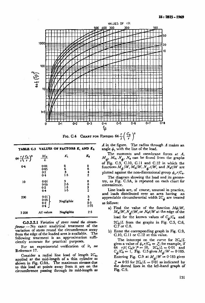
VALUES OF r/t
IS:2925-1969
%
Fxo. C.4 CHART FOR FINDING 64 f
TABLE C.3 VAIN= OF FACTORS Kt AND K,
0.4 O-01 8 8 O-05 6 8
8:; l-5 3 :
10 O-01 0.05 f.: k! 0.2 . 3 0.4 1.5 2
200 Negligible 5
2.5 l-75
3200 All values Negligible 2’5
C-3.2.2.1 Variation of stress round the circum- fncmc - No exact analytical treatment of the variation of stress round the circumference away from the edge of the loaded area is available. The following treatment is an approximation suffi- ciently accurate for practical purposes.
For an experimental verification of it, see Reference 17.
Consider a radial line load of length 2C,, applied at the mid-length of a thin cylinder as shown in Fig. C.9A. The maximum stresses due to this load at points away from it are on the circumference passing through its mid-length as
A in the figure. The radius through A makes an angle +r with the line of the load.
The moments and membrane forces at A, M+, M,, N+, Jv, can be found from the graphs
of Fig. C.9, C.10, C.ll and C.12 in which the functions M+/ W, M,I W, N+.t/ W, and Nxt/ W are
plotted against the non-dimensional group +,.r/C,. The diagram showing the load and its geome-
try, as Fig. C.9A, is repeated on each chart for convenience.
Line loads are, of course, unusual in practice, and loads distributed over an area having an appreciable circumferential width 2C are treated
4 as follows:
4
b)
Find the value of the function M+/ W, MxIWJ$tIW,. or .hLtl W at the edge of the
load for the known values of C+/C, and
2&/L from the graphs in Fig. C.5, C.6, C.7 or C.8. Enter the corresponding graph in Fig. C.9, C.10, C.11 or C.12 at this value.
The intercept on the curve for 2C;lL gives a value of #r.r/C, = 5; for example, if 64 r/t( G/r ).* = 10, 2CJL = 0.01 and C,/Cx =1 1, Frg. C.5 gives M+/W = O-185.
Entering Fig. C.9 at M /W = O-185 gives ,+
5 = O-55 for 2&/L = 0.01 as indicated by the dotted lines in the left-hand graph of Fig. C.9.
131
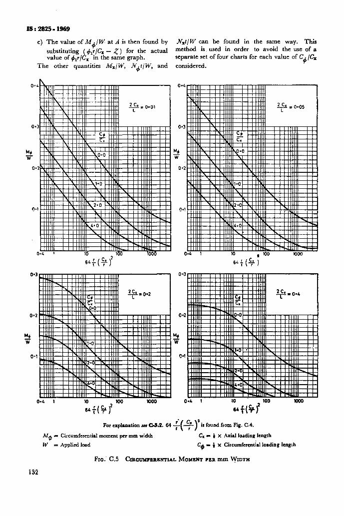
IS:2825-1969
c) The value of M+/ W at A is then found by N=t/ W can be found in the same way. This
substituting ( &/C, - 5) for the actual method is used in order to avoid the use of a
value of 41r/Cx in the same graph.
The other quantities MxjW,
separate set of four charts for each value of C+ /C,
N+t/W, and considered.
0.2
M+ F
0.1
0*4 1 l0 100 1000
O-4
0*3
M* F
o-2
O*l
0P-T 10 a 100 1000
For explanation SW C-3.2. 64 t(+)’ is found from Fig. C-4.
Ma = Circumferential moment per mm width Cx - 4 x Axial loading length
W = Applied load C$ - 4 x Circumferential loading length
Fro. C.5 CIRCUMFERENTIAL MOMENT PER mm WIDTH
132
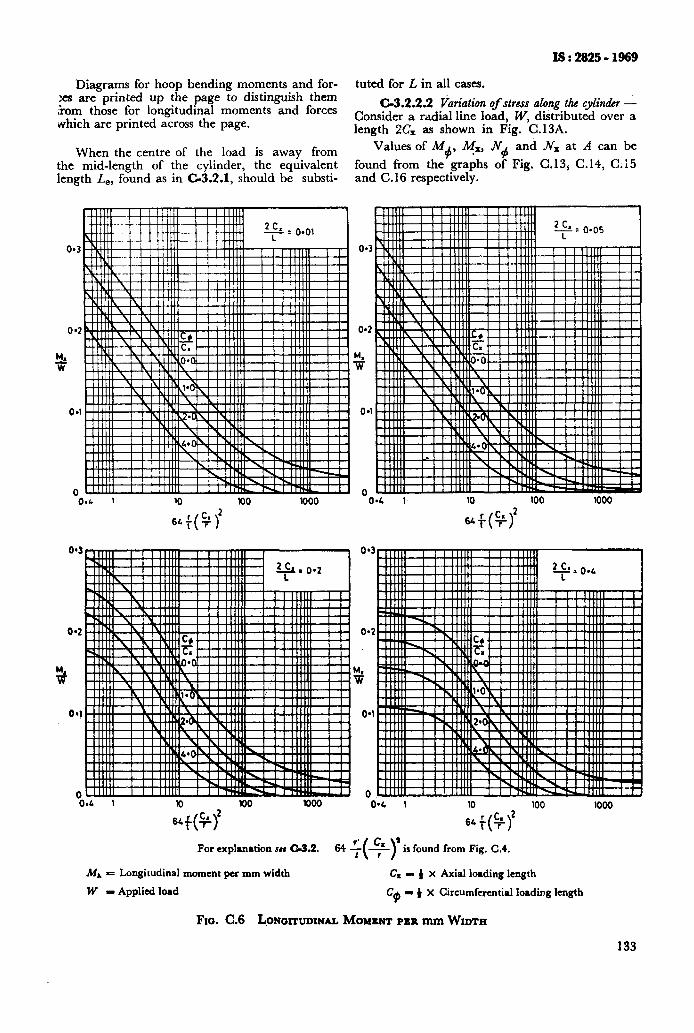
IS : 2825 - 1969
Diagrams for hoop bending moments and for- tuted for L in all cases. :es are printed up the page to distinguish them Tram those for longitudinal moments and forces
C-3.2.2.2 Variation of stress along the cylinder -
which are printed across the page. Consider a radial line load, W, distributed over a length !-XT, as shown in Fig. C. 13A.
When the centre of the load is away from Values of M 4’
TX, .X and Nx at A can be
the mid-length of the cylinder, the equivalent found from the graphs of Fig. C.135 C. 14, C. 15 length L,, found as in C-3.2.1, should be substi- and C.16 respectively.
n
0.3
0*2 O*?
3
O*l
0 0 o*c 1 Kl 100 IO00 c
64#
-0.4 1 10 100 IO00
64+(g)2
84 1
1: f(4)’
100 1000
For explanation set 03.2. 1s found from Fig. C.4.
MA = Longitudinal moment pes mm width C. = 4 X Axial loading length
W - Applied load C$ - 4 X Circumferential loading length
Fxo. C.6 LONOI~UDINAL MOMENT PER mm WIDTH
133
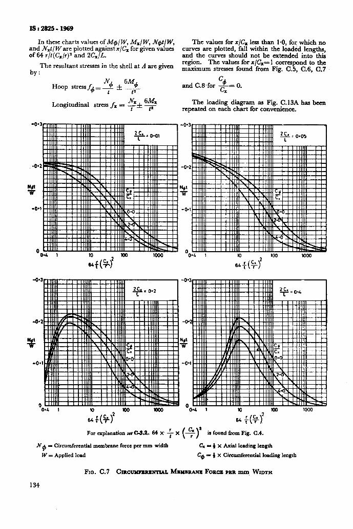
IS : 2825 - 1969
In these charts values of MeI W, Mx/ W, Net/W, and .Nxt/ W are plotted against x/C, for given values of 64 r/t(Cx/r)2 and 2&/L.
The resultant stresses in the shell at A are given by :
Hoop stress f+ = $! f ?!$_
Longitudinal stress fx =
-0.4 1
Z,(# loo loo0
The values for x/C, less than 1.0, for which no curves are plotted, fall within the loaded lengths, and the curves should not be extended into this region. The values for x/C&= 1 correspond to the maximum stresses found from Fig. C.5, C.6, C.7
c# and C.8.for -= 0. G
The loading diagram as Fig. C.13A has been repeated on each chart for convenience.
-0’4 1 10 100
wf(# 1000
-0.4 1 lo loo low
64 C(9)’ For explanation sea c&g.. 64 X fX
Ng, = Circumferential membrane force per mm width
W = Applied load
is found from Fig. C.4.
C. = 4 X Axial larding length
Ce - 4 X Circumferential loading length
FIO. C.,7 CIR~~MP~RENTIA~ MEMBRANE FORCE PBR mm, WIDTH
134
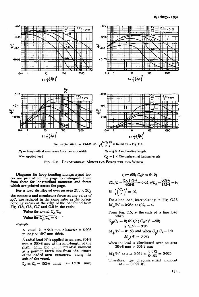
ISt2825=1!M9
w4 1 10 w WOO O-4 1 10 IO0 'Km0
64+&f 64+&f
O-15 %
O-1
0*05
0*4 1 IO lo0' m0
For explanation see C-3.2. 64 + is found from Fig. C.4.
.& = Longitudinal membrane force’pcr mni width C= = + X Axial loading length
W = Applied load Ce = ) x Circumferential loading length
Fro. C.8 LONQITUDINAL MEMBRANE FORCE PER mm WIDTH
Diagrams for hoop bending moments and for- ces are printed up the page to distinguish them from those for longitudinal moments and forces which are printed across the page.
For a load distributed over an area 2Cx x 2C+
the moments and membrane forces at any value of x/C, are reduced in the same ratio as the corres- ponding values at the edge of the load found from Fig. C.5, C.6, C.7 and C.8 in the ratio:
Value for actual C+/C,
-V&G-fo~+/cx = o-’
Example:
A vessel is 2 540 mm diameter x 6.096 m long x 12.7 mm thick.
A-radial load W is applied to an area 304.8 mm x 3W8 mm at the mid-length of the shell. Find the circumferential moment at a position 609.6 mm from the centre ‘of the loaded area measured along the axis of the vessel.
Cd = c, = 152.4 mm; r= 1270 mm;
r/r=m; C& = o-12;
’ = 90.
For a line load, interpolating in Fig. C.13
M&W = O-054 at x/Cx = 4.
From Fig. C.5, at the ends of a line load when
C+lc, = 0; 64 r/t ( C,/r )” -90;
2 C,/L = 0.05 M+/ W = O-153 and when C+/ C,= I.0
M4/W 1 0.072
when the load is distributed over an area 304.8 mm x 304.8 mm
M+/W atx=O.O54xE=
Therefore, the circumferential at x = 0.025 W.
O-025
moment
135
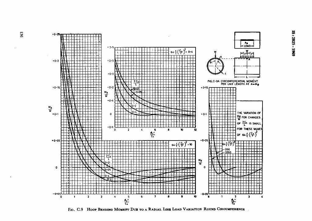
i
W C ___ -_ _ f!!TFt --I- t
I-L---WI
FIG.C-9A CIRCUMFERENTIAL MOMiN PER UNIT LENGTH AT A-M+
THE VARIATION OF
2 FOR CHANGES
OF + IS SMALL
+o*os
t-44 w
0
-0.05- 0 1 2 3 4 5 6 7 9 9 lo 0
tc C.
FIG. C.9 HOOP BENDING MOMENT DUE TO A RADIAL LIP LOAD VARXATION ROUND CIRCUYPERENCE
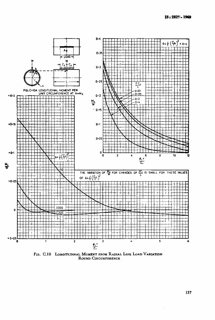
W
El? A=M,,
O-35
0.3
0.25
0*2
M. w
. 0.15
0.1
C! ! ! ! !\. ! ! ! ! IY! ! ! ! ! ! ! ! ! ! ! ! I
FIG.C-1OA LONGITUDINAL MOMENT F
l 0*2 UNIT CIRCUMFERENCE Al
0 2 4 6 10 12 $1 r c.
-0405 0 1 2 3 L 5 6
92 C*
FIG. C.10 LONQITUDINAL MOMENT FROM RADIAL LINE LOAD VARIATION ROUND CIRCUMFERENCE
137
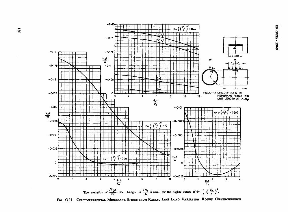
FIG.C-1IA ClRCUidFERENTlAC MEMBRANE FORCE PER UNIT LENGTH AT A=N#
Net The variation of 7 for changed in F ir amdl for the higher values of 64 f py.
FIG. C.11 CIRCUMPERBNTIAL MEMBRANE STRBSS PROM RADIAL LINE LOAD VARIATION ROUND CIRCUMFERENCE
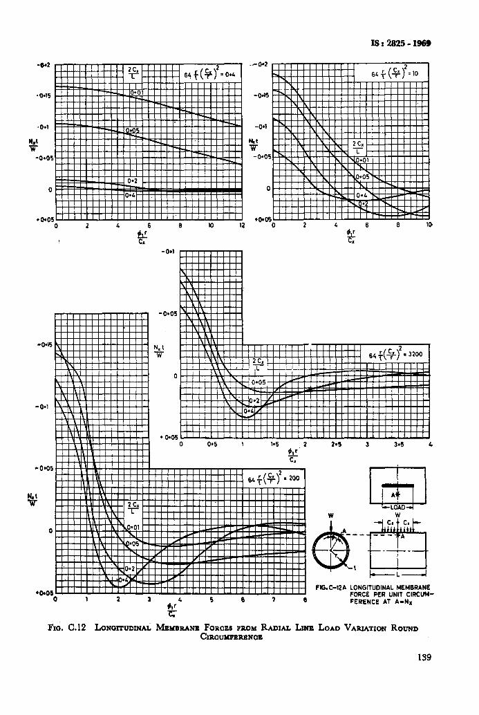
IS t 2825 - 1969
-6-2 Illll III III
2~. rllll -r ! ( ! ( ( 6#q2=0.L
_ _- 0 2 4 6
-0.15
-0.1
-0*05
v
0
‘bO6
- 0.1
6 10 12
I I
.-0.2
-0.15
-04
hht w
-0*05
0
to*06 _ -_ 0 2 4 6 6 10
0 1 2 3
Fm. C.12 LONOITUDINA~
N. t Ti
0
l 0905
#,r4 5 6 7 6
c-
2.5 3 3*5 4
w W
F&C-12A LONGITUDINAL MEMBRANE FORCE PER UNIT CIRCUM- FERENCE AT A-NM
MEMBUNB FOrtOE PROM RADIAL LYE LOAD VARUTKW ROUND CIRaubmaaNaE
159
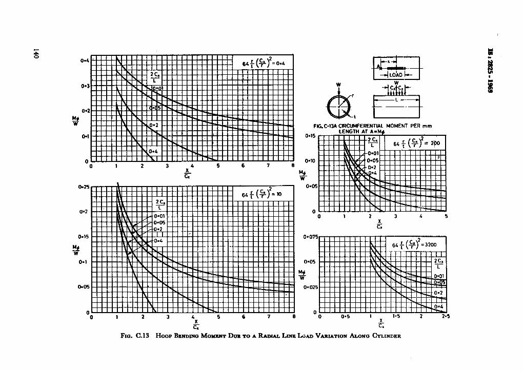
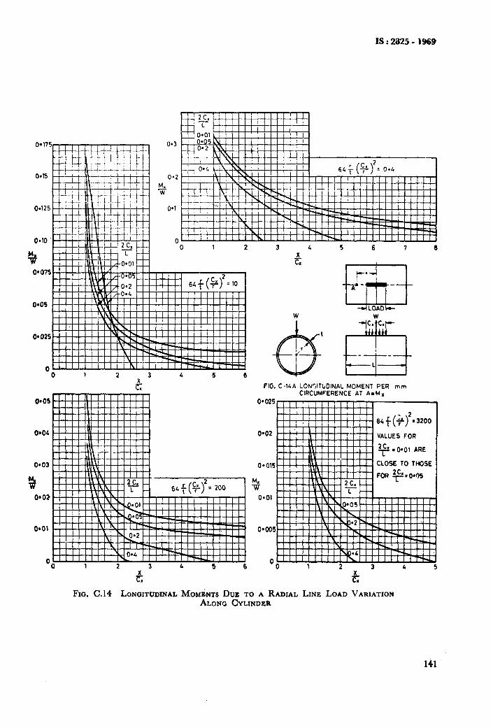
IS:2825-1969
0.125
0e10 w-i4-1
0*3
o-2
!s W
0.1
0 0 1 2 3 4 5 6 7 6
-0 1 2 3 5 6
c
FIG. CGA LONVTUOINAL MOMENT PER mm CIRCUMFERENCE AT A=Mx
0.025
o-02 VALUES FOR
y so.01 ARE
CLOSE TO THOSE 0.015
%
0.01
G G Fro. C.14 LONOITUDINAL MOMENTS DUE TO A RADIAL LINE LOAD VARIATION
ALQNC CYLINDER
141
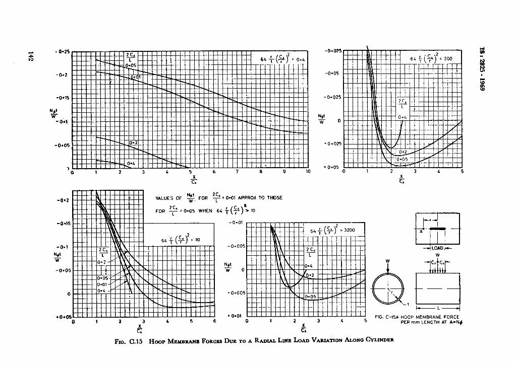
- 0.2
-0915
H*t w
-Oil\
-m05
1 0 1 2 3 5 6 7 8 9 10
2
0 1 2 3 5 6
G
-0.05
- 0.025
NP w 0
0.01 APPROX TO THOSE
;(+qia 10
------I FIG. C-15A HOOP MEMBRANE FORCE
PER mm ?ENGTH AT A.=N$
Fro. C.15 H~~PMEMBRANBFORCES DUE TO A RADIALLINE LOAD VARIATIONAL~N~CYLINDER
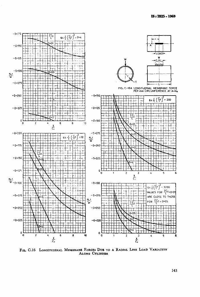
-0.75
- 0.150
-0.125
- O*lOO N,l -W-
-0.075
-0.050
- 0*025
0 .O 2 4 6 e la
X cY
-0-200
-0*!75
-0.125
-0.025
“0 2 4 6 8 1C
FIG. C-16A LONGITUDINAL MEMBRANE FORCE PER mm CIRCUMFERENCE AT A=Nn
-0.125
- 0 l lOO
-3.075
$J W
-0~050
-9.025
0 0 1 2 3 4 5 6
x_ CT
;OR 2c.=O.O, I
I 0 1 2 3 4 5 6
FIG. C.16 LONGITUDINAL MEMBRANE FORCES DUE TO A RADIAL LINE LOAD VARIATION ALONO CYLINDBR
143
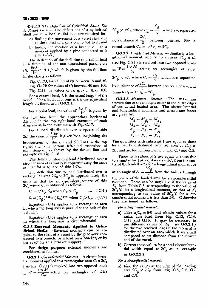
IS : 2825 - 1969
C-3.2.3 The DeJIectiorrs of Cylindrical Shells Due to Radial Loads - The deflections of a cylindrical shell due to a local radial !oad are required for:
a) finding the movement of a vessei shell due to the thrust of a pipe connected to it, and
b) finding the rotation of a branch due to a moment applied by a pipe connected to it ( see C-3.3 j.
The deflection of the shell due to a radial load is a function of the non-dimensional parameters
ErB r/t, 7 and L/r which is given by the full lines
in the charts as follows:
Fig. C.17A for values of r/t between 15 and 40. Fig. C. 17B for values of r/t between 40 and 100. Fig. C.18 for values of r/t greater than 100.
For a central load, L is the actual length of the vessel. For a load out of centre: L is the equivalent length Le found as in C-3.2.1.
E.r 8 For a point load, the value of7 is given by
the full line from the appropriate horizontal L/r line in ‘the top right-hand extension of each diagram as. in the example with Fig. C.17.
For a ioad distributed over a square of side 8 l?r
32, the value of - W
is given by a line joining the
intersections of the L/r and C/r lines in the top right-hand and bottom left-hand extensions of each diagram as shown by the dotted line and example on Fig. C.18.
The deflection due to a load distributed over a circular area of radius r,, is approximately the same as that for a square of side 1*7ro.
The deflection due to load distributed eve* a rectangular area 2C, x 2C
4 is approximately the
same as that for an equivalent_ square of side 2Cr where C, is obtained asfollows:
C, =dC+ &when Ci > C+ . . . (C.4)
Cr=(C,, woax (C,)O’Or when C+>&... (C.5)
Equation (C.4) applies to a rectangular area in which the long axis is parallel to the axis of the cylinder.
Equation (C.5) applies to a rectangular area in which the long axis is circumferential.
C-3.3 External Moments Applied to Cylb- drical Shells - External moments can be ap- plied to the shell of a vessel by the pipework con- nected to a branch, by a load on a bracket, or by the reaction at a bracket support.
For design purposes external moments are considered as follows.
C-3.3.1 Circumferential Moments-A circumferen- tial moment applied to a rectangular area Co x 2C,
( see Fig. C.20 ) is resolved into two opposed loads
f W = y acting on rectangles of sides
144
2C x 2C,, where C %
d 4 6’ = - which are separated
2CQ by a distance of -3-- between centres. For a
round branch Ce = l-7 r,, = 2Cx.
C-3.3.2 Longitudinal Moments - Similarly a lon- gitudinal moment, applied to an area 2C+ x C,
( see Fig. C.21 ) is resolved into two opposed loads 1.5 M
fW=7 acting on rectangles of sides z
C 2C+ x 2C, where C, = $’ , which are separated
by a distance of% between centres. For a round
branch C, = 1*7r,, = 2C +*
C-3.3.3 M&mum Stresses - The maximum stresses due to the moment occur at the outer edges of the actual loaded area. The circumferential and longitudinal moments and membrane forces are given by:
M4 M = M+ -M
1 dz x = 1% - Mxz
N+ = N& - Jv+
Jvx = .G, - jY,:
The quantities with subscript 1 are equal to those for a load 14’ distributed over an area of 2C4 x
2C, and are found from Fig. C.5, C.6, C.7 and C.8.
Those with subscript 2 are equal to those due to a similar load at a distance x=-5& from the cen- tre of the loaded area for a longitudinal moment or
5c 9 at an angle of 4, = r from the radius through
the centre of the loaded area for a circumferential moment. These can be neglected if the value of K,, from Table C.3, corresponding to the value of 2&/L for a longitudinal moment, or that of Kr corresponding to the value of 2&/L for a cir- cumferential moment, is less than 5.0. Otherwise they are found as follows:
For a longitudinal moment:
4
W
Take x/C, = 5.0 and obtain values for a radial line load from Fig. C. 13, C. 14, C.15 and C.16. It may be necessary to use different values of LI ( see c3.2.1) for the. two resolved loads if the moment is distributed over an area which is not small compared to its distance from the nearer end of the vessel.
Correct these values for a total circumferen- tial width equal to 2C
4 as in example
in C-3.2.2.2.
For a circumf~ential moment:
a) Find the values at the edge of the loading area 2C+ x 2C, from Fig. C.5, C.6, C.7
and C.8.
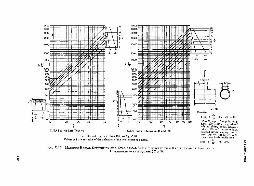
7000
6000
clK)n
.V”_
900 800 700
600
7000
6000
5000
P .__ 15 20 25 30 40
r i
C.17A For r/t Less Than 40
c. 17c
&amble:
2 -10 4-d on ” 1000 Find fjEI w
80 90 100 r/t = 70, c/r i r Enter L/r = ; UI. OIL 40 50 60 70
B i
C.17B For r/t Between 40 and 100
For values of r/t greater than 100, scc Fig. C.18. Values of 8 are exclusive of the deflection of the whole shell as a beam.
for L/r = 10,
= 0 = point load. 10 at right-hand
side of chart, move “ho&-on_ tally to C/r = 0 or point load, proceed down sloping line 10 meet vertical line for r/t = 70, then move horizontally and
read 6 k=17 000. W
FIG. C.17 MAXIMUM RADIAL DEFLECTION OF A CYLINDRICAL SHELL SUBJECTED TO A RADIAL LOAD W UNIFORMLY DISTRIBUTED OVER A SQUARE 2C x 2C
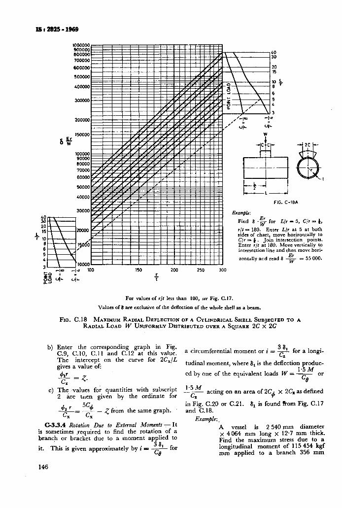
1000000 900000 600000 700000
600000
500000
400000
3OoOOO
200000
150000
100000 90000 80000
70000
60000
200 250 300
146
FIG. C-16A
Example: Er
Find 8 7 for L/r = 5, C/r = 4,
r/t = 180. Enter L/r at 5 at both sides of chart, move horizontally to C/r = 4. Join intersection points. Enter r/t at 180. Move vertically to intersection line and then move hori-
zontally and read 6 G = 55 000.
For values of r/t less than 100, JCC Fig. C.17.
Values of El are exclusive of the deflection of the whole shell as a beam.
FIG. C.18 MAXIMUM RADIAL DEFLECTION OF A CYLINDRICAL SHELL SUBJECTED TO A RADIAL LOAD W UNIFORMLY DISTRIBUTED OVER A SQUARE 2C x 2C
Enter the corresponding graph in Fig. C.9, C.10, C.11 and C.12 at this value. The intercept on the curve for 2CxlL gives a value of:
&I_ = #7_
The values for quantities with subscript 2 are tuen given by the ordinate for
41 f % -=_-_- z from the same graph. LX t.i, -
C-3.3.4 Rotation Due to External Moments -Y- It is sometimes required to find the rotation of a branch or bracket due to a moment applied to
it. This is given approximately by i = - 3 ‘t for Ce
a circumferential moment or i = 38 --!_ for a longi- CZ
tudinal moment, where 6, is the deflection produc- 1.5 M
ed by one of the equivalent loads W = - Ct?
or
1.5M
G acting on an area of 2C$ x 2C, as defined
in Fig. C.20 or C.21. 6, is found R-om Fig. C. 17 and C.18.
Example:.
A vessel is 2 540 mm diameter x 4 064 mm long x 12.7 mm thick. Find the maximum stress due to a longitudinal moment of 115 454 kgf mm applied to a branch 356 mm
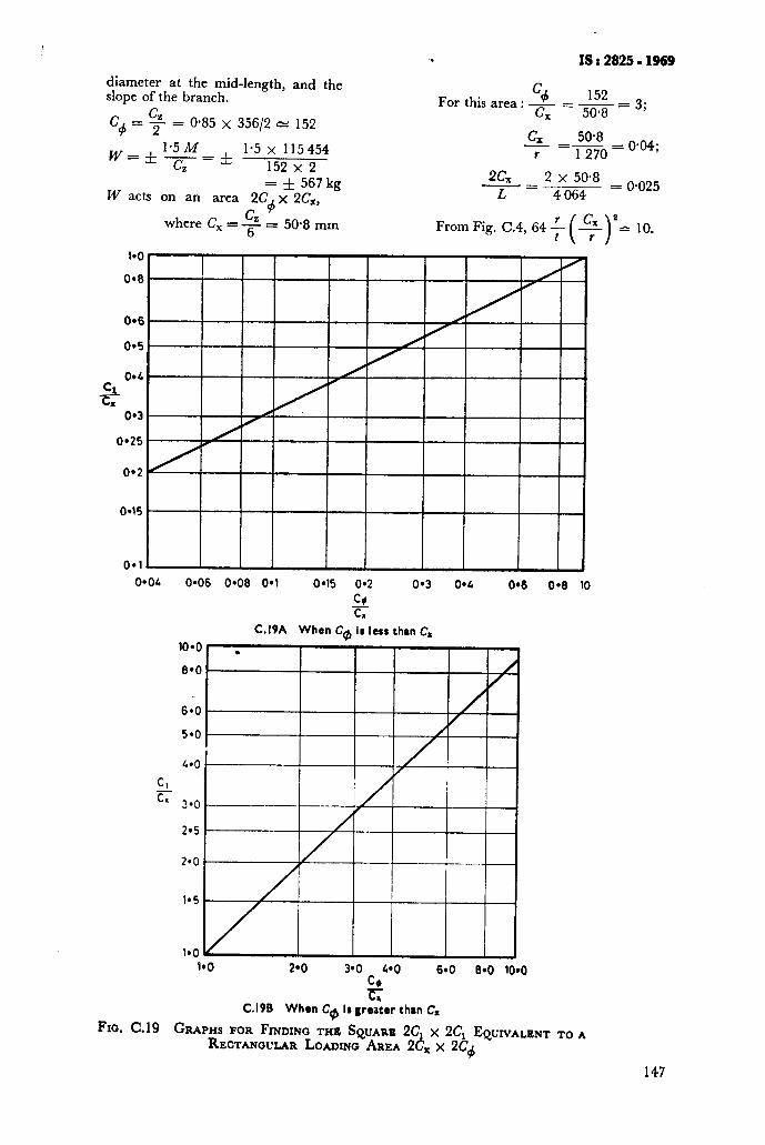
.‘i IS : 2825 - 1969
diameter at the mid-length, and the slope of the branch.
L?~ = $ = O-85 x 35612 c: 152
w= & 1*5/f_ * la5 n;:““; z
= f ‘567 kg W acts on an area 2C
4 x 2C,,
where C, = $. = 50.8 mm
% 152 For this area : c = - = 3; X 50.8
G 50.8 -=---_= r 1 270
0.04;
2G L
2 x 50’8 = 0.025 - =__------- 4 064
From Fig. C.4, 64 t
096
04
c& OgC
0.3
0.25
0.1
0*04 0.06 0.06 0.1 045 0*2 0.3 0.4 0.6 04 10
+f
4.0
Cl
c 3.0
2*5
. I*0 2.0 390 4’0
2
6aO 8*0 IO*0
C.IPB When Ca Is greater than C.
FIG. C.19 GRAPHS FOR FINDING THE SQUARE 2C, x 2C, EQUIVALENT TO A RECTANOUWR LOADING AREA 2Cx x 2C4
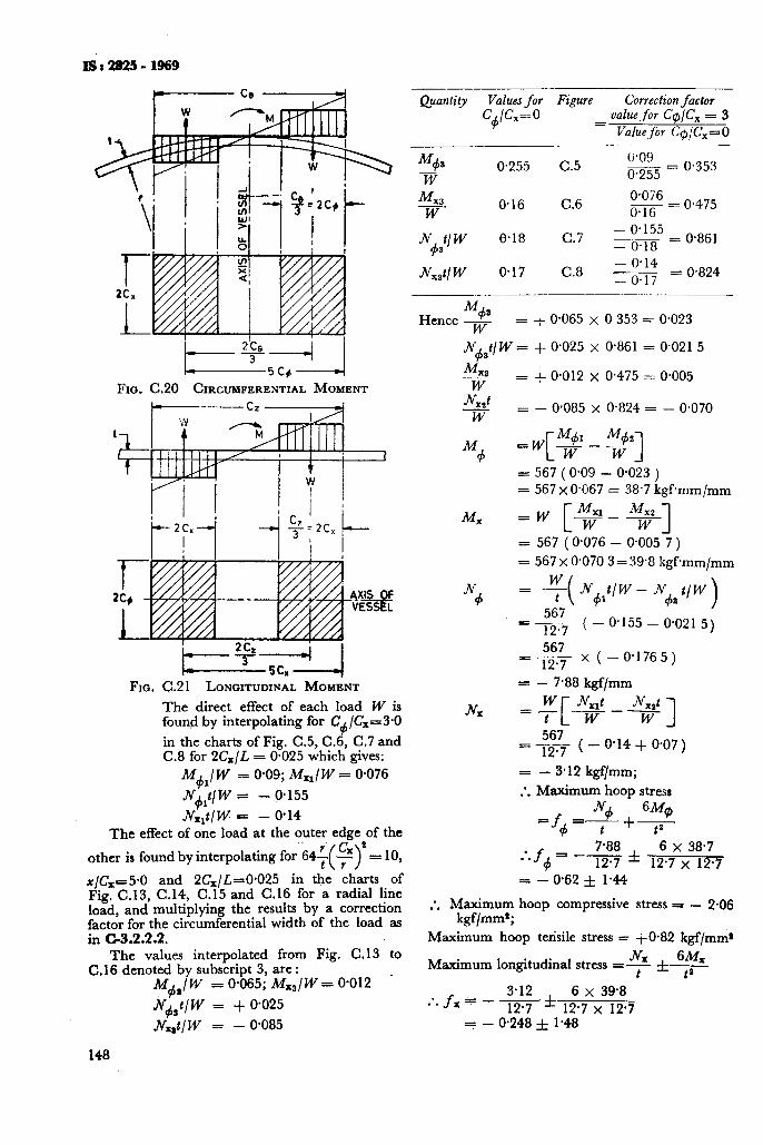
Quantity Values for Figure Correction factor c@= 0 = value_for C@jC, = 3
Vaahiefor C@/C,aO
I._.--*_A j I- - 5cg-4
FIG. C.20 CIRCUPFERENTIAL MOMENT
FIG. C.2 1 LONGITIJ~N~L MOMENT
The direct effect of each load W is found by interpolating for C+ /C,= 3.0
in the charts of Fig. C.5, C.6, C.7 and C.8 for 2&/L = 0.025 which gives:
M$J W - 0.09; MxJ W = 0.076
A&t/W = - 0,155
&t/W = - 0.14
The effect of one load at the outer edge of the r’
other is found by interpolating for 65 = 10,
x/&=5*0 and 2C,/L=O*O25 in the charts of Fig. C.13, C.14, C.15 and C.16 for a radial line load, and multiplying the results by a correction factor for the circumferential width of the load as in C-3.2.2.2.
The values interpolated from .Fig. C. 13 to C.16 denoted by subscript 3, are :
M$h/w = 0.065; Mx,/W = 0.012
N&/W = + 0.025
J&t/W = - 0.085
148
0.255 C.5 6.09 m55 = 0.353
x4 M 0.076 - = W
0.16 C.6 0.16
0.475
J$3” W 6.18 C.7 - o-155 ~ - 0.18 = 0.861
Jvxstl W 0.17 C.8 - 0.14 y = - 0.17
0.824
Hence M+s w = + 0.065 x 0 353 = 0.023
.Nd3t/ W = + 0.025 x 0.861 = 0.021 5
= + 0.012 x 0.475 = 0.005
= - 0,085 x 0.824 = - 0.070
=w w--w- C Mc+ M+ 1
= 567 ( 0.09 - 0.023 ) = 567 x 0.067 = 38.7 kgfmm/mm
=w +A!?$ [ 1
= 567 ( 0.076 - 0.005 7 ) = 567 x 0.070 3 = 39.8 kgfmm/mm
= q( Jv+t/w - J$ t/w >
= +& ( - 0.155 - 0.021 5)
567 “TX( - 0.1765)
= - 7.88 kgf/mm
w ~x,t Nx,t =_ --- t [ W 1 W_
= $4 ( - 0.14 + 0.07)
= - 3.12 kgf/mm;
’ Maximum hoop stress . . Jv+ - 6Mq)
-f4 =t +7
.‘.f4= -$$ f 6 x 38.7 12.7 x 12.7
= -0.62f 1.44
* Maximum hoop compressive stress = - 2.06 l ’ kgf/mms;
Maximum hoop tensile stress = +0*82 kgf/mms
6% Maximum longitudinal stress =% f,,
3.12 6 x 39.8 :. f. F - - * 12.7 12.7 x 12.7
=- 0.248 f 1.48
Maximum longitudina! -1.728 kgf/mnl”
Maximum longitudinal kgf/mm2
compressive stress =
tensile stress = + 1.232
Slope due to moment : For this area C IC, = 3, 4’
and from Fig. C.l9B, the half side of the equiva- lent square C, = 2*8C, = 2.8 x 50.8= 142 mm
In Fig. C.l7B, C,/Y 6 142/l 270 = 0.112; L/r = 4 064/l 270 = 3.2;
‘It = 1 270/12*7 = 100;
whence 6Erj W = 17 000
IO* x 567 :. 8,
1.7 x = -
2.04 x lo* x 1270 = 0.372 mm
and from C-3.3.4, the slope i = 36,
C7. 3 x 0.372 =
304.8
= 0.003 66 radians.
C-3.4 Local Loads on Spherical Shells
C-3.4.1 Initial Development - This clause is concerned with the stresses and deflections due to local radial loads or moments on spherical shells. Because these are local in character and die out rapidly with increasing distance from the point of application, the data derived from references 8 and 9 can be applied to local loads on the spherical parts of pressure vessel ends as well as to complete spheres.
For convenience, the loads are considered as acting on a pipe of radius r, which is assumed to be a rigid body fixed to the sphere. This is the condi- tion for the majority of practical cases.
Loads applied through square fittings of side 2C, can be treated approximately as distributed over a circle of radius r, = C,.
Loads applied through rectangular brackets of sides 217, and 2C+ can be treated approximately
u distributed over a circle of radius r, = dm. 4
The following forces and moments are set up in the wall of the vessel by any local load or moment.
4
b)
cl
Meridional moment n/i, - acting per unit width on a normal section, formed by the intersection of shell with a cone of semi-
vertex angle I$ = sin-$- ( Fig. C.23 and
Cl.26 ).
Hoop moment M+ -acting per unit width
on a meridional section passing through the axis of the shell and the axis of the branch.
Men’dional numbrane force - acting per unit width on a normal section as for the meridional moment M..
IS : 2825 - 1969
d) Hoop membrane force-acting per unit width on a meridional section ds defined for the hoop moment M
d’ A moment is considered as positive if it causes
compression at the outside of the vessel.
A membrane force is considered as positive if it causes tension in the vessel wall.
A deflection is considered positive if it is away from the centre of the sphere.
These forces and moments and the deflection of the shell due to the load can be found in terms of the non-dimensional parameters
1.82 x J-= - Vrt
and
1.82 r, u = --__ \GZ
The parameter s defines the position in the shell at which the force, moment, or deflection is required.
The parameter II defines the area over which the load is distributed.
These two factors can be found quickly from the chart in Fig. c.22 given x, Y,, and the ratio r/t.
Figures C.24, C.25, C.27 and C.28 give graphs of non-dimensional functions of the deflection, forces and moments listed above plotted against the parameter s for given values of u which have been derived from References 8 and 3.
The ‘full curves in each set of graphs give condi- tions at the edge of the loaded area where u a s. The most unfavourable combination of bending and direct stresses is usually found here.
The dotted curves for particular values of p give conditions at points in the shell away from the edge of the loaded area where x is greater than r, and u is therefore less than s.
Since the charts are in non-dimensional terms they can be used in any consistent system of units.
The stresses and deflections found from these charts will be reduced by the effect of internal pres- sure but this. reductjon is small and can usually be neglected m practrce. ( References 8 and 9. )
C-3.4.2 Stresses and Deflections Due to Radial Loach - I;jgure C.23 shows a radial load applied to a spherrcal shell through a branch of radius r,,.
The deflections, moments and membrane forces due to the load W can be found as follows from Fig. C.24 and C.25. For explanation of these curves, s?e C-3.4.3. For an example of their use, see C-3.4.4.
a) Deflection; use Fig. C.24 and the relation:
W.t 8 = ordinate of curve x El,
149
IS t 2825 - 1969
a 0
o-01 0.02 0.03 O-04 0.05 @06 @l o-2 o-3 0.L O=!i 0*6 018
+ OR +
FIG. C.22 CHART FOR FINDING s AND u
b) Meridional moment M, per unit width from Fig. C.25 and the relation: M, = ordinate of M, curve x W.
4 Hoop moment M4 per unit width from Fig.
C.25 and the relation:
M#) = ordinate of M
4 curve x W.
4 Meridional membrane force Nx per unit width from Fig. C.27 and .WX = ordinate of Nx curve x W/t.
4 Hoop membrane force .N4 per unit width from Fig. C-27 and .N$ = ordinate of Jv+ curve x W/t.
C-3.4.3 Stresses, Dejections and Slopes Due to an External Moment-Figure C.26 shows an ex- ternal moment applied to a spherical shell through a branch of radius r,,.
In this case the deflections, moments and mem- brane forces depend on the angle 8 as well as on the distance x from the axis of the branch. They
150
can be found as follows from Fig. C.27 and C.28. For explanations of these curves see C-3.4.1.
4
b)
C)
4
Deflections; use Fig. C.27 and the relation:
Mr d t co9 e +6 = ordinate of curve x -
Eta
Meridional moment M, per unit width; use Fig. C.28 and
M,= ordinate of M, curve x Mcos 0
&-- Hoop moment M per unit width; use
Fig. C.28 and 4
Mcos 0 M+ = ordinate of M+ curve x ‘---=
z/rt Meridional membrane force per unit width; use Fig. C-28 and
Jv x = ordinate of .Nx curve x M cos 0
t. 47
-
IS : 2825 - 1969
of the branch for 0 = 0 and u = s, that is, .-
x MERIDIONAL
FICJ. C.23 RADIAL LOAD APPLIED TO SPHERICAL SHELL
e) Hoop membrane force per unit width; Fig. C.25 and
N = ordinate of N+ curve x -“9?g .+
Equal and opposite maximum values of all the above quantities occur in the plane of the moment, that is, where 0 ( Fig. C.26 ) = 0” and e = 180”.
The slope of the branch due to the external moment is found from ”
6, ib = r,
where 6, is the maximum deflection at the edge
Et.2 x ( ordinate of full curve
in Fig. C.27 for x = rO).
C-3.5 The Effect of External Forces and Moments at Branches - Large external forces and moments can be applied to the branches of vessels by the thermal movements of pipewcrk.
The stresses due to these are likely to be greatly overestimated if the forces in the pipe system are determined by assuming that the connection to the vessel is equivalent to an anchor in the pipe system.
More accurate values of the terminal forces and moments can be found if the deflection due to a unit radial load and the slopes due to unit longitudinal and circumferential moments distri- buted over the area of the branch and its reinforce- ment are known.
These can be found for a given vessel and branch by the methods given in C-3.2.3 and C-3.3. Recent experiments in USA, discussed in Reference 16 have shown that slopes and deflec- tions calculated in this way are sufficiently accurate for practical purposes except that the slope of a branch due to a circumferential moment is about 75 percent of the calculated value because of the effect of local stiffening by the metal of the branch.
When the loads from the pipework are known, the local stresses in the vessel shell can be found by the methods of C-3, except that, in a branch with an external compensating ring of thickness 4 subject to a circumferential moment there is an additional hoop moment in the shell at the edge of the reinforcing ring to N+ ( t, - t )/4 and
Reference 17 recommends that this amount should be added to the value of M
+ calculated
FOUND FROM FIG. C-22
0 04 1.0 1*5 2-d 2.5 3.0 3.5 C*O S
FIG. C.24 DEFLECTIONS OF A SPI~ERICAL SHELL S~BIECTED TO A RADIAL LOAD W
151
Mx w
-030 *
MERIC~ONAL MPJMENT Mr MERIDIONAL FORCE Nr
s= -2 4-z
.- 0.25 l 0.3
ROM FIG. C-22
to.2 - 0.20
Nx?
w
+0*1 - 0.15
D l*O k5 2.0 S
-0*20 0
# S
l-i- +0*2or , , , , , , , , , , , , , , , , , , , , I
I! ! ! ! ! ! ! ! !.!! ! ! ! ! ! ! ! ! I 7”“P.Y I ROM FIG. C-22
i / i
HOOP MOMENT M) . s= 1 Gl-
kdu’= b.\ / i j / j / i i i i ! ! 1 1 ! ! ! ! ! ! _
dJr I
FOUND FROM F4. C-22 I
ol”““““““‘!““““l,‘,t 0 o-5 l*O 1.5 2.0 2-5 3.0 3.5 L.0 0 o-5 1.0 1.5 ?*O 2.5 3.0 3'5 6.6
S
FIG. C.25 MOMENTSAND MEMBRANE FORCESIN A SPHERICALSKELLSUBJECTED TO A RADIALLOAD W
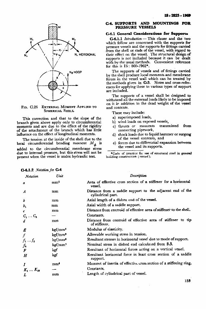
Fro. (3.26 EXTERNAL MOMENT APPHED TO
SPHERICAL SHELL
This correction and that to the slope of the branch given above apply only to circumferential moments and are due to the effect of the rigidity of the attachment of the branch which has little influence on the effect of longitudinal moments.
The tension at the inside of the shell due to the local circumferential bending moment M+ is
added to the circumferential membrane stress due to internal pressure, but this stress will not be present when the vessel is under hydraulic test.
c.4.1.2 Notation for c-4
JVotation Unit
a
A mm
b mm
bi mm
c mm
G . . . G - d mm
kgf/mm’
kgf/mms
kgf/mms
kgf/mm2
W
kf
mm4
- mm
IS:2825-1968
C-4. SUPPORTS AND MOUNTINGS FOR PRESSURE VESSELS
C-4.1 General Considerations for Snpporr~
C4.1.1 Introduction - This clause and thei two which follow are concerned with the supports for pressure vessels and the supports for fittings carried .from the shell or, ends of the vessel, with regard to their effect on the vessel. The structural design of supports is not included because it can be dealt with by the usual methods. Convenient reference for this is IS : 800-1!362*.
The supports of vessels and of fittings carried by the shell produce local moments and membrane forces in the vessel wall which can be treated by the methods given in G5. Notes and cross-refer- ences for applying these to various types of support are included.
The supports of a vessel shall be designed to withstand all the external ioads likely to be imposed on it in addition to the dead weight of the vessel and contents.
These may include:
4 b) 4
4
4
superimposed loads, wind loads on exposed vessels, thrusts or moments transmitted from connecting pipework, shock loads due to liquid hammer or surgmg of the vessel contents, and forces due to differential expansion between the vessel and its supports.
*Code of practice for use of structural steel in general building construction ( revised).
Descri$tion
Area of effective cross section of -a stiffener for a horizontal vessel.
Distance ffom a saddle support to the adjacent end of the cylindrical part.
Axial length of a dishea end of the vessel.
Axial width of a saddle support.
Distance from centroid of effective area of stiffener to the shell.
Constants.
Distance from centroid of eflective area of stiffener to tip of stiffener.
Modulus of elasticity.
Allowable working stress in tension.
Resultant stresses in horizontal vessel due to mode of support.
Nominal stress in dished end calculated from 5.5.
Resultant of horizontal forces acting on a vertical vessel.
Resultant horizontal force in least cross section of a saddle support.
Moment of inertia of effective cross section of a stiffening ring.
Constants.
Length of cylindrical part of vessel.
155
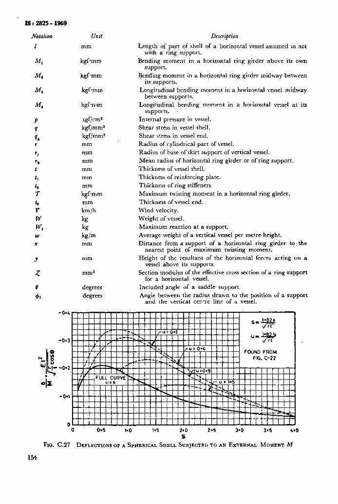
IS I 2825 - 1969
Notation
1
Ml
M8
M4
P
4
% r
f I
‘1 t
t1
t ,
7
tb
V
W
WI W
Jr
Y
5
Fso. C.27
154
Untt
mm
kgfmm
kgf-mm
kgf mm
kgfrnm
igf/cm*
kgf/mm*
kgf/mms
mm
mm
mm
mm
mm
mm
kgf *mm
mm
km/h
kg
kg
kg/m mm
mm
mm9
degrees
degrees
Description:
Length of part of shell of a horizontal vessel assumed to act with a ring. support.
Bending moment in a horizontal ring girder above its own support.
Rending moment in a. horizontal ring girder midway betw-etn its supports.
Longitudinal bending moment in a horizontal vessel midway between supports.
Longitudinal bending moment in a horizoutal vessel at its supports. ~
Internal pressure in vessel.
Shear stress in vessel shell.
Shear stress in vessel end.
Radius of cylindrical part of vessel.
Radius of base of skirt support of vertical vessel.
Mean radius of horizontal ring girder or of ring support.
Thickness of vessel shell.
Thickness of reinforcing plate.
Thickness of ring stiffeners.
Maximum twisting moment in a horizontal ring girder.
Thickness of vessel end.
Wind velocity.
Weight of vessel.
Maximum reaction at a support.
Average weight of a vertical vessel per metre height.
Distance from a support of a horizontal ring girder to the nearest point of maximum twisting moment.
Height of the resultant of the horizontal forces acting on a vessel above its supports.
Section modulus of the effective cross section of a ring support for a horizontal vessel.
Included angle of a saddle support.
Angie between the radius drawn to the position of a support and the vertical cerf’.re line of a vessel.
0 0*5 1.0 l-5 2.0 2-5 3*0 3-5 44 s
DEFLECTIONSOF ASPHERICAL SHELL SUBJECTEDTO AN EXTERNAL MOMENT M
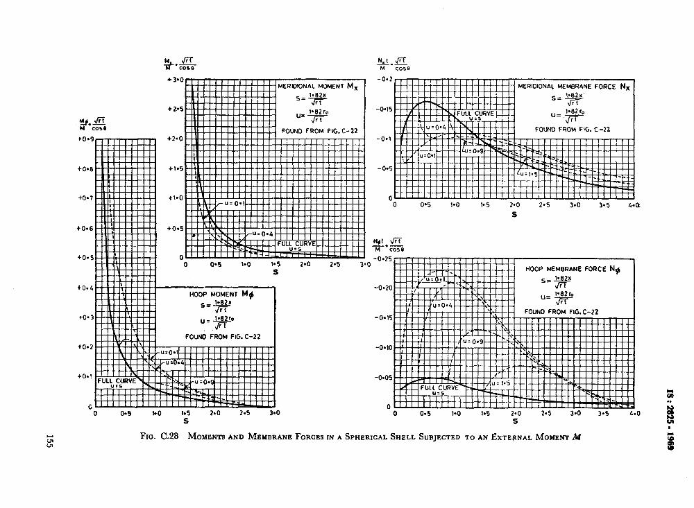
to.6
h&&-i l COSB
+3-o
+ 2.4
+2*0
4.105
tr.0
+0*5
0
-0.20
-0.15
-0.10
-0*05
0 0 0*5 1-O 1.5 2*0 2-5 3.0 3.5
S
FIG. C.28 MOMENTSAND MEYBRA ,NE FORCES IN A SPHERICAL SHELL SUBJECTED TOAN EXTERNAL MOMENTM
N,I ./X xi--- CO58
-0.2
-045
-O*l
-0.5
0 0 0'5 1.0 l* 5 2-O 2*5 3.0 3.5 44
S
-0.25
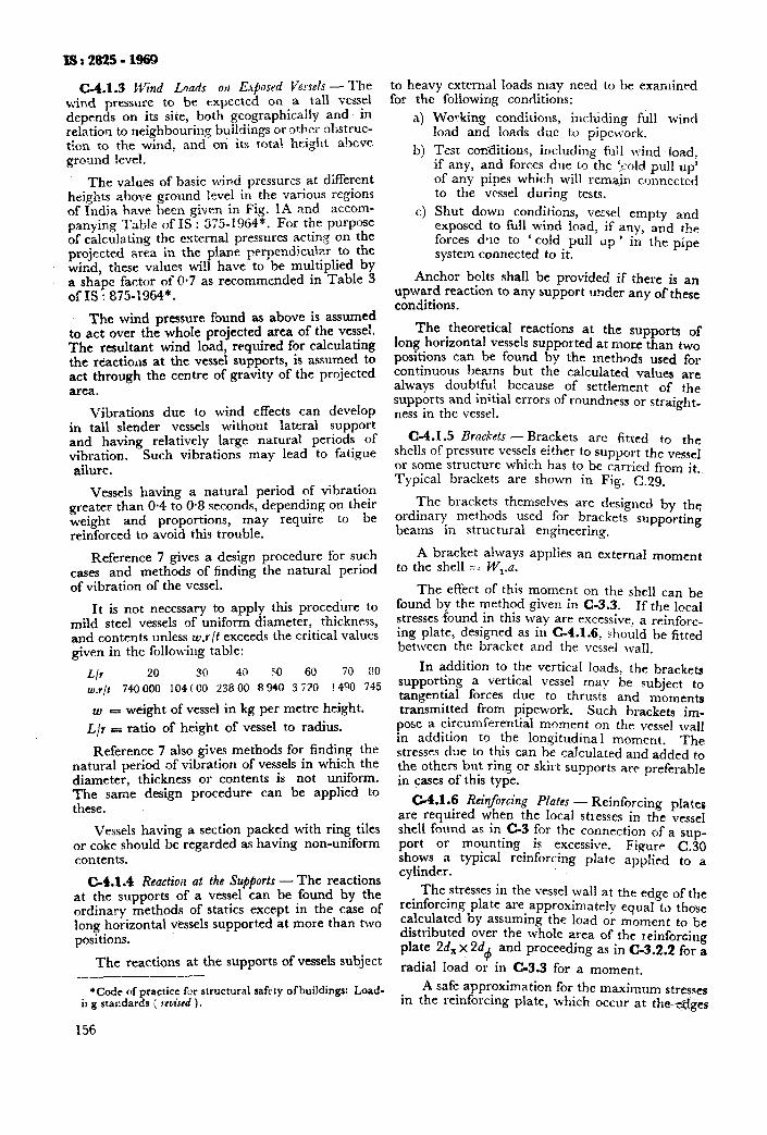
1s:282!5-1969
C-4.1.3 CVind Loads 011 Eqhsrd Vmels - The windy pressure to be expected on a rall vessel depends on its site, both geographically and. in relation to neighbouring buildings or Other obstruc- tion to the wind, and on’ its rota1 height abcve ground level.
The values of basic wind pressures at different heights above ground level in the various regions of India have been given in Fig. 1A and accom- panving Table of IS : 8X-1964*. For the purpose of c&ulating the external pressures acting on the projected area in the plane perpendicular to the wind, these values wi!l have to be multiplied by a shape factor of 0.7 as recommended in Table 3 of IS : 875-1%%4*.
The wind pressure found as above is assumed to act over the whole projected area of the vessel. The resultant wind load, required for calculating the reactions at the vessel supports, is assumed to act through the centre of gravity of the projected area.
Vibrations due to wind effects can develop in tall slender vessels without lateral support and having relatively large natural periods of vibration. Such vibrations may lead to fatigue ailure.
Vessels having a natural period of vibration greater than O-4 to 0.8 seconds, depending on their weight and proportions, may require to be reinforced to avoid this trouble.
Reference 7 gives a design procedure for such cases and methods of finding the natural period of vibration of the vessel.
It is not necessary to apply this procedure to mild steel vessels of uniform diameter, thickness, and contents unless w.r/t exceeds the critical values given in the following table:
L/r 20 30 40 50 60 70 80
w/t 740000 104CGO 23800 890 3i70 !490 745
VJ- weight of vessel in kg per metre height.
L/r = ratio of height of vessel to radius.
Reference 7 also gives methods for finding the natural period of vibration of vessels in which the diameter, thickness or contents is not uniform. The same design procedure can be applied to these.
Vessels having a section packed with ring tiles or coke should be regarded as having non-uniform contents.
C-4.1.4 Reactioiz at the Supports -The reactions at the supports of a vessel can be found by the ordinary methods of statics except in the case of long horizontal vessels supported at more than two positions.
The reactions at the supports of vessels subject -_
*Code of practice fix structural safety ofbuildings: Load- il g standards ( woiscd ).
156
to heavy external loads may need to be examined for the following conditions:
4
b)
4
Working conditions, in&ding full wind load and loads due to pipework.
Test cor%Etions, including fil;l wind load: if any, and forces due to the tcold pull up’ of any pipes which will rem+ connected to the vessel during tests.
Shut down conditions, vetsel empty and exposed to full wind load, if any, and the forces d-le to ‘ cold p11 tip ’ in the pipe system connected to it.
Anchor bolts shall be provided if there is an upward reacticn to any support under any of these conditions.
The theoretical reactions at the supports of long horizontal vessels supported at more than two positions can be found by the methods used for continuous beams but the calculated values are always doubtfu! because of settlement of the supports and initial errors of roundness or straight- ness in the vessel.
C-4.1.5 Brackets-Brackets are fitted to the
shells of pressure vessels either to support the vessel or some structure which has to be carried f+om it. Typical brackets are shown in Fig. C.29.
The brackets themselves are designed by the ordinary methods used for brackets supporting beams in structural engineering.
A bracket always applies an external moment to the shell = W,.a.
The effect of this moment on the shell can be found by the method given in C-3.3. If the local stresses ,found in this way are excessive, a reinfore- ing plate, designed as in C-4.1.6, should be fitted between the bracket and the vessel wall.
In addition to the vertical loads, the brackets supporting a vertical vessel may be subject to tangential forces due to thrusts and moments transmitted from pipework. Such brackets im-
pose a circumferential moment on the vessel wall in addition to the longitudinal moment. The stresses clne to this can be calculated and added to the others but ring or skirt supports are preferable in cases of this type.
C-4.1.6 Reinforcing Plates - Reinforcing plates are required when the local stresses in the vessel shell found as in.C-3 for the connection of a sup- port or mountmg is excessive. Figure C.30 shows a typical reinforcing plate applied to a cylinder.
The stresses in the vessel wall at the edge of the reinforcing plate are approximately equal to those calculated by assuming the load or moment to be distributed over the whole area of the reinforcing plate 26, x 2d4 and proceeding as in C-3.2.2 for a
radial load or in C-3.3 for a moment.
A safe approximation for the maximum stresses in the reinforcing plate, which occur at theeges
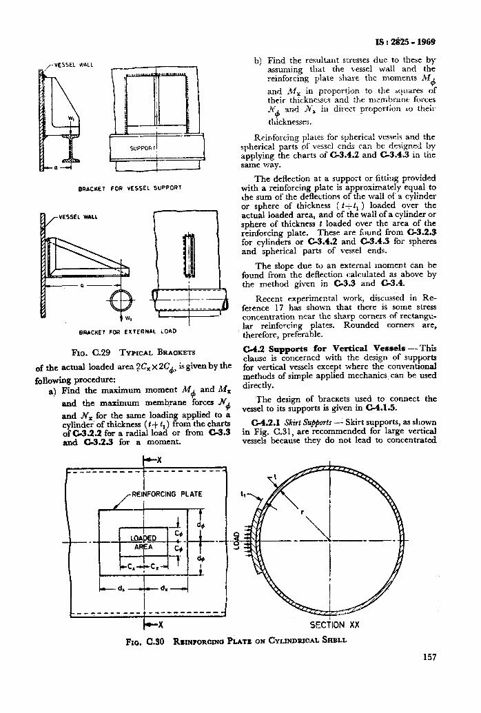
BRACItE FOR VESSEL SUPPORT
Iv VESSEL WALl
u i WI --t-
BRACKET FOR EXTERNAL LOAD
Fro. C.29 TYPICAL BRACKETS
of the actual loaded area ?Cx x 2C+ is given by the
following procedure: a) Find the maximum moment A4
4 and Al,
and the maximum membrane forces .N+
and N, for the same loading applied to a cylinder’ of thickness ( t+ 1r) from the charts of C-3.2.2 for a radial load or from C-3.3 and C-3.2.3 for a moment.
IS : 2ti225 - 1969
Find the resultant stresses due to these by assuming that the vessel wali and the reinforcing plate share the moments M
d and M, in proportion to the bquares of their thicknesses and the membrane forces N+ and Jvr in direct propcrtion LO thei:.
thicknesses.
Reinforcing piates for spherica! vesseis and the spherical parts of vessel ends can be designed by applying the charts of C-3.4.2 and C-3.4.3 in tne same vra,y.
The deflection at a support or fitting provided with a reinforcing plate is approximately equal to the sum of the deflections of the wail of a cylinder or sphere of thickness ( t+t, ) loaded over the actual loaded area, and of the wall of a cylinder or sphere of thickness t loaded over the area of the reinforcing plate. These are found from C-3.2.3 for cylinders or C-3.4.2 and C-3.4.3 for spheres and spherical parts of vessel ends.
The s!ope due to an external moment can be found from the deflection calculated as above by the method given in C-3.3 and C-3.4.
Recent experimental work, discussed in Re- ference 17 has shown that there is some stress concentration near the sharp corners of rectangc- lar reinfcrcing plates. Rounded comers are, therefore, preferable.
C-4.2 Supports for Vertical Vessels -- This clause is concerned with the design of supports for vertical vessels except where the conventional methods of simple applied mechanics can be used directly.
‘The design of brackets used to connect the vessel to its supports is given in C-4.1.5.
C-4.2.1 Skirt Supports - Skirt supports, as shown in Fig. C.31, are recommended for large vertical vessels because they do not lead to concentrated
)cX SECilON XX
Fxo. C.30 REMFORarrW PLATE ON CYLIN~RKIAL SHELL
157
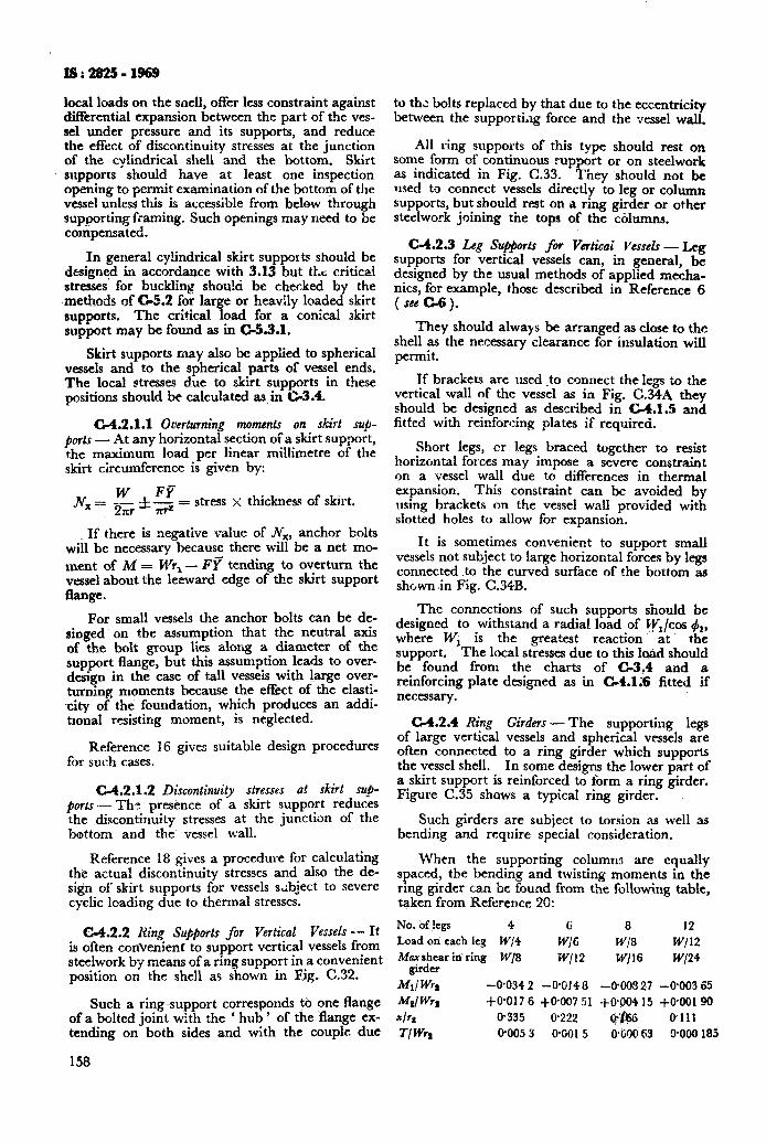
ls:2925-1969
local loads on the snell, offer less constraint against differential expansion between the part of the ves- sel under pressure and its supports, and reduce the effect of discontinuity stresses at the junction of the cylindrical shell and the bottom. Skirt supports should have at least one inspection opening to permit examination of the bottom of the vessel unless this is accessible from below through sup.porting f:aming. Such openings may need to be compensated.
In general cylindrical skirt supports should be designed in accordance with 3.13 but t1.c: critical stresses for buckling shou!ci be checked by the met&& of G5.2 for large or heavily loaded skirt supports. The critical. load for a conical skirt support may be found as in C-53.1.
Skirt supports may also be applied to spherical vessels and to the spherical parts of vessel ends. The local stresses d.ue to skirt supports in these positions should be calculated as in C-3.4.
C-4.2.1.1 Overturning moments on skirt suj- p0rt.f - At any horizontal section of a skirt support, the maximum load per linear millimetre of the skirt circumference is given by:
Nx” ~p&k$ stress >( thickness of skirt.
If there is negative ~aluc of N,, anchor bolts will be necessary because there will be a net mo-
ment of M = M’r, - F? tending to overturn the vessel about the leeward edge of the skirt support flange.
For small vessels the anchor bolts can be de- singed on the assumption that the neutral axis of the bolt group lies along a diameter of the support flang?, but this assumption leads to over- design in the case of tall vesseis with large over- turning moments because the effect of the elasti- .city of the foundation, which produces an addi- tlonal resisting moment, is neglected.
Reference 16 gives suitable design procedures for such cases.
C-4.2.1.2 Discontinuity stresses at skirt SUP_
ports- TRIP presence of a skirt support reduces the ,discontinuity stresses at the junction of the bottom and the vessel wall.
Reference 18 gives a procedme for calculating the actual discontinuity stresses and also the de- sign of skirt supports for vessels subject to severe cyclic loading due to thermal stresses.
C-4.2.2 Ring Su@orts for Vertical Vesseh -- It is often conVenienf to support vertical vessels from steelwork by means of a ring support in a convenient position on the shell as shown in Fig. C.32.
Such a ring support corresponds to one flange of a bolted joint with the ‘ hub ’ of the flange ex- tending on both sides and with the couple due
158
to th,: bolts replaced by that due to the eccentricity between the supporti,lg force and the vessel wall.
All ring supports of this type should rest on some form of continuous rupport or on steelwork as indicated in Fig. C.33. They ‘should not be used to connect vessels directly to leg or column supports, but should rest on a ring girder or other steelwork joining the tops of the cdnmns.
C-4.2.3 Leg Stlpports fw Verticai l~essels - Leg supports for vertical vessels can, in general, be designed by the usual methods of applied mecha- nics, for example, those described in Reference 6 ( see c.6).
They should always be arranged as close to the shell as the necessary clearance for insulation will permit.
If brackeu are used .to connect the legs to the vertical wall of the vessel as in Fig. C.34A they should be designed as described in C-4.1.5 and fitted with reinforcing plates if required.
Short legs, cr legs braced together to resist horizontal forces may impose a severe constraint on a vessel wall due to differences in thermal expansion. This constraint can be avoided by using brackets on the vessel wall provided with slotted holes to allow for expansion.
It is sometimes convenient to support small vessels not subject to large horizontal forces by legs connected .to the curved surface of the bottom as shc,wn in Fig. C.34B.
The connections of such supports should be designed to withstand a radial load of Ct;/cos +,, where WI is the greatest reaction at the support. The local stresses due to this 1-d should be found from the charts of G3.4 and a reinforcing plate designed as in C-4.1.6 fitted if necessary.
C-4.2.4 Ring Girders-The supporting legs of large vertical vessels and spherical vessels are often connected to a ring girder which supports the vessel shell. In some designs the lower part of a skirt support is reinforced to form a ring girder. Figure C.35 shows a typical ring girder.
Such girders are subject to torsion as well as bending and require special consideration.
When the supporting columr~s are equally spaced, the bending and twisting moments in the ring girder can be found from the following table, taken from Reference 20:
No. of !egs 4 6 8 12 Load on each leg W,‘4 W/C WI8 w/12 M;;trar in ring W/8 w/12 W/16 W/24
W’WQ -0.034 2 -0.014 8 -0908 27 -@003 65
hi WQ l-O.0176 $OfN751 -t_O$M415 +090190
*IF? 0.335 0.222 afw Pill
Tl Wr, 0.005 3 0.0015 O+OO 63 9000 185
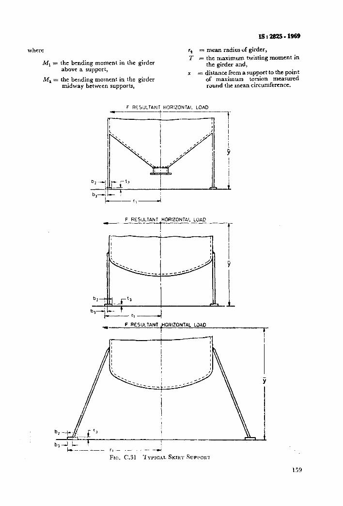
where
Ml =
‘21, =
r, = mean radius of girder,
I- = the maximum twisting moment in the girder and,
x = distance from a support to the point of maximum torsion measured round the mean circumference.
the bending moment in the girder above a support,
the bending moment in the girder midway between supports,
F RESULTANT HOR!ZONTA!_ LOAD
- F RESULT4NT IHORIZONTA’_ iOAC
i --l-
w F RESULTANT HORIZONTAL L3AD
-t-
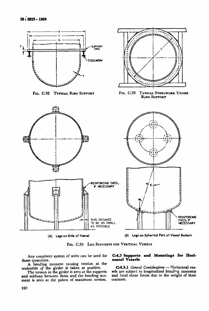
FIO. C.32 TYPICAL RINO SUPPORT
(A) Legs on Side of Vessel
/- REINFORCING PADS,
F NECESSARY
THIS DISTANCE
Fro. C.33 TYPICALSTEELWORK UNDER &No SUPPORT
NECESSARV
(B) Legs on Spherical Part of Vessel Bottom
Fro. C.34 LEO SUPPORTS FOR VEKTICALVESSELS
Any consistent system of units can be used for C-4.3 Supports and Mountings for Horim these quantities. zontzl Vessels
A bending moment causing tension at the underside of the girder is taken as positive. C-4.3.1 General Consideration - Tiorizontal ves-
The torsion in the girder is zero at the supports sels are subject to longitudinal bending moments and midway between them and the bending mo- and local shear forces due to the weight of their ment is zero at ,the points of maximum torsion. contents.
160
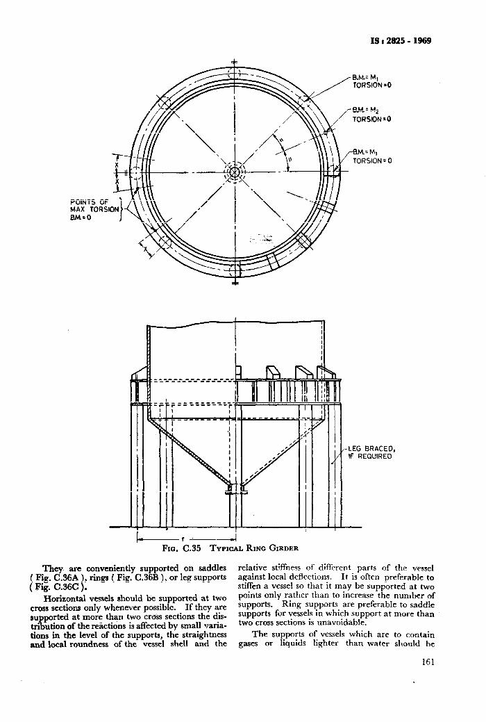
POINTS MAX 10 BM=O
IS : 2925 - 1969
I------- ----4 Fxa. C.35 TYPICAL RING GIRDER
‘I’hev are convenientlv supported on saddles ( Fig. C!.36A ), rings ( Fig: C.36R ), or leg supports ( Fig. C.36C ).
Horizontal vessels should be supported at two cross sections only whenever possible. If they are supported at more than two cross sections the dis- tribution of the reactions is affected by small varia- tions in the level of the supports, the straightness and local roundness of the vessel shell and the
IF REQUIRED
relative stiffness of different parts of the vessel against local deflections. It is often preferable to stiffen a vessel so that it may be supported at two points only rather than to increase the number of supports. Ring supports are preferable to saddle supports for vessels in which support at more than two cross sections is unavoidable.
The supports of vessels which are to contain gases or liquids lighter than water should be
161
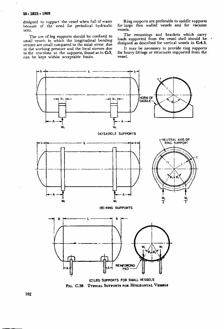
IS : 2825 - 1969
designed to support the vessel when full of water Ring supports are preferable to saddle supports because of the need for periodical hydraulic for large thin walled vessels and for vacuum tests. vessels.
The use of leg supports should be confined to The mountings and brackets which carry
small vessels in which the longitudinal bending loads supported from the vessel shell should be 1
stresses are small compared to the axial stress due designed as described for vertical vessels in G&l.
to the working pressure and the local stresses due It may be necessary to provide ring supports to the reactions at the supports, found as in C-3, for heavy fittings or structures supported from the can be kept within acce$ble limits. vessel.
(A) SADDLE SUPPORTS
-A- I 1
Wl
-A-
b -7-l
-4
NEUTRAL AXIS OF RING SUPPORT
(9) RING SUPPORTS
(C)LEG SUPPORTS FOR SMALL VESSELS
FIO. C.36 TYPICAL SUPPORTS FOR HORIZONTAL vES#RLB
162
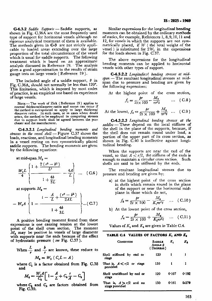
IS : 2925 - 1969
Similar expressions for the longitudinal bending moments can be obtained by the ordinary methods of statics, for example, References 1, 8,9,10,11 and 12, for vessels in which the supports are not sym- metrically placed, if W ( the total weight of the vessel ) is substituted for 2 WI in the expressions for the loads shown in Fig. C.37.
The above expressions for the longitudinal bending moments can be applied to horizontal vessels with other types of support.
C-4.3.2.2 Longitudinal bending stresses at mid- span - The resultant longitudinal stresses at mid- span due to pressure and bending are given by the following expressions:
At the highest point of the cross section,
C-4.3.2 Saddle Supports - Saddle supports, as shown in Fig. C.36A are the most frequently used type of support for horizontal vessels although no rigorous analytical treatment of them is available. The methods given in C-3 are not strictly appli- cable to loaded areas extending over the large proportion of the total circumterence of the vessel which is usual for saddle supports. The following treatment which is based on an approximate analysis discussed in Reference 19. The analysis gives a good approximation to the results of strain gauge tests on large vessels ( R.eference 19 ).
The included angle of a saddle support, i3 in Fig. C.36A, should not normally be less than 120”. This limitation, which is imposed by most codes of practice, is an empirical one based on experience of large vessels.
Nora -The work of Zick (Reference 19) applies to normal thickness/diameter ratios and errors can occur if the method is extrapolated to apply to large thickness/ diameter ratios. In such casq or in cases where doubt arises, the method to be employed in computing stresses due to support loads shall be agreed between the pur- chaser and the manufacturer.
G4.3.2.1 Longitudinal bending moments and stresses in the vessel shell - Figure C.37 shows the loads, reactions, and longitudinal bending moments in a vessel resting on two symmetrically placed saddle supports. The bending moments are given by the following equations:
at mid-span MS =
at supports M, =
i
1 ;+(12-b2) -- 2AL
- W,A 1 -
i
. ..( C.7) 4b
1 + 3z
A positive bending moment found from these expressions is one causing tension at the lowest point of the shell cross section. The moment L%$ may be positive in vessels of large diameter with supports near the ends because of the effect of hydrostatic pressure ( see Fig. C.37 ).
When + and 4 are known, these reduce to
M * = W, ( C,L - A)
where C, is a factor obtained from Fig. and
where C and Cs are factors obtained Fig. C.39.
. . . (C.8)
M Atthelowest,f,=2t~loo+--& . . . (C.9)
C-4.3.2.3 Longitudinal bending stresses at the saddles-These depend on the local stiffness of the shell in the plane of the supports, because, if the shell does not remain round under load, a portion of the upper part of its cross section, as shown in Fig. C.40 is ineffective against longi- tudinal bending.
When the supports are near the end of the vessel, so that A < r/2, the stiffness of the ends is enough to maintain a circular cross section. Such shells are said to be stiffened by the ends.
The resultant longitudinal stresses due to pressure and bending are given by:
a) at the highest point of the cross section in shells which remain round in the plane of the support or near the horizontal mid- plane in those which do not,
M +A!.__--L 2t x 100 IC,xr”t
. . . (C.10)
b) At the lowest point of the cross section,
f4 = pr 2t x 100 +
M ---!!.- . . . (C.11) K21rr2t
Values of Kr and X2 are given in Table C.4.
TABLE C.4 VALUES OF FACTORS Kl AND K,
CONDITION SADDLE K-1 X8 ANOLB fj
(DEOREES)
Shell stitfcned by end or 120 1 1 rings
C.38 T’r;liedA < r/2 or rings
Shell unstiffened by end or riXlgs
from That is, A > r/2 and no rings provided
150 1 1
120 0.107 9192
150 9161 a279
163
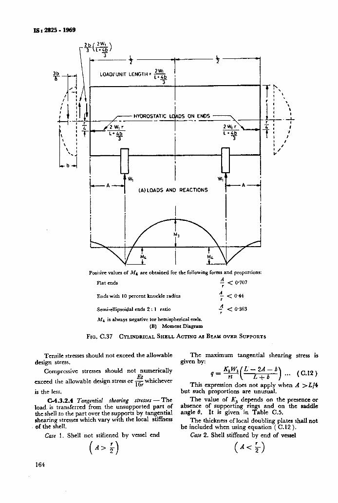
LOAD/ UNIT LENGTH = sb !
T
- P
I I
I W A
(A) LOADS AND REACTIONS 7-i
Positive values of Md are obtained for the following forms and proportions:
Flat ends ” < 0.707
Ends with 10 percent knuckle radius 4 < 0.44
Semi-ellipsoidal ends 2 : 1 ratio 4 < 0.363
Md is always negative tor hemispherical ends.
(B) Moment Diagram
FIG. C.37 CYLINDRICAL SHELL ACTING AS BEAM OVER SUPPORTS
Tensile stresses should not exceed the allowable The maximum tangential shearing stress is design stress. given by:
Compressive stresses should not Eymerically
exceed the allowable design stress or-whichever 16r is the less.
I
C-4.3.2.4 Tangential shearing stresses - The load is transferred from the unsupported part of the shell to the part over the supports by tangential shearing stresses which vary with the local stiffness of the shell.
Case 1. Shell not stifiened by vessel end
This expression does not apply when A >L/4 but such proportions are unusual.
The value of 5s depends on the presence or absence of supportmg rings and on the saddle angle 8. It is given in Table C.5.
The thickness of local doubling plates shall not be included when using equation ( C.12 ).
Care 2. Shell stiffened by end of vessel
(A>;) 164
(A< 5)
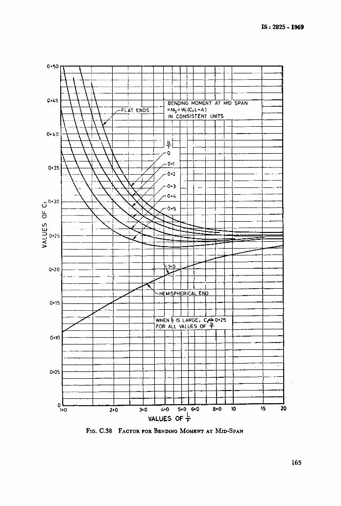
IS:2825-1969
=M.=W.(C,L-A)
0.35
.-0*30 v
k
ln W, 3 0.25
2
0.20
I
WHEN f FOR AL
I
nl I I I I 1 I I III
-1.0 2*0 90 4-O $0, 64 8*0 10 15 20
VALUES OF f
FIG. C.38 FACTOR FOR BENDINCJ MOMENT AT MID-SPAN
165
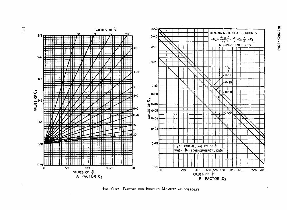
0 0.25 0*5
VALUES OF h
A FACT&?
o-75 1-o
c2
040
= 1 (HEMISPHERICAL END)
2*0 3.0 4.0 5-O 6.0
VALUES OF #
8-O 10-O
B FACTOR C3
-FIG. C.39 FACTORS FOR BENDING MOMENT AT SUPPORTS
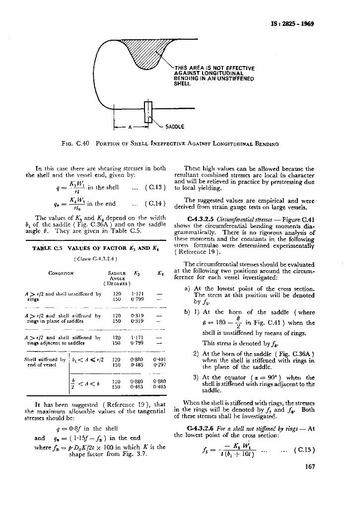
IS : 2925 - 1969
THIS AREA IS NOT EFFECTIVE AGAINST LONGITUDINAL BENDING IN AN UNSTIFFENED SHELL
Fxa. C.40 PORTION OF SHELL INEPFECTIVE AGAINST LONGITUDINAL BENDING
In this case there are shearing stresses in both the shell and the vessel end, given by:
KW 3 in the shell
q= rt . . . (C.13)
K4 w1 in the end qe = - . . . rte
( c.14 )
The values of K, and K, depend on the width b, of the saddle ( Fig. C36A ) and on the saddle angle 0.. They are given in Table C.5.
TAEiLE C.5 VALUES OF FACTOR Ks AND K4
( C’laue c-4.3.2.4 )
CONDITION SADDLE K3 K4 ANGLE
( DEGREES )
A ) r/2 and shrll unstiffened by 120 1.171 - rings 150 0,799 -
A > r/2 and shell stiffened by 120 0.319 - rings in plane of saddles 150 0.319 -
A > r/2 and shell stiffened by 120 1.171 - ringa adjacent to saddles 150 0.799 -
-
Shell stiffened by b, < A < r/2 120 0.880 0.401 end of vessel 150 0.485 0,297
+<A<b 150 120 0.880 0.485 0380 0.485
It has been suggested ( Reference 19 ), that the maximum allowable values of the tangential stresses should be:
q = 0.8f in the shell
and qe - ( 1*15f--f,) in the end
where fn = pD,K/Pt x 100 in which X is the shape factor from Fig. 3.7.
These high values can be allowed because the resultant combined stresses are local in character and will be relieved in practice by prestressing due to local yielding.
The suggested values are empirical and were derived from strain gauge tests on large vessels.
C-4.3.2.5 Circumferential stresses - Figure C.41 shows the circumferential bending moments dia- grammatically. There is no rigorous analysis of these moments and the constants in the following stress formulae were determined experimentally ( Reference 19 ).
The circumferential stresses should be evaluated at the following two positions around the circum- ference for each vessel investigated:
a) At the lowest point of the cross section. The stress at this position will be denoted
z- by
b) 1) JS.
At the horn of the saddle ( where
fi = 180 - $ in Fig. C.41 ) when the
shell is unstiffened by means of rings.
This stress is denoted by fa.
At the horn of the saddle ( Fig. C.36A ) when the shell is stiffened with rings in the plane of the saddle.
At the equator ( a = 90” ) when the shell is stiffened with rings adjacent to the saddle.
2)
3)
When the shell is stiffened with rings, the stresses in the rings will be denoted by f, and f,. Both of these stresses shall be investigated.
C-4.3.2.6 For a shell not dyened by rings - At the lowest point of the cross section:
fs = - Kti w, t (b, + lot) ***
. . . (C.15)
167
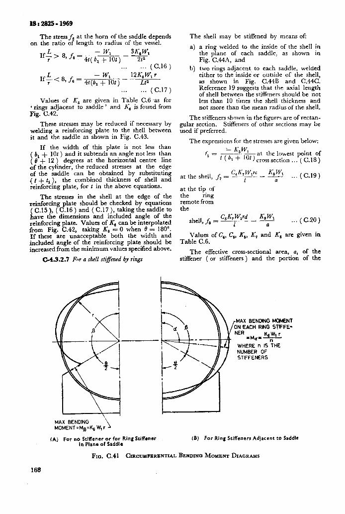
The stress fa at the horn of the saddle depends on the ratio of length to radius of the vessel.
If; - > 8, fe w1 - 3% WI 4t( 6, + lot) 2t2
. . . 1.. (C.16)
L - WI 1f;c8,f,= 4t(b,+ lot)-
12Ec, W, r LP
. . . . . . (C.17)
Values of Ks are given in Table C.6 as for 6 rings adjacent to saddle ’ and K6 js found from Fig. C.42.
These stresses may be reduced if necessary by welding a reinforcing plate to the shell between it and the saddle as shown in Fig. C.43.
If the width of this plate is not less than ( b, + lot ) and it subtends an angle not less than ( 8 + 12 ) degrees at the horizontal centre line of the cylinder, the reduced stresses at the edge of the saddle can be obtained by substituting ( t + t1 ), the combined thickness of shell and reinforcing plate, for t in the above equations.
The stresses in the shell at the edge of the reinforcing plate should be checked by equations (C.15), (C.16) and ( C. 17 ), taking the saddle to have the dimensions and included angle of the reinforcing plate. Values of K,, can be interpolated from Fig. C.42, taking K’s = 0 when 0 = 180”. If these are unacceptable both the width and included angle of the reinforcing plate should be increased from the minimum values specified above.
C-4.3.2.7 For a shell stiffened by rings
The shell may be stiffened by means ofi
a) a ring welded to the inside of the shell in the plane of each saddle, as shown in Fig. C.44A, and
b) two rings adjacent, to each saddle, welded either to the inside or outside of the shell, as shown in Fig. C.44B and C.44C. Reference 19 suggests that the axial length of shell between the stiffeners should be not less than 10 times the shell thickness and not more than the mean radius of the shell.
The stiffeners shown in the figures are of rectan- gular section. Stiffeners of other sections may be used if preferred.
The expressions for the stresses are given below:
f5 = L K5W,
-at the lowest point of t (bl-t 10t)crosssection... (C.18)
C, K, W,rc K, Wl at the shell, f, = P-F - -
a . . . (C.19)
at the tip of the ring remote from the
shell, fe = C, K, W,rd X8 WI
- ___ 1 a ..* (C.20)
Values of C,, Cs, K,, K7 and K8 are given in Table C.6.
The effective cross-sectional area, a, of the stiffener ( or stiffeners ) and the portion of the
+4X BENDING VENT EACH RING STIFFE-
NER ZM#Z KgWl r
WHERE n IS ?HE NUMBER OF STIFFENERS
I \ I I MAX BENDING
1 MOMENT =Ma=Ks W, r
(A) For no Stiffener or for Ring Stiffener (B) For Ring Stiffeners Adjacent to Saddle in Plane of Saddle
FIG. C.41 CIRCUMFERENTIAL BENDINO MOMENT DIAGRAMS
168
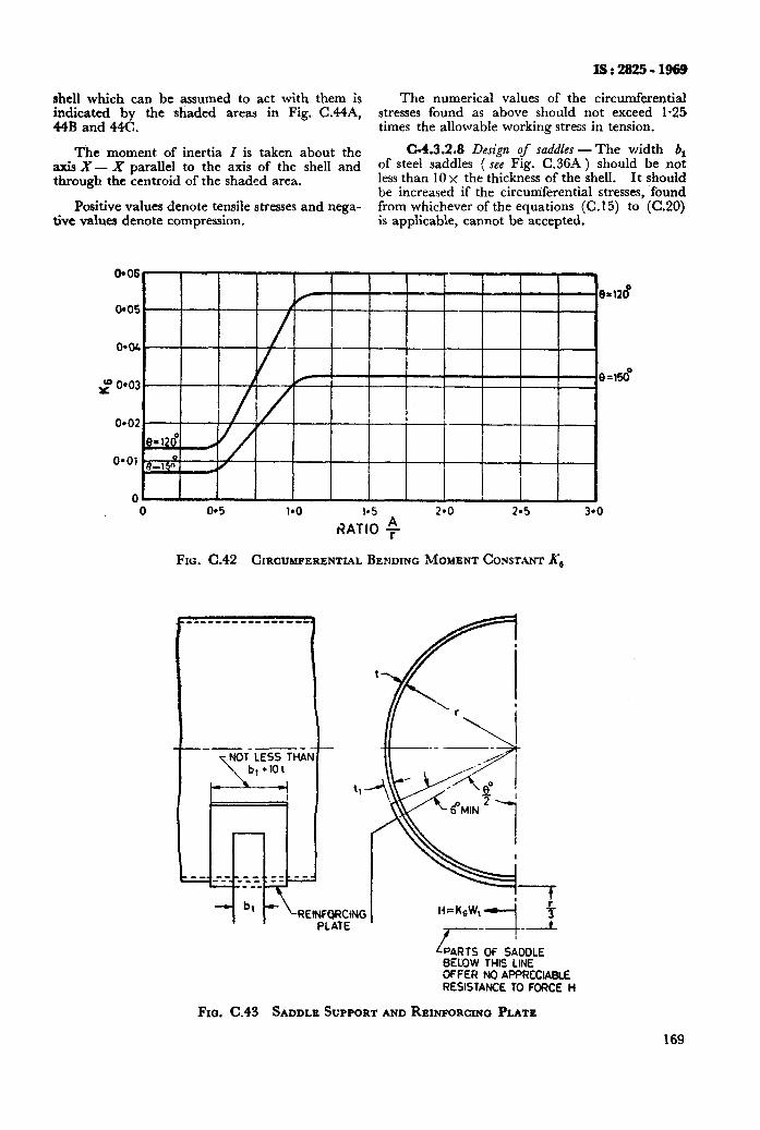
lS:2825-1969
The numerical values of the circumferential stresses found as above should not exceed 1.25 times the allowable working stress in tension.
C-4.3.2.8 Design of saddles- The width 6, of steel saddles ( see Fig. C.36A ) should be not less than 10 x the thickness of the shell. It should be increased if the circumferential stresses, found from whichever of the equations (C.15) to (C.20) is applicable, cannot be accepted.
shell which can be assumed to act with them is indicated by the shaded areas in Fig. C.44A, 44B and 44C.
The moment of inertia I is taken about the axis X- X parallel to the axis of the shell and through the centroid of the shaded area.
Positive values denote tensile stresses and nega- tive values denote compression.
0*06
0 0 0.5 l*O I.5 2-o 2.5 3-O
t?ATIO $
FIG. C.42 CIRCUMFERENTIAL BENDING MOMENT CONSTANT Ks
LPARTS OF SADOLE BELOW THIS LINE OFFER NO AF’PRCCIABCE RESISTANCE TO FORCE H
FIG. C.43 SADDLE SUPPORT AND REINFORCING PLATE
169
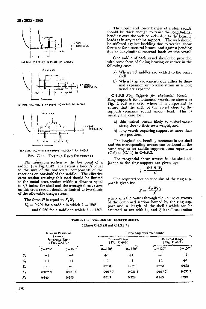
26 i 2825 - 1969
__f I =wEcL
TcwcK)(Ess
7
(A) RING STIFFENER IN PLANE OF SADDLE
‘(8) INTERNAL RING STlFFENERS ADJACENT TO SADDLE
03 EXTERNAL RING STIFFENERS ADJACENT 10 SADDLE
FIG. G.44 TYPICAL RING STIFFENERS
The minimum section at the low point of a saddle (see Fig. C-43 ) shall resist a force H equal to the sum of the horizontal components of the reactions on one-half of the saddle. The effective cross section resisting this load should be limited to the metal cross section within a distance equal to r/3 below the shell and the average direct stress on this cross section should be limited to two-thirds of the allowable design stress.
The force H is equal to K,, WI
X, = 0.204 for a saddle in which ~9 = 120”,
and O-260 for a saddle in which 0 = 1509
The upper and lower flanges of a steel saddle should be thick enough to resist the longitudinal bending over the web or webs due to the bearing loads as in any machine support. The web should be stiffened against buckling due to vertical shear forces as for structural beams, and against bending due to longitudinal external loads on the vessel.
One saddle of each vessel should be provided with some form of sliding bearing or rocker in the following cases:
a) When steel saddles are welded to the vessel shell.
b) When large movements due either to ther- mal expansion or to axial. strain in a long vessel are expected.
C-4.3.3 Ring Su@orts for Horizontal Vessels - Ring supports for horizontal vessels, as shown in Fig. C.36B are used where it is important to ensure that the shell of the vessel close to the supports . remains round under load. This is usually the case for:
a) thin walled vessels iike!y to distort exces- sively due to their own weight, and
b) long vessels requiring support at more than two positiorrs.
The longitudinal bending moments in the shell and the corresponding stresses can be found in the same way as for saddle supports from equations (C.6) to (C.ll) in c-4.3.2.
The tangential shear stresses in the shell ad- jacent to the ring support are given by:
4 S o-319 w, rt
The required section modulus of the ring sup- port is given by:
where r, is the’radms through the centre of gravny of the combined section formed by the ring sup- port and a length of the shell 1 yhich can be assumed to act with it, and 5 is the least section
TABLE C.6 VALUES OF COEFFICIENTS
( Clauses C-4.3.2.6 and C-4.3.2.7 )
RIM IN PLANE OF SADDLE
INTERNALRINQ ( Fro. C.44A )
r---____~ e=1200 @= 1.500
-1 -1
+1 $1
-- -
-0.052 8 0.031 6
0.340 0.303
RIN~SADJACENTTOSADDLE I__---- A--__--,
Internal Rings External Ringr (Fig. C.44B) ( Fig. C.44C )
y-d___ c---- 8-120~ 8=150” I.+ 1200 e-150*
+1 +1 -1 -1
-1 -1 -l-l +1
0.760 0.613 a.760 0.673
0.057 7 0.035 3 O-057 7 WO35 3
0.263 0.228 0.263 O-228
170
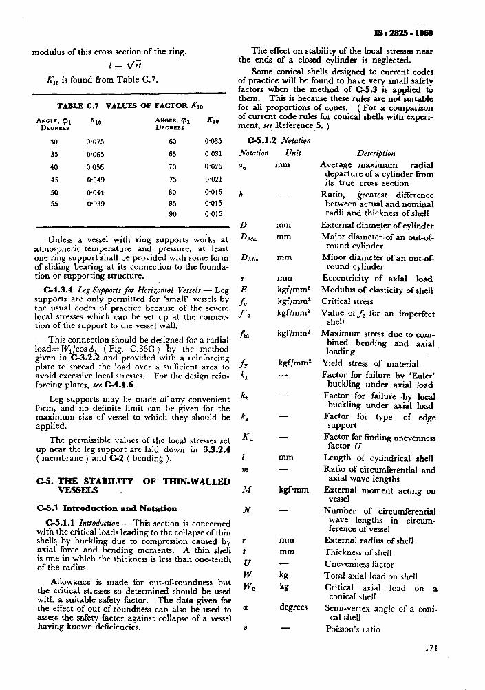
modulus of this cross section of the ring.
1= d/r>
X,, is found from Table C.7.
TABLE C.7 VALUES OF FACTOR &J
Azzsl KlO ANGEE, @l n;o
DEGREES
30 0.075 60 0.035
35 0.065 65 0.031
40 0 056 70 0.026
45 0.049 75 0.021
50 O-044 80 O-016
55 0.039 85 0.015
90 0.015
Unless a vessel with ring supports works at atmospheric temperature and pressure, at least one ring support shall be provided with scme form of sliding bearing at its connection to the founda- tion or supporting structure.
C-4.3.4 L.eg Su@orts for Horizontal Vessels - Leg supports are only permitted for ‘small’ vessels by the usual codes of practice because of the severe local stresses which can be set up at the connec- tion of the support to the vessel wall.
This connection should be designed for a radial load= Wr/cos +r ( Fig. C.36C ) by the method given in C-3.2.2 and provided with a reinforcing plate to spread the load over a sufficient area to avoid excessive local stresses. For the design rein- forcing plates, see C-4.1.6.
Leg supports may be made of any convenient form, and no definite limit can be given for the maximum size of vessel to which they should be applied.
The permissible values of the local stresses set up near the leg support are laid down in 3.3.2.4 ( membrane ) and C-2 ( bending ).
C-5. THE STABILrTy OF THIN-WALLED VESSELS
C-5.1 Introduction ‘and Notation
C-5.1.1 Introduction -- This section is concerned with the critical loads leading to the collapse of thin shells by buckling due to compression caused by
IS*28254968
The effect on stability of the local stresses near the ends of a closed cylinder is neglected.
Some conical shells designed to current codes of practice will be found to have very small safety factors when the method of C-5.3 is applied to them. This is because these rules are not suitable for all proportions of cones. ( For a comparison of current code rules for conical shells with experi- ment, se! Reference.5. )
C-5.1.2 Notation
,Votation
=.a
Unit
mm
b -
mm mm
mm
FT/rnrnz
kgf/mm*
kgf/mm2
kgf/mm2
kgf/mms -
-
-
-
mm -
kgfmm
-
mm
mm -
kg
kg
degrees
axial force and bending moments. A thin shell t is one in which the thickness is less than one-tenth of the radius.
,.,
Allowance is made for out-of-roundness but W
the critical stresses so determined should be used w
0
with a suitable safety factor. The data given for the effect of out-of-roundness can also be used to Q assess the safety factor against collapse of a vessel having known deficiencies. V -
Description
Average maximum radial departure of a cylinder from its true cross section
Ratio, greatest difference between actual and nominal radii and thickness of shell
External diameter of cylinder
Major diameter.of an out-of- round cylinder
Minor diameter of an out-of- round cylinder
Eccentricity of axial load
Modulus of elasticity of shell
Critical stress
Value off, for an imperfect shell
Maximum stress due to com- bined loading
bending and axial
Yield stress of material
Factor for failure by ‘Euler’ buckling under axial load
Factor for failure by local buckling under axial load
Factor for type of edge support
Factor for finding unevenness factor U
Length of cylindrical shell
Ratio of circumferential and axial wave lengths
External moment acting on vessel
Number of circumferential wave lengths in circum- ference of vessel
External radius of shell
‘Thickness of shell
Unevenness factor
Total axial load on shell
Critical axial load on a conical shell
Semi-vertex angle of a coni- cal Shell
Poisson’s ratio
171
c
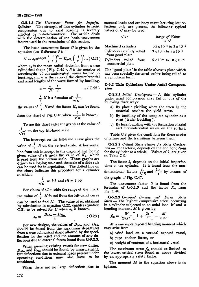
Is:2825- 1969
05.1.9 The Unevenness Factor for Impmfect Cylimfers - The strength of thin cylinders to resist compression due to axial loading is severely affected by out-of-roundness. The article deals with the determination of the basic unevenness factors used in the remainder of this section.
The basic unevenness factor U is given by the equation ( see Reference 3 ):
U = aom1*5N B(f)I=I&.ao(+~...(C.21)
where a, is the mean radial deviation from a true cylindrical shape ( Fig. C.45 ), Nis the number of wavelengths of circumferential waves formed in buckling, and m is the ratio of the circumferential and axial lengths of the wave formed by buckhng.
m= -$f- . . . ( c.22 )
$N is a function of - 4;
the values of GN and the factor KU can be found
1 from the chart of Fig. C.46 when _
drt is known.
To use this chart enter the graph at the value of
-&, on the top left-hand scale.
The intercept on the left-hand curve gives the
value of $ .N on the vertical scale. A horizontal
line from this intercept to the diagonal line for the given value of r/l gives the value of K, which is read from the bottom scale. These graphs are d ’ wn to a log-log scale and the scale of a slide rule
$ n be used for interpolation. The dotted line on
he chart indicates this procedure for a cylinder in which:
d+= 7.8 and r/l = 1.36
For vlaues of r/l outside the range of the chart,
the value oft N found from the left-hand curve
can be used to find JV’. The value of m, obtained by substitution in equation C.22, enables equation C.21 to be solved for U ihen a, is known.
a,= &ia -- D sir
4 . ..( C.23)
For new designs, the values of DM_ and DM~,, should be found from the maximum departures from a true cylindrical shape allowed by the speci- fication for the vessel and the amount of any de- fiections due to external forces found from C-3.2.8.
When assessing-existing vessels for new duties, DMW and DMin should be found by measurement, but deflections due to external loads present under operating conditions may also have to be considered.
When there are no large deflections due to
172
external loads and ordinary manufacturing imper- fections only are present, the following typical values of U may be used:
Gl.SG Range of Values of U
Machined cylinders 1.5 x 10-d to 3 x IO-’ Cylinders carefully rolled 3x10⁻⁴ to5x10-‘
from good p!ate Cylinders rolled from 5x IO-4 to 10x IO-4
commercial plate
The ‘ good plate ’ in the table above is plate which has been specially flattened before being rolled to a cylindrical form.
C-5.2 Thin Cylinders Under Axial Compres- sion
C4.2.1 Initial Development - A thin cylinder under axial compression may fail in one of the following three ways:
a) By plastic yielding when the stress in the material reaches the yield stress.
b) By buckling of the complete cylinder as a strut ( Euler buckling ).
c) By local buckling with the formation of axial and circumferential waves on the surface.
Table C.8 gives the conditions for these modes of failure and the transitions between them.
C-5.2.2 Critical Stress Factors for Axial ComprcJ- sion - The factor k, depends on the end conditions for the cylinder as a whole. Values of k, are given in Table C.9.
The factor k? depends on the initial imperfec- tions of the cylinder. It is found from the non-
dimensional factors & and F by means of
the graphs of Fig. C.47.
The unevenness factor U is found from the formulae of C-3.1.3 and the factor KU from Fig. C.46.
c5.2.3 Combined Bending and Direct Axial Stress - The highest compressive stress occurring in a cylinder subjected to an axial load W and a bending moment M is given by:
fm = &[1+~]+s- M is any superimposed bending moment which
may arise from: a) wind load on a vertical exposed vessel,
b) pipe anchor forces, or c) weight of contents of a horizontal vessel.
The maximum stress fm should be limited to the lowest critical stress found as above divided by an appropriate safety factor.
The moment M in the equation above is in kgf.mm.
05.3 Std$lityofConicalShe~e ‘above should be multiplied by the imperfection
C&3.1 Local Buckling Unhr Axial Compession - factor kz foutrd as in C-5.2,2 for the mean. value
h ideal right circular frustum of a cone of cons- tam thickness t and semi-vertex angle a will fail
of f.
by local buckling under a critical load given by:
2 x Eta cos2rx For a complete cone this is equal to &; for
W, 55 -_?z= t/3(1--v”) a frustum of radii r, and r,, + *I + r
= --z-- * when- W,, z 7.75 x 10*t2 co& for mild steel
( Retizrence 4 ). The unevenness factor U is found as in CS1.3, by taking I equal to slant height of the cone or
For imperfect cones the value of W, found as frustum.
Em, C.45 EXAMPLE OS OUT-OF-ROUND CYLINDERS
lO.0' 0*6 0'7 O-6 0'
(I*0
6.0
S-0
L*O
?N 3-O
Unevcnncdn Factor U - X0 00 t Q ( 1 7
FIG. CA6 CHART POR FINDING FAOTOR KO
173
xs:2825-1969
MODEOP FAILURL
Critical stress
Conditions
Plastic yielding to Euler Buckling
For mild steel For mild steel
TABLE C.8 COMPARISON OF MODES OF FMLURE
(Claurcs C-5.1.3 clnd C-5.2.1 )
PLASTIC EULER YreLorNo BUCKLING
LOCAL Bucrir~o
fa =fr
transition between
Euler buckling to local buckling
modes of -_ failure
Plastic yielding to local buckling
For mild steel
-+ < 6.15 $q; I
Refcwncc 2, Chapters II and IS; and Refcrexc 3.
0.001 92 -- :vy
TABLE C.9 CRITICAL STRESS FACTOR kI FOR C-6. REFERENCES
AXIAL COMPRESSION 1
( Clause c-5.2.2 )
END CONDITION c------- &.-___-..__,
End ! Eild 2
Clamped Free
Simp!y supported Simpiy supported
Clamped Simply supported
Clamped Gampcd
4
0.25
1-o
2.0 4.0
&as~c~. Handbook of engineering funda- mentals.
T:MOSHEAKO (S). Theory of elastic stability. 1961. Ed 2 1McGraw Hill, New York.
DONNELL (L H) and WAN (C C). Effect of imperfections on buckling of thin cylinder under axial commession. Joarnal oj Applied Mechakr, March i 950.
I i -- -- BUCKLING STARTED BV
YIELDING
0 O-02 0.04 0.06 0.08 0.1 0.12 044 046 0*18 ( 2
FIG. CA7 CHART FOR FINDING FACTOR K,
174
4.
5.
6.
7.
8.
9.
10.
11.
12.
13.
14. Fro. C.48
SErnE (P). Axi-symmetrical buckling of cir- cular cones under axial compression. 3ournal of Applied Mechanics, December 1956; P 625.
1 5
HERB and LEYLAND. Conical vessels subject to ejrternal pressure. Trans. I. Gem. E. 30. 1952. 65-74. 16.
Sm~on (K). Pressure vessel manual. 1942. Edwards Bras, USA.
Fm~sa (C E), Vibrations of vertical pressure 17.
VeSScls. 3ournal of EngineeGg for Industy, February 1959.
BIJLMRD (P P) . Local stresses in spherical 18. shells from radial or moment loadings. Welding 3ourn4 May 1957, Research Supple- ment (USA).
BIJUARD (P P) . On the stresses from local loads on spherical pressure vessels and 19. pressure vessel heads.. Welding Research CoutuiC Bulletin ,No. 34, March 1957 (USA).
Br LAARD (P P). Stresse.+ tiiom radial loads on cy mdrical pressure vessels. i* T$e Welding 20. Journal. Vol 33, 1954. P 615S-623s.
APPEND1 X D
BIJLMRD (P P). Stresses from radial loads. and external moments in cylindrical pressure vessels. The Welding Journal, December 1955. P 6083-617s.
HOFF (N J), KEMPNER (J), NARDO (S V) and POHLE (F V). Deformation and stresses in circular cylindrical shells caused by pipe attachments. Part I: Summary of investi- gation. Knolls Atomic Power Laboratory, Schenectady, N. Y. Report No. KAPL-921, November 1953.
HOFP (NJ), KEMPNER (J) and POHLE (P V). Line load applied along generators of thin- walled circular cylindrical shells of finite length. Q Appl. Math. Vol XI No. 4, January 1954. P 41 l-425.
KEMPNER (J), SHENG (J) and POHLE (FV). Tables and curves for deformation and stres- ses in circular cylindrical shells under localized loadings. Joumal of the Aeronautical Sciences, February 1957. P 119-129.
SHOESSOW (G J) and KOOISTRA (L F). Stresses in a cylindrical shell due to nozzle or pipe connection. Tram ASME, 67, A-107 (1945).
GARTNER (A I). Nomograms for the solution of anchor bolt problems. Petroleum Rejiner, July 1951.
BIJLAARD (P P) and CRANCH (E T). Stresses and deflections due to local loadings on cylindrical shells. Welding Journal Research Supplement, July 1960.
WEIL (N A) and MURPHY (J J). Design and analysis of welded pressure vessel skirt supports. Journal of Engineering for Industry, February 1960.
ZICK (L P). Stresses in large horizontal cylindrical pressure vessels on two saddle supports. Welding Journal Research Supplement. September 195 1.
KETCHUM (M S). The design of walls, bins and grain elevators. McGraw Hill, 1929.
( Clauses 2.3, 3.1 and 3.8.2 )
TENTATIVE RECOMMEND ED PRACTICE FOR. VESSELS REQUIRED TO OPERATE AT LOW TEMPERATURES
D-l. GENE&U described as the transition temperature, depends upon the material, method of manufacture, pre-
D-l.1 The ductility of some metals, including the vious treatment and the kind of stress system pre- carbon and low ahoy steels referred to in this sent. Fracture occurs at temperatures above the standard, is significantly diminished when the transition temperature only after considerable operating temperature is reduced below some cri- plastic strain or deformation. Whilst below the tical value. The critical temperature, commonly transition temperature, fracture may take place
175
IS : 2825 - 1969
ir! a brittle manner with little or no deformation. Brittle fractures are likely to be extensive and may lead to catastrophic fragmentation of a vessel.
D-1.2 It is beli:ved that the transition temperature of any given material is raised as the stress system approaches a uniform triaxial tensile state. Fur instance, material which has failed--~ by brittle fracture w;ll usually be found to show normal ductility, even at temperatures below that at which failure occurred, in a standard tensile or bend test, but similar specimens, if notched before testing, would be quite likely to break in a brittle manner. Thus constructional features producing a notch effect or sudden change of section are particularly objectionable in vessels designed for low temperature operation, since they may create a rtate of stress such that the material will be incapable of relaxing high localized stresses by plastic: deformation. For this reason the pro- perty of interest is described as notch ductility.
D-1.3 Many tests to determine the notch ductility of stee!s have been proposed but none has as yet been completely correlated with service ex- perience. The most convenient test is as given in IS : 1757-1961*.
D-L.4 In most of the tests currently used to deter- mine notch ductility the transition from ductile to brittle behaviour takes place over a range of temperature rather than at a single temperature. It is considered that an impact value of 2 kgf.m as determined by the method prescribed in IS : 1757-1961* at the service temperature will have adequate notch ductility for use in fusion- welded pressure vessels.
D-1.5 Notch ductility is an extremely variable property of steel and mild steel, in thicker plates, made in accordance with current specifications for steel for pressure vessel construction may show a Charpy 2 kgf.m ‘V’ notch transition temperature higher than normal atmospheric temperature. The safe record of the use of such steels shows that materials regarded as notch brittle can be used satisfactorily if the design working stresses, cons- truction, and workmanship are suited to the pro- perties of the particular material. Thus it is apparent that notch ductility is not necessarily an absolute requirement for all materials to be used for the manufacture of pressure vessels.
D-l.6 Consideration of service experience and the large amount of experimental work carried out confirms that brittle failures are not likely to occur except when both the following conditions occur simultaneously:
a) The material exhibits very little n@ ductility at the service temperature; and
b) A tensile force, which may be produced by applied loads or residual stresses, of a mag, nitude sufficient to cause plastic deformation is present at an existing Crack or other se- vere notch. A brittle fracture will not propagate unless the general tensile mem-
~- *hlcthodfor beam impact test ! V-notch ) on steel.
176
brane stress is sufliciently high to supply the necessary energy. Thus vessels in refri- gerant service will not normally require any special precautions where the operat- ing pressure is temperature dependent and hoop stresses are ,small at operating tem- peratures.
It is considered that the first condition will be eiiminated when the reievant impact tested ma- teriai is used; the second condition will not occur in vessels designed and constructed in accordance with the req-iremcnts of this standard except possib!y adjacent to welded seams in vessels not stress-relieved.
D-l.7 After consideration of these factors, it is recommended that the following minimum re- quirements should be satisfied in vessels designed to operate at low temperatures. It is recommended that manufacturers .carry out preliminary tests to confirm that the properties-especially notch ductility-of the materials used will not be damag- ed by treatments involved in the fabrication of
re vessel. Tests to determine the characteristics of welding electrodes should take into account the effect of variations in welding position and the effect of scatter of results should be considered.
D-2. MATERL4LS AND DESIGN STRESSES
D-2.1 Materials anu design stresses shall be in accordance with the requirements of Tables D.1 and D.2.
D-2.1.1 Because the liability of a given material to brittle fracture depends on the stress level and in some vessels because of the service conditions pressure at low temperatures is necessarily much lower than that at, for instance 0°C two cases are considered:
4 That in which the pressure at the sub-zero design temperature is not less than that which would be permitted for the vessel at 0°C by this standard; and
b) That in which the pressure at low tempera- tures will be considerably below the pres- sure permitted at 0°C (for ,example, in refrigerating equipment ).
D-2.2 Operating Pressure at Low Tempera- ture Equal to Design Pressure at 20°C - l%ble D.l sets out the limits of operating temnera- ture for vessels designed in accordance with 3 at stress levels in accordance with 2.2 (see alla Table D.2 ). These limits are dependent on the grade of steel, the thickness of the steel where it is wetded and whether the vessel is stress-relieved.
D-2.3 Operating Pressure at Low Tempera- ture Less Than Design Pressure at 20°C - Special considerations govern equipment which normally operates at low temperatures and pres sures but is necessarily designed to withstand the pressure which may arise, for instance, during shut-down periods, when the equipment warms up and the-vapour pressure of the contents rises.
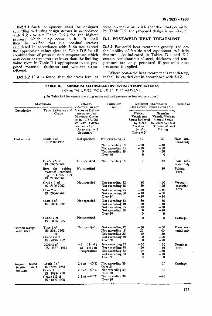
D-2.3.1 Such equipment shall be designed according to 3 using design stresses in accordance with 2.2 (see also Table D.2 ) for the highest pressure which may occur in it. It shall then be verified that the nominal stresses calculated in accordance with 3 do not exceed the appropriate values given in Table D.2 for all combinations of pressure and temperature which may occur at temperatures lower than the limiting value given in Table D.l appropriate to the pro- posed material, thickness and whether stress- relieved.
D-2.3.2, If it is found that the stress level at
IS : 2825 - 1969
some low temperature is higher than that permitted by TabIe D.2, the proposed design is unsuitable.
D-3. POST-WELD HEAT TREATMENT
D-3.1 Post-weld heat treatment greatly reduces the liability of ferritic steel equipment to brittle fracture. As indicated in Tables D.l and D.2 certjin combinations of steel, thickness and tem- perature are only permitted if post-weld heat treatment is applied.
Where post-weld heat treatment is mandatory, it shall be carried out in accordance with 6.12.
TABLE D.1 MINIMUM ALLOWABLE. OPERATING TEMPERATURES ( Clauses D-2.!, D-2.2, D-2.3.1, D-3.1, D-5.1 and D-6.5 )
( See Table D.2 for vessels operating under reduced pressure at low temperatures )
MATERIALS CHARPY
r---- ------A-------7 V-NOTCH IMPACT Description Type, R;X;UX and VALUE I\S DETER-
MINEI) BY 7HE METHOD GIVEN IN IS : 1757-1961 AT TEST TEMPER-
ATURE IN kgfm (AVERAGE OF 3
Carbon steel Grade 1 of IS : 2002-1962
SPECIMENS )
Not specified
Grade 2A of IS : 2002-1962
Bars for bolting, material conform- ing to Grade 1 of IS : 2100-1962
Grade 1 of IS : 2100-1962
Class 2 of IS : 2004-1962
Class 3 of IS : 2004-1962
Grade 2 of IS : 3038-1965
C;w&m~inga- Type 2 of IS : 2041-1962
Grade 2gof IS : 2002-1962
20Mn2 of IS : 4367 - 1967
Impact t;tteet ferritic castings
Grade I of IS : 4899- 1968
Grade II of IS : 4899-1968
Grade III of IS : 4899- 1968
Not exceeding 12
Not exceeding 18 Not exceeding 25 rv;;yeeding 30
Not specified
Not specified
Not exceeding 16
-
Not specified
Not specified
Not exceeding 12 Not exceeding 18 Not exceeding 25 %&c,ccding 30
,
Not exceeding 12 Not exceeding 18 Not exceeding 25 Not exceeding 30 Over 30
Not specified -
Not specified
4.8 ( Izod ) at room tcmpcraturc
Not exceeding 12 Not exceeding 18 Not exceeding 25 Not exceeding 30 Over 30 Not exceeding 12 Not exceeding 18 Not exceeding 25 Tv;y3yding 30
pl at -40°C
21 at -50°C
2.1 at -60%
Not exceeding 30 Over 30 Not exceeding 30 Over 30 F;;yzeding 30
”
THICKNESS mm
MINIMUM ALLOWABLE REMARKI OPERATING TEMPERAXURE “C
r_--_--L-_ -----7 Welded Seamless
Vcss& not Vcsscls, Welded Stress-Relieved Vessels Strcss-
by Heat Relieved by Hea: Treatment Treatment and > See also
Table 6.3 )
-30
-20 -10
8
0
-30 -20 -10 -10 -30 -20 - 10
00
0
-30 -20 -10
0 0
-30 -20 - 10
00
Kolting
-50
-; -20
0
-30
-30
-60 -1-50
-: -10 -50 -40 -30 -20
0
0
-50 -40 -30 -20 -20 -50 -40 -30 -20
0
-20
-30
-40
Plate ma- terial only
Plate ma- terial only
Bolting bars
Wrought material only
Castings
Plate ma- terial only
Forgings only
Castings
177
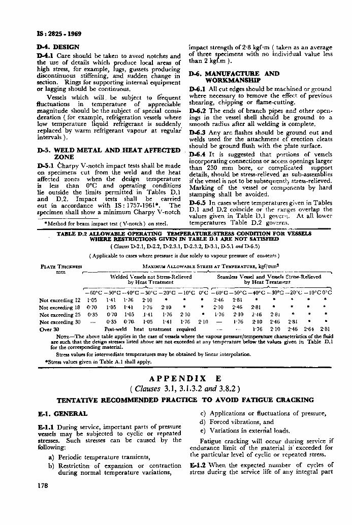
IS : 2825 - 1969
D-4. DESIGN D-4.1 Care should be taken to avold notches and the use of details which produce local areas of high stress, for example, lugs, gussets producing discontinuous stiffening, and sudden change in section. Rings for supporting internal equipment or lagging should be continuous.
Vessels which will. be subject ta fi%quent fluctuations in temperature of appreciable magnitude should be the subject of special consi- deration (, for example, refrigeration vessels where low temperature liquid refrigerant is suddenly replaced by warm refrigerant vapour at regular’ intervals ).
D-5. WELD METAL AND HEAT AFFECTED ZONE
D-5.1 Charpy V-notch impact tests shall be made on specimens cut from the weld and the heat affected zones when the design temperature is less than 0°C and operating conditions lie outside the limits permitted’ in Tables D.l and D.2. Impact tests shall be carried out in accordance with IS: 1757-1961*. The specimen shall show a minimum Charpy V-notch
*Method for beam impact test ( V-notch) on steel.
impact strength of 2-8 kgf-m ( taken as an average of three specimens with no individual value less than 2 kgf.m ).
D-6. MANUFACTURE AND woRKMANsHlP
D-6.1 All cut edges should be machined or ground where necessary to iemove the effect of previous shearing, chipping or flame-cutting. D-6.2 The ends of branch pipes and other open- ings in the vessel shell should be ground to a smooth radius after all welding is complete. D-6.3 Any arc flashes should be ground out and welds used for the attachment ef erection cleats should be ground flush with the plate surface. D-6.4 It is suggested that portions of vessels incorporating connections or access openings larger than 250 mm bore, or complicated support details, should be stress-relieved as sub-assemblies if the vessel is not to be subsequentag stress-relieved. Marking of the vessel or components by hard stamping shall be avoided. D-6.5 In cases where temperatures given in Tables D.l and D.2 coincide or the ~a.age:s overlap the values given in Table D.l govern, At all lower temperatures Table D.2 governs.
TABLE D.2 ALLOWABLE OPERATING TEMPERATURE/STRFSS CONDITION FOR lR%ELS WHERE RESTIUClTONS GIVEN IN TABLE D.l ARE NOT SATISFIED
( CIalrrcs D-2.1, D-2.2, D-2.3.1, D-2.3.2, D-3.1, D-5.1 and D-6.5)
( Applicable to cases where pressure is due solely to vapour pressure of cozrtents )
PLATE THICKNESS M~V~IMUM ALLOWABLE STRESS AT TEMPERATURE, kgf/m& mm < --- -_--__~---_----~__-_.____ ,
Welded Vessels not Stress-Relieved Seamless Vessel and Vessels Stress-Relieved by Heat Treatment by Heat Treatment
c-__--.------_-- A ‘--~-~------/ -60°C -50°C -40°C -30°C -20°C - 1O’C Oc; r6O”C -50°C -40°C -30% -20°C -10°C O’C
Not exceeding 12 1.05 1.41 l-76 210 * * l 246 2.81 * * * * *
Not exceeding 18 @70 1905 1.41 1.76 ?lO * * 210 2.46 2.8, rl * + *
Not exceeding 25 @35 0.70 1.05 A.41 1.76 210 * 1.7l.i 210 2.46 281 + * *
Not exceeding 30 - 0.35 078 1.05 1.41 1*7G 2.10 - 1.76 2.10 246 2’81 * *
Over 30 Post-weld heat treatment required - - 1.76 2.10 246 2-64 281
NOTE-The above table applies in the case of vessels where the vapour pressure/temperature characteristiw of the fluid are such that the design stresses listed above are not exceeded at any temperature below the valuca given in Table D.l for the corresponding material.
Stress values for intermediate temperatures may be obtained by linear interpolation.
*Stress values given in Table A. 1 shall apply.
APPENDIX E (Clauses 3.1, 3.1.3.2 and 3.8.2)
TENTATIVE RECOMMENDED PRACTICE TO AVOID FATIGUE CRACKING
El. GENERAL c) Applications or fluctuations of pressure,
El.1 During service, important parts of pressure d) Forced vibrations, and
vessels may be subjected to cyclic or repeated e) Variations in exter&al loads.
stresses. Such stresses can be caused by the following:
Fatigue cracking will occur during service if endurance limit of the material is’ exceeded for
a) Periodic temperature transients, the particular level of cyclic or repeated stress.
b) Restriction of expansion or contraction El.2 .When the expected number of cycles of during normal temperature variations, stress during the service life of any integral part
178
IS:2825-1969
of a pressure vessel may exceed the endurance limit, the level of cyclic stress and/or the expected number of cycles Should be reduced to fall reasonably within the limit.
El.3 Corrosive conditions are detrimental to the endurance of the vessel material. Fatigue cracks may occur under such conditions at low levels of fluctuation of applied stress. Since the tensile strength of a steel has little or no effect upon the fatigue strength under corrosive conditions the use of high strength steels in severe corrosion fatigue service will offer no advantage unless the surface is effectively protected from the corrosive medium. Where corrosion fatigue is anticipated it is espe- cially desirable to minimize the range of cyclic stresses and carry out inspection at sufficiently frequent intervals to establish the pattern of
ehaviour.
$ I.4 A detailed analysis of the cyclic stresses in a /pressure vessel and interpretation in terms of satisfactory service life is usually tedious and time consuming. When such estimates are required, the purchaser should inform the manufacturer. The manufacturer should arrange for the cal- culations to be made, the purchaser having access to any part of the calculations relating to the final assessment.
El.5 There is a lack of data on the influence of creep on the endurance of the construction ma- terial under cyclic stress. Where a pressure vessel is intended for cyclic operation within the creep range of the material, the range conditions should be agreed between the purchaser and the manufacturer having regard to the available service experience and experimental information.
El.6 The following notes relate to pressure vessels which operate at temperatures below the creep range of the material of construction:
a) In general, a detailed analysis need not be made when the design is based on previous and satisfactory experience of strictly comparable service;
b) A fatigue test or tests have been made to demonstrate the reliability of the design;
c) The recommendations which are detailed in the following parts of this section are satisfied; and
d) Where strains have been determined ex- perimentally and shown to be below the endurance limit for the required life.
E-2. PRESSURE CYCLING
E2.1 A cycle of pressure !oading is represented by either each loading and unloading of a vessel or any single pulsation or fluctuation of pressure.
E2.2 For a vessel which operates at constant pressure and at a steady temperature below the creep range for the material, the expected number of cycles .N due to start up and shut. down during the life of the vessel should not exceed:
N= [I l-4( 3000 1 T) *
2K.fr - f 1 . . . (E.1)
where
7-Z
f=
Ii-=
fr=
E-2.3 Where is not known,
the temperature in “C corres- ponding to application of the cyclic or repeated stress;
the design stress in kgf/mms at a temperature of T”C;
the theoretical stress or strain con- centration factor of any opening, attachment, etc; and
the range of nominal cyclic stress in kgf/mm”.
the stress concentration factor K a value of 4 may be assumed. In __. _
no case shall K be taken as less than 2.
E2.4 For a pressure vessel which is subjected to pressure fluctuations in addition to the conditions defined in E-2.2, the requirement is that:
$;+ 3;+-$- +-$+...etc dl*O... (E.2)
where
n19 % % n,, etc, are the expected numbers of cycles of stress for the ranges of pressure fluctuations; and
N,, .N,, Ns, N,, etc, are the limiting numbers of cvcles .calculated bv eauation (E. 1) for the cT;;e;;ding )anges . of cyclic stress 2&X
whrch gave
- < 1.1 may be neglected ). f
E2.5 The ratio of the expected number of cycles to the limiting number of cycles of stress for start-
ups and shut-downs of the pressure vessel should be included in equation E.2. However, cycles due to pressure tests can be neglected.
E3. CYCLIC THERMAL STRESSES
E3.1 Pressure vessels which operate at elevated or sub-zero temperatures should be heated or cooled slowly and should be efficiently lagged to minimize temperature gradients in the shells. Rapid changes of shell temperature should be avoided during service.
The vessels should be able to expand and con- tract without undue restraint.
E-3.2 ,Provided the above conditions are observed estimates of thermal stresses due to temperature changes need not be specially considered. Where slow rates of heating and cooling cannot be em- ployed or temperature transients during service may cause rapid local heating or cooling, the following limitations are recommended:
4
b)
During start-up and shut-down the difference in temperature within a distance equal to twice the thickness of the shel.1 should not exceed 6O“C near disconti- nuities or 150% at uniform sections. Temperature differences due to temperature transients repeated periodically during service should be limited to similar levels.
179
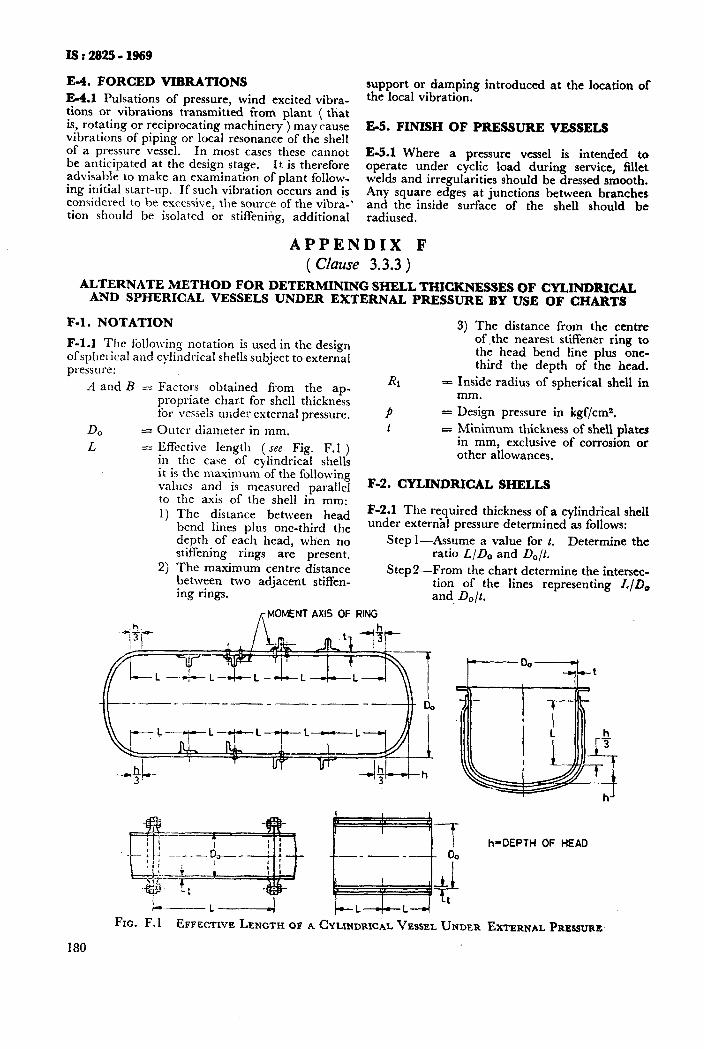
IS : 2825 - 1969
E-4. FORCED VIBRATIONS
E-4.1 Pulsations of pressure, wind excited vibra- tions or vibrations transmitted irom plant ( that is, rotating or reciprocating machinery ) may cause vibrations of piping or local resonance of the shell of a pressure vessel. In most cases these cannot be anticipated at the design stage. It is therefore advisable to make an examination of plant follow- ing initial start-up. If such vibration occurs and is considered to be excessive, the source of the vibra-’ tion should be isolated or stiffening, additional
support or damping introduced the local vibration.
at the location of
E-5. FINISH OF PRESSURE VESSELS
E-5.1 Where a pressure vessel is intended to operate under cyclic load during service, fillet welds and irregularities should be dressed smooth. Any square edges at junctions between branches and the inside surface of the shell should be radiused.
APPENDIX F ( Clause 3.3.3 )
ALTERNATE METHOD FOR DETERMINING SHELL THICKNESSES OF CYLINDRICAL AND SPHERICAL VESSELS UNDER EXTERNAL PRESSURE BY USE OF CHARTS
F-l. NOTATION 3) The distance from the centre
F-l.1 The follolving notation is used in the design of the nearest stiffener ring to
ofspherical and cylmdrical shells subject to external the head bend line plus one-
pressure: third the depth of the head.
-4 and B - Factors obtained from the ap- & s Inside radius of spherical shell in
propriate chart for shell thickness mm.
for vessels under external pressure. P = Design pressure in kgf/cms.
D0 = Outer diameter in mm. t = Minimum thickness of shell plates
L = Effective length ( see Fig. F.l ) in mm, exclusive of corrosion or
in the case of cylindrical shells other allowances,
it is the maximum of the following values and is measured narallel F-2. CYLINDRICAL SHELLS
180
the axis of the shell i; mm: The distance betl,.een head F-2.1 The required thickness of a cylindrical shell
bend lines nlus one-third the under external pressure determined as follows:
depth of each head, when no Step I-Assume a value for t. Determine the stiffening rings are present. ratio L/D, and Dolt. The maximum centre distance between two adjacent stiffen-
StepP-From the chart determine the intersec-
ing rings. tion of the lines representing L/Do and, Do/t.
,+4OMENT AXIS OF RING
I---- L ------a./ t--L--+--L4 -
FIG. F. 1 EFFECTIVE LENGTH OF A CYLINDRICAL VESSEL UNDER
h-DEPTH OF HEAD
EXTERNAL PRESSURE
Step 3-From this intersection point move vertically to the material line for the design temperature.
Step 4-Find the value of Factor 3 correspond- ing to this point of intersection. Compute the allowable working pres-
sure pa by formula pB = B=
14*220,/t kgf/cm* and compare with p. Choose a value of t that will make pB >p.
F-3. SPHERICAL SHELLS
F-3.1 The required thickness of a spherical shell under external pressure determined as follows:
Step l-Assuming a value of t, determine the ratios of Rllt and RijlOO t.
Step P-Enter the left-hand side of the chart at the value of Ri / 100 t d,etermined from Step l and move hortzontally to the line marked ‘ Sphere Line ‘.
Step S-From this intersection move vertically to the material line for the design tem- perature.
Step 4-Find the value of Factor B correspond- ing to this point of intersection.
Step 5-Compute the allowable working pres-
sure pn by the formula pa = -- --c--- 14.22RJt
kgf/cm2 and compare with p. Choose a value of t that will make pe > p.
F-4. STHWENING RINGS FOR VESSELS UNDER EXTERNAL PRESSURE
F-4.1 Intermediate stiffening rings composed of structural shaped welded to the inside or outside of the shell shall have a moment of inertia about its neutral axis through the centre of gravity section parallel to the axis of the shell, I, not less than that determined by the formula:
I, = Do2L (t+A,/L) x FactorA ... Fl _.-__.~~-----~- -
14 x l-04
where
I, = required moment of inertia of the stiffening ring in mm4;
A, = cross-sectional area of stiffening ring mm’; and
L = one-half the distance from the centre line of one stiffening ring to the next line of support on one side, plus one-half of the centre line distance to the next line, if any on the other side of the ring. All the distances are parallel to the axis of the shell and are in mm.
a) Line of support is ( see Fig. F. 1 ) :
1) anotherstiffening ring,
IS : 2825 - 1969
2) a circumferential connection to a ,jacket, and
3) a circumferential line on a head at one- third the depth of the head from the head bend line.
The required moment of inertia for a stiffening ring shall be determined as follows:
Step l--Select a member to be used for the stiffening ring. Let its moment of inertia be 1.
Step2-Calculate Factor B by the formula
Factor L3 = - ‘g” x 14.22 -- t + As
11- . . . F.2
and find the point corresponding to this value of B OJI the material line for the design temperature.
Step 3-Find the value of Factor -4 corrcspond- inq to this point on the material line.
Step&-Determine the required moment of inertia I, from equation ( F. 1 ) using the value of that factor A as de- termined above. Compare this value of I, with I and choose a section such that its moment of inertia is greater than I#.
b) See 3.3.3.4 (c).
c) See 3.3.3.4 (d).
d) See 3.3.3.4 (e).
e) See 3.3.3.5.
F-5. CHARTS FOR DETERMINING SHELL THICKNESSES OF CYLINDRICAL AND SPHERICAL VESSELS UNDER EXTERNAL PRESSURE
Fig. F.2
Fig. F.3
Fig. F.4
Fig. F.5
Fig. F.6
Fig. F.7
Fig. F.8
Fig. F.9
Carbon and low alloy steel
04Crl9Ni9 Type of stainless steel
Austenitic stainless steels other than type 04Crl9Ni9
07Cr13 Type of 3taintess steel
99.5 Percent aluminium ( Grade IB )
.%luminium alloy ( Grade N3 )
Al-\lg ( 276 llg ) Alloy i Grade N4) Al-big ( 3.5:; ?clg ) Alloy ( Grade N5)
Fig. F-10 AI-Mg ( 4.5% AIg ) Alloy ( Grade N8)
Fig. F.ll Copper (sci IS: 1972-1961 )
Fig. F.12 i~luminium bronze ‘( see Grade ISABZT-IS : 1545-l 960 )
Fig. F. 13 70-30 Copper nickel alloy ( see Grade CuNiSlMnl Fe of IS : 2371-1963 )
Fig. F.14 Nickel
181
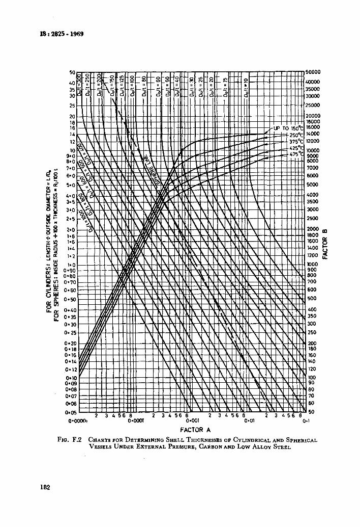
FACTOR A
Fro. F.2 CHARTS FOR DETERMINING SHELL THICKNESSES OF CYLINDRICAL AND SPHERICAL VESSELS UNDER EXTERNAL PRESSURE,CARBONAND Low ALLOY STEEL
182
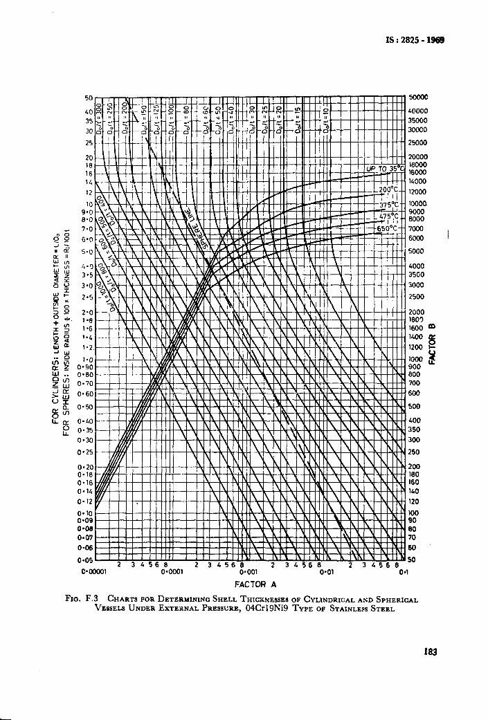
IS:2825-1968
C*OOOOl 0*0001 0.001
FACTOR A
FIG. F.3 CHARTS FOR DETERMININCISHELL THIWNESSES VESSELS UNDER EXTERNAL PRESSURE, 04Crl9Ni9
I6000 16000 14000
12000
10000 9000 6000 7000 6ooO
5000
4000 35co 3000
2500
2000 1803 1600 m 1400
8 1200 b-
Y too0 k 900 800 700 600
500
400 350 300
250
200 I60 160 140
120 100 90 80 70 60
50
O*Ol - 04
OF CYLINDRICAL AND SPHERICAL TYPE OF STAINLEPSSTEEL
183
I
IS:282511968
o*oooo1, O*cml O*ool O*Ol o-1
FACTOR A
FIG. F.5 CHARTS FOR DETERMINING SHELL THICKNESSES OF CYLINDRICAL AND SPHERICAL VESSELS UND~ZR EXTERNAL PRESSURE, 07013 TYPE OF STAINLESS STEEL
IS I 2829 - 1969
50 60000
40000 35000
30000
+ I ? I /-H-H I
0*00001 0.001 O*Ol 04 FACTOR A
FIG. F.7 CHARTS FOR DETF.RMINING SHELL THICKNESSES OF CYLINDRICAL AND SPHERICAL VESSELS UNDER EXTERNAL PRESSURE, ALVMINIVM ALLOY ( GRADE N3 )
187
ISr2825- 1969
FI
o-40
o-35
o-30
0*25
o-20 O-18 0.16
O-14
0.12
I 0'00001
3 45t! 0*0001 s = l oOl O*Ol
FACTOR A ro. F.9 CHARTS FOR DETERMININIO SHELL THICXNENSF,S OF CYLINDRICAL AND SPHERICAL
VESSELS UNDER EXTERNAL PRELIIURE, AI-Mg ( 3.5% Mg ) ALLOY ( GRADE N5 )
189
rs:2%2!5-1969
50000
40000
35000
30000
25000
20000 16000 16000
1~000
-12000
10000 9000 8000
7000
6000
LOO0
3500
3000
2500 Pp
2000 8 1800 I- 1600 2 1400 L
l-2 F'i i Xi iWtH 1200
l-0 0*90 0.80 0.70
0*60
0*50
0.40
O-35
0.30
O-25
0*20 0.18 0*16 0.14
0*12
oeia o-09 O-00 o-01
0.06
040001 0*0001 O*OOl 0.01 0.1
FACTOR A
Fxa. F. 10 CHARTS FOR DETERMININO SHELL THICKNESSES OF CYLLNDRICALAND SPHERICAL VESSELS UNDER EXTERNAL PRESSURE,AI-,Mg jl'5:; Mg) ALLOY {GRADE N8)
190
50000
1-o o-90 0.00
o-70
0.60
o-50
o-40
o-35
o-30
0.25
0.20 O-18 0.16
O-14
0*12
50 L 34560 2 34566 2 3 456 6
11' O*OOl O*Ol o-1
35000
30000
25000
18000
14000
12000
10000 9000 8000
7000
6000
5000
4000 3500
3000
2500
2000 1800 * 1600 a 1400 e
1200 y
JO00 L 900 000
700
600
400 350
300
,250
" 200 180 160
140
120
'100 90 80
70
60
FACTOR A
FIG. F.ll CHARTS FOR DETERMININQ SHELL THICKNESSES OF CYLINDRICAL AND SPHERICAL VESSELS UNDER EXTERNAL PRESSURE, COPPER (see IS : 1972-1961 1
191
1.6 1.4
O.bo" .
0.60 0'70
0.60. , , , , ,,,w ,I_ ,
0*10 o-35
0.30
0.25
0.20
-- 2 34568 2 34569 i‘ 3L560 0*001 0.01 0.1
FACTOR A
FIG. F.12 CHARTS FOR DETERMINING SHELL THICKNESSES OF CYLINDRICAL AND SPHERICAL VESSELS UNDER EXTERNAL PRESSURE, ALUMINWM BRONZE ( see GRADE ISABZT-IS : 1545-1960 )
192
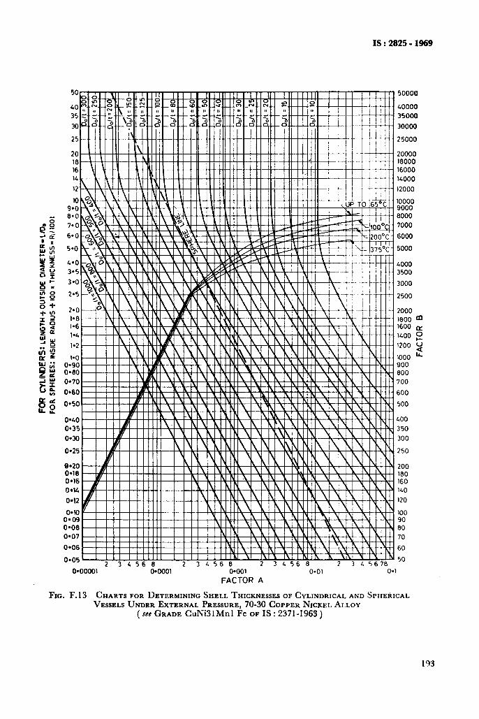
IS : 2825 - 1969
~ 5ooou
40000
35000
30000
25000
20000 16000 16000
14000
12000
0*00001 0*0001 0.001 O-01 O-
FACTOR A
8000
6000
5000
2500
2000 1600 * 1600 my
1400 2
1200 u
iooo iz
900 600
700
600
500
400
350
300
250
200 160 160 140
120
100 90 80
70
60
50
1
FIG. F.13 CHARTS FOR DETERMINING SHELL THICKNESSES OF CYLINDRICAL AND SPHERICAL VESSISLS UNDER EXTERNAL PRESSURE, 70-30 COPPER NICKEL ALLOY
(see GRADE CuNi31Mnl Fe OF IS : 2371-1963 )
193
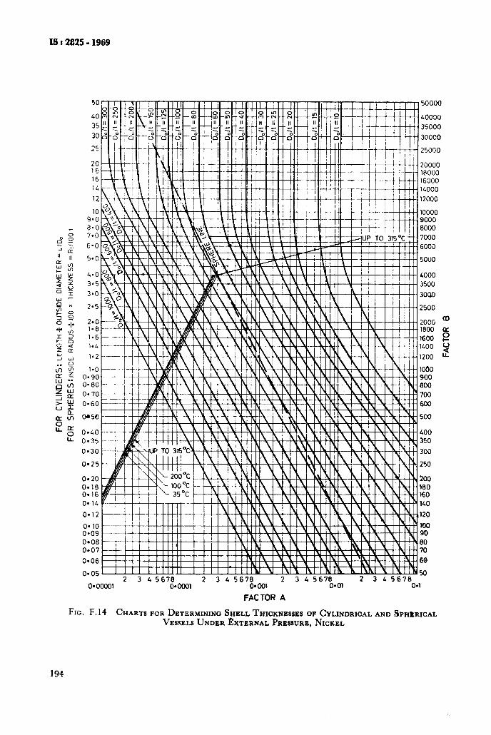
X8:2825-1969
TO! I 1 I I I II I II III I II III III I II I : II III I I I I I I I m50000
LOO00
35000
30000
25000
20000
16000
1200G
-- 2 3 45670 2 3 4 5670 2 345676 2 3 L 5678 0*00001 04ca 0.001 Q*Ol 04
FACTOR A
FIG. F.14 CHARTS FOR DETERMINING SHELL THICKNESSES OF CYLINDRICAL AND SPHZRICAL VESSELSUNDEREXTERNAL PRESSURE,NICKEL
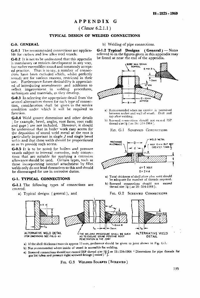
IS i 2825 - 1969
APPENDIX G
( m711se 6.2.1.1 )
TYPICAL DESIGN OF WELDED CONNECTIONS
G-O. GENERAL
G-O.1 The recommended connections are applica- ble for carbon and low alloy steel vessels.
G-O.‘2 It is not to he understood that this appendix is mandatory 01 restricts development in any way, but rather exernn!ifies sound and commonly accept- ed practice. That is to say, a number of connec- tions have been excluded w,hich, whilst perfectly souud; are for various reasons, restricted in their use. Furthermore future desirability is appreciat- ed of introducing amendments and additions to reflect improvement in lvelding procedures, techniques and materials, as they develop.
b) Welding of pipe connections.
G-l.2 Typical Designs ( General ) - Notes referred to in the figures given in this appendix may be found at near the end of the appendix.
G-O.3 In se!ecting the appropriate detail from’the several alternatives shown for each type of connec- tion, consideration shall be given to the service condition under which it will be required to function.
a)
G-O.4 Weld groove dimensions and other details ; for example, bevel, angles, root faces, root radii and gaps ) are not included. However, it should he understood that in boiler work easy access for the deposition of sound weld metal at the root is pnrticularly important in single J and single bevel wt-1;j.s and that these welds should be proportioned so as to provide such access.
G-O.5 It is to be noted for boilers and pressure vessels subject to internal corrosion, only connec- tions that are suitable for applying a corrosion allowance should be used. Certain types, such as those ;ncorporating internal attachment by fillet welds only do not lend themselves to this and should be discouraged for use in corrosive duties.
Ii~commended when no crevice is permitted between socket and wall of vessel. Drill nnd tap after welding.
b) Screwed connections sl~oultl not exceed ISP thread size 14 ( SCI IS : 25 I- 1964 ).
FIG. G. 1 SCREWED COMNECTIONS
0=2xd
G-l. TYPICAL CONNECTIONS
G-l.1 The following types of connections are covered:
a) Total thickness of shell plate plus weld should be adequate for number of threads required.
b) Screwed connections should not exceed thread size 14 (see IS: 554-1964).
a) Typical designs [ general ), and FIG. G.2 SCREWED CONNECTIONS
ALTERNATIVE WELO OETAlL (FOR DlMENSlDNS SEE F1G.G. 4)
THE WELDING PROCED’YIE SHALL BE SXH ALTERNATIVE WELD _ AS TO ENSURE SOUND POSiTlVE ROOT DETAIL
a) b) 4
PENETRATION IN THE JOINT
If the shell thickness f exceeds approx 15 mm, preference should be given to joint shown in Pig. G.1.
Not recommended where inside of vessel is accessible for welding.
gcmwed connections should not exceed ISP thread size If [see IS : 554-1964 ‘ Dimensions for pipe threads for gas list tubes and prcsaurc tight screwed fittinga ( rcviscd) ’ 1.
FIG. G.3 WELDED SOCKETS ( SCREWED )
195
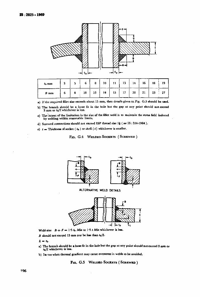
lsi2825-1969
13 1 14 1 16 ( 18 / 19 1
-k----- l--l-l-l 17 1 20 1 21 1 23 1 27 1
I I I I I
4
b)
4
4 4
If the required fillet size exceeds about 15 mm, then details given in Fig. G.5 should be used.
The branch should be a loose fit in the hole but the gap at any point should not exceed 3 mm or la/2 whichever is less.
‘l”he’intent of the limitation in the size of the fillet weld is to maintain the stress field induced by welding within reasonable limits.
Screwed connections should not exceed ISP &cad size 14 ( see IS : 554-1964 ).
t - ‘I’bickness of socket ( tp,) or shell ( t) whichever is smaller.
Fro. G.4 WELDED SOCKETS ( SCREWED )
ALTiRNATlVE WELD DETAILS
Weld size B + F I 1.5 tb Mia or l-5 f Min whichever is less.
B should not exceed 15 mm nor bc len than ta/2.
t = t,,.
a) The branch should be a loose fit in the hole but the gap at any point should not aceed 3 mm or ts/2 whichever is less.
b) Its use when thermal gradient may cause ovem in welds to be avoided.
Fm. G.5 WELDBD SOCKETS (SCREWED)
196
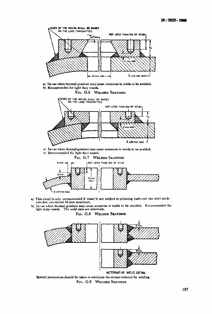
THE WLLOS SHALL Oli OASCO ON THE LOAD TRANSMITTEO
NOT LESS THAN OIA OF STUD-,
Its w when thermal gradient may cause overattess in welds to bc avoided. Recommended for light duty vessels.
Fm. G.G WELDED SEATINGS
OF THE WELDS Sl4Al.L BE BASE3 ON THE LOAD TRANSMITTED
NOT LESS THAN MA OF STUD,
Its use when thermal grad&t may cause oversiress in welds to be avoided. Recommended for light duty vessels.
FIG. G.7 WELDED SEATINGS
r NOT LESS THAN DIA OF STUD
~trlOmm,.,AX I
a) This detail iti only recommended if vessel is not subject to pulsating loads and the shell thick- ness does not exceed 10 mm maximum.
b) Its use when thermal gradient may cause overstress in weldr to be avoided. Recommended for light duty vessels. The weld sizes are minimum.
Fro. G.8 WELDED SEATINCM
ALTERNATIVE WELD DETAIL’
Special precautions,should be taken to minimize the stresses induced by welding.
Frtx.G.9 WELDED SEATINGS
197
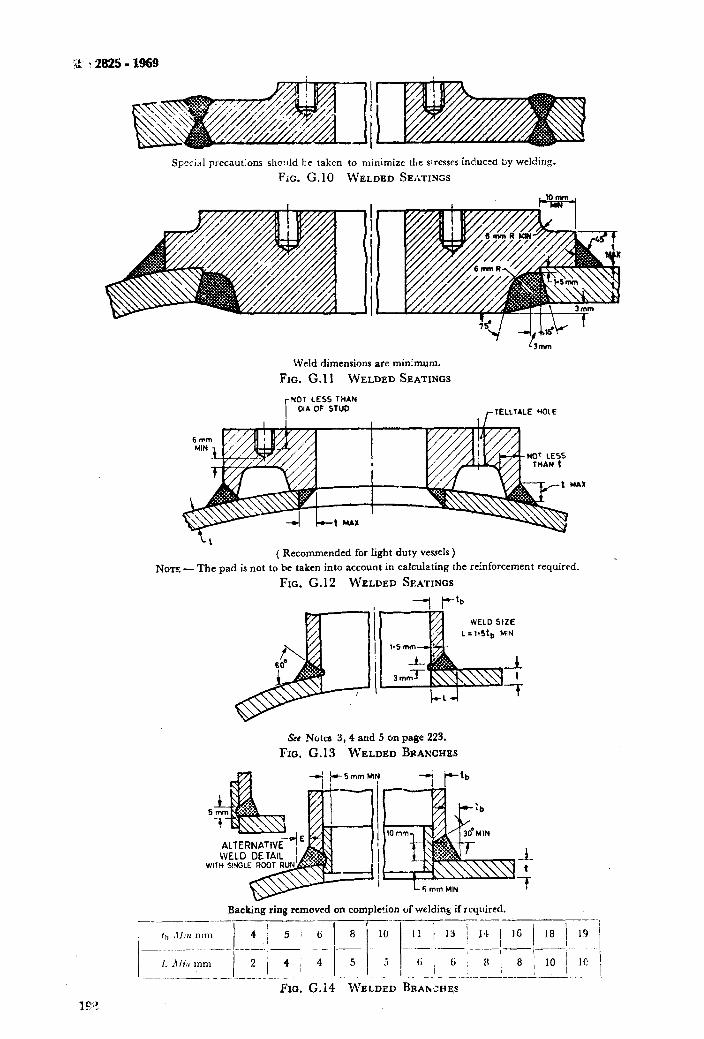
Special precaut:ons slmlld Le taken to minimize the s:resses induced by welding.
Fit. G.10 WELDED SEATINGS
Weld dimensions are minimum.
FIG. G.11 WELDED SEATINGS
NOT LESS THAN
OIA OF STUD j- TELLTALE HOt E
( Recommended for light duty vessels )
Now - mc pad is not to he taken into account in calculating the reinforcement required.
FIG. G. 12 WELDED SEATINGS
I ---I Stb
WELD SIZE
See Notes 3,4 and 5 on page 223.
FIG. G.13 WIELDED BRANCHES
-L
-;
Backing ring removed on compkc!ion of welding if rquircd. ;-_-_---_._--_- ._-___- __--
I,, .ll;tr 11,111 _ _... __-.__~_-- _---. - - -- .__ _-.__- -
I; n ibt mm 8 / 8 \;Fi IC __ .______ ._ ._ __ ___ ..-.
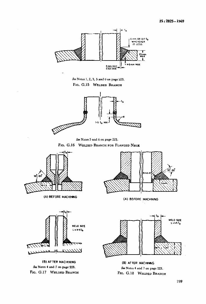
IS : 2825 - 1969
Set &Jotts 1,2,3, 5 and ci on page 223.
Fm. G.15 WELDED BRANCH
Scr Notes 5 and 6 on page 223.
Fro. G.16 WELDED-BIUNCH FOR FLANGED NECK
(A) BEFORE MACHINING (A) BEFORE MACHINING
(B) AFTER MACHINING
Sir Notes 4 and 7 on page’223.
FIG. G. 17 WELDED BRANCH
(6) AFTER MACHINING
See Notes 4 and 7 on page 223.
FIG. G. 18 WELDED BRANCH
199
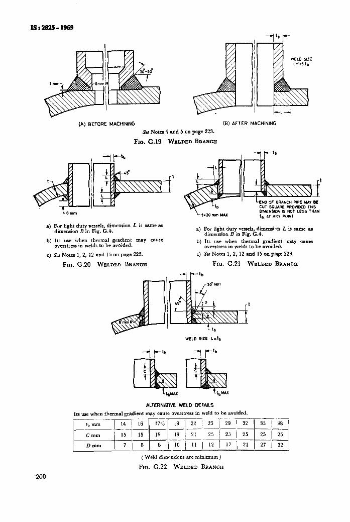
(A) BEFORE MACHINING IB) AFTER MACHINING
& Nom 4 and 5 on page 22%
Fxo. G.19 WELDED BRANCH
4
b)
i
I t i I
LENfJ 3f BRANCH PIPE NAV DE CUT SOUA’+E PROVIDED THIS
LESS THAN DtMNSY)N IS NO7 I tb AT ANY PilINT
For light duty vessels, dimension L is same as dimension B in Fig. G.4. a) For light duty vessels, dimensi-m t is same as
dimension B in Fig. G.4. Its use when thermal gradient may cause overstress in welds to be avoided.
b) Its use when thermal gradient may cause overstress in welds to be avoided.
c) See Notes 1,2, 12 and 15 on page 223. c) See Notes I, 2, 12 and 15 on page 223.
Fro. G.20 WELDED BRANCH Fm. G.21 WELDED BRANCH
WELD SlZE L=tb
--I t-tb -7 i-‘b
ALTERNATIVE WELD DETAILS
1~ me when thermal gradient may cause overstress in weld to be avoided.
~~-~~~~~~~I~~~~ 1
-
( Weld dimensions are minimum )
Fm. G.22 WELDED BRANCH
200
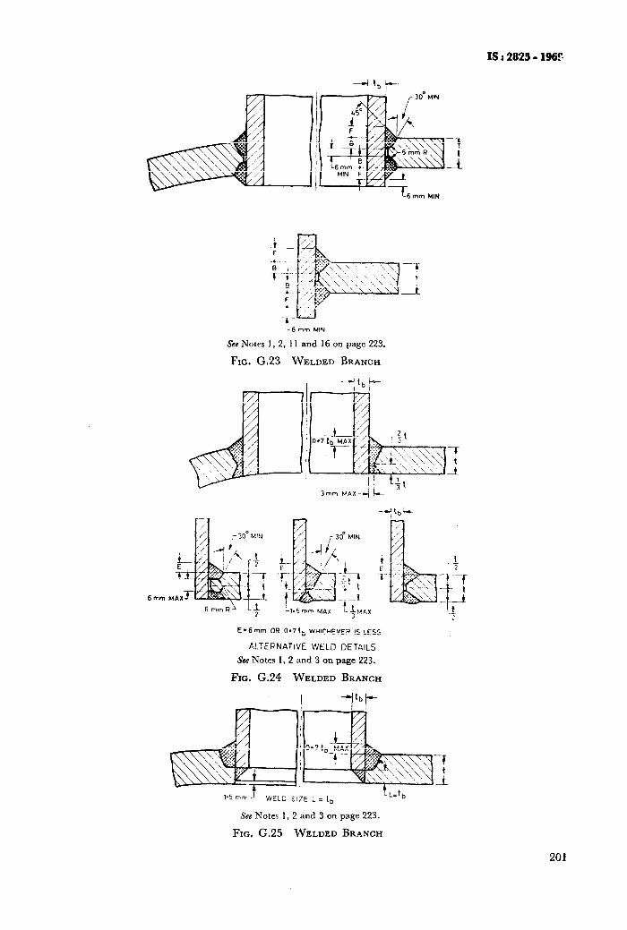
IS I 2825 - 1969
L6 mm MIN
See Notes 1, 2, 11 and 16 on page 223.
FIG. G.23 WELDED BRANCH
Er6mm OR 0'7tb WHICHEVER IS LESS
ALTERNATIVE WfLD DETAILS
See Notes 1,2 and 3 on page 223.
FIG. G.24 WELDED BRANCH
I --il'bP-
1.5 wm J WELD SIZE L = 1,
See Notes 1, 2 and 3 on page 223.
FIG. G.25 WELDED BRANCH
201
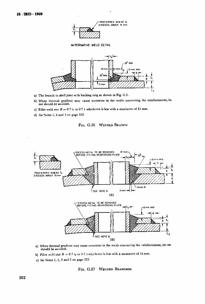
IS e 2025 - 1969
FERRED WHERE tr
+-
EOS ABOUT I5 mm
-7
AHERNATIVE WELD DETAIL
a) The branch to shell joint with backing ring as shown in Fig. G.3.
b) When thermal gradient may cause overstress in the welds connecting the reinforcement, its use should be avoided.
c) Fillet weld size B = 0.7 fr or 0.7 t whichever is less with a maximum of 15 mm.
d) &e Notes I,4 and 5 on page 223.
FIG. G.26 WELDED BRANCH
PREFERRED WHERE t, EXCEEDS ABOUT 15mm
METAL TO BE REMOVED FITTING REINFORCING PLATE
LSEE YOTE 6 3mm-4 k-
(A)
EXCESS METAL TO BE REMOVED BEFORE FITTING REINFORCING PLATE
--bi- r6mm MIN
LSEE NOTE 6
(8)
a) When thermal gradient may cause ovcrstress in the welds connecting the reinforcement, its use should be avoided.
b) Fillet weld size B = 0.7 tr or 0.7 t whichever is kss with a maximum of 15 mm.
c) See Notes 1, 2, 3 and 5 on page 223.
FIG. G.27 WELDED BRANCHES
202
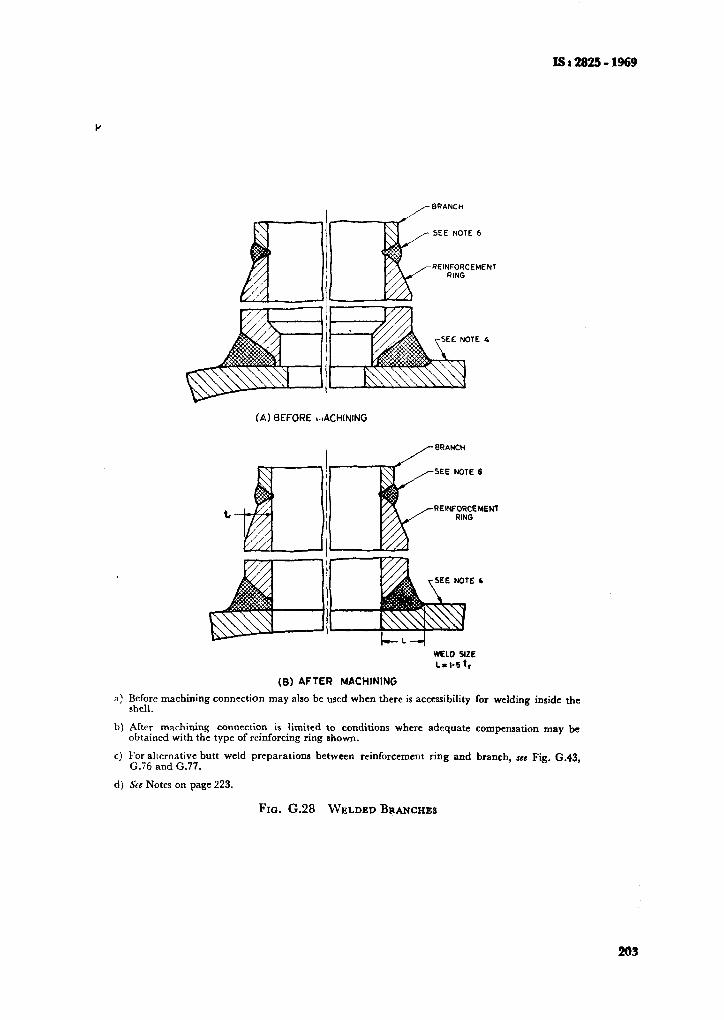
IS 8 2825 - 1969
I ,- BRANCH
-SEE NOTE 6
-REINFORCEMENT RING
(a) BEFORE MACHINING
RElNFORCEMENl
WELD SIZE
C-I.5 1,
(8) AFTER MACHINING
a) Before machining connection may also be used when there is accessibility for welding inside the shell.
b) After machining connection is limited to conditions where adequate compensation may be obtained with the type of r&forcing ring shown.
c) For alternative butt weld preparations between reinforcement ring and branch, see Fig. G.43, G.76 and G.77.
d) SEC Notes on page 223.
FIG. G.28 WELDED BRANCHES
203
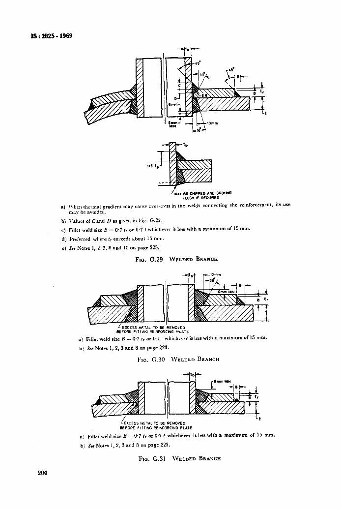
IS:2s25-1969
MA” BE CHIPPED AND GROW0 FLUSH IF REWREO
a) \t’hcn thermal gradient may cause ovcr:trrss in the welds connrcting the reinforcement, its USC
may be avoided.
bl Values of Cand D as given in Fig. G.22.
c) Flllct weld size B = O-7 I, or 0.7 t whichever is less with a maximum of 15 mm.
d) Preferred where tr exceeds hbout 15 mm.
e) See Notes 1, 2,3, 8 and 10 on page 223.
FIG. G.29 WELDED BRANCH
+bt f-‘o_m”
BEFORE FITTING REINFORCING PLATE
a) Fillet weld size E = 0.7 tr or 0.7 whichever is less with a maximum of 15 mm.
b) See Notes 1, 2,3 and 8 on page 223.
FIG. G.30 \~ELDEr~ BRANCH
‘EXCESS METAL TO BE REMOVED BEFORE FITTING REINFORCING PLATE
a) Fillet weld size B = 0.7 lr or 0.7 f whichever is less with a maximum of 15 mm.
bj SW Notrs 1, 2, 3 and 8 on page 223.
FIG. G.31 WELDED BRANCH
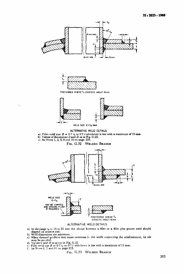
IS : 2825 - 1969
PREFERREO WHERE 1, EXCEEOS ABOUT 1Smm
WELD SIZE
ALTERNATIVE WELD DETAILS a) Fillet weld size E = O-7 I, or 0.7 f whichever is less with a maximum of 15 mm. b) Values ofdimensions Cand D as in Fig. G.22. c) Ses Notes 1, 2, 3, 8 and 10 on page 223.
Fm. G.32 WELDED BRANCH
MAY BE CHIPPED AND GROUND FLUSH
REFERRED WHERE 1,
EXCEEDS ABOUT 15mm
ALTERNATIVE WELD DETAILS
a) In the range lb = 14 to 20 mm the choice between a’fillet or a fillet plus groove weld should depend on relative cost.
b) Weld dimensions are minimum. c) When thermal gradient may cause overstress in the welds connecting the reinforcement, its USC
may be avoided. d) Values C and D as given in Fig. G.22. P) Filler w,-Id size B = 0.7 fr or 0.7 t whichever is less with a maximum of 15 mm. f) SH NX~tes 1, 2 and 11 on page 223.
FIG. G.33 ~YELDED BRANCH
205
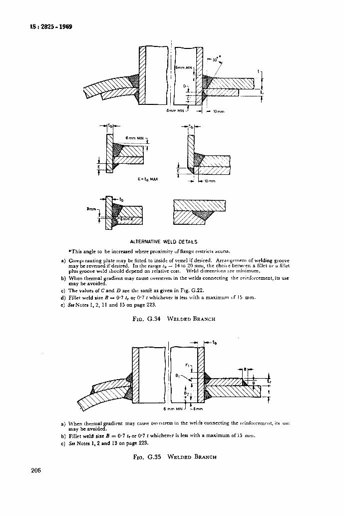
IS : 2825 - 1969
E’tb MAX
--Pi-
ALTERNATIVE WELD DETAILS
*This angle to be increased where proximity uf flange restricts access.
a) Compensating plate may be fitted to inside of vessel if desired. Arrarlgcmcnt of welding groove may be reversed if desired. In the range lb = 14 to 20 mm, the choice bctwc en a fillet or a fillet plus groove weld should depend on relative cost. Weld dimensions arc minimum.
b) When thermal gradient may cause overstress in the welds connecting the reinforcement, its USC may be avoided.
c) The values of C and D are the same as given in Fig. G.22. d) Fillet weld size B = 0.7 tr or 0’7 I whichever is less with a maximum uf 15 mm.
e) Sea Notes 1, 2, 11 and 15 on page 223.
FIG. G.34 WELDED BRANCH
a) When thermal gradient may cause overstress in the welds connecting the reinforcement, its use may be avoided.
b) Fillet wel& size B = O-7 tr or 0.7 t whichever is less with a maximum of 15 mm.
c) Ses Notes 1,2 and 13 on page 223.
Fro. G.35 WELDED BRANCH
206
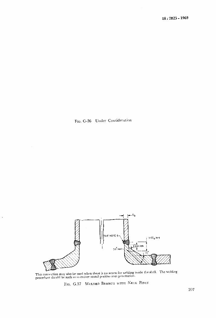
IS : 2825 - 1969
FIG. G-36 Under Consideration
ldt, MIN
.-_._,:.._ _^., .,l.,? ,,- ,,E_ rl w~,rn ihem is no acces for welding inside the shell. The welding
FIG. G.37 ~VELDED BRANCX ~VITII NECK PIECE
207
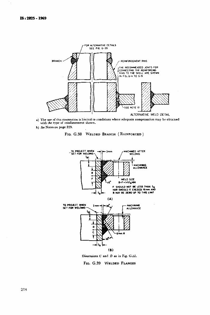
IS I 2825 - 1969
FOR ALTERNATIVE PETAILS
SEE FIG. G-39
BRANCH REINFOXEMENT RING
THE RECOMMENDED JOINTS FOR CONNECT!+& THE REINFORCING
ALTERNATIVE WELD DE TAIL
a) The use of this connection is limited to conditions where adequate compensation may be obtained with the type of reinforcement shown.
b) S#e Notes on page 223.
FIG. G.38 WELDED BRANCH ( REINFORCED )
F S”OULD NOT BE MSS THAN l,, NOR SHOULD 11 LllCEED llmm AWO
B MAY BE ZERO W 10 TMIS LIMIT
TO PROJEC: WHEN SET FOR WELDINQ -\
Dimensions C and D as iu Fig. G.22.
FIG. G.39 WELDED FLANGES
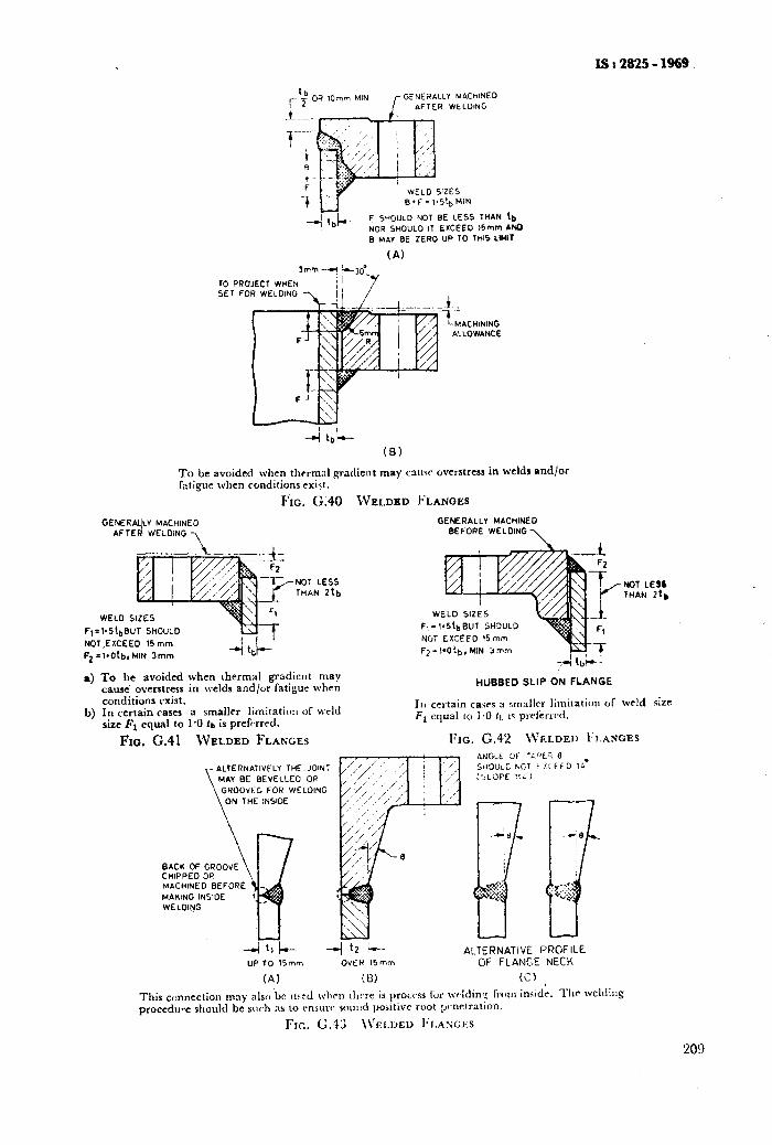
ISs2825-1969.
,- ‘+ OR 1Omm MIN l- GENERALLY MACHINED
AFTER wELOING
TG PRU SE1 FO
F SHOULD NOT BE LESS THAN tb NOR SHOULD IT EXCEED 14mm AND 8 MAY BE ZERO UP TO TtilS LMIT
(A)
.1._
f- MACHINING ALLOWANCE
(8)
To be avoided when thcrmzl gradient may cauw overstress in welds and/or fntigue when conditions c&t.
Fio. (2.40 WELDED FLANGES
GENERA~LV MACHINED AFTEd WELOiNG
NOT LESS THAN 2tb
NOT LE¶L THAN ztb
WELD SIZES
F,=l.S!&JT SHOULD
NOT.EXCEED 15 mm
F2 =lsOtb,MIN 3mm
a) To be avoided when thermal gradient may cause overstress in welds and/or fatigur when conditions exist.
b) In certain cases a smaller limltatiwl of weld size Fs equal to 1-O la is prefi rrrd.
HUBBED SLIP ON FLANGE
111 certain caws a sm:~llrr limilatiw of weld size F, equal LO i.0 II, is prrler1r.d.
_ FIG. (2.41 WELDED FLANGES
FLY THEN JOINT
EVELLED OR
FOR WELDING
BACK OF CHIPPED MACHINE0 BEFORE
MAKING INSIOE WELOING
-4 11 k- -_I 12 l-- ALTERNATIVE FROFILE UP TO 15mm OVER 15mm OF FLANGE NECK
(A) iD) (2) ,
This connection may also ‘be llrcd wlwn :hrre is procc’ss fur wcklinl: TIO~II imidr. Tllc’ weldit~g proccdu*.e should be slwh ;LS to unsure: wu~d positive root ynrtration.
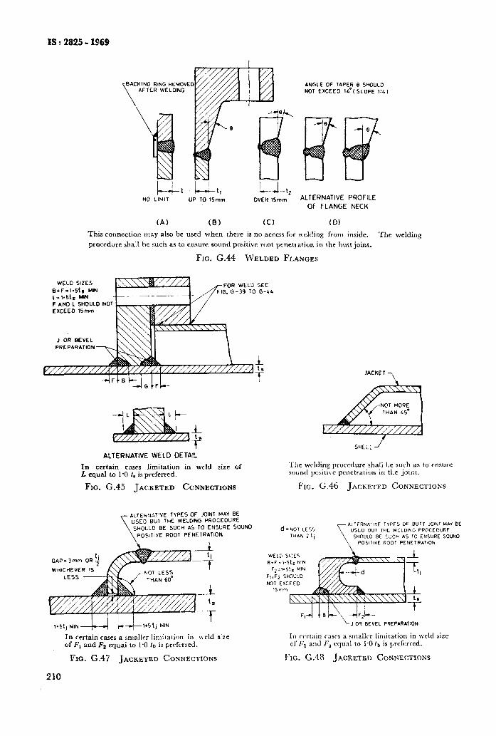
IS I 2825 - 1969
L-L, NO LIMIT UP TO 15mm OVER !5mm
(A) (8) CC) (D)
ANGLE OF TAPER 0 SHOULD NOT EXCEEO 14’C SLOPE 1:4)
ALTERNATIVE PROFILE OF FLANGE NECK
This connection may also be used when there is no access for tvelding from inside. The welding
procedure shall be such as to ensure sound positive root penetration in the butt joint.
FIG. G.44 WELDED FLANGES
WELD SIZES
B+F=b5t. MIN FOR WELD SEE G, G-39 TO G-44
L= 1~51. YIN F ANO L SHOULD NOT EXCEEO 15mm
J OR BEVEL
PREPARATION
1
1.
t’ ALTERNATIVE WELD DETA!L
In certain cases limitation in weld size of L equal to 1’0 ts is preferred.
FIG. G.45 JACKETED CONNECTIONS
ALTERNATIVE TYPES OF JOINT MAY BE “SE0 BUT THE WELDING PGOCEDURE
\ SHOULD BE SUCH AS TO ENSURE SOUNO
POSITIVE ROOT PENETRATION
1.51, M,N---Cr-_sl wl.51, MN
In certain cases a smalkr linlitation in weld S’ZC of F, and F2 equai to 1.0 fa is prcfcrred.
Fro. G.47 JACKETED CONNECTIONS
210
JACRET
7
SHELL J
‘Ik wcldipg procedure shall lie such as to ensure sound posltlve penetration in the joi::t.
FIG. G.46 JACKETED CONNECTIOKS
NOT EXCEED
BEVEL PREPARATION
In rcrtain tnscs a smaller limitation in weld aizc cl’ I;, and F, equal to I.0 tb is preferred.
FIG. G.48 JACKETED CONNECTIONS
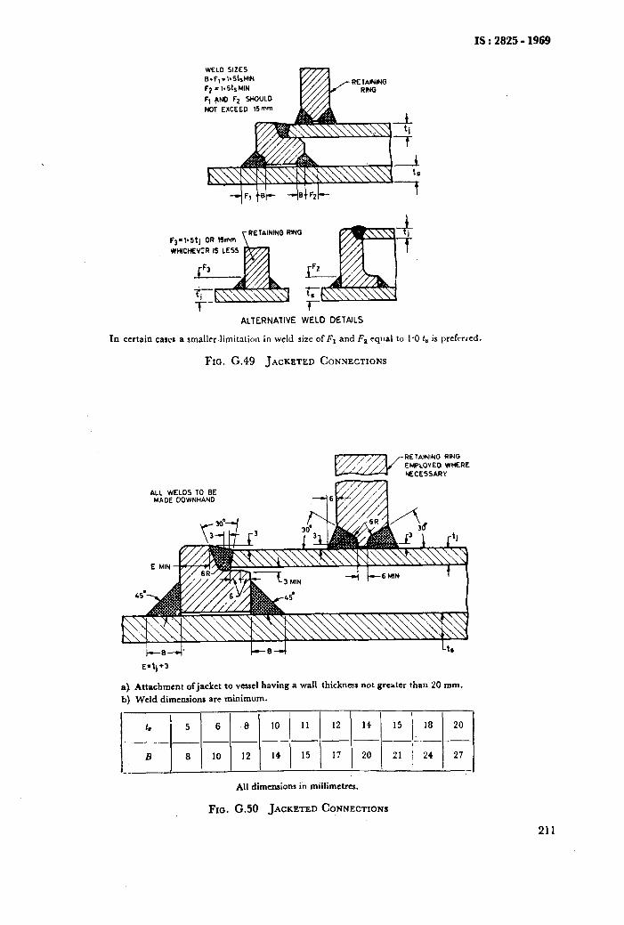
IS:2825-1969
WELD SIZES 8.F,.l.5t#4
Fp = 1.515 MIN
F, ANO F2 SHOULD NOT EXCEED l’imm
RETAINING RMG
ALTERNATIVE WELD DETAILS
In certain caws a smaller limitation in weld six of Fl and F2 equal to 1.0 f8 is prcftrrcd.
FIG. G.49 JACKETED CONNECTIONS
ALL WELDS TO BE MADE OOWNHAND
a) Attachment ofjackct to vessel having a wall thickness not greater than 20 mm.
b) Weld dimensions arc minimum.
All dimensions in miilimetrcs.
Fro. G.50 JACKETED CONNECTIONS
211
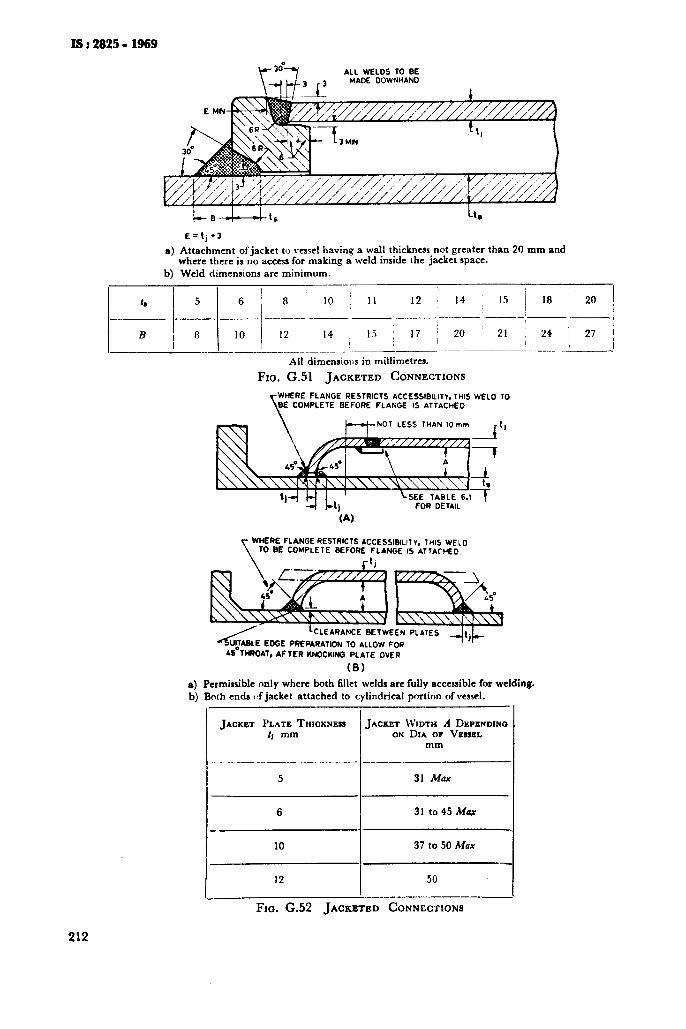
IS I 2825 - 1969
ALL WELDS TO BE WADE DOWNHAND
212
E=tj*3
a) Attachment of jacket to vessel having a wall thickness not greater than 20 mm and where there is no access for making a weld inside the jacket space.
b) Weld dimensions are minimum. --
I h 5 6 8 10 / 11 12 ; 14 ~ 15 18 20
__._~~ - ----- ___/-
J,
j
,_-..__‘p_I I
B I 8 14 1 I.? 10 12 I
j 17 : 20 21 ; 24 1 27 -I / _ _ __._. ___--
All dimensions in millimetres.
Fm. G.51 JACKETED CONNECTION
HERE FLANGE RESTRICTS ACCESSIBILITY, THIS WELD TO COMPLETE BEFORE FLANGE IS ATTACHED
(A)
WHERE FLPINGE RESTRICTS ACCESSIBILIT”, THIS WELD TO BE COMPLETE BEFORE FLANGE IS ATTACHED
~S’TMOAT. AFTER KNOCKING PLATE
(8)
a) Permissible only where both fillet welds are fully accessible for welding. b) Both ends c,f jacket attached to cylindrical portion of vessel.
JACKET PLATE THICKNESS JACKET WIDTH A D~PENDXNO tJ mm ON DIA OF VESSEL
mm
--
5 31 Max
I 6 I 31 to45 Mux
10 37 to 50 Max
I 12 !
50
FIG. G.52 JACKETED CONNECTIONS
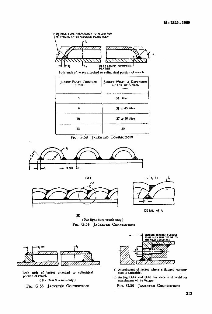
ISl28!2S=lB69
SUITABLE EDGE PREPARATION 10 ALLOW FOR 45-THROAT. AFTER KNOCKING PLATE OVER
-4 L’j tt, $Z;:;EtNCE BETWEEN J
Both ends of jacket attached to cylindrical portion of veuel.
JACKET PLATE THICKNESS
:j mm
5
6
10
12
_
-
-_
A.
-.
-
31 Max
31 to 45 Max
37 to 50 Max
50
Fxo. G.53 JACKETED CONNECTIONS
,
JACKET W~TX A DEPENDINO ON DIA OP VESSEL
mm
(A)
rA
DETAIL Al A
(8) ( For light duty vessels only )
FIG. G.54 JACKETED CONNECTIONB
WTANK KTWKN f LANK5 10 K SUCH THAT THE WIZLOI
Both ends of jacket attached to cylindrical portion of vessel.
( For class 3 vessela only )
Fm. G.55 JACKETED CONNECTIONS
a) Attachment of jacket where a flanged connec- tion is desirable.
b) See Fig. G.41 and f43 for detaiis of weld fir attachment of the angcs.
FIG. G.56 JACKETED CONNECTIONS
213
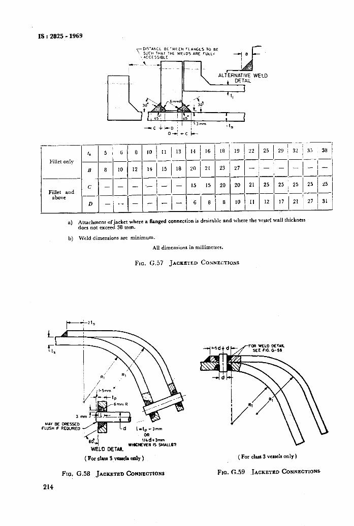
IS : 2825 - 1969
T- DISTANCE BETWEEN FLANGES TO BE SUCH THAI THE WELDS ARE FULLY
\ ACCESSIBLE --I”
Fillet and above
16 18
--
21 23
--
15 20
--
8 8
--
19
-
27 -
20
-
10
-
I I I -,-,-,-
21 / 25 1 25 / 25 --I-I-
ll 12 17 Cl I I I
_I_ I
-,_I
25 I
25
27 31 I
a) Attachment ofjacket where a flanged connection is desirable and where the VC@ wall thickness dots not exceed 38 mm.
b) Weld dimensions are minimum.
All dimensions in millimcfres.
FIG. CC.57 JACKETED COSNE~TIONS
MAY BE ORESKO FLUSH IF REOUlRED
WHICHEVER IS SMALLOT WELD DETAIL
( Pordw 3 vcncl8 only )
Fra. G.58 JACKETED CONNECTIONS
214
( For class 3 vessels only )
FIO. G.59 ,IACKETED CONNECTIONS
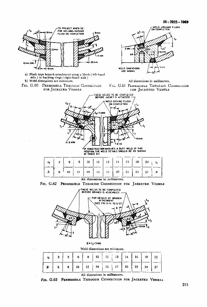
18:2825- 1969
0 PROJECT WHEN SE, OR WELMNG.GRCUNO LUS4i ON COMPLETIDN
a) Flush type branch attachmrnt using a block ( left-hand side ) or backing rings ( right-hand side )
b) Weld diniensions are minimum.
FIG. G.60 PERMISSIBLE THROUGH CONNECTION
FOR JACKETED VESSELS Ftc.
/ WELD GROUND FLUSH
ON COMPLETION
WELD OIMENSIONS iWi4
ARE MINIMA
Ail dimensions in millimctres.
G161 PERMISSIBLE THROUGH CONNECTION NOR JACKETED VESSELS
THESE WELDS TO BE COLPLETED BEFORE JACKET IS ATTACHED
OLIND FLUSH
*IVOLVES A BUTT WELD AT THIS POSITION THE WELD DETAILS SHOULD BE AS SHOWN IN TABLE 6.1
5 1 6 j 8 1 10 I’ I1 ( 13 ( 14 1 15 ( 18 1 20 / 1.
ti 4 10 i 12 1 14 1 15 1 17 ) 20 1 21 ) 23 1 27 1 B
All dimensions in millimctrcs.
FIG. G.62 PERMISSIBLE THROUGH CONNECTION FOR JACKETED VESSELS
THESE WELDS TO BE COMPLETED BEFORE BRANCH IS ASSEMBLED
E- ‘j’3MlN
Weld dimensions are minimum.
h 3 5 6 ( 8 / 10 / 11 / 13 14 16 18 22 1
- --- B 6 8 10 12 14 15 17 20 23 2’, j 1 j / 27
All dimensions in millimctrcr.
3x0. G.63 PERMKSSIBLE THROUGH CONNECTION FOR JACKETED VESSELS
215
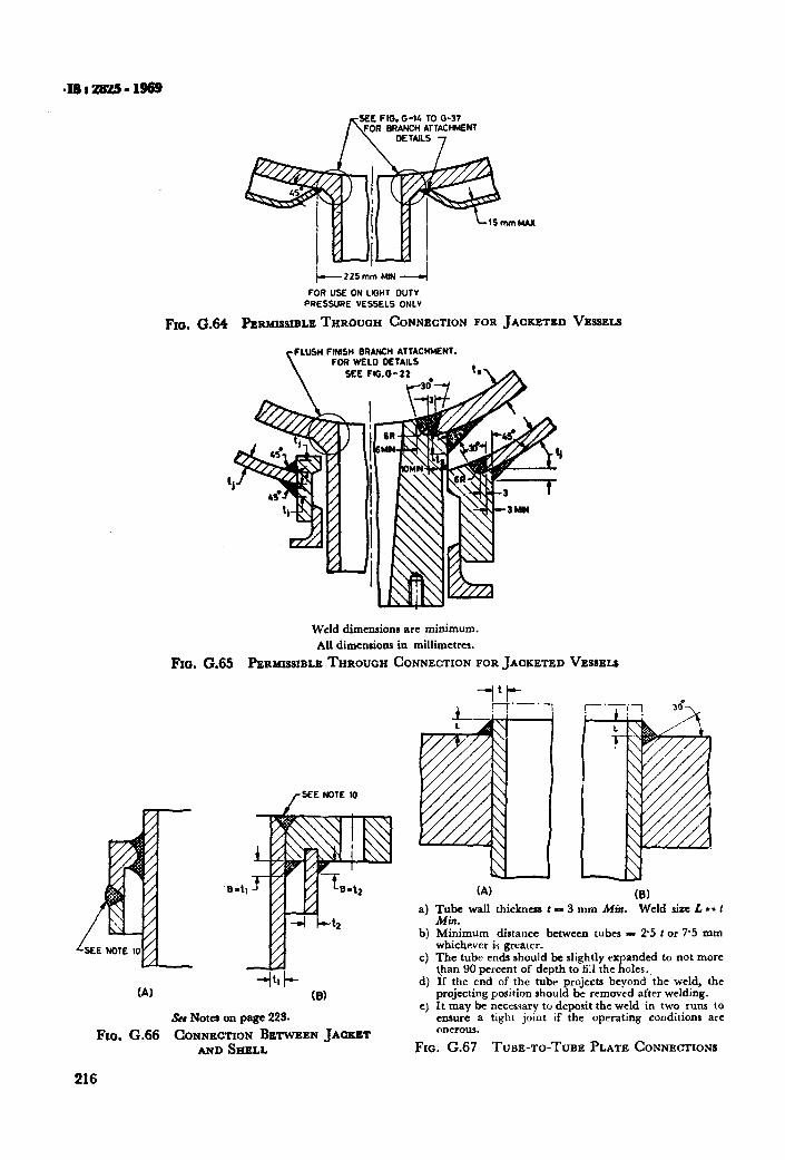
SEE FIG. G-14 TO G-37
h FOR BRANCH ATTACHMENT DETAILS ,
+225mm MN --./
FOR USE ON LIGHT DUTY
PRESSURE VESSELS ONLV
FIG. 0.64 PERMISSIBLE THROUQH CONNECTION FOR JACKETED VESSELS
FLUSH FIHSH BRANCH ATTACHMENT. FOR WELD DETAILS
Weld dimensions ax minimum. All dimensions in millimetres.
Fro. G.65 PERMISSIBLE THROUGH CONNECTION FOR JACKETED VESSELS
/SEE NOTE 10
(4 -+l t- (8)
&Notes on page 22%
FIO. G.66 CONNECTION BETWEEN JACKET AND SHELL
216
4
b)
4
4
e)
(A) (8) Tube wall thickness t - 3 mm Min. Weld size L l * I Min. Minimum distance between tubes - 25 t or 75 mm whichever is greater. The tube ends should be slightly expanded to not more {ban 90 percent of depth to fill the holes., If the end of the tube projects beyond the weld, the projecting position should be removed after welding. It may be necessary to deposit the weld in two runs to ensure a tight joint if the operating conditions are onerous.
Fro. G.67 TIME-TO-TUBE PLATE CONNECTIONS
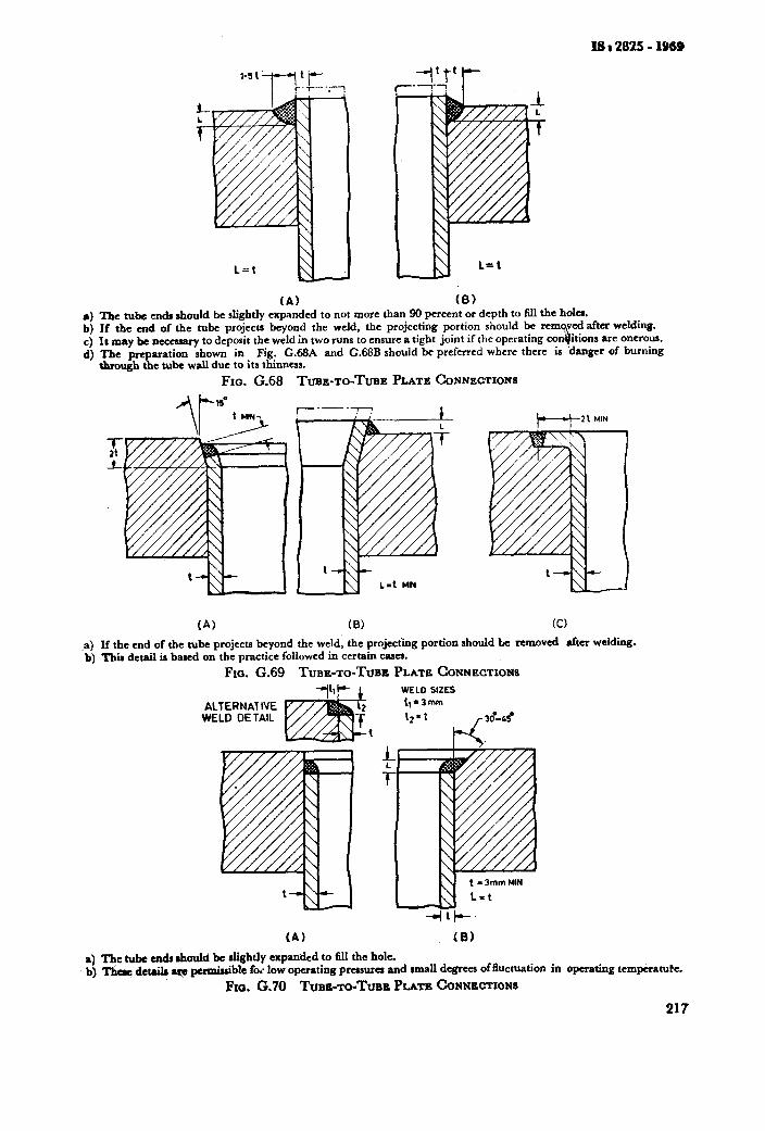
IS a 2025 - 1959
(A) (El S) The tube ends should be slightly expanded to not more than 90 percent or depth to till the hola. b) If the end of the tube projects beyond the weld, the projecting portion should be rem c) It may bc ncccssary to deposit the weld in two runs to ensure a tight joint if the operating arc onerous. d) The preparation shown in Fig. G.68A and G.68B should he preferred where there danger of burning
&rough the tuba wall due to its thinness.
Fra. G.68 TUBE-TO-TUBE PLATE CONNECTIOMI
IA) (0) (Cl
,a) If tbe end of the tube projects beyond the weld, the projecting portion should Le removed after welding. b) This detail is bared on the practice followed. in certain cases.
FIG. G.69 TUBE-TO-TUBE PLATE CONNECTIONS
+I- 1 WELD SIZES
ALTERNATIVE t1*3m
WELD DE TAIL 12’1
hY I I
(A) (8)
a) The t&a en& should be dightly expanded to fill the hole. b) Tl& detaih q permissible foi low operating prasurca and small degrees of fluctuation in operating temperatute.
Fxa. G.70 TUBB-TO-TUBI PLATE CONNECTIONS
217
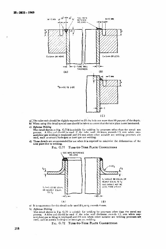
ls:2825-1969
t=Smm OR LESS
_cl I+-t=TuBE FALL
THICKNESS
(A) (6) I
t-- t MIN
l 0=1.5t TO 2.01
CC)
a);Thc tube ends should be slightly expanded to fill the hole not more than 90 percent of the depth. When using this detail special care should be taken to ensure that the tube plate is not laminated. b)
4 Rsfhtcr Welding
4
a?
b)
218
The detail shown in Fig. G.71B is suitable for wcldng by processes other than the metal arc process. A filler rod should be used if the tube wall thickness exceeds 1.5 mm when oxy- acetylene gas welding is employed and 2.0 mm when other suitable arc welding processes are used, such as atomic hydrogen or inert gas are welding.
Thae details are recommended for use when it is required to minimize the deformation of the tube plate due to welding.
FIG. G.71 TUBE-TO~TUBE PLATE CONNECTIONS
SEE NOTE REFERENCE WELDING
“1 r” T -T
t1 SHOULD BE EOUAL
OR NEARLY EOUAL
t, SHOULD BE EQUAL OR
NEARLY EOUAL TO 12
AND SHOULD NOT BE LESS THAN 2.5mm
-4t,!-- -41)_
(A) (8)
It is uncommor~ for this detail to be used if tr or 1s t xceeds 4 mm. Rcferc~~cc Welding The detail shown in Fig. G.70 is suilabL* for welding by procrsscs othrr than the metal arc process. A hllcr rod should be used if the tube wall thickness cxcerds l-5 mm when oxy- acetylene gas w, Idiug is employed and 2.0 mm when other suitable arc welding processes a=, tlsed, such as atomic hydrogrn or inert gas arc welding.
FIG. G.72 TUBE-TO-TUBE PLATE CONNECTIONS
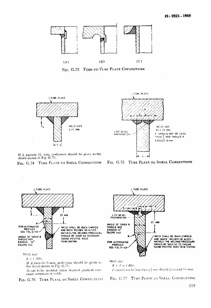
IS t 2825 - 1969
(A)
FIG. G.73 TUBE-TO-TUBE PLATE CONNECTSONS
If Z, exceeds 15 mm, ~~refcrence should br given to the detail shown in Fig. G.75.
FIG, G.74 TUBE PLATE TO SHELL CONNECTIONS FIG. G.75 TUBE PLATE TO SHELL CONNECTIONS
r TUBE PLATE
WELD SHALL BE BACK CtfIPPED AN0 BACK WELMO OR ALTER-
(SLOPE 1:L)
SOUND POSITIVE ROOT PENETRATION
If L rxcecds 15 mm, pref;rcilce sllould be si\ en to the detail shown in Fis. G.77. Its USC to be avoided when tllcrmzl gradient may cause overstt css in w&is.
FIG. G.76 TIJBE PLATE TO SHELL CONNEXXIOSS
J OH PREf
WELD SIZE
e*f=t MN
BE LESS
IOU10 IT
T TUBE PLATE
PREPARdTl0ti
ANGLE Of TAPER 0 ShWLO NOT
(SLOPE X4)
fCfi ALTERNATIVE
SEE f IG. G-43
EL0 SHALL BE GACK CHIPPED
BACK WELDED OR ALTER- ELV TN WELOING PROCEDVRE LO BE SUCH AS TO ENSURE
5olJNO POSITIVE ROOT PEKTRATIGN
Frc,. (;.77 TIME PI.ATE TO SHELL CONNECTIONS
219
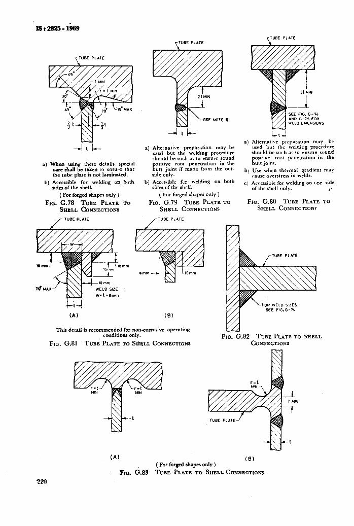
SEE FIG. G-71 AND G-75 FOR WELD DIMENSIONS
T TUBE PLATE
a) When using these details special care shall be taken to ensure that the tube plate is not laminated.
b) Accessible for v&ding on both sides of the shell.
( For forged shapes only )
Fxa. G.78 TUBE PLATE TO SHELL CONNECTIONS
/ TUBE PLATE
Omm
ylUBE PLATE
--I&-
a) Alternative preparation may be used but the welding procedure should be such as to ensure sound positive root penetration in the butt joint if made from the out- side only.
b) Accessible fcr welding on both sides of the shrlt.
( For forged shapes only )
FIG. G.79 TUBE PLATE TO SHELL CONNECTIONS
/TUBE PLATE
t-i-l (A) (8)
This detail is recommended for non-corrosive operating conditions only.
FIG. G.81 TUBE PLATE TO SHRLL CONNECTIONS
(A)
kt-l 4 Alternative preparation may bv
used but the wcldir:g procrrirlre should br such as to ensure sound positive root penetration in the butt joint.
bj Use when thermal gradient may cause overstress in wrlds.
c) Accessible for welding on one side of thr shell only. 4’
FIG. G.80 TUBE PLATE TO SHELL CONNECTION?
FOR WELD SIZES SEE FIG.G-74
FIG. G.82 TUBE PLATE TO SHELL CONNECTIONS
( For forged shapes only )
Fxo. c.83 TUBE PLATE TO SHELL CONNECTIONS
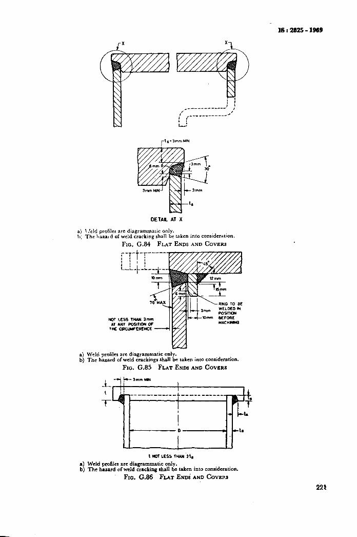
I6 : 2625 - 1969
DETAIL AT X
a) ! /eld profiles arc diagrammatic only. b) The hazard of weld cracking shall be taken into consideration.
Fro. G.84 FLAT ENDS AND COVERS
a) Weld profiles are diagrammatic only. b) The hazard of weld trackings shall be taken into consideration.
FIG. G.85 FLAT ENDS AND COVERS
-A-
-t
t NOT LESS InaN ‘It‘ a) Weld profilca are diagrammatic only. b) ‘The hazard of weld cracking shall be taken into conridcration.
Fxo. G.86 FLAT ENDS AND COVERS
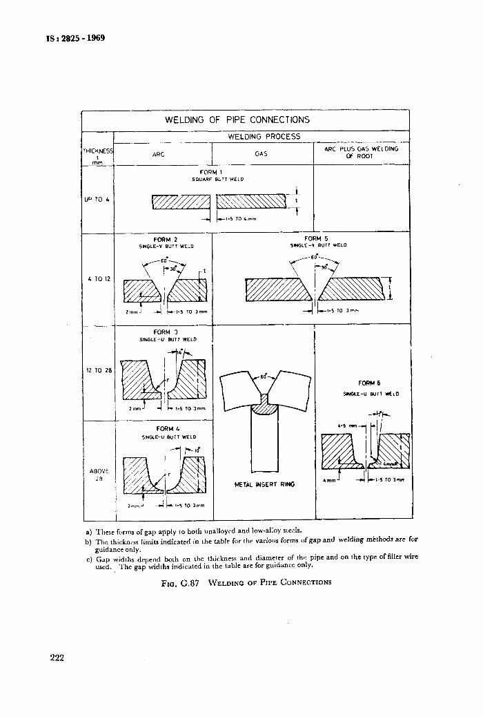
IS t 2825 - 1969
ICHNESS I
mm
WELDING OF PIPE CONNECTIONS
WELDING PROCESS
ARC GAS ARC PLUS GA5 WELDING
OF ROOT
F017M 1 SOUARE BUT1 WELD
; TO 12
FORM 3 S,&‘Gl.E -” WlT WELD
! TO 28
FOFiM6
YYGLE-U Bull WLLO
FORM 4 SINGLE-U BUTT WELD
ABOVE 28
METAL MERT RING
a) These fvrms of gap apply to both unalloyt-d and low-alloy steels.
b) The thickness limits indicated in the table for the various forms of gap and welding mtthods are for guidance only.
c) Gap widths depend both on the thickness and diameter of the pipe and on the type of filler wire used. The gap widths indicated in the table are for guidance only.
Fro. G.87 WELDING OF PIPE CONNECTIONS
222
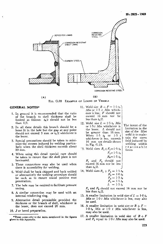
IS : 2625 - 1969
DEPOSITED LINING
CORROSION RESISTANT SHEE 1 LINING
CARBON STEEL
(A) FIG. G.88
GENERAL NOTES*
1.
2.
3.
4.
5.
6.
7.
8.
9.
10.
CORROSION RESISTING STEEL
(8)
EXAMPLE OF LINING OF VESSELS
11.
the ratio shall be
In general it is recommended that of the branch to shell thickness limited as follows: tt-,/t should not be less than l/5. 12.
In all these details this branch should be a loose fit in the hole but the gap at any point should not exceed 3 mm or tb/2 whichever is the lesser.
Special precautions should be taken to mini- mize the stresses induced by welding particu- larly when the shell thickness exceeds about 20 mm. ‘3.
When using this detail special care should be taken to ensure that the shell plate is not laminated.
These connections may also be used when there is accessibility for welding.
Weld shall be back chipped and back welded 14. or alternatively the welding procedure should be such as to ensure sound positive root penetration.
The hole may be omitted to facilitate pressure testing.
A similar connection may be used with an internal reinforcing ring. 15.
Alternative detail permissible provided the thickness or the branch of shell, whichever is the lesser, does not exceed 20 mm. 16.
J or bevel preparation. __
*These notes refer to the notes men-$oned in the figurer 17. A smaller limitation in weld size of B + F given in this Appendix. and Fl equal to 1 *O t Min may also be used.
Weld size B + F = 1.5 ft,) Min or 1.5 t M;n which- 1 ever is less; F should not 1 exceed 16 mm nor be 1 less than tb/2. I Weld size L = 1.5 fb Adin 1 or 1.5 t Min whichever is 1 Thc intent Of the the lesser. L should not 1 limitation in the
be greater than 16 mm. 1 uZe Of the fi11et When 1.5 tb or 1.5 t
i
weld is to main-
whichever is less, exceeds tain the stress
16 mm use details shown / ~~~~$“$~ in Fig. G.23.
Weld sizes B,+F,=1.5 tb reasonable limits
Fsc1.5 tb I
B,=1.5 tb I
Fl and F2 should not I exceed 16 mm nor be less I than tb/2. J Weld sizes B, + F, = 1.5 !b
B,= 1’0tb F2= 1’5tb F3 = 1.5 fb L = 1.5 tr
Fl and F., should not exceed 16 mm nor be less than fb/2.
A smaller limitation in weld size of 1, = 1-O tb Min or 1.0 t Min whichever is less, may also be used.
A smaller limitation in weld size or B + F = 1-O lb Min or 1.0 t Min whichever is less, may also be used.
223
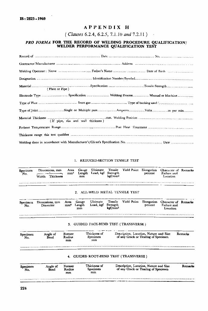
- IS : 2825 - 1969
APPENDIX H
( Clauses 6.2.4, 6.23, 7.1.10 and 7.2.11 )
PRO FORMA FOR THE RECORD OF WELDING PROCEDURE QUALIFICATION/ WELDER PERFORMANCE QUALIFICATION TEST
Record of ............................................................ Date .......................................... No. ........... ..................
Contractor/Manufacturer ............................................................ Address .................................... ..........
Welding Operator : Name .............................. Father’s Name .............................. Date of Birth ........................
D&gnation ................................................... Identification Number/Symbol ......................................................
Material ...................................................... Specifcation ................................ ( Plate or Pipe )
.Tensile Strength ........................
Electrode Type. ........................ Specification ..................... Welding Process.. ............. Manual or Machine ...............
T-e of Flux .................................... Inert gas ................................. Type of backing used :. ...............................
Type of Joint. ...................... Single .L or Multiple pass ................. .Amperes.. ............. Volts.. ............. . per min.. .......
Material Thickness ...................................................... mm. Welding Position ................................................... (If pipe, dia and wall thickness )
Preheat Temperature Range ................................................... Post Heat ‘Treatment ..........................................
T&kness range this test qualifies ..................................................................................................................
Weldirig done in accordance with Manufacturer’s/Client’s Specification No. ................................. Date .....................
1. REDUCED-SECTION TENSILE TEST
-~~ Specimen Dimensions, mm Area Gauge Ultimate Tensile Yield Point Eiongation Character of Remarks
No. T--~--7 mm* Length Load, kgf Strength percent Failure and Width Thickness mm kgf/mme Location
. . . . . . . . . . . . . . . . . . . . . . . . . . . . . . . . . . . . . . . . . . . . . . . . . . . . . . . . . . . . . . . . . . . . . . . . . . . . . . . . . . . . . . . . . . . . . . . . . . . . . . . . . . . . . . . . . . ~“.....‘..“.‘..“..‘...‘,................,....
2. ALL-WELD METAL TENSILE TEST
--_- ____________-___-_-__-_-~_ _____ Specimen Dimensions, mm Area Gauge Ultimate Tensile Yield Point Elongation Character of Remarks
No. Diameter mm’ Length Load, kgf Strength percent Failure and mm kgf/mm2 Location
. . . . . . . . . . . . . . . . . . . . . . . . . . . . . . . . . . . . . . . . . . .._........................I............................................................................................
3. GUIDED FACE-BEND TEST. (TRANSVERSE )
Former Radius
mm
--- ---___-_ Thickness of Description, Location, Nature and Size
Specimen of any Crack or Tearing of Specimen mm
Remarks
. . . . . . . . . . . . . . . . . . . . . . . . . . . . . . . . . . . . . . . . . . . . . . . . . . . . . . ..,..............................................................,..........................................
4. GUIDED ROOT-BEND TEST (TRANSVERSE )
An+dof ZZ
Thickness of Description, Location, Nature and Size Remsuks Specimen of any Crack or Tearing of Specimen
mm mm
. . . . . . . . ..‘......~............. .,............ . . . . . . . . . . . . . . . . . . . . . . . . . . . . . . . . . . . . . . . . . . . . . . . . . . . . . . . . . . . . . . . . . . . . . . . . . . . . . . . . . . . . . . . . . . . . . . . . . . . . . . . . . . . . . . . . . . . . . -w
224
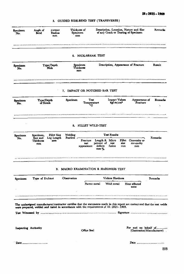
5. GUIDED SIDE-BEND TEST (TRANSVERSE)
FOI-KIU
RadiuI mm
Thickncas of Specimen
mm
Description, Location, Nature and, Size of any Crack or Tearing of Specimen
Remarks
. . . . . . . . . . . . . . . . . . . . . . . . . . . . . . . . . . . . . . . . . . . . . . . . . . . . . . . . . . . . . . . . . . . . . . . . . . . . . . . . . . . . . . . . . . . . . . . . . . . . . . . . . . . . . . . . . . . . . . . . . . . . . . . . . . . . . . . . . . . . . . . . . . . . . . . . . . . . . . . . . .
6. NICK-BREAK TEST
TyqcN!~~ s cimen 1 &cknaD Description, Appearance of Fracture Rault
_ ___ mm
. . . . . . . . . . . . . . . . . . . . . . . ..a................ . . . . . . . . . . . . . . . . . . ..a...*... . . . . . . . . . . . . . . . . . . . . . . . . . . . . . . . . . . . . . . . . . . . . . . . . . . . . . . . . . . . . . . . . . . . . . . . . . . . . . . . . . . . . . . . . . . . .
7. IMPACT OR NOTCHED BAR TEST
Sea .
Specimen Tat Impact Values RCrIUUb TemT_ kgf.m/cm* “F=: of
\
. . . . . . . . . . . . . . . . . . . . . . . . . . . . . . . . . . . . . . . . . . . . . . . . . . . . . . . . . . . . . . . . . . . . . . . . . . . . . . . . . . . . . . . . . . . . . . . . . . . . . . . . . . . . . . . . . . . . . . . . . . . . . . . . . . . . . . . . . . . . . . . . . . . . . . . . . . . . . . . . . .
8. FILLET W??LD-TEST
Tat Resultr
Fracture Length & Micro Fillet Convexity 2 Remarks
teat percent of tat size concavity appearance defects fusion mm mm
mm %
. ..n.........................................................................................................................................,...................
9. MACRO EXAMINATION & HARDNESS TEST
SpecimCn Type of Etchant Observation Vi&r3 Hardness Remarks I -- Parent metal Weid metal Heat a&ted
zone
._...................................... . . . . . . . . . . . . . . . . . . . . . . . . . . . . . . . . . . . . . . . . . . . . ..~....................................................................*......
The undenigncd man~acturcr/contractor cc&a that the statements made in this report are correct and that the tat wcl& were prepared, welded and tated in accordance with the requirements of IS : 2825 - 1969.
Test Witnarcd by ..*....................,......................................................... Signature .,.............................,...,...
Inspecting Authority
Date . . . . . . . . . . . . . . . . . . . . . . . . . . .
office sad For and on b&f of . . . . . . . . . . . .
(Contractor/ Manufacturer)
Date . . . . . . . . . . . . . . . . . . . . . . . . . . . . .
225
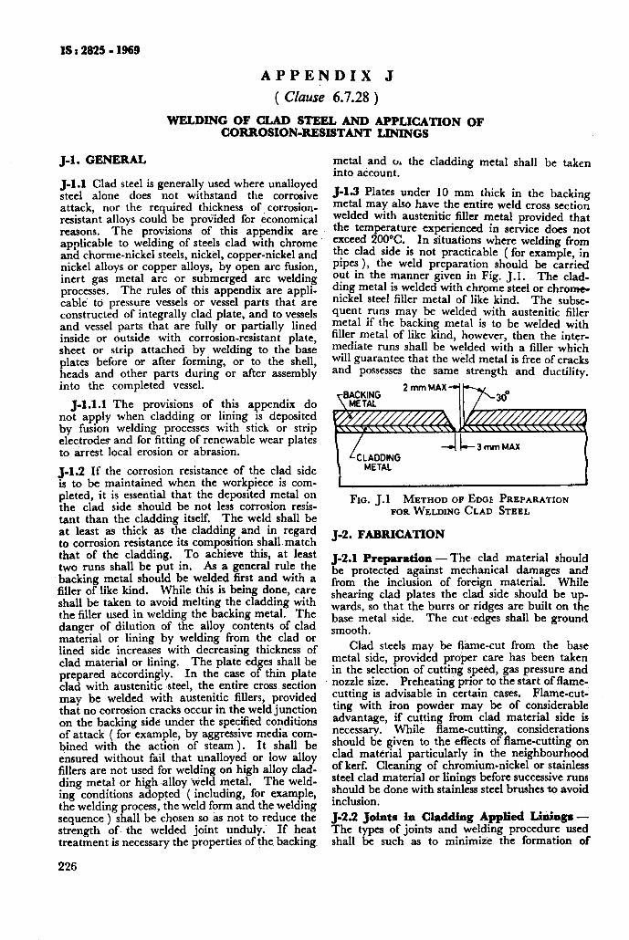
J-l. GENERAL
J-1.1 Clad steel is generally used where unalloyed steel alone does not withstand the corrosive attack, nor the required thickness of corrosion- resistant alloys could be provided for economical reasons. The provisions of this appendix are applicable to welding of steels clad with chrome and chorme-nickel steels, nickel, copper-nickel and nickel alloys or copper alloys, by open arc fusion, inert gas metal arc or submerged arc welding processes. The rules of this appendix are appli- cable to pressure vessels or vessel parts that are constructed of integrally clad plate, and to vessels and vessel parts that are fully or partially lined inside or outside with corrosion-resistant plate, sheet or strip attached by welding to the base plates before or after forming, or to the shell, heads and other parts during or after assembly into the completed vessel.
J-1.1.1 The provisions of this appendix do not apply when cladding or lining is deposited by fusion welding processes with stick or strip electrodes and for fitting of renewable wear plates to arrest local erosion or abrasion.
J-1.2 If the corrosion resistance of the clad side is to be maintained when the workpiece is com- pleted, it is essential that the deposited metal on the clad side should be not less corrosion resis- tant than the cladding itself. The weld shall be at least as thick as the .cladding and in regard to corrosion resistance its composrtion shallmatch that of the cladding. To achieve this, at least two runs shall be put in. As a general rule the backing metal should be welded first and with a filler of like kind. While this is being done, care shall be taken to avoid melting the cladding with the filler used in welding the backing metal. The danger of dilution of the alloy contents of clad material or lining by welding from the clad or lined side increases with decreasing thickness of clad material or lining. The plate ed es shall be prepared accordingly. In the case o P thin plate clad with austenitic .steel, the entire cross section may be welded with austenitic fillers, provided that no corrosion cracks occur in the weld junction on the backing side under the specified conditions of attack ( for example, by aggressive media com- bined with the action of steam ). It shall be ensured without fail that unalloyed or low alloy fillers are not used for welding on high alloy clad- ding metal or high-alloy icYeld metal. The weld- ing conditions adopted ( including, for example, the welding process, the weld form and the welding sequence ) shall be chosen so as not to reduce the strength of. the welded joint unduly. If heat treatment is necessary the properties of the backing,
226
IS : 2825 - 1969
APPENDIX J
( Clause 6.7.28 )
WELDING OF CLAD STEEL AND APPLICATION OF CORROSION-RESISTANT LININGS
metal and oA the cladding metal shall be taken into account.
J-l.3 Plates under 10 mm thick in the backing metal may also have the entire weld cross section welded with austenitic filler metal provided that the temperature experienced in service does not exceed 200°C. In situations where welding from the clad side is not practicable ( for example, in pipes ), the weld preparation should be carried out in the manner given in Fig. J.1. The clad- ding metal is welded with chrome steel or chrome- nickel steel filler metal of like kind. The subse- quent runs may be welded with austenitic filler metal if the backing metal is to be welded with filler metal of like kind, however, then the inter- mediate runs shall be welded with a filler which will guarantee that the weld metal is free of cracks and possesses the same strength and ductility.
-Ii-- 3 mm MAX
FIG. J.l METHOD OF EDGE PREPARATION FOR WELDING CLAD STEEL
J-2. FABRICATION
J-2.1 Preparation - The clad material should be protected against mechanical damages and from the inclusion of foreign material. While shearing clad plates the clad side should be up- wards, so that the burrs or ridges are built on the base metal side. The cut ‘edges shall be ground smooth.
Clad steels may be flame-cut from the base metal side, provided proper care has been taken in the selection of cutting speed, gas pressure and nozzle size. Preheating prior to the start of flame- cutting is advisable in certain cases. Flame-cut- ting with iron powder may be of considerable advantage, if cutting from clad material side is necessary. While flame-cutting, considerations should be given to the effects of flame-cutting on clad material particularly in the neighbourhood of kerf. Cleaning of chromium-nickel or stainless steel clad material or linings before successive runs should be done with stainless steel brushes to avoid inclusion. J-2.2 Joints in Cladding Applied Liihgr - The types of joints and welding procedure used shall be such as to minimize the formation of
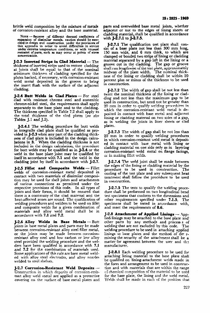
IS t 2925 - 1969
parts and overwelded base metal joints, whether adjacent or not to the edges of lining sheets or cladding material shall be qualified in accordance with J-2.7.1 to J-%7.5.
J-2.7.1 The ,qualiication test plate shall con- sist of a base plate not less than 300 mm long, 150 mm wide, and 6 mm thick, to which are clamped or bonded two strips of lining or cladding material separated by a gap left in the lining or a groove cut in the cladding. The gap or groove shall run lengthwise of the test plate, approximately midway of the plate width. The nominal thick- ness of the lining or cladding shall be within 20 percent plus or minus of the thickness to be used in construction.
J-2.7.2 The width of gap shall be not less than twice the nominal thickness of the lining or clad- ding and not less. than the maximum ga to be used in construction, but need not be great r than
t 20 mm in order to qualify welding procedu es in which the corrosion-resistant weld metal is de- posited in contact with base metal and adjacent lining or cladding material on two sides of a gap, as in welding the joints in liner sheets or clad plates.
J-2.7.3 The width of gap shall be not less than 20 mm in order to qualify welding procedures in whi.ch corrosion-resistant weld metal is deposit- ed in contact with base metal with lining or cladding material on one side only as in layering corrosion-resistant weld metal on flange facings, or in making fillet welds.
J-2.7.4 The weld joint shall be made between the edges of the lining or cladding material by the procedure to be used in construction. The cooling of the test plate and any subsequent htat treatment shall follow the procedure to be used in construction.
J-2.7.5 The tests to qualify the welding proce- dure shall be performed on two longitudinal bend test specimens that conform to the dimensions and other requirements specified under 7.1.5. The specimens shall be tested in accordance with, and meet the requirements of 8.6.
J-2.8 Attachment of Applied Linings - .\pp- lied linings may be attached to the base plate and. other parts by any methods and process, s of welding that are not excluded by this code. The welding procedure to be used in attaching applied linings to base plates and the method of det ‘r- mining the security of the attachment shall be a matter for agreement between the user and th: manufacturer.
J-2.8.1 Each welding procedure to be used for attaching lining material to the base plate shall be qualified on lining-attachment welds made in the form and arrangement to be used in construc- tion and with materials that are within the range r,f chemical composition of the material to be used for the base plate, the lining and the weld metal. \Velds shall be made in each of the position that
227
brittle weld composition by the mixture of metals of corrosion-resistant alloy and, the base material.
NOTE -&cause *of different thermal coefficients of exparuion of dirimllar met& caution’ should be exer- tired in desi.? and construction under the provisions of this appendix in order to avoid difficulties in service under extreme temperature conditions, or with unusual restraint of par& such as may occur at points of stress concentration.
J-2.3 Inserted Strips in Clad Material - The thickness of inserted strips used to restore cladding at joints shall be equal to that of. the nominal minimum thickness of cladding specified for the plates backed, if necessary, with corrosion-resistant weld metal deposited in the groove to bring the insert flush with the surface of the adjacent cladding.
J-2.4 Butt Welds in Clad Plates - For steel clad with resistant chrome steel and austenitic chrome-nickel steel, the requirements shall apply separately to the base plate and to the cladding. The thickness specified in Table 7.2 shall apply to the total thickness of the clad plates (see also Tables J.1 and 5.2).
J-2.4.1 The welding procedure for butt welds in integrally clad plate shall be qualified as pro- vided in J-2.3 when any part of the cladding thick- ness of clad plate is included in the design calcu- lations in 3. When the cladding thickness is not included in the design calculation, the procedure for butt welds may be qualified as in J-2.4 or the weld in the base plate joint may be qualified by itself in accordance with 7.1 and the weld in the cladding joint by itself in accordance with J-2.7.
J-2.5 Fillet and Composite Welds - Fillet welds of corrosion-resistant metal deposited in contact with two materials of dissimilar composi- tion may be used for shell joints and attachments of various connections 2s permitted under the respective provisions of this code. In all types of joints and their forms, it should be ensured that there is a continuity of the clad material and the heat-affected zones are sound. The qualification of welding procedures and welders to be used on fillet and composite welds for a given combination of materials and alloy weld metal shall be in accordance with 7.1 and 7.2.
J-2.6 Alloy Welds in Base Metals -Butt joints in base metal plates and parts may be made between corrosion-resistant alloy steel filler metal, or the joints may be made between corrosion- resistant alloy steel and low carbon or low alloy steel provided the welding procedure and the wel- ders have been qualified in accordance with 7.1 and 7.2 for the combination of materials used. Some applications of this rule are base metal weld- ed with alloy steel electrodes, and alloy nozzles welded to steel shelves.
J-2.7 Corrosion-Resistant Weld Deposits d Construction in which deposits of corrosion-resis- tant alloy weld metal are applied as 2 protective covering on the surface of base metal plates and
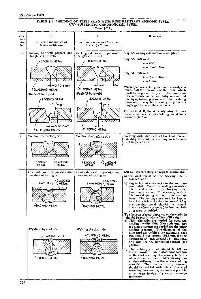
IS : 2825 - 1969
TABLE J.l WELDING OF STEEL CLAD WITH RUST-RESISTANT CHROME STEEL AND AUSTENITIC CHROE-NICKEL STEEL
( Clause J-2.4 )
OPE RA-
TIOI NO
228
A B REMARKS
FOR ALLTHICKNESSESOP FOR THICKNESSES 08 CLADDING CLADDING MLTAL METAL > 2’5 Illll’l
3aeking side weld preparation: Single-V butt weld
Backing side weld preparation: Single-V butt weld
jingle-V or single-u butt weld at option:
/BACKING METAL /
BACKING METAL jingle-V butt weld
a = 60’ b=2mmMax
L OTO8mm
CLADDING METAL
;ing!e-U butt weld
,- BACKING METAL
Velding the backing side Welding the backing side
&ACKlNG kLADDlNG METAL METAL
Iad side weld preparation and welding of sealing run
CLADDING lmm MINI \METAL
Wrlding the clad side Welding the clad side
y CLADDING METAL
I BACKING METAL LBACKING METAL
kLADDlNG METAL
Single-U butt weld
/-BACKING METAL
1 CLADDING METAL
Clad side weld preparation and welding of sealing run
CL ADDING 1 mm MiNl[ METAL
hCKlNG METAL
LADDING METAL
jingle-U butt weld
b=2mmMax r=4mm
When open arc welding by band is wed, c ia made half the thickness of the metal which must bc deposited to put in the first run. For semi-mechanical and fully mechanized inert-gas, submerged-arc and other welding processes, it may bc ncecssary to provide a larger gap between the root facca.
For method B, the sides adjoining the root face must be clear of cladding metal for a distance > 2 mm.
Welding with filler metal of like kind. When welding the root, the cladding metal should not be penetrated.
.--.-- ..-_ - -____d
3ut out the root deep enough to ensure that: a) the weld metal on the backing side is
reached, and
b) slag inclusions and cracks in the root arc eliminated. Weld the sealing run with a filler metal suited to the backing metal ( see diagram ) or, if necessary, with a filler metal giving a tough intermediate layer. The scaling run should be kept at least 1 mm below the cladding metal. After the backing metal should be ground smooth ( where necessary ) before the clad- ding metal is welded.
The first run of metal deposited on the c&d aide should be put in with a filler of like kind.
a) Thin electrodes are needed for open arc welding, whilst thin Miller rods and not too high a current are needed for the other welding processes. The diameter of the filler used for welding the austenitic root run should not exceed 3.15 mm for the downhand (F) and vertical ( V) positions, or 4 mm for the horizontal-vertical (H) position.
b) The welding current should be kept as low as possible. The bottommost root fun on the clad side may, if necessary, be weld- ed with an austcnitic filler having an analysis differing from that of the cladding- material. The subsequent runs, however, should bc welded with tillera of a kind matching the claddhng as closely as possible, or at least having the same corroaioe resistance.
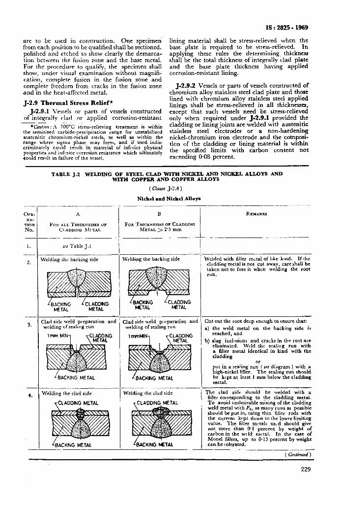
are to be used in construction. One specimen from each position to be qualified shall be sectioned. polished and etched to show clearly the demarca- tion between the fusion zone and the base metal. For the procedure to qualify, the specimen shall show, under visual examination without magnifi- cation, complete fusion in the fusion zone and complete freedom from cracks in the fusion zone and in the heat-affected metal.
J-2.9 Thermal Stress Relief*
J-2.9.1 Vessels or parts of vessels constructed of integrally clad or applied corrosion-resistant
l Caution : A 7OO’C stress-relieving treatment is within the sensitized carbide-precipitation range for unstabilized austenitic chromium-nickel steels, as well as within the range where sigma phase may form, and if used indis- criminately could result in material of inferior physical properties and inferior corrosion resistance which ultimately Could result in failure of the vessel,
IS : 2825 - 1969
lining material shall be stress-relieved when the base plate is required to be stress-relieved. In applying these rules the determining thickness shall be the total thickness of integrally clad plate and the base plate thickness having applied corrosion-resistant lining.
J-2.9.2 Vessels or parts of vessels constructed of chromium alloy stainless steel clad plate and those lined with chromium alloy stainless steel applied linings shall be stress-relieved in all thicknesses, except that such vessels need be stress-relieved only when required under J-2.9.1 provided the cladding or lining joints are welded with austenitic stainless steel electrodes or a non-hardening nickel-chromium iron electrode and the coinposi- tion of the cladding or lining material is within the specified limits with carbon content not exceeding 0.08 percent.
OPE- RA-
TION No.
1.
2.
m
3.
-
4.
_-
-;_
-
- 7
--
,
TABLE J.2 WELDING OF STEEL CLAD WITH NICKEL AND NICKEL ALLOYS AND WITH COPPER AND COPPER ALLOYS
( Clause J-2.4 )
Nickel and Nickel Allop
A
FOR ALL THICKNUSES OF CLADDING MJTAL
JEW Table J. 1
Welding the backing side
L BACKING METAL
Clad side weld preparation and welding of sealing run
iBACKlNG METAL
Welding the clad side
yCLADDlNG METAL
rBACKING METAL
-
-
.-
-.... ,
_-
B
FOR THICKNESSES OF CLADDING METAL > 2.5 mm
Welding the backing side
Clad side weld pt-eparation and welding of sealing run
LBACKING METAL
Welding the clad side
r CLADDING METAL
&ACKlNG METAL -__- ___
-
-
_-
REMARKS
Welded with filler metal of like kind. If the cladding metal is not cut away, care shall be taken not to fuse it when welding the root run.
Cut out the root deep encugh to ensure that
4
b)
the weld metal on the backing side is reached, and slag inclusions and cracks in the root are eliminated. Weld the sealing run with a filler metal identical in kind with the cladding
put in a sealing runo’( see diagram ) with a high-nickel filler. The sealing run should be kept at least 1 mm below the cladding metal.
The clad side should be welded with a filler corresponding to the cladding metal. To avoid undesirable mixing of the cladding weld metal with Fe, as many runs as possible should be put in, using thin filler rods with the current kept down to the lower limiting value. The filler metals usld should give not more than 0.1 percent by weight of carbon in the weld metal. In the case of Monel fillers, up to 0.15 percent by weight can be tolerated.
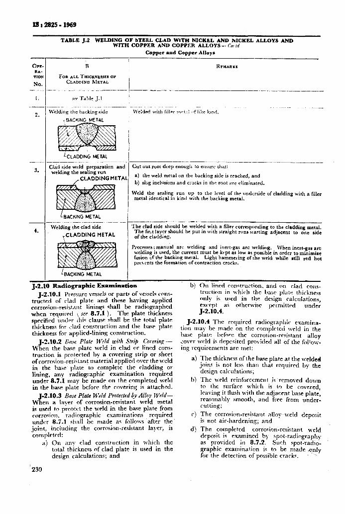
IS a 2825 - 1969
TABLE J.2 WELDING OF STEEL CLAD WITH NICKEL AND NICKEL ALLOYS AND WITH COPPER AND COPPER ALLOYS -- f?o:ot.:,i
Copper and Copper Alloys
I3 / RPMARKI ,
FOR ALL ~~~~~~~~~~~~ OY CLADDIXO bfETAL
! --__.^__.___._____I- ----- :_P--.- -._--___-_ ,__._.-_.. -_-________
OPR RA-
1101
No. -_-. -_
I.
7--
2.
3.
4.
Weldmg the hacking side
&ADDING METAL
Chd side weld preparation and welding the scaling run
/CLADDING METAL
L BACKING METAL __.__ _.._.._-.. ._ -__-_ --- --
Welding the clad side
&LADDING METAL
iBACKlNG METAL
‘-
J-2.10 Radiographic Examinat ia
Cut out root deep enough to cnsurc that:
a) tht weld metal cbn the backing side is reached, and
b) slzg inclusions and cocks in the root are eliminated.
Weld the sealing run up to the level of the underside of cladding with a filler metal identical in kind with the backing metal.
---- --.- .-_-.-__ T’he clad side should be welded with a filler corresponding to the cladding metal. The f&t layer should be put in with straight runs starting adjacent to one side of the cladding.
Procrsscs : manual arc welding and inert-gas arc welding. When inert-gas arc welding is used, the current must be kept as low ac possible in order to minimize fusion of the backing metal. Light hammeting of the weld while rdll red hot prctrnts the formation of contraction cracks.
j-2.10.1 v r6-vu-e vessels or parti of vessels cons- . tructed of rlad plate and those havine; applied rorrosion-resistitnt linings shall be radlographed when rquirpd ( SCF 8.7.1 ). The plate thickness specified under this clause shall be the t.otal plate thicknes< for clad construction and the basr plate thickness for applied-lining construct.ion.
J-2.10.2 Rinse Plate Weld with S!rifi Cooeriqc .- When the base plate weld in clad or lined cons- truction is protected by a cnvering strip or sheet ofcorrosiorl-resiitarlt matarial applied over the weld in the base plate to complete the cladding 01 lining, any radiographic examination required under 8.7.1 may be made on the completed w&~ in the base plate before the coverir.q is attached.
J-2.10.3 Bose Plate Weld Protected 4v A&y WAd- Whm a Iaver of corrosion-resistant weld metal is used to prot&t the weld in the base plate from corrosion. radiographic esaminations required 1mdf.r 8.5.1 shall bc made ac fbllows after the joint, including the corrosion-resistant layer, is complfwl:
a) On any clad construction in which the total thickness nf clad plate is used in the design calculations; and
230
bj On lined conqtruction. and on clad cons- tructic-*n in which the base plate thickness only is used in the design calculations, exe-tpt a5 otherwise prrmitted under J-2.10.4.
J-2.10.4 The required radiographic examina- tion may he made on the romplcted weld in the base plate before the corrosion-rrsistant alloy Lover weld is depcsited provided all of the follolv- ing requirements arc met:
The thickness of the base plate at the welded joint is not less than that required by the design calculations; The weld rcinf~.~rccmeat ix removed dolvn to the surface which is to be covered, IFaving it flush wit.h the adjacent base plate, reasonably smooth, and free from under- rutting; The corrosion-resistant allo~~~eld deposit is not air-hardening; and The completed corrosion-resistant weld dcpoyit is examined b)- spot-radiography as provided in 8.7.2. Such spot-radio- graphic examination is to be made .only for the detection of possible crack?. ’
ISr282!i-1969
‘by welding. Repetition of the radiography, the heat treatment, or the hydrostatic test of the vesse! after lining repairs is not required except when there is reason to suspect that the repair welds may have defects that penetrate into the base plate, in whir.+case the inspector shall decide which one or more shall be repeated.
5-2.11.3 When the .test fluid seeps behind the applied liner, there is danger that the fluid will remain in place u;. il the vessel is put in service. In cases where the operating temperature of the vessel is above the boiling point of the test fluid, the vessel should be heated slow1 for a sufficient time to drive out all test fluid rom behind the fy applied liner without damage to tl e liner. This heating operation may be performed at the vessel marmfacturing plant or at the plant where the vessel is being installed. After the test fluid is driven out, the lining should be repaired by welding.
J-2.11 Tightness of AppIied Lining
J-2.11 .l A test for tightness of the applied lining that will be appropriate for the intended service is recommended, but the details of the test shall be a matter for agreement between the user and the manufacturer. The test should be such as to assure freedom from damage to the load-carrying base plate. When rapid corrosion of the base plate is to be expected from contact with the contents of the vessels, particular care should be taken in devising and executing the tightness test.
J-2.11.2 Following the hydrostatic pressure test, the interior of the vessel shall be inspected to de- termine if there is any seepage of the test fluid through the lining. Seepage of the test fluid behind the applied lining may cause serious damage to
liner when the vessel is put in service. When occurs precautions as laid down in J-2.11.3
shall be followed and the lining shall be repaired
APPENDIX K
[ Clauses 7.2.4.1 (B)(b)(2), 7.2.6.3(b) and 8.5.11 ]
METHOD OF PREPARING ETCHED SPECIMEN
K-l. GENERAL K-l.1 The surfaces to be etched should be smoothed by filing or machining or by grinding on metallographic papers. With different alloys and tempers, the etching period will vary from a few seconds to several minutes and should be continued until the desired contrast is obtained. As a protection from the fumes, liberated during the etching process, this work should be done under a hood. After etching, the specimens should be thoroughly rinsed and then dried with a blast of warm air. Coating the surface with a thin clear lacquer will preserve the appearance.
K-2. ETCHANTS FOR FERROUS MATERIALS
K-2.1 Etching solutions suitable for carbon and low-alloy steels, together with directions for their use, are suggested as follows:
a) Hydrochloric Acid - Hydrochloric acid and water equal parts by volume. The solution should be kept at or near the boil- ing temperature during the etching pro- cess. The specimens are to be immersed in the solution for a sufficient period of time to reveal all lack of soundness that might exist at their cross-sectional surfaces.
b) Ammonium Persulphate- One part of am- monium persulphate to nine parts of water
4
4
by weight. The solution should be used at room temperature and should be applied by vigorously rubbing the surface to be etched with a piece of cotton saturated with the solution. The etching process should be continued until there is a clear defini- tion of the structure in the weld.
Iodine and Potassium Iodide - One part of powdered iodine, two parts of powdered potassium iodide, and ten parts of water, all by weight. The solution should be used at room temperature and brushed on the surface to be etched until there is a clear definition or outline of the weld.
.Nitric Acid - One part of nitric acid and three parts of water by volume. ( Cuution : 4lways pour the acid into the ‘water. Nitric acid causes bad stains and severe burns. ) The solution may be used at room temperature and applied to the surface to be etched with a glass stirring rod. The specimens may also be placed in a boiling solution of the acid but the work should be done in a well-ventilated room. The etching process should be continued for a sufficient period of time to reveal all lack of soundness that might exist at the cross-sectional surfaces of the weld.
231
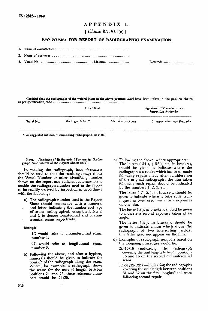
ISr2825-1969
APPENDIX L
[ Clause 8.7.10.1 (e) ]
PRO FORMA FOR REPORT OF RADIOGRAPHIC EXAMINATION
1. Nameofmanufacturcr ..................................................................
2. Name of customer ........................................................................
3. VCWI No, ................................................ Material ..................... Electrode . . . . . . . . . . . . . . . . . . . . . . . . . . .
Certified that the radiographs of the welded joints in the above pressure vcascl have been taken in the position shown aa per spccilicationjcode . . . . . . . . . . . . . . . . . . . . . . . . . . . . . . . . . . . . . . . . . . . . . . . . ~. . . . . . . . . . . . . .
Office Seal Ggnaturc of Manufacturer’s Inspecting Authority
Serial No. Radiograph No.* Material thickness Intcrprcta!ion and Remarks
*For suggested method of numbering radiographs, see Note.
NOTE - Numbering of Radiographs ( For use in ‘Radio- graph No.’ column of the Report Sheets only).
In making the radiograph, lead characters should be used so that the resulting image shows the Vessel Number or other identifying number shown on the report and sufficient information to enable the radiograph number used in the report to be readily derived by inspection in accordance with the following:
a) The radiograph number used in the Report Sheet should commence with a numeral and letter indicating the number and type of seam radiographed, using the letters L and C to denote longitudinal and circum- ferential seams respectively.
Example :
J4
232
1C would refer to circumferential seam, number 1.
2L would refer to longitudinal seam, number 2.
Following the above, and after a hyphen, numerals should be given to indicate the positio> of the radiograph along the seam. Where, for example, a radiograph shows the seams for the unit of length between positions 24 and 25, these reference num- bers would be 24125.
C)
4
Following the above, where appropriate: The letters ( RI j, ( R2 ), etc, in brackets, should be given to indicate where the radiograph is a retake which has been made following repairs made after consideration of the original radiograph: the film taken following each repair should be indicated by the numbers 1, 2, 3, etc.
The letter ( IT. S. ), in brackets, should be given to indicate where a tube shift tech- nique has been used, with two exposures on one film.
The letter ( S ), in brackets, should be given to indicate a second exposure taken at an angle.
The letter ( X), in brackets, should be given to indicate a film which shows the radiograph of two intersecting welds : this letter need not appear on the film.
Examples of radiograph numbers based on the foregoing procedure would be:
2615/16_indicating the radiograph covering the unit length between positions 15 and 16 on the second circumferential seam.
lL-31/32(R2)- indicating the radiographs covering the unit length between positions 31 and 32 on the first longitudinal seam following second repair.

IS:28259i&B
AP,PENDIX M
( Clause 8.3.1.1 )
PRO FORMA FOR MAKER’S CERTIFICATE OF MANUFACTURE AND PRODUCTION TEST
I. MANUFACTURE
Manufacturer’s name and address .....................................................................................................................
Purchaser’s name and address .................................... ...................................................... Name ofthe purchaser
Inspecting authority & addrar ...........................
Type ofvessel (horizontal ........................... Vessel No. (Manufacturer’s.. ......................... Year built .................. or vertical ) Serial No. )
No.ofshells8~drum.s.. .......... ................... Dia(insideoroutside). .................... Overall length or height of vaseI..
Identification marks or stamps ................................................... DrawingNo. ...................................................
Brief description of vessel ( Intended use or application, duty, etc ) ........................................................................
Working pressure ........................... Design pressure.. ...................... HHdrauhc teatprarure ydraubc test
.....................................................................
Witnessed by .......................................
Working temperature ......................................................... Design temperature ................................................
Joint efficiency factor : Long seam. ............................................ Girthorcircumferentialseam ..............................
Shell plates ( Thickness ). Girth or circumferential ......... ................ T(%: o~;m~ongitudinal.. .........................
0. .......................................... ( No. 8c Type). .................
Materials of construction ( material specification ) ................................................................................................
Tensile strength .......................................... Elongation ........................ Chemical composition, if any.. ................
Heat treatment ( preheat, ..................................................................... Details of heat treatment .................. stress relief or ................. Preheat temperature ..................... if any (to be attached as .................. normalizing ) ..................... an enclosure ) ..................
Whether steel maker’s certificate of manufacture & results of test attached ..................................................................
Details of shop inspection ( Report of ................................. Calibration and dimensional ....................................... manufacturer’s inspecting authority ) .............................. Check on vessel .......................................
Details of repairs carried out, if any, to seams during construction. ..........................................................................
Details of radiography and other non-destructive test reports ( mention report No. & date ). ......................................... Whether welding procedure qualified .......................................... Whether welder’s performance certified ..................
II. PRODUCTION TE8Tt3 ( MECH )
1. REDUCED-SECTION TENSILE TEST
Spe;$en Dimensions, mm Area Gauge Ultimate Tensile Yield Point Elongation Character of Remarks i * r---*- mm% Length Load, kgf Strength
Width Thickness mm kgf/mma percent “fla;i.d
2. ALL-WELD METAL TENSILE TEST
Specimen Dimensions, mm Area Gauge Ultimate Tensile mma Length Load, kgf Strength
Yield Point Elongation Character of Remarkr No. Diameter
kgf/mm* percent
mm *pila.o;d
233
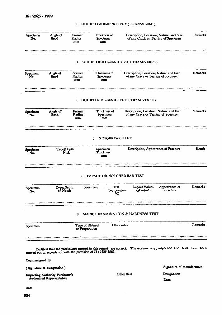
3. GUIDED FACE-BEND TEST ( TRANSVERSE )
SPg- Angle of Bend
Former ThicJmess of Radius Specimen
mm mm
Description, Location, Nature and Size of any Crack or Tearing of Specimen
RemarkI
. . . . . . . . . . . . . . . . . . . . . . . . . . . . . . . . . . . . . . . . . . . . . . . . . . . . . . . . . . . . . . . . . . . . . . . . . . . . . . . . . . . . . . . . . . . . . . . . . . . . . . . . . . . . . . . . . . . . . . . . ..........................................
4. GUIDED ROOT-BEND TEST ( TRANSVERSE )
SPg- Angle of Former Thickness of Description, Location, Nature and Size Remarks . Bend wu Specimen of any Crack or Tearing of Specimen
mm mm
. . . . . . . . . . . . . . . . . . . . . . . . . . . . . . . . . . . . . . . . . . . . . . . . . . . . . . . . . . . . . . . . . . . . . . . . . . . . . . . . . . . . . . . . . . . . . . . . . . . . . . . . . . . . . . . . . . . . . . . . . . . . . . . . . . . . . . . . . . . . . . . . . . . . . . . . . . . . . . . . . . -
5. GUIDED SIDE-BEND TEST (TRANSVERSE )
sea A&of Former Thicknesd of Description, Location, Nature and Size Rema& . Radius Specimen of any Crack or Tearing of Specimen
mm mm
. . . . . . . . . ..a................. . . . . . . . . . . . . . . . . . . . . . . . . . ..*......................................................................................................... --
6. NICK-BREAK TEST
SPg” .
Description, Appearance of Fracture Result
. . . . . . . . . . . . . . . . . . . . . . . . . . . . . . . . . . . . . . . ..*....................................................................... . . . . . . . . . . . . . . . . . . . . . . . . . . . . . . . . . . . . . . ..a.......
-
7. IMPACT OR NOTCHED BAR TEST
. . . . . . . . . . . . . . . . . . . . . . . . . . . ..*..*...... . . . . . . . . . . . . . . . . . . ..*............... . . . . . . . . . . . . . . . . . . . . . . . . . . . . . . . . . . . . . . . . . . . . . . . . . . . . . . . . . . . . . . . . . . . . . . . . . . . . . . . . . . . . . . .
8. MACRO EXAMINATION 6 HARDNESS TEST
specimen. Observation Remarks
. . . . . . . . . . . . . . . . . . . . . . . . . . . . . . ...*.. . . . . . . . . . . . . . . . . . . . . . . . . . . . . . . . . . . . . . . . . . . . . . . . . . . . . . . . . . . . . . . . . . . . . . . . . . . . . . . ..‘................‘.....~......................
&rti6cdth8ttheparticuhuIcnteredinti rt rx
are correct. The war-p, inspectiOn and teata have been &d out in dee with the pro&ion of IS : 2 5.1969.
OKice seal
Signature of mun&turcr
Designation
titc
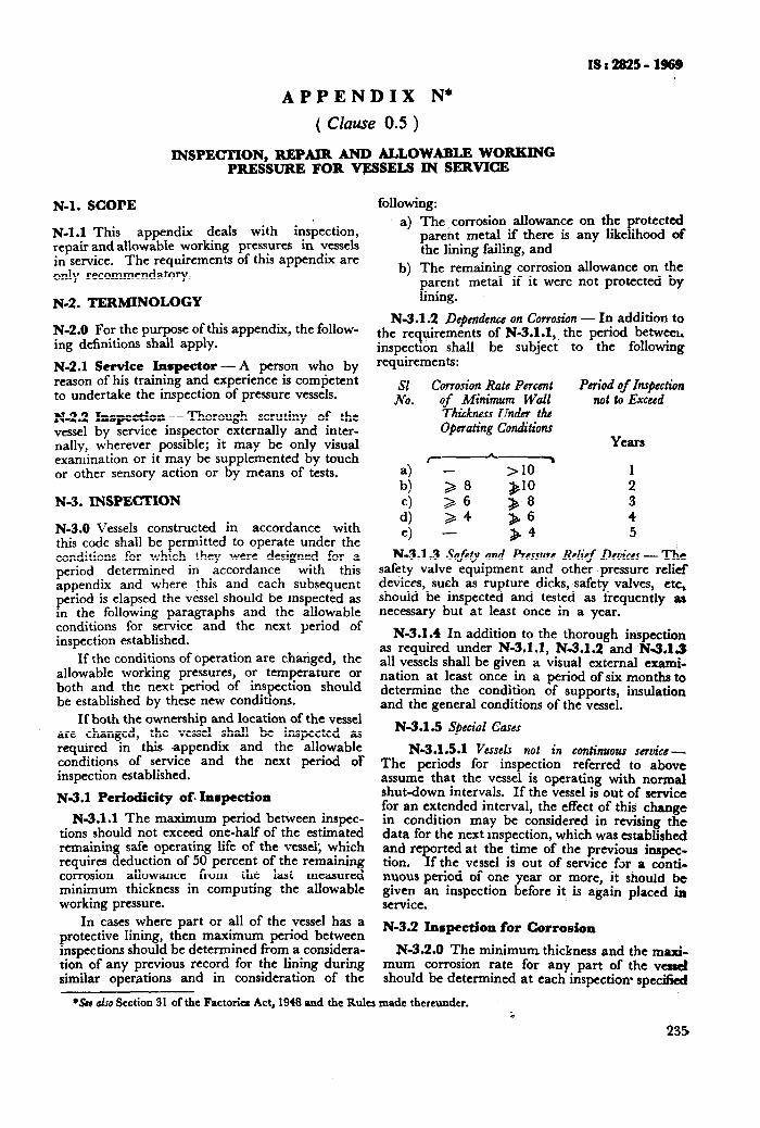
ISr2S25- 1969
APPENDIX N*
( CZause 0.5 )
INSPECTION, REPAlR AND ALLOWABLE WORKING PRESSURE FOR VESSELS IN SERVICE
N-l. SCOPE
N-l.1 This appendix deals with inspection, repair and allowable working pressures in vessels in service. The requirements of this appendix are only recommendatory.
N-2. TERMINOLOGY
N-2.0 For the purpose of this appendix, the follow- ing definitions shall apply.
N-2.1 Service Inspector-A person who by reason of his training and experience is competent to undertake the inspection of pressure vessels.
N-2.2 Inspcetion - Thorough scrutiny of the vessel by service inspector externally and inter- nally, wherever possible; it may be only visual examination or it may be supplemented by touch or other sensory action or by means of tests.
N-3. INSPECTION
N-3.0 Vessels constructed in accordance with this code shall be permitted to operate under the conditions for which they were designed for a period determined in accordance with this appendix and where this and each subsequent period is elapsed the vessel should be inspected as in the following paragraphs land the allowable conditions for service and the next period of inspection established.
If the conditions of operation are changed, the allowable working pressures, or temperature or both and the next period of inspection should be established by these new conditions.
If both the ownership and location of the vessel are changed, the vessel shall be inspected as required in this appendix and the allowable conditions of service and the next period of inspection established.
N-3.1 Periodicity of. Inspection
N-3.1.1 The maximum period betkeen inspec- tions should not exceed one-half of the estimated remaining safe operating life of the vessel, which requires deduction of 50 percent of the remaining corrosion allowance from the last measured minimum thickness in computing the allowable working pressure.
In cases where part or all of the vessel has a protective lining, then maximum period between inspections should be determined from a considera- tion of any previous record for the lining during similar operations and in consideration of the
following: a) The I corrosion allowance on the protected
parent metal if there is any likelihood of the lining failing, and
b) The remaining corrosion allowance on the parent metal if it were not protected by lining.
N-3.1.2 DcpmdcncG on Corrosion - In addition to the requirements of N-3.1.1,. the period betweel. inspection shall be subject to the following requirements:
SI Corrosion Rate Percent Period of Inspection NO. of Minimum Wall not to Exceed
Thickness Unab the O@rating Conditions
Years r-L-%
:] ,8 >lO 1
$6 $10 2
:; 24 &6 & 8 3
4
e> - 34 5
N-3.1.3 Safety and Pressure Relief Devices - The safety valve equipment and other pressure relief devices, such as rupture dicks, safety valves, etc, should be inspected and tested as frequently as necessary but at least once in a year.
N-3.1.4 In addition to the thorough inspection as required under N-3.1.1, N-3.1.2 and N-3.1.3 all vessels shall be given a visual external exami- nation at least once in a period of six months to determine the condition of supports, insulation and the general conditions of the vessel.
N-3.1.5 SpCt;ol Cases
N-3.1.5.1 Vesset not in continuous service- The periods for inspection referred to above assume that the vessel is operating with normal shut-down intervals. If the vessel is out of service for an extended interval, the effect of this change in condition may be considered in revising the data for the next inspection, which was established and reported at the time of the previous inspec- tion. If the vessel is out of service for a conti- nuous period of one year or more, it should be given an inspection before it is again placed in service.
N-3.2 Inspection for Corrosion
N-3.2.0 The minimum. thickness and the ma& mum corrosion rate for any part of the verrcl should be determined at each inspection- speci!iesJ
*SUN also Section 31 of the Factoria Act, 1948 and the Rules made thereunder.
235
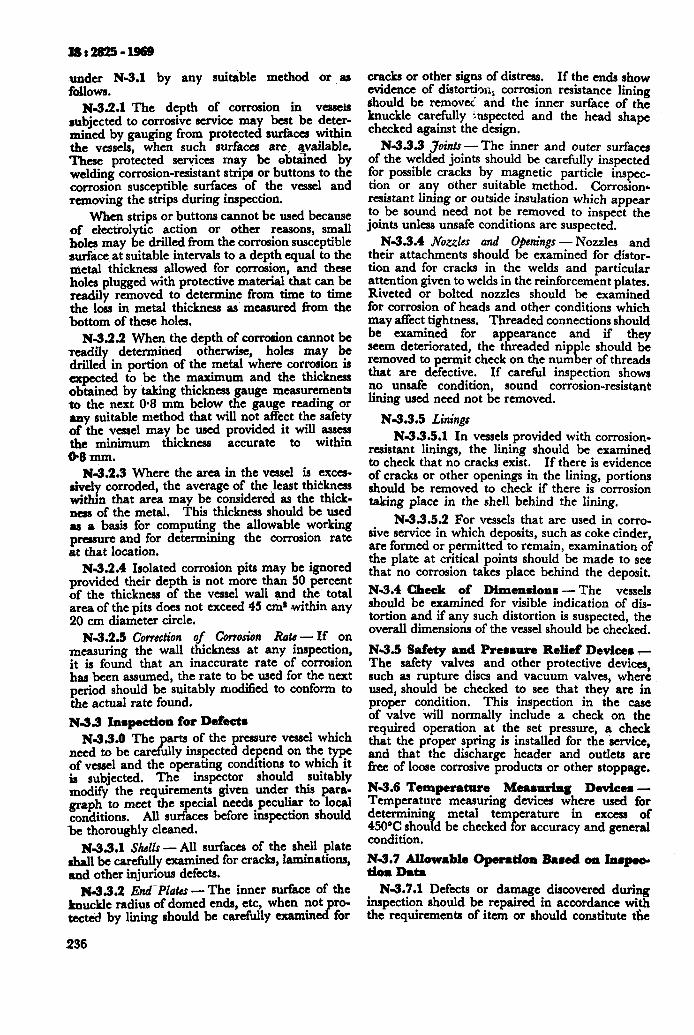
under N-3.1 by any suitable method or as follows.
N-3.2.1 The depth of corrosion in vessels subjected to corrosive service may best be deter- mined by gauging from protected surfaces within the vessels, when such surfaces are. available. These protected services may be obtained by welding corrosion-resistant strips or buttons to the corrosion susceptible surfaces of the vessel and removing the strips during inspection.
when strips or buttons cannot be used because of electrolytic action or other reasons, small holes may be drilled from the corrosion susceptible surface at suitable intervals to a depth equal to the metal thickness allowed for corrosion, and these holes plugged with protective material that can be readily removed to determine from time to time the loss in metal thickness as measured from the bottom of these holes.
N-3.2.2 When the depth of corrosion cannot be readily determined otherwise, holes may be drilled in portion of the metal where corrosion is expected to be the maximum and the thickness obtained by taking thickness gauge measurements to the next 06 mm below the gauge reading or any suitable method that will not affect the safety of the vessel may be used provided it will assess the minimum thickness accurate to within 08 mm.
N3.2.3 Where the area in the vessel is exces- sively corroded, the average of the least thickness within that area may be considered as the thick- nes of the metal. Thii thickness should be used as a basis for computing the allowable working pressure and for determining the corrosion rate at that location.
N-3.2.4 Isolated corrosion pits may be ignored provided their depth is not more than 50 percent of the thickness of the vessel wali and the' total area of the pits does not exceed 45 ems within any 20 cm diameter circle.
N3.2.5 Comction of Corrosion Rats- If on measuring the wall thickness at any inspection, it is found that an inaccurate rate of corrosion has been assumed, the rate to be used for the next period should be suitably modified to conform to the actual rate found.
N-3.3 Inqection for Defects N-33.0 The parts of the pressure vessel which
need to be carefully inspected depend on the type of vessel and the operating conditions to which it is subjected. The inspector should suitably modify the requirements given under this para- graph to meet the special needs peculiar to local conditions. All surfaces before inspection should be thoroughly cleaned.
N3.3.1 SM.r -All surfaces of the shell plate shall be carefully examined for cracks, laminations, and other injurious defects.
N-3.3.2 End-Plates-The inner surface of the knuckle radius of domed ends, etc, when not ro- tecte’d by lining should be carefully atamin J for
236
cracks or other signs of distress. If the ends show evidence of distortion, corrosion resistance lining should be removed and the inner surface of the knuckle carefully inspected and the head shape checked against the design.
N3.33 3oint.r - The inner and outer surfaces of the welded joints should be carefully inspected for possible cracks by magnetic particle inspec- tion or any other suitable method. Corrosion6 resistant lining or outside insulation which appear to be sound need not be removed to inspect the joints unless unsafe conditions are suspected.
N-3.3.4 JVo.&s aad Ojmings - Nozzles and their attachments should be examined for distor- tion and for cracks in the welds and particular attention given to welds in the reinforcement plates. Riveted or bolted nozzles should be examined for corrosion of heads and other conditions which may affect tightness. Threaded connections should be examined for appearance and if they seem deteriorated, the threaded nipple should be removed to permit check on the number of threads that are defective. If careful inspection shows no unsafe condition, sound corrosion-resistant lining used need not be removed.
N3.3.5 Linings N-3.3.5.1 In vessels provided with corrosion-
resistant linings, the lining should be examined to check that no cracks exist. If there is evidence of cracks or other openings in the lining, portions should be removed to check if there is corrosion taking place in the shell behind the lining.
N-3.3.5.2 For vessels that are used in corro- sive service in which deposits, such as coke cinder, are formed or permitted to remain, examination of the plate at critical points should be made to see that no corrosion takes place behind the deposit.
N-3.4 Check of Dimensions -The vessels should be examined for visible indication of dis- tortion and if any such distortion is suspected, the overall dimensions of the vessel should be checked,
N-3.5 Safaty and Prerrure Relief De&em T- The safety valves and other protective devices, such as rupture discs and vacuum valves, where used, should be checked to see that they are in proper condition. This inspection in the case of valve will normally include a check on the required operation at the set pressure, a check that the proper spring is installed for the service, and that the discharge header and outlets are free of loose corrosive products or other stoppage.
N-3.6 Temperature Mearuring Devicea- Temperature measuring devices where used for determining metal tern erature 450% should be checked or accuracy and general P
in excess of
condition.
N&7fJ$mble Opeawioa Raned on Inrpec-
N-3.7.1 Defects or damage discovered during inspection should be repaired in accordance with the requirements of item or should constitute the
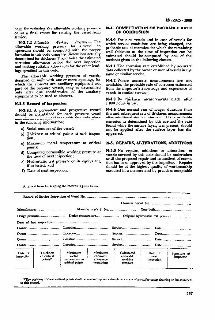
basis for reducing the allowable working pressure or as a final resort for retiring the vessel from service.
N-3.7.2 Allowable ’ Pressure - The allowable working prE?:zg for a vessel in operation should be computed with the proper formulae in this code using the dimensions actually’ determined for thickness ‘t’ and twice the estimated corrosion allowance before the next inspection and making suitable allowances for the other load- ings specified in this code.
The allowable working pressure of vessels, designed or built with one or more openings, for which the closures are auxiliary equipment not part of the pressure vessels, may be determined only after due consideration of the awhary equipment to be used as closures.
N-3,8 Record of InBpection
N-3.8.1 A permanent and progressive record should be maintained for each pressure vessel manufactured in accordance with this code given in the following information:
4 b)
4
4
4
f)
Serial number of the vessel;
Thickness at critical points at each inspec- tion; &,ximum metal temperature at critical points; Computed permissible working pressure at the time of next inspection; Hydrostatic test pressure or its equivalent, if so tested; and Date of next inspection.
A typical form for keeping the records is given below:
ISr2825-1888
N-4. COMPUTATION OF PROBABLE RATE OF CORROSION
N-4.0 For new vessels and in case of vessels for which service conditions are being changed! the probable rate of corrosion for which the remaining wall thickness at the time of inspection can be estimated should be computed by one of the methods given in the following clauses.
N-4.1 The corrosion rate established by accurate data collected by the owner or user of vessels in the same or similar service.
N-4.2 Where accurate measurements are not available, the probable rate of corrosion estimated from the inspector’s knowledge and experience of vessels in similar service..
N-4.3 By thickness measurements made after 1000 hours in use.
N-4.4 One normal run of longer duration than this and subsequent sets of thickness measurements after additional similar intervals. If the probable corrosion is determined by this method the rate found while the surface layer, was present, should not be applied after the surface layer has dis- appeared.
&-!I. REPAIRS, ALTERATIONS, ADDITIONS
N-5.0 No repairs, additions or alterations to vessels covered by this code should be undertaken until the proposed repair and its method of execu- tion has been approved by the inspec’to. Repairs should be of the highest quality of workmanship executed in a manner and by practices acceptable
&cord of Service Inspections of Ve~lel No .................................................................................................
Owner’s Serial No. ................................... .
M~ufacturct ................................. Manufacturer’s Sl No. ........................ Year built .................................
De&P- ........................ Design temperature.. ................... Original hydrostatic
Date of last inspection.. ........................................
Chvna .............. ..‘...., ........ Location.. ............................ Service.. .........................
w.. ............................ Location .............................. Strviu ...........................
...................... . ....... Location .............................. Service ...........................
Owner.. ............................ Location.. ............................ Serviu.. .........................
tat prenure.. ................
Date ...........................
Date. ..........................
Date ...........................
Date.. .........................
Date of mqection
Thickness at critical
points’
Maximum Maximum Calculate-d metal corrtion allowable
temperature at allowance critical points remaining
working p&sure
Date of next.
inspection
Signature 05 Inspector
I * -- I
me position of thtye critical points shall be marked up on a sketch or a copy of manufacturing drawing to be at u&d to tllis record.
23’t
xsr2825-1969
under the provisions of this code and under proper supervision. Complete records of repairs, altera- tions and additions shall be made and maintained for future reference.
All welding should be done by qualified welding operators who have demonstrated their ability to meet all requirements of the welding and under conditions that will prevent excessive stress developing in the vessel. Where we!ding has been done on vessels that have been stress-relieved in accordance with the provision of this code, the parts affectedshould be stress-relieved wherever it is required by this code. If stress-relieving is not required and is not done, the joint efficiency bhould conform to that permitted for a class 3 ,vessel.
N-5.1 Welded Joints and Plates-Repairs to welded joints, cracks and to.minor plate defects may be made after chipping out a U- or V-shaped groove to the full depth and ’ length of the crack by filling this groove with weld metal.
N-5.2 Corrosion Pito - Isolaned corrosion pits may be chipped out to sound metal and filled up by weld metal.
N-5.3 Corroded or Distorted Flange Faces - Corroded flange faces should thoroughly be cleaned and built up with wel,d metal and remachined in place to a thickneSs not less than that of the original flange. Corroded flanges may also be remachined in place without building up with weld metal, provided that all metal removed in the process comes from a raised face and does not reduce the thickness of the main portion of the &urge.
N-5.3.1 Warped Flanges -Warped flanges which cannot be remachined or flanges which have become’distorted due to excessive tightening of the flange bolts should be replaced with new flanges welded on in accordance with the require-
.’ ments of this code.
N-5.4 Cracks at Tapped Opening-Repairs to cracks at a tapped opening merely by chipping out, welding or re-tapping is not recommended.
238
A fully reinforced flange nozzle may be in- stalled, or if a tapped connection is required it may be provided by welding in a section of seam- less tubing for the full depth of the plate of length at least twice the plate thickness and at least 25 mm in diameter larger than the tapped opening, or by other adequate reinforcing.
N-5.5 Application of Patches of Vessels by Weldine
N-5.5.1 Patches to be welded to vessel walls should meet the same specifications as the plate to be repaired. All details of the welding procedure should conform to those followed in welding the main joint of the vessel. If the patch is to be inlaid in a seamless section, a stress-relieved double welded butt joint should be made. Care should be exercised to prevent cracking.
If the patch is to be applied as an overlay, welding should be performed in the same manner as for a reinforcing plate around an opening and the proportion of the patch being determined. in accordance with this code. The application of patch plates to both the outside and inside of the vessel wall is preferred to a single overlaid plate. Overlaid patches attached by welding should be limited to wall thickness not over 16 mm.
N-5.5.2’ Alterations or new connections that may be installed on vessels shall conform to the requirements of this code as regards the design, location and method attachment.
N-6. HYDROSTATIC TEST
N-6.1 Where it is not possible to inspect the interior of the vessels as required under 3, it should be subjected to a hydrostatic test or equivalent.
N-6.2 A vessel which has undergone repairs or alterations and which in the opinion of the inspector is of sufficient magnitude to affect its safety should be given hydrostatic test or equi- valent in accordance with the provisions of this code.
AMENDMENT NO. 1 SEPTEMBER 1977
TO
IS : 2825-1969 CODE FOR UNFIRED PRESSURE VESSELS
Alterations
[ Page 18, clause 3.4.2 (c) ] - Substitute ‘ Torispherical ‘for ‘ Dished and flanged ‘.
[ Page 19, caption of Fig. 3.3 (C) ] - Substitute ‘ Toriwherica\ End* ’ for 6 Dished and Flanged Ends ‘_
( Page 21, clause 3.4.5, Note 2, line 3 ) - Substitute ‘ ,,tx ’
‘dV\/t.D,’ at both the places.
( Page 24, clause 3.6.1.1, dcJinition of symbol D ) - Substitute following for the existing definition:
‘ D = diameter or short span measured as in Table 3.7, in mm; ‘.
the
[Page 33, clause 3.0.5.2 (b) (3), definition of Jymbol H2, line 6) -
Substitute ‘ lid(t--2c)‘for‘~/;i(t--ZC)‘.
(Page 43, clause 4.4, dejnition of symbol A ) - Substitute ‘ mm ’ for ‘ mms ‘.
( Page 43, clause 4.4, deJinition of symbol CF)- Substitute the following for the existing matter:
‘ CF = bolt pitch correction factor
E bolt spacing 2. ( bolt diameter ) + t
The value of CF shall be, however, not less than 1. ’
( Page 44, clause 4.4 j - After the definition of symbol FL and before the sign of equality ‘ = ‘*insert the notation ‘f ‘.
( Page 44, clause 4.4, dqhition of Jymbol G, line 7 ) -SubstitWe ‘6, > 6’3 mm ’ for ‘ b > 6’3 mm ‘.
[ Page 46, Fig. 4.1 (B) ] - Substitute ‘ h, ‘for ( h, ‘.
[Page 46, Fig. 4.1 (E), (F), (G) ] a) Add the following caption above the figures:
‘ INTEGRAL-TYPE FLANGES ’
b) Substitute ‘ h, ‘for ‘ h, ’ and ‘ HT ‘for ‘ H, ‘.
Gr 1 1
( Page 47, Fig. 4.2 ) - Substitute ’ b. < 6.3 mm ‘for ’ b,, = 6.3 mm ‘.
( Pages 54 and 55, Table 4.2, col I and II ) - Substitute ‘ W ’ for Cw ’ and ’ T’for ’ 25 I’.
( Page 67, clause 6.4.2.3, last sentence) - Substitute the following for the existing sentence:
’ When plates are flame-cut, the edges should be examined, as far as possible, immediately after this operation. ’
(Page 72, clause 6.6.6, second sentence ) - Substitute the following for the existing sentence:
‘ Unless otherwise specified the out of straightness of the shell shall not exceed 0.3 percent of the total cylindrical length in any 5 m length. ’
( Page 75, clause 6.12.2.5, line 8 ) - Substitute ’ physical properties ’ for ’ yield point ‘.
( Page 78, clause 6.12.4.2, line 5 ) - Substitute ‘ weld ‘for ‘ shell ‘.
[Page 103, clause 8.7.1.1 (c), line 4 ] - Substitute ‘ 19 mm ‘for ‘20 mm’.
( Page 167, Table C.5, last tow ) - Substitute ’ -$‘for ‘ f ‘.
( Page 167, clause C-4.3.2.4, dejinition of fn ) - Substitute the following for the existing matter:
‘fn = ~00 C/2t x 100 in which C is the shape factor from Fig. 3.7. ’
[ Page 168, equations ( C. 19 ) and ( C.20 ) J -- Substitute ‘ I ’ for ‘ 1’ at both the places.
( Page 181, clause F-4.1, dsJinition of symbol I,, line 2 ) - Substitute ‘ cm4 ‘for ’ mm” ‘.
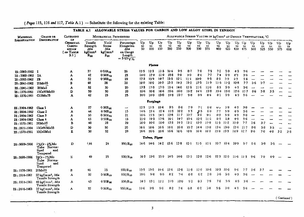
(Pup115, 116nd117,~ubkA.1) - Substitute the following for the existing Table:
TABLE A.1 ALLOWABLE STRESS VALUES FOR CARBON AND LOW ALLOY STEEL IN TENSION
MATEBIAL GBADB 0B CATEOOBY S~OITIOATION DESIBHATION
Cli~ZXL COMPO- SITION
( see TABLPJ B.1 )
Is : 2002- 1962 I IS : 2002.1962 2A Is : 2002-1962 2B IS : 2041-1962 2OMo55
IS : 2041-1962 20Mn? IS : 1570-1961 15Cr9OMo55 18: 1570-1961 Cl5Mn75
IS : 20041962 Class I I8 : 20041962 Clam 2 I8 : 2004-1962 Class S I8 : 2004-1962 Class 4 Is : 1570-1961 20Mo55
18 : 2611.1964 15Cr9&o55 I8 : 1570-1961 lOCr2Mol
IS : 3609-1966 1 %Cr - )%Mo Eu$ Norma-
and Tempered
Is : 3609-1966 2tcr - l%Mo Tube Norma- lized end Tempered
I8 : 1570-1961 20Mo55
IS : 1914-1961 32 kgf/mm2, Min Tensile Strength
IS : 1914-1961 43 kgf/mm2, Min Tensile Strength
IS : 2416-1963 32 kgflmmg, Min Tensile Strength
A A A B
A D A
A A A A B
D E
D
E
B
A
A
A
ME~EANICAL PEO~ERTIES ALLOWABLE Sraxss VALVES IN kgQmm2 ATDESIQN TEMPERATURE,"~ ~__--_-h___-~ ~__-d-----__-_~-_4 ------.------------___ ‘Tensile Strength
hfin kgf/mm*
ho
37 42 52 48
52 50 42
Yield Stress Mi?r
kgf/mma Bzo
W55Rao @50R40 0’50Ra0
28
so so 2s
Percentage Elongation
Min on Gauge
Length = 5*65~/5
up UP UP UP UP UP UP UP UP UP UP UP UP UP UP‘ to
yJ UP
50 1’:o 1: 2% 2% &I ;5” S% 400 4% 4& 4:o 5?0 5’;; 5% 5f705 $0
Plates
26 25 20 20
20 20 25
12.3 12.3 11.5 10.4 95 8.7 7.8 7.5 7.2 5.9 4.3 3.6 - - - _ - 14.0 12.9 11.9 10.8 9.8 9.0 8.1 7.7 7’4 5.9 (‘3 3’6 - - - - - 17.3 15’9 14.7 13.3 12’1 11’1 10.0 9*5 8.3 5.9 4.3 3.6 _ _ _ - _ 16.0 16.0 16.0 15.3 14.3 13.2 12.3 11.9 11.5 11.2 .10.8 7.7 5.6 3.7 - - _
l?S 17.3 17.0 15.4 14.0 12.8 11.6 lJ;O 8.3 5.9 4.3 3.6 - - - - - 16.6 16.6 l&6 16.6 16.0 15.2 14’4 13.8 13.4 13.0 12.6 11.7 8.6 5.8 3.5 - - 14.0 14.0 IS*0 11.8 10.7 9.8 8.9 8.4 8.1 5.9 4.3 3,6 - - - - _
Forginga
37 0.50Rz,, 44 O.50Rtr, 50 0*50Ra,, 63 0*50Rz,, 48 28
50 so 50 32
15 21 15 20
20 20
12.3 11.3 10.4 9.5 8.6 7.9 7’1 6.8 o.3 5.9 4.3 3.6 - - - _ _ 14.6 13.4 12.4 11.3 10.2 9.3 3.5 6 0 7.7 5.9 4.3 36 - - _ - _ 16.6 15.3 14-l 12.8 Il.*7 10.7 9.6 9.1 8.3 5.9 4.3 3.6 - - ._ - _ 21.0 19.3 17.8 16.1 14’7 13.4 12.2 11.5 8.3 5.9 4.3 3.6 - - - _ _ 16.0 16.0 16.0 15.3 14.3 13,2 12.3 11.9 11.5 11.2 10.8 7.7 5.6 3.7 - - _
16.6 16.6 16.6 l&6 16.0 15.2 14.4 13.8 13.4 13.0 12.6 11.7 8.6 5.8 3.5 - _ 16.6 16.6 16.6 16.6 16.6 16’6 16.4 16.1 15.8 15.3 14’9 12.7 9.6 7.0 4.9 3.2 2.3
T&es, Pipem
a‘44 24 950/Rzo 14.6 146 14.2 13 6 12&8 12.1 11.5 11.1 lox7 10.4 10’0 9.7 8.6 5.8 3.5 - -
49 25 95O/R2o 16.3 15’6 15.0 14.5 14-O 13.5 12.8 12.6 12’3 12.0 11.6 11.3 9.6 7.0 4.9 - -
46 25 95O/Rzo
32 0.50Rze 950/Rzo
43 0*50Rae 95O/Rzo
32 O’5OR2,, 950/&o
15.3 15.3 14.6 13,6 12.8 11.8 11.0 10.6 10’3 10.0 9.6 7’7 5.6 3.7 - - -
10.6 9.8 9.0 82 7.4 6.8 6.2 5.8 5.6 5.0 4.3 3.6 - - - - _
14.3 13.1 12.2 11.0 10’0 9.2 8.3 7.9 7.6 5.9 4.3 3.6 - - - - _
10.6 9.8 9.0 8.2 7.4 6.8 6.2 5.8 5.6 5.0 4.3 3.6 - - - _ _
( Continueff )
3
”
TABLE A.1 ALLOWABLE STRESS VALUES POH CARBON AND LOW ALLOY STEEL IN TENSION -Co&
CATEQORY
CBEzm COMPO- aIT.ION
(xc TABLE B.1)
MECHANICAL PROPERTIES ALLOWABLE STRESE VA~.UES IN kgf/mms AT DESIQN TEPPERATURE, “C ~-_-__----.h____ ----\ r_---_--,--,-_--------_-~-,, ___--_--‘______ Tensile
Strength Min
kgf/mms Rzo
Yield Stress Min
kgf/mms B 20
Percentage . Elongation
DP UP UP
Min & on Game
:o”o l?o
UP UP UP
26”O IZO 3’00
UP
3&
UP UP
3t705 4%
Length- = 5.65j/x
UP
4F5
;I;
;:;
5.9 5.9 5.9
4.4 7.5
9”::
11’1 140
::4”
5.9 5.9
5.9 59 5.9 5.9 5.9
MATERIAL GRADE OB SPEOIFIOATION DESIGNATION
UP
5%
UP
5;
31.6 176 33.7 19.7 33.7 21.1 42.2 24.6
42’2 29.5 44.3 32.3 46’4 366
-
10’5 10’5 9.9 11.2 11’2 11.2 11’2 11’2 11.2 14.0 14-o 13.9
i4’0 140 1Y’U 14.7 1+7 147 15*4 15.4 154
9.0 8.2 7.5 10.1 9.2 84 10.8 9.8 9.0 12% 11’5 10.5
- - -
14.0 13’8 12.6 14.7 14.7 13.8 15.4 15.4 15.4
6.7 7.6
;::
11.5 12.5 141.
6.4 6.2
77.27 . 6.g .
9.0 z
10.8 8’3 11.8 8.3 13.4 8.3
UP
5’n”O
- -
- -
-
-
-
- -
-
-. -
castings*
35
32;
32: 43
21 25
17 17 15
:: 15
20 18
13.7 13.7 137 11.7 11’6 11.0 13.0 13.0 13’0 12’2 12.2 12.2 13.0 13.0 13-o 15.7 !5’7 15.7
10.5 9.6 8’9 12.2 11.5 10.6
96 62 :I: 9.6 7.7
11.9 11.2 10.6 13.0 13.0 12.5 15.7 15’7 15.7
10.1 8.2
10.2 10.1 11.9 15.5
;;
2.7
2:;
8.5 5.5 6,7
2.7 2.7
4-2
f5”
7.2 4.9
::f
-
;Tb 37 2.6
80 7.3 67 9.6 8.7 8.0
Rivet and Stay Bars
37 42
055&e 0*55Rs0
26 12.3 12.3 11.5 10.4 8-6 7.9 23 140 140 13.1 11.8 9’8 9’0 8’:;
6.8 6.5 7.9 7.4
36 3.6
Sectiorss, Plates, Ban
42 24 23 50 29 20
42 23 23
- -
-
UP
f%
-
-
-
;9
-
- - -
37 42 44
;;
0*50Rso 0.50Rso 0.50Rso 0*50R,, 0’50Rs0
22845
14.0 14’0 13.6 123 9’8 9-O 16’6 16.6 16.4 148 11.7 107
14-O 14.0 13-O 11.8 9.8 9.0
14.0 140 13.0 11.8 9.8 9.0 146 166 16.4 14.8 11.7 107
12.3 11.3 10.4 9.5 8% 7.9 14.0 12.9 11.9 10.8 9.8 9.0 14.6 13.4 12.4 11.3 10.2 9.3 156 144 13.3 12.1 Il.0 100 16’6 15.3 14.1 12.8 11.7 107
14.6 14.6 136 12.3 9.8 9.0 16.6 16.6 16.1 146 11.7 IO.7
8.1 9.6
8.1
81 96
7’1
88::
9-l 9.6
;:;
- - - -
- -
- - - _
6’8 6.5 7.1 I.4
;:!j ;:;
9.1 8.3
- - - -
3.6
3”:;
3.6 3-6
- -
- - -
-
-
- - -
-
-
- - -
-
UP
5?5
?4 1.7
-.
-
-
- -
-
-
- - -.
IS: 1978-1961 St 18 St 20 St 21 St 25
- -
IS : 1979-1961 St 30 St 32 St 37
IS : 3038-1965 Grade 1 Grade 2 Grade 3 Grade 4 Grade 5 Grade 6
IS : 2856-1964 g ;,w-;;;
h B C
i F
A A
IS : 1990-1962
IS : 226-1962 St 42-S
IS : 961-1962 St 55 HTW
IS : 2062-1962 St 42-W
IS : 3039.1965 2;;;; D”
IS : 3503-1966 Grade 1 Grade 2 Grade 3 Grade 4 Grade 5
IS : 3945-1966 Grade A-N Grade B-N
A A
A
A A
A
::
2
A”
-
*These values have been based on a quality factor of 0.75. proportionally.
For additional inspeLtion as detailed in Note to Table 2.1, a quality factor of 0.9 shall be used and the above stress values increased
(EDC 48) 4
PrInted at Kay Kay Printers. Delhi
AMENDMENT NO. 2 OCTOBER 1978 TO
IS : 28=- 1969 CODE FOR UNFIQED PRESSURE VESSELS
Alterations
Sl A%.
1. (Page 6, clause 1.3.1.1. para 2 ) - Substitute the following for the existing paragraph:
‘All welded joints of Class 1 vessels shall meet the requirements stipulated in co1 3 of Table 1 .l. All butt joints shall be fully radiographed. Circumferential butt joints in nozzles, branches and sumps not exceeding 170 mm outside diameter or 19 mm wall thickness need not be radiographed ( see 8.7.1.1) except for vessels that are to contain lethal* or toxic substances.’
2. ( Page 6, clause 1.3.1.1, ~arus 4 and 5 ) - Substitute the following for the existing paragraphs:
‘a) Catepory A - Longitudinal welded
b)
join& within the main shell, commu- nicating chambers?, transitions in diameter, or nozzles; any welded joint within a sphere, within a formed or flat head, or within the side plates of a flat sided vesse!; circum- ferential welded joints connecting hemispherical heads to main shells, to transitions in diameters, to nozzles, or to communicating chambers?. Category B - Circumferential welded joints within the main shell, commu- nicating chambers?, nozzles or transitions in diameter including joints between the transition and a cylinder at either the large or small end; circumferential welded joints connec- ting formed heads other than hemispherical to main shells, to transitions in diameter, to nozzles, or to communicating chamberst:’
3. [ Page 8, Table 1.1, against Sl .Nb, 3(b), co1 (5), (6) and (7) ]-Substitute the following for the existing matter in each of these columns:
‘ Maximum thick- ness 16 mm before corrosion allow- ance is added, and 18 mm after adding corrosion allowance ’
4. ( Page 11, clause 2.2.4 ) - Substitute the following for the existing clause: ‘2.2.4 Bearing Stress-The maximum per- missible bearing stress shall not exceed the allowable stress value.’
Sl JfO.
5. [ Page 11, dauie 3.1.3.1(c) ] -Substitute the following for the existing text:
‘c) Wind loading in combination with other loadings ( see C-4.1.3 ),
d) Seismic loads (see IS : 1893-1975* ).’ 6. ( Puge 11, foot-note ) - Add the follow-
7.
8.
9.
10.
11.
12.
13.
14.
ing new foot-note: ‘*Criteria for earthquake resistant design of
structures ( serond reuision ).’
( Page 12, clause 3.2.2 ) - Add the following note after the clause:
‘NOTE -All calculations in this Code are in corroded condition unless otherwise specified.’
( Page 12, clause 3.2.3, para 2 ) - Add the following at the end of the paragraph:
‘In such cases tell-tale holes, suitably disposed, shall be provided on the vessel wall SO that easy detection of leakage in welds in lining is made possible. They shall have a depth not less than 80 percent of the thickness required for a seamless shell of like dimensions or they may extend to the lining.’
( Page 13, clause 3.3.2.1, deJinition of symbol E ) - Delete the words ‘ see Tables 3.1, 3.2, 3.3 and 3.4 )‘.
( Page 13, clause 3.3.2.4, deJinition of symbols E, E, ) - Delete the words ‘ ( see Tables 3.1, 3.2, 3.3 and 3.4 )‘.
( Page 14, Tables 3.1,3.2,3.3 and 3.4 ) - Delete.
( Page 15, clauses 3.3.3 and 3.3.3.1 )- Substitute the following for the existing clauses:
( 3.3.3 Shells Subjected to Extend Pressure
3.3.3.1 The thickness of shelh subjected to external pressure shall be calculated by the method given in Appendix F.’
[ Page 15, clauses 3.3.3.2, 3.3.3.3, 3:3;“,‘“’ and 3.3.3.4(b) ] - Delete these
.
( Page 16, new c1aus.e 3.3.3.2 ) - Add the following new clause 3.3.3.2 at the top of the page:
‘3.3.3.2 S@ning rings - Stiffening rings are generally used with cylindrical shells subjecte, to external pressure. They extend around the circumference of the shell and may be located on the inside or the outside of the shell.’
Gr 1
1
Sl d\m.
15. [ Page 16, clause 3.3.3.4(c) ] - Re- number the clause as 3.3.3.2(a).
16. [ Page 17, clartse 3.3.3.4(d) ] - R’e- number the clause as 3.3.3.2(b).
17. [ Page 17, rla~~e 3.3.3.4(d) (l), renum- bered as clause 3.3.3.2(b) (1) ] - Substitute the following for the existing text:
‘1) the total length of intermittent wcldiIlg on each side of the stiffening ring shall be not less than one-half the outside circumference of the vessel, for stiffening rings situated on the outside. However, at any location of the stiflening ring there shall be welding between the shell and at least one side of the stiffening rin,e. The maximum unwelded length ;on side shall not exceed 8 timrs vessel thickrless for external rings 12 times the vessel thickness internal rings as shown below:
any fhe ,I
and ’ for
18. [ Page 17, clause 3.3.3.4(e) ] - Renum- ber the clause as 3.3.3.3.
19. ( Page 17, clause 3.3.3.5 ) - Renumber the clause as 3.3.3.4.
20. ( Page 30, clause 3.8.5.1 ) - Substitute the following for the existing clause:
‘3.8.5.1 General - At all planes through the axis of the opening normal to the vessel surface the cross-sectional area requirements,for compensation as calculated below shall be satisfied:
Material in added compensation, or in a branch, should have similar mechani- cal and physical properties to that in the
Sl .NO.
vessel shell or end. It is recommended that compensation or fittings be made normally from material having an allow- able stress not less than 75 percent of the allowable stress for the material in the shell or end. Where material having a lolver allowable stress than that of the vessel shell or end is taken as compensa- tion its effective area shall be assumed to be reduced in the ratio of the allowable stresses at the design temperature. T\‘o credit shall be taken for the additional strength of material having a higher stress \-alue than that in the shell or end of the vessel.
Material added for compensation shall ha\ e approximately same coefficient of thermal expansion ( say 85 percent ). The thickness of compensating pad shall be limited to the nominal thickness of shell or head as relevant. -An)- area contributing to compensaticn shall be attached to shell or head by full penetra- tion welds.’
21. ( Pa,ge 35, infotmol table under dnrrs(, 3.8.9.1 ) - Substitute the follolving for the existing table:
( Branch .\bttlitrnl Si:t- .Ifittittrrtm Tltiiktt~~ss
22.
23.
24.
mm
15 20 25 3L’ 40 50 65 80
100 125 150 200 250 300 350 400 450 500 600
111111
2.4
"'4
2.7
3. 1 3.1 3.6 3.9 4.7 5.4
;:2”
6.9 8.0 8.0 8.8 8.8 8.8
10.0 IO.0
Nom-The value given in the table is to be increased by the amount of any required corrosion allowance.’
( Page 43, clause 4.1.3 ) - Substitute the following for the existing clause:
6 4.1.3 Hub flanges shall not be made by machininp; the hub directly from plate materials:’
(Pages 56, 61, 62, various sub-clauses of clause 5 ) - Substitute ‘ device ’ for ‘ valve ’ and ( devices ’ for ‘ valves ’ wherever it appears.
( Page 61, clause 5.4.1 ) - Substitute the following for the existing clause:
2
‘5.4.1 The total capacity of the relief device or devices fitted to any vessel or system of vessels shall be sullicient to discharge the maximum quantity of fluid, liquid or’gas, that can be generated or supplied without permit- ting a rise in vessel pressure of more than 10 percent above the maximum working pressure when the relief devices are discharging.’
25. ( Page 65, clause 6.2.1.3 ) - Substitute the .following for the existing clause:
‘6.2.1.3 The weld procedure and welders shall be qualified for the type of welding concerned in conformity with the weld procedure and welders’ performance qualifications ( see 7.1 and 7.2 ).’
26. ( Pages 65 and 66, &USC 6.3.2 I - Substitute the following for the existing clause:
‘6.3.2 In the design of all details the aim shall be. to avoid disturbances in the flow of the lines of force, in particular in constructions subjected to fatigue stresses. Holes and openings shall not be positioned on or in the heat affected zones of welded joints. Where such openings are unavoidable, such holes can be located on circumferential joints provided the main seams are ground Aush 75 mm on either side and radiography requirements given in 6.3.2(a) are met. However openings with added reinforcements should not have the hole cut on the weld seam.
a) The circumferential seam shall be radiographed, for a total length of three times the diameter of opening with the centre of whole at mid length. Defects thaf are completely removed in cutting the hole shall not be considered in judging the acceptability of the weld.’
27. ( Page 66, clause 6.3.2.1, second sentence ) - Substitute the following for the existing sentence:
‘Joints between cylindrical shells and domed end plates shall not be located in the curved part of the domed end except for hemispherical ends ( see Table 6.2 ),’
28. ( Page 67, clause 6.4.2.5 ) - Substitute the following for the existing clause:
‘6.4.2.5 Edges which have been flame- cut by hand shall be cut by machining or chipping for a distance not less than 1.5 mm.’
29. [ Page 7 1, clause 6.6.2(b) (2)) line 3 ] - Substitute ‘ 5 mm ’ fir ‘ 4 mm ‘.
30. ( Page 74, cIausc 6.7.16, lad sentence ) - Substitute the following for the existing sentence:
‘ In the case of light duty vessels the reinforcement shall be not more than 3 mm for thickness less than 10 mm, and 5 mm for thickness from 10 to 16 mm.’
31. [ Page 76, Table 6.3, co1 (3), para 2, line 4 ] - Insert the following between the words ‘ preheating ’ and ‘ for ’ :
‘ up to a minimum temperatttre of 150°C ’
:2. ( Page 76, Table 6.3, Foote 2, ?ine 1 ) - Substitute ‘ 16 mm ’ for ‘ 15 mm ‘.
33. ( Page 76, Table 6.3, Note 3, line 1 ) - Substitute ‘ 0°C ‘for ‘ -WC ‘.
34. [ Page 81, clause 7.1.3.4(e) ] - Substi- tute the following for the existing clause:
‘e) if in gas shielded metal arc (MIG) or tungsten arc (TIG) welding or submerged arc welding a change is made from multiple pass welding per side to single pass welding per side when notch toughness is a requirement.’
35. [ Pqe 81, clause 7.1.3.4(h) ] - Substi- tute the following for the existing clause:
‘h) if in gas shielded metal arc welding (MIG) or gas shielded tungsten arc welding (TIG) a change is made in the composition of the gas and a change in the electrode from one type to another or from non-consumable electrode to consumable electrode and vice uersa, or an increase of 25 percent or more or a decrease of 10 per- cent or more in the rate of flow of shielding gas.’
36. ( Page 81, clause 7.1.3.5 ) - Add the following new paragraph after the clause:
‘A change from downward to upward or vice versa in the progression for any pass of a vertical weld excepting the root pass which will be removed completely while preparing the second side and the cover pass, if notch toughness is a requirement, calls for requalification.’
37. ( Page 81, clause 7.1.4, jirst sentence ) -- Add the following new matter after the first sentence:
‘However, for temperatures less than 0°C the qualification shall be valid for thickness from 1 to 1.1 times the thick- ness of test piece.’
38. [ Page 82, clause 7.1.5(b), lines 3 and
41- Delete the words ‘one above the other,’
39. [Page 82, clause 7.1.5(c), lines 3, 4 and
51- Delete the words ‘ and where the
3
Sl No.
-30.
41.
42.
43.
‘14.
45.
46.
thickness of the plate permits, one shall be abo\-e the other ‘.
Sul,s[tifIg ’
2, &me 7.1.5(c)(l), lillf 2 ] - ‘2Omm’fof ‘30mm’.
( Page 87, Table 7.4, column of maximum range of thickness pa&d by test plate correspond- ing to thirkness of test plate ’ t 20 and over ’ )- Substitute ‘ 2 t ’ for ‘ 1.5 1’.
(Page 88, clause 7.2.6.4 ) -Add the following new clause after this clause:
‘7.2.6.5 Radiography is acceptable in place of mechanical testing for manual metal arc or gas shielded tungsten arc or combination processes.’
( Page 95, clause 8.4.2, line 1 ) - Delete the words ‘ in mild or low-alloy steels ’ .
[ Page 97, clauxe8.5.1.3(~), para 1, lines 3, 4 and 5 ] - Delete the words ‘ and where the thickness of plate permits, one shall be above the other ‘.
line iPage 97, clause 8.5.1:3(c), para - Substitute ‘ 20 mm for ‘ 30 mm
!I,
[ Page 97, clause 8.5.2.2(b), Jirst and second sentence ] - Substitute the following for the existing sentences:
‘ Two bend test specimens, one for direct and one for reverse bending to be taken transversely to the weld. Where the plate thickness exceeds 20 mm, face bend and root bend tests may be substituted by side bend tests.’
47. ( Page 100, clause 8.5.9.2, line 2 ) - Substitute ‘ 20 mm ’ for ‘ 30 mm ‘.
48. ( Page 100, clause 8.5.9.3, lines 2, 3 and
7)- In each of the lines, substitute ‘ 20 mm ’ for ‘ 30 mm ‘.
49. ( Page 101. clause 8.5.9.6 ) - Add the following new matter in the begisning:
c When specifically asked for by the customer ‘.
50. [ Page 103, clause 8.6.8.1(a) ]-- Ada the following new matter at the end:
‘For the transverse tensile test if the
(EDC 48)
Sl Y 0.
result exceeds 95 percent of the specifi- ed minimum value with fracture occurring ‘in base metal, the test is acceptable.’
51. ( Page 103, clause 8.7.1.2 ) -Delete.
52. ( Page 104, clause 8.7.4, last sendence ) - Substitute the following for the existing sentence:
‘ When image quality indicator of the wire.-type is used, the smallest diameter wire which can be seen in the radio- graph shall have a diameter not greater than 1.5 percent of the weld metal thickness if the weld metal thickness is between 10 and 50 mm inclusive, and not greater than 1.25 percent of the weld metal thickness if the thickness is between 50 mm and 200 mm, In the case of plate type penetrameters, the radiographic examination shall be capable of revealing a difference in metal thickness equal to not more than 2 percent of the thickness of weld under examination.’
53. (Page 109, clause 8.7.10.2, para 1 ) - Delete and renumber the second paragraph as ‘8.7.10.2’.
54. ( Page 110, clause 8.7.11,&t sentence ) - Substitute the following for the existing sentence:
‘ When special conditions make it expe: dient, radiography as specified in 8.7.1 and 8.7.2 may be replaced by ultraso- nic testing supplemented by dye- penetrant or magnetic particles inspection subject to the previous consent of the inspecting authority and on the ,condition that such testing methods may be considered to render an equally safe evaluation of the quality of welding work.’
55. ( Page 178, clause D-6.5 ) - Add the following new clause after this clause:
( D-6.6 All nozzles to shell attachments and nozzles to flange attachments shall be full penetration welds.’
Prlnted at Kay Kay Printers. Delhi
Sl NO.
1.
2.
9.
4d
5.
6.
7.
-
AMENDMENT NO. 3 JULY 1979 TO
16: 2tQ!j-1%9 CODE FOR UNFIRED PRESSURE VESSELS
Alterationa
( Page 8, Thbls 1.1, S1 No. 4, CO1 2 ) - Sub+ &te a Type of joints* ‘for ‘ Type of job~ts ‘.
( Pag# 8 ) - Add the fo!lowing foot-note at the end of the page:
‘*These joints refer to all categories of Class 1 vasels and categories A and B only nf Class 2 and 3 vessels. For categories C and D, derails shown in Appendix G or equivalent shall be used, as ap@icahle to the relevant class of the vessel.’
( Page 8, Table 1 .I, SI No. 4, co1 3 ) - Subs- titute the following for the existing matter: ‘1) Double welded butt joints with full penetration
excluding butt joints with metal blcking strips which remain in place for categories A, B and c.
ii) Single welded butt joints with backing strip for categories B and C. J = G.9 ( ore 6.3.6.1 ).
iii) Full penetration weld extending through the entire thickness of vessel wall or nozzle wall for category D.’
( Pagt 10, clause 2.2.1 ) - Add the follow - ing matter at the.,end: ‘However, for determining the allowable stress values for ferrous material for design temperatures ( JCC 1.2.4 ) up to and including 4OO”C, the criteria relating to tree properties ( that is, average stress to pro uce rupture in 100000 hours and 8 average stress to produce a total creep strain of one percent in 100 000 hours ) listed in Table 2.1 shall not be taken into consideration.’
[ Pace 3 t, clause 3.8.5.2 (.d) (1), equation ( 3.32 ) ] - Substitute the following for the existing equation:
‘A = 0.5 d. tr . . . . . . . . . ..a ( 3.32 )’
( Pag# 7 1. clause 6.4.11, first stntence ) - Substitute the following for the existing matter:
g6.4.11 Plates Welded Prior to Forming - Seams in plates may be welded prior to forming provided they meet the specified non-destructive test requirements after forming.’
[ Page 81, clause 7.1.3.4 (c) ] - Substitute the following for the existing matter:
‘c) if in arc welding of single welded butt joints a backing strip is omitted.’
Sl No.
8.
9.
10.
11.
12.
13.
[ Page 83, cfuusc 7.1.5 (d) ] - Substitute the following for the existing matter:
‘4 Three notched bar impact test speci- mens to be taken transversely to the weld (see 8.5.8 ) as near as possible to the face side of the last pass of the weld on outer plate surface. If plate thick- ness exceeds 40 mm, one more set of specimens shall be taken at about midway between centre of thickness and opposite side surface.’
[ Page 97, c!ause 8.5.1.3 (d) ] - Substitute the following for the existing matter:
‘d) Three notched bar impact test speci- mens, to be taken transversely to the weld [see 7.1.5 (d) I.’
( Pages 195 to 223, Figures in AppendiX C ) -Substitute ‘permitted ’ for ( tecommen- ded ’ in various figures.
( Atpendix G ) - Incorporate a tell-tale hole in the following figures:
‘Fig. G.6, Fig. G.7, Fig. G.12, Fig. G.26, Fig. G.27(A). Fig. G.27(B), Fig. G.29, Fig. G.30, Fig. G.31, Fig. G.32, Fig. G.33, Fig. G.34 and Fig. G.35 .’
(Page 195, Fig. G.3 ) note at the end:
- Add the following
‘d) First sketch la permitted for Class 3 vessels only.’
[ Page 197, Fig. G.6, note (b) ] - Substitute the following notes for the existing note:
‘b) Permitted for Class 3 vessels only.
c) Special attention should be paid to the exami- nation of the plate edges before and after welding.’
14. [ Page 197, Fig. G.7, note(b) ] - Substitute the following for the existing note: ‘b) Permitted for Class 2 and Class 3 vessels only.’
15. [ Page 197, Fig. G.8, note (b) ] - Substitute the following notes for the existing note:
‘b)
cl
1
Its use when thermal- gradient may cause overstress in welds to be avoided. Permitted for Class 2 and Class 3 vessels only. The weld sizes are minimum.
Thp pad is not to be taken into account in calculating the reinforcement required.’
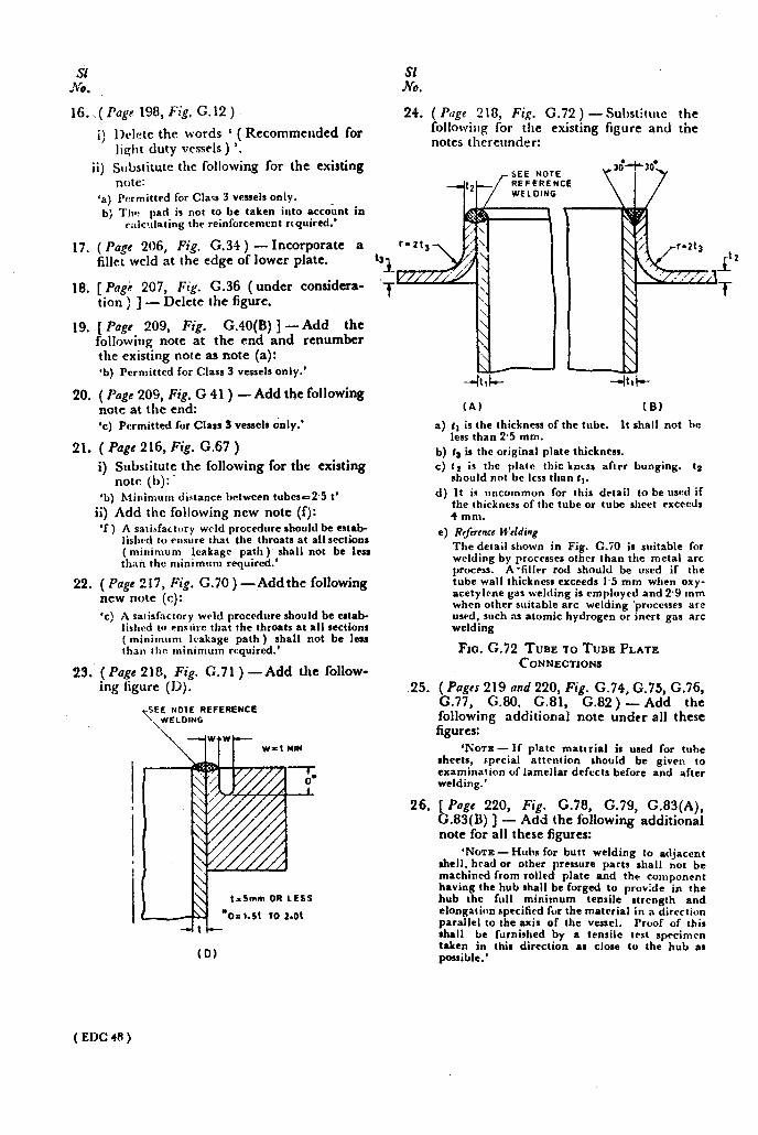
Sl ;vi .
16. ,( Png~ 198, Fig. G.12 )
i) lklete the words ‘ ( Recommended for lis+t duty vessels ) ‘.
ii) Substitute the following for the existing
17.
18.
19.
20.
21.
note: ‘a) permitted for Class 3 vessels only. b) The pad is not to be taken into account in
c:tlc~dating the reinforcement required.’
( Page 206, Fig. G.31) - Incorporate a fillet weld at the edge of lower plate.
[ PngG 207, Fig. G.36 (under considera- tion ) ] - Delete the figure.
[ Puge 209, Fig. G.40(B) ] -Add the followirtq note at the end and renumber the exiskng note as note (a): ‘b) Permitted for Class 3 vessels only.
( Page 209, Fig. G 41) - Add the following note at the end: ‘c) Permitted for Class 3 vessels only.’
( Pugc 216, Fig. G.67 )
i) Substitute the following for the existing note (b):.
‘b) Minimum dilitance between tubcse2.5 t’
ii) Add the following new note (f): ‘f ) A satisfacttlry wrld procedure should be estab-
lishcd to ensure that the throats at all sections (minimum leakage path) shall not be less than the minimum required.’
22. ( Page 2 17, Fig. G.70 ) -Add the following new note (c): ‘c) A satisfactory weld procedure should be estab-
lished to ensure that the throats at all sections (minimum Icakage path) shall not be less than the minimum required.’
23. (Pa.<e 218, Fig. G.71 ) -Add the follow- ing hgure (I~).
$1 NO.
24. ( Pup 218, Fi.c. G.72 ) -Substitute the Collorz’irlg for &e existing figure and the notes thereunder:
1 l-77 SEE NOTE
b REFFRENCE WE LOINC
‘1 -f
25.
26.
(A) (6)
a) tt is the thickness of the tube. It shall not be less than 2.5 mm.
b) I~ is the original plate thickness. c) ts is the plate thic knrss after bonging. ta
should not be less than I,. d) It is uncOmmon for this detail to beused if
the thickncrs of the tube or tube sheet exceeds 4 mm.
e) Rrfiw~cc W’tlding The detail shown in Fig. C.70 is suitable for welding by processes other than the metal arc process. A-filler rod should be used if the tube wall thickness exceeds 1.5 mm when oxy- acetylene gas welding is employed and 2.9 mm when other suitable arc welding ‘processes are used, such as atomic hydrogen or inert gas arc welding
FIG. G.52 TUBE ‘IO TUBE PLATE CONNEOTI~NS
( Pages 219 and 220, Fig. G.74, G.75, G.76, G.77, G.80, G.81, G.82) -Add the following additional note under all these figures:
‘NOTIt --If plate material is used for tube sheets, special attention should be givrn IO examination of lamellar defects before and after welding.’
[Page 220, Fig. G.78, G.79, G.83(A), G.83(B) ] - Add the following additional note for ail these figures:
‘NOTE-Hubs for butt welding to adjacent shell, hrad or other pressure parts shall not be machined from rolled plate and the component having the hub rhall be forged to provide in the hub the full minimum tensile strength and elongation specifird for the material in a direction parallel to the axis of the vessel. FrooC of this shall be furnished by a tensile trst sprcimcn taken in this direction as close to the hub as possible.’
Sl JVO.
1.
2.
3.
AMENDMENT NO. 4 MARCH 1982
TO
IS : 2825=1969 CODE FOR UNFIRED PRESSURE
Alterntions
Sl NO.
[ Sl ~‘0. 26 of Anlcndment Jo. 2 to I$ : 2825 1959 dated October 1978, ne:v clause 6.3.2(a), 4th lirx ] - Substitute ’ hole ’ fh ’ whole ‘.
(SI Xl. 2-1 of Amet:dmcnt J~O. 3 Is IS : !?823- 19159 dated Jutj~ 1979, new Fig. G.72 ) -Subs- titute ’ t? ‘j’or ‘ t3 ’ on the right hand side of the Fiq. Also under 5th line of Note ( e ) substitute ‘ 2 mm ‘for ‘ 2.9 mm ‘.
4. ( Page 5, clause following for the existing clause:
‘1.1.1 This code covers minimum construc- tion requirements for the design, fabrication, inspection, testing and certification of fusion- welded unfired pressure vessels including those intended for transportation in ferrous as well as in non-ferrous metals. ’
[ Po_ee 6, clause 1.2.5.2(fj ] -Add the following new clause after this clause:
‘g) Causes such as acceleration, decelera- tion, etc, in the case of vessels intended for transportation.’
5. [ Puge 39, clause 3.1.2.1 (c) ] -Add the foliowing new clause after this clause:
d) A typical design of jacketed portion is covered under Appendix P.
6. ( Nelu Appendix P) -Add the following new Appendix P at the end of the code:
VESSELS
1.1.1~ ). - Substitute the
‘APPENDIX P
[Che 3.12.1(d) ]
DESIGN OF JACKETED PORTION OF VESSEL
P-l. SCOPE
P-l.1 The rules in this appendix cover mini- mum requirements for the design and construc- tion of the jacketed portion of the vessel. The jacketed portion of the vessel under analysis is defined as the inner and outer walls, the closure devices and other parts within the jacket which are subject to pressure stresses.
P-l.2 For the purpose of this part jackets are assslmed to be integral pressure chambers, attached to vessels for one or more purpose such as:
.a) to heat the vessel and its contents, b) to cool the vessel and its contents, and c) to provide a sealed insulation chamber
for the vessel.
P-l.3 This appendix does not cover rules to cover all details of design and’ construction. These rules are, therefore, established to cover most common type of jackets but are not inten- ded to limit configurations to those illustrated or otherwise described therein.
P-l.4 All other parts of this code shall apply unless otherwise stated in this appendix.
Gr 1 I
P-l.5 Typical jacketed’ connections are given in Fig. G.45 to G.66 of Appendix G.
P-2. TYPE OF JACKETS AND NOTA- TION
P-2.0 Jacketing of process vessels is usually accomplished by use of one of the following main available types:
a) Conventional jackets ( see Fig. P.l and P.2 );
b) Half pipe coil jackets or limpet coil jackets ( see Fig. P.3, P.4 and P.7 );
c) Dimple jackets ( see Fig. P.6 ); and
d) Heater channels type jackets ( see Fig. P.5 ).
P-2.1 Csnventional Jacket (see Fig. P.I. and Fig. P.2 )
a) The normal configuration of conven- tional jacket is as shown in Fig. P. 1, Type A. This assures the most efficient heat transfer- to th.e maximum surface area of the vessel.
b) An often used variation of this configu- ration is made ( see Fig. P. 1, Type B ) by dividing the straight side into two or more separate jackets.
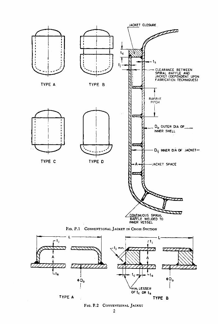
TYPE p. TYPE 5
TYPE C TYPE II
JACKET CLOSURE \
CLEARANCE BETWEEN SPIRAL BAFFLE AND JACKET (DEPENDENT UPON FABRlCATlCN TECHNIQUES)
0, OUTER DIA OF_
INNER SHELL
Dij INNER OIA OF JACKET-
JACKET SPACE
BAFFLE WELDED TO INNER VESSEL
Fxo. P.l CONVENTIONAL JACKET IN CROSS SECTION
I------L------------rl
V min. LESSER
TYPE A
Fxa. P.2 CONVENTIONAL JACKET
2
TYPE 8
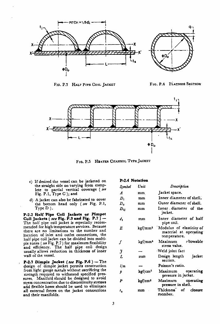
I--- PITCH = 1..Sdi _I
til ’ I
Fro. P.3 HALF PIPE COIL JACKET Fro. P.4 FLATNESS SECTION
FIG. P.5 HEATER CHANNEL TYPE JACKET
c) If desired the vessel can be jacketed on the straight side on varying from comp- lete to partial vertical coverage ( SC@ Fig. P.1, Type C ); and
d) A jacket can also be fabricated to cover the bottom head only ( see Fig. P. 1, TYPED )-
P-2.2 Ralf Pipe Coil Jackete or Pimpet Coil Jackets ( see Fig. P.3 and -Fig. P.7 ) - The half pipe coil jacket is especially recom- mended for high temperature services. Because there are no limitations to’ the number and location of inlet and outlet connections, the half pipe coil jacket can be divided into multi- ple zones ( see Fig. P.7 ) for maximum flexibility and efficiency. The half pipe coil design usually allows reduction in thickness of inner wall of the vessel.
, P-2.3 Dimple Jacket (ace Fig. P.6 ) -The design of dimple jacket permits construction from light gauge metals without sacrificing the strength rcquirtd to withstand specified pres- sures. Manifold should be designed to avoid st ess concentration due to discontinuity stresses a d d flexible hoses should be used to eliminate all external forces on the jacket connections and their manifolds.
P-2.4 Notation
Symbol
A
DI
DO
D~J
4
E
f
3 L
Um
P
P
to
3
Unit
mm. mm mm mm
mm
kgf/mmz
kgf/mmr
-
mm
-
kgf/cm2
kgf/cms
mm
DcscrijMon
Jacket space. Inner diameter of shell, Outer diameter of shell. Inner 3 diameter of the
jacket.
inner diameter of half pipe coil.
Modulus of elasticity of material at operating temperature.
Maximum allowable stress value.
-Weld joint fact Design length jacket
section. Poisson’s ratio.
Maximum operating pressure in jacket.
Maximum operating pressure in shell.
Thickness- of closure member.
T
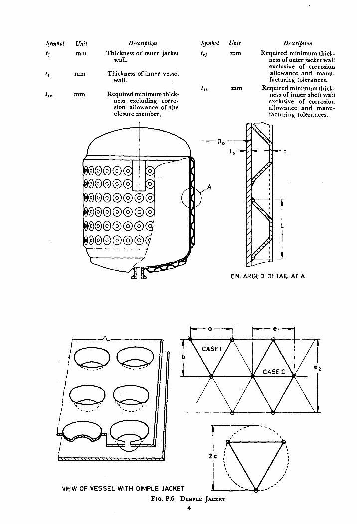
Symbol
11
t rc
Unil
mm
Descri)tion
Thickness of outer jacket wall.
Symbol
f,J
mm Thickness of inner vessel Wall.
mm Required minimum thick- ness excluding cotro- sion allowance of lthe closure member.
t r*
Unit
mm
mm
Description
Required minimum thick- ness of outer jacket wall exclusive of corrosion allowance and manu- facturing tolerances.
Required minimum thick.- ness of inner shell wall exclusive of corrosion allowance and manu- facturing tolerances.
ENLARGED DETAIL AT A
VIEW OF VESSEL-WITH DIMPLE JACKET
Fta.P.6 DIMPLEJACKET
4
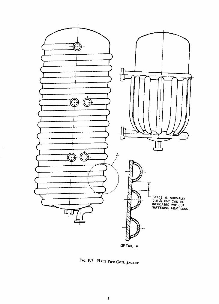
Y
T-t-r--
I I
OETAIL A
Fro. P.7 HALF PIPE COIL JACKET
P-3. DESIGN CRITERIA
P-3.1 Conventional Jacket
P-3.1.0 Design shall comply \vith the app!icable requirements of the code except \vhere otherwise provided for in the appendix.
P-3.1.1 Shell and head thickness shall be determined by the appropriate formulae given in Section 3 of this Code. In consideration of loadings particular attention to the effects of local internal and external loads and expan- sion differentials at the design temperature shall be given. Where vessel supports are atta- ched to the jacket’, consideration shall be given to the transfer of supported load of the inner vessel and contents.
P-3.1.2 The use of impingement plates or baffles at the jacket inlet connection to reduce erosion of inner wall shall be considered for media where vapours are condensed, that is, steam.
P-3.1.3 The width of jacket space shall not exceed the value given below:
A 400 xf XJ x t,* = -- - --- - 0.5 ( 1, + 1, )
P x D~J . . . . . . ( p-1 1
P-3.1.4 De&v for Jacket CloJures
P-3.1.4.1 Closures of Type 3 of Fig. P.2 ( Fig. G-55 modified ) shall be used only for Type C of Fig. P.l jacketed vessels and with further limitation that t,j does not exceed 15 mm. The required mimmum thickness for the closure bar shall be greater of the follow- ing:
tr, = 2 ( trJ ) . . . . . . (P.2 )
t,, = 0.086 6 x A x J
-T
7 . . . . . . ( P.3)
P-3.1.4:2 Closure bar and closure bar to inner vessel welds of the type shown in Fig. G.49, G.50, G.51 may be used in any of the types of the jacketed vessels shown in Fig. P. 1. The required minimum closure bar thickness shall be determined as below:
__ ~-
t,, = 0.122 47 J PDo A --’ f
. . . . . . ( P.4 )
p-3.1.5 Minimum weld size requirements are as detailed in Fig. G.45 to G.59.
P-3.2 Half Pipe Coil Jackets
P-3.2.1 The foregoing analysis is based on the following assumptions which may be suita- bly modified in case of any variations.
a) shell and halfcoil are made of the same metal,
b) the half coil is semicircular, c) both shell and coil cylinders
dered as thin in relation diameters,
are consi- to their
6
d) the coils shall be pitched not less than 14 times di, centres apart, and
NOTE - Very close spacing oi coils is not re- commended as it leadq to bad weld joint, yields very little heat transf& brncfit as the space in between the coils has an effect like fin on a finned tube.
e) half coil takes no load in comparison with the shell.
P-3.2.2 Design of Half Coil
P-3.2.2.1 A half coil is a part of torous for which stresses have been analyzed by ‘ Timoshenko ‘. It can be shown that maxi- mum hoop stress in the coil will occur at Ihe junction with the shell and is
P di j-cl = -~ 200 x t,j x 3 I.. .-a (P.5 j
and longitudinal stress is
f - P di O2 - 4UO t,j x 3 + 25u I,, x 3 -- (P.6 1
The half coil is, therefore, usually designed on a simple hoop stress basis.
P-3.2.3 Design of Shell
P-3.2.3.1 Total hoop strrss - The total hoop stress in the shell,f,t is, sum of the hoop stressf,, due to vessel pressure, and longitudi- nal stressf,z in the coil caused by coil pressure.
f-St= Toa3 + P di
IS 400 t,] x 3 + 250 t,sj x 3 . . . . . . ( p.71
P-3.2.3.2 Tootal longitudina: sfress
a) The total longitudinal stress in the wall is made of three factors:
1)
2)
3)
the longitudinal stressfsz due to ves- sel pressure, the longitudinal stress fss due to coil pressure, the bending stress fsc caused by dis- tortion of the shell at the junction with the coil.
f8* = p D1 400 x 11, x 3 . . . . . . ( P.8 1
f-*mxpt:x3 . . . . . . ( p.9 1
b) The local bending stress in the shell due to the pressure in the coil should be assessed for the case when the inter- nal pressure for the vessel is at its minimum, that is, atmospheric or vacuum. A simplified approximation based on ‘Continuous Beam Theory’ predicts a maximum bending moment, M maLx in shell of:
M max = A P d$/900 . . . . . . ( P.10 )
Also 2 AP do’
f84 = 300 t,,,r . . . . . . (P.ll)
( Negative value of /,_P = (p - p) need not be considered as this refers to high internal pressure. Bending mo- ment due to internal pressure is insigni- ficant compared with direct membrane forces which must have already been n!lowed for the hoop stress calculations.
./,r, =fsz tfss -i-f@ . . . . . . ( P.12)
cj For critical analysis ‘ Cylindrical Shell Theory ’ concept may be followed.
P-3.2.4 .iIaximum Epivalent Stress at Coil ~0
Shell Junction
The metal at the Junction of coil to shell is subject to all individual stresses present in shell and coil and maximum equivalent stress occurs at shell to coil junction. ‘This can be analyzed by ‘ Shear Strain Energy Theory ’ which adds the principie stresses acting mutually at right angles to give the equivalent stresses.
fl? = fs? + A’ S.fc1 - (fs, x f St + fSl x .Ll -i-f&t Xfcl) . . . (P. 13)
It is prudent to rl~cck that this islrithin the allowable value.
P-3.2.5 As a steam coil may be subjected to vacuum ( ifstearn is turned off j there are any possible c~v of pressure to vacuum in coit with pressure to vacuum in the shell and this gives 4 distinct limiting cases in the region of the coil. There are further 2 cases in the region where there is no coil correspon- ding to vacuum or pressure in the vessel with atmospheric pressure outside. By analyzing the stresses in details as indicated above, it is quite advisable to analyze the six conditionsto determine the worst one.
P-3.2.6 Vessel Boffoms - It is extremely diffi- cult to cut a half coil to suit a hemispherical or conical vessel bottom. Preferable methods in this regard shouid be decided between the manufacturer and designer. The recommen- ded practice is to arrange pattern of coils radially like hub spokes and rim of a wheel.
P-3.2.7 One difficulty leading to failure of the bottom end of the half coil has been traced to be ‘ Steam Hammer’ when steam is used intermittently inabatch process. The steam entering a cold vessel causes condensate to accelerate round the coils and hammer the exit branch and coil ends. For this reason the coil length should be limited to not more than three turns in series ( see Fig. P.9 ). The exit nozzle should be swept rather than right angu- lar and care taken in design of steam trap manifold.
P-3.3 Dimple Jackets
P-3.3.1 Dimple Plate Thickness
P 3.3.1.1 Case I ( see Fig. P. 8 ) - Consi- dering fixed plate with uniformly distributed load over the entire surface:
3XW hfaximum stress at edge,J,, = --. ~---- 4 x x I,12
. . . . . . ( P.14 )
Maximum deflection a; the centre
. . . . . . (P.15)
P-3.3.1.2 Cuse 2 - Dimples can be assu- med to act as ‘ stays’ in flat heads and plate thickness is checked as below, tcth for:
a) uniform spacing of staying, and
b) non-uniform spacing of the staying
P-3.3.X .3 (he rfa3.r ( sfe Fig. P.7 )
2 (a)--lh<fiwm s!,acing of
*rJ mln =CX ‘p v ( (12 -j- t”)
100 x f
. . . . . . ( P.16 )
P-3.3.1.4 Case 2 (b) - .Non-unifootm spacing of sfa_ys ( see Fig. F. 7 )
. . . . . . (P. 17)
where C = 0.40 for welded stays.
The adopted thickness ( tJ ) sidl include corrosion and manufacturing allowances, etc.
P-3.3.2 Dimple Connecting Welds -The weld attachment is made by fillet welds around holes, or if the thickness of the plate having hole is 3 mm or less and hole is 25 mm or less in diameter, the holes may be completely filled with weld metal. The allowable load on weld shall equal the product of the thickness of plate having the hole, t~he circumference or perime- ter of hole, the allowable stress value in tension of the material being welded and joint efficiency of 55%. The connecting welds shall be checked for shear and tear failures.
P-4. CONSIDERATIONS OF STIFFENING EFFECT OF JACKET ELEMENTS ( see Fig. P.2 to P.6 )
P-4.1 Calculations for Elastic Buckling
IUaximum working pressure, P =
. . . . . . ( P.18 )
7
and ‘ n ’ should be chosen as a whole number
[ n&l n > 2 )---- ‘LL 1 in such a way that p is at its
lowest value. ‘ n’ is then the number of dents which may appear on the surface in the event of failure.
P-4.2 Calculation for Plastic Deformation
P-4.2.1 Case I - \t’hen 2 < 5, the maxi-
mum permissible working pressure is given by:
P,=200xf x g x 0
1
1.5c (
0.2 D, 1 _ L-- .*.
1+ -- >
( P.19 )
10~ f,,jD,
where u = out of roundness factor.
a) For ovality cr = 2 X Di max - D1 min
7 Di max f D1 nun
x 100
b) For flatness C = g x q 0 x 100 ( see Fig. P.4 ).
P-4.2.2 Case 2 -When % > 5
p = Greater of zDl*’ or 0
300 f x t,s2* L*
. . . . . . ( P.20 )
P-4.2.3 In vacuum vessels the stiffening effect of the jacket elements ( half pipe coils, heater channels, etc ) may be taken into consi- deration in calculating the whole shell. For elastic buckling analysis the permissible pres- sure will then be greater, in proportion to the moment of iner’tia ( taken about the axis through the appropriate centre of gravity X-X, or X’-X’ ) and for plastic deformation analysis the permissible pressure will be grea- ter in proportion to the cross-sectional areas with and without the jacketing elements.
*This formula is particularly applicable when distance between stiffeners is small.
8
P-5. FABRICATION
P-5.1 Fabrication of vessels shall be in accor- dance with applicable parts of the code. . . P-5.2 This part covers fabrication of jacketed vessels by welding. Other methods of fabri- cation are permitted provided the requirements of applicable parts of this section are met.
P-5.3 Where only the inner vessel is subject to lethal service the requirements regarding radio- graphy, post weld heat treatment shall apply only to the welds in the inner vessel and those welds attaching the jacket to the inner vessel need not be radiographed and may be fillet- welded. Post weld heat treatment shall be as required in 6.12 of the code.
P-5.4 Proper testing for pinholes in the welds is mandatory.
P-5.5 Any radial welds in closure members shall be butt-welded joints penetrating through the full thickness of the member and shall be ground flush where attachment welds are to be made.
P-6. APPLICATIONS
P-6.1 Conventional jackets are used where the internal pressure of the vessel is more than twice the jacket pressure, the jacket pressure being limited to 7 kgf/cms.
P-6.2 Dimple jackets and half-pipecoil jackets are used for vessels beyond 2ms capacity and where the jacket pressure is the controlling -factor (that is, the vessel internal pressure is less than 1.67 times the jacket pressure ) in determining the vessel wall thickness. These are used for high pressure (that is, dimple jackets up to 21 kgf,‘cms and half pipe coil jackets up to 52.5 kgf/cms ) and high tempera- ture applications.
NOTE -For high temperature applications thermal expansion differentials should be consi- dered between the metals used in the vessel and the jacket, and difference in thicknesses between the vessel and the jacket walls, and for temperatures beyond 300°C the jacket be fabricated from a metal having the same coefficient of expansion as that used for the inner vessel.
Printed at Kay Kay Printers. Delhi ’
AMENDMENT NO. 5 OCTOBER 1988
TO
IS : 2825 - 1969 CODE FOR UNFIRED PRESSURl$ VESSELS
(Page 9, clause 1.3.1.3, line 4 ) - Add the words ‘or gas’ after the word ‘vapour’.
( Page 9, clause 1.3.1.3 )
a) Line 4 - Add the words ‘or gas’ after the word ‘vapour’.
b) Line 5 - Delete the word ‘design’.
NOTE - Hydrostatic pressure means pressure due to liquid head only.
[ Page 14, Tables 3.1, 3.2, 3.3 and 3.4 ( see also Amendment Jvo. 2, Sl .No. 11 ) ] - Retain the tables with all the existing matter.
[ Page 2 1, clauses 3.4.6.1 (a) and 3.4.6.2(a), line 4 ( see also Amendment Jvo. 2, Sl .No. 12 and 13 ) ] - Suhstitute ‘3.3.3.t’for ‘3.3.3.3’.
[ Page 35, clause 3.8.7.1(b), line 2 ] - Substi- tute ‘P2 ( 50 mm nominal bore )‘for ‘P 14 size’.
( Page 36, clause 3.9.4, last line ) - Substitute ‘P2 ( 50 mm nominal bore )‘for ‘size P 13’.
( Page 65, cl&se 6.2.5,Jirst para ) - Substitute the following for the existing para:
‘Any person who wishes to qualify for welder’s performance test under this code, shall not be below the age of 18 years and shall have adequate experience or training.’
( Page 71, clause 6.4.10, last sentence > - Subs+ tute the following for the existing sentence:
“If the forming or bending operation takes place in hot condition, no subsequent heat treat- ment is required, provided during the last opera- tion, it is uniformly heated to a temperature within the normalizing range.’
[ Page 71, clause 6.4.11, Jirst sentence ( see also Amendment No. 3, SL Jvo. 6 ) ] - Substitute the following for the existing sentence:
‘6.4.11 Plates Welded Prior to Formin,g - Seams in plates may be welded prior to forming provided they are examined radiographically throughout the entire length after forming. In the case of class 1 and 2 vessels, the seams shall also be inspected by magnetic crack detection or dye- penetrants.’
( Page 71, clause 6.5.1, last s’cntence ) - Substi- tute the following matter for the existing sentence:
‘Tack welds shall either bet removed completely when they have served their purpose or their stopping and starting ends shall be properly pre- pared by grinding or other suitable means so that they may be satisfactorily incorporated into the final weld. Tack welds shall be made by qualified procedures and welders, and shall be examined visually for defects and, if found to be defective, shall be removed.’
[ Page 75, clause 6.12.2(a) ] - Substitute the following for the existing matter:
‘a) intended for containing lethal* material;’
[ iage 75, clause 6.12.2(g) ] -Add the follow- ing new items after 6.12.2(g).
‘h) intended‘ for transport of flammable or toxic material; and
j) when required by the statutory authority.’
( Page 76, Table 6.3 ):
a) Material Group 2a - Substitute ‘ Sum “f alloying elements, that is, Cr, MO and V 0’80 Max
for 6 Residual or other elements 0.80 Max ‘.
b) Renumber material group ‘2a’ as ‘2’. c) Renumber material group ‘2b“as 63’. d) Delete the present material group ‘3’.
[ Page 77, clause 6.12.3.1(b), line 6 ] - Subs-
titute ( 2*5d/rt’for c 5V/rt ‘.
( Page 96, clause 8.4.2.2, para 3, jirst sentence ) - Substitute the following for the existing sentence:
‘The vessel shall be maintained at the specified test pressure for a sufficient length of time to stabilize the pressure but in no case less than 10 minutes. A thorough examination of the vessels shall be carried out after lowering the pre- ssure to 80 percent of the test pressure.’
( Page 96, clause 8.4.2.2, para 3, second and third sentences ) - Delete.
( Page 96, clause 8.5.1 )-Substitute the follow- ing tbr the existing clause:
‘8.5.1 Two production test plates representing- approximately 15 metres of weld or five shell courses, whichever is higher, shall be provided with longitudinal seams for every weld procedure applicable to the vessels or series of vessels made to the same drawing/specification. Vessels having more than 5 shell courses shall be provided with an additional production test plate representing the next 15 metres of welding or part thereof. No test plate need be provided for circumferential seams except in cases where a vessel has circum- ferential seams only or the welding process, procedure or technique is substantially different, in which case two test plates are to be provided.
8.5.1(a) For low temperature vessels, in addi- tion to the test coupon plates mentioned in 8.5.1, each other shell course shall ‘also be provided with a coupon plate sufficiently long for testing two sets of impact test ( one for weld metal and one for heat affected zone ). One set of tests shall be conducted to cover 5 seams.
*See 1.3.1.1(a) regarding ‘lethal’.
clarification of the word
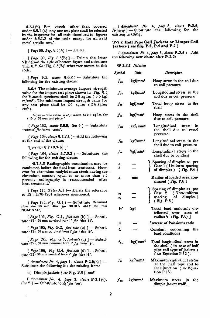
8.5.1(b) I?& vessels other than covered under 8.5.1 (a), any one test plate shall be selected by the inspector for all tests described in figum under 8.5.1.2 of the code except for all weld metal tensile test.’
[ Page 99, Fig. 8.5(A) ] - Relete.
[ Page 99, .Fig. 8.5(B) ] - Delete the letter ‘(B)’ froni the title of bottom figure and substitute ‘Fig. 8.5’fir ‘Fig. 8.5(B)’ wherever occurs in this code.
( Page 102, clause 8.6.2 ) - Substitute the following for the existing clause:
‘8.6.2 The minimum average impact strength value for the impact test piece shown in Fig. 8.5 for V-notch specimen shall be 2.8 kgf.m ( 3.5 kgf
1 /cm*). The minimum impact strength value for
~1 )test piece shall be 2.1 kgf.m ( 2 6 kgfm/
NOTE - The value is equivalent to 28 kgf.m for a 10 X 10 mm test piece.’
( Page 103, clause 8.6.8, line 4 ) - Substitute ‘retests’for ‘new tests’.
( Page 104, clause 8.7.2.1 )-Add the following at the end of the clause:
‘[ see also 8.7.10.3(b) 1’
( Page 104, clawe 8.7.3.3 ) - Substitute the following for the existing clause:
‘8.7.3.3 Radiographic examination may be conducted before the final heat treatment. How- ever for chromium molybdenum steels having the chromium content equal to or more than 1.5 percent radiography is recommended after heat treatment.’
( Page 1.15, Table A. 1 )- Delete the reference to IS : 1570-1961 wherever mentioned.
( Page 195, Fig. G.1 ) - Substitute ‘Nominal pipe size 50 mm MUX’ for ‘BORE MAX 100 mm NOMINAL’.
[ Page 195, Fig. G.l, foot-note (b) ] -- Substi- tute CP2 ( 50 mm nominal bore )’ fey csize 1)‘.
[ Page 195, Fig. G.2, foot-note (b) J - Substi- tute ‘P2 ( 50 mm nominal bore )‘foy 6 size 14’.
[ Page 195, Fig. G.3, foot-note (c) ] - Substi- tute sP2 ( 50 mm nominal bore )‘fof ‘size 1)‘.
( Page 196, Fig. G.4, foot-note (d) 1 - Substi- tute ‘P2 ( 50 mm nominal bore )’ for <size 1)‘.
[ Amendment No. 4, page 1, clause P-2.8(4 ] - Substitute the following for the existing item:
‘c) Dimple jackets ( s8e Fig. P.6 ); and’
[ Amendment 4%. 4, page 3, clause P-2.1 (c), line 2 ] - Substitute ‘only’for ‘on’.
( Amendment No. 4, page 3, clause P-2.2, Heading ) - Substitute the following for the existing heading:
‘P-2.2 Half Pipe Coil Jackets or Limpet Coil Jackets _( _sce Fig. P.3, P.4 and P.7 )’
( &nendment No. 4, page 3, clause P-2.2 )-Add the following new clause after P-2.2:
‘P-2.2.1 Notation
Symbol Unit
fo1 kgf/mm*
Description
fos
fat
fs1
Isa
fse
far
a b
el es
W
m
C
fSL
fe
f ed
kgf/mm’
kgf/mm’
kgf/mms
kgf/mm’
kgf/mms
kgf/mms
Hoop stress in the coil due to coil pressure
Longitudinal stress in the coil due to coil pressure
Total hoop stress in the shell
Hoop stress in the shell due to coil pressure
Longitudinal stress in the shell due to vessel pressure
Longitudinal stress in the shell due to coil pressure
Longitudinal stress in the shell due to bending
- 1 Spacing of dimples as per
- t Case 1 ( Uniform spacing J of dimples ) ( Fig. P.6 )
mm Radius of loaded area con- sidered ( Fig. P.6 )
S acing of dimples as per - 1L e 2 ( Non-uniform
I
spacing of dimples ) ( Fig. P.6 )
kgf Total load uniformly dis- tributed over area of radius ‘c’ (Fig. P.6) ]
- Ipverse of Poission’s ratio
- Constant concerning the load conditions
kgf/mm* Total longitudinal stress in the shell ( in case of half pipe coil type of jackets ) ( see Equation P.12 ) .
kgf/mms Maximum equivalent stress at the half pipe coil to shell junction ( see Equa- tion P.13)
kgf/mms Maximum stress in the dimple jacket wall’.
2
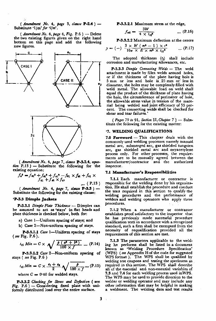
( &ndm& h%. 4, page 3, clauss P-2.4 ) - Substitute ‘l/m’for ‘l/m’.
( Amendment No. 4, flags 4, Fig. P.6 ) - Delete the two existing figures given ori the right hand bottom on this page and add the following new figures.
( Amendment No. 4, page 7, clause P-3.2.4;squa- rim P.13 ) - Substitute the following for the existing equation:
f*' =f8l'+frt'+fcl* --x31 xfa +fi1 x fc1 +fat XfOI
. . . ( P.13 )
( Amendment &ix 4, PagG 7, clau~s P-3.3 ) -- Substitute the following for the existing clause:
‘P-3.3 Dimple Jackets
P-3.3.1 DimprC Plate Thickness - Dimples can be assumed to act as ‘stays’ in flat heads and plate thickness is checked below, both for:
a) Case l-Uniform spacing of stays; and
b) Case P-Non-uniform spacing of stays.
P-3.3.1.1 Care I-Uniform spacing of stays (see Fig. P.6).
t,l Min = C x “16”6 xs”‘) ... (P.14)
3
P-3.3.1.2 Cart 2-Non-uniform spacing of stays ( see Fig. P-6 )
trj Min = C x - 61 + 4~ P
2 i@Ey* (P.15)
where C = 0.40 for welded stays.
P-3.3.2 Checking for Stress and ?&&ion ( crea Fig. P.6 ) - Considering fixed platl with uni- formly distributed load over the entire surface.
P-3.3.2.1 Maximum stress at’ the edge,
f 3w
cd - 4 x t*j’
P-3.3.2.2 Maximum deflection at the centre
The adopted thickness (tj) shall include corrosion and manufacturing allowances, etc.
P-3.3.3 Dimple Connecting Welds - The weld attachment is made by fillet welds around holes, or if the thickness of the plate having hole is 5 mm or less and hole is,25 mm ori less in diameter, the holes may be completely ded with weld metal. The allowable load on weld shall equal the product of the thickness of plate having the hole, the circumference of perimeter of hole, the allowable stress value in tension of the mate- rial being welded and joint efficiency sf 55 per- cent. The connecting welds shall be checked for shear and tear failures.’
( Pages 79 to 91, Section II, Chapter 7’) - Subs- titute the following for the existing matter:
‘7. WELDING QUALIFICATIOiVS
7.0 Foreword - This chapter deals with the commonly used welding processes namely manual metal arc, submerged arc, gas shielded tungsten arc, gas shielded metal arc and oxyacetylene process only. For other process&, the require- ments are to be mutually agreed between the manufacturer/contractor and the authorized inspector.
7.1 Manufacturer’s Responsibilities
7.1.1 Each manufacturer or contractor is responsible for the welding done by ‘his organiza- tion. He shall establish the procedure and conduct the tests required in this section to qualify the welding procedures and the performance of welders and welding operators who apply these procedures.
7.1.2 When a manufacturer or contractor establishes proof satisfactory to the inspector that he has previous1
s/y made successful procedure
qualification te s in accordance with a recognized standard, such a firm shall be exempted from the necessity of requalification provided all the requirements of this section are met.
7.1.3 The parameters applicable to the weld- ing he performs shall be listed in a document known as ‘Welding Procedure Specification’ (WPS) ( see Appendix H of the code for suggested WPS format ). The WPS shall be qualified by welding test coupons and testing the specimens as required in this section. The WPS shall describe all of the essential and non-essential variables of 7.3 and 7.4 for each welding process used inWPS. The WPS may be used to provide direction to the welder or welding operator and may include any other information that may be helpful in making a weldment. The welding. data and test results
shall be recorded in a document known as ‘Procedure Qualification Record’ ( PQR ) ( see Appendix H for suggested PQR format ). The PQR is a record of what happened during a particular welding test and changes to. PQR are not permitted unless requalified by the manufac- turer or contractor.
7.1.4 Test plate is to be welded by the manu- facturer or contractor and he may subcontract testing.
7.2 Test Positions
7.2.1 All test welds for welding procedure qualification shall be carried out as groove welds in any of the positions described in the following paragraphs, except that the angular deviation shall be within f 15 degree from the specified horizontal and vertical planes and &5 degree from the specified inclined plane,
7.2.2 The following are the basic positions for welding ( see Fig. 7.1 ).
7.2.2.1 Flat position - Plate in horizontal plane with the weld metal deposited from above. Pipe with its axis horizontal and rolled during welding so that the weld metal is deposited from above ( see Fig. 7.1 A-l and Fig. 7.1 A-2 ).
7.2.2.2 Horizontal joposition - Plate in vertical plane with the axis of weld horizontal:
Pipe with its axis vertical and the axis of weld in horizontal plane:
Pipe shall not be rotated during welding ( see Fig. 7.3 B-l and Fig, 7.1 B-2 ).
7.2.2.3 Vertical position - Plate in vertical plane with the axis of weld vertical ( see Fig. 7.1C ).
X2.2.4 Overhead position - Plate in horizon- tal position with the weld metal deposited from underneath ( see Fig. 7.1D ).
7.2.2.5 Multt$fe josition horizontal - Pipe with its axis horizontal and the welding groove in a vertical plane. Welding shall be done without rotating the pipe so that weld metal is deposited in muhipla position ( see Fig. 7.1E ) .
7.2.2.6 Multjle postbon inclined - Pipe with its axis inclined at 45” to horizontal. Weld- ing shall be done without rotating the pipe ( see Fig. 7.1F ).
7.3 Essential Variables - Procedure qualifica- tion is required whenever there is a change in the welding condition which will affect the properties of the weldment, namely, change in the material group, welding process, filler metal, preheat or postweld heat, treatment. Retesting is also required beyond the range qualified and for any change in position, For low temperature vessels.
7.3.1 Base Metal - Procedure qualification required in the following’ cases.
7.3.1.1 A change from a base metal listed under one metal group given in Table 6.3 of the code to the metal listed under another with the same metal group, the procedure qualified on metal with certain minimum tensile strength does not’qualify for welding metal with higher specified tensile strength.
7.3J.2 When a joint is made between two base metals that have different material groups even though qualification testing have been made for each of the two base metals welded to itself.
7.3.1.3 When the thickness of base metal is beyond the range qualified in accordance with Table 7.1 and 7.3.1.5 and 7.3.6.3.
7.3.1.4 Any major change in weld prepara- tion details for low temperature ,operation and single-sided j oint.
7.3.1.5 For the short circuiting transfer made of the gas shielded arc process when the thickness exceeds 1.1 times the thickness of test coupon.
7.3.2 Welding Process -For each welding pro- cess a new WPS is required and each process shall be qualified. This may be qualified either separately or in combination with other processes. For multi-processes, the qualified thickness of each process shall not be additive in determining the thickness qualified.
7.3.3 Fillm Metal - The filler metal classifica- tion to be used on the production weld should be same as the one used for procedure qualification. Any appreciable variation in the filler metal classificatjon from the one used for the procedure wiI1 rec@re requalification. In case of single welded joint, a change of more than one-third in the diameter of electrode for root run of manual metal arc welding requires requalification for low temperature operation.
7.3.4 Position ( Low Tm~fa~e Vwscls only > - The change of position is an essential varia- ble for low temperature vessels only and requires requalification. However, if the position qualified is vertical up, it qualifies for other positions also. In vertical position, a change from stringer bead to weave bead calls for requalification.
7.3.5 Preheat - The miuimum preheat tempe- rature shall be specified in WPS. A decrease of more than 50 degree Celsius and an increase of more than 100 degree Celsius for low temperature and stainless steel jobs from the minimum speti- fied shah require requalification,
4
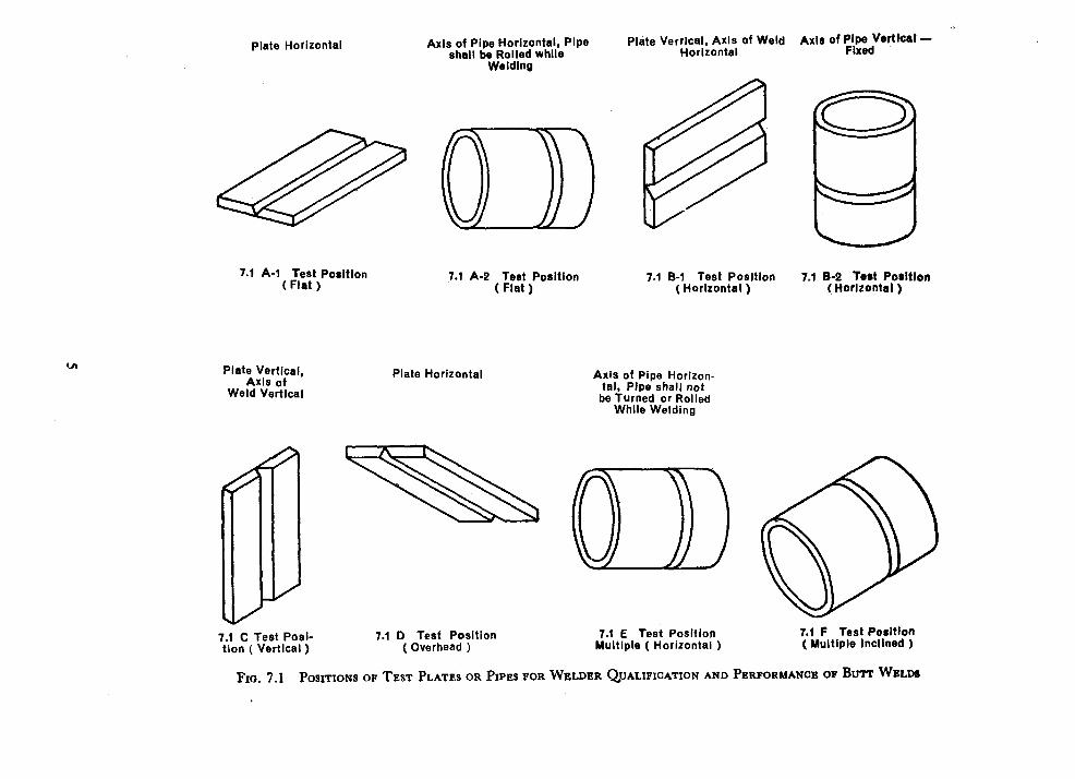
Plate Horizontal Axis of Pipe Horizontal, Pipe shall be Rolled while
welding
Plate Verrical, Axis of Weld Horizontal
* Axin of p:pXdVwtlcal -
7.1 A-l Test Position ( Flat )
7.1 A-2 Test Position ( Flat )
7.1 B-1 Test Position (Horizontal )
7.1 B-2 Test Poritlon (Horlzontal )
Plate Vertical, Axis of
Weld Vertical
7.1 C Test Posi- 7.1 0 Test Position 7.1 E Test Position 7.1 F Test Posltlon
tion ( Vertical ) ( Overhead ) Multiple ( Horizontal ) (Multiple Inclined )
)?~a. 7.1 POS~IONS OF TEST PLATES OR PIPES FOR WELDER QUALIFICATION AND PERFORMANCE OF Bv~ WELDS
Plate Horizontal Axis of Pipe Horizon- tal, Pipe shall not
be Turned or RolleU While Welding
M
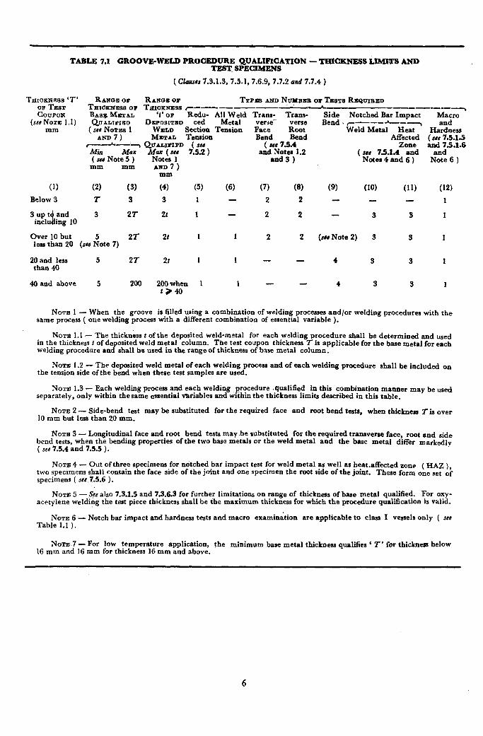
TABLE 7.1 GROOVE-WELD PROCEDURE QUALD’ICATION - lTiICKNESS LIMITS AND TEST_ SPECIMENS
(Classes 7.3.1.3, 7.5.1, 7.6.9, 7.7.2 end 7.7.4 )
Tatcc~~“~‘2-’ RANGE OF R ANOU OP TYPES AND NTJMBXB OF TESTY REQTJIBED
COUPON THIOIKXESE or TIXI;F~ I--------- P-L ----w-m-- BASK MBTAL Redu- All Weld Tram- Trans-
(sea NOTE 1 .I) QU~LIBIED DEPOSLTUD ted Metal verle- verse mm ( see NOTES 1 WELD Section Tension Face Root
AND 7) METAL Tension Bend Bend C--A-~ QUALIPIPD ( su ( III 73.4 Mk Max MNz.vsy 7.53 ) and Notes 1.2 ( sed Note 5 ) and3)
AND 7 ) mm
(4) (5) (6) (7) (8)
3 1 - 2 2
2t 1 - 2 2
2t 1 1 2 2
2r 1 1 - -
Side Notched Bar Impact Macro ’ Bend .T .---_---7 and
Weld Metal Heat Hardness Affected (~86 7.5.1.5
Zone and 7.5.1.6 ( sad 7.5.1.4 and and
Notes 4 and 6 ) Note 6 ) mm mm
(1) (2) (3)
Below 3 I 3
3upt % and 3 21 inclu ing 10
Over 10 but 5 2T less than 20 (see Note 7)
20 and less 5 21 than 40
40 and above 5 200 2OOwhen 1 1 - - t,40
(9) (10) (11) (12)
1
3 3 1
(NI Note 2) 3 3 1
4 3 3 1
4 3 3 1
NOTE 1 - When the groove is filled using a combination of welding processes and/or welding procedures with the same process ( one welding process with a different combination of essential variable ).
NOTE 1.1 - The thickness t of the deposited weld-metal for each welding procedure shall be determined and used in the thickness t of deposited weld metal column. The test coupon thickness T is applicable for the base metal for each welding procedure and shall be used in the range of thickness Df base metal column.
NOTE 1.2 - The deposited weld metal of each welding process and of each welding procedure rhall be included on the tension side ofthe bend when these test samples are used.
NOTE 1.3 - Each welding process and each welding procedure qualified in this combination manner may be used separately, only within thesame essential ariables and within the thickness limits described in this table.
NOTE 2 - Side-bend test may be substituted for the required face and root bend tests, when thickness Tis over 10 mm but less than 20 mm.
NOTB 3 - Longitudinal face and root bend tests may be substituted for the required transverse face, root and side bend tests, when the bending properties of the two base metals or the weld metal and the base metal differ markedly ( see 7.5.4 and 7.5.5 ) .
NOTE 4 - Out of three specimens for notched bar impact test for weld metal as well as heat.affected aone two specimens shall contain the face side of the joint and one specimen the root side of the joint.
( HAE )
specimens ( see 7.5.6 ). These form one set ok
NOTE 5 - .S~C also 7.3.1.5 and 7.3.6.3 for further limitations on range of thickness of base metal qualified. For oxy- acetylene welding the test piece thickness shall be the maximum thickness for which the procedure qualification is valid.
NOTE 6 - Notch bar impact and hardness tests and macro examination are applicable to class I vessels only ( se8 Table 1.1 ).
NOTE 7 - For low temperature application, 16 mm and 16 mm for thickness 16 mm and above.
the minimum base metal thickoess qualifiea ‘ I’ for thickness below
6
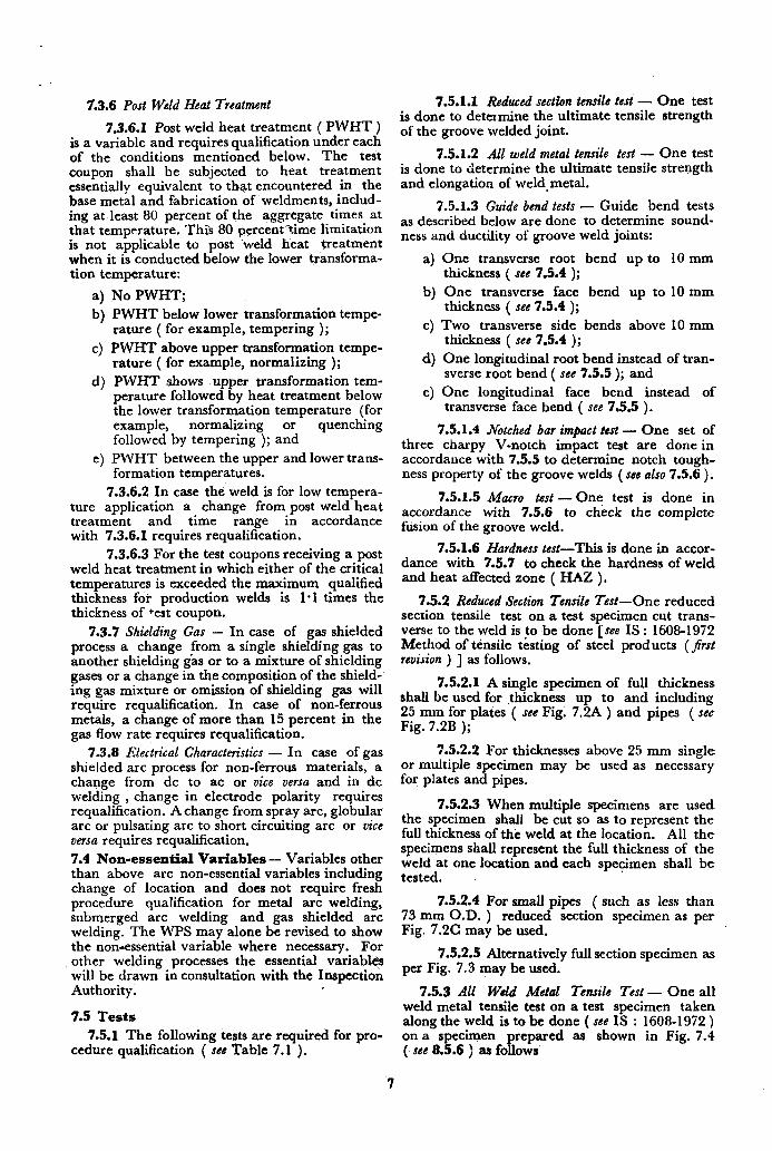
7.3.6 Post Weld Heat Treatment
7.3.6.1 Post weld heat treatment ( PWHT ) is a variable and requires qualification under each of the conditions mentioned below. The test coupon shall be subjected to heat treatment essentially equivalent to that encountered in the base metal and fabrication of weldments, includ- ing at least 80 percent of the aggregate times at that temperature. This 80 percent-time limitation is not applicable to post ‘weld heat treatment when it is conducted below the lower transforma- tion temperature:
a) 9
4
4
e)
No PWHT;
PWHT below lower transformation tempe- rature ( for example, tempering );
PWHT above upper transformation tempe- rature ( for example, normalizing );
PWHT shows upper transformation tem- perature followed by heat treatment below the lower transformation temperature (for example, normalizing or quenching followed by tempering ); and
PWHT between the upper and lower trans- formation temperatures.
7.3.6.2 In case the weld is for low tempera- ture application a change from post weld heat treatment and time range in accordance with 7.3.6.1 requires requalification.
7.3.6.3 For the test coupons receiving a post weld heat treatment in which either of the critical temperatures is exceeded the maximum qualified thickness for production welds is 1 *l times the thickness of test coupon.
7.3.7 Shielding Gas - In case of gas shielded process a change from a single shielding gas to another shielding gas or to a mixture of shielding gases or a change in the composition of the shield- ing gas mixture or omission of shielding gas will require requalification. In case of non-ferrous metals, a change of more than 15 percent in the gas flow rate requires requalification.
7.3.8 Electrical Characteristics - In case of gas shielded arc process for non-ferrous materials, a change from dc to ac or vice versa and in dc welding , change in electrode polarity requires requalification. A change from spray arc, globular arc or pulsating arc to short circuiting arc or vice versa requires requalification.
7.4 Non-essential Variables - Variables other than above arc non-essential variables including change of location and does not require fresh procedure qualification for metal arc welding, submerged arc welding and gas shielded arc welding. The WPS may alone be revised to show the non-essential variable where necessary. For other welding processes the essential variables will be drawn in consultation with the Inspection Authority.
7.5 Tests
7.5.1 The following tests are required for pro- cedure qualification ( see Table 7.1 ).
7.5.1.1 Reduced section tensile tesi - One test is done to determine the ultimate tensile strength of the groove welded joint.
7.5.1.2 All weld metal tensile test - One test is done to determine the ultimate tensile strength and elongation of weld.metal.
7.5.1.3 Guide bend tests - Guide bend tests as described below are done to determine sound- ness and ductility of groove weld joints:
4
4
4
4
4
One transverse root bend up to 10 mm thickness ( see 7.5.4 );
One transverse face bend up to 10 mm thickness ( see 7.5.4 );
Two transverse side bends above 10 mm thickness ( see 7.5.4 );
One longitudinal root bend instead of tran- sverse root bend ( see 7.5.5 ); and
One longitudinal face bend instead of transverse face bend ( see 7.5.5 ).
7.5.1.4 titched bar impact test - One set of three charpy V-notch impact test are done in accordance with 7.5.5 to determine notch tough- ness property of the groove welds (see also 7.5.6 ).
7.5.1.5 Macro test - One test is done in accordance with 7.5.6 to check the complete fusion of the groove weld.
7.5.1.6 Hardness test-This is done in accor- dance with 7.5.7 to check the hardness of weld and heat affected zone ( HAZ ),
7.5.2 Reduced Section Tensile Test-One reduced section tensile test on a test specimen cut trans- verse to the weld is to be done [see IS : 1608-1972 Method of tensile testing of steel products (&t revision ) ] as follows.
7.5.2.1 A single specimen of full thickness shall be used for thickness up to and including 25 mm for plates ( see Fig. 7.2A ) and pipes ( se6 Fig. 7.2B );
7.5.2.2 For thicknesses above 25 mm single or multiple specimen may be used as necessary for plates and pipes.
7.5.2.3 When multiple specimens are used the specimen shall be cut so as to represent the full thickness of the weld at the location. All the specimens shall represent the full thickness of the weld at one location and each specimen shall be tested.
7.5.2.4 For small pipes ( such as less than 73 mm O.D. ) reduced section specimen as per Fig. 7.2C may be used.
7.5.2.5 Alternatively full section specimen as per Fig. 7.3 may be used.
7.5.3 All Weld Metal Tensile Test - One all weld metal tensile test on a test specimen taken along the weld is to be done ( see IS : 1608-1972 ) on a specimen prepared as shown in Fig. 7.4 (. see 8.5.6 ) as follows
7
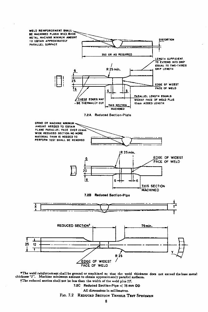
WELD RLINFORCEME~T qHAu
GE MACHiNE FLUSH WILH. GA
METAL. MAtHINE MINIMUM ANGUNT
TO OBTAIN APPROXIMATELY DISTORtlOW
PARALLEL SURFACE I
t
260 OR AS REOUIREO
LENGTH SUFFICIENT~
I EQUAL TO TWO-THIRCS
I? 25 min.
I - 1 :o T
I - i 25
/ /’ FACE Ot WELD
L- e-k PARALLEL LENGTM EGUALS
THESE EDGES MAY r- WIDEST FACE OF WELD PLUS
. BE THERMALLY CUT -THIS SECTION _
12rqn ADDED LENGTH
’ - MACHINED ’
7.2A Reduced Section-Plate
GRIND OR MACHINE MINIMUM
MATERIAL THAN IS NEEDED TO
PERFORM TEST SHALL GE REMOVED
r--+qx7--- -_-_-.
B _’
6
r _ THIS SECTION
’ MACHINED
7.28 Reduced Section-Pipe
---we_ __ - --. __-_- I 4 \ I 1’
__ - ----_ _- t
REDUCED SECTION’ i= 75min. 1 1 ,r
f 1 I 25 12 --- _--p-.-_
1 f
R 25 I
/EDGE 0F WIDEST / FACE OF WELD
*The weld reinforcement shall be ground or machined so that the weld thicknesr does not exceed the base metal thickness ‘I’. Machine minimum amount to obtain approximately parallel surfaces.
tThe reduced section shall not be less than the width of the weld plub 2X
7.2C Reduced Section-Pipe < 76 mm OD
All dimensions in millimetres.
FICL 7.2 REDUCED SECTION TENSILE TEST SPECIMEN
8
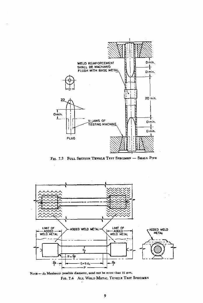
WELD REINFORCEMENT SHALL BE MACHINED FLUSH WITH BASE MET
TESTING MACH
PLUG
FIG. 7.3 FULL SECTION TENSILE TEST SPECIMEN - SMALL PIPE
,I.---
NOTE - do Maximum poaaible diameter, need not be more than 16 mm.
Fro. 7.4 ALL WELD METAL TENSILE TEST SPECIMEN I
9
7.5.3.1 The diameter of the test specimen is the maximum possible diameter and this need not be more than 16 mm.
7.5.3.2 The test should include tensile strength, yield strength and elongation.
7.5.3.3 For design temperature above 100 degree Celsius the test shall include elevated tem- perature, testing.
7.5.3.4 In case of multiple process or multi- ple procedure the specimen are to be prepared to represent each process/procedure. The location and size of specimen are selected in consultation with the Inspection Authority.
7.5.3.5 For pipe instead of one all weld metal tensile test, one extra transverse tensile test is to be done ( see Fig. 7.9 ).
7.5.4 Transverse Bend Test - Two transverse root bend tests and two face bend tests are to be done on test specimens cut transverse to the weld ( see 8.5.9 ). The diameter of former and distance between supports shall be as given in Table 8.2.
7.5.4.1 The specimens are bent such a way that the root surface becomes convex surface in one set and the face surface becomes convex surface in another set ( see Fig. 7.5A and Fig. 7.5B ).
7.5.4.2 When the thickness of plate exceeds 10 mm, face bend and root bend tests are to be substituted by two side bend tests ( see Fig. 7.5C ).
7.5.5 Longitudinal Bend Test -Transverse bend tests may be substituted with one face bend and one root longitudinal bend test ( see Fig. 7.6 ), when the weld metal and the parent metal differ markedly in bending properties either between dissimilar parent metals or weld metal and parent metal. The tests shall be done as per transverse bend test procedure ( see 7.5.4 ).
7.5.6 h’otched Bar Impact Test - One test of three V-notch impact test specimens transverse to the weld is to be tested as per 8.5.8 of the code. In case of welds for low temperature application, three more impact test specimens shall be taken from the heat affected zone and tested.
7.5.7 Macro Test - One macro test on a speci- men cut transverse to the weld is to be done to determine the complete fusion and free from cracks, as per the code ( see 8.5.11 ) .
7.5.8 Hardness Test - Hardness test is to be done on the macro test specimen along the cross section of the weld and the heat affected zone. The hardness shall be assessed by a HV indentor of not more than 30 kgf load;
7.5.9 Preparation .of Test Coupon - The base metal and filler metal shall be as per 7.7.
7.5.18 Order of Removal of Test Specimens - The test specimens are removed from the test coupon as detailed below:
’ a) Where transverse bend tests are required,
the test specimens are removed as shown in Fig. 7.7.
b) Where longitudinal bend tests are required, the test specimens are removed as shown in Fig. 7.8.
c) Where test is done on a pipe, the test specimens are removed as shown in Fig. 7.9.
7.6 Acceptance Criteria- In order to pass the test, specimens shall have the following minimum requirements.
7.6.1 Transverse Tensile Test
7.6.1.1 Specified minimum tensile and yield strength of base metal.
7.6.1.2 In case of two different metals, specified minimum strength of the weaker of the two.
7.6.1.3 If the specimen breaks outside the fusion line, the test shall be accepted as meeting the requirement provided the strength is more than 95 percent of the minimum tensile strength of the base metal.
7.6.2 All Weld Metal Test
7.6.2.1 The tensile strength and/or yield strength shall not be less than the corresponding specified minimum values for the parent metal.
7.6.2.2 The elongation shall not be less than 80 percent of the minimum elongation specified for the base metal corrected for the gauge length if different from 5 do.
7.6.2.3 For elevated temperature test, the values shall not be less than corresponding values for the base metal at the appropriate temperature.
7.6.3 Bend Tests
7.6.3.1 The weld and heat affected zone of a transverse bend specimen shall be completely within the bent portion of the specimen after testing.
7.6.3.2 The specimen shall have no open defect in the weld or heat affected zone exceeding 3 mm measured in any direction on the convex surface of the specimen.
7.6.3.3 Cracks occurring on the corners of the specimen during the testing shall not be con- sidered unless there is definite evidence that they result from slag inclusions or other internal defects.
7.6.4 Impact Test - The minimum average results from the impact test shall be 2.6 kgf/cm* and the minimum value for any test specimen shall be 2.0 kgf/cm*.
7.6.5 Macro Examination - Visual examination of the cross section of the weld metal and heat affected zone ( HAZ ) shall show complete fusion and shall be free from cracks.
10
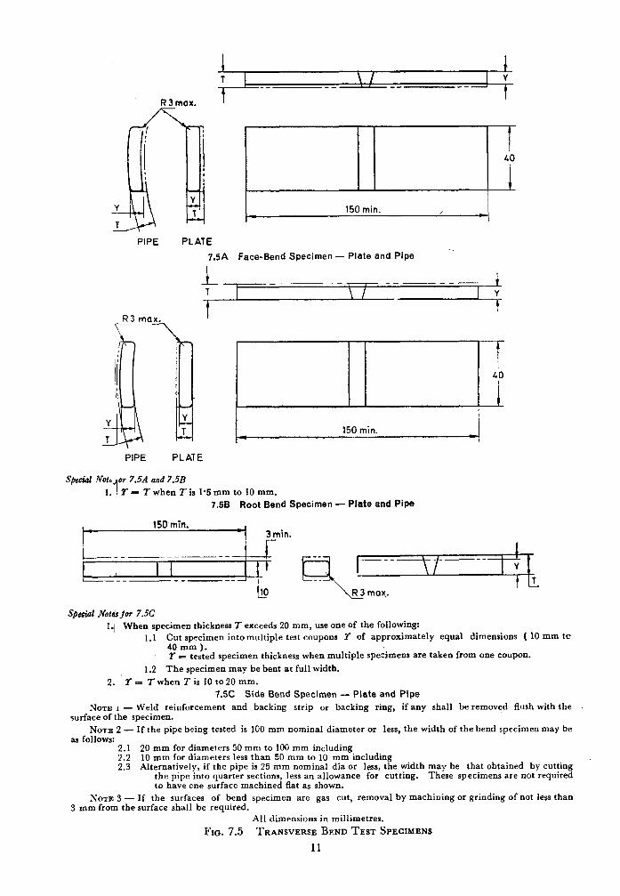
‘\ I
R 3 max.
i 1 T \ I 1 Y
_- -_ , -_ --A
t
150 min. / I
PIPE PLATE
--_ 7.5A Face-Bend Specimen - Plate and Pipe
1 ----- ----- 1 T \ I 1 ”
iili!L -. I 40
I
Y Y T 150 min.
T
PIPE PLATE
Spcciol Not. or 7.5A and 7.5B
1. 1 r = 7 when T is I.5 mm to 10 mm.
7.58 Root Bend Specimen - Plate and Pipe
150 min. J 3min.
/___,_~______ I
I , I I t+ L-C-___-__a
10
qwiar Notdrfor 7.5c
I.1 When specimen thickness I exceeds 20 mm, use one of the following: 1.1 Cut specimen intomultiple test coupons Y of approximately equal dimensions ( 10 mm tc
40 mm ). X = tested specimen thickness when multiple specimens are taken from one coupon.
1.2 The specimen may be bent at full width. 2. ‘T= TwhenIis lOto20mm.
7.5C Side Bend Specimen - Plate and Pipe
NOTE I - Weld reinforcement and backing strip or backing ring, if any shall be removed flush with the surface of the specimen.
NOTE 2 - If the pipe being tested is 100 mm nominal diameter or less, the width of the bend specimen may be as follows:
2.1 20 mm for diameters 50 mm to 100 mm including 2.2 10 mm for diameters less than 90 mm to 10 mm including 2.3 Alternatively, if the pipe is 25 mm nominal dia or less, the width may be that obtained by cutting
the pipe into quarter sections, less an allowance for cutting. These specimens are not required to have one surface machined flat as shown.
NOTE 3 - If the surfaces of bend specimen are gas cut, removal by machining or grinding of not less than 3 mm from the surface shall be required.
All dimensions in millimetres.
FIG. 7.5 TRANSVERSE BEND TEST SPECIMENS
11
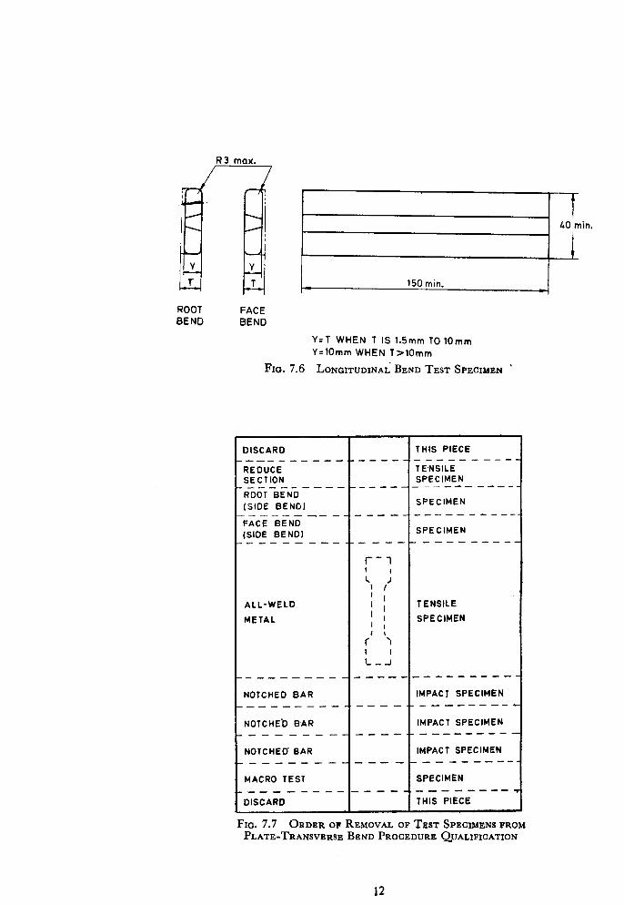
R3 max.
I
I LO min.
I
4 150 min. c
ROOT FACE BEND BEND
Y=T WHEN T IS 1.5mm TO 1Omm Y=lOmm WHEN T>lOmm
FIG. 7.6 LONGITUDINAL BEND TEST SPECIMEN ’
DISCARD
REDUCE SECTION
[SIDE BEND) _-_-_-
THIS PIECE ---__
TE%lLi
SPECIMEN ---_A_ ----
SPECIMEN -----we---
FACE BEND
(SIDE BEND1 I I SPECIMEN _____-__-_+-----_--------
ALL-WELD I ’ I ;
TENSILE
METAL 1 I
SPECIMEN
1 r’ ‘> ;__I
-___---- _------ ___---- NOTCHED BAR IMPACT SPECIMEN
._________ ____ -._-__-----~
NOTCHEb BAR IMPACT SPECIMEN ____________._-__--__-.
NOTCHED’ BAR IMPACT SPECIMEN .-----_-__--_--m-w --_-
MACRO TEST SPECIMEN
-___---__-___,_-___---
DISCARD THIS PIECE
FIG. 7.7 ORDER OF REMOVAL OF TEST SPECIMENS FROM PLATE-TRANSVERSE BEND PROCEDURE QUALIFICATION
12
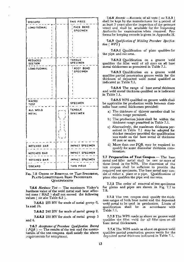
I .
_------ NOTCHED BAR ___----- NOTCHED BAR ___-----
NOTCHED BAR --__-e-m-
DISCARD -- -----5
LONGITUDINAL I
__-_- IGUCEO
-I
SECTION ----e-e-
I LONGITUDINAL ,
MACRO- --a -I
TEST _-_----a.
ALL WELD
METAL
_--
.--
---
---
--.
r-i
'1 J 1 I
1 I
’ 1 I
I : r ’ I I - _ -1
_--
---
---
---
IHIS PIECE
i------- , FACE BEND
, SPECIMEN
_I__--_--
TENSILE SPECIMEN T_---c--
’ ROOT BEND ’ SPECIMEN
.I
I___---
SPECIMEN ._- ----- TENSILE
SPECIMEN
--e--w--
IMPACT SPECIMEN -------
IMPACT SPECIMEN -------
IMPACT SPECIMEN -_---_---
THIS PIECE
FIN. 7.8 ORDER OF REMOVAL OF TEST SPINIMENS, PLATE-L• NGXTUDINAL BEND PROCEDURES
QUALIFICATION
7.6.6 Hardness Test - The maximum Vicker’s hardness value of the weld metal and heat affec- ted zone ( HAZ ) shall not exceed the following values ( see also Table 6.3 ).
7.6.6.1 225 HV for steels of metal group 0, laand lb.
13
7.6.6.2 240 HV for steels of metal group 2.
7.6.6.3 250 HV for steels of metal group 3 and 4.
7.6.7 Acceptance of Procedure Qualzjkation Record
(PQR) - The results of the test and the exami- nation of the test coupons shall satisfy the above requirements for acceptance.
7.6.8 Records -Records of all tests ( see 7.1.3 ) shall be kept by the manufacturer for a period of at least 5 years after the inspection of the pressure vessel and shall be available for the Inspecting Authority for examination when required. Pro- forma for keeping records is given in Appendix H.
7.6.9 Qualification of Welding Procedure Specr$caca- tion ( WPS)
7.6.9.1 Qualification of plate qualifies for the pipe and vice versa.
7.6.9.2 Qualification on a groove weld qualifies the fillet weld of all sizes on all base metal thicknesses as permitted in Table 7.1.
7.6.9.3 Qualification on a groove weld qualifies partial penetration groove welds for the thickness of deposited weld metal qualified as indicated in Table 7.1.
7.6.9.4 The range of base metal thickness and weld metal thickness qualified as is indicated in Table 5.1.
7.6.9.5 WPS qualified on groove welds shall be applicable for production welds between dissi- milar base metal thicknesses provided:
4
b)
cl
The thickness of thinner member shall be within range permitted.
The production joints shall be within the thickness range permitted in Table 7.1.
Alternatively, the maximum thickness per- mitted in Table 7.1 may be adopted for thicker member provided the qualification was made on the base metal of thickness 40 mm or more.
More than one PQR may be required to qualify for some dissimilar thickness com- bination.
7.7 Preparation of Test Coupon - The base. metal and filler metal shall be one or more of those listed in the WPS. The dimension of the test coupon shall be sufficient to provide the required test specimens. The base metal may con- sist of either a plate or a pipe, Qualifications of plate also qualifies the pipe and vice versa.
7.7.1 The order of removal of test specimens for plates and pipes are shown in Fig. 7.7 to 7.9.
7.7.2 The test coupon shall qualify the thick- ness ranges of both base metal and the deposited weld metal to be used in production. Limits of qualification shall be in accordance with Table 7.1.
7.7.3 The WPS made as above on groove weld qualifies the fillet weld for all fillet sizes on all base metal thicknesses.
7.7.4 The WPS made as above on groove weld qualifies partial penetration groove welds for the deposited metal thickness indicated in Table 7.1.
REDUCED SECTION
NOTCHED BAR IMPACT
I
NOTCHED BAR IMPACT
I
(SlOti BEND) (SIDE BEND)
NOTE - Weld extra test piece to accommodate one extra transverse tensile specimen in place of all weld metal tensile and to accommodate three impact specimens, if required.
FIG. 7.9 ORDER OF REMOVAL OF TEST SPECIMENS, PIPE-PROCEDURE QUALIFICATION
7.8 Welder’s Performance Qualification
7.8.1 Each manufacturer or contractor shali be responsible for conducting tests to qualify the performance of the welders or welding operators in accordance with one of this welding procedure specification ( WPS ). The welders or welding operators shall be tested under the supervision and control of the manufacturer or contractor. The welding performed by the welder or welding operator in another organization is not to be considered.
7.8.2 QuaYiJcation Tests - The performance qualification tests are intended to determine the ability of the welder or welding operator to make sound welds. The manufacturer or contractor shall qualify each welder or welding operator for each welding process to be used in production welding. The performance tests can be either for groove weld or for fillet weld.
7.8.2.1 The welder or welding operator who welds the PQR test coupons is also qualified with- in the limits of the performance qualification listed in this section ( see 7.8.5 ).
7.8.2.2 A welder or welding operator quali- fied to weld in accordance -with one qualified WI’S is also qualified to weld in accordance with other qualified WPS using the same welding process within the limits of variables listed in this section ( see 7.8.7 ).
7.8.2.3 Each qualified welder or welding operator shall be assigned an identification which shall be used to identify the work of that welder or welding operator.
7.8.2.4 The record of welder or welding operator performance tests shall be kept by the manufacturer. This shall include the welding variable, the type of test, tests results and ranges qualified for each welder and welding operator. Pro-forma for Appendix H.
keeping records is given in
7.8.3 Groove Welds
7.8.3.1 Mechanical test - The type and num- ber of test specimens required shall be in accord- ance with Table 7.2. The order of removal of test specimen is shown in Fig. 7.10. The acceptance shall be in accordance with 7.6.
. .
7.8.3.1.1 Mechanical testing as given in Table 7.2 may be substituted by radiography on a test bed of 225 mm length. Acceptance standard for radiography shall be as per Class I vessels. Qualification by radiography is not permitted for gas metal arc welding.
7.8.3.2 Test coupon for pipes - i’he test coupons for pipes shall be removed as shown in Fig. 7.1 I for mechanical testing. The acceptance shall be in accordance with 7.6.
14
TABLE 7.2 GROOVED- WELD PERFORMANCE QUALIFICATIONS THICKNESS LIMITS AND TEST SPECIMENS
( cluusc 7.8.3.1 )
c
THICxNPss l- OB
THE TEST COUPCN WELDED
( see NOTE 1 ) mm
up to 10 10 but less than 20
20 and above
TBICENESS t OR DEPOSITED WELD
TYPE AND NUMBER OB TEST REQUIRED C--------__h__
METAL QUALIFIED Side Bend Face Bend --------7 Root Bend Macro
( scc 7.8.6 AND ( see Notes 3 and NOTE 2 )
4 )
mm
2t ( J-CC Note 5 ) 1 1 1
2t 2 -_ 1
Maximum to be welded
2 - - I
NOTE 1 - The entire thickness of groove joint test coupon shall be filled with deposited weld metal.
NOTE 2 - TWO or more pipe test coupons of different thicknesses may be used to determine the deposited weld metal thickness qualified and that thickness may be applied to production welds to the smallest diameter for which the welder is qualified.
NOTE 3 - A total of four specimens is required to qualify for multiple positions as prescribed in Fig. 7.11B.
NOTE 4 - Face and root-bend tests may be used to qualify combination test of:
4.1 One welder using two welding processes; or
4.2 Two welders using the same or a different welding process.
NOTE 5 - Two side bend teats may be substituted for the required face and root-bend tests.
DISCARD
ROOT BEND (SIDE BEND) --_--- FACE BEND
(S!DE BEND) ---_--
MACRO TEST ------
DISCARD
I I SPECIMEN
I
7.10A Transverse Bend
I- IISCARD I THIS PIECE _----- .ONGITUDINAL
l-
FACE BEN0 ;
.--- - I-
.ONGITUOINAL ,
ROOT BEND ,
--
~
-
-I-- ----
, SPECIMEN
- I- - ---
SPECIMEN
_---- I- -_I_____
MACRO t I SPECIMEN
TEST
1
DISCARD I
THIS PIECE
7.106 Longitudinal Bend
Fro. 7.10 ORDER OF REMOVAL OF TEST SPECIMEN, PLATE - PERFORMANCE QUALIFICATION
1.8.4 Fillet Welds taken as shown in Fig. 7.12 and Fig. 7.13 and shall be loaded laterally in such a way that the
7.8.4.1 Mechanical test - For fillet welds, root of the weld is in tension. The load shall be fracture test and macro examination shall be done. steadily increased until the specimen fractures or The dimension and preparation of test specimen shall be in accordance with Fig. 7.12 for plate
bends flat upon itself. The fractured surface shall show no evidence of cracks or incomplete root
and Fig. 7.13 for pipe. The test specimen shall fusion and the sum of the length of inclusion and porosity visible on the fractured surface shall not exceed 10 mm for plate and 10 percent of the
not contain any viiible cracks.
7.8.4.2 The specimen for fracture test is quarter section for pibe.
15
FACE BEND . J&T BEND MACRO ’
YE BEND) I- WE BEND
L!- MACRO \ /&CE BEND ROOT BEND (SIDE BEND) (SIDE BEND)
7.11A Fiat or Horizontal 7.11B Multiple Horizontal and Multiple-Inclined
Fro. 7.11 ORDER OF REMOVAL OF TEST SPECIMZNS, PIPE-PERFORMANCE QUALIFICATION
DIRECTION OF BENDING
P AND RESTART WELD AR THE CENTRE
100 j \MAXIM”M FILLET SltE=t MACRO TEST
SPECIMEN
t = 5mm TO 1Omm
All dimensions in millimetres.
FIQ. 7.12 FILLET WELD IN PLATE-PERFORMANCE QUALIFICATION
DIRECTION OF BEND
/-
IMUM FILLET
t = WALL THICKNESS
Norm - Either pipe to plate or pipe to pipe may ie used as shown. All dimensions in millimetres.
FIG. 7.13 FILLET WELD IN PIPE-PERFORMANCE QUALIFICATIOS
16
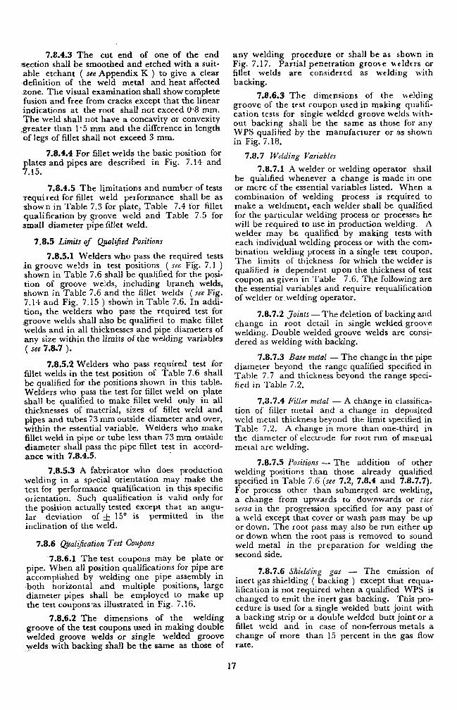
7.8.4.3 The cut end of one of the end section shall be smoothed and etched with a suit- able etchant ( see Appendix K ) to give a clear ,definition of the weld metal and heat affected zone. The visual examination shall show complete fusion and free from cracks except that the linear indications at the root shall not exceed O-8 mm. The weld shall not have a concavity or convexity
.greater than l-5 mm and the difference in length of legs of fillet shall not exceed 3 mm.
7.8.4.4 For fillet welds the basic position for plates and pipes are described in Fig. 7.14 and 7.15.
7.8.4.5 The limitations and number of tests required for fillet weld performance shall be as shown in Table 7.3 for plate, Table 7.4 for fillet qualification by groove weld and Table 7.5 for ,small diameter pipe fillet weld.
7.8.5 Limits of QualiJied Positions
7.8.5.1 Welders who pass the required tests in groove welds in test positions ( see Fig. 7.1 ) shown in Table 7.6 shall be qualified for the posi- tion of groove welds, including branch welds, shown in Table 7.6 and the fillet welds (see Fig. 7.14 and Fig. 7.15 ) shown in Table 7.6. In addi- tion, the welders who pass the required test for groove welds shall also be qualified to make fillet welds and in all thicknesses and pipe diameters of any size within the limits of the welding variables ( see 7.8.7 ).
7.8.5.2 Welders who pass required test for fillet welds in the test position of Table 7.6 shall be qualified for the positions shown in this table. Welders who pass the test for fillet weld on plate shall be qualified to make fillet weld only in all thicknesses of material, sizes of fillet weld and pipes and tubes 73 mm outside diameter and over, within the essential variable. Welders who make fillet weld in pipe or tube less than 73 mm-outside diameter shall pass the pipe fillet test in accord- ance with 7.8.4.5.
7.8.5.3 A fabricator who does production welding in a special orientation may make the test for performance. qualification in this specific orientation. Such qualification is valid only for the position actually tested except that an angu- lar deviation of f 15” is permitted in the inclination of the weld.
7.8.6 @al$cation Test Coujons
7.8.6.1 The test coupons may be plate or pipe. When all position qualifications for pipe are accomplished by welding one pipe assembly in .both horizontal and multiple positions, large diameter pipes shall be employed to make up the test coupons-as illustrated in Fig. 7.16.
7.8.6.2 The dimensions of the welding groove of the test coupons used in making double welded groove welds or single welded groove yelds with backing shall be the same as those of
any welding procedure or shall be as shown in Fig. 7.17. Partial penetration groove wtldtrs or fillet welds are considered as welding with backing.
7.8.6.3 The dimensions of the welding groove of the test coupon used in making qualifi- cation tests for single welded groove welds with- out backing shall be the same as those for any WPS qualified by the manufacturer or as shown in Fig. 7.18.
7.8.7 Welding Variables
7.8.7.1 A welder or welding operator shall be qualified whenever a change is made in one or mere of the essential variables listed. When a combination of welding process is required to make a weldment, each welder shall be qualified for the particular welding process or processes he will be required to use in production welding. A welder may be qualified by making tests with each individual welding process or with the com- bination welding process in a single test coupon. The limits of thickness for which the welder is qualified is dependent upon the thickness of test coupon as given in Table 7.6. The following are the essential variables and require requalification of welder or welding operator.
7.8.7.2 Joints - The deletion of backing and change in root detail in single welded groove welding. Double welded groove welds are consi- dered as welding with backing.
7.8.7.3 Base metal - The change in the pipe diameter beyond the range qualified specified in Table 7.7 and thickness beyond the range speci- fied in Table 7.2.
7.8.7.4 Filler metal - A change in classifica- tion of filler metal and a change in deposited weld metal thickness beyond the limit specified in Table 7.2. A change in more than one-third in the diameter of electrode for root run of manual metal arc welding.
7.8.7.5 Positions - The addition of other welding positions than those already qualified specified in Table 7.6 (see 7.2, 7.8.4 and 7.8.7.7). For process other than submerged arc welding, a change from upwards to downwards or r:zce versa in the progression specified for any pass of a weld except that cover or wash pass may be up or down. The root pass may also be run either up or down when the root pass is removed to sound weld metal in the preparation for welding the second side.
7.8.7.6 Shielding gas - The emission of inert gas shielding ( backing ) except that requa- lification is not required when a qualified WPS is changed to emit the inert gas backing. This pro- cedure is used for a single welded butt joint with a backing strip or a double welded butt joint or a fillet weld and in case of non-ferrous metals a change of more than 15 percent in the gas flow rate.
17
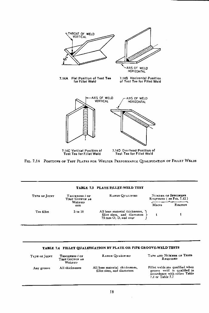
\AXIS OF WELD HORIZONTAL
7.14A Fiat Position of Test Tee 7.14B Horizontal Position for Fillet Weld of Test Tee for Fillet Weld
AXIS OF WELD AXIS OF WELD
7.14C Vertical Position of 7.140 Overhead Position of Test Tee for Fillet Weld Test Tee for Fillet Weld
FIG. 7.14 POSITIONS OF TEST PLATES FOR WELDER PERFORMANCE QUALIFICATION OF FILLET WELDS
TABLE 7.3 PLATE FILLET-WELD TEST
TYPE OB JOINT THICKNESS t cm RANGE QUALIBIED NUMBER OF SPECIMENS TEST COUPON AS REQUIRED ( see FIQ. 7.12 1
WELDED c-_-~---~ mm Macro Fracture
Tee fillet 5 to 10 All base material thicknesses, fillet sizes, and diameters 73 mm 0. D. and over
1
TABLE 7.4 FILLET QUALIFICATION BY PLATE OR PIPE GROOVE-WELD TESTS
TY_PE OF JOINT TEICKNESS~ OF RANQE QUALIFIED TYPE AND NUXBER OF TESTS TEST COUPON AS REQUIRED
WELDED
Any groove All thicknesses All base material thicknesses, fillet sizes, and diameters
Fillet welds are qualified when weld is qualified in
%~~~~ance with either Table 7.1 or Table 7.7
18
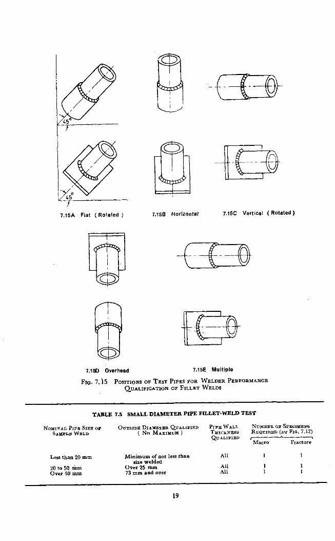
7.15A Flat (Rotated j 7.158 Horizontal 7.15C Vertical ( Rotated )
7.1%) Overhead 7.15E Multiple
Fro. 7. i5 P~SITIOPIS OF TEST PIPES FOR WELDER PERFORMANCE QUALIFICATION OF FILLET WELDS
TABLE 7.5 SMALL DIAMETER PIPE FILLET-WELD TEST
NOMINAL PIPE SIZE OB SAMPLE WELn
OUTSIDE DIAMETXUI QUALIFIED PIPE WALL NUMBER OB SPECIMENS ( No MAXIMUM ) THICKNESS REQUIRED (m Fm. 7.12)
QUALIFIED y-_---h-_---~
Macro Fracture
Less than 20 mm
20 to 50 rhm Over 50 mm
Minimum of not less than size welded
Over 25 mm 73 mm and over
All 1 1
All 1 1 All 1 1
19
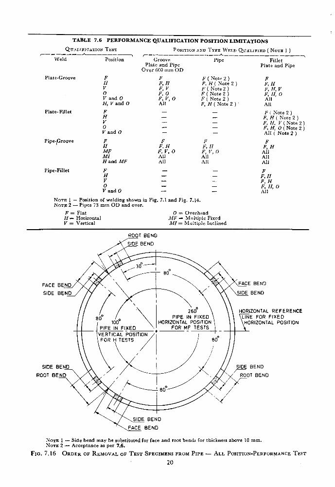
TABLE 7.6 PERFORMANCE QUALIFICATION POSITION LIMITATIONS
QVBLIFICATION TEST POSITION AND TYPE WELD QVLLIFIED ( NOTE 1 ) r------- h_-____-_T r-------__-_,___h
Weld Position -_-_-----__---~
Groove Pipe Fillet Plate and Pipe
Over 600 mm OD Plate and Pipe
Plate-Groove F F
v” i, H
F ( Note 2 ) F, H ( Note 2 ) F, H F ( Note 2 )
0 20” F, H, V
V and 0 F: V, 0 F ( Note 2 ) F, H, 0 F ( Note 2 ) All
H, V and 0 All F, H ( Note 2 ) All
Plate-Fillet ;
- - F i Note 2 ) - -
0”
F, H ( Note 2 ) - - F, H, V ( Note 2) - -
V and 0 F, H, 0 ( Note 2 )
- - All ( Note 2 )
Pipe-)Groove F
2F MI Hand MF
F H
0” V and 0
F F
30 F, H FFH
All ’ F, V, 0 Ail All All
All All All
- - - - FFH - - F: H - - F, H, 0 - - All
Pipe-Fillet
NOTE 1 - Position of welding shown in Fig. 7.1 and Fig. 7.14. NOTE 2 - Pipes 73 mm OD and over.
F = Flat 0 = Overhead H = Horizontal MF = Multiple Fixed V = Vertical MI = Multiple Inclined
ROOT BEND
BEN3
L REFERENCE FIXED
TAL POSITION
SIDE BEND
NOTE 1 - Side bend may be substituted for face and root bends for thickness above 10 mm. NOTE 2 - Acceptance as per 7.6.
FIG. 7.16 ORDER OF REMOVAL OF TEST SPECIMENS FROM PIPE - ALL POSITION-PERFORMANCE TEST
20
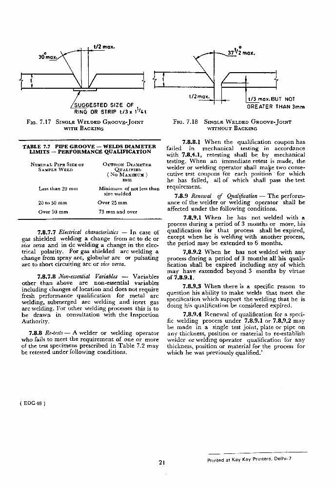
/SUGGESTED slzE 0F ,,
RING OR STRIP t/3 x 1 bt
FIN. 7.17 Smahe WELDED GROOVE-JOINT WITH BACKING
TABLE 7.7 PIPE GROOVE - WELDS DIAMETER LIMITS - PERFORMANCE QUALIFICATION
NOMINAL PIPE SIZE cm OUTSIDE DIAMETER SAMPLE WELD QUALIFIEIJ
( No MAXIMUM ) mm
Less than 20 mm Minimum of not less than size welded
20 to 50 mm Over 25 mm
Over 50 mm 73 mm and over
7.8.7.7 Electrical characteristics - In case of gas shielded welding a change from ac to dc or vice versa and in dc welding a change in the elec- trical polarity. For gas shielded arc welding a change from spray arc, globular arc or pulsating arc to short circuiting arc or vice versa.
7.8.7.8 fin-essential Variables - Variables other than above are non-essential variables including changes of location and does not require fresh performance qualification for metal arc welding, submerged arc welding and inert gas arc welding. For other welding processes this is to be drawn in consultation with the Inspection Authority.
7.8.8 Re-tests - A welder or welding operator who fails to meet the requirement of one or more of the test specimens prescribed in Table 7.2 may be retested under following conditions.
t’2m* ~tox.BUT NOT
GREATER THAN 3mm
FIG. 7.18 SINGLE WELDED GROOVE-JOINT WITHOUT BACKING
7.8.8.1 When the qualification coupon has failed in mechanical testing in accordance with 7.8.4.1, retesting shall be by mechanical testing. When an immediate retest is made, the welder or welding operator shall ma$e two conse- cutive test coupons for each position for which he has failed, all of which shall pass the test requirement.
7.8.9 Renewal of Qualz$cation - The perform- ance of the welder or welding operator shall be affected under the following conditions.
7.8.9.1 When he has not welded with a process during a period of 3 months or more, his qualification for that process shall be expired, except when he is welding with another process, the period may be extended to 6 months.
7.8.9.2 When he has not welded with any process dnring a period of 3 months all his quali- fication shall be expired including any of which may have extended beyond 3 months by virtue of 7.8.9.1.
7.8.9.3 When there is a specific reason to question his ability to make welds that meet the specification which support the welding that he is doing his qualification be considered expired.
7.8.9.4 Renewal of qualification for a speci- fic welding process under 7.8.9.1 or 7.8.9.2 may be made in a single test joint, plate or pipe on any thickness, position or material to re-establish welder or welding operator qualification for any thickness, position or material for the process for which he was previously qualified.’
(EDC48)
21 Printed at Kay Kay Printers, Delhi-7