is 6607 (1972): rebated mortice locks(vertical type) · is:6607-1972 indian standard specification...
TRANSCRIPT

Disclosure to Promote the Right To Information
Whereas the Parliament of India has set out to provide a practical regime of right to information for citizens to secure access to information under the control of public authorities, in order to promote transparency and accountability in the working of every public authority, and whereas the attached publication of the Bureau of Indian Standards is of particular interest to the public, particularly disadvantaged communities and those engaged in the pursuit of education and knowledge, the attached public safety standard is made available to promote the timely dissemination of this information in an accurate manner to the public.
इंटरनेट मानक
“!ान $ एक न' भारत का +नम-ण”Satyanarayan Gangaram Pitroda
“Invent a New India Using Knowledge”
“प0रा1 को छोड न' 5 तरफ”Jawaharlal Nehru
“Step Out From the Old to the New”
“जान1 का अ+धकार, जी1 का अ+धकार”Mazdoor Kisan Shakti Sangathan
“The Right to Information, The Right to Live”
“!ान एक ऐसा खजाना > जो कभी च0राया नहB जा सकता है”Bhartṛhari—Nītiśatakam
“Knowledge is such a treasure which cannot be stolen”
“Invent a New India Using Knowledge”
है”ह”ह
IS 6607 (1972): rebated mortice locks(vertical type) [MED33: Utensils, Cutlery and Domestic Hardware]

IS : 6607 - 1972
Indian Standard SPECIFICATION FOR REBATED
MORTICE LOCKS (VERTICAL TYPE)
Bulder’s.Hardware Sectional Committee, BDC 15
Chaimkan SRRI Yusup MOWJEE
Rcficscnting M. C. Mowjee & Company, Calcutta; and Builder’s
Hardware Industries Association of India, Calcutta
Members
SHRI SamB SlMOR ( Aiterna~ to Shri Yusuf Mowjee )
SHRI D. R. BAWL Engineer-in-Chief’s Branch, Army Headquarters SHRI P. K. SETHI ( Alternate )
SHRI J. P. BAJAJ Institution of.Engineers ( India), Calcutta
Sxax A. K. B~rx~rn Vertex Manufacturing Company Limited, Bombay
SHRI H. C. SA~AT ( Ahaate ) SHRI R. M. CHAWNRT Indian Aluminium Company Limited, Calcutta
SHRX J. K. ANAND ( ANcrnate ) CONTROLLER OF STORES,
EASTERN RAILWAY
SHRI P. K. DE SHRI R. L. GERLOTE SHRI K. P. JAIN SHRI V. S. KAMBOJ SHRI J. R. KANSARA
SHRI V. S. KAMBOJ ( Alfernafc )
SHRI S. C. KAPOOR
Railway Board ( Ministry of Railways )
De’s Lock Industries, Calcutta Indian Institute of Architects, Bombay Engineering Association of India, Calcutta
Jayna Trading Corporation, Delhi Arvind Industries, Jamnagar ( Gujarat )
SHRI S. D. MAJUMDAR SHRI AJOYENDU PAUL
DR A. V. R. Rno SURVEYOR OF WORKS (I) SHRI D. AJITHA Sctfm,
Director ( Civ Engg )
Directorate General of Supplies & Disposals ( Ministry of Supply )
National Test House, Calcutta Gob~~nut~heet Metal Works and Foundry,
National Buildings Organization, New Delhi Central Public Works Department, New Delbi Director General, IS1 ( ikojicio Member)
Secre tqy
SHRI S. P. MAGGU
Senior Technical Assistant ( Civ Engg ), IS1 ( Conrinurd on &gr 2 )
INDIAN STANDARDS INSTITUTION MANAK BHAVAN, 9 BAJ3AlXJR SHAH ZAFAR MARG
NEW DELHI ‘110002

IS:6607-1972
( Conhwedfrom jaga 1 )
Locks and Latches Subcommittee, BDC 15 : 3
Convener
SHRI J. R. SACHDEVA
Members
SHRI K. C. MISRA ( Alternate to Shri J. R. Sachdeva )
SHRI MAHABIRPRASADAOARWAL SHXIR. C. BHATTACHARYYA
SHRI A. K. BHIMAN'I SHRI H. C. SAMPAT (Al!ernate)
SHRI P. K. DE
Represenhg
Defence Production Organization ( Ministry of Defence )
Gopal Metal and Wood Works, ALigarh Directorate of Industries, Government of West
Bengal Vertex Manufacturing Co Ltd, Bombay
SHRI S. F. DESAI SHRI VINOD KTJMAR JAIN SHRl u. c. LALL
De’s Lock Industries, Calcutta Godrej & Boyce Mfg Co Pvt Ltd, Bombay P.P. Products, Aligarh Hemu Productions ( India), Calcutta
SHRI S. P. JHUNJHUKWALA ( Alternate ) SHRX MOHAN SINGH Eastern Commercial & Industrial Enterprises Pvt
Ltd, Bombay SHRI S. S. GANDHI ( Altemafe)
SHIU N. P. SArPATi Directorate of Industries, Government of Mabarashtra
SHRX G. S. SUBBARAMAN Directorate General of Supplies & Disposals
SHRI YUSUP MOWJEE ( Ministry of Supply )
SHRX SAHIB SWGH ( Alternate ) M. C. Mowjee & Co, Calcutta

IS:6607-1972
Indian Standard SPECIFICATION FOR REBATED
MORTICE LOCKS ( VERTICAL TYPE )
0. FOREWORD
0.1 This Indian Standard was adopted by the Indian Standards Institution on 4 August 197.2, after the draft finalized by the Builder’s Hardware Sectional Committee had been approved by the Civii Engineering Division Council.
0.2 Mortice locks have become popular and are being used in all modern buildings specially where flush doors are provided. Certain situations demand the use of double leaf doors and ordinary mortice locks cannot serve the purpose because of the special rebate pattern involved. To cater to the specific problem of double leaf doors, rebated mortice locks have to be provided. It is with. this edd in view that this standard is being issued.
0.3 Wherever reference to mortice lock appears in the standard it shall mean a rebated mortice lock.
0.4 In the formulation of this standard due weightage has been given to international co-ordination among the standards and practices prevailing in different countries in addition to relating it to the practices in the’field in this country.
0.5 This standard contains clauses 2.2, 5.1.1,7.1.2,8.1,9.1.1 and 10.1 which permit the purchaser to use his option for selection to suit his requirements and clauses 6.1 and 6.2 and Appendix A which require the purchaser to supply certain technical information at the time of placing orders.
0.6 This standard is one of a series of standards on builder’s hardware.
0.7 While preparing this standard, the Sectional Committee took note of the acute scarcity of non-ferrous materials like copper, zinc and other alloys in the country and the need for conserving the use of the same in the national interest. However, in view of the demand for hardware items made of these materials in overseas markets, the Sectional Committee has retained them specifically to meet the requirements of export trade. For all indigenous use, it is recommended that hardware items made out of these materials should not be used.
3

IS : 6607 - 1972
0.8 For the purpose of deciding whether a particular requirement of this standard is complied with, the final value, observed or calculated, express- ing the result of a test or analysis, shall be rounded off in accordance with IS : 2-1960*. The number of significant places retained in the round- ed off value should be the same as that of the specified value in the standard.
1. SCOPE
1.1 This standard lays down the requirements for rebated mortice locks suitable for use on double leaf doors with rebated meeting stiles.
2. SIZE
2.1 The sizes of mortice locks shall be as follows:
65 mm, 75 mm and 100 mm.
2.1.1 The size of the lock- shall be denoted by the overall length of the body measured from the outside face of the fore end to the rear end ( see Fig. 1). The measured length shall not vary more than & 3 mm from the length specified for the size.
2.2 Mortice locks ofsizes other than those specified in 2.1 may be supplied by mutual agreement between the purchaser and the supplier.
3. MATERIAL
3.1 Material used for different component parts of the locks shall comply with the reqmrements given in Table 1 (see P 8, 9, 10 and 11 ).
4. SHAPE
4.1 The shape, design and mechanism of mortice locks and its component parts indicated in Fig. 1 are illustrative only. The manufacturer may make mortice locks of other shapes to suit his design.
5. DIMENSIONS
5.1 The leading dimensions of the mortice locks ( suitable for double-leaf doors ) shall be normally as given in Fig. 1.
5.1.1 It may be manu between the manufactur
*Rules for rounding off numerical values ( rc&d ).
4

ASSEMBLY WITHOUT BOQY COVER
(I) Body (2) Case/Face Plate (3) Locking Bolt (4) Latch Bolt
4g.
II
tl _@_
j-+25-
@ CASE/FACE PLATE
f LEVER SPRING FULCRUM PIN
@ BODY
STRIKING PLATE
(5) (6) (7)
1.25 MIN THICK
7
Lever Latch Spring Follower
I
@ LATCII BOLT
+===s @ LOCKING BOLT
@ LEVER
\-8mmSQ HOLE FOR CONNECTING ROD
@ FOLLOWER KEY
LATCH SPRING
All dimensions in millimetres. 5;
FIG. 1 TYPICAL DESIGN OF REBATED MORTICE LOCK ( VERTICAL TYPE ) ;1

As in the Original Standard, this Page is Intentionally Left Blank

IS : 6607 - 1972
6. NON-INTERCHANGEABILITY
6.1. Two-Lever Locks - The mortice locks shall be manufactured to have non-interchangeable keys in a batch consisting of a minimum of 24 locks. In case a non-interchageability in a higher number is required, it shall be so specified by the purchaser at the time of placing the order. A master- key may be supplied if required by the purchaser.
6.1.1 For the purpose of testing non-interchangeability, six locks from each batch of 24 locks shall be so selected that the wards of the keys differ from each other slightly. These locks shall then be tested for non-inter- changeability. If key of any of the locks opens any other lock, amongst the six locks, the whole lot shall be rejected.
6.2 Locks with More Than Two Levers - The mortice locks shall be manufactured to have non-interchangeable keys in a batch consisting of a minimum of IO0 locks. In case, non-interchangeability in a higher number is required, it shall be so specified if required by the purchaser.
6.2.1 For the purpose of testing non-interchangeability 12 locks from each batch of 100 locks shall be so selected that the wards of the keys differ from each other slightly. These locks shall then be tested for non-inter- changeability. If key of any one of the locks opens any other lock, amongst the 12 locks, the whole lot shall be rejected.
7. MANUFACTURE
7.1 Lock
7.1.1 Body - The depth of the body shall not be more than 15 mm.
7.1.2 Rebated Fore End - The case plate may itself form the rebated fore end. In case desired by the purchaser, in order to obtain a clean finish free from rivets, etc and to assist in decorating the rebate a rebated face plate may be provided. The rebated face plate shall be normallyfitted to the body by suitable countersunk head machine screws conforming to IS : 1365 ]gtj8* or by any other suitable device. In order to secure the rebated face plate threaded lugs shall be firmly attached to the case plate by either riveting or electric resistance welding or similar other suitable means.
7.1.2.1 In case of reversible mortice locks the rebated fore-end shall be so designed that the fore-end can be fixed in any direction by reversing its position through 180 degrees without causing any obstruction or deterioration in the working of the lock or the latch bolt. In case of reversible rebated mortice locks the size oflatch and lock bolt in cross-section shall be similar to each other.
*Specification for slotted countersunk head and slotted raised countersunk head screws ( dia range I.6 to 20 mm ) ( second revision j.
7

._ - ------ .--- ._ . ..-
C3
-.._ ---- --.--_ __ _
‘ir’AJtJ.E J REQIJII?J?IlENTS FOR I\IATJLJIJALS FOR C:OhlPONbNT PARTS OF MORTIC:E LOCKS g
((:lnrcs~~ 3.1, 7.15, 7.2.1 and 7.2.3) s t
(1) (2)
ii)
iii1
(;OhIPONEhT
(3)
Jbdy, body cover, cast plate, key. facr striking locking and latch bolt
(4) (5)

iV)
v)
vi) Alum&urn castings
alloy
vii) Aluminium alloy sheet
viii) Extruded aluminium alloy
Locking bolt and latch bolt
-
W *Specification for hot rolled carbon steel sheet and strip (sccandre&ion ).
tspecification for blackheart malleable iron castings.
$$ecification for brass ingots and castings ( mised).
@pecification for rolled brass plate, sheet, strip and foil ( second revision).
IlSpecification for free-cutting brass rods and sections ( second reoision ).
Brass sheet
Extruded brass
Body, body cover, plate, face plate, and striking plate
Locking bolt and bolt
case lever
The brass sheet shall meet the same bend test as specified for mild steel
latch Copper contents shall not t~;~less than 55 percent
tensile strength 35 kgjmms, Min
Body, body cover, follower and key
-
Body, body cover, case plate, striking plate, lever and face plate
-
Cast brasr cast from melt- ing sheet cuttings and brass utensils may be used. Grade CuZn 40 of IS : 410-19670
IS : 319~196811
IS Designation A-5-M or A-6-M of IS : 617-19597
IS Designation NS’ 4 or HS 20 ofIS : 737-1965**
IS Designation HE 30-WP of IS : 733-1967tt
~Specification for aluminium and aluminium alloy ingots and castings for general engineering purposes (revised).
**Specification for wrought aluminium and aluminium ( revised ) .
alloys, sheet and strip (for general engineering purposes)
ttspecification for wrought aluminium and aluminium alloys, bars, rods and sections ( for general engineering purposes ) tl . .
(first revision ) . % 3
( Conhud) ’ s s

tf . .
TABLE 1 REQUIREMENTS FOR MATERIALS FOR COil&PONENT PARTS OF MORTICE LOCKS - Conki ch g
SL No.
0)
ix)
x)
G
xi)
MATERIAL COMPONENT-
(2) (3)
Leaded tin bronze Follower and key
Zinc base alloy pressure die casting
Body, body cover, follower, face plate, striking plate, locking bolt and latch bolt
Phosphor bronze Lever spring and latch spring
REQUIREMENTS FOR MATERIAL
TYPICAL EXAMPLE
(4)
-
-
(5)
Grade 2 of IS : 318-1962*
IS : 742-19667
The wire used for springs shall comply with the test given below:
IS : 1385-19682
The lever spring shall be fitted into the lever as specified under 7.1.6 and shall be pressed down so as to touch the top edge of the lever and released. This shall be rrpcatcd six times minimum. At the end of the test the spring shall regain its origi- nal position

xii) Steel wire
E xiii) Stainless steel Key -
.ing and latch The wire used for sprirlgs Grade 1 or Grade 2 of shall comply with the Is : 4454-1967s test gi\ en below:
The levrr spring shall be fitted into the lever
specified under ;:l.S and shall br prcssrd down so as to touch the top edge Of the levrr and relravd. This shall be repeated six times mmlmum. At the end of the tesr the spring shall regain its origi- nal position
Grade 15 Cr 13, 22 Cr 13 or 30 Cr 13 of IS : 1570-196111
*Specification for leaded tin bronze ingots and castings (revised).
tSprcification for zinc base alloy die castings ( /irsf reuision ).
jS~)rcil~r ation for phosphor bronze rods and bars, sheet and strip, and wirr (J;rst rtvirion ).
$Slvxifi(,:ltion for steel wire, cold formed springs.
I/Slxcikation for schedules for wrought steels for gene,ral engineering p~lrposes.

ISt6607-1972
7.1.2.2 In case dissimilar sections are used for the manufacture of latch bolts and lockbolts for the reasons of strength the locks shall be designed as either suitable for left-hand doors or right-hand doors and the same shall be clearly marked on each lock.
7.1.3 Locking Bolt - The locking bolt shall be made out of a single metal or a combination of metals recommended for this part in Table 1. The bolts shall be of section not less than 12 x 16 mm for all sizes of locks. When steel locking bolt is provided, it shall be adequately protected against corrosion. In case of non-reversible locks the dimensions of locking bolt other than specified above may be used. In case of bolts made by casting the thickness of the bolt at no point in section shall be less than 4 mm. In case sheet steel is used in the manufacture of locking bolt the thickness of the steel sheet shall not be less than 1.6 mm.
7.1.4 Mechanism - The locking mechanism shall be of ordinary lever type or any other type approved by the purchaser.
7.1.5 Leuers - Ordinary lever machanism ( see Fig. 1 ) shall be provided with not less than two levers.
7.1.5.1 False ( dummy ) leaves shall not be used.
7.1.6 Lever Spring - Each lever shall be fitted with one spring which shall comply with the materials specified in Table 1. The lever spring fitted into the lever shall withstand the following test without showing any sign of permanent set:
The lever spring shall be pressed down so as to touch the top edge of the lever and released. This shall be repeated minimum six times.
7.1.7 Guide Pin, Lever Pivot Pin and Lever Spring Fulcrum Pin -The pins shall be SUitd_dy costed when used in conjunction with aluminium alloy body.
7.1.8 Kvs- Each lock shall be provided with two keys.
7.i.8.1 The key shall function smoothly and without any appreciable friction in the lock. The keys shall be suitably tied to the lock so that they are not lost or interchanged in transit. Malleable cast iron keys shall be protected against corrosion.
7.1.8.2 The lock shall be capable of being opened with the key from both: inside and outside.
7.1.9 Screw - The body cover shall be fitted to the body by countersunk head machine screws (see IS : 1365-1968” ). Screws shall be of mild steel and protected against corrosion,. where necessary. However the screws may be of aluminium alloy in the case of aluminium alloy bodies.
*Specification for slotted countersunk head and slotted raised countersunk head scre\+rs ( dia range 1.6 to 20 mm ) (second revision ).
12

IS : 6607 - 1972
7.2 Latch
7.2.1 Latch Bolt - The latch bolt shall be of single metal or a combina- tion of metals recommended for this prrrt in Table 1. The bolt shall be reversible to enable the Iock to be fixed on right-hand as we!1 as on the left- hand door. The ho!t shall be of section not less than 12 x 16 mm for ail sizes of locks. Where steel is provided it shall be adequately protected against corrosion. In case of non-reversible locks the dimensions of casting of latch bolt other than specified above may be used. In case of bolts made of castings the thickness of the bolt in sectton at no point shall be less than 4 mm. In case sheet steel is used in the manufacture of latch bolt the thickness of the steel sheet shall not be less than 1 .G mm.
7.2.2 Follower- It shall have a square hole at the centra to suit the spindle I+Thich operates the larch bolt. It shall be protected against corrosion when made from malleable iron.
7.2.3 Latch Spring- Each latch bolt shall be fitted Gth one spring which shall be of materials as specified in Table 1. The la[ch spring shall withstand the test as given in 7.1.6 without showing any sign of perma- nent set.
7.2.4 Striking Plate - The rebated striking plate shall have tlvo rectan- gular slots to suit the locking bolt and the latch bolt. It shall have two countersunk holes for fixing it to the rebated end of the door shutter.
8. WORKMANSHIP AND FINISH
8.1 Brass body shall be finished smooth and polished. .Yluminium alloy body may be anodized if required by the purchaser. shall not be inferior’to grade AC 15 of IS : 1868-1968”.
The anodic coating The rebated face
plate and the striking plate may be polishrd, stained, chromium plated or oxidised. Steel body shall be _b Given a suitable protective coating. Steel parts before painting shall be given the protective treatment in accordance with 8.1.1 and 8.1.2.
8.1.1 All dents, burrs and sharp edges shall be removed TIXXI-, :hls v.+ri!>us components and t!ley shall IX pick!ed, scrubl,ed and rinsed to rcrnove grease, rust, scale or’ any other foreign elemcmt.
8.1.2 After pickling, all the mild steel parts shall be given phospl~ati,lg treatment in accordance Tvith IS : 3618-l 966T followed by a coat of iititaj,ie primer, such as red oxide.
xo~~-Putty shal! br applied to all the surfaces rrquirinq fillinc and &ail conform to Is:426-!961:. ;1!uminium primer shall conform to IS: 2931-I%+$.
___-_ *Speclficatron for ano~hc coatings on alumm~um (jut rrLision ).
+Specification for phosphate treatment of iron a:~d steel for protection againct corrosioc. $Specikation for paste filler for colour coats t 7eisrd j. $Specifkation for read, mixed paint, brushing, al~timinium-zinc oxitlc I zniilosite primer.
13

IS : 6607 - 1972
8.1.3 Two coats of enamel paint shall then be applied as follows:
a) Undercoat, and
b) Finish coat with synthetic stoving enamel conforming to IS : 2932-1964* or IS : 2933-1964t.
6.1.3.1 The components shall thereafter be baked at a specified tem- perature in an oven heated uniformly. The finish shall be smooth and uniform with a hard and tough film of enamel s,trongly adhering to the surface. The finish shall be free from all visible defects and shall not chip, when tapped lightly with a pointed instrument.
9. TESTS
9.1 The fina!ly assembied lock shall withstand the tests specified in 9.1.1 to 9.1.6.
9.1.1 The locking bolt shall be first locked in the forward position. A load of 40 kg minimum or as agreed to between the manufacturer and the purchaser shah be applied without shock in the direction perpendicular to securing face as well as on both the locking faces of protruding bolt in turn. Then the load shall be applied by means of a fixed steel board 3 mm thick 1~. a rounded edge heid in such a position that the centre line is approxi- m~trlv 3 mm from the fore-end. A typical arrangement for the purpose of this test is shown in Fig. 2.
9.1.2 When the spindle with handle is inserted into hole in the follower and turned, the latch bolt shall draw smoothly into the lock body and shah be within one millimetre from the face of the fore-end.
9.1.3 When the latch bolt is pressed into the lock body by pressure, the action shall be smooth and when fully pressed the latch bolt shall not pro- ject more than one millimetre from the face of the fore-end.
9.1.4 The latch bolt shall be subjected to 50 000 operations .either man- ually or by mechanical means. At the end of the test the components should not show any undue movement from their normal position to cause imnediment to the smooth working of the,mechanism.
9.1.5 1Yhen a key is inserted in key hole from one side of the lock and turrted to withdraw the locking bolt the action shall be smooth and with- out impediment. 1Vhen the direction of turn is reversed to lock the lock- ing bolt then also the action shall be smooth and without impediment. In the locked position the locking bolt shall project 12 mm from the face of the fcre-end, although one millimetre free movement is permissible.
~~______.___ *Specification for’enamel, synthetic, exterior, Type 1, (a) undercoating, (b) finishing,
colour as required. tSpecification for enamel exterior, Type 2, (a) undercoating, (b) finishing, colour as
required.
14

IS:6607-1972
BEAM 75 cm LONG rFJ?ED BEARER
STEEL BAR 75 cm LONG APPROX
I II,/ I MOVABLE WEIGHT
i BASE
1 J FIG. 2 STRENGTH TEST FOR LOCKING BOLT
In the withdrawn position the locking bolt shall not project more than one millimetre from the face of the fore-end. The locking bolt shall be worked by turning key in both the directions several times quickly, limiting the total number of turns to 50 000. The purpose of this test is to check up that the components do not move from their normal position to cause impediment to the smooth working of the mechanism. This test shall be repeated with the key inserted from the either side of the lock.
9.1.6 When the key is turned to lock the locking bolt at the same time applying a reasonable pressure by finger on it, after completion of the ke) rotation the locking bolt shall be positively locked in the forward position. This test shall be repeated with the key inserted from the other side of the lock.
10. INSPECTION AND CERTIFICATE OF COMPLIANCE
10.1 The purchaser or his representative shall be permitted to inspect locks in open condition before purchasing, if he so desires.
10.2 Each manufacturer shall furnish? on request a certificate stating that the mortice locks comply with the requirements of this standard.
10.2.1 The manufacturer’s certificate shall be implied, if the lock bears the IS1 Certification Mark ( see II .l.l ).
llL_ _. _.._ _“.. - _._^..
IS : 6607 - 1972
11. MARKING
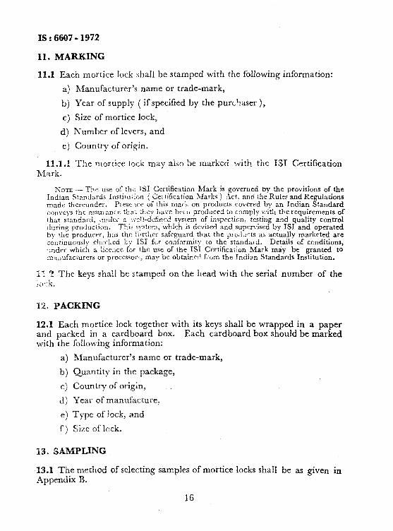
11.1 Each mortice Iock shall be stamped with the following information:
a) R$anufacturer’s name or trade-mark,
b) Year of supply ( if specified by the purchaser ),
c) Size of mortice lock,
d) Number of levers, and
e) Country of origin.
11.~2 The morrice lock may also be marked with the 181 Certification h4 a rk .
?;OTL -The use of thi TSI Certification Mark is governed by the provisions of the Indian Standards Instiru,lon ( &I tification Marks ) Act, and the Rules and Regulations made thereunder. Prese~tce of this mail. on products covered by an Indian Standard conveys tht assui ancc tha: :i,cy LA, 1’ 7.n bran produced to comply v:it!i th.e requirements of that standard, ;ll\der a :+-cjl-d&red system of inspection, testing and quality control during production. This s)stem, which is devised and supervised by ISI and operated by the producer, 11:~s the f:irther safeguard that the piodocts aa actually marketed are connnuouslv c!:xked L.; 1.51 for conformity to the standard. Details of conditions, .;nder which a liccncc for the use of the IS1 Certification Mark may be granted to ma,~ufacturcrs or processor:, may be obtained from the Indian Standards Institution.
I*. ? The keys shall be stamped on the head with the serial number of the ;<;+,
12. PACKING
12.1 Each mortice lock together with its keys shall be wrapped in a paper and packed in a cardboard box. Each cardboard box should be marked with the
a) b) c> 4 e) 4-x ‘I
following information:
Manufacturer’s name or trade-mark,
Quantity in the package,
Country of origin,
Year of manufacture,
Type of lock, and
Size of leek.
‘13. SAMPLING
13.1 The method of selecting samples of mortice locks shall be as given in
Appendix B.
16

IS : 6607 - 1972
APPENDIX A
( Clause 0.5 )
INFORMATION TO BE SUPPLIED BY THE PURCHASER WHEN PLACING AN ORDER FOR SUPPLY OF
MORTICE LOCKS
A-l. The purchaser shall furnish information to the manufacturer or the supplier in regard to the following points:
Whether the door is opening inside or outside ( of a person facing the door when standing outside the room );
Whether the door is with right or left overlap ( of a person facing the door when-standing outside the room );
Width of stile, if any;
Width of horizontal lockrail, if any;
Thickness of stile, lockrail, if provided, or thickness of shutter itself;
Depth of rebate; and
Angle of rebate.
NOTE - All locks are usually fitted to the overlapping shutter.
APPENDIX B
( Clause 13.1)
SAMPLING OF MORTICE LOCKS
B-l. SCALE OF SAMPLING
B-l.1 Lot - In any consignment, all the mortice locks of the same type, size and manufactured from the same material shall be grouped together to constitute a lot.
B-l.2 Sample Size--The number of mortice locks to be selected from a lot shall depend upon the size of the lot and shall be in accordance with co1 1 and 2 of Table 2.
B-1.2.1 Mortice locks for the sample shall be selected at random from at least 10 percent of the packages subject to a minimum of three packages, equal number of mortice locks being selected from each such package.
17

IS : 6607 - 1972
TABLE 2 SCALE OF SAMPLING AND PERMISSIBLE NUMBER OF DEFECTIVE MORTICB LOCKS
( C&use B-l .2 )
LOT SIZE SAmPLe SlZE htMEMIBLE NUHBZR OI DEFECTIVZ MORTXCE Locu
(1) (2) (3)
up to 200 15 0
201 ,, 300 20 1
301 f, 500 30 2
501 ,, 800 40 2 801 and above 50 3
---
B-2. TESTS
&2.X Ail the morticc locks selected as in B-I.2 shall be inspected for dimerisional requirements ( zee Fig. 1 ) and finish and workmanship ( Jw 5 j and for compIia.qcc-: with tests epecified in 9. Any mortice lock which fai!s to satisf)? any 3 e or more of the rcauireicenls for the &aracta-- &tic-: ::!:a11 be cor,sidered x defective mortice &k.
18
