is 7098-1 (1988): crosslinked polyethylene insulated …included in this standard....
TRANSCRIPT

Disclosure to Promote the Right To Information
Whereas the Parliament of India has set out to provide a practical regime of right to information for citizens to secure access to information under the control of public authorities, in order to promote transparency and accountability in the working of every public authority, and whereas the attached publication of the Bureau of Indian Standards is of particular interest to the public, particularly disadvantaged communities and those engaged in the pursuit of education and knowledge, the attached public safety standard is made available to promote the timely dissemination of this information in an accurate manner to the public.
इंटरनेट मानक
“!ान $ एक न' भारत का +नम-ण”Satyanarayan Gangaram Pitroda
“Invent a New India Using Knowledge”
“प0रा1 को छोड न' 5 तरफ”Jawaharlal Nehru
“Step Out From the Old to the New”
“जान1 का अ+धकार, जी1 का अ+धकार”Mazdoor Kisan Shakti Sangathan
“The Right to Information, The Right to Live”
“!ान एक ऐसा खजाना > जो कभी च0राया नहB जा सकता है”Bhartṛhari—Nītiśatakam
“Knowledge is such a treasure which cannot be stolen”
“Invent a New India Using Knowledge”
है”ह”ह
IS 7098-1 (1988): Crosslinked polyethylene insulated PVCsheathed cables, Part 1: For working voltage upto andincluding 1 100 V [ETD 9: Power Cables]


REAFFI~~!) d 0 0~, -- .'"
18 : 7011 ( P.rt 1 ).,_( R••fflrmed 2000 )
Indian Standard
SPECIFICATION FORCROSSLINKED POLYETHYLENE INSULATED
PVC SHEATHED CABLESPART 1 FOR WORKING VOLTAGES UP TO AND INCLUDING 1100 VOLTS
( First Revision)
Fourth Reprint SEPTEMBER 2003
UDC 621-315-221-8·678-742-2
C Copyright 1990
BUREAU OF INDIAN STANDARDSMANAK BHAVAN, 9 BAHADUR .SHAH ZAFAR MARG
NEW DELHI 110002
JIIIIIISfY 1990

AMENDMENT NO. 1 APRIL 1994TO
IS 7098 (PART 1) : 1988 CROSSLINKEDPOLYETHYLENE INSULATED PVC SHEATHED
CABLES
PART 1 FOR WORKING VOLTAGES UP TO AND INCLUDING1100 V
( Second Revision)
( Title) - To be changed as follows:
'Indian Standard
CROSS-LINKED POLYETHYLENE INSUlATEDTHERMOPLASTIC SHEATHED CABLES
SPECIFICATIONPart 1 FOR WORKING VOLTAGES UP TO AND INCLUDING
1100V'
( Page 1, clause 0.4 ) - Insert the following clause 0.5 after 0.4 andrenumbersubsequent clauses:
'0.5 A special category of cables with improved fire performance has beenincluded in this standard. Classification of such cables is given in Appendix A.'
( Page1, clause1.4 ) - Add new clause 1.5:
'1.5 This standard also covers cables with improved fire performance,categories Cl and 0, as given in Appendix A. For sucb cables additionalrequirements have been included wherever necessary (see 7.%, 15.1.1, 15.1.1 and17.2.1).'
NOTE - Normal cablesto this standard can be dassified as meeting the requirement ofcateaory 0.1.'
[ Page2, clause '.1 (b) ] - Substitute 'formed wire' for 'strip'.
( Page 3, clause 6.% ) - Substitute the following for the first sentence:
'The galvanised steel wires fanned wires/tapes shall comply with therequirementsof IS 3975 : 1988, except that 3.3.1 and 3.%.2, shall not apply. '
Grl

(Page 3, clause 7.1 ) - Add new clause 7.2:
'7.2 For cables with improved fire performance, the outer sheath shall,inaddition, meet the requirement of tests applicable for the required category(IS.I.llnd IS.2.1 ).'
(Page 7, clause 14.3.2 ) - Substitute tbe following for tbe existing:
'14.3.Z Armoured Cables - The thickness of outer sheath shan be not lesstban tbe minimum values specified in eolS of Table 8.'
( Page 7, clause 15.1 ) - Add clause 15.1.1:
,15.1.1 The following shall constitute additional type tests for cables withimproved tire performance as per the categoriesgiven in Appendix A:
Category Test For Requirements For Test MethodRefer Refer Part No. of
IS 10810
01
Cl
C2
No additional tests
a) Oxygen index test 16.9 58 (uDder prepantion)
b) Flame retardanee test on 16.10 61single cable
c) Flame retardanee test on 16.11 62bunched cables
d) Temperature index 16.14 Underconsideration
a) Oxygen index test 16.9 58 ( Under preparation)
b) Flame retardanee test on 16.10 61single cable
c) Flame retardanee test on 16.11 62buncbed cable
d) Test for specificoptical 16.12 Under eo.iderationdensityof smoke
e) Smoke density 16.15 63
t) Test for balogen acid gas 16.13 59evolution
g) Temperature index 16.14 Under consideration
2

NOTES:
1. For cateaory CI, tests (8) and (d) are to be performed on samplestaken from outer sbeath. asapplicable, and prepared in the mannerliveD in the relevant test method.
2. For cateFry e2. tests (a). (e), (t) and a) are to be performed OD samples taken from outersheath, IS applicable, and prepared in cbe mlnner liven in tbe relevant test method.'
(Page 8, clause 15.2 ) - Add clause 15.2.1:
'15.2.1 The following shall constitute additional acceptance tests for cable withimproved fire perfonnance as per the categories given in Appendix A:
Category Test
01 No additionaI tests
Cl a) Oxygen index test
b) Flame retardance test on single cable
C2 a) Oxygen index test
b) Flame retardance test on single cable
c) Test for specific optical density ofsmoke
d) Test for halogen acid gas evolution'
(Page 8, clause 15.2.1 ) - Renumber this clause as '15.%.1' - SubstituteIIAppendixB' for IIAppeadix A' in second line.
(Page 8, clause 16.2.1, line4 ) - Substitute '8 dc' for 'an ac'.
(Page 8, clause 16.3 ) - Add the following clauses:
'16.9 Oxygen Index Test
The test on samples of inner/outer sheath shall be done at 27 :t 20 C. The oxygenindex shall not be less than 29.
1'.10 Flame Retardance Test onSingleCables
After the test, there should be no visible damages on the test specimen within300 nun from its upper end. Markfrom mixing devices, soot or changing of tbecolourIre notconsidered damages.
3

Legend
FR
FR-LSH
16.11 Flame Retardance Test on Single Cables
Af1er burning bas ceased, the cables should be wiped clean and the charred oraffected portion should not have reached a height exceeding 2.5 m above thebottomedge of the burner, measuredat tbe front and rear of tbe cable assembly.
Non - Requirements for tbis teat are split iD 3 cateaories that is, A. B, aDd C udescribed in IS l<l110 ( Pari 62 ). For thepurpose of thisstandard, category Band C testmethods shall be used. In the abseDee of IDy special requirements for method B, methodC shallbeusedforboththecateloriesCl andC2.
16.12 Test for Specific Optical Density ofSmoke
Underconsideration.
16.13 Test for Halogen Acid Gas Evolution
The level of Hel evolved shall not exceed 20 percent by weight.
16.14 Test for Temperature Index
The measured value of temperature index shall be 21 at a temperatureof 250°C.
16.15 Smoke Density Test
Under consideration'.
(Page 9, clause 17.%.1 ) - Substitute tbe following clause for the existing:
'17.1.1 The following special cables shall be identified by indenting,embossing or printing the appropriate on the outer sheath throughout the cablelength, in addition to tbe eXisting marking requirements:
TYIH: of CcIbles
Improved fire performance for category Cl
Improved fire perCormancefor category C2
( Page 10, Appendix A ) - Insert the following new 'Appendix A' andrenumberthe existing 'Appendix A) as 'Appendix B):
4

AMENDMENT NO.2 FEBRUARY 2007TO
IS 7098 (PART 1): 1988 SPECIFICATION FORCROSSLINKED POLYETHYLENE INSULATED
PVC SHEATHED CABLES
PART 1 FOR WORKING VOLTAGES UP TO ANDINCLUDING 1 100 V
( FIr. RevUIo,,)
(Page 7, clause 15.1.1, col 4 (see also Amendment No. I)] - Delete'UDder prepamtion' for category CI and Test (a) underFor TestMethodReIerPartNo. olIS lOB10.
[Page 7, clause IS.1.1, col 4 (see alsoAmendment No. I») - Substitute'64' for 'UDder consideration' for category Cl and Test (d) under For TestMethodReferPartNo. ofIS 10810.
[Page 7, clause 15.1.1, col 4 (see also Amendment No.1)] - Delete'Under preparation' for Category C2 and Test (a) underFor rest MethodReferPart No. oilS lOBI0.
[Page 7, clause 15.1.1, col 4 (see alsoAmendmentNo.1)] - Substitute'64' for 'Under consideration' for category C2 and Test (g) under For restMethodRefer Part No. oIlS 10810.
(BT9)
Repro.,.Phy Unit,81S,NewDelhi, iRCIi&

AMENDMENT NO.3 NOVEMBER 2007TO
IS 7098 (pART 1) : I'. SPECIFICATION FORCROSSLINKED POLYETHYLENE INSULATED
• PVC SHEATHED CABLES
PART1 FOR WORKING VOLTAGE UPTO ANDINCLUDING 1 100VOLTS
( FInt llnlllo" )
[Page 2, clause fi.l(b)] - Substitute 'Galvanized steel formed wire (strip),or'lor 'Galvanizedsteelstrip, or' .
(Page 3, clause 6.2, line 1) - Substitute the following for the existingmatter:
'The galvanized roundsteelwires/formed steel wires(strips)used for armouringshallconform to IS 397S : 1999•. t
(Page 3,/00,"01. marked *) - Substitutethe following for the existing:
'-Low carbon plv.i8d steel wires. formed wires and tapes for lI1DOurinl of cables Specification.•
(Page S, clause 13.3,line2) - Insert the following at the end:
"The tolerance on nominal dimensions shaD beas per IS 397S : 1999. However,for formed steel wires compliance shall be ensured only for dimensions 'A' &'C'."
(PageS,clQU8e 13.5.2)- Insert the following newclausesafter 13.5.2:
13.6 The round steel wireslformed steel wires taken from the cable shall meetthe following requirements.
a) The tensilestrength of roundsteel wire/formed steelwire shallbenotless than 2S0 N/mm2andDot more580 N/mm2
•
b) The Elongation at breekofroundsteel wire/formed steelwire shallbeDot less than 6 percent.

Amend No.3 to IS 7098 (part 1): 1988
c) Round steel wire shall meet the requirements of tonion test. Thegauge length between Vices and the minimum number of turnswithoutbreak shall beas per Table 6 of IS 397S : 1999.
d) The zinc coating shall not show any cracks and shall not flake off onrobbing by the bare finger whenthe fonned steel wire is subjected towindingtest.
e) The uniformity of zinc coatingof round steel wire/formed steel wireshall comply with the requirements of IS 397S : 1999 subject to thefollowing:
• The minimum numberof dips shall be reducedby one half-minutedip
• In caseof formed wires,dip test is applicable only for the face.
f) The massof zinc coating of round steel wire shall be not less than 9Spercentof the mass specified in Table 2 of IS 4826 : 1979.
The mass of zinc coating of formed steel wire shall be not less than95 percentof the massspecified in IS 397S : 1999.
g) The resistivityof the round steel wire/formedsteel wire shall meet therequirements of IS 397S : 1999.
[Page 7, clause 15.1, 51 No. (b)] - Substitute the following for theexistingmatter:
b) Tests for roundsteel wire/fonned steelwire (strip) annour:
1) Dimensions 13.3 of Part 36 ofIS 7098 (Part I) IS 10810
2) Physical testson round/fonned wire:
i) Tensile strength 13.6(8) of Part 37 ofIS 7098 (Part 1) IS 10810
ii) Elongationat break 13.6(b) of Part 37 ofIS 7098 (part 1) IS 10810
iii) Torsiontest for round wires 13.6(c) of Part 38 ofIS 7098 (Part 1) IS 10810
iv) Windingtest for formedwires 13.6(d)of Part 39 ofIS 7098 (Part 1) IS 10810
2

Amend No.3 to IS 7098 (part 1): 1988
v) Uniformity ofzinc coating
• vi) Massof zinccoating
vii) Resistivity
13.6(e) of Part 40 ofIS 7098 (Part 1) IS 1081013.6(f)of Part 41 ofIS 7098 (Part 1) IS 1081013.6(g)of Part 42 ofIS 7098 (Part 1) IS 10810
(Page7,footnote marlced :> - Substitute the following for the existing:
'~Low carbon Ialvanized steel wires, formed wires and tapes for armouring of cables Specification. '
(ET09)
ReprolflPhy Unit. DIS. New Delhi.India
3

Cable Definition
FRCables in constrainedareas
EnvironmentDescription
Cables ill open areas
APPENDIX A(Clauses 0.4, 0.5, 1.5, 15.1.1 and 15.2.1 )
CLASSIFICATION OF CABLES FOR IMPROVED FIREPERFORMANCE
Type
Flame retardent. Single cableself-extinguisbing does notpropagate flame
Flame retardent. Does not propagatefire even when installed in groups invertical ducts
C2 Cables in constrained FR-LSH Flame retardent cables with reducedareas with limited human halogenevolution and smokeactivity aod/or presenceofsophisticated systems
Cl
01
Category
(ETD09)Reproaraphy Unit,81S,NewDelhi, India
5

IS : ,. ( Put I ) ••_
Indian Standard
SPECIFICATION FORCROSSLINKED POLYETHYLENE INSULATED
PVC SHEATHED CABLESPART 1 FOR WORKING VOLTAGES UP TO AND INCLUDING 1100 VOLTS
( First Revision)t. FOREWORD
0.1 This Iadian Standard (Paa1 I) (First R.evision)was adopted by the Bureau of Indian Standardson 22 December 1988, after the draft inalized bythe Power Cables Sectional Commistee had beenapproved by the Electrotechnical Divislon Council.
0.2 This standard was first published in IfY/7.This revISion has been undertaken to alian it withthe international practices and to take into accounttile experience pilled during this pericd in themanufacture of these types of cable in the country.
8.3 Particular attention is drawn to the limitationsof the short circuit ~tiJlIS of the types of cablecovered by this standard owina to the absenceor the metallic sheath and the possible loss of theelectrical contactbetween the strands of the armourwire a. a result of corrosion or the presence ofcompound betweeD them. A separate standardabout recommendecl short circuit ratmls of thesetypes of cable is under preparation.
0.4 Attention is also drawn to the fact thatthe current rating of the types of cable
SECTION 1 GENERAL
1. SCOPE
1.1 This standard (Part I) covers the requirementsfor both armoured and unarmoured single, twin,three, four and mum-core crosslinked polyethylene(XLPE) insulated and PVC sheathed cables forelectric supply and control .purposes.
1.2 The cables covered in this standard aresuitable for use on ae single phase or three phase(earthed or unearthed) systems for rated voltagesup to and iIlctuding 1 100 V. These cables maybe used on de systems ror rated voltages up toand including 1 SOO V to earth.
RorB - The cab1eI coaformiDl to tbil standard maybe operated coatiDUOUIly at a ~r frequeacy voltaIC10 percent hiibm' tball rated voltqe.
covered by this ~tandard are different from theseof paper insulated metal sheathed cables. Thisstandard does not include any data on the currentratinls but information on this aspect will becovered in a separate Indian Standard later. Inthe meanwhile. users are advised to consult themanufacturers for information on this aspect.
8.5 In the preparation of this standard, assistarcehas hen derived from lEe Public:at;on ~02 (1983)'Extruded solid dielectric insulated power cablesfor rated voltage from 1 kV to 30 kV', issued bythe International Electrctechnical Commission.
1.6 For the purpose of deciding whether a particular Itquirement of this standard is compliedwith, the final value, observed or calculated.expressing the result of a test, shall be r-oundedott in ~ordance with IS : 2-1~. The numberof sipificant places retained in the rounded offvalue should be the same as that of the specifiedvalue in this standard.
Rut. for roundinl offnumerical values ( n~'ised).
1.3 Armoured cables specified in this standardare suitable for use in mines also. However, forsuch cables, additional requirements have beenincluded, wherever necessary (3.1.1, 13.5 and17.%).
1.4 These cables are suitable for use where combination of ambient temperature and temperaturerise due to load results in conductor temperaturenot exceeding 90°C under normal operation and2SOoC under short circuit condition.
2. TERMINOLOGY
2.0 For the purpose of this standard the followingdefinitions, in addition to those given in IS : 1885(Part 32) • 1971- shall apply.
.E1ectroteehDicil vocabulary: Part 32 Cables,conductorsand accessories for electricity supply·

IS : 7098 ( ParI I ) - 1988
ethyle~e conforming to the requirements givenin Table 1.
•TABLE 1 PROPERTIES OF XLPE INSULATION( Clouse 4.1 )
5. FILLER AND INNER SHEATH ·
S.t The fillers and inner sheath shall be of thefollowins:
a) Vulcanized or unvulcanized rubber, or
b) Themroplastic materials.
5.% Vulcanized or unvulcanized rubber or thermoplastic material used for inner sheath shall notbe harder than XLPE and PVC used for insulationand outer sheath respectively. Fillers and Innersheath materials shall be so chosen as to be compatible with the temperature ratings of the cableand shall have no deleterious effect on any othercomponent of the cable.
1 X 101t ohm-em,Min
I x 10" obm-cm,Min
8S±2°C14dayst rna/eml , MGX
REQUIREMENT
(3)
12·5 N/mml , Min
200 percent,Min
2OO±3°CIS minutes20Niemi175 percent.MQX
IS percent, Max
130±3°C1 hour4 percent,MtJx
13S±3"C7 days±2S percent,Max1:2Spercent,Max
PROPERTY
b) at 90°C
(2)
i) Tensile strength
ii) Elon.ation at breakiii) Aleina in air oven
a) Treatment: TemperatureDuration
b) Tensile strength variationc) Elonption variation
iv) Hot set
a) Treatment: TemperatureTime under loadMechanical stress
b) Elonption underloadc) Permanent cloDI_lion (set)
after coolina
v) Shrinkagea) Treatment: Temperature
Durationb) Shrinkage
vi) Water absorption (gravimetric)
a) Treatment: TemperatureDuration
b) Water absorbed
vii) Volume resistivity:
a) at 27°C
NOTk -- These tests arc of such a nature that afterthey have been made, they need not be repeated unlesschanges are made in the cable materials or design whichmight change the performance characteristics.
2.1 Routine Tests - Tests made by the manufacturer on all finished cable lengths to demonstrate the integrity of the cable.
%.2 T~ pe Test --- Tests requ ired to be· madebefore supply on a general commercial basis ona type of cable in order to demonstrate satisfactory Sl No.performance characteristics to meet the intended , (I)application.
2.3 Acceptance Tests - Tests carried out onsamples taken from a Jot for the purpose of acceptance of the lot.
1.4 Optional "rests -. Special tests to be carriedout, when required. by agreement between thepurchaser and the supplier.
2.5 Earthed System --. An electnc system whichfulfills any of the followiJlg conditions:
I -a) The neutral-point or the mid-point connection is earthed in such a manner that, evenunder fault conditions. the maximumvoltage that can occur between any conductor and the earth does not exceed 80 percentof the nominal system voltage;
b) The neutral-point or the mid-point connec-t lion is not earthed but a protective deviceis installed which automatically cuts outany part of the system which accidentlybecomes earthed: or
I •. '
c) III case of ac systems only, the neutral-point is earthed through an arc suppressioncoil with arrangement for isolation within1 h of occurrence of the fault for thenon-radial field cables and within 8 h forradial cables. provided that the total of suchperiods in a year does not exceed 125 h.
2.6 Uneartlled System _. An electric systemwhichdoes not fulfil the requirement of the earthedsystem (.fee 2.5).
SECTION 2 MATERIALS
3. CONDUCTOR
3.t T,he conductor shall be composed of plaincopper or aluminium wires complying withIS : 8130-1984-.
~.1 Armouring shall be of the following:
a) Galvanized round steel wire, or
b) Galvanized steel strip, or
c) Any metallic non-magnetic wire/strip.
3.1.1 Mining cables to be used in gassy mines 6. ARMOURINGshall be of copper conductor only.
4. INSULATION
4.1 The insulation shall be of crosslinked poly-
·Specification for conductors for insulated electriccables and ftexible cords (firsl rev/!ioll ).
2

Nc»1I""1AUAOt
Cosol'CTOR
6.2 The galvanized steel wires\"tril"~ shall cllll\l"l\'with the requirements of IS : 3915-1979*. Therequirements of non-magnetic materiallOhall be I'"agreed to between the purchaser und the supplier.
7. Ot:TER SHEATII
7.1 T.he outer sheath shall be of poly\ inylchloride (PVC) compound conforming 10 therequirements of type 5T 2 compound of rs :SSJI-1984t·
SECTION 3 CONSTRUCTION
8. CONDt:CTOR
8.1 The con-truction of the conductor shall beas foUChIt's:
NomillQl C,"Os.r-Se(·,w" Solid' Fle:rihili,..' CIQ.\.\,..--_._. - - .....----"'""'\ S,rtmtled (Re/lS:Copptr Aluminium lllJO· 1984:1mm' rnm'
I'S Solid 1
1'5·6 2·S - 10 Solid;Stranded I for solid2 for stranded
10 and 16and Stranded ~above abo\'c
8.2 A proteetlve barrier may be applied betweenthe conductor and insulation. Such barriers.when used. shall be compatible with insulatingmaterial and suitable for the operating temperature of the cable.
8.3 Cables with reduced neutral conductor shallhave sizes as given in Table 2,
TABLE 1 CROSS SECTIONAL ARE.~ OF REDUCEDNEllTRAL CO:"liDUCTORS
IS : '7098 ( Part 1) - 1_
9. ISSn.ATlO~
9.1 The conductor (with proteetbc barrier. whereever applied) shall be provided with cll'"sliJll.~-dpolycth)lcne insutntion arpliN by extrusicn,
9.2 Thkk~ .or 1~llllion -. The averagethickness 01 insulation shall be not less thanthe nominal value (lj) specified in Table ;\.
T.\BLF. 3-mICKNF.SS OF INSl'LATIOSt CltrllsrS 9,:!OM9.3 )
NOMISU THICKNESS OF (NSULATION"(Ii)
~------ .....-------"'""'\Sinale Core SinalcCoreArmoured Unarmourecl and
Cables Multi-core Cables(1) (3)
mm' mm mmI'S 1-0 0'7:!-~ 1'0 0'74 1'0 0'76 1'0 0'7
10 1·0 0'716 1'0 0'725 1'2 0'93S 1'2 0'9SO I') 1'070 1'4 1'19~ 1'4 1'1l~ 1-' I'~
150 1'7 1-4lIS 1'9 1'6240 1'0 1'7JOG 2'1 1'8400 2'4 2'0!GO 2'6 2'2630 2'. 2'4800 )'1 2'6
1000 )'3 2'8
1Corc3CM!4 Core
(1)
mm'
1535SO7095
120150185240300400630
Caoss SECTIONAL AREA01' REDUCED NEUTaAL
CoNDUCTOR
(2)
mm'
16161535SO707095
120ISOliS240]00
9.3 Tolenace .. nlt'-- of ........ - Thesmallest of ~asurN values of thicknessof in.~ula·lion s113l1 not fall below the nominal value (tl)specified in Table 3 by .morc than 0·1 mill + 0·1(ti)'
t ... ApfIkatioll or I....t..... The insulationshall be so applied that it fitsclOsCly on the conductor (or barrier if any) and it shall be possible toremove it without damaJing the conductor.
.0. COaE ID£NTlFICAnON
1t.1 Com shall be identifk..-d as specified below:
a) Coloured sirip applied on the core (~Note I). or
b) CoIourin, of XLPE insulation as follows:
I COl\. RA.-d. black. yellow, blue ornatural:Red and bllM:k:Reci. yellowand blue:Red. yelloW. blue and black;
3

TABLE 4 LAY·l-" OF CORES FOR CABLES(CIG"u 11.1)
IS :,.( PIlI 1). 1-
SCore : Red. yellow. blue, black and,'''':6 CoreDAd : Two adjacent cores (countinB
above and direction core) in ea(hlayer, blue and yellow.. remainilll cores. ,rey; or
c) By ..umrrals either by applyinl numberedstrips or by printinf on the cores85 ro1l0\\'5(I« Note 2):2 Core 0, I'
) Core 0, I, 2. 34 Core 0, I, 2 and 3
Non I - For identification by usial coloured strips,Md. ,.Row .... bI.. coIoan shall be ... to identilythe •• conductors, and bIIf:k to icIIatify rcduc:cd..trat conductor.
Non 2 ...- ....tification b) numerals is applicableup 10 4 __ cables. For conarol cables, nume~1s 0' andI .... lie Idopted lor count... core and direction coreraplCl'hcIy; remainln. cora shall nol be numbered.
11.2 For reduced neulr.' conductors. the coreshall be black.
11.3 For cables flavin, more than S cores, asan alternate to the provisions of 11.1 the coreidentiftcation may be done by number5. In thatca~ the insulation of cores shall be of the ~me
colour .nd numbered sequentially. starlin, bynumber I in the inner layer. The numbers shaflbe printed in Hindu-Arabic numerals on the outersurface of the cores. All the numbers shall beof the same colour, which shall contrast with thecolour or the in5ulation. The numeral» shall beleliblc.
'1.4 For reduced nculral conductors, the core~hall have '0' number.
II. LAVING VP Of CORES
11.1 In twin, three and multi~ore cables, thecores shall be laid up tOFther with a suitable lay,the outermost la~r shall have ri,ht-hand layand the succnsive layer shall be laid with oppositelay. Where necessary, the interstices shall beftllcd with non-hYlroscopic material.
11.2 The rccommenclecl plan·for lay-up of multicoresup to 100 5hall bein accordance with Table 4.
12. INNER SHEATH (COMMON COVERING)
.12.1 The laid up cores shall be provided within inner sheath applied either by extrusion or byWrappinl. It shall be ensured that it is as circularu possible.
IU The inner ~heath shall be ~o aPplied that itfits closely on the laid up cores and it ~hall bepossible to remove it without damale to theinsulation.
(I)No. Of CoRES '
234567I9
101112131415161718192021D23242516272829JO3.3233J435363738394041.424344454647484950
51525354555651'85960616263M65
f2)LAY·VP
2345
61-61.71.12-83-8].93-104-10S·IG
'·11S.120.12)·6-121.7·121-7-131-7·132·1-132·8-142-8·15J·9-14J.'·153·9-164-10-154-10·164--10·175-11·16$.11·175-11·185.12-180·6-12-180·6-12-181-6-12-191·6-13-19)·'·13·191·7·13·202·8·13·192·8·14-192-8·1....202-8-14-21].9·14-203·'·15·203.9-15·21]·'-1'·223.'·16-22
4-10-16-114-10-16-224-10·16-234-10·11·234-11·17·235-11·17·235·1 I·I7.7A5-11-11-245-12-1..240·6-12-1.·24'1-6-12-I..U.+.12-18·24J·7-11-18-2.51-1-13-18-251·'·13-19-25
(COlllllllled)

TABLE" LAY-tJP OP CORES FOR CABUS-COIIIfINo. GlOM.
f667
""107.127J747S76TI181fJ80II128384151617sa1990
'I92f3949S
96979899
100
LAy-up
1.7·13-1'·262-1-13019-252.8-14-19-252-1-14-200ZS2.8-14-»-262.8-14-»-27U.14-~I·27U-l$.2lD-263-9-15-~1-263-t-15-21-173-9-.'-21-2.~1$.12-2I4-10-1$.21·214-.0.16-22-274-10-16-n,.214-10.16-22-294-10-16-23-194-10.17-23-195-11·17·23-285-11·17·23-295-11·17·23-30S-1I·17·:M-30S-1I·11-2A-300+11·11-14-300+12-1a.2A-3O1-6-12.-11-2A-3O1-6-12-11-14-311-6-12.-18-25-311-6-12-19-15-311-6-13-19-25-311·7·13-19-25-311·7·13-19-26-312-1-13-19-25-312-1-14·19·25·312-1-14-20-25·31
NoTE 1 - Thefiaures indicate the number of coresin each successive fayer; for example, 5·11·.1 means, 5core in fint. 11 cores in the second and 18 in the thirdlayer. etc.
Non 2 - This table is for .uidance only.
12.3 Thickness of Inner Sheath - The thickness.of' inner sheath (common covering) shall be asgiven in Table S. Single core cables shall haveno inner sheath.
TABLE 5 TlUCKNESS OF INNER SHE..\1HTHICKNESS OfINNERSHE-'TH
(Mill)
(I)mm
CALCULATED DIAMETERovu LAID-UP CoRES
(REI'IS : 10462 (PART 1).1983·),-- A- ---~
Over Up to andIncludlna
(2) 13)mm mm2S 0'3
2S 3.5 0'4J5 45 0"4S 55 0'655 0'7
.Fictitious calculation method for determination 'ofdimenSions of protective coverinas or cables : ParI IBlllaomeric and tbermoplastic insulated cables.
5

IS : '7098 ( Part t ) - t_
TABU' DIMENSIONS Otr ARMOUR ROUND WlRPSAND Sl'RIPS(CltlH. 13.3)
CALc::uuiID Dwl£na NoIaNALUMDD AmIoualRu TH1CKNIlSSIS : 10461 (Part 1 ) - OF SUEL
1983' STaJP...
(3)mm0-8
(b) 13 1'4013 25 0'8 l'iO25 40 0'1 2'0040 55 ) '4 2-5055 70 1'4 3'1570 )'4 4'00Non - (a) and (b) indieate two methods of pqctico
ill the appIic:adoo of armouriDa-·PicCitiouI calculation IDDtbod for cIetermiaatioD of
dilDeolioal of protectiw~ of cables : PIll ) EJa.tOO*ic aacI tJIermopIastic insulated cables.
TABLE 7 ARMOUR RBSISTANCE 01' CAllUSI CIaJr.r 13.5.) MtI )'_4 (C}J
NoMINAL M4XlMUM DC RIIIIITANC8 op AaMoua CJIl euu loY 2O"CAU40f -- - ~
(»>mUCTOIl Two Core 1'IIreeCore Pour Core Pour Ccn withroo- -----
, - -"'\~_oA--_...,. Reduced Neutral
Round Strip ROUDd Strip R.ouod Strip , .\
wire ~""--~ wire , .."Jt \ wire • . __ R.ound Strip4'0.< s-rx 4-0% 6')x 4'Ox 6')x wiR f - .,0'8 1'4 0'8 )'4 0'1 1'4 4'Ox s-rxmm mm mm mm mm mm 0'1 1'4
mm IIIID
(I) (2) (3) (4) (5) (6) (1) (8) (9) (10) (II) (12) (13)
mm' ohml ohm! ohml ohml ohm/ obm/ ohm/ obmJ obm/ ohm/ ohm/ oJuDIkm km km km km km km km km Ian tm tm
1'5 6-71 s-ss 5-812'5 6'07 5'73 5-7144 545 5-14 4'"6 4'91 4-63 4-21
10 4-25 3-99 3'6116 3-57 2-89 4-77 2'62 4'321S 3-00 4-95 2'68 4'42 2'19 3'78 2'36 3''035 2'88 4-75 2'52 4-16 2'12 3'49 2')' 3'.SO 2-47 4'07 2-20 3'64 1-93 3'11 1·99 3'.70 2-IS 3-SS 1'49 3'12 1'24 2'S9 ...... 1-19 2-7095 I-53 3-21 1-31 2-7S 1-12 2-34 )')1 2-41
120 1'38 2-88 1-17 2-45 )-0) 2-11 ) -)2 2-34ISO 1-26 2'63 I-OS 2'19 0-137 1'95 1'01 1-0) 2-10
ISS 1')4 2'38 0'161 2-03 ) '11 0-651 l-n 0-"" 0'115 1-19 1-03240 0-791 2-09 1-14 0'615 1-18 0'''6 0'. I'S5 0'155 0'615 1-64 0''''300 0-726 1-92 1-05 0'619 1-63 0'196 o·a 1'37 0'755 oem I-52 0'.400 0-627 I'" 0-908 0'428 1-43 0-"'1 0'371 1'26 0'87 0-. I-a 0-110SOD 0'421 1-41 0-118 0-3'" 1-27 0'701 0'245 1-04 0-511 0-351 1-19 0-.630 0'376 1-2S O·"S 0-264 I'U 0'627 0-214 0'910 o·m 0-7141 1'03 0-571
Non I - The resistance or annour for si~ core cables bas not been awered. since... call1el are......., ......with 1lOn·mqnetic materials 1ft 13.2 ).
NOTE Z - Theresistance or thearmour malJ be ....-eel at IOOIIl temperature aacI corrected to 2O-c bJ_ f1I COIIII>lion factors liven in IS: 10810 Part 42 ) • 1914•....hodI or tell fbr cables: PIn 42 Rr I1I1WIJ ..01....wiles and strips aod coaductance teat of armour (wfNI/IIrIpI)',
6
IS : 7098 ( Part 1 ) - 1988
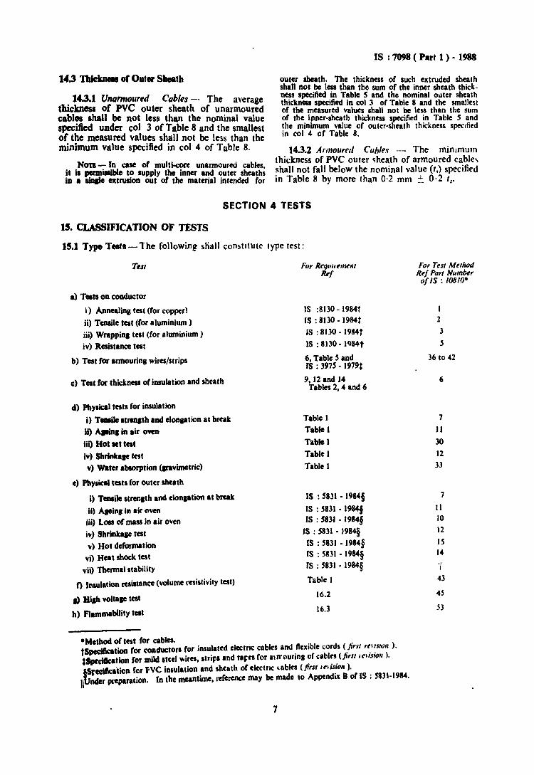
outer sheath. The thickness of such extruded sheathshall not be less than the sum of the inner sheath thickness specified in Table S and the nominal outer sheaththickness specified in col 3 of Table 8 and the smallestof the measured values shan not be less than the sumof the. ipner-sheath thickness specified in Table Sandthe mlnamum value of outer-sheath thickness speofiedin col 4 of Table 8.
14.3.% Armoured CUbles - The minimumNOD-In case of multkore unarmoured cables thickness of PVC outer sheath of armoured cabJe~
it ia ~ialible to supply the inner and outer sheath~ shall not fall below the nominal value (I,) specifiedin a sinale extrusion out of the material intended for in Table 8 by more than 0·2 mm =. 0·2 Is·
14.3nk~ of Outer Sheath
14.3.1 Unarmoured Cables - The averagethickness of PVC outer sheath of unarmouredcabl. shall be not less than the nominal valuespecified under col 3 of Table8 and the smallestof the measured values shall not be less than theminimum value specified in col 4 of Table 8.
SECTION 4 TESTS
15. CLASSIFICATION OF TESTS
15.1 Type T.fl-lhe following shall constitute type test:
Tell Fo, Req""e,,,enlRt'f
ForTest MethodRef Pan Numberof IS : 108/0·
a) Testson conductor
i) Annealinl test (for copper)ii) TCIlIile test (foraluminium)iii) WrappiDI test (for aluminium)iv) Resistance test
b) Test for armourin, wires/strips
c) Test for thkknas of insulationand sheath
IS :8130 - 1984t
IS : 8130 • 1984tIS : 8130 - 1984tIS : 8130. lQ84t
6, Table s andIS : 397S • 1979:
9, 12 and J4Tables 2,4 and 6
I2J
S
36 to 42
6
d) Phyaical tests for insulation
l) Teasilc"reDlth and clonption at bRat
Ii) Allin,in air OWD
iii) Hot.t tetttv) Shrink_it testv) Waterabsorption(....vimetric)
e) Physical tests for outer sheath
i) Tcnaile strcnltb and clonlalion II break
ii) A,ein,In lir oveniii) Loss 01mass in air oveniv) Shrinkaaetat
v) Hot deformationvi) Hca1 shocktest
vii) Thermalstability
o Insulationresistance (volume resistivity test)
a) Biah voltaae test
h) Flammability telt
Table 1
Table I
Table ITable ITable 1
IS : S831 • 1984§
IS : 5831 • 1984fIS : 5831 - 1984§
IS : S831 - 1984§(S : S831 • 1984§rs : 5831 - 1984§rs : 5831 • 1984§
Table J
16.2
16.3
7
JI
30
12
33
7
It10
J2
IS14
'I43
4S
53
-Method of test for cables.fSpeciftcatioa for coaductors for insulated eleetnc cablesand flexible cords (first reusnn ).~Sprdk.tion lor mild stecl _ires, strips and tar:rafor 81rrourina of cables (first' "t ;5;011 ).
fSredtkatioft fer PVC il\Iulation and sh(ath of electne "ablfS (first "';S;OIl ).Jlbnder preparation. (0 the meantime, reference may be made to Appendix B of IS : 5831-1984.
7
IS : 11M ( Part I )•••
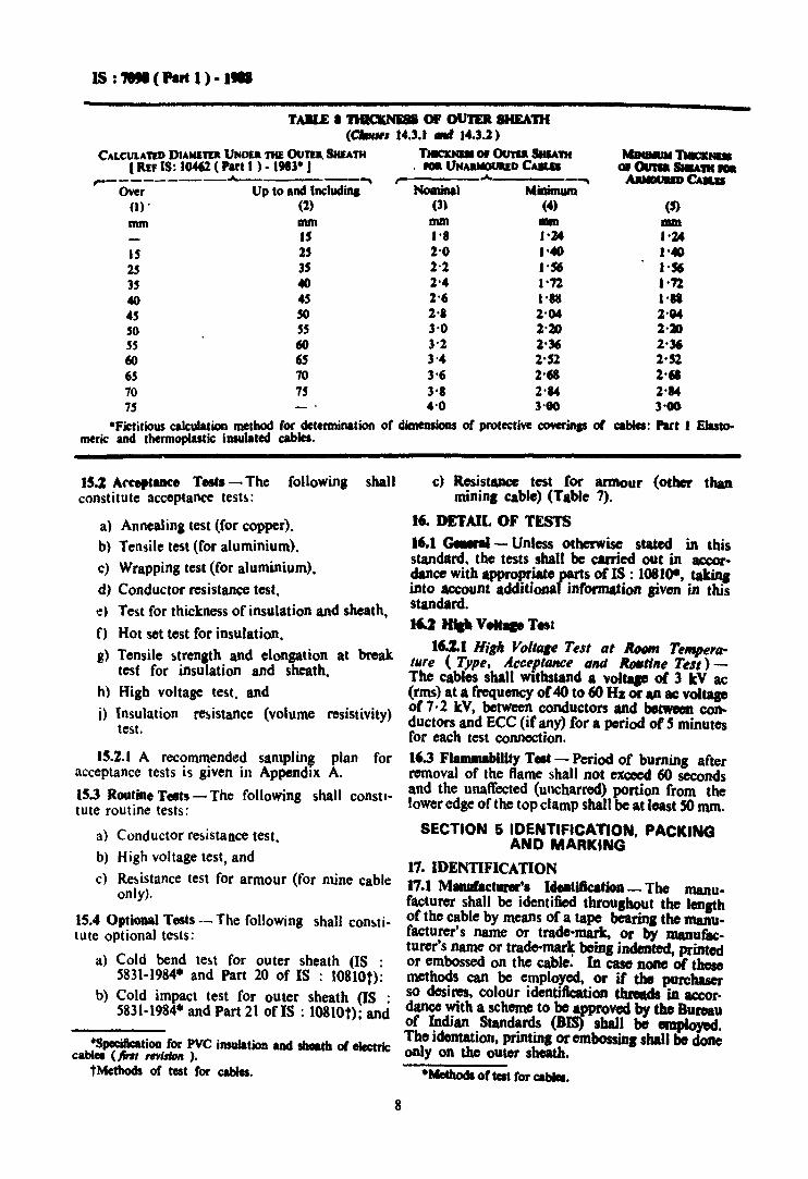
TABLE • TIIICItN& or OUTER SHEATH(C'IIrw, 14.3.1 ." 14.3.2)
CALCULATED DIAMI'I'P UNDO TIll OUTEa. SHEATH TlaatNIII or o.nu. SHlAm MINIMUM 1'Iac&NIa( RtF IS: 10462 ( Part I ) • 1913' J . lOa UNA&MOtIUD CAlLa Of 0U1U SHIA'III1IOIlr----------A-- ~ ~ ~ ~ ~a..
Over Up to and Includin. NomiDJi Minimum(I) . (1) (3) (4) (5)mm mm mm .. DUll
IS 1'8 1'24 1'24IS 25 2'0 I'" I'.25 35 2'2 1'$6 1'$635 40 1'4 I'n 1''7240 45 1'6 1'88 I'"45 SO 2'8 2'04 2'0450 55 3'0 2'20 2,2055 60 3'2 2'" 2'"60 6S 3'4 1'51 2'526S 70 3'6 2'" 2'.70 75 3'8 2·... 2·...75 4'0 3'00 ) .•
'Fictitious calculation method for determination of dimeasioDs of protective cowrinas 01 cables: Part I Elastomeric and thermoplastic illSulated cables.
15.2 Afceptance Tests - The following shallconstitute acceptance tests:
a) Annealing test (for copper),
b) Tensile test (for aluminium>,
c) Wrappina test (for aluminium).
d) Conductor resistance test,
e) Test for thickness of insulation and sheath,
n Hot set test for insulation.
g) Tensile ~trength and elongation at breaktest for insulation and sheath.
h) Hiab voltage test, and
i) Insulation resistance (volume resistivity)test.
15.2.1 A recommended samplin$ plan foracceptance tests is given in Appendix A.
IS.3 Routine Tests - The following shall constitute routine tests:
a) Conductor resistance test.
b) High voltage test, and
c) Resistance test for armour (for mine cableonly).
IS.4 OptiODllI Tests -- The following shall constitute optional tests:
a) Cold bend test for outer sheath (IS :5831-1984* and Part 20 of IS : 10810t):
b) Cold impact test for outer sheath (IS :5831·1984· and Part 21 of IS : 10810t); and
·Specification for PVC insulation aad sheath 01 eIcctric:cablea (fin, ,.rilltJn ).
tMethods or test for cables.
8
c) Resistance tcst for armour (other thanminin, cable) (Table 7).
.6. DETAIL OF TESTS
16.1 GeMraI- Unless otherwise stated in thisstandard. the tests shall be carried out in accordance with appropriate parts of IS : 10810-, takinainto account additionaT information ,iven in thisstandard.
16.2 IftIIl V...... Test
16.2.1 High Yo/I.e Test at Room TeMperature (Type, Acceptance lind RoMti"e Tell)The cables shall withstand a voitaF of 3 tV ac(rms) at a frequency or40 to 60 Hz or an Ie voitaFof 7·2 kV, between conductors and betwen conductors and ECC (if any) for a period of S minutesfor each test connection.
16.3 FlammabUlty T.t - Period of bumin, afterremoval of the flame shall not exceed 60 secondsand the unaffected (uncharred) portion from thelower edge of the top clamp shall be at least SO mm.
SECTION 5 IDENTIFICATION, PACKINGAND MARKING
17. IDENTIFICATION17.1 Manufacturer'. ldea.iftcatioa- The manufacturer shall be identified tbrou,hout the lenlthof the cable by means of a tape bearin, the manufacturer's name or trade-mark, or by manufacturer's name or trade-marlf bein, indented, printedor embossed on the cable. In case none of thosemethods can be employed, or if the purchaserso desires, colour identification thNads in accor.dance with a scheme to be approved by thoBureauof Indian Standards (DIS} shall be employed.Tho idontatiOJI, printin, or embossinc shall bedoneonly on the outer sheath.
·Method. 01tat for ca....
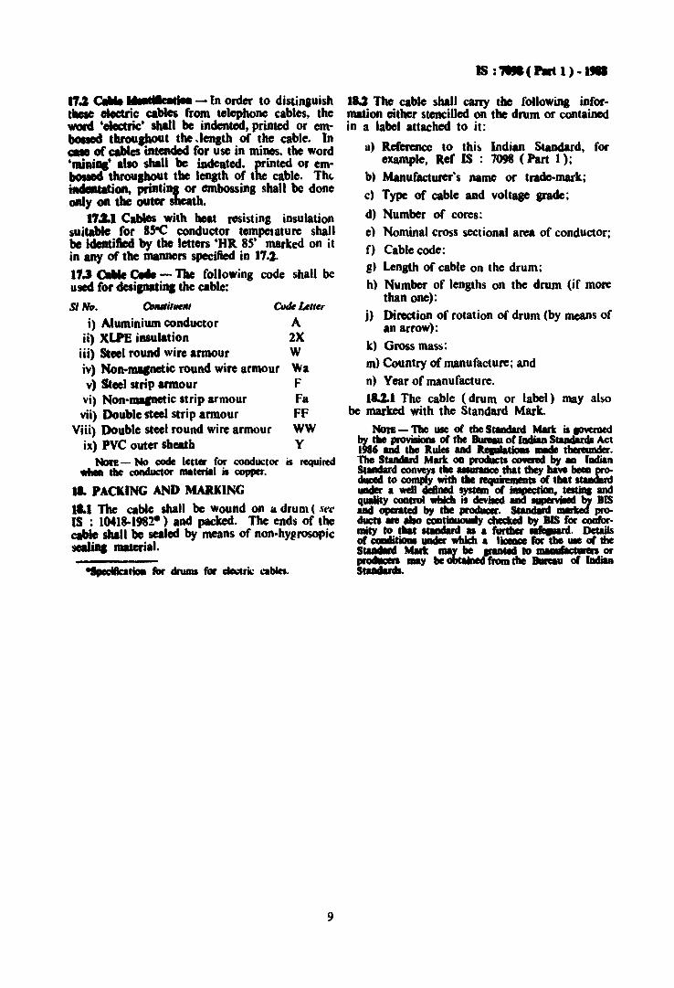
•1.2 CIIIIe - In order to distin.ui5hthese oIoctric cables from telephone cables. thewont 'oloctri<:' shall be indented. printed or embossed throuput the .length of the table. Incall or cables iDteftdod for use in minos. the word'mini..' also shall be iadeatcd. printed or embouIDd throughout the len81h of the cable. Th"i......tion. printin, or embossing shall be doneonly on the outer sheath.
1'7.1.1 Cables with beat resisting insulationsuitable for 85-e conductor tempelature shallbe identified by the letters 'HR 8S' marked on itin any of the manners specified in 17.2.11.3 CallIe~ - The following code shall beused for clesipati.., the table:
SI No. OnutilNeIlt Code Uller
i) Aluminium conductor Aii) XLPE insulation 2X
iii) Steel round wire armour Wiv) Non-mapetic round wire armour Wav) Steel strip armour F
vi) Non-macnetic strip armour Favii) Double steel strip armour FF
Viii) Double steel round wire armour WWix) PVC outer sheath Y
Non - No code lccter for c:ood~lor is required.... the conductor material is copper.
.1. PACKING AND MARliNG
.1.. The able shall be wound on a drum ( seeIS : 1041S.198~) and packed. The ends of thecable shall be sealed by means of non-hy@rosopicseaIiDa lMterial.
......tioII tor drums for _ ..ril: ca....
9
IS :,.( PIIt 1) •••
IU The cable shall carry the following information either stencilled on the drum or containedin a label attached to it:
a) Reforencc to thi~ Indian Standard. forexample, Ref IS : 7098 (Part I);
b) Manufacturer's name or trade-mark;
c) Type of cable and voltage grade;
d) Number of cores:
e) Nominal cross sectional area of conductor;
f) Cable code:g) Length of cable on the drum;
h) Number of lengths on the drum (if morethan one):
j) Direction of rotation of drum (by means ofan arrow):
k) Gross mass:m) Country of manufacture; and
n) Year of manufacture.
lUI The cable (drum or label) may alsobe marked with the Standard Mark.
NorB- The use of the StlDdard Mark is~by tho provisions of the Buroau of I8dian Studards Act1986 and the Rules and 1lcauIatioal IIIIde thereunder.The StaDdlnl Mart oa prodUcts COWNd by aD IndianStandard COR\'C)'I the UIUl'IIICe that they bPe been pr0duced to comply with the requiremeftcs of tbat ItaDdardunder • well defined System of iDIDecCion. teItiDI andquality control which is de¥iIed aaa ..."... by BIS_ operated by the producer. StaadInI marIraf pr0-ducts ale also COGtiauoully checUd by BIS for ClOIIIormity to tbar studlrcl •• furtbcl'~. Detailsof CoalIitioal under which. licaa for tho use of theS...... Mark ., be ~ted to -m6ctwen or...... .y be obtained from the Bureau of IDdianS........
IS : '7091 ( Part 1 ) •1-
APPENDIX A(Clause 15.2.1)
SAMPLING 0.: CABLES
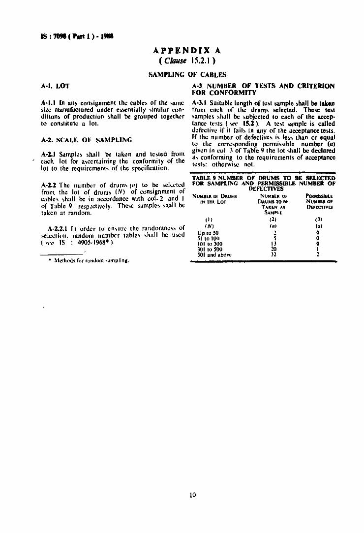
A-I. LOT A-3. NUMBER OF l·ESTS AND CRITERION"·OR CONFORMITY
A-I.I In any consignment the cables or the same A-J.I Suitable length of test sample shall be takensize manufactured under essentially similar con- from each of the drums selected. These testdition~ of production shall be grouped together samples shall be subjected to each of the aecepto constitute a lot. lance tests (~t'(~ 15.2). A test sample is called
defective if it rail~ in any of the acceptance tests.A-1. SCALE 01: SAMPLII'G rr the number of defectives i~ less than or equal
to the corresponding permissible number (tI)giv~n in col .1 of Table 9 the lot shall be declared
A-1.J Samples shall be taken and tested from a, conforming to the requirements of acceptance.. each lot for ascertaining the conformity of the tests: otherwise not.
lot to the requirement, of the specification.
(3)
(u)oooI2
PERMISSIBLENUMBER OFOEfECTIV[S
S132032
( I )(N)
Up to SOSI to 100101 to 300301 to SOOSOl and above
TABLE 9 NUMBER OF DRUMS TO BE SELECTEDFOR SAMPLING AND PERMISSIBLE NUMBER OF
DEFECTIVESNUMBt.R Ot
DRUMS TO 81:.TAKEN AS
SAMPLI::
(2)(n)
2
NUMBtR 01 DRUMSIN THI. LOT
• Methods for rundom ,alnpling.
A-Z.Z The number of drum (II) to be seh..ctedfrom the lot of drums (N) of consignment ofcables shall be in accordance with col..2 and Iof Table 9 respectively. These samples shall betaken at random.
A-Z.Z.I In order to en-ure the randomnc-s ofselection, random number table, shall be used(H'(' IS : 4905-1968-).
10

Bureauof Indian St.ndarda
BIS is a statutory Institution established under the Bureau of Indian Standards Act, 1986 to promoteharmonious development of theactivities ofstandardization, marking andquality certlftcatlon ofgoodeand attending to connected matters Inthecountry.
Copyright
BIS hasthe copyright of all its publications. Nopartof these publications maybe reprodUced In anyform without thepriorpermission Inwriting of 81S. Thisdoes notpreclude the freeuse, Inthecourse ofimplementing the standard, of necessary details, such as symbols andsizes, type or grade designations. Enquiries relating to copyright be addressed to the Director (PUblications). 81S.
Review of Indian Standard.
• Amendments are Issued to standards as the need arises on the basis of comments. Standards arealso reviewed periodically; a standard along with amendments Is reaffirmed when such review IndIcates thatno changes areneeded; If the review Indicates thatchanges are needed, It Is taken upforrevision. Users of Indian Standards should ascertain thatthey areIn possession of the late8t amendments or edition byreferring to the latest Issue of 'BISCatalogue' and'Standards: Monthly Additions'.
This Indian Standard hasbeendeveloped from Doc: No. ETD S9 (3087)
Amendmenta Issued Since Publication
Amend No. Date of Issue
BUREAU OFINDIAN STANDARDS
TextAffected
Headquarters :
Manak Bhavan. 9 Bahadur Shah lafar Marg, New Deihl 110 002Telephones: 23230131.23233375.23239402
Telegrams: Manaksanstha(Common to alloffices)
Southern : c.rr, Campus, IVCross Road, CHENNAI600 113
Regional Offices :
Central : Manak Bhavan, 9 Bahadur Shah zafarMargNEW DELHI 110002
Eastern : 1/14 e.I.T. Scheme VIIM,V. I. P. Road, KankurgachlKOLKATA 700054
Northern : SeQ 335-336, Sector 34-A, CHANDIGARH 160 022
Telephone
{2323 761723233841
{2337 8499, 2337 85812337 8626, 2337 9120
{80 3843609285
{2254 12~8, 2254 14422254 2519, 2254 2315
Western : Manakalaya, E9MIDe,Marol, Andherl (East) {2832 9295, 2832 7858MUMBAI 400093 2832 7891. 2832 7892
Branches: AHMEDABAD. BANGALORE. BHOPAL. BHUBANESHWAR. COIMBATORE. FARIDABAD.GHAZIABAD. GUWAHATI. HYDERABAD. JAIPUR. KANPUR. LUCKNOW. NAGPUR.NALAGARH. PATNA. PUNE. RAJKOT. THIRUVANANTHAPURAM. VISAKHAPATNAM.
Reprography Unit, 81S, New Delhi, Indie