is 7739-2 (1975): code of practice for preparation of...
TRANSCRIPT

Disclosure to Promote the Right To Information
Whereas the Parliament of India has set out to provide a practical regime of right to information for citizens to secure access to information under the control of public authorities, in order to promote transparency and accountability in the working of every public authority, and whereas the attached publication of the Bureau of Indian Standards is of particular interest to the public, particularly disadvantaged communities and those engaged in the pursuit of education and knowledge, the attached public safety standard is made available to promote the timely dissemination of this information in an accurate manner to the public.
इंटरनेट मानक
“!ान $ एक न' भारत का +नम-ण”Satyanarayan Gangaram Pitroda
“Invent a New India Using Knowledge”
“प0रा1 को छोड न' 5 तरफ”Jawaharlal Nehru
“Step Out From the Old to the New”
“जान1 का अ+धकार, जी1 का अ+धकार”Mazdoor Kisan Shakti Sangathan
“The Right to Information, The Right to Live”
“!ान एक ऐसा खजाना > जो कभी च0राया नहB जा सकता है”Bhartṛhari—Nītiśatakam
“Knowledge is such a treasure which cannot be stolen”
“Invent a New India Using Knowledge”
है”ह”ह
IS 7739-2 (1975): Code of Practice for Preparation ofMetallographic Specimens, Part 2: Electrolytic polishing[MTD 22: Metallography and Heat Treatment]

IS t 7739 (Part XI) - 1975
Indian Standard CODE OF PRACTICE FOR PREPARATION
OF METALLOGRAPHIC SPECIMENS PART II ELECTROLYTIC POLISHING
( First Reprint FEBRUARY 1988 )
UDC 620.182.253
Q Copyright 1976
BUREAU OF INDIAN STANDARDS hiANXK BHAVAN, 9 BAHADUR SHAH ZAFAR MARG
NEW DELHI 110002
Or 6 May 1976

IS s 7739 (Part II) - 1975
Indian Standard CODE OF PRACTICE FOR PREPARATION
OF METALLOGRAPHIC SPECIMENS PART II ELECTROLYTIC POLISHING
Metallography and Heat-Treatment Sectional Committee, SMDC 27
Chaimm Representing
SHRI K. V. CHINNAPPA International Nickel (India) Pvt Ltd, Bombay
Members
SURI M. ANJANEWLU Mining & Allied Machinery Corporation Ltd,
SHRI N. V. RAQHWAN (Alternate) Durgapur
SHRI N. C. BAOCHI SWR~ S. N. BANERJEE
National Test House, Calcutta
SHRI S. S. BHATNACAR Indian Institute of Metals, Calcutta National Metallurgical Laboratory (CSIR),
DR S. K. CHATTERJEE Jamshedpur
SHRI S. K. BA~U (Alternate) Guest, Keen, Williams Ltd, Howrah
SHRI DA~ARATHA The Mysore Iron & Steel Ltd, Bhadravati SHRI B. HARIDA~ACHAR (Alternate)
SHRI D. M. DAVAR SHRI A. T. BORATE (Altern&)
Premier Automobiles Ltd, Bombay
DEPUTY D I R E c T o R (MET-S), RDSO, LUCKNOW
Ministry of Railways
CHEMIST & METALLURGX~T (Alternate) SHRI A. K. GUHA Directorate General of Supplies & Disposals
SHRI P. C. MU~TAFI (Alternate) (Inspection Wing), New Delhi
SHRI H. A. JAISINGHANI SHRI A. R. RANADIVE (Altmna~e)
Mahindra & Mabindra Ltd, Bombay
SHRI M. L. KATYAL DR D. M. L.AKHIANI
Bajaj Auto Ltd, Pune
SHRI D. R. DA.SGUPTA (Alternab) Indian Iron & Steel Co Ltd, Burnpur
SHRX N. MAJUMDAR SHRI S. N. BOSE (Alfernafe)
Indian Aluminium Co Ltd, Calcutta
DR G. MUKHERJEE Hindustan Steel Ltd, Ranchi SHRI D. K. BAGCHI (Alternate)
(Continued on @ge 2)
BUREAU OF INDIAN STANDARDS
This publication is protected under the Indian CopVighht Act (XIV of 1957) and reproduction in whole or in part by any means except with written permission of the publisher shall be deemed to be an infringement of copyright under the said Act.

IS : 7739 (Part II) - 1975
(Cfmtinuefffhn page 1)
Members SHRI A. PADMANABHAN SHRr B. M. PAI
Re/wesenting Ashok Lcyland Ltd, Madras The Alloy Steel Producers’ Association of India,
Bombay SHRI S. A. hIALWADE (Alternate)
DR P. S. PATTIHAL Tata Engineering & Locomotive Co Ltd,
SHRI J. C. KAPOOR (Alternate) Jamshedpur
SHRI N. M. RAJU Hindustan Motors Ltd, Uttarpara SARI B. RAMA KRISHNA
SHRI J. NAGBSH BHAT (Alternate) Indian Telephone Industries Ltd, Bangalore
SHRI V. RAMA SWAMV Ministry of Defence (DGI), Department of Defence Production
SHRI R. H. G. RAU SHRI G. G. SAHA
M&and Iron & Steel Works Ltd, Bombay Ministry of Defence (R&D)
SHRI H. N. SINGH Textile Machinery Corporation Ltd, Belgharia DR L. R. VA~DYANATH
SHRI V. S. BHANDARY (Alternate) Indian Copper Information Centre, Calcutta
SHRI V. V. VIR~HADRAWA Directorate General of Technical Development. New Delhi
SHRI K. L. CHATTERJEE (Alternati) SHRI SUBHWH WADHAVAN Murarka Engineering Works, New Delhi SNRI C. R. RAMA RAO, Director General, BIS (Ex-oficio Member)
Director (Strut & Met)
Secretary SHRI B. MUKHERJI
Deputy Director (Met), BlS
2

IS : 7739 (Part II) - 1975
Indian Standard
CODE OF PRACTICE FOR PREPARATION OF METALLOGRAPHIC SPECIMENS
PART II ELECTROLYTIC POLISHING
0. FOREWORD
0.1 This Indian Standard (Part II) was adopted by the Indian Standards Institution on 20 October 1975, after the draft finalized by the Metallo- graphy and Heat Treatment Sectional Committee had been approved by the Structural and Metals Division Council.
0.2 Electropolishing is the preparation of smooth, scratch-free surfaces by anodic solution of a metal in an electrolytic bath. By correct adjustment of the composition of the electrolyte, temperature, voltage, current density, .and time, the removal of material from a metallic surface can be controlled SO as to affect mainly the protruding portions, leaving finally an approxi- mately plane surface suitable for metallographic observation.
0.3 The other parts of this code are as follows: Part I General features Part III Aluminium and its alloys and their examination Part IV Copper and its alloys and their examination Part V Iron and steel and their examination Part VI Lead and its alloys and their examination Part VII Magnesium and its alloys and their examination Part VIII Nickel and its alloys and their examination Part IX Gold, silver, platinum, palladium and their alloys Part X Tin and its alloys and their examination Part XI Zinc and its alloys and their examination
0.4 Some useful information regarding conditions of electropolishing and advantages and limitations of this process are given in Appendices A and B respectively.
0.5 In the preparation of this standard, assistance has been derived from ASTM E3-62 (1974) ‘Standard methods of preparation of metallographic specimens’ published by the American Society of Testing and Materials.
3
IS : 7739 (Part II) - 1975
0.6 In reporting the result of a test or analysis made in accordance with this standard, if the final value, observed or calculated, is to be rounded off, it shall be done in accordance with IS : 2-1960*.
1. SCOPE
1.1 This standard (Part II) covers electrolytic polishing of metal specimens for metallographic observation.
2. MECHANISM OF ELECTROLYTIC POLISHING 2.0 Recommended methods of selection, size, cutting, cleaning and mounting of metallographic specimens in IS : 7739 (Part I) - 19751. 2.1 The general mechanism of electrolytic polishing of a metallographic specimen is associated with dissolution of the specimen metal during anodic polarization of the specimen in a suitable electrolyte. The solution of the specimen metal during the process gives rise to the formation of a boundary layer of film of electrolyte immediately adjacent to the specimen surface that is of different composition and of higher electrical resistance than the remainder of the electrolyte. This layer of the boundary film is thinner at the protruding ridges of the ground surface, the concentration gradient is steeper, and the electrical resistance is lower, than that part of the boundary film associated with the valleys. As a consequence, under a given potential the current density at the peaks and ridges will be greater than at the valleys; and if the applied potential is sufficiently high, metal from the ridges will go into solution at a faster rate than metal from more depressed regions. “Ihis differential in the rates of dissolution causes a gradual smoothing out, or polishing, of the ground surface.
3. PREPARATION OF THE SPECIMEN SURFACE FOR ELECTROPOLISHLNG
3.1 The surface of the specimen to be electropolished shall be made plane by grinding on a series of emery papers or silicon carbide papers of decreas- ing grit size. For most metals and alloys, grinding through No. 000 emery paper is adequate preparation. After grinding, all debris shall be washed from the surface of the specimen and a fmal rinse shall be given with ether or other appropriate organic solvents to ensure complete removal of oily subs- tances that might otherwise interfere with uniform polishing. 3.2 Small specimens shall be mounted by conventional mounting procedures for ease in handling for mechanical preparation and subsequent electro- polishing. Electrical contact can be made through a small hole drilled through the back of the mount into the metal.
The possibility of violent reaction between plastics and certain electrolytes shall be taken into consideration, while mounting specimens in plastic.
*Rules for rounding off numerical values (reuked). tCode of practice for preparation of metallographic specimens: Part I General features.
4
IS : 7739 (Part II) - 1975
Mounting of specimens in dissimilar metals is not desirable because the metal in contact with the electrolyte is likely to interfere with polishing and also because fusible mounting alloys containing bismuth may be dangerously reactive in electrolytes containing oxidizing agents.
4. APPARATUS
4.1 For the electropolishing of metal specimens in appropriate electrolyte, a suitable electrolysis cell, and a controllable power supply are needed. Simple laboratory apparatus can be assembled to perform the function.
43 Whenever an attempt is made to polish large surface areas, the problems of obtaining sufficient current density and cooling of the specimen and elec- trolyte become very troublesome. An adequate mass of electrolyte should be used so that local overheating does not occur. may be required.
Supplementary cooling In general, electropolishing of areas larger than 1 cm2 is
not recommended for metallographic work because of the increased diffi- culties encountered, but it is usually possible to polish larger areas.
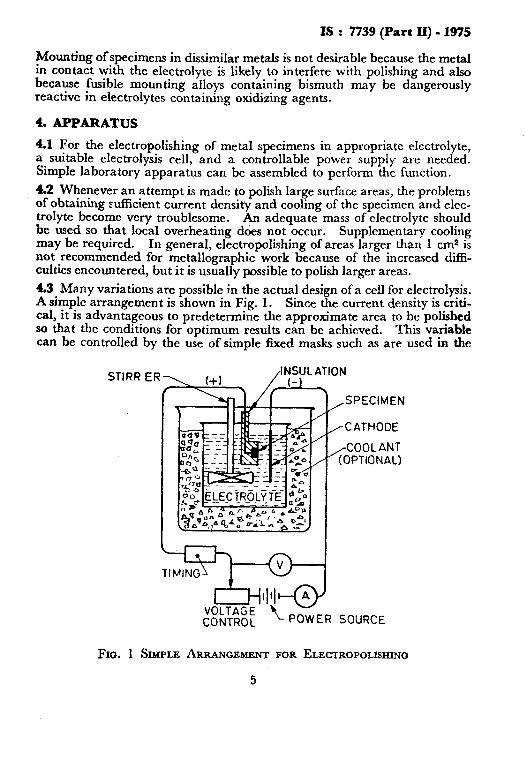
4.3 Many variations are possible in the actual design of a cell for electrolysis. A simple arrangement is shown in Fig. 1. Since the current density is criti- cal, it is advantageous to predetermine the approximate area to be polished SO that the conditions for optimum results can be achieved. This variable can be controlled by the use of simple fixed masks such as are used in the
STIRR ER>,(+) , /‘;:;‘,;,”
,SPECIMEN
1: /CATHODE
/COOL ANT (OPTIONAL)
VOLTAGE’ ‘< - CONTROL POWER SOURCE
Fm. 1 SIMPLE ARRANGEMENT FOR ELECTROPOLISHING

Is : 7739 (Part 11) - 1975 *
commercial apparatus, or by the use of protecting masks of insulating paints or tapes.
4.4 Suitable power sources may be batteries, rectifier power supplies, or direct-current generators. Since as much as 150 V may be required for the polishing of some meta.ls, precautions shall be taken to avoid electrical shock. The ideal power source would be a true direct-current potential with a closely controlled voltage. When ordinary line direct-current power is used, the voltage and current characteristics needed for electropolishing can be controlled only by the use of resistance. One of the best ways of obtaining the power for electropolishing is to rectify the output of a variable- voltage transformer (see Fig. 2). When a single-phase, full-wave, bridge- rectifier circuit is used, the output current is not satisfactory for all electro- polishing unless the ripple voltage is reduced to some small value by filtering. This is because a particular ionization level shall often be maintained withm close limits in the cell. Sufficient filtering for small amounts of power is obtained with small chokes and capacitors. When heavy currents are needed, a better source of power is a three-phase, full-wave, bridge recufier.
FILTER I-l- m
SINGLE PHASE FULL WAVE BRIDGE POWER SUPPLY
3 PHASE 1lOV OR 220V ac-
3PHASE FWB
3 PHASE POWER SUPPLY
Three variable voltage transformers ganged (star if 220 V, delta if I IO V).
FIG. 2 SCHEMATIC ARRANGEMENT FOR RECTIFYING ALTERNATING- CURRENT POWER SOURCE
6
IS : 7739 (Part II) - 1975
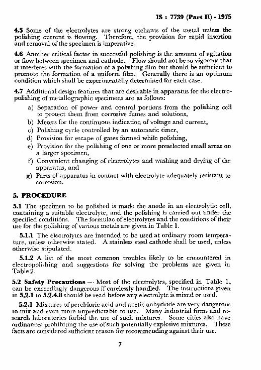
4.5 Some of the electrolytes are strong etchants of the metal unless the polishing current is flowing. Therefore, the provision for rapid insertion and removal of the specimen is imperative.
4.6 Another critical factor in successful polishing is the amount of agitation or flow between specimen and cathode. Flow should not be so vigorous that it interferes with the formation of a polishing film but should be sufficient to promote the formation of a uniform film. Generally there is an optimum condition which shall be experimentally determined for each case.
4.7 Additional design features that are desirable in apparatus for the electro- polishing of metallographic specimens are as follows:
a)
b) c) 4 e> f)
d
Separation of power and control portions from the polishing cell to protect them from corrosive fumes and solutions, Meters for the continuous indication of voltage and current, Polishing cycle controlled by an automatic timer, Provision for escape of gases formed while polishing, Provision for the polishing of one or more preselected small areas on a larger specimen, Convenient changing of electrolytes and washing and drying of the apparatus, and Parts of apparatus in contact with electrolyte adequately resistant to corrosion.
5. PROCEDURE
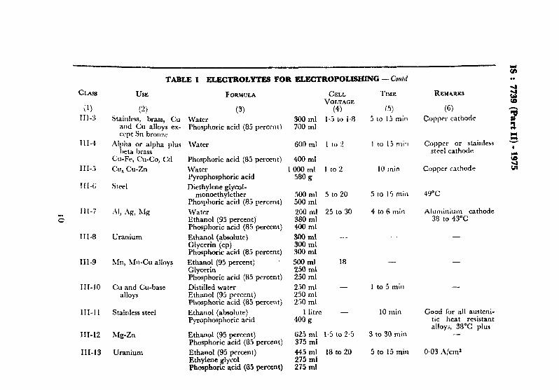
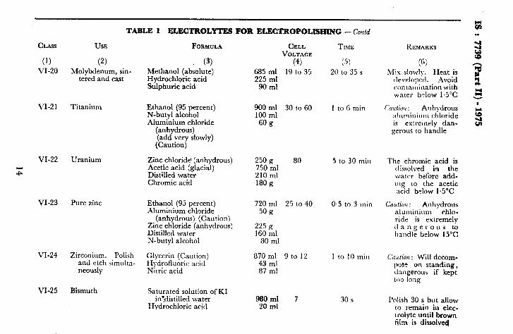
5.1 The specimen to be polished is made the anode in an electrolytic cell, containing a suitable electrolyte, and the polishing is carried out under the specified conditidns. The formulae of electrolytes and the conditions of their use for the polishing of various metals are given in Table 1.
5.1.1 The electrolytes are intended to be used at ordinary room tempera- ture, unless otherwise stated. A stainless steel cathode shall be used, unless otherwise stipulated.
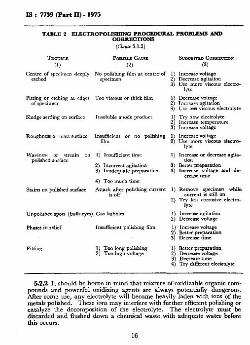
5.1.2 A list of the most common troubles likely to be encountered in electropolishing and suggestions for solving the problems are given in Table 2.
5.2 Safety Precautions -. Most of the electrolytes, specified in Table 1, can be exceedingly dangerous if carelessly handled. The instructions given in 5.2.1 to 5.2.4.8 should be read before any electrolyte is mixed or used.
5.2.1 Mixtures of perchloric acid and acetic anhydride are very dangerous to mix and even more unpredictable to use. Many industrial firms and re- search laboratories forbid the use of such mixtures. Some cities also have ordinances prohibiting the use of such potentially explosive mixtures. These facts are considered suXicient reason for recommending against their use.
7

CLASS
(1)
I-l
co I-2
I-3
I-4
I-5
I-6
I-7
TABLE 1 ELECTROLYTES FOR ELECTROPOIJSHXNG
(Chzzue~ 5.1 and 5.2)
USE FORMULA CELL TIME REMARKS VOLTAGE
(2) (3) (4) (5) (6) Group Z (Electrolytes Composed of Perchloric Acid and Alcohol With or HUhout Organic Additions)
Al and Al alloys with less than 2 percent Si
Steels-carbon, alloy, stainless Ph, Pb-Sn, Pb-Sn-Cd. Pb-Sn- SdSb Zn, Zn-Sn- Fe, Zn-Al-Cu Mg and high Mg alloys
Stainless steel and aluminium
Stainless steel
Ethanol (95 percent) Distilled water Perchloric acid (60 percent)
800 ml 30 to 80 140 ml 60 ml
35 to 65 12 to 35 20 to 63
15to6Os
-
-
15 to60s 15to6Os
-
-
Nickel cathode
Ethanol (95 percent) Perchloric acid (60 percent)
Ethanol (95 percent) Perchloric acid (65 percent)
Ethanol (95 percent)
800 ml 35 to 80 200 ml
940 ml 30 to45 60 ml
700 ml 30 to 65
15 to60s
15 to6Os
15 to 60 s
-
-
Steel, cast iron, Al and Al aIloys
Ni, Sn, Ag, Be, Ti, Zr, U, heat-resist- ing alloys
Steels-stainless, alloy, high-speed ; Fe, Al, Zr, Pb
Al, Al-Si alloys
MO, Ti, Zr, U-Zr alloy
P-Butoxy ethanol Perchloric acid (30 percent)
Ethanol (95 percent) Glycerin Pcrchloric acid (30 percent)
Ethanol (95 percent) Diethyl ether Perchloric acid (30 percent)
Methanol (absolute) 2-Butoxy ethanol Perchloric acid (60 percent)
100 ml - 200 ml
700 ml 15 to 50 100 ml
200 ml
760 ml 35 to 60 190 ml 50 ml
600 ml 60 to 150 370 ml
30 ml
-
15to60s
15 toG0s
5 to 30 s
One of the best for- mulae lor universal use
-_
Universal electrolyte comparable to I-4
Particularly good with Al-Si alloys
-

I-8
I-9
I-10
II-1
(0
II-2
II-3
II-4
11-5
III-1
III-2
AI-Si alloys Methanol (absolute) Glycerin Perchloric acid (65 percent)
Vanadium Methanol (absolute) 590 ml 30 Z-Butoxy ethanol 350 ml Perchloric acid (65 percent) 60 ml
Germanium Titanium Zirconium
-
Aluminium Methanol (absolute) Nitric acid Perchloric acid (60 perccnr)
‘5 lo 35 X to 6fi 70 Lo 75
950 ml 30 10 60 15 ml 50 ml
84Oml 50 to 100 125 ml
35 ml
5to6os
3s
30 to 60 s 45 s 15 i
ljlo6Os
Three-second cycles repeated at least seven times to pre- vent heating
Polish only Polish and etch simul-
taneously -
Group II (Electrolytes Grn#osed of Perchloric Acid a,ld Cl/aria1 :icetu Acid in Varying Proportions)
Cr, Ti, Zr, U
Fe, steel-carbon, alloy, stainless
Zr, Ti, U, stccl- carbon and alloy
U, Zr, Ti, Al, steel- carbon and alloy
Ni, Pb, Pb-Sb alloys
3 percent Si-Fc
Acetic acid (glacial)
Pcrchloric acid (60 percent)
Acetic acid (glacial) Perchloric acid (60 percent) Acetic acid (glacial) Perchloric acid (60 percent) Acetic acid (glacial) Perchloric acid (60 percent)
Acetic acid (glacial) Perchloric acid (60 percent)
9*0 ml
60 ml
900 ml 100 ml
800 ml 200 ml 700 ml 300 ml
650 ml 350 ml
“0 LO 60 1 to 5 min Good general pur- pose electrolyte
- - -
I:! to 70 0.5 Lo 2 min -
40 to 100 1 to 15 min -
40 to 100 1 to 5 min - t: . .
- 5 min 0.06 .\/cm? =: % -
Group III (Electrolytes Composed of Phosphoric Acid in IVuter or Otgauic Soluent) 2
Cobalt Phosphoric acid (85 percent) 1 000 ml 1.2 3 to 5 min x -
Pure copper DistilIed water 175 ml 1.0 to 1.6 10to4Omin Phosphoric acid (85 percent) 825 ml
Copper cathode 9 I
(Conlinwd) 5 . . .
_
cr.Ass
(1) III-3
III-4
III-5
III-G
III-7
z
III-8
III-9
III-10
111-l 1
III-12
III-13
TABLE1 ELJKXROLYTES PORELEGTROPOLISHING-Cotttd
USE FORMULA CELL VOLTAGE
(2) (3) (4) Stainlm. brass, Cu Water 300 ml 1.5 to 1.8
and Cu alloys ex- Phosphoric acid (85 percent) 700 ml ccpt Sn bronze
Alpha or alpha plus Water 600 ml I to :! beta brass
Cu-Fe, C&Co, <:rl
Cu,. Cu-Zn
Steel
Phosphoric acid (81 percent) 400 ml
Water 1 000 ml I to 2 580 g Pyrophosphoric acid
Diethylene glycol- monoethylcther
Phosphoric acid (85 percent)
Uranium
hfn, Ml-Cu alloys
Cu and Cu-base alloys
Stainless steel
Mg-Zn
Uranium
Water Ethanol (95 percent) Phosphoric acid (85 percent)
Ethanol (absolute) Glycerin (cpj Phosphoric acid (85 percent)
Ethanol (95 percent) ’ Glycerin Phosphoric acid (85 percent)
Distilled water Ethanol (95 percent) Phosphoric acid (85 percent)
Ethanol (absolute) Pyrophosphoric acid
Ethanol (95 percent) Phosphoric acid (85 percent)
Ethanol (95 percent) Ethylene glycol Phosphoric acid (85 percent)
500 ml St0 20 500 ml
200 ml 25 to 30 380 ml 400 ml
3OOml - 300 ml 300 ml
500 ml 18 250 ml 250 ml
250 ml - 250 ml 250 ml
1 litre - 400 g
if; In; 1.5 to 2.5
445 ml 18 to 20 275 ml 275 ml
TIME
(5)
5 to 15 min
I to 15 min
IO min
5 to IS min
4 to 6 min
-_
-
1 to 5 min
10 min
3 to 30 min
5 to 15 min
REMARKS
(G) Copper cathode
Copper or stainless steel cathode
Copper cathode
49°C
Aluminium cathode 38 to 43°C
-
-
-
Good for all austeni- tic heat resistant alloys, 38% plus
-
0.03 A/cm3

IV-1
IV-2
IV-3
Stainless steel
Stainless steel, Fe, Ni
Stainless steel, Fe, Ni, MO
IV-4 Molybdenum
IV-5 Stainless steel
I V-6 Stainless steel, alu- minium
E IV-7 Molybdenum
V-l
V-2
VI-1
VI-2
Stainlns steel
Zn, brass
Stainless steel
Staiuless steel
Group IV (Eiectrol~tes Composed of Sulphuric Acid in Water or Orgnnic Solvent)
Water Sulphuric acid
Water Sulphuric acid
Water Sulphuric acid
Water Sulphuric acid
250 ml I,.? to 6 750 ml
400 ml 1.5 to 6 600 ml
750 ml 1.5 to 6 250 ml
900 ml 1.3 to G 100 ml
Water Glycerin Sulphuric acid
Water Glycerin Sulphuric acid
Methanol (absolute) Sulphuric acid
70 ml 1.5 to 6 200 ml 720 ml
220 ml 1.j to 12 200 ml 580 ml
87.5 ml 6 to 18 125 ml
Group V (E!ectro(ytes Composed oj Ctuomic Acid in
Water Chromic acid
Water Chromic acid
830ml 1.i to9 620 g
830 ml 1.7 to 12 170 g
1 to 2 min
2 to 6 min
2 to 10 min hIo-0.3 to 1 min
0.3 to 2 min
0.5 to 5 min
1 to 20 min
0.5 to 1.5
IVater)
2 to 10 min
lOto60s
u’roup VI (dfixed Acids or Salts in TV&r or Orgwic .S’olutiou)
Phosphoric acid (85 percent) 600 ml - - Sulphuric acid 400 ml
Water 150 ml - 2 min Phosphoric acid (85 percent: 300 ml Sulphuric acid ix ml
-
Particularly good for s?ntercd MO, MO-O to 27°C
Particularly good for sintered MO, MO-O to 27°C
-
-
0 to 27°C

TABLE 1 ELECTROLYTES FOR ELECTROPOLISHING - Ci&
CL us
(‘1 \.I-3
Yl-4
\‘I-5
\‘I-6
;3 vi-7
\‘I-8
VI-9
‘\ I-10
VI-1 1
USE FORMULA
i2) (3) Stainless and alloy Water
steel Phosphoric acid (8; prrrmtj Sulphuric aciti
Stainless steel \Vatcr Phosphoric acid (8.5 prrccntj Sulphuric acitl
I~UIIIZC (to 9 percent Water Sll) Phosphoric acid (85 percent)
Sulphuric arid
Bronze (to G percent \Vatcr Sn)
Steel
Phosphoric acid (85 percent) Sulphuric acid \Vatcr Glycrrin Phosphoric acid (83 percent) Yulphuric acid
Stainless steel
Stainless steel
Stainless steel
St~~inss and alloy
\Vater Glycerin Phosphoric acid (85 percent) Sulphuric acid Water Chromic acid Phosphoric acid (85 percent) Snlphuric acid Water Chromic acid Phosphoric acid (85 percent) Sulphuric acid Water Chromic acid Phosphoric acid (85 percent) Sulphuric acid
240 ml 410 111 I 340 ml 330 ml 5iO ml 120 ml
450 ml 390 ml 160 ml
330 ml 580 ml
90 ml 140 ml 100 ml 430 ml 330 ml 200 ml 590 ml 100 ml 110 ml 260 ml
::5” Ll 580 ml 175 ml 105 g 460 ml 390 ml 240 ml
6:: frill 13OUll
CELL TIMI; ~OLTAGF.
(4) (j) - 2 to 10 min
- 1 mill
- 1 to j min
- 1 to 1 min
- 1 to 5 min
- 5 min
- 30 min
- 60 min
- 5 to 60 min
REMARKS
(tJI
0.1 to 0.2 .4/cm?
0.05 Ii/cm’
0.1 A/cm?
0.1 A/cm*
1 to 5 A/cm*, 38% PIUS
1 A/cma, 27 to 49’C
0.6 A/cm*, 27 to 49°C
0.5 A/cm’, 27 to 49°C
0.5 to A/cms,38 to 55%

VI-12 Tantalum
VI-13 Stain& btcel
VI-14 Zmc
VI-15 Stainless steel
VI-IG Stainless steel
w
\.I-17 Stainless atccl
\.I-18 Bismuth
VI-19 I2Iagnesium
Hydrofluoric acid 100ml - Sulphnric acid 900 ml
Water Hydrotluoric acid Sulphuric acid
Water Chromic arid Sulphuric acid Sodium dichromate Acetic acid (glacial)
Hydrogen peroxide (30 percent) (Caution)
Hydrofluoric acid Sulphuric acid
Water Hydrofluoric acid Sulphuric acid
Water Chromic acid Nitric acid Hydrochloric acid Sulphuric acid
Glycerin Acetic acid (glacial) Nitric acid
Ethylene glycol-monoethyl- ether
Hydrochloric acid
210ml - 180 ml 610 ml
800 ml - 100 g 46 ml
310 g 96 m[
260 ml -
240 ml 500 ml
520 ml a0 ml
400 ml
600 ml 180 g 60 g
3 ml 240 ml
750 ml 125 ml 123 ml
-
--
12
9 min Graphite, cathode, 0, I A/cma, 32 to 38%
5 min 0.5 A/cm?, 21 to 49%
- 0.00” .\/cm2, 2 1 to 38-C
5 min 0.5 A/cm”. Cn~ctig,n : Dangerous
l/2 to 4 min 0.08 to 0.3 A/cm*
-
1 to 5 min 0.5 &A/CUP. Caution: This mix- ture will decompose vigorously after a short time. Do not try to keep
900 ml 30 to 60 10 LO 30 5 Bath should be stir- 100 ml red. Go1 cracked
ice below 1.5”C
(Cdnued)
. / ,” ,, ,,,, ,., ” . ,,,>,, I ., ,/ ,, / .
CLASS
(1)
VI-20
\‘I-2 1
VI-22
z
VI-23
VI-24
VI-25
TABLE 1 ELEGTROLYTES FOR ELEGTROPOLISIimG -Cod
USE
(2) Molybdenum, sin-
tered and cast
Titanium
Uranium
Pure zinc
Zirconium. Polish and etch simulta- neously
Bismuth
FORMULA
(3) Methanol (absolute) Hydrochloric acid Sulphuric acid
Ethanol (95 percent) N-butyl alcohol Aluminium chloride
(anhydrous) (add very slowly) (Caution)
Zinc chloride’ (anhydrous) Acetic acid (glacial) Distilled water Chromic acid
Ethanol (95 percent) Aluminium chloride
(anhydrous) (Caution\ Zinc chloride (anhydrous) Distilled water N-butyl alcohol
Glycerin (Caution) Hydrofluoric acid Nitric acid
Saturated solution of RI in”distilled water
Hydiochloric acid
CELL VOLTAGE
(4) 685 ml 19 to 35 225 ml
90 ml
900 ml 30 to 60 100 ml
60 g
250 g 80 750 ml 210 ml 180 g
720 ml 25 to 40 50 g
225 g 160 ml
80 ml
870ml 9to 12 43 ml 87 ml
98Oml 7 20 ml
TIXIE
(5) 20 to 35 s
I to 6 min
5 lo 30 min
0.5 to 3 min
30 s
RIMARKS
(6) Mix slolvly. Heat is
developed. Avoid contaminationwith water lx~low I.j°C ‘
Cmtlion : Anhydrous aluminitlm chloride i< extremely dan- gerous to handle
The chromic acid is dissolved in the water before add- ing to the acetic acid below 1.5”C
Cautiojl : Anhydrous aluminium chlo- ride is extremely dangerous to handle below 15°C
Cclu/io,r : Will decom- pose on standing, dangerous if kept too long
Polish 30 s but allow to remain in elec- trolyte until brown fihq is dissolved

Croup VII (Alkaline lbctro~tes)
VII-1 Gold Water 1000 ml 7.5 Potassium cyanide Potassium carbonate z#f Gold chloride 5Og
VII-2 Silver Water 1OOOml 2.5 Sodium cyanide 1mg Potassium ferrocyanide 1mfz
VII-3 Silver Water IOOOml - Potassium cyanide Silver cyanide 2%; Potassium dichromate 280 g
VII-4 Tungsten Water 1OOOml - Trisodium phosphate 16Og
VII-5 Tungsten, lead Water 1000 ml -
zl Sodium hydrsxide 100 g
VII-6 Zinc, tin Water 1OOOml 2to6 Potassium hydroxide 2OOg
2 to 4 min
To 1 min
To 9 min
10 min
8 to 10 min
15 min
Croup VIII (Mixture of Mdhyl Alcohol and Nitric Acid)
VIII-l Ni, Cu, Zn, Monel, Methanol (absolute) 66Oml 40 to 70 10 to GO 5 brass, Nichrome, Nitric acid 330 ml Stainless steel
Graphite cathode
Graphite cathode
Gr;gi; cathode, to o+w9
A/cm’
Graphite cathode, 0.09 A/cm’, 38 to 49°C
Graphite cathode, 0.03 to O.OG A/cm2
Copper cathode, 0.1 to 0.2 A/cm”
z Very widely useful . . . .
Is : 7739 (Part ll) - 1975
TABLE 2 ELECTROPOLISHING PROCEDURAL PROBLEMS AND CORRECTIONS
(Clause 5.12)
TROUBLE PoSSIBLE CAUSE
(1) (2)
Centre of specimen deeply No polishing film at centre of 1) etched specimen 2)
3)
Pitting or etching at edges Too viscous or thick film 1) of specimen
:;
Sludge settling on surface Insoluble anode product 1)
:j
Roughness or matt surface Insucdent or no polishing 1) 2)
Waviness or streaks on 1) Insufficient time 1) polished surface
2) Incorrect agitation 2) 3) Inadequate preparation 3)
4) Too much time
Stains on polished surface Attack after polishing current 1) is off
2)
Unpolished spots (bulls eyes) Gas bubbles
Phases in relief Insufficient polishing film
:;
1)
s’,’
Pitting 1) Too long polishing 2) Too high voltage
SUGGESTED CORRECRON
(3)
Increase voltage Decrease agitation Use more viscous electro-
lyte
Decrease voltage Increase agitation USC less viscous electrolyte
Try new electrolyte Increase temperature Increase voltage
Increase voltage Use more viscous electro-
lyte
Increase or decrease agita- tion
Better preparation Increase voltage and de-
crease time
Remove specimen while current is still on
Try less corrosive lyte
Increase agitation Decrease voltage
Increase voltage Better preparation Decrease time
Better preparation Decrease voltage Decrease time Try different electrolyte
5.2.2 It should be borne in mind that mixture of oxidizable organic com- pounds and powerful oxidizing agents are always potentially dangerous. After some use, any’ electrolyte will become heavily laden with ions of the metals polished. These ions may interfere with further efficient polishing or catalyze the decomposition of the electrolyte. The electrolyte must be discarded and flushed down a chemical waste with adequate water before this occurs.
16

IS : 7739 (Part II) - 1975
5.2.3 Electrolytes, with few exceptions, should be mixed and stored in clean glass containers and never in contact with foreign or organic materials. They shall never be put aside and allowed to become concentrated by evaporation. Unless there is definite reason to do otherwise, ali electrolytes should be discarded as soon as they have passed their immediate usefulness.
5.2.4 The e’lectrolytes recommended for use are classified in.to eight . Their chemical components are listed in the order of mixing.
ZZZgh this is contrary to common practice, it is done to prevent possibly dangerous mistakes. Unless other instructions are given, the electrolytes are intended to be used in the ordinary room temperature range from 18 to about 32°C. The use of a stainless steel cathode is also presumed unless otherwise stipulated.
5.2.4.1 Group I (electrolytes composed of perchloric acid and alcohol with or without organic additions) - These electrolytes are believed to be safe to mix and use provided the following safety precautions are strictly observed:
a) The baths are only compounded in small quantities and are stored iI: glass stoppered bottles of such size that the bottles arc completeI: filled by the electrolytes.
b) Any evaporated solvents are promptly replaced by keeping the bottlc filled.
c) Spent or exhausted baths are promptly discarded. d) No departure is ever allowed from the prescribed formula, the
method of mixing it, or’ the strength of the acid used. e) The electrolytes are always protected from heat or fire.
5.2.4.2 Group II (electrolytes composed of perchloric acid and glacial acetic arid in uarying proportions) - Very little heat is developed when perchloric acid is mixed with glacial acetic acid. In mixing, the perchloric acid should be added to the acetic acid with stirring. These mixtures are supposed to bc per- fectly safe to mix and use but it is, nonetheless, felt that great care should be exercised with them. Temperatures shall never be allowed to exceed 30°C. They are flammable and shall be guarded against fire or the evaporation of the acetic acid. to such mixtures.
Plastic parts are likely to be quickly damaged by exposure
53.4.3 Group III (electrolytes composed of phosphoric acid in water or organic solvent) -These mixtures are generally quite easy to prepare. In mixing they are handled exactly as any mineral acid, namely, the acid shall be slowly poured into the water or solvent with constant stirring to prevent the forma- tion of a heavy layer of acid at the bottom of the vessel. Some solid phos- phoric acids are quite energetic in their combination with water.
5.2.4.4 Group IV (electrolytes composed of sulphuric acid in water or organic solvent) - The dilution of sulphuric acid with water is somewhat difficult due to the extremely exothermic reaction. The acid must always be poured into the water slowly and with constant stirring. Great care should be taken
17
I--- _-,--_ _________-.. ----
^--I-
IS : 7739 (Part II) - 1975
to prevent spattering. Even dilute solutions of sulphuric acid strongly a~ tack the skin or clothing. Such solutions are also very hygroscopic. vi,qorously attack most plastics.
They The mixtures of sulphuric acid with other
inorganic acids arc generally more useful as electrolytes.
5.2.4.5 Group I; (electro&tes romposed qf chromic acid in water) - The addi- ri{jn of crystailinc chromic acid to water is simple since very little heat is tl~~vclopcd. (:hromic acid is a polverful oxidant and under certain condi- tion\ it will liberate considerable quantities of free oxygen. It is generally dangerous and possibly incendiary in the presence of oxidizable materials. Tr cannot be safely mixed with most organic liquids. mixed with saturated organic acids.
It can generally be Chromic acid solutions cannot be
used in contact with plastic parts without their eventual destruction. Care should be taken to prevent its contact with the skin since repeated exposure to rven dilute solutions of chromic acid or the chromates will cause persistent and painful ulcers that are difficult to heal.
5.2.4.6 Group VI (mixed acids or salts in water or organic solutions) - These mixtures are safe to mix and use provided the mixing is properly done. It must be remembered that in all cases the acid is added to the solvent slowly and with constant stirring. If sulphuric acid is in the formula, it is added last and with particular care.
If hydrofluoric acid or fluorides are part of a formula, polyethylene or other similar hydrofluoric acid-resistant vessels should be used. Particular care should be taken to avoid skin contact with acid fluorides since exposure 10 them, which may pass unnoticed at the time, may result in serious burns later. In those electrolytes containing anhydrous aluminium chloride c.xtreme care must be exercised. The reaction between this compound and water is almost explosive. Chromic acid cannot b: safely mixed with most organic liquids but can be mixed with saturated organic acids. Care should be taken to prevent contact with the skin.
5.2.4.7 Group VII.(alkaline electrolytes) - These mixtures can b- groupzd in two general categories, those containing cyanide, and those not containing cyanide.
Caution - The use of cyanide by anyone not properly trained and familiar with it is cstrcmcly dangerous. Cyanides are among the quickest acting and most potent poisons likely to be encountered in the laboratory. Cyanide is so quick acting and deadly that the administration of an antidote is usually ineffectual. Extreme care must be taken that 110 droplet of the solution or crystal of the salt is ever left around where it can be acci- dentally picked up and carried to the mouth. Should any spillage occur, as much as possible should be mopped up with a sponge and water. The remainder can then be instantly drstroyed by washing the area with very dilute nitric acid.
Solutions of the alkali hydroxides are very useful for the polishing of certain amphoteric metals. Their attack on the skin is drastic, so great, care should be exercised in their use.
5.2.4.8 Group VIZI (mixture of methyl alcohol and nitric acid) - Nitric acid can be mixed with methanol wit’h apparent safety. This is done by adding
18
IS : 7739 (Part II) - 1975
the acid to the alcohol with careful stirring. It cannot safely be mixed with any higher alcohol except in very dilute solutions. If pure chemicals are used, the mixture of nitric acid and methanol is quite stable provided it is never heated or confined in any way. Do not store in a closed container. Under certain conditions, extremely unstable or explosive nitro compounds, azides or fulminates can be formed. The spontaneous decomposition of the mixture can also be catalyzed by impurities or heat. It should always be discarded as soon as it has served its immediate puspose. For certain cases this is an extremely useful electrolyte. Due to its dangerous nature, it should not be employed if its use can be avoided.
APPENDIX A
(Clause 0.4)
RECOMMENDATIONS FOR DETERMINING THE CONDITIONS OF ELECTROPOLISHING
A-I. Very frequently the metallographer is asked to electropolish some metal or alloy which he has not previously handled. There are several general principles which can be applied advantageously in these cases. The problem should be viewed in comparison with known procedures and information gained through previous experience. It is generally helpful to compare the position of the major component with elements of the same general group ,in the periodic arrangement of the elements, and to study the phase diagram, if available, to predict the number of phases and their characteristics. Single-phase alloys are generally easy to electropolish whereas multiphase alloys are likely to be difficult or impossible to polish. Minor alloying additions to the metal may profoundly affect its response to polishing in a given electrolyte.
A-2. The possibility of polishing a metal and the conditions for polishing a metal in a given electrolyte can sometimes be ascertained by plotting current versus voltage curves. The resulting curves will approximate one of the two forms shown in Fig. 3. Curve I is typical of electrolytes that polish over a very wide range or will not polish at all. Curve II is characteristic of electrolytes that form an ionic film. The dotted portion of the curve is added in recognition of certain published data and the observation that the formation of a polishing film requires finite time. Polishing will occur between B and C and is usually best at or slightly beyond C.
19

IS : 7739 (Part II) - 1975
<I CURVE IS OBSERVED - TYPICAL OF MINERAL ’ t’ ACID IN VISCOUS $! ORGANIC SOLUTION
x /
3 CURVE I OBSERVED * TYPICAL OF THE PERCHLO- I- RIC ACID-ALCOHOL
VOLTAGE CF.1 VOLTAGE (E)
FIG. 3 TYPICAL CURVES FOR DETERMINING CONDITIONS FOR ELECTROPOLISHING
A-3. After the polishing range is determined, the other constants, such as preparation, agitation and time can be determined experimentally. The amount of preparation depends on the nature of the specimen and on the results desired. Often this can be accomplished through the use of No. 0 emery paper on a powder grinder. In other cases it is necessary or desirable to have a good mechanical polish before starting to electropolish. The surface to be polished, should be clean in ail respects to obtain uniform attack.
A-4. To aid in selecting or developing an electrolyte for a new metal oralloy or to achieve-a specific result, a few characteristics that may be desirable in an electrolvte are listed below:
The electrolyte should generally be somewhat viscous. The electrolyte shall be a good solvent of the anode under electrolysis condi [ions. Insoluble products that form adherent deposits on the fact of the specimen may prevent polishing. It is desirable that the electrolyte does not attack the metal when-no current is flowing. This condition is not always achieved. The electrolyte usually should contain one or more ions of large radii, such as (10,)-s, (CIO,)-l or (SO,)-2 and sometimes large organic molecules. The electrolyte should be simple to mix, stable, and safe to handle. It is desirable that the electrolyte function at room temperature and not be sensitive to temperature changes, since it is difficult to control and maintain precise temperatures in an electrolyte during polishing.
20
IS : 7739 (Part II) - 197!j
APPENDIX B (Clause 0.4)
ADVANTAGES AND DISADVANTAGES OF ELECTROPOLISMNG
B-l. ADVANTAGES
B-l.1 When properly applied, electropolishing can be an extremely useful tool for the metallographer. The principal advantages of the method are as follows :
4
b)
s>
h)
3
For some metals, a high quality, finished surface can be produced that is equivalent to the best that can be obtained by mechanical methods.
Once a procedure has been established, good results can be obtained by even a new operator without the long training period so necessary to develop the physical skills for mechanical polishing.
There can be a marked saving of time if many specimens of the same material are to be polished sequentially.
The method is especially suited to the softer metals which may be difficult to polish by mechanical methods.
No scratches are produced in polishing.
Artifacts, such as disturbed metal or mechanical twins, produced on the surface even by careful grinding and polishing operations, should generally be removed. Thus, electropolishing may also be used to determine the true microstructure of a specimen as guide for mechanical preparation.
Surfaces resulting from electropolishing are completely unworked by the polishing procedures. This feature is important in low-load hardness testing or X-ray studies.
In some cases etching can be accomplished by simply reducing the voltage t.o approximately one-tenth the potential r~cquired for polishing and continuing electrolysis for a few seconds.
Electropolishing is frequently useful in electron metallography since the higher resolution puts a premium on clean, undistorted metal surfaces. It 1s sometlmes convenient to electropolish so as to leave a residual etch of suitable depth. The very clean, sligh t!y undercut surface may cause difficulties in replica stripping.
B-2. DISADVANTAGES
B-2.1 Metallographic preparation by electropolishing is subject to a number of limitations which should be recognized to prevent misapplication of the
21
Is : 7739 (Part II) - 1975
method and disappointment in the results. The principal disadvantages include the following:
I a) Manv of the chemical mixtures used in electropolishing are poison-
ous or dangerous if not properly handled. These hazards are similar to those involved in the mixing and handling of etchants.
b) The conditions and electrolytes required to obtain a satisfactorily polished surface are different for different alloys, hence considerable time may be required to develop a procedure for a new alloy, if it can be developed at all. This limitation does not apply if appro- priate procedures exist.
c) In multiphase alloys the rate of polishing of different phases may not be the same; at times this phenomenon may be an advantage.
d) A large number of electrolytes may be needed to polish the variety of metals encountered by a given laboratory.
ej Plastic or metal mounting materials may react with the electrolyte
f) Electropolished surfaces exhibit an undulating rather than a plane surface and may not in some cases be suited for examination at all
I magnifications.
g) Edge effects limit applications involving small samples, surface phenomena, coatings, interfaces, and cracks.
h) Attack around nonmetallic particles and adjacent metal, voids and various inhomogeneities may not be the same as that of the matrix, exaggerating the size of the voids and inclusions.
j) The electropolished surfaces of certain materials may be passive and difficult to etch.
k) Artifacts may occasionally be produced by electropolishing.
Headquarters :
Manak Bhavan, 9 Bahadur Shah Zafar Marg, NEW DELHI 110002
Telephones : 3 31 01 31.3 31 13 75 Telegrams : Manaksanstha
( Common to all Offices )
Regional Offices : Telephone
*Western ; Manakalaya, E9 MIDC, Marol, Andheri ( East ), 6 32 92 95 BOMBAY 400093
tEastern : l/14 C. I. T. Scheme VII M, V. I. P. Road, Maniktola, CALCUTTA 700054
Northern : SC0 445446, Sector 35-C CHANDIGARH 160036
Southern : C. I. T. Campus, MADRAS 600113
Branch Offices :
36 24 99
{ 23::::
I 41 24 42 41 25 19
l-41 29 16
Pushpak,’ Nurmohamed Shaikh Marg, Khanpur, AHMADABAD 380001
‘F’ Block, Unity Bldg. Narasimharaja Square, BANGALORE 560002
{ 2 63 48 2 63 49
22 48 05
Gangotri Complex. 5th Floor, Bhadbhada Road, T. T. Nagar. 6 27 16 BHOPAL 462003
Plot No. 82183, Lewis Road, BHUBANESHWAR 751002 5 36 27 6315 Ward No. 29, R. G. Barua Road.
5th Byelane. GUWAHATI 781003 -
5-8-56C L N. Gupta Marg. (Nampally Station Road), 22 10 83 HYDERABAD 500001
Rl4 Yudhistet Matg. C Scheme, JAlPUR 302005
{ 63471 6 98 32
117/418B Sarvodaya Nagat. KANPUR 208005
Patliputta Industrial Estate, PATNA 800013 Hantex Bldg ( 2nd Floor ). Rly Station Road,
TRIVANDRUM 695001
21 68 76 21 82 92
6 23 05 52 27
Inspection Office ( With Sale Point ):
Institution of Engineers ( India) Building. 1332 Shivaji Nagar, 5 24 35 PUNE 410005
l Saloa Office in Bombay ia at Novelty Chambera. Grant Road. Bombav 400007
89 66 28
tSaiea Of&; in Celcuttr ia at 5 Chowringhoe Approach. P. 0. Princep Street, Calcutta 700072
27 58 GO
Reprography Unit, BIS, New Delhi, India