is 9162 (1979): methods of tests for epoxy resins ...is i 9162 n 1979 indian standard methods of...
TRANSCRIPT

Disclosure to Promote the Right To Information
Whereas the Parliament of India has set out to provide a practical regime of right to information for citizens to secure access to information under the control of public authorities, in order to promote transparency and accountability in the working of every public authority, and whereas the attached publication of the Bureau of Indian Standards is of particular interest to the public, particularly disadvantaged communities and those engaged in the pursuit of education and knowledge, the attached public safety standard is made available to promote the timely dissemination of this information in an accurate manner to the public.
इंटरनेट मानक
“!ान $ एक न' भारत का +नम-ण”Satyanarayan Gangaram Pitroda
“Invent a New India Using Knowledge”
“प0रा1 को छोड न' 5 तरफ”Jawaharlal Nehru
“Step Out From the Old to the New”
“जान1 का अ+धकार, जी1 का अ+धकार”Mazdoor Kisan Shakti Sangathan
“The Right to Information, The Right to Live”
“!ान एक ऐसा खजाना > जो कभी च0राया नहB जा सकता है”Bhartṛhari—Nītiśatakam
“Knowledge is such a treasure which cannot be stolen”
“Invent a New India Using Knowledge”
है”ह”ह
IS 9162 (1979): Methods of Tests for Epoxy Resins,Hardeners and Epoxy Resin Compositions for Floor Topping[CED 5: Flooring, Wall Finishing and Roofing]


as I 9162 l 1919
Indian Standard METHODS OF TESTS FOR
EPOXY RESINS, HARDENERS AND EPOXY RESIN COMPOSITIONS FOR FLOOR TOPPING
Flooring and Plastering Sectional Committee, BDC 5
Chairman SHRI 0. P. MITTAL
Central Public Works Department, NewDelhi
Members Representing
SHRI E. T. ANTIA Concrete Association of India, Bombay SHRI M. G. DANDAVATE ( Alternate )
BRIG P. M. BHATIA Institution of Engineers ( India ), Calcutta SHRI A. K. BHATTACHAI~YYA National Test House, Calcutta
San1 G. C. DAS ( Alternate) SHRI DINESH A. CHOKSEII Arcoy Industries, Ahmadabad
SHRI RASII~LAL A. CHOKSHI ( Alternate ) DEPUTY DIRECTOR STANDARDS Ministry of Railways
( B & S ), RDSO, LUCKNOW DEPUTY D~RXCTOR ( ARCH ),
RDSO, Lucrr~ow ( Alternate ) DIIXIXTOR Maharashtra Engineering Research Institute,
Nasik RESEARCH OFFICER, MATE-
RIAL TESTING DIVISION (Alternate ) SIIRI K. V. GURUSWAMY Indian Oil Corporation Ltd, New Delhi
SNRI G. V. PANGARPER ( Alternate ‘, \ SHRI N. HAR~LAL Oxychloride Flooring Products Ltd, Bombay
SHRI H. J. VAKEEL ( Alternate) SHRI 0. K. KAPANI Builders’ Association of India, Bombay SHRI S. C. KAPOOR Modern Tiles & Marble, New Delhi
SHRI A. C. KAP~OR ( Alternate) SIIRI I<. E. S. MASI Bhor Industries Ltd,
SHRI RA~I~SH D. PATEL ( Alternate ) SHRI G. R. MIRCHANDANI Engineer-in-Chief’s
Defence )
Bombay
Branch ( Ministry of
( Continued on page 2 )
MAJ V. S. RAO (Alternate )
@ Copyright 1980
INDIAN STANDARDS INSTITUTION
This publication is protected under the Indian Copyright Act ( XIV of 1957 ) and reproduction in whole or in part by any means except with written permission of the publisher shall be deemed to be an infringement of copyright under the said Act.

IS t 9162 l 1979
( Continued from page
Members
1)
Representing
DR MOHAN RAI Central Building Research Institute, Roorkee ( Alternate ) DR R. K. JAIN
SHRI M. V. MURU~APPAN SHRI R. SRINIVASAN ( Alternate )
SHRI H. M. NANDKEOLYAR
SRRI K. P. SHAH ( Alternate) SHRI 0. P. RATRA REPRESENTATIVE
SHRI S. S. KAII~AL ( Alternate) REPRESENTATIVE SHRI D. B. SEN
Coromandel Prodorite Pvt Ltd, Madras
Indian Linoleums Ltd, 24 Parganas (West Bengal )
National Buildings Organization, New Delhi Bureau of Public Enterprises (Ministry of
Finance )
National Rubber Manufacturers’ Ltd, Calcutta Indian Institute of Architects, Bombay
SHRI S. B. SmnonrANY ( Alternate ) SUPERINTENDINR E N o I N x x R
( PLANNING Public Works Department, Government of Tamil
AND DESIGNS Nadu, Madras CIRCLE )
EXECUTIVE ENGINEER (BIJILDINU CENTRE DIVISION ) ( Alternate )
SUPERINTENDINO SURVEYOR OF Central Public Works Department, New Delhi WORKS ( ND2 )
SURVEYOR OF Weans I I NDZ 1 ( Alternate )
I
SHRI D. AJITBA SIMHA, Director ( Civ Engg )
Director General, IS1 ( Ex-oficio Member )
Secretary SHRI S. SENGUPTA
Assistant Director ( Civ Engg ), IS1
Panel for Epoxy Resin Floor, BDC 5 : P6
Convener
DR MOEAN RAI
Members
SHRI S. B. BAPAT SHRI R. S. LAAD ( Alternate )
SHRI G. R. MIRCHANDANI
CAPT S. C. KHANNA (Alternate) DR H. A. MONTEIRO SHRI C. S. PANT SHRI L. T. SHETH
Central Building Research Institute, Roorkee
Dr Beck and Co ( India ) Ltd, Pune
Engineer-in-Chief’s Branch Defence )
( Ministry ~Of
Ciba-Geigy of India Ltd, Bombay Central Road Research Institute, New Delhi Bakelite Hylam Ltd, New Delhi
SIIRI ti. K. SRINIVASAN ( Alternate ) SHRI R. S~INIVASAN Coromandel Prodorite Pvt Ltd, Madras
Sunr S. P. GULATI ( Alternate )
2
IS I 9162 n 1979
Indian Standard METHODS OF TESTS FOR
EPOXY RESINS, HARDENERS AND EPOXY RESIN COMPOSITIONS FOR FLOOR TOPPING
0. FOREWORD
0.1 This Indian Standard was adopted by the Indian Standards Institution on 22 March 1979, after the draft finalized by the Flooring and Plastering Sectional Committee had been approved by the Civil Engineering Division Council. 0.2 The epoxy resins are thermosetting resins and set to a hard mass with a suitable hardener. The compatibility of these resins with variety of hardeners have made these resins of multifunctional utility. Epoxy resin compositions are steadily finding increased use in the building industry on account of their qualities of adhesion and chemical resistance. They are suitable for use on industrial floors, such as in chemical plants manufacturing fertilizers, pharmaceuticals, acids and solvents, in dairies, tanneries, breweries, garages, service stations, airfields, warehouses, metal plating and pickling area, etc. The use of epoxy resin compositions for industrial floor topping is characterized by its exceptional physical and chemical properties, such as hardness, abrasion resistance, compressive, impact and flexural strengths, negligible shrinkage, dimensional stability and adhesion to cured concrete, metals and other surfaces,
0.3 Specifications for epoxy resins and epoxy resin compositions for floor toppings have been covered in IS : 9197-1979. This standard which covers the methods of tests for the determination of various characteristics of epoxy resins and their compositions for floor toppings is an essential adjunct to the above mentioned specification. 0.4 In the formulation of this standard due weightage has been given to international coordination among the standards and practices prevailing in different countries in addition to relating it to the practices in the field in this country. 0.5 In reporting the results of a test or analysis in accordance with this standard, if the final value, observed or calculated, is to be rounded off, it shall be done in accordance with IS : 2-1960*. n -__
*Rules for rounding off numerical values (revised).
3

IS t 9162 - 1979
1. SCOPE
1.1 This standard covers the methods for carrvine out the following tests e ”
on epoxy resins hardeners, and their compositions:
Test Clause Number
3
4
5
6
7
8
9
10 11
12
a) Amine number
b) Epoxy content c) Viscosity
d) Specific gravity e) Working time f ) Compressive strength g) Flexural strength and modulus of elasticity
h) Tensile strength
j ) Bond strength k) Linear shrinkage and coefficient of thermal
expansion m) Water absorption
n) Chemical resistance p) Abrasion resistance q) Thermal conductivity
r) Shear strength s) Hydrolyzable chlorine content of liquid
epoxy resin
2. TERMINOLOGY
13 14 15 16
17 18
2.0 For the purpose of this standard, the following definitions shall apply.
2.1 Amine Number - Indicates how many milligrams of potassium hydroxide are equivalent to 1 g of a hardener.
2.2 Epoxy Content - The measure of the reactive epoxy groups present in an epoxy resin and is generally expressed in terms of epoxy content per 1 000 g of the resin.
2.3 Hardener - Generally aliphatic amine, an aliphatic or aromatic amine adduct, polyamide or amido polyamines, etc, which react with epoxy resins at ambient temperature to give a cured thermostat resin product.
4
IS : 9162 - 1979
3. AMINE NUMBER
3.1 Object - To determine the amine number of a substance.
3.2 Chemicals and Reagents - The following reagent grade chemicals shall be used.
3.2.1 Hydrochloric Acid - 0.5 N.
3.2.2 Methyl Orange Indicator Solution
3.2.3 Solvent Ethylene Glycol, Isopropanol OY Butanol
3.3 Procedure - A blank determination shall be first carried out by titrating 50 ml of solvent mixture consisting of ethylene glycol and isopropanol or butanol in 1 : 1 ratio with 0.5 N hydrochloric acid using few drops of indicator solution.
3.3.1 About O-5 g of the substance is weighed to an accuracy of 0.2 mg into a conical Aask and dissolved in 50 ml of above mentioned solvent mixture. After adding a few drops of indicator solution, the mixture is then titrated with 0.5 N hydrochloric acid until the colour changes from pale yellow to orange.
3.4 Calculation - The amine number is calculated according to the following equation:
Amine number = y x56*1xN
where V = consumption of 0.5 N hydrochloric acid in sample titration, B = consumption of 0.5 N hydrochloric acid in blank titration,
M= mass of the substance, and
.7V = normality of O-5 N hydrochloric acid.
3.5 Alternate Method for Determination of Amine Number
3.5.1 Pt;inciple - The amine alkalinity of the sample is titrated potentiometrically with standard perchloric acid.
3.5.2 Material and Equipment
3.5.2.1 pH meter - equipped with external electrodes and having a sensitivity capable of f ( O-05 ) PH unit readings or similar potentiometric titrator.
a) Calomel electrode - sleeve type, silicone rubber sleeve, range 5 to 100°C.
b) Glass electrode - range 5 to 1OO’C.
5

IS : 9162 l 1979
3.5.2.2 Magnetic stirrer - with tetrafluoro-ethylene coated stirring bar.
3.5.2.3 Acetic anhydride - ACS grade ( AR ).
3.5.2.4 Nitrobenzene - melting point 5 to 6°C. Eastman 387 or equivalent ( AR ).
3.5.2.5 Acid potassium phthalate - N.B.S. primary standard ( AR ).
3.5.2.6 Glacial acetic acid - ACS grade (AR ).
3.5.2.7 Berzelins - tall form, 200 ml.
3.5.2.8 Perchloric acid in glacial acetic acid ( AR ) ( 0.1 N) -Add 28.4 g of perchloric acid ( ACS grade, 70 to 72 percent ) to 1 000 ml of glacial acetic acid in a 2 OOO-ml beaker. While stirring carefully add 46.6 g of acetic anhydride. Carefully pour the solution through a glass funnel into a 2 OOO-ml volumetric~flask and dilute to mark with glacial acetic acid. Mix the solution and allow to stand for 24 hours before standardizing.
3.5.3 Standardization - Weigh 0.31 to O-39 g of finely ground and dried acid’potassium phthalate into a 25%ml beaker on an analytical balance. Add 50 ml glacial acetic acid and warm gently to dissolve the samp!e. Cool and add an additional 50 ml of glacial acetic acid to wash down the sides of the beaker. Insert a stirriyg bar into the beaker and titrate while stirring with perchloric acid solution, using millivolt scale. Record the millivolt readitgs to every millilitre, but in the vicinity of the end point, record the milhvolt readings to every 0.1 millilitre. Plot a graph, showing the millivolt readings against the millilitres required for titration. The end point is the mid-point of the inflection on the titration curve. The strength of the perchloric acid is expressed in terms of its normality.
Perchloric acid ( N ) = Acid potassium phthalate (g ) x 4,896 7
Perchloric acid solution (ml )
3.5.4 Procedure
3.5.4.1 Weigh the approximate amount of well mixed resin to give a titration in the range of l-2 to 18 ml into a tared 200-ml berzelin tall form beaker on an analytical balance. Cover the beaker with aluminium foil to minimize contact with air.
3.5.4.2 From a graduated cylinder, carefully add 90 ml of nitro- benzene, insert a stirring bar, cover the beaker with foil and stir on a magnetic stirrer to dissolve the sample. Add nitrobenzene immediately after weighing the sample. Nitrobenzene is highly toxic and a fume hood should be used for all operations.
6
IS : 9162 - 1979
3.5.4.3 From a graduated cylinder add 20 ml of acetic acid to the sample solution and stir for several minutes.
3.5.4.4 Immerse the electrodes into the sample solution, stir for 2 minutes and titrate potentiometrically with 0.1 N perchloric acid using the millivolt scale. Record the millivolt readings to every millilitre, but in the vicinity of the end point record the millivolt reading to every 0.1 millilitre. Plot a graph showing the millivolt readings against milli- litres required for the titration. inflection on the titration curve.
The end point is the mid-point of the
3.5.4.5 Conduct a blank determination on 90 ml of nitrobenzene and 20 ml of acetic acid. The blank shall only be determined once for each lot of nitrobenzene used.
3.5.4.6 Calculation
Amine value = ( Sample titration - Nitrobenzene blank ) NX 56.1
Mass of sample
4. EPOXY CONTENT
4.1 Object - To determine the epoxy content of epoxy resin.
4.2 Apparatus
4.2.1 Burette - Closed reservoir type. The burette tip should be fitted with a rubber stopper of proper size to fit the neck of the -Erlenmeyer flask and the stopper should have an additional small hole to permit escape of replaced air during titration.
4.2.2 Magnetic Stirrer - with adjustable speed.
4.2.3 Erlenmeyer Flask - 50 ml, 125 ml capacity.
4.2.4 Magnetic Stirring Bars - tetrafluoro-ethylene coated.
4.3 Chemicals and Reagents - The ~following reagent grade chemicals shall be used.
4.3.1 Chlorobenzene
4.3.2 Crystal Violet Indicator Solution - 0.1 percent solution of crystal violet in glacial acetic acid.
4.3.3 Glacial Acetic Acid
4.3.4 Hvdrozen Bromide, Anhydrous
4.3.5 Hydrogen Bromide in Acetic Acid ( 0.1 Jv) -It shall be prepared by bubbling anhydrous hydrogen bromide at a slow rate through glacial acetic acid until the desired normality is attained ( approximately 8 g of
7

IS : 9162 - 1979
hydrozen bromide per litre ), Standardization of ;the solution shall be done daily against 0.4 g of potassium acid phthalate accurately weighed and dissolved by gently heating in 10 ml of glacial acetic acid.
NOTE 1 - Normally hydrobromic acid 30 to 40 percent concentration in acetic acid is available. This can be used to prepare the above solution by dilution with glacial acetic acid as an alternate method to the bubbling anhydrous hydrogen bromide in glacial acetic acid.
NBTE 2 - The reagent of 0.1 N concentration has been specified, because as solution exceeding this concentration becomes progressively less stable,
4.3.6 Potassium Acid Phthalate - primary standard ( AR ).
4.4 Procedure - A quantity of the liquid epoxy resin that contains OS001 to 0.002 g equivalents of epoxy groups is weighed to the nearest milligram in an Erlenmeyer flask of 50 ml capacity. 10 ml chlorobenzene is added to the flask to bring the resin into solution. A tetrafluoro-ethylene coated magnetic stirring bar is put into the flask and allowed to swirl on the magnetic stirrer to effect complete solution of the resin sample in chlorobenzene. Four to six drops of crystal violet indicator solution are added to the flask and then the flask while placed on the magnetic stirrer is attached to the rubber stopper on the burette tip. The burette tip is lowered to a point above the solution and titration with hydrogen bromide solution is carried out to a blue-green end point with the magnetic stirrer rotating the flask at a moderate speed to avoid splashing. The titration is slowed down near the end point to allow ample time for the reaction to take place.
4.4.1 A blank determination on the reagents shall be made in an identical manner.
4.5 Calculation
4.5.1 Normality ( Jv) of hydrogen bromide in acetic acid is calculated as follows:
1000 A ’ 204.2 B
where
A = mass in g of potassium acid phthalate used, and
B = volume in ml of hydrogen bromide used.
4.5.2 Epoxy content in gram equivalents of epoxy groups per 1 000 g of resin is culculated as follows:
Epoxy content = JV( A --B) c
where .N = normality of the hydrogen bromide in acetic acid,
8

A=
B=
c=
is t 9i62 - 1939
volume in ml of hydrogen bromide solution used for titra- tion of the sample,
volume in ml of hydrogen bromide solution used for titra- tion of the blank, and
mass in g of sample used.
4.5.3 Weight per epoxy equivalent ( WPE) that is grams of resin containing 1 g equivalent of epoxy groups is calculated as follows:
4.6 Repeatability - The average difference between duplicate runs performed by the same analyst may approximate 0.7 percent of the epoxy content of the resin tested. Two such values should be considered if they differ by more than 6 percent.
4.7 Alternate Method of Determination of Epoxy Content of Epoxy Resin
4.7.1 Reagents - The following reagents shall be used.
4.7.1.1 Pyridinium chloride in pyridine O-2 JV - 16 ml concentrated hydrochloric acid per litre of pyridine.
4.7.1.2 Methanolic sodium hydroxide 0.5 .N - 20 g sodium hydroxide per litre.
4.7.1.3 Phenolphthalein indicator - 0.10 g phenolphthalein per 100 ml methyl alcohol.
4.7.1.4 Methyl alcohol - reagent grade,
4.7.2 Procedure
4.7.2.1 Place a weighed sample of epoxy compound ( 2 to 4 milli- equivalent) into a 200-ml round bottom flask. Pipette 25 ml of pyridinium chloride-pyridine solution in another ZOO-ml flask. This shall be used as blank throughout the procedure. Swirl the solution until all the sample has been dissolved, heating gently if necessary, in a heating mantle plus a magnetic stirrer. After the sample has dissolved, add a reflux condenser, and reflux and stir the solution for 25 minutes. After refluxing, cool the solution with the condenser in place. Add 50 ml of methyl alcohol through the reflux condenser and let drain. Remove the reflux condenser, add 15 drops of phenolphthalein indicator. Titrate with 0.5 N methanolic sodium hydroxide from a lo-ml burette to a pink end point.
9

IS : 9162- 1979
4.7.2.2 Calculations
Epoxy equivalent = 16 x Sample mass (g)
Oxirane oxygen in sample (g)
Grams of oxirane oxygen = ( A - B ) ( N) ( 0.016 ) in sample
where
A = volume in ml of sodium hydroxide for blank,
B = volume in ml of sodium hydroxide for sample,
.N = normality of sodium hydroxide, and
0.016 = milliequivalent in g of oxygen.
5. VISCOSITY
5.1 Object - This method covers the measurement of the viscosity of epoxy resins, other epoxidized compounds, modifiers, and diluents used in formulating epoxy systems, liquid curing agents that effect the hardening of epoxy resins, and epoxy resin-curing agent systems or mixtures.
5.1.1 The viscosity of other liquid materials, either clear or opaque, can be determined by this method.
5.1.2 While the method described is valid for viscosities between 0.1 and 2 000 Pa.s, the use of kinematic method of measurement is recom- mended for viscosities between 0 and 0.5 Pa.s.
NOTE - For unfilled systems, more precise results may be obtained by using a kinematic procedure for viscosities up to 50 Pa.s.
5.2 Apparatus
5.2.1 Viscometer - Brookfield model RVF or equivalent.
NOTE- This method is based on the use of a Brookfield viscometer. Any other comparable viscometer may be used, provided that the limitations and procedures specified by the manufacturer are followed. Any viscometer should be checked for accuracy against standard liquids covering the normal range of operation of the instrument. The time lapse between checks should not exceed 6 months. A defective instrument should be recalibrated before further use, preferably by the manufacturer of the instrument.
5.2.2 Bath -temperature controlled, controllable to f O* l”C, either oil or water type.
5.2.3 Thermometer - with 0.1% divisions.
5.2.4 Glass Beaker - 600 ml capacity.
10

IS t 9162 l 1979
5.3 Conditioning
5.3.1 The sample shall be covered and placed in a temperature- controlled bath at the test temperature for at least 4 hours prior to being tested, or for however, much longer time is needed for all parts of the sample to reach the test temperature within f O*l”C. This conditioning may be carried out in the beaker in which the measurements are to be made,
NOTE - If the sample is a reacting mixture, such as a mixture of a resin with a hardener or catalyst, the resin component and the hardener component shall be brought to the test temperature separately. When both components have reached the test temperature, the resin and hardener shall be combined by slow agitation with a stirring rod or mixing paddle, avoiding the stirring-in of air. Three minutes of careful mixing is usually sufficient to yield a uniform blend. Immediately after mixing is complete, the spindle and the guard shall be attached to the viscometer. Readings shall commence 1 minute after completion of mixing.
Greater precision in determining the viscosity of reacting system can be obtained by use of Gardener tubes in a constant temperature bath.
5.3.2 Periods of conditioning shorter than 4 hours may be used, if experience has shown results to be comparable to those obtained after 4 hours of conditioning. If shorter than 4 hours, the time of conditioning shall be shown in the report,
5.3.3 The spindle and guard shall be brought to the test temperature before testing begins.
5.4 Procedure
5.4.1 Using the Brookfield Viscometer model RVF, the procedure shall be as given in 5.4.1.1 to 5.4.1.8.
5.4.1.1 Place a 500 ml portion of the previously conditioned sample in the clean beaker.
5.4.1.2 Insert the recommended spindle and guard into the sample, taking care to avoid the trapping of air under the spindle plate ( see Table 1 ).
NOTE 1 -When the sample consists of a mixture of a liquid and a solid, for example, a filled resin, the solid material shall be uniformly dispersed throughout the liquid phase. If the sample is a mixture of liquids, for example, a mixture of a liquid resin and a liquid hardener, the liquids shall be thoroughly mixed, and the mixture shall be visibly free of stirred-in air before inserting the spindle and the guard.
NOTE 2 - Since the accuracy of the viscometer is greatest in the middle of the dial range, it may be desirable to change the speed setting or the spindle, or both, to obtain a better reading. In general, greater accuracy is obtained by reading RVF values only on the ‘ 100’ scale, and adjusting the Brookfield factor accordingly.

IS : 9162 l 1979
5.4.1.3 Start the viscometer 1 minute after completion of any mixing (see Note 1 ). Allow the spindle to rotate for 30 seconds. Stop the instrument through use of the clutch, and read the dial.
NOTE 1 - Place the container on a nonconducting surface. Do not hold it in the hand,. since heat may be transferred to or from the material being tested, thus affectmg the viscosity. If extreme accuracy is needed. the measurements may be made while the sample is in its container in the constant-temperature bath.
NOTE 2 -The level mounting of the viscometer on a rigid stand or equivalent, and the use of a height-adjusting platform for the sample container will be advantageous.
5.4.1.4 After recording the first reading, allow the spindle to rotate an additional three to four cycles, and take a second reading.
5.4.1.5 If the second reading agrees with the first, record this figure. If, however, the two readings differ, allow the spindle to rotate three or four more times, and read the value again. Continue this procedure for ten readings, or until a constant reading is obtained.
NOTE - If the sample is a reacting mixture, for example, a resin and a hardener, it will often be impractical or impossible to obtain constant reading. In this case, the first reading is generally the one to record, unless it is desired to conduct a time versus viscosity study of theteaction.
5.4.1.6 Convert the reading obtained from the dial to viscosity in Pascal seconds, in accordance with the conversion table in Table 1.
5.4.1.7 It is often of interest to determine the thixotropic character- istics of the sample under test. The viscosity is measured at different speeds, and a relationship is set up as the index of relative thixotropicity or so called thixotropic index. For example:
( Viscosity at speed 2 )/ = 80 Pa.s/20 Pa.s = 4 ( Viscosity at speed 20 )
The thixotropic index is 4.
5.4.1.8 For more extensive rheological studies, the use of a Helipath stand is recommended.
5.5 Report - The report shall include the following:
4 b) Cl 4 e) f ) 63 h)
Viscosity, in Pa.s; Spindle number; Speed of rotation; Temperature of the sample to the nearest O*l’C; Ambient temperature to the nearest 0*5”C; Thixotropic index (g); Time of mixing ( for reacting systems only ); and Time of conditioning ( if other than 4 hours ).
12
IS : 9162 - 1979
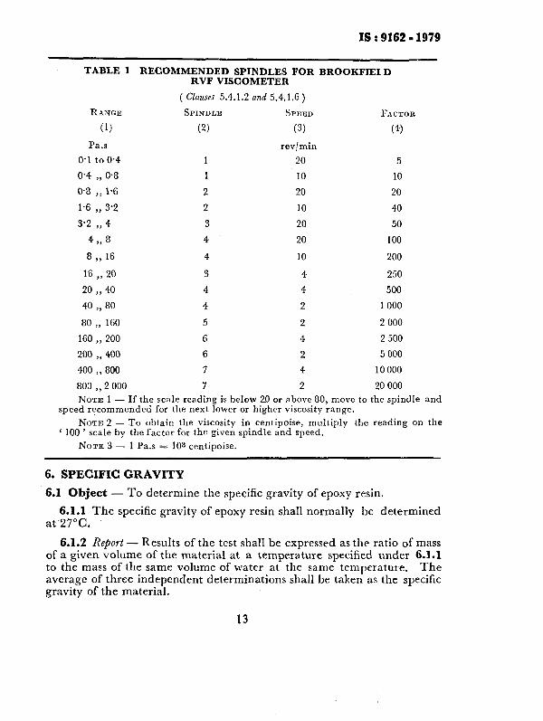
TABLE 1 RECOMMENDED SPINDLES FOR BROOKFIELD RVF VISCOMETER
( Clauses 5.4.1.2 nnd 5.4.1.6)
RANGE SPINDLE SPEEI) FACTOR
(1) (2) (3) (4)
Pa.s
0.1 to 0.4
0.4 ), 0.8
0.8 )) 1%
1.6 ,, 3.2
3.2 ,, 4
4 >, 8
8 >, 16
rev/min
20
10
20
10
20
20
10
5
10
20
40
50
100
200
16 20 ,, 3 4 250
20 )) 40 4 4 500
40 80 ,, 4 2 1000
80 ,, 160 5 2 2 000
160 ,, 200 6 4 2 500
200 400 ,, 6 2 5 000
400 ,, 800 7 4 10000
803 2 000 ,, 7 2 20 000
NOTE 1 - If the scale reading is below 20 or above 80, move to the spindle and speed rgcommended for the next lower or higher viscosity range.
NOTE: 2 - To obtain the viscosity in centipoise, multiply the reading on the ‘ 100 ’ scale by the factor for the given spindle and speed.
NOTE 3 - 1 Pa.s = 10s centipoise.
6. SPECIFIC GRAVITY
6.1 Object - To determine the specific gravity of epoxy resin.
6.1.1 The specific gravity of epoxy resin shall normally be determined at 27°C.
6.1.2 Report - Results of the test shall be expressed as the ratio of mass of a given volume of the material at a temperature specified under 6.1.1 to the mass of the same volume of water at the same temperature. The average of three independent determinations shall be taken as the specific gravity of the material.
13

IS : 9162 - 1979
6.1.3 Precision - Test results shall not differ from the mean by more than & 0.005.
6.2 Method
6.2.1 Apparatus - Specific gravity bottles of 50 ml capacity shall be used. One of the two types of specific gravity bottles, either (a) the ordinary capillary type specific gravity bottle with a neck of 6 mm diameter, or (b) the wide mouthed capillary type specific gravity bottle with a neck of 25 mm diameter shall be used.
6.2.2 Procedure - Clean, dry and weigh the specific gravity bottle together with the stopper. Fill it with freshly boiled distilled water up to
the brim and insert the stopper firmly. Keep the bottle for not less than 30 minutes in a beaker of distilled water maintained at a temperature of 27 5 O*l”C. Remove the bottle from the beaker, wipe all surplus moisture from the surface with a clean dry cloth and weigh again.
6.2.3 After weighing the water as mentioned in 6.2.2, empty the bottle and dry it. Fill it with the resin up to the brim and insert the stopper firmly. Keep the filled bottle for not less than 30 minutes in a beaker of distilled water maintained at a temperature of 27 & O*l”C. Remove the bottle from the beaker, wipe all surplus water from the surface with a clean dry cloth and weigh again.
6.2.4 Calculation - Calculate the specific gravity of the epoxy resin as follows:
Specific gravity = -i+
where
e = mass of the specific gravity bottle filled with epoxy resin,
a = mass of the specific gravity bottle, and
b = mass of the specific gravity bottle filled with distilled water.
6.2.5 Precautions - When making the specific gravity determination, it is important that:
a) only freshly boiled distilled water shall be used;
14

IS : 9162 - IL979
b) at no time of weighing shall the temperature of the apparatus be allowed to exceed the specified temperature;
c) precautions shall be taken to prevent expansion and over-flow of the contents resulting from the heat of the hand when wiping the surface of the apparatus;
d) all air bubbles shall be eliminated in filling the apparatus and inserting the stopper;
e) weighing shall be done quickly after filling the apparatus and shall be accurate to 0.1 mg; and
f ) to prevent breakage of the apparatus when cleaning after a deter- mination has been made, it is advisable to warm it in an oven at a temperature not above lOO”C, until most of the material is poured out and then to swab it with a piece of soft cloth or cotton waste. When cool, it may be finally rinsed with the solvent and wiped clean.
7. WORKING TIME
7.1 Object - To determine the working time of epoxy resin composition for floor topping.
7.2 Apparatus
7.2.1 Balance - of capacity 1 kg, sensitive to 0.1 g.
7.2.2 Mixing Pan - a porcelain enamelled pan measuring approxi- mately 400 x 250 x 50 mm deep.
7.2.3 Spatula - of stainless steel and about 25 mm wide.
7.2.4 Trowel - a mason’s triangular trowel.
7.3 Conditioning - All materials used in this test shall be stored at 27 & 2°C for at least 16 hours prior to use.
7.4 Preparation of Composition
7.4.1 Prepare 1 kg of the composition using proportionate amounts of filler and the liquid made of resin and hardeners, as recommended by the manufacturer. An appropriate amount of the liquid shall be poured into the mixing pan and the filler shall be gradually added to the liquid mixing thoroughly with the spatula or trowel. The mixing operation shall be continued for one minute to obtain a uniform mixture. Th.e total mixing time shall not exceed 4 minutes.
7.4.2 The mix now shall then be spread in a layer of uniform thick- ness covering the entire surface of the mixing pan.
15

38 : 9162 - 1979
7.5 Procedure - Remove approximately 15 g portions of the composi- tion mix at 5 minutes intervals and trowel on the horizontal surface of a clean dry brick or asbestos cement board. Consider the composition mix workable if it stays in the applied position, without curling behind the trowel while spreading. Do not return the material used for tests to the mixing pan.
7.6 Report - Record the working time as the time in minutes from the start of mixing the filler and liquid until the mortar ceases to be workable and fails to stay in the applied position while spreading.
8. COMPRESSIVE STRENGTH
8.1 Object - To determine the compressive strength of epoxy resin com- position for floor topping.
8.2 Apparatus - In addition to those given in 7.2.1 to 7.2.4 the follow- ing shall also be provided.
8.2.1 Moulds - The moulds shall be made of hard metal not attacked by the composition and shall be of the type capable of making three 50 mm cubes at one time. These shall be tight fitting and shall be separable into not more than two parts. The parts of the moulds when assembled shall be positively held together. The sides of the moulds shall be sulficiently rigid to prevent spreading or warping, The interior faces of the moulds shall be plane surfaces. The angle between adjacent interior faces and between interior faces and top and bottom planes of the mould shall be 90 f O-5”.
8.2.2 Compression Testing iklachine - universal type.
8.3 Composition Mix given in 7.4.
- The composition mix shall be prepared as
8.3.1 About 1 600 g of the composition mix shall be used from which six 50 mm cube specimens shall be prepared assuming that the mix density is not greater than 2.
8.4 Moulding of Test Specimens - Prepare at least six 50 mm cube specimens. Prior to filling the moulds, give their inner surfaces a thin coat of suitable material, such as silicon grease to prevent sticking of the com- position mix to the metal of the mould. Fill the moulds with the mix using the stainless steel spatula. Place approximately 30 g of the mix in the mould and work down using a vertical stroke with the spatula to prevent trapping of air in the specimen. When the moulds have been filled, strike
16
IS : 9162 - 1979
off the excess mix evenly with the top of the mould using an oscillating horizontal stroke of a straight edge.
8.5 Conditioning of Test Specimen - The test specimens shall remain in the respective moulds for a period of 24 hours after moulding.
8.5.1 Age the test specimens for a period of 7 days in air at 27 f 2°C.
8.6 Procedure - Test six cubes for compressive strength at the end of the ageing period. The compressive strength shall be the average of six cubes. The cubes shall be tested on their sides without any packing between the cube and the steel plattens of the testing machine. One of the plattens shall be carried on the base and shall be self-adjusting, and the load shall be steadily and uniformly applied, starting from zero at a rate of 35 N/mms per minute.
-NOTE - Cubes that are manifestly faulty shall not be considered. If any of the individual strength values of the specimen made from the same sample and tested at the same age differ by more than 15 percent from the average strength, or if fewer than four values were used in deriving the average strength, the test shall be repeated.
8.7 Report - The compressive strength shall be calculated from the crushing load and the average area over which the load is applied. Express the result in N/mm‘J.
9. FLEXURAL STRENGTH AND MODULUS OF ELASTICITY
9.1 Object
9.1.1 This method covers the measurement of the flexural strength and modulus of elasticity in flexure of epoxy resin composition for floor topping.
9.1.2 By this method flexural strength cannot be determined for those compositions that do not break.
9.2 Apparatus
9.2.1 Scales - The scales used in weighing materials for mortar -mixes shall conform to the following requirements:
a) On scales in use, the permissible variation at a load of 2 000 g shall be f 2 g.
b) On new scales the permissible variation at a load of 2 000 g shall be 1 g.
c) The sensibility reciprocal ( see Note ) shall not be greater than twice the permissible variation.
NOTE -Generally defined, the sensibility reciprocal is the change in load required to change the position of rest of the indicating element or elements on a non-automatic indicating scale by a definite amount at any load.
17

IS : 9162 - 1979
9.2.2 Weights - The permissible variations on weights in use in weighing materials for mixes shall be as prescribed in Table 2. The permissible variations on new weights shall be half of the values in Table 2.
TABLE 2 PERMISSIBLE VARIATIONS ON WEIGHTS
( Clauses 9.2.2 and 12.2.2)
WEICETS PERMISSIBLE VARIATIONS ON WEIGHTS IN USE
(1) EC
1000 900 750 500 300 250 200 100 50
20 10 5 2
(2) 6
+ 0.50 * 0.45 f 0.40 * 0.35 f 0.30 * 0.25 f 0.20 & 0.15 + 0.10 * o-05 rt 0.04 * 0.03
* 0.02 -+ 0.01
9.2.3 Equipment for mixing composition may consist of a container of suitable size preferably made of corrosion-resistant metal, or a porcelain pan, and a sturdy spatula or trowel.
9.2.4 Specimen Moulds - moulds permitting the moulding of bars of 25 x 25 mm and 250 mm long.
KOTE - Specimen length may be anything over 250 mm.
9.2.5 Testing Machine -- A properly calibrated testing machine which can be operated at constant rates of cross-head motion over the range indicated; and in which the error in the load measuring system shall not exceed -J= I.0 percent. It shall be equipped with a proper deflection measuring device.
9.2.6 Loading .Nose and Su@orts - The loading nose and supports shall have cylindrical surfaces. To avoid excessive indentation, the radius of the nose and supports shall be at least 3.2 mm for all specimens. The radius may be up to one and one-half times the specimen depth, and shall be large if significant indentation occurs.
18
IS : 9162 - 1979
9.3 Test Specimens ,
9.3.1 Temperature - The standard temperature of the mix constituents, mould, apparatus, and the temperature in the vicinity of the mixing operation shall be 27 f 2°C unless otherwise specified by the manu- facturer. The actual temperature shall be recorded,
9.3.2 Number of Specimens - A minimum of six test bar specimens shall be prepared for each composition mix.
9.3.3 Preparation of Mix
9.3.3.1 The mix shall be prepared in the proportions specified by the manufacturer. If the proportions so specified are by volume, the constituents shall be weighed and the corresponding proportions by mass shall be reported.
9.3.3.2 A standard batch size of 2 400 g of the mix shall be mixed, from which four bars of 25 x 25 x 250 mm (approximate ) shall be prepared.
9.3.4 Moulding Test Sfiecimens
9.3.4.1 Lubricate the mould by applying a thin film of mould release or lubricant in the inner surfaces.
9.3.4.2 Fill the mould with composition mix, taking care to eliminate air pockets by working the mix with a spatula or thin trowel. Level the top surface with the spatula and strike off the excess evenly.
9.4 Conditioning
9.4.1 The test specimens shall remain in their respective moulds for a period of 24 hours after moulding and under conditions described in 9.4.2.
9.4.2 All specimens shall be aged for 7 days in such a manner that air circulates on all sides at a temperature of 27 f 2°C and at a maximum relative humidity of 65 f 5 percent until tested.
9.5 Procedure
9.5.1 Test the bar specimens 7 days after preparation. If desired, the conditioning time may be lengthened or shortened to establish the age- strength relationship. Report the age of the specimens.
9.5.2 Place the specimen in the testing machine preset with a span of 229 & 2 mm and in such a manner that the faces of the bar that were in contact with the true plane surfaces of the mould are placed in contact with the surfaces of the loading nose and supports.
19
ISr9162-1979
9.5.3 Apply the load to the specimen at the rate of 4.2 N/mm% per minute and take simultaneous load-deflection data readings. Deflection shall be measured by either a gauge under the specimen and in contact with it at the centre of the span ( the gauge being mounted stationary relative to the specimen supports), or by measurement of the motion of the loading nose relative to the supports. Load-deflection curves may be plotted ( or made simultaneously if the machine is equipped with a recorder ) to determine the flexural strength ( modulus of rupture ), tangent modulus of elasticity.
9.5.4 If no break has occurred in the specimen by the time the maxi- mum stress and strain have been reached, the test shall be discontinued.
9.6 Calculations
9.6.1 Flexural Strength (_Modulus of Rupture ) - The flexural strength is equal to the maximum stress at the moment of crack nor break. It is calculated as follows:
S = 3PL/2bd=
where
S = stress in the specimen at mid span, N/mms;
P 5: load at the moment of crack or break, N;
L = span, mm;
b = width of beam tested, mm; and d = depth of beam tested, mm.
9.6.1.1 If the specimen does not break, the yield strength can be calculated in accordance with the above equation by letting P equal the maximum load attained on the stress-strain curve.
9.6.2 Modulus of Elasticity ( Tangent ) - The tangent modulus of elasti- city ( modulus of elasticity ) is the ratio, within the elastic limit, of stress corresponding to strain, and shall be expressed in N/mm? It is calculated by drawing a tangent to the steepest initial straight line portion of the load-deformation curve and calculating as follows:
where
E, = modulus of elasticity in bending, N/mmz;
L = span, mm;
20

fS t 9i62 -isi9
M = slope of the tangent to the initial straight-line portion of the load-deflection curve, N/mm of deflection;
b = width of beam tested, mm; and
d, - depth of beam tested, mm.
9.7 Report
9.7.1 The report shall include the following:
a> b) 4 d) 4 f >
Manufacturer’s name and details of composition,
Mixing ratio, Conditioning procedure,
Test conditions ( temperature and humidity ), Age of test specimen in days, and Individual and average results of flexural strength and modulus of elasticity.
9.7.2 Defective specimens shall be eliminated and the average results calculated on all remaining test specimens. If the individual values differ by more than 15 percent from the average, or if fewer than four values were used in deriving the average the test shall be repeated in exactly the same manner.
lo. TENSILE STRENGTH
10.1 Object - To determine the tensile strength of epoxy resin com- position for floor topping.
10.2 Apparatus -In addition to those given in 7.2.1 to 7.2.4 the following shall also be provided.
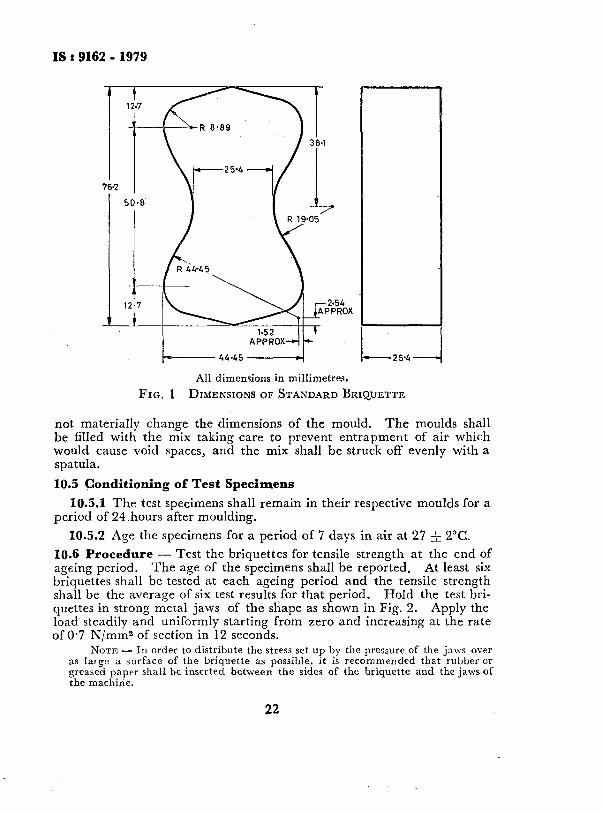
10.2.1 Moulds - The moulds shall be capable of producing briquettes of the shape shown in Fig. 1.
10.2.2 Testing Machine --The universal type testing machine in which load is applied at constant but adjustable rate.
10.3 Preparation of the Mix -The mix shall be mixed in the proper proportion and in the manner specified by the manufacturer.
10.3.1 At least 1 kg of the mix may be prepared from which six test specimens may be moulded assuming that the mix density is not greater than 2. Larger quantity will be required if the mix density exceeds 2.
10.4 Moulding Test Specimens - The moulds prior to filling shall be given a thin coat of suitable material, such as silicone grease to prevent sticking of the mix to the metal of the mould. Various materials may be used provided they do not interfere with the setting of the mix and do
21
IS:916291979
1 - 12.7
-25~4- b+------ 44.45 -4
All dimensions in millimetres.
FIG. 1 DIMENSIONS OF STANDARD BRIQUETTE
not materially change the dimensions of the mould. The moulds shall be filled with the mix taking care to prevent entrapment of air which would cause void spaces, and the mix shall be struck off evenly with a spatula.
10.5 Conditioning of Test Specimens
10.5.1 The test specimens shall remain in their respective moulds for a period of 24.hours after moulding.
10.5.2 Age the specimens for a period of 7 days in air at 27 f 2°C.
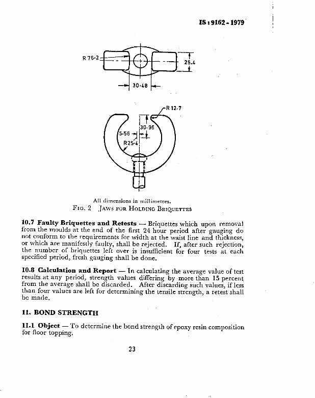
10.6 Procedure - Test the briquettes for tensile strength at the end of ageing period. The age of the specimens shall be reported. At least six briquettes shall be tested at each ageing period and the tensile strength shall be the average of six test results for that period. Hold the test bri- quettes in strong metal jaws of the shape as shown in %ig. 2. Apply the load steadily and uniformly starting from zero and increasing at the rate of 0.7 N/mm2 of section in 12 seconds.
NOTE - In order to distribute the stress set up by the pressure of the jaws over as large a surface of the briquette as possible, it is recommended that rubber or greased paper shall be inserted between the sides of the briquette and the jaws of the machine.
22
IS : 9162 - 3379 I
R 76.2
,-R12'
All dimensions in millimetres.
FIG. 2 JAWS FOR HOLDING BRIQUETTES
10.7 Faulty Briquettes and Retests - Briquettes which upon removal from the moulds at the end of the first 24 hour period after gauging do not conform to the requirements for width at the waist line and thickness, or which are manifestly faulty, shall be rejected. If, after such rejection, the number of briquettes left over is insufficient for four tests at each specified period, fresh gauging shall be done.
10.8 Calculation and Report - In calculating the average value of test results at any period, strength values differing by more than 15 percent from the average shall be discarded. After discarding such values, if less than four values are left for determining the tensile strength, a retest shall be made.
11. BOND STRENGTH
11.1 Object - To determine the bond strength of epoxy resin composition for floor topping.
23
18 8 9162 - 1979
11.2 Apparatus
11.2.1 Balance - of capacity 1 kg, sensitive to 0.1 g.
11.2.2 Testing Machine - Universal type in which the load is applied hydraulically, or mechanically or electromechanically at a constant, but adjustable rate of cross head movement or loading. The weighing system may be of the pendulum lever, beam or hydraulic type.
11.2.3 Mixing Pan - porcelain enamelled pan measuring 250 x 400 x 50 mm.
11.2.4 Trowel - bricklayers’ triangular trowel.
11.2.5 Guide - for marking tile.
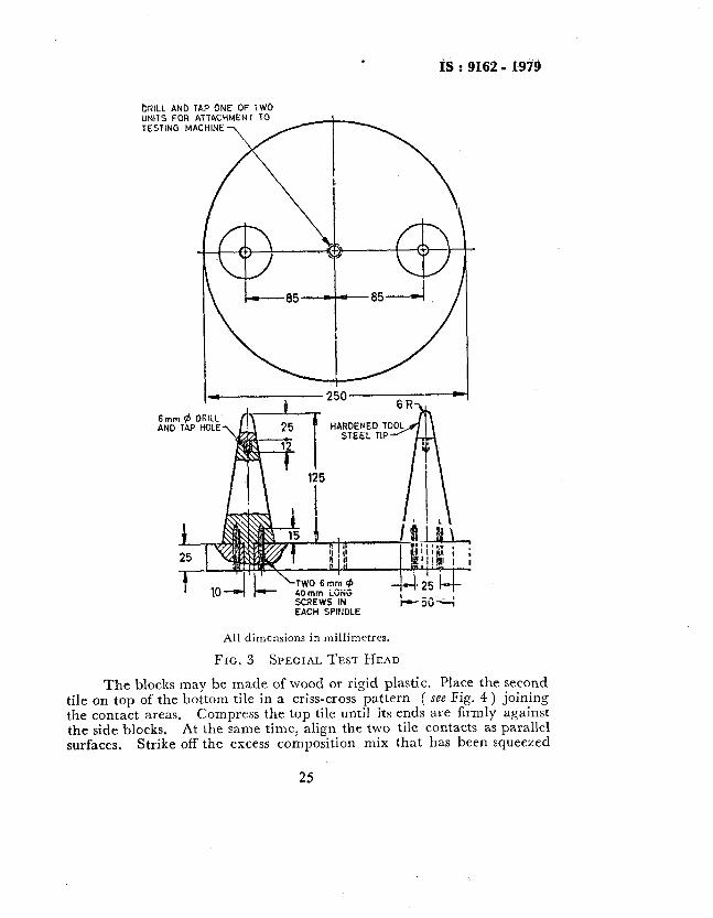
11.2.6 Special Test Head - consisting of two units of the type shown in Fig. 3.
11.2.7 Oven -thermostatically controlled with interior of non-corroding material to maintain a temperature of 105 & 5°C.
-11.2.8 Tile - ceramic unglazed vitreous acid resisting tile conforming to IS : 4457-1967*.
11.3 Conditioning the Tile - The tiles shall be cut to rectangular shape of dimension 198.5 x 100 x 35 mm. Dry the tiles at 105 f 5°C for 24 hours in the oven and allow to cool to 27 _& 2°C. The crossed tiles shallbe at right angles to one another and centered one on the other when the specimen is assembled. At the same time, mark the contact points for the load test in the special test head.
11.4 Preparation of Mortar - Prepare epoxy resin composition in the manner recommended by the manufacturer.
11.5 Preparation of Grossed Tile Test Specimen - Apply the com- position over the area on the tile that is marked for the joint. The contact area of each tile shall be throughly applied with the composition and the amount applied shall be 25 to 50 percent in excess of the required amount to ensure a full joint. Place one of the tiles, with the side on which com- position has been applied facing up, on a flat level surface. Then place two blocks on each side of the joint area of the bottom tile. The height of the blocks shall be uniform and is dependent on the thickness of the mortar joint desired ( see Note ).
*Specification for ceramic unglazed vitreous acid-resisting tiles,
I 24
ifi : 9162 - 1919
bRiLL ANb UNITS FOR TESTiNG M
6mm fJ AND TP
L 25 -
4iimm LObiG SCREWS IN EACH SPINDLE
All dimensions in millimetres.
FIG. 3 SPECIAL TEST HEAD
The blocks may be made of wood or rigid plastic. Place the second tile on top of the bottom tile in a criss-cross pattern ( see Fig. 4 ) joining the contact areas. Compress the top tile until its ends are firmly against the side blocks. At the same time, align the two tile contacts as parallel surfaces. Strike off the excess composition mix that has been squeezed

. IS : 9162 - 1979
from all sides of the joint. the joint area.
Remove the blocks, taking care not to disturb Allow the composition to set for a minimum of 24 hours
before handling the specimens. NOTE - For example if a 5 mm thick joint is desired and the thickness of the
tile is 35 mm, then the blocks should he 40 mm in height in order to provide the desired joint thickness.
FIG. 4 CROSSED - TILE SPECIMEN MOUNTED ON SPECIAL HEAD
11.5.1 Extreme care shall be taken in handling the specimens. Lifting the unit by the top tile or stacking specimens one above the other shall be avoided.
11.6 Conditioning of the Test Specimens - Condition the specimens for 2 weeks at 27 f 2°C.
11.7 Procedure - Mount the test specimen in the special test head as shown in Fig. 3. Place the specimen on the support points of the bottom head in such a manner that the specimen is balanced. The marked contact points on the bottom surface of the top tile shall match the support points of the bottom test head. Position the apparatus to match the contact points of the top head with the marked contact points on the top surface of the bottom tile.
11.7.1 Apply the load by setting the free cross head movement at the rate of 5 mm per minute.
11.7.2 Inspect the joint after testing and note whether the failure was in the composition or between the composition and the tile, and the relative areas involved. This will indicate which is the greater, cohesion within the composition or adhesion between the composition and tile.
11.8 Calculation - Calculate the bond strength as follows:
26

IS : 9162 - 1979
where
B-
w-
A=
bond strefigth in N/mms,
load at failure in N, and area of joint in mms.
11.9 -Report - The report shall include the following: a) Details of composition tested, b) Identification of tile used, c) Age of specimen at the time of test, d) Number of specimens tested, e) Type of failure by cohesion or adhesion, and f) Average bond strength.
12. LINEAR SHRINKAGE AND COEFFICIENT OF THERMAL EXPANSION
12.1 Object -This method is intended to measure the coefficient of thermal expansion of epoxy resin composition for floor topping over normal temperature ranges.
12.2 Apparatus
12.2.1 Scales - The scales used in weighing materials shall conform to the following requirements:
a) On scales in use the permissible variation at a load of 2 000 g shall be -& 2.0 g; and
b) The permissible variation on new scales shall be half of this value. The sensibility reciprocal shall be not greater than twice the permissible variation.
12.2.2 Weights -The permissible variations on weights in use in weighing materials shall be as prescribed in Table 2. The permissible variations on new weights shall be one-half of the values given in Table 2.
12.2.3 Equipment for Mixing - This may consist of a container of suitable size preferably made of corrosion-resistant metal, or a porcelain pan and a sturdy spatula or trowel.
12.2.4 Specimen Moulds - Permitting the moulding of bars~with a metal stud embedded in each end. The bars shall be 6.45 >( 6.45 cm and 25.4 cm long between studs when moulded. A standard 25.4 cm metal bar shall be provided; this is used to space the studs.
12.2.5 Studs - nickel alloy studs, knurled on one end and threaded on the other ( for securing in end blocks ), approximately 2 cm long.
27
IS : 9162 - 1979
12.2.6 Comljarator - a direct reading dial micrometer to permit readings to O*OOO 25 cm.
12.2.7 Micrometers - One having a range suitable for measuring the studs and one having a range suitable for measuring the standard 25.4 cm bar, both readable to O*OOO 25 cm.
12.2.8 Constant Temperature Oven - an oven capable of attaining temp- eratures to 205°C. The oven should be capable of maintaining a set temperature constant to f 1°C.
12.3 Ferjt Specimens
12.3.1 Temperature - The standard temperature of the constituents, mould apparatus, and the temperature in the vicinity of the mixing operation shall be 27 & 2”C, unless otherwise specified by the manu- facturer. The actual temperature shall be recorded.
12.3.2 .Number of Specimens - A minimum of four test bar specimens shall be prepared.
12.3.3 Preparation of Mix - The mix shall be prepared as follows:
a) The mix proportions shall be specified by the manufacturer. If the proportions so specified are by volume, the constituents shall be weighed and the corresponding proportions by mass shall be reported.
b) A standard batch size of 2 400 g shall be mixed, from which four bars of 6.45 x 6.45 x 25.4 cm ( approximate ) shall be prepared.
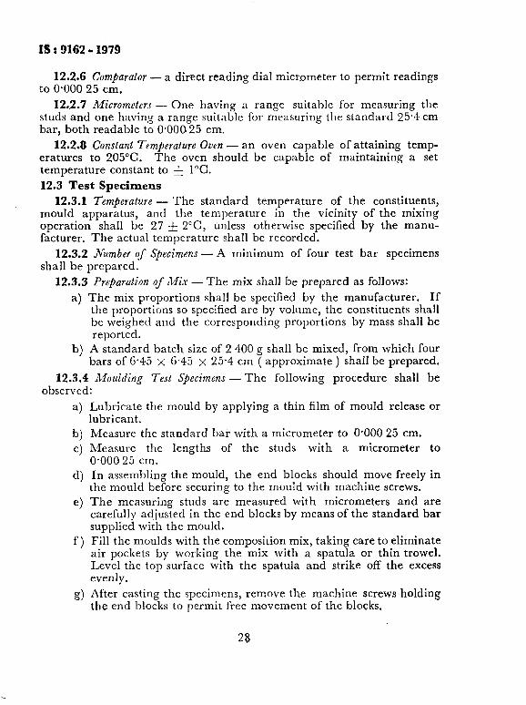
12.3.4 Moulding Test Specimens -The following procedure shall be observed:
a)
b) Cl
4
e>
f 1
9)
Lubricate the mould by applying a thin film of mould release or lubricant. Measure the standard bar with a micrometer to OS000 25 cm. Measure the lengths of the studs with a micrometer to O-000 25 cm. In assembling the mould, the end blocks should move freely in the mould before securing to the mould with machine screws. The measuring studs are measured with micrometers and are carefully adjusted in the end blocks by means of the standard bar supplied with the mould. Fill the moulds with the composition mix, taking care to eliminate air pockets by working the mix with a spatula or thin trowel. Level the top surface with the spatula and strike off the excess evenly.
After casting the specimens, remove the machine screws holding the end blocks to permit free movement of the blocks,
28
1.5 : 9162 - 1979
12.4 Conditioning Test Specimens
12.4.1 Keep the specimens in their respective moulds for a period of 24 hours after moulding. Then disassemble the moulds, remove the bars, and remove the blocks~from the measuring studs.
12.5 Procedure
12.5.1 For Linear Shrinkage
12.5.1.1 Determine the length of the bar by inserting it in the length comparator,
NOTE - In cases where shrinkage in the specimens is great enough that comparator readings are no longer possible, insertion of a spacer ( such as a metal washer ) under the bottom stud holder of the comparator will enable readings to be made. When this is necessary, standard bar readings will also change and proper adjustments in calculation should be made.
12.5.1.2 The frequency of shrinkage measurement depends on the information desired; for example, if it is desired to follow the shrinkage at room temperature, or at a specific temperature, readings can be made easily as long as shrinkage continues. Heat the specimens to obtain a constant length. A typical schedule is daily for 2 weeks at 22°C then after 72 hours at 100°C. If the specimens are heated to induce cure, cool overnight at 22°C before measuring.
12.5.2 For Corficient of Thermal Exjansion
12.5.2.1 Use the specimens previously used for shrinkage determina- tions. Heat the specimens in an oven at 105 f 5°C to constant length, and condition at 27 & 2°C for a minimum of 16 hours.
12.5.2.2 Determine the length of each bar at 27 f 2°C by measuring with the length comparator. Then place the bars in an oven heated to 100°C.
12.5.2.3 The following day, remove the bars quickly one at a time and measure. Remove the bars at a rate that does not permit the temperature of the oven to drop below the established elevated temperature. If the specimen does not return to its original length on cooling to 27 f 2”C, shrinkage is still taking place and the procedure mentioned in 12.5.2.1 and 12.5.2.2 shall be repeated.
_NOTE - Usually, the length can be read within four to five seconds after removal from the oven.
12.6 Calculations
12.6.1 Linear Shrit;kuge - Calculate the shrinkage and the standard deviation for the four specimens as follows:
Percent linear shrinkage = [ (L, - L)/L,] x 100
29

IS : 9162 - 1979
where
L, = original length ( length of standard bar ), cm; and
L = length as measured during or after cure, cm.
12.6.2 Coeficient of Linear Thermal ExPansion - Calculate the coefhcient of linear thermal expansion of the four specimens as follows:
5-r-w e = I(W-X)
where
e = coefficient of linear thermal expansion, mm/mm%;
5 = length of bar, including studs, at elevated temperature, mm;
r = length of stud expansion, mm = Y x T x X ( where K is the linear coefficient of thermal expansion per “C of the studs ) ;
W = length of bar, including studs, at lower temperature, mm;
T = temperature change, “C; and
X = length of the two studs at lower temperature, mm.
12.7 Report - The report shall include the following:
a) Manufacturer’s name and details of the mix;
b) Mixing ratio;
c) Conditioning procedure;
d) Test conditions ( temperature and humidity );
e) Age of test specimens in days, including heat cycles; and
f) Individual and average results of shrinkage and coefficient of thermal expansion.
13. WATER ABSORPTION
13.1 Object - To determine the absorption of epoxy resin compositions of floor topping.
13.2 Apparatus
13.2.1 Balance - of capacity of 100 g with a sensitivity of 0.5 mg.
13.2.2 Sflecijc Gravity Balance - for determining the specific gravity of both liquids and solids with a sensitivity of O-5 mg.
13.2.3 Flask - a glass flask carrying a reflux condenser and provided with interchangeable glass joints.
30
IS : 9162 - 1979
13.2.4 Moulds -plastic tube of 25 mm diameter and 25 mm height having sufficient wall thickness tobe rigid and retain dimensional stability during the moulding operation. A 6 mm thick flat plastic sheet shall be provided on which one open end of the mould may rest.
13.2.5 Oven -capable of maintaining a temperature of 105 f 5°C.
13.3 Preparation of the Mix - Prepare the mix in appropriate propor- tion specified by the manufacturer in a suitable flat bottom container made of non-corrodible metal or a porcelain enamelled pan using a trowel. Place the liquid in the mixing container, and approximately three- fourths of~the dry composition and mix with the liquid by working with a trowel, turning the mass from bottom to top occasionally. When the mass is uniform add the remainder of the dry composition and continue the mixing in the same manner until the composition is uniformly mixed. Record the time required for mixing.
13.4 Preparation of Test Specimen- Fill the mould with the mix prepared as described in 13.3. As the moulds are being filled, work a thin narrow blade vertically through the mix to ~permit the escape of the air which would cause void spaces. and strike off the excess evenly.
Level the top surface with the spatula
13.5 Conditioning of the Test Specimens - Keep the specimens in the respective moulds for a period of 24 hours. Demould and place the specimens in an oven controlled at 105 to 110°C until they reach constant mass D. Consider the specimens as having reached constant mass when they do not lose more than 0.1 percent of their original mass in 24 hours at 105 to 110°C. Cool the specimens to 27 f 2°C in desiccator before weighing.
13.6 Number of Specimens - Six specimens shall be prepared.
13.7 Procedure - Place the weighed specimens in the flask. The flask shall have wire screen or glass beads at its bottom to prevent the specimen from coming in direct contact with the heated bottom of the flask. Add water until the specimens are completely covered. Install the water cooled condenser and heat the flask by means of a hot plate or heating mantle. Boil for 2 hours. After boiling, cool the flask to 27 + 2°C. The cooling may be accelerated by running cold water over the outer surface of the flask while swirling the flask,
13.7.1 Determine the suspended mass S of each test specimen while suspended in the liquid, to the nearest mg. If the mass of the suspension pan immersed in the liquid cannot be counter-balanced, subtract the tare mass with the suspension pan immersed in the liquid two the same depth as when the specimen is in place to obtain the net suspended mass s.
31
IS : 9162 - 1979
13.7.2 After determining the suspended-mass, blot each specimen with a smooth cotton cloth to remove all liquid droplets from the surface and determine the saturated mass W. Excessive blotting shall be avoided as it will introduce error by withdrawing liquid from the pcres of the specimen.
13.8 Calculate the absorption in percent as follows:
A- w-D - D
x 100
where
A = absorption in percent,
W = saturated mass of specimens in g, and
D = mass of specimen after conditioning to constant mass in g.
13.9 Report - Report the average value of the six specimens.
13.10 Retest - If a single value deviates from the average value by more than 15 percent, this result shall be discarded and the average of the remaininq specimens whose deviation does not exceed this limit shall be taken. Defective specimens shall be discarded. If after discarding the defective specimens and those whoye value varies more than 15 percent from the average value, there remain less than four specimens, the test shall be repeated.
14. CHEMICAL RESISTANCE
14.1 Object - To evaluate the chemical resistance of epoxy resin com- position for floor topping under anticipated service conditions. ( This method is intended for use as a relatively rapid test in evaluating the chemical resistance. )
14.1J The method provides for the determination of changes in the following properties of the test specimens and test reagents after exposure of the specimens to the reagent:
a) Mass of specimens,
b) Appearance of specimens,
c) Appearance of immersion mediums, and
d) Compressive strength of specimens.
14.2 Significance - The results obtained by this method should serve as a guide but not as the sole basis for selection of cornposition mix for a particular application. No attempt has been made to incorporate into the method, all the various factors which may enter into the serviceability of a mortar when subjected to chemical solutions or solvents.
32

IS:9162 -1979
14.3 Apparatus
14.3.1 Balarzcc - of capacity 1 kg, sensitive to 0.1 g.
14.3.2 Equipment for Mixing - This may be a container of suitable size made of corrosion resistant metal or a porcelain pan and a spatula or trowel.
14.3.3 Specimen Moulds - See 13.2.4.
14.3.4 Containers
a) Wide mouth glass jars - of sufficient capacity, fitted with plastic or plastic lined metal screw caps for low temperature tests involving solutions or solvents of low volatility,
b) Erlenmeyrjosk~ - of sufficient capacity each fitted with standard taper joints and reflux condenser attachment for use with volatile solutions or solvents.
c) Containers as described in 14.3.4(a) and (b) having an inert coating on their inner surfaces or containers of a suitable inert material ( such as polyethylene ) for use with solutions which attack glass.
14.3.5 Constant Temperature Oven or Liquid Bath - capable of maintain- ing temperature within a range of & 2°C.
14.3.6 Compression Testing Machine - universal type. .
14.4 Reagents -- The test reagents shall consist of reagents, solutions or products to which the topping is to be exposed in service.
14.5 Test Specimens
14.5.1 The test specimens shall be cast right cylinders 25 & 1 mm in diameter and 25 f 1 mm in height with flat smooth faces normal to the axis of the cylinder prepared in moulds without using any release agents.
14.5.2 The number of specimens required is dependent upon the number of test solutions to be employed, the number of different tempera- tures at which testing is performed and the frequency of test intervals. The test specimens shall consist of sets of at least three cylinders for one solution at a single temperature and for each test interval. In addition, one set of at least three specimens shall be available for test immediately following the conditioning period, and other sets of at least three, equivalent to the number of test temperature, for test after ageing in air at the test temperature for the total test period. The total number of specimens required shall be calculated as follows:
A’-=3(SxIxG)+3,7-f3
where
fl = number of specimens,
33
ISr9162-1979
S = number of solutions,
T = number of test temperatures, and
G = number of test intervals.
14.6 Preparation of Specimens - They shall be prepared as described in 14.6.1. If the faces of a specimen are not flat, smooth and normal to the cylinder axis, they may be sanded, ground or machined. Care shall be taken that the frictional heat developed during such operations does not damage the specimen.
14.6.1 Mix in the proper proportion and in the manner specified by the manufacturer. Place the mix in the mould with a spatula taking care to ensure complete filling of the mould cavity without entrapment of the air. Scrap off excess mix even with the face of the mould making the exposed surface as smooth and even as possible. Permit the mix to remain in the mould at least for 24 hours to allow removal without danger of deformation or breakage.
14.7 Conditioning of Test Specimens - Age the specimen for a period of 7 days in air at 27 -+. 2°C.
14.8 Test Conditions - Test conditions, such as immersion medium, temperature, etc, shall simulate the anticipated service conditions as closely as possible.
14.9 Procedure
14.9.1 Measurement of Specimen Diameters - Immediately following the conditioning period, the diameter of all test specimens shall be measured to the nearest 0.01 mm using a micrometer. Two measurements at right angles to each other shall be taken and the average of the two values shall be reported.
14.9.2 Exposwe Weighing and Visual Inspection of Test Specimens - Follow-
ing the conditioning period, weigh all the specimens to the nearest O*OOO 1 g on an analytical balance and record the values. Prior to immersion, record a brief description of the colour and surface appearance of the specimens and the colour and clarity of the test solution. Place the weighed specimens to be immersed in suitable containers resting on their curved sides, care being taken to prevent the cylinder faces from coming in contact with each other. The total number of specimens per container is not limited except by the ability of the container to hold the specimens, plus the requisite amount of test solution per specimen. However, the specimens shall always be an even number. Add approximately 150 ml of the test solution for each specimen, and place the closed container in a constant temperature oven adjusted to the required temperature or in a
34

IS: 9162 - 1979
suitably adjusted liquid bath. Examine the specimens after 1, 7, 14, 28, 48 and 56 days of immersion to determine the nature of attack.
14i9.2.1 The specimen shall be cleaned by three quick rinses in running cold tap water and dried by blotting with a paper towel between each immersion. After the final blotting, the specimen shall be allowed to dry for half an hour resting on its curved surface. The specimen shall be weighed to the nearest milligram, and the compression test shall be conducted.
NOTE-If the specimens are to be forwarded to a testing laboratory for conducting the compression test, they may either be transported in the corroding environment. or each cleaned and dried sample placed in an individual airtight bag and so held until ready for weighing and testing. The elapsed time between the removal of the specimens from the corroding environment and the compressive tests should be uniform for all specimens.
14.9.2.2 Note any indication of surface attack on the specimen, any discolouration of the test solution, and the formation of any sediment.
14.9.3 Compressitle Strength Determination of Test Specimen - Determine the compressive strength for one set of two specimens immediately follow- ing the conditioning period; for one set of two specimens after each inspection period for each solution and each test temperature, and for one set of two specimens after ageing in air for the total test period at each test temperature. Break the specimens following the weighing operation and record~the maximum load. Place the specimens in the testing machine so that the plane faces of the cylinder are in contact with the surface of the compression tool or cage. Apply the load to the specimen at the rate of 4 N/mm2 per minute.
14.9.4 Changing of Immersion Medium -Discard and replace the test solution with fresh material after each period. Solutions which are known to be unstable such as aqueous sodium hypochlorite shall be replaced as often as necessary in order to maintain original chemical composition and concentration.
14.10 Calculations
14.10.1 Mass Change - Calculate to the nearest 0.01 percent the percentage loss or gain in mass of the specimen during immersion for each examination period.
Mass change, percent = (C-IV) X 100 c
where
C = conditioned mass of specimen in g, and
LV = mass of specimen after immersion in g.
35

NOTE-A result showing plus sign shall indicate a gain in mass and minus sign shall indicate a loss.
14.10.1.1 Construct a graph employing the average percentage Of mass change of all specimens at a given examination period after immersion in a particular test solution at a given temperature, plotting the percentage of ‘mass change as the ordinate and the test period, in days as the abscissa.
14.10.1.2 The absolute compressive strength in N/mm2 should be shown for the initial specimen and the final specimen. These values should be noted parenthetically near the plot point of each value.
14.X0.2 Change in Compressive Strength -Calculate to the nearest 0.01 percent, the percentage decrease or increase in compressive strength of the specimen during immersion for each examination period. The cross- sectional area of the specimen shall be based on the diameter as determined by the method given in 14.3.1.
Change in compressive strength, percent = ( Sl - Sz ) .- -S---.-.-- x lO0 1
where
S1 = maximum load per cross-sectional area of specimen after conditioning period, in N/mm?; and
S, = maximum load per cross-sectional area of specimen after test period, in N/mms.
NOTE - A result showing a plus sign will indicate a gain in compressive strength and a minus sign will indicate a loss.
14.10.2.1 Construct a graph employing the average percentage of change in compressive strength of the two specimens broken at a given examination period after immersion in a particular test solution at a given temperature, -plotting the percentage of change in compressive strength as the ordinate and the test period, in days as abscissa,
14.11 Interpretation of Test Results
14.1X.1 Mass Change - Because of the chemical nature of different types of mortars, the rate of mass change with time is of more significance than the actual value at any one time. A plot of the test results will indicate whether a particular mortar will approach constant mass in time or will continue to change in mass as the test progresses.
14.11.2 Apprunce of Specimen -Visual inspection of the exposed specimen for surface cracks, loss of gloss, etching, pitting, softening, etc, is very important in cases where initial mass changes are high.
36

IS : 9162 - 1979
14.11.3 Appearance of Immersion Medium - Discolouration of the test solution and the formation of sediment are significant factors. An initial discolouration coupled with a high mass loss may indicate extraction of soluble components. Continuation of the test with fresh solution will indicate whether or not the attack is progressive.
14.11.4 Change in Compressive Strength -The same considerations hold true as given in 14.11.1 and, therefore, the rate of change in compressive strength is an important characteristic to be determined.
14.12 Report - The report shall include the following:
4 b) Cl d) e) f >
!a
h)
Manufacturer’s name and the details of the mix;
Mixing ratio;
Conditioning procedure;
Test conditions, such as immersion medium and temperature;
Colour and surface appearance of specimen before testing;
Total duration of test in days, and examination periods in days for each examination period the data given in 14.12.1 are required; Graph showing percent mass change plotted against test period; and Graph showing percent change in compressive strength plotted against test period.
14.12.1 The following information shall be required:
a) Average percentage of mass change of specimens;
b) Appearance of specimens after immersion ( surface cracks, loss of gloss, etching, pitting, softening, etc );
c) Appearance of immersion medium ( discolouration, sediment, etc ); and
d) Average percent change in compressive strength of specimens.
15. ABRASION RESISTANCE
15.1 Object - To determine the abrasion resistant property of epoxy resin compositions for floor toppings.
15.2 Preparation of Test Specimens - A minimum of six specimens shall be prepared for the test. The test specimens shall be square in shape and of size 7.06 x 7.06 cm ( that is 50 cm2 in area ). These shall be sawn
37
IS< 9162 0 1979
off from plain cement concrete tile (see IS : 1237-1959* ). The deviation in the length of the specimen shall be within f 2 percent. One surface of the specimen shall be coated with epoxy resin compositions, of required thickness as given in 5.1 of IS : 4631-19687 and allowed to cure according to the directions of the manufacturers,
15.3 Apparatus and Accessories
15.3.1 Abrasion Testing Machine - The abrasion of specimens shall be carried out in a machine conforming essentially to the requirements described in Appendix A. The abrasive powder used for the test shall conform to the specification given in Appendix B.
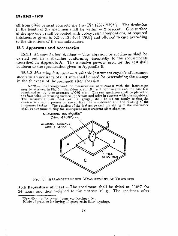
153.2 Measuring Instrument - A suitable instrument capable of measure- ments to an accuracy of 0.01 mm shall be used for determining the change in the thickness of the specimen after abrasion.
NOTE-The arrangement for measurement of thickness with the itstrument may be as given in Fig. 5. Shoulders A and B are at right angles and the base c is machined at top to an accuracy of 0.01 mm. The test specimen shall be placed on the base with its wearing surface uppermost and sides in contact with the shoulders. The measuring instrument (or dial gauge) shall be set up firmly SO that the contractor slightly presses on the surface of the specimen and the reading of the instrument taken. The position of the dial gauge and the sitting of the contractor shall be the same during the subsequent measurement after abrasion.
MZASURING INSTRUMENT
(DIAL GAUGE) 7
WEARING SURFACE UPPER MOST
FIG. 5 ARRANGEMENT FOR MEASUREMENT OF THICKNESS
15.4 Procedure of Test -- The specimens shall be dried at 110°C for 24 hours and then weighed to the nearest 0.1 g. The specimen after
*Specification for cement concrete flooring tiles. tCode of practice for laying of epoxy resin floor toppings.
38
18 : 9162 - 1939
initial drying and weighing shall be placed in the thickness measuring apparatus ( see Note under 15.3.2 ) with its wearing surface uppermost, and the reading of the measuring instrument taken.
15.4.1 The grinding path of the disc of the abrasion testing machine ( see Appendix A ) shall be evenly strewn with 20 g of the abrasive powder. The specimen shall then be fixed in the holding device with the surface to be ground facing the disc, and loaded at the centre with 300 N. The grinding disc shall then be put in motion at a speed of 30 revlmin. After every 22 revolutions, the disc shall be stopped, the abraded tile powder and the remainder of the abrasive powder shall be removed from the disc, and fresh abrasive powder in quantities of 20 g applied each time. After 110 revolutions, the specimen shall be turned about the vertical axis through an angle of 90’ and then the test continued under the same conditions until 220 revolutions have been completed altogether. The disc, the abrasive powder and the specimen shall be kept dry throughout the duration of the test. After the abrasion is over, the specimen shall be reweighed to the nearest 0.1 g. It shall then be placed in the thickness
‘measuring apparatus once again in an identical manner and the reading taken with the same position and setting of the dial gauge as for the measurement before abrasion.
15.5 Deters&nation of Wear - The wear shall be determined from the difference in readings obtained by the measuring instrument before and after the abrasion of the specimen. The value shall be checlied up with the average loss in thickness of the specimen obtained by the following formula: -
t = 10 ( w1- w2 1 Vl WI x A
where
t= average loss in thickness, in mm;
w1= initial mass, in g, of the specimen;
W‘A = final mass, in g, of the abraded specimen;
Vl = initial volume, in ems of the specimen; and
A= surface area, in cmz, of the specimen.
16. TH%RMAL CONDUCTIVITY
16.1 Object
16.1.1 This method covers the determination of the existing thermal conductivity by means of guarded hot plate of dry specimens of epoxy resin composition within the limits specified in 16.1.2 and the coelhcients
39

1s 8 9ifS - is49
obtained apply strictly only to the particular samples as tested~and for the specified thermal and environmental conditicns of each test.
16.1.2 For practical purposes, this method shall be limited to determina- tions on specimens having thermal conductances not in excess of 60 Wlrn2.k and thickness conforming 16.6.1.
16.1.3 Two different types of guarded hot plate apparatus arc described. They are similar in principle but differ enough in construction to warrant separate descriptions for each in regard to design. The low-temperature guarded hot plate, which has metal surface plates and a definite guard gap ( see 16.4.3 ), is generally used for measurements at mean temperatures such that the temperature of the cold surface may be as low as 77 K or that of the hot surface as high as 550 K. It is described in 16.4. The high-temperature guarded hot plate, which may or may not have metal surface plates and may or may not have a definite guard gap, is ordinarily used for measurements where the hot plate temperature is greater than 550 K and less than 1 350 K. It is made of a cast, or otherwise formed, electrically insulating ( at the highest temperature of operation ) refractory material. Metal surface plates may or may not be used although they are recommended to ensure a more uniform temperature distribution on the surfaces of the plate. The high-temperature design is described in 16.5. If compliance with this method is to be reported, then all measurements made with specimen hot surface temperatures below 550 K shall be carried out using a g:larded hot plate having metal surface plates and a definite guard gap. In all other respects, the method is the same for both types of apparatus. It is intended, in presenting these descriptions, to indicate the essential elements and details which experience has shown to be necessary or important for reliable measurements by this method.
16.1.4 For satisfactory results in conformity with this method, the principles governing the size, construction, and use of the apparatus described in this method should be followed. If the results are to be reported as having been obtained by this method, then all partinent requirements prescribed in this method shall be met,
16.2 Significance -The thermal conductivity of a material (a) may vary due to variability of the material or samples of it, (b) may be affected by moisture or other conditions, and (c) may change with time or high temperatures. It should be recognized therefore tha.t the selection of a typical value of thermal conductivity representative for a material, or for particular applications, if it is practically feasible, should be based on a consideration of these factors and an adequate amount of test information.
40
18 : 9162 - 1979
16.3 Terminology
16.3.0 For the purpose of this method the following symbols and definitions shall apply.
16.3.1 Symbols
h = thermal conductivity, W/m.k C = thermal conductance, W/ms.k R = thermal resistance, Kms/W
4 = time rate of heat flow, W A = area measured on a selected isothermal surface, rn2. L = thickness of specimen measured along a path normal to
isothermal surfaces, m tl = temperature of hot surface, K t2 = temperature of cold surface, K
16.3.2 Thermal Conductivity, h of a Homogeneous Material is the time rate of heat flow, under steady-state conditions, through unit area, per unit temperature gradient in the direction perpendicular to an isothermal surface ( see Note ). For a flat slab, it is calculated as follows: I
x = qL/A (tl- te>
NOTE - Materials are considered homogeneous for the purpose of this method when the value of the thermal conductivity is not affected by a change in thickness, L, or in area, A, within the range normally used.
16.3.3 Thermal Conductance C, of a Body Between Two Dejinite Surfaces is the time rate of heat flow between these surfaces, under steady-state conditions, divided by the difference of their average temperatures and by the area~of one of the surfaces. The average temperature is one which adequately approximates that obtained by integrating the tempera- ture of the entire surface. The thermal conductance of a flat slab is calculated as follows:
c = q/A ( t1 - t2 ) = X/L
16.3.4 Thermal Resistance, R is the reciprocal of thermal conductance. For a flat slab, it is calculated as follows ( see Note ):
R = 1/C= L/h
NOTE - The planeness of the surface can be checked with a steel straightedge held against the surface and viewed at grazing incidence with a light behind the straightedge. Departures as small as 0.025 mm are readily visible, and larger departures can be measured using shim-stock or thin paper.
41
IS : 9162 - 1979
16.4 Metal-Surfaced Hot Plate
16.4.1 The general features of the metal-surfaced guarded hot plate are shown schematically in Fig. 6. The plates are usually square, but round plates are sometimes used. The term ‘ guarded hot plate’ is applied to the entire assembled apparatus, including the heating unit, the cooling units, and the edge insulation. The heating unit consists of a central or metering section and a guard section. The central section consists of a central heater and central surface plates. The guard section consists of one or more guard heaters and the guard surface plates. The surface plates are usually made of noncorroding metal of high thermal conductivity. The working surfaces of the heating unit and cooling plates should be smoothly finished to conform to a true plane as closely as possible, and should be checked periodically. The maximum departure of the surface from a plane shall not exceed 0.25 mm/m.
16.4.2 In the design of the guarded hot plate, the following points should be considered:
a) Material used in its construction with respect to their performance at the temperatures at which the plate will be operated, and
b) The electrical design of the heater and the design of the cooling plate to assure adequate capacity and suitable characteristics for the intended use.
In all cases, the guarded hot plate shall be so designed and constructed that in operation the two faces of the central section, and of the guard section, shall be substantially at the same uniform temperature, and that the heating units do not warp or depart from planeness at the operating temperatures.
16.4.3 Heating units shall have a definite separation orgap not greater than 3 mm between the central surface plates and guard surface plates ( see Note ). The separation between the heating windings of the central section and the contiguous guard section shall not exceed 20 mm, and this separation is allowable only if the spacing bars on either sides of the separation are of a high conductivity material such as copper, in order to distribute heat to the surface plates. In all other cases, the heater winding separation shall not exceed 3 mm. The dimensions of the test area shall be established by measurements to the centres of the separations that surround this area. The surfaces of all plates shall be painted or otherwise treated to have a total hemispherical emittance greater than 0.8 at operating temperatures.
NOTE - It is recommended that the area of the gap in the plane of the surface plate be not more than 6 percent of the metering section area on that side.
42
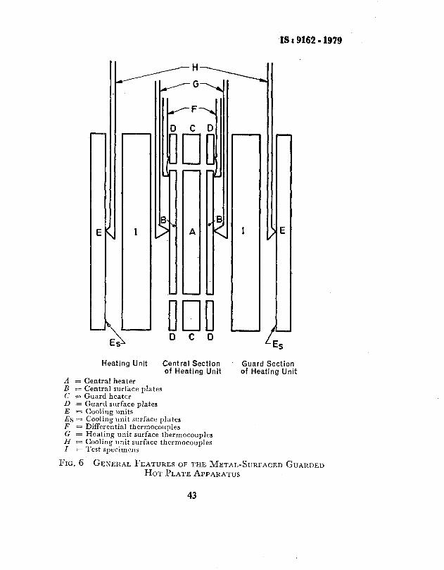
L
Heating Unit Central Section of Heating Unit
Guard Section of Heating Unit
A j= Central heater B = Central surface plates C = Guard heater D = Guard surface plates E = Cooling units Es = Cooling unit surface plates F = Differential thermocouples G = Heating unit surface thermocouples H = Cooling unit surface thermocouples Z = Test specimens
FIG. 6 GENERAL FEATURES 01; THE METAL-SURFACED GUARDED HOT PLATE APPARATUS
43

m9162-i979
16.4.4 The guarded hot plate shall be provided with a suitable means of detecting temperature imbalance between the area of the central and guard surface plates contiguous to the separation between them. The temperature-sensing elements shall be distributed to register adequately the temperature balance existing along the length of the central section periphery. The temperature-sensing elements may be read either indivi- dually to indicate any temperature difference that may exist, or they may be connected to be read differentially to indicate such temperature difference directly. Thermocouples are generally used for this purpose, with connections arranged so that they are read as a differentially connected thermopile. The detection system shall be sufficiently sensitive to assure that variation in conductivity due to gap temperature imbalance shall be restricted to not more than O-5 percent. For testing at the lower temperatures, particular caution shall be used in designing for adequate sensitivity of the thermopile measurement and control system.
16.4.5 The cooling units shall have surface dimensions at least as large as those of the heating unit including the guard heater. They shall consist of metal plates maintained at a uniform temperature lower than that of the heating unit, either by a constant-temperature fluid, or by electrical heating, or by thermal insulation of uniform conductance applied on the outertnost surfaces, as appropriate for the cooling unit temperature desired.
16.4.6 For measuring the surface temperature of the central section of the heating unit, each of the central surface plates shall be provided, with permanently installed thermocouples set in grooves or just under the working surface. The number of such thermocouples on each side shall be not less than 5 J 2, where A is the area in m2 of one side of the central surface plate. There shall be the same number of thermocouples permanently and similarly installed at corresponding positions in the facing cold plate. If the hot and cold plate thermocouples on each side are to be connected differentially, which is usual, they shall be electrically insulated from the plates.
16.4.7 Means for imposing a reproducible constant pressure of the plates against the specimens to promote good thermal contact ( see Note 1 ) and for measuring the effective thickness of the specimen to within 0.5 percent (see Note 2 ) shall be provided.
NOTE 1 - A steady force thrusting the cold plates toward each other can be imposed by means of a calibrated compressed spring, or a system of levers and dead weights, or an equivalent method. It is unlikely that a pressure greater than 2.5 kPa on the specimens would be required; for easily-compressible specimens, small stops interposed between the corners or edges of the’cold plates, or sbme othe; positive means, may be used to limit the compression of the specimens, and a constant-pressure arrangement is not needed.
44
IS : 9162 - 1979
NOTE 2 - Because of the changes of specimen thickness possible as a result of temperature, or compression by the plates, it is recommended that specimen thick- ness be measured in the apparatus, at the existing test temperature and compression conditions, when possible. Gauging points, or measuring studs at the outer four corners of the cold plates or along the axis perpendicular to the plates at their centres, will serve for these measurements. The effective combined specimen thick- ness is determined by the difference in the micrometered distance, or average distance, between the gauging points when the specimen is in place in the apparatus, and is not in place, and the same force is used to press the cold plates towards each other.
16.4.8 The best method of determining the temperature drop in the specimen depends upon its characteristics, and in some instances the choice of method is left to the judgement of the operator. For non-rigid specimens with flat uniform surfaces that conform well to the flat working surfaces of the plates, the temperature drop in specimens of thermal conductance less than 10 W/ma. K shall be taken as that indicated by the thermocouples permanently set in the hot and cold surface plate, and the thickness of the specimen shall be taken as the mean distance between the working surface of the hot and cold plates. For non-rigid specimens of conductance greater than 10 W/ms.K, the operator’s judgement should rule in accordance with the circumstances. Rigid specimens to be tested shall have surfaces, both flat and parallel to within O-25 mm/m ( see Note I ). One method of testing rigid specimens is to install them in the apparatus with a thin sheet of suitable homogeneous material inter- posed between the specimen and each plate surface. This thin sheet should have a high thermal conductance relative to that of the insulating material being tested. The conductance of the composite sandwich ( sheet/rigid specimen/sheet ) is determined using the temperature drop indicated by the permanent thermocouples in the hot and cold surface plates. If it is not already known, the conductance of the interposed sheets alone is similarly measured in a separate test made at the same mean temperature and with the same compressive force on the plates. The conductance of the rigid specimen is then calculated from the two conductances obtained. Another method of determining the conductance of a rigid specimen is to interpose the thin layer of material between the specimen and plates as indicated above, and to determine the temperature drop across the rigid specimen by means of separate thermocouples mounted flush with, or interior to, the surface of the rigid specimen ( see Note ~2 ). The number of separate thermocouples used on each side of the specimen shall be not less than lot/x, where A is the area in rn% of one side of the central surface plate. If separate thermocouples are used, the effective thickness of the specimen shall be taken as the average distance, perpendicular to the face of the specimen, between the centres of the thermocouples on the two sides.
45
IS : 9162 - 1979
NOTE 1 - A rigid specimen is one of a material too hard and unyielding to be appreciably altered in shape by the pressure of the hot and cold plates, for example, a slab of glass or hard plastic.
NW~JC 2 -This method of measuring the specimen temperature drop may be subject to unccrtaintics. Difficult to evaluate, among them being the effects of: (a) distortion of heat flowlines in the immediate vicinity of the thermocouple, due to its presence, (b) imprecision in ascertaining the exact position of the effective thermocouple junctions, and (c) local inhomogeneities in the surface of the specimen at the thermocouple junctions, such as pores, voids, or inclusions.
16.4.9 Thermocouples mounted in the surfaces of the plates shall be made of wire not larger than 0.57 mm in diameter, specimen surface thermocouples shall be made of wire not larger than 0.29 mm in diameter. The thermocouples which are used to measure the temperatures of the hot and cold faces of the specimen shall be fabricated from calibrated thermocouple wire. Thermocouples used to measure tempera- tures in the range from 77 to 170 K shall have a standard limit of error of & 1 percent.
16.4.10 A voltage-measuring system having a sensitivity of f 1 PV or better and an accuracy of f 0.1 percent or better shall be used for measurements of all thermocouple and thermopile electromotive forces.
16.4.11 Heat losses from the outer edges of the guard section and the specimens shall be restricted by edge insulation, by governing the surrounding ambient temperature, by an additional outer guard, or by a combination of these methods. Three possible configurations that could be used to restrict edge heat losses or gains are shown in Fig. 7. A useful method of determining whether or not sufficient edge guarding or insula- tion is present is to measure the average temperature, Tel at the edge of the specimen ( this can be done using a thermocouple soldered or peened to a thin metal strip centered on the edge of one of the specimens). Under these conditions:
[(ire-~m)/~~lGO’l
where Tm is the mean temperature of the specimens and d T is the temperature difference across the specimens is a satisfactory criterion. In the first two cases shown in Fig. 7, if no guard ring perimeter heater is used, the required minimum thermal resistance of the edge insulation, on the basis that the total edge heat loss shall not exceed one fifth of the heat flow through the two specimens, is given by the following equation:
R = 5”+~[(4x+2.Y) (Tm--la)/nT+rl where
x = thickness of each specimen, m;
S = length of the side ( or diameter ) of the guard section, m;
X = thermal conductivity of the specimen, W/m.K; _Y = thickness of the heating unit, m;
46

T, = T, =
mean temperature of the specimens, K; temperature of the outer surface of the edge insulation, K; and
Al-=
It should temperature difference across the specimens, K. be noted that R depends on both ( T, - T,) and AT’,
and also that since it is desirable that the net heat transfer from the outer edges of the specimens should be kept nearly equal to zero ( Tm - Ta ), should be kept small.
IS:9162-1979
HEATER -7 rGUARD
-Te
la
OUTER CYLINDRICAL
GUARD
-Te
Ta
78
Te
SECOND
GUARD HEATER
Ta
7c -
2-e = Temperature edge
2-a = Temperature ambient
FIG. 7 POSSIBLE CONFIGURATIONS TO RESTRICT EDGE HEAT Loss AND GAIN
47
IS t 9162 - 1979
16.4J2 A cabinet or enclosure surrounding the guarded hot plate, and equipped for maintaining the desired interior air temperature and dew- point, is recommended for use in tests conducted at mean temperatures differing substantially from the laboratory air temperature.
16.5 High-Temperature Guarded Hot Plate
16.5.1 The general features of the high-temperature guarded hot plate are shown schematically in Fig. ~8. The plate may have a round or square configuration, If a square plate configuration is used, it is recommended that separate independently controlled guard heaters be provided to allow for the additional heat losses which occur at the corner regions. The term ‘guarded hot plate ’ is applied to the entire assembled apparatus including the heating units, the cooling units, and the insulation. The heating units consist of (a) a central or metering section, (b) ~a guard section that shall be either a double guard heater, with the outer guard section having a width equal to or greater than one half of the inner primary guard width, or a primary guard heater with an outer cylindrical
~guard extending over the length of ~the composite sample stack, (c) additional corner heaters ( for square configuration only ), and (d) cold surface heaters. If metal surface plates are used, they should be of a suitable noncorroding metal of as high a thermal conductivity as possible. Physical separation of the central and inner guard areas is to be preferred if associated problems of alignment and flatness of the plates are minimized by suitable design. All heaters should be capable of being adjusted to any desired temperature level within the limits specified in 16.1.3. The cooling units normally consist of two liquid-cooled heat sinks with an adequate layer of insulation between them and the adjacent cold surface heater. An additional outer peripheral liquid-cooled shroud is recommen- ded ( see 16.5.11 ). The working surface of the heating units and cooling plates shall be finished smoothly to conform to a true plane as closely as possible and should be checked regularly. The maximum departure of the surface from a plane shall not exceed 0.25 mm/m (see Note under 16.3.4 ). The refractory material plates should have a thermal expansion not greater than one percent of the linear surface dimension of the hot plate. This expansion shall be computed from the difference between the length measurements taken at maximum use temperature and at room temperature.
16.5.2 In the design of the high-temperature guarded hot plate, due consideration to obtaining satisfactory performance at the temperature at which the plate will be operated shall be given. Electrical design of the heaters and the design of the cooling plates shall be such to assure adequate capacity and suitable characteristics for the intended use. The refractory plate composition should have adequate electrical resistance at
48
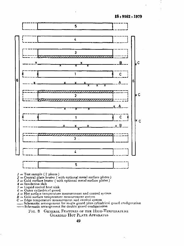
as : 9162 - 1979
!_ I 5 I i 3-w _ -k-J
X d----
X 0 X x X
-_-e-m
r-d-
J ---e-q
1 L__-_ c I ,_--_J
a__- x X X X A x x x
_--___
a---_ xA X X X ----_-
i----- ---w--3)
1 L___-
--a--- X X X 3c!2-- X
-------I -----,
__.i
t------
L____
r---
I--.__
p-- L
s---v 3
--. 5
-_-- !
C
C
C
:5 = Test sample ( 2 pieces )
Central plate heater ( with optionalmetal surface plates ) z = Cold surface heater ( with optional metal surface plates )
E Insulation slab 5 = Liquid cooled heat sink 6 = Outer cylindrical guard A E Hot surface temperature measurement and control system I3 = Cold surface temperature measurement system c E Edge temperature measurement and control system I_ Schematic arrangement for single guard plus cylindrical guard configuration ------ Schematic arrangement for double guard configuration
FIG. 8 GENERALFEATURES OF THE HIGH-TEMPERATURE GUARDED HOTPLATEAPPARATUS
49

1s : 9162 - 1979
the maximum use temperature to prevent possible power exchange between adjacent heating circuits embedded within the refractory material. The maximum permissible power exchange shall be O-5 percent of the test area power consumption at the particular test temperature. In all cases great care should be taken to ensure that there will be no com- patibility problems between the test specimens and the materials used in the construction of the plates for temperature and environment conditions of a specific measurement. In all cases, the guarded hot plate shall be so designed and constru.cted that in operation the two faces of the central section, and of the guard section, shall be substantially at the same uni- form temperature, and that the heating units do not warp or depart from planeness at the operating temperatures. The surfaces facing both sides of the test specimens should be treated so that they have a total hemispheri- cal emittance at the operating temperatures of not less than 0.7 and preferably much higher.
NOTE - At high temperatures the importance of high emittance of the surfaces adjacent to the specimens cannot be stressed too strongly since the radiative heat transfer predominates as the temperature increases.
16.5.3 In a high-temperature plate having a gap between the central and guard areas, the gap shall not exceed 2 mm ( see Note under 16.4.3 ). The gap between the central and guard areas shall be filled with a thermally and chemically compatible high-temperature insulation to avoid radiative heat transfer across the gap. The effective metering area of the high-temperature plate is determined by the positions of the potential taps used to evaluate the power input to the metering area winding.
NOTE - For a double-spiral ( bifilar) winding with the spacing between wires equal to b, and with the potential taps for the metering section in effect at points on the wires at the ends of diameter 2a (or for a single-spiral winding of spacing b with the potential taps in effect at the centre and at a radius a), the effective metering area is equal to
n a2 I. 1 + ( l/Q ) ( b/a )21
16.5.4 The guarded hot plate shall be provided with a suitable means for detecting temperature imbalance between the central and guard sections of the plate. The temperature-sensing elements shall be distri- buted to register adequately the temperature balance existing between the outer edge of the metering area and the inner edge of the guard section. The thermocouple junctions used for detecting temperature imbalance shall be located at the edge of the metering area on the same radius, and distant from the edge ofthe metering area by not more than one quarter of the guard width. The temperature-sensing elements may be read either individually to indicate any temperature difference that may exist, or they may be connected to read differentially to indicate such temperature diflerence directly. The detection system shall be sufhciently sensitive to
50

IS : 9162 - 1979
assure that variation in conductivity due to temperature imbalance between the central and guard sections shall be restricted to not more than 0.5 percent. Thermocouples should be fixed on the edge of each test specimen at the centre position ( see 16.4.11 ).
16.5.5 The cold-surface heaters shall have surface dimensions at least as large as those of the combined central and guard sections of the hot plate. They shall consist normally of a flat single heater and refractory formers with or without metal strface plates, maintained at a uniform temperature lower than that of the main hot plate.
16.5.6 Permanently installed thermocouples to be used in determining the temperature difference across the specimen shall be set flush with the working surfaces, and shall number not less than 5&i- on each working surface, where A is the area in ma of the metering area of the hot plate on the side. However, permanently installed thermocouples are not necessary if the temperature difference across the specimen is to be determined by means of separate thermocouples ( see 16.4.8 ).
16.5.7 Means shall be provided (a) for imposing a reproducible constant load upon the system to promote good thermal contact ( see Note under 16.4.7 ), and (b) For measuring the effective thickness of the specimen to within 0.5 percent ( see Note under 16.4.7 ). Thickness measurement in situ at the temperature of test is necessary shall be reliably calculated if an accurate thermal conductivity value is to be obtained. Furthermore, due care should be taken to measure the thickness before and after the test has been completed in order to check for irreversible changes.
16.5.8 The best method of determining the temperature drop in the specimen depends on the circumstances, and is therefore left to the best judgement of the operator. One method often used is to attach separate thermocouples on a sheet of asbestos paper or other suitable material, and to interpose the sheet between the specimen and the adjacent working surface of the apparatus, with the thermocouples in contact with the specimen. For rigid and hard specimens ( see Note under 16.4.8 ), which should be flat to within O-25 mm/m, it may be important to set the separate thermocouples in tight grooves in the faces of the specimens. The number of separate thermocouples used, at each face of the specimen, shall be not less than 1042 where A is the metering area in m2 of one side of the hot plate: If separate thermocouples are used, the effective thickness of the specimen as the average distance, perpendi- cular to the face of the specimen, between the centres of the thermocouples on the two sides shall be taken. Another method, feasible if a suitable resilient sheet material is available for the test temperatures in question, is to use the composite sandwich ( sheet/specimen/sheet ) technique
Sl
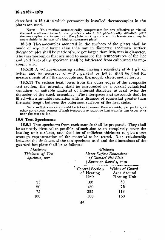
IS : 9162 - 1979
described in 16.4.8 in which permanently installed thermocouples in the plates are used.
NOTE -This method automatically compensates for any effective or virtual thermal resistance between the positions where the permanently installed plate thermocouples are located and the plate working surface. Such resistance may be appreciable in the case of a high-temperature plate.
16.5.9 Thermocouples mounted in the surfaces of the plates shall be made of wire not larger than 0.64 mm in diameter; specimen surface thermocouples shall be made of wire not larger than 0.46 mm in diameter. The thermocouples that are used to measure the temperatures of the hot and cold faces of the specimen shall be fabricated from calibrated thermo- couple wire.
X5.10 A voltage-measuring system having a sensitivity of & 1 PV or better and an accuracy of -& 0.1 percent or better shall be used for measurements of all thermocouple and thermopile electromotive forces.
16.5.11 To reduce heat losses from the outer edges of the composite test section, the assembly shall be surrounded by a coaxial cylindrical container of suitable material of internal diameter at least twice the diameter of the stack assembly. The interspaces and surrounds shall be filled with a suitable insulation within distance of somewhat greater than the axial length between the outermost surfaces of the heat sinks.
NOTE - Extreme care should be taken to ensure than no voids, gas pockets, or other extraneous sources of high-temperature radiative heat transfer can occur at or near the test section.
16.6 Test Specimens
16.6.1 Two specimens from each sample shall be prepared. They shall be as nearly identical as possible, of such size as to completely cover the heating unit surfaces, and shall be of sufficient thickness to give a true average representation of the material to be tested. The relationship between the thickness of the test specimen used and the dimensions of the guarded hot plate shall be as follows:
Maximum Minimum Thickness of Test Linear Surface Dimensions
Sfiecimen, mm of Guarded Hot Plate ( Square or Round ), mm
~-_----_-*- ___-_- 7 Central Section Width of Guard
of Heating Area Around Unit Heating Unit
33 100 50 50 150 75 75 225 113
100 300 150
52
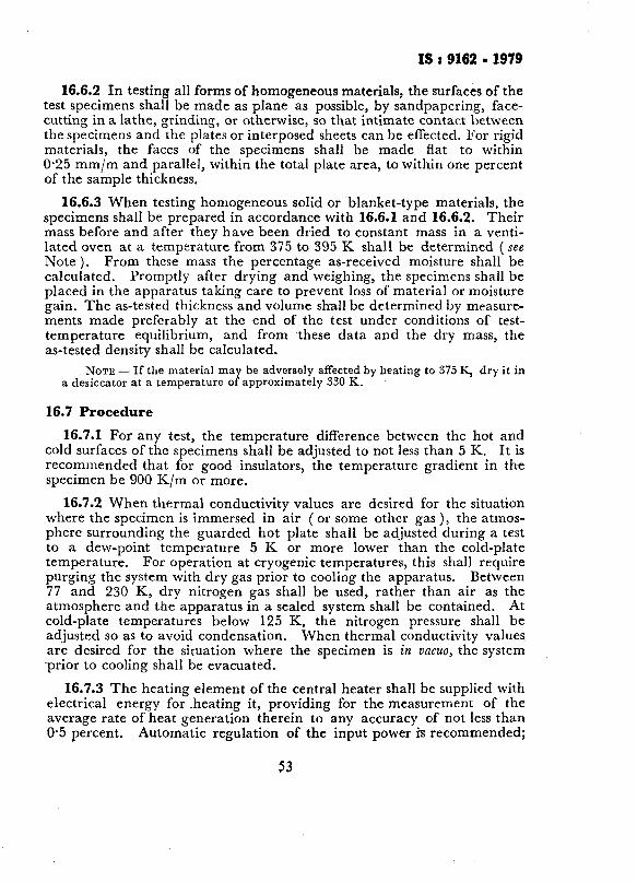
IS t 9162 - 1979
16.6.2 In testing all forms of homogeneous materials, the surfaces of the test specimens shall be mad-e as plane as possible, by sandpapering, face- cutting in a lathe, grinding, or otherwise, so that intimate contact between the specimens and the plates or interposed sheets can be effected. For rigid materials, the faces of the specimens shall be made flat to within O-25 mm/m and parallel, within the total plate area, to within one percent of the sample thickness,
16.6.3 When testing homogeneous solid or ~blanket-type materials, the specimens shall be prepared in accordance with 16.6.1 and 16.6.2. Their mass before and after they have been dried to constant mass in a venti- lated oven at a temperature from 375 to 395 K shall be determined ( see Note ). From these mass the percentage as-received moisture shall be calculated. Promptly after drying and weighing, the specimens shall be placed in the apparatus takin g care to prevent loss of material or moisture gain. The as-tested thickness and volume shall be determined by measure- ments made preferably at the end of the test under conditions of test- temperature equilibrium, and from these data and the dry mass, the as-tested density shall be calculated.
NOTE-If the material may be adversely affected by heating to 375 K, dry it in a desiccator at a temperature of approximately 330 K.
16.7 Procedure
16.7-l For any test, the temperature difference between the hot and cold surfaces of the specimens shall be adjusted to not less than 5 K. It is recommended that for good insulators, the temperature gradient in the specimen be 900 K/m or more.
16.7.2 When thermal conductivity values are desired for the situation where the specimen is immersed in air ( or some other gas ), the atmos- phere surrounding the guarded hot plate shall be adjusted during a test to a ~dew-point temperature 5 K or more lower than the cold-plate temperature. For operation at cryogenic temperatures, this shall require purging the system with dry gas prior to cooling the apparatus. Between 77 and 230 K, dry nitrogen gas shall be used, rather than air as the atmosphere and the apparatus in a sealed system shall be contained. At cold-plate temperatures below 125 K, the nitrogen pressure shall be adjusted so as to avoid condensation. When thermal conductivity values, are desired for the situation where the specimen is in vacua, the system ~prior to cooling shall be evacuated.
16.7.3 The heating element of the central heater shall be supplied with electrical energy for cheating it, providing for the measurement of the average rate of heat generation therein to any accuracy of not less than 0.5 percent. Automatic regulation of the input poweris recommended;

IS t 9162 - 1979
in any case, fluctuations or changes in input power shall not cause the temperature of the hot-plate surfaces to fluctuate, or to change in 1 hour of a test period, by more than 0.5 percent of the temperature difference between the hot and cold-plates. The input power shall be measured in such a way that the average power input during a test period can be determined; if the power input is of a fluctuating kind, an integrated energy measurement shall be made. The power input to the guard section shall be adjusted and maintained, preferably by automatic control, so as to effect the degree of temperature balance between the central and guard heater sections that is required for conformance to 16.4.4 to 16.5.4. For measurements at high temperatures, the power to the outer guard or cylindrical guard heater shall be adjusted, preferably by automatic control, so as to effect, for the test specimen, that the degree of temperature balance between the centre of the outer edge and the mean temperature conform to the conditions given in 16.4.11.
16.7.4 The cooling units or cold surface heaters shall be adjusted so that the temperature drops through the two specimens do not differ by more than 1 percent. The temperatures of the cooling plates or cold surface heaters, in the case of the high-temperature plate, during a test period shall not fluctuate or change, in 1 hour, by more than 0.5 percent of the temperature difference between the hot and cold surfaces of the specimen.
16.7.5 The temperature difference across the specimens, the hot and cold-plate temperatures, the centre-to-guard temperature balance, and the electrical power input to the central section shall be determined.
16.7.6 In order to attain the thermal conductivity value, it is essential to allow sufficient time for the apparatus and specimens to attain thermal equilibrium. The time required will depend on the specific apparatus, the control system and its operation, the test temperatures, and on the thermal diffusivity and thickness of the specimens. The observations given in 16.7.5 should be made at intervak of not less than 30 minutes until four successive sets of observations give thermal conductivity values differing by not more than 1 percent.
NOTE - Particularly in low temperature measurements on good insulators having low thermal diffusivities, the internal temperatures of the specimens can require a very long time to attain thermal equilibrium so that it is possible to have four consecutive 30-minutes tests which yield thermal conductivity values within 1 percent of each other and still not have steady-state conditions. Sufficient time should necessarily be allowed for the internal temperatures of the insulation to stabilize.
16.7.7 Particular care is indicated if a guarded hot-plate is used for measurements under vacuum conditions. If a hard vacuum is desired, materials shall be carefully selected to avoid excessive outgassing. Under
54
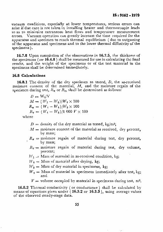
1s : 9162 - 1979
vacuum conditions, especially at lower temperatures, serious errors can arise if due care is not taken in installing heater and thermocouple leads so as to minimize extraneous heat flows and temperature measurement errors. Vacuum operation can greatly increase the time required for the apparatus and specimen to reach thermal equilibrium ( due to outgassing of the apparatus and specimens and to the lower thermal diffusivity of the specimens ) .
16.7.8 Upon completion of the observations in 16.7.5, the thickness of the specimens (see 16.4.8 ) shall be measured for use in calculating the final results, and the weight of the specimens or of the test material in the specimens shall be determined immediately.
16.8 Calculations
16.8.1 The density of the dry specimen as tested, D, the as-received moisture content of the material, A!f, and the moisture regain of the specimen during test, X, or R,, shall be determined as follows:
D = W2/V
M=(W1- W,)/Ws x 100
R, = ( W4 - W,)/W, x 100
R, = (Wd - W,)/l 000 V x loo where
D = density of the dry material as tested, kg/ms;
M = moisture content of the material as received, dry percent, by mass;
R, = moisture regain of material during test, dry percent, by mass;
R, -= moisture regain of material during test, dry volume, percent;
WI = Mass of material in as-received condition, kg;
W2 = Mass of material after drying, kg;
W3 = Mass of dry material in specimens, kg;
W4 = Mass of material in specimens immediately after test, kg; and
F’ = volume occupied by material in specimens during test, ms.
16.8.2 Thermal conductivity ( or conductance ) shall be calculated by means of equations given under ( 16.3.2 or 16.3.3 ), using average values of the observed steady-stage data.
55
1s : 9162 - 1939
16.9 Report
16.9.1 The report of the results of each test shall include the following ( the numerical values reported shall represent the average values for the two specimens as tested ):
a) b) 4 4 e) f >
Ed
h) j) k)
4 n)
Name and any other pertinent identification of the material;
Thickness of the specimen ( or material ) as tested, m;
Method and temperature of drying;
Density of the dry material as tested, kg/ms; As-received moisture content of the material, dry weight, percent;
Moisture regain of the material during test, dry weight percent or volume percent, or both; Average temperature gradient in the specimen during the test as computed from the temperatures of the hot and cold faces for the specific data point, K/m; Mean temperature of test, K; Heat flux through each specimen during test, W/ms;
Thermal conductivity, W/m.k or thermal conductance of specimen, W/m2.k; Orientation of the plane of the specimen : vertical or horizontal; For tests made, using sheet material interposed between the specimen and the plate surface, information as to the nature, thickness, and thermal conductance of the sheet material shall be given if separate thermocouples were used to determine the temperature drops in the specimens. Also information as to the size of the thermocouples, the method of affixing them to the specimen, and the measured distance between their centres shall be given;
p) Where appropriate to the condition and temperature of the test, the approximate resistance of the edge insulation and the ambient temperature surrounding the plate during the test, and also the duration of the measurement portion of the test; and
q) The vacuum reading or type and pressure of purge gas surround- ing the specimen.
16.9.2 Include a graphical representation of the results in the report when pertinent. This shall consist of a plot of each value of thermal conductivity obtained and the corresponding test mean temperature, plotted as ordinates and abscisses, respectively.
56

IS : 9162 - 1979
17. SHEAR STRENGTH
17.1 Object -To determine the shear strength of epoxy resin composition for floor topping.
17.2 Apparatus - In addition to those given in 7.2.1 to 7.2.4, the following shall also be provided.
17.2.1 Moulds - The moulds shall be made of hard metal not attacked by the composition. They shall be 10 cm or 15 cm cubes.
17.2.2 Universal Testing Machine - This shall be of at least 50 t capacity.
17.3 Composition Mix - The composition of mix shall be prepared as given in 17.4. 1 600 g compositions shall be used for preparing six composite cubes of 10 x 10 x 10 cm size and 3 800 g for 15 x 15 x 15 cm size.
17.4 Moulding of Test Specimen - Prepare at least six cement concrete epoxy resins mortars composites. The composite block shall be made up of old cement concrete block of 15 x 15 x 7.5 cm or 10 x 10 x 7.5 cm size topped with 2.5 cm of epoxy resins compositions under test, after an application of proper tack coat by the same formulation as used in the epoxy resins composition. First place the blocks or prisms in their respec- tive moulds, and then fill epoxy resins composition after proper tack coat application by using vertical strokes of a rammer. Strike off the excess mix and flush the surface by-trowel.
17.5 Condition of Test Specimen - The test specimen shall remain in respective moulds for a period of 24 hours after moulding.
17.6 Age - Age the test specimen for a period of 7 days in air at 27 & 2°C.
17.7 Procedure - Test six composite specimen at the end of the ageing period. The shear strength shall be the average of six composites. The testing procedure is given in Fig. 9, using Universal Testing Machine and keeping rate of loading as 14 N/mm* per minute.
17.8 Report - The shear strength shall be calculated from the load applied at failure over an average area. Express the result in N/mm2.
18. HYDROLYZABLE CHLORINE CONTENT OF LIQUID EPOXY RESIN
18.1 Object - This method covers the determination of the easily hydrolyzable chlorine content of liquid epoxy resin in concentration below 1 percent.
57

IS : 9162 - 1979
LOADING PLATE
150X75X 21*9 mm
PROP TRANSFERRING LOAD
150~75x234 mm ---II
75
1
INTENDED PLAN 3.1 -
OF SHEAR F
BASE PLATE
387.5xlSOx25mm
7
r COVER PLATE
278n734x25mm
CONCRETE PRISM
f
COVER PLATE
278x73.4x25mm
25mm @ HOLE
All dimensions in millimetres.
FIG. 9 SHEAR TEST APPARATUS
18.2 Apparatus
250-ml Erlenmeyer 18.2.1 I?eJlz~x A@aratus .- This shall consist of a flask equipped with a 24140 standard taper joint attached to a reflux condenser similarly equipped with a 24/40 standard taper joint and a hot- plate with variable heat control.
18.3 Chemicals and Reagents - The following reagent grade chemicals shall be used.
18.3.1 Standard Hvdrochloric Acid ( 0.1 N ) - Dilute 9 ml of concentra- ted hydrochloric ac;d to one litre of water. Standardize against 0.25 g of ~sodium carbonate, accurately weighed and dissolved in 75 to 100 ml of water.
58
IS : 9162.1979
18.3.2 Phenolphthalein Indicator - 1 g of phenolphthalein in 100 ml of methyl alcohol.
18.3.3 Potassium Hydroxide alcoholic solution ( 0.1 N) - 5.5 to 6 g of potassium hydroxide in 1 litre of methyl or ethyl alcohol.
18.3.4 Toluene
18.4 Procedure
18.4.1 Weigh 6 to 8 g of neutral sample into a 250-ml glass-stoppered Erlenmeyer flask. By means of a pipette, transfer 50 ml of O-1 N alcoholic potassium hydroxide solution into the flask and add from a graduated cylinder, 15 ml of toluene. Stopper the flask and swirl to mix. Add a few boiling aids and attach to the reflux condenser on the hot plate.
18.4.2 Allow the solution to reflux gently for 15 f 1 minutes. At the end of the reflux period, remove the flask from the hot-plate and cool to 27 + 2°C with the condenser in place.
18.4.3 Remove the condenser and add 3 drops of phenolphthalein indicator solutions to the sample and titrate with 0.1 N hydrochloric acid. The point is taken when 1 drop changes the solution from pink to colourless.
NOTE - Add 100 ml of methyl ethyl ketone to the sample if required to ensure homogeneous solution during titration of excess potassium hydroxide solution.
18.4.4 Make a blank determination on the reagents following the same procedure but omitting the sample.
18.4.5 Calculation Hydrolyzable chlorine content, - [ (B- V).N x 3.55 I/S
percent by mass where
B = volume of hydrochloric acid required for titration of the blank, ml;
V = volume of hydrochloric acid required for titration of sample, ml;
.N = normality of hydrochloric acid; and s = mass of sample, g.
59
IS : 9162 - 1979
APPEN.DIX 4 (Clauses 15.3.1 and 15.4.1 )
ESSENTIAL REQUIREMENTS OF THE ABRASION TESTING MACHINE
A-I. GENERAL
A-l.1 The testing apparatus shall be ~a grinding device consisting essentially of a horizontally fixed smooth grinding disc of about 750 mm diameter rotating about a vertical axis and furnished with a replaceable grinding path. The essential features are shown in Fig. 10.
A-2. GRINDING PATH
A-2.1 Cast iron shall be used as material for the grinding path. Its scaleroscope hardness shall lie between 30 and 50. This hardness shall be ascertained at least 10 times on the rim and at several points in the grinding path by means of a Shore’s scaleroscope with diamond hammer.
A-2.2 The grinding path shall be a 200 mm wide annular space on the grinding disc between distances of 120 and 320 mm from the centre. The grinding path shall be repaired and restored when it has worn out ~by more than 0.5 mm after use or when the furrows formed in it exceed 0.2 mm in depth. When the grinding path is restored, its hardness shall be determined afresh.
A-3. ROTATION OF DISC
A-3.1 The disc shall be driven at 30 rev/min. The speed of rotation shall not deviate by more than one revolution per minute. There shall be auto- matic mechanisms for counting, indicating the revolutions of the disc and for stopping the disc after every 22 revolutions. Such mechanisms shall be checked for reliability prior to the test.
A-4. HOLDING DEVICE FOR TEST SPECIMEN
A-4.1 The holding device shall consist of a square frame, open on one side and made of cast-iron or steel; it shall be of about 40 mm height, with its lower edge about 5 mm above the surface of the grinding disc and so positioned that its centre is at a distance of 220 mm from the centre of the disc. It shall necessarily, but loosely, hold the specimen.
A-5. LOADING DEVICE
A-5.1 The loading device shall consist of a steel lever. A short arm of the lever shall be provided with a counter weight just to balance the weight of the long arm and of the weighing disc, so that the pressure stamp just touches the specimen prior to the loading.
60
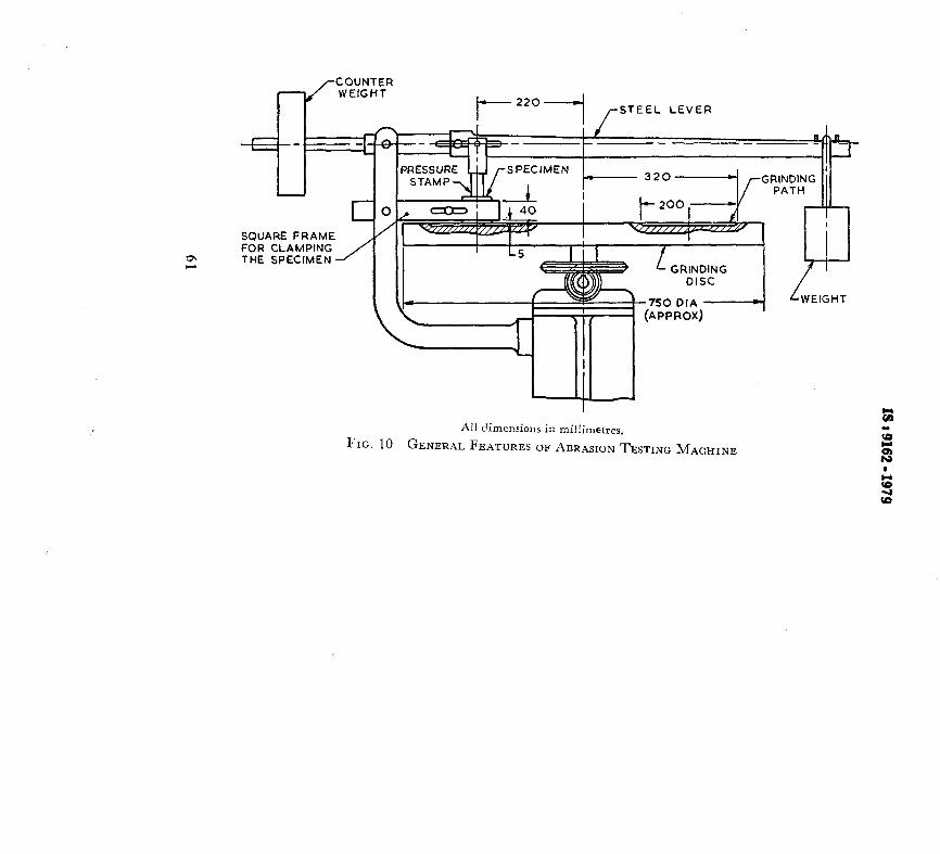
COUNTER WEfCHT
I-““I /-STEEL LEVER
D”“WKC r-r(HMC
FOR CLAMPING THE SPECIMEN
,so ,p,‘“‘I r’,E,GHT
APPROX)
All dimensions in millimetres.
FIG. 10 GENERAL FEATURES OF ABRASION TESTING MACHIXE
?

18 t 9132 - 1979
A-5.2 The lever shall move freely about the fulcrum without appreciable friction. Durin.g test, the lever shall remain nearly parallel to the upper surface of the disc. The connection of the pressure stamp to the lever shall be through a self-aligning joint permitting free relative movement but at the same time ensuring a central load on the specimen being tested.
A-5.3 Suitable loading weight shall be applied at the end of the long arm of the lever so that, as magnified by the leverage, a net load of 300 N is applied through the pressure stamp on to the specimen. The load shall be applied with a permissible deviation of one percent. The accuracy of the load shall be verified both by calculation and by measurement with suitable instruments.
APPENDIX B
( czause 15.3.1 )
SPECIFICATION OF ABRASIVE POWDER
B-l. CHEMICAL COMPOSITION
B-l.1 The abrasive powder shall have an aluminium oxide content of not less than 95 percent by mass.
iVo!rE - While otherwise conforming to the specification, synthetic aluminium oxide is normally employed for the test.
B-2. SHAPE AND SIZE
B-2.1 The grains shall be of rounded shape and shall generally pass through IS Test Sieve 250 pm and be retained on IS Test Sieve 212 pm. The combined content of larger grains retained on IS Test Sieve 250 pm and of smaller grains whose fineness is not limited, shall not exceed 10 percent.
B-3. SPECIFIC GRAVITY
B-3.1 The specific gravity of the grains shall be between 3.93 and 4.1.
B-4. HARDNESS
B-4.1 The grains shall generally have a hardness of 9 in Moh’s scale.
62

INDIAN STANDARDS
ON
FLOORING AND PLASTERING
IS :
653-1962
657-1962
658-1962
809-1970
1195-1978
1196-1978
1197-1970
1198-1958
1237-1959
1443-1972
1542-1977
1630-1960
1661-1972
2114-1962
2394-1965
2402-1963 2571-1970
3461-1966
3462-1966
3463-1966
3464-1966
4112-1967
4441-1967
4442-1967
4443-l 967
Sheet linoleum ( revised )
Materials for use in the manufacture of magnesium oxychloride flooring compositions ( revised)
Code of practice for magnesium oxychloride composition floors ( revised )
Rubber flooring materials for general purposes (jirst revision )
Bitumen mastic for flooring ( second revision )
Code of practice for laying bitumen mastic flooring ( second revision )
Code of practice for laying of rubber floors (jrst reuision )
Code of practice for laying and maintenance of linoleum floor
Cement concrete flooring tiles
Code of practice for laying and finishing of cement concrete flooring tiles ( jirst revision )
Sand for plaster (Jlrsl revision )
Mason’s tools for plaster work and pointing work
Code of practice for application of cement and cement lime plaster finish (first revision )
Code of practice for laying in-situ terrazzo floor finish
Code of practice for application of lime plaster finish
Code of practice for external rendered finishes Code of practice for laying in-situ cement concrete flooring (first revision)
PVC ( vinyl ) asbestos floor tiles
Flexible PVC flooring
Polystyrene wall tiles
Methods of test for plastic flooring and wall tiles
Code of practice for fixing of polystyrene wall tiles
Code of practice for use of silicate type chemical resistant mortars
Code of practice for use of sulphur type chemical resistant mortars
Code of practice for use of resin type chemical resistant mortars
4456 ( Part I )-1967 Methods of test for chemical resistant mortars : Part I Silicate type and resin type
4456 ( Part II )-1967 Methods of test for chemical resistant mortars : Part II Sulphur type
4457-1967 Ceramic unglazed vitreous acid-resistant tiles
4631-1968 Code of practice for laying of epoxy resin floor toppings
4832 ( Part I )-I969 Chemical resistant mortars : Part I Silicate type
4832 ( Part II )-1969 Chemical resistant mortars : Part II Resin type
4832 ( Part III )-1968 Chemical resistant~mortars : Part III Sulphur type
4860-1968 Acid-resistant bricks
IS:
4971-1968 Recommendations for selection of industrial floor finishes
5317-1969 Bitumen mastic for bridge decking and roads
5318-1969 Code of practice for laying of flexible PVC sheets and tile flooring
5491-l969 Code of practice for laying in-A granolithic concrete floor topping
1 5766-1970 Code of practice for laying burnt clay brick flooring
6278-1971 Code of practice for white-washing and colour washing
7956-1975 Recommendations for selection of dairy floor finishes
8374-1977 Bitumen-mastic, anti-static and electrically conducting grade
9197-1979 Epoxy resins and epoxy resins compositions for floor toppings