is7 profinet user manual - lsis
TRANSCRIPT
www.lsis.com
iS7 PROFInet User Manual
iS7 PROFInet Option Manual
i
Safety Precaution
First thank you for using our iS7 PROFInet Option Board!
Please follow the following safety attentions since they are intended to prevent any possible accident and danger so that you can use this product safely and correctly.
Safety attentions may classify into ‘Warning’ and ‘Caution’ and their meaning is as following:
Symbol Meaning
WARNING
This symbol indicates the possibility of death or serious injury.
CAUTION
This symbol indicates the possibility of injury or damage to property.
1. The meaning of each symbol in this manual and on your equipment is as follows.
Symbol Meaning
This is the safety alert symbol.
Read and follow instructions carefully to avoid dangerous situation.
This symbol alerts the user to the presence of “dangerous voltage” inside the product that might cause harm or electric shock.
After reading this manual, keep it in the place that the user always can contact. This manual should be given to the person who actually uses the products and is responsible for their maintenance.
ii
WARNING
Do not remove the cover while power is applied or the unit is in operation.
Otherwise, electric shock could occur.
Do not run the inverter with the front cover removed.
Otherwise, you may get an electric shock due to high voltage terminals or charged capacitor exposure.
Do not remove the cover except for periodic inspections or wiring, even if the input power is not applied.
Otherwise, you may access the charged circuits and get an electric shock.
Wiring and periodic inspections should be performed at least 10 minutes after disconnecting the input power and after checking the DC link voltage is discharged with a meter (below DC 30V).
Otherwise, you may get an electric shock.
Operate the switches with dry hands.
Otherwise, you may get an electric shock.
Do not use the cable when its insulating tube is damaged.
Otherwise, you may get an electric shock.
Do not subject the cables to scratches, excessive stress, heavy loads or pinching.
Otherwise, you may get an electric shock.
CAUTION
Be cautious when handling CMOS elements on the option board.
It may cause a failure due to static electricity.
When changing and connecting communication signal lines, proceed the work while the inverter is turned off.
It may cause a communication error or failure.
Make sure to connect the inverter body to the option board connector accurately coincided each other.
It may cause a communication error or failure.
Make sure to check the parameter unit when setting parameters.
It may cause a communication error.
iS7 PROFInet Option Manual
iii
Table of Contens
1 About the Product ........................................................................................... 4
1.1 Included Items ........................................................................................ 4
1.2 PROFInet Technical Features ................................................................. 4
1.3 GSDML File ............................................................................................ 4
2 Part Names and Installation ............................................................................ 5
2.1 Exterior ................................................................................................... 5
2.2 Installing the PROFInet Communication Module ..................................... 5
2.3 PROFInet Communication Module Front Panel ...................................... 6
2.4 24 V External Power Input ...................................................................... 8
3 Network Connections ..................................................................................... 11
3.1 Network Cable Contacts ........................................................................ 11
3.2 Communication Cable Connector .......................................................... 11
3.3 Network Cable Specification .................................................................. 11
4 PROFInet Communication Related Keypad Parameters ............................. 12
5 Keypad Parameters Related to PROFInet Communication Module ........... 14
5.1 CNF Group ........................................................................................... 14
5.2 DRV Group ........................................................................................... 14
5.3 COM Group .......................................................................................... 15
5.4 PRT Group ............................................................................................ 17
6 PROFIdrive Status Diagram .......................................................................... 18
7 Supported PROFIdrive Cyclic Telegram ...................................................... 20
7.1 Standard Telegram (Mode : 0) .............................................................. 20
7.2 Vendor Specific Telegram (Mode : 1) .................................................... 20
8 Supported PROFIdrive Parameters .............................................................. 26
9 Fault Message Counter (PNU[944]) and Fault Number (PNU[947]) ............ 28
10 Accessing the iS7 Common Parameters using the PROFIdrive Parameters ........................................................................................................................ 32
11 Accessing iS7 Inverter Parameters using the PROFInet Record Data Object ............................................................................................................. 34
12 Processing the Alarms .................................................................................. 35
13 Trouble Shooting ........................................................................................... 36
iS7 PROFInet Option Manual
4
1 About the Product
The LSIS iS7 PROFInet communication module (model CJ-S7M1) provides PROFInet network communication for the SV-iS7 inverter. PROFInet is a communication protocol compliant with IEC 61158 Type 10. The PROFInet communication module provides full-duplex data transfer which enables real-time communication without transmission collisions. Using a PROFInet connection, the iS7 inverter can be controlled and monitored via a PLC sequence program or any master PLC module. In addition, PROFInet is easy to connect, enabling faster installation and easier maintenance.
1.1 Included Items
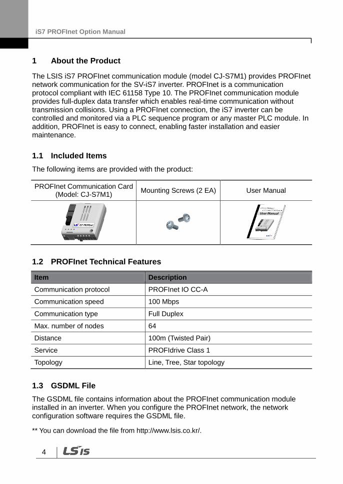
The following items are provided with the product:
PROFInet Communication Card (Model: CJ-S7M1)
Mounting Screws (2 EA) User Manual
1.2 PROFInet Technical Features
Item Description
Communication protocol PROFInet IO CC-A
Communication speed 100 Mbps
Communication type Full Duplex
Max. number of nodes 64
Distance 100m (Twisted Pair)
Service PROFIdrive Class 1
Topology Line, Tree, Star topology
1.3 GSDML File
The GSDML file contains information about the PROFInet communication module installed in an inverter. When you configure the PROFInet network, the network configuration software requires the GSDML file.
** You can download the file from http://www.lsis.co.kr/.
iS7 PROFInet Option Manual
5
2 Part Names and Installation
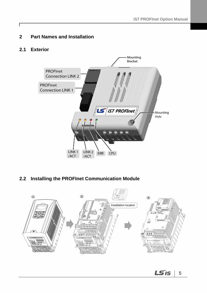
2.1 Exterior
2.2 Installing the PROFInet Communication Module
Installation location
iS7 PROFInet Option Manual
6
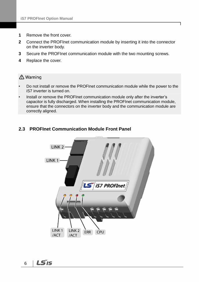
1 Remove the front cover.
2 Connect the PROFInet communication module by inserting it into the connector on the inverter body.
3 Secure the PROFInet communication module with the two mounting screws.
4 Replace the cover.
• Do not install or remove the PROFInet communication module while the power to the iS7 inverter is turned on.
• Install or remove the PROFInet communication module only after the inverter’s capacitor is fully discharged. When installing the PROFInet communication module, ensure that the connectors on the inverter body and the communication module are correctly aligned.
2.3 PROFInet Communication Module Front Panel
iS7 PROFInet Option Manual
7
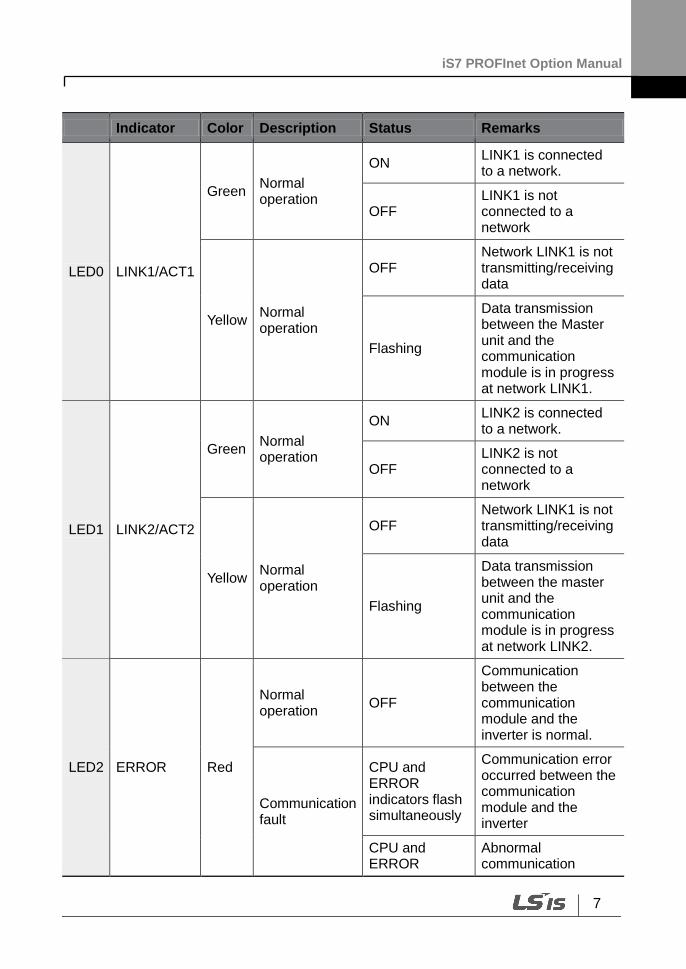
Indicator Color Description Status Remarks
LED0 LINK1/ACT1
Green Normal operation
ON LINK1 is connected to a network.
OFF LINK1 is not connected to a network
Yellow Normal operation
OFF Network LINK1 is not transmitting/receiving data
Flashing
Data transmission between the Master unit and the communication module is in progress at network LINK1.
LED1 LINK2/ACT2
Green Normal operation
ON LINK2 is connected to a network.
OFF LINK2 is not connected to a network
Yellow Normal operation
OFF Network LINK1 is not transmitting/receiving data
Flashing
Data transmission between the master unit and the communication module is in progress at network LINK2.
LED2 ERROR Red
Normal operation
OFF
Communication between the communication module and the inverter is normal.
Communication fault
CPU and ERROR indicators flash simultaneously
Communication error occurred between the communication module and the inverter
CPU and ERROR
Abnormal communication

iS7 PROFInet Option Manual
8
Indicator Color Description Status Remarks
indicators flash asynchronously, in 2 second intervals
conditions exist between the communication module and the inverter.
ON The communication module failed to boot up.
LED3 CPU Green
Abnormal operation
ON The CPU is not operating. OFF
Normal operation
Flashing (1 second intervals)
The communication module is installed correctly in the inverter.
2.4 24 V External Power Input
Pin No. Name Description
1 +24 V 24 V External Power (+)
2 GND 24 V External Power (-)
3 P.E Protective Earth for 24 V External Power
* The topmost pin is Pin #1 in the following illustration.
* Rated Power (Power Consumption): 1.3 W
iS7 PROFInet Option Manual
9
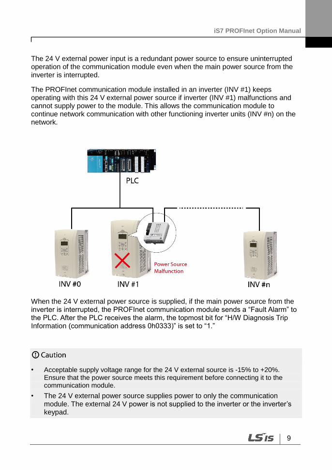
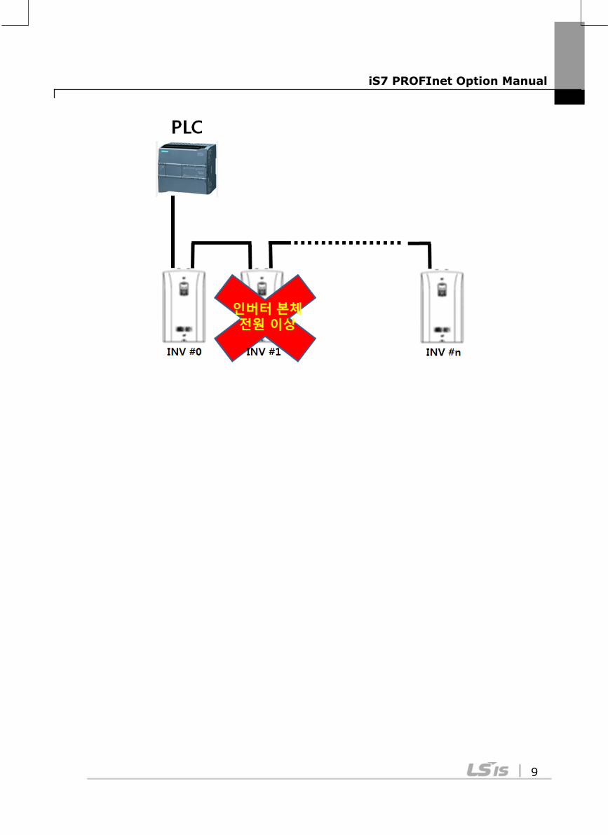
The 24 V external power input is a redundant power source to ensure uninterrupted operation of the communication module even when the main power source from the inverter is interrupted.
The PROFInet communication module installed in an inverter (INV #1) keeps operating with this 24 V external power source if inverter (INV #1) malfunctions and cannot supply power to the module. This allows the communication module to continue network communication with other functioning inverter units (INV #n) on the network.
When the 24 V external power source is supplied, if the main power source from the inverter is interrupted, the PROFInet communication module sends a “Fault Alarm” to the PLC. After the PLC receives the alarm, the topmost bit for “H/W Diagnosis Trip Information (communication address 0h0333)” is set to “1.”
• Acceptable supply voltage range for the 24 V external source is -15% to +20%. Ensure that the power source meets this requirement before connecting it to the communication module.
• The 24 V external power source supplies power to only the communication module. The external 24 V power is not supplied to the inverter or the inverter’s keypad.

iS7 PROFInet Option Manual
10
iS7 PROFInet Option Manual
11
3 Network Connections
3.1 Network Cable Contacts
Pin No. Signal Description Cable Color
1 TX+ Data Transmission (+) White/Yellow
2 TX- Data Transmission (-) Yellow
3 RX+ Data Reception (+) White/Green
4 NONE Not Used Blue
5 NONE Not Used White/Blue
6 RX- Data Reception (-) Green
7 NONE Not Used White/Brown
8 NONE Not Used Brown
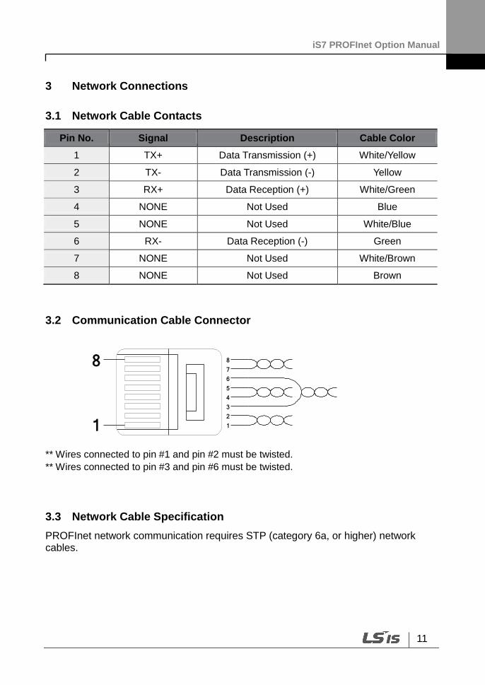
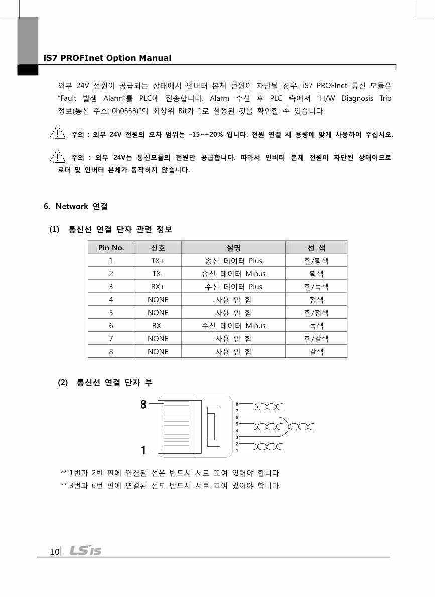
3.2 Communication Cable Connector
** Wires connected to pin #1 and pin #2 must be twisted.
** Wires connected to pin #3 and pin #6 must be twisted.
3.3 Network Cable Specification
PROFInet network communication requires STP (category 6a, or higher) network cables.
1
8
1
2
3
4
5
6
7
8
iS7 PROFInet Option Manual
12
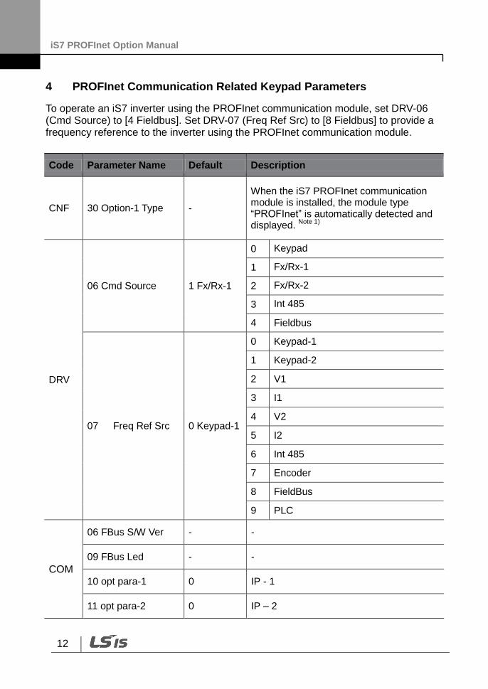
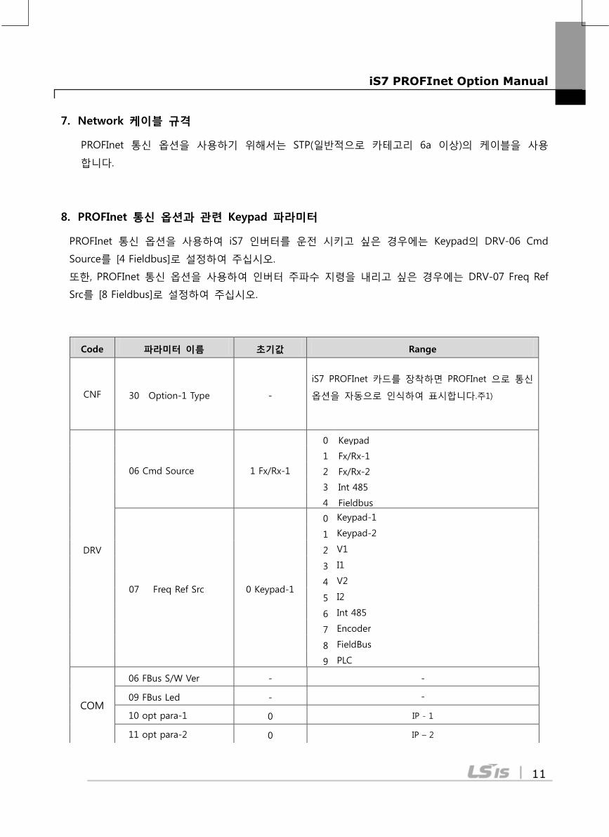
4 PROFInet Communication Related Keypad Parameters
To operate an iS7 inverter using the PROFInet communication module, set DRV-06 (Cmd Source) to [4 Fieldbus]. Set DRV-07 (Freq Ref Src) to [8 Fieldbus] to provide a frequency reference to the inverter using the PROFInet communication module.
Code Parameter Name Default Description
CNF 30 Option-1 Type -
When the iS7 PROFInet communication module is installed, the module type “PROFInet” is automatically detected and displayed.
Note 1)
DRV
06 Cmd Source 1 Fx/Rx-1
0 Keypad
1 Fx/Rx-1
2 Fx/Rx-2
3 Int 485
4 Fieldbus
07 Freq Ref Src 0 Keypad-1
0 Keypad-1
1 Keypad-2
2 V1
3 I1
4 V2
5 I2
6 Int 485
7 Encoder
8 FieldBus
9 PLC
COM
06 FBus S/W Ver - -
09 FBus Led - -
10 opt para-1 0 IP - 1
11 opt para-2 0 IP – 2
iS7 PROFInet Option Manual
13
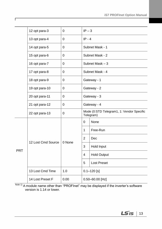
Note 1) A module name other than “PROFInet” may be displayed if the inverter’s software
version is 1.14 or lower.
12 opt para-3 0 IP – 3
13 opt para-4 0 IP - 4
14 opt para-5 0 Subnet Mask - 1
15 opt para-6 0 Subnet Mask - 2
16 opt para-7 0 Subnet Mask – 3
17 opt para-8 0 Subnet Mask - 4
18 opt para-9 0 Gateway - 1
19 opt para-10 0 Gateway - 2
20 opt para-11 0 Gateway - 3
21 opt para-12 0 Gateway - 4
22 opt para-13 0 Mode (0:STD Telegram1, 1: Vendor Specific Telegram)
PRT
12 Lost Cmd Source 0 None
0 None
1 Free-Run
2 Dec
3 Hold Input
4 Hold Output
5 Lost Preset
13 Lost Cmd Time 1.0 0.1–120 [s]
14 Lost Preset F 0.00 0.50–60.00 [Hz]
iS7 PROFInet Option Manual
14
5 Keypad Parameters Related to PROFInet Communication Module
5.1 CNF Group
5.1.1 [CNF-30] Option-1 Type: the type of device installed in the module slot 1
Automatically detects and displays the type of communication module installed. “PROFInet” is displayed when a PROFInet communication module is installed in the iS7 inverter.
5.2 DRV Group
5.2.1 [DRV-06] Cmd Source: Command Source Selection
Selects the command source for the iS7 inverter. Set the parameter to [4 FieldBus] to set PROFInet communication as the command source.
5.2.2 [DRV-07] Freq Ref Src: Frequency Reference Source Selection
Selects the frequency reference source for the iS7 inverter. Set the parameter to [8 FieldBus] to set PROFInet communication as the frequency reference source.
iS7 PROFInet Option Manual
15
5.3 COM Group
5.3.1 [COM-06] FBus S/W Ver: Communication Module Software Version
Automatically detects and displays the software version of the currently installed communication module.
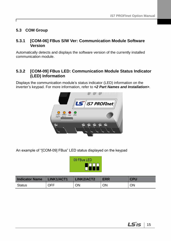
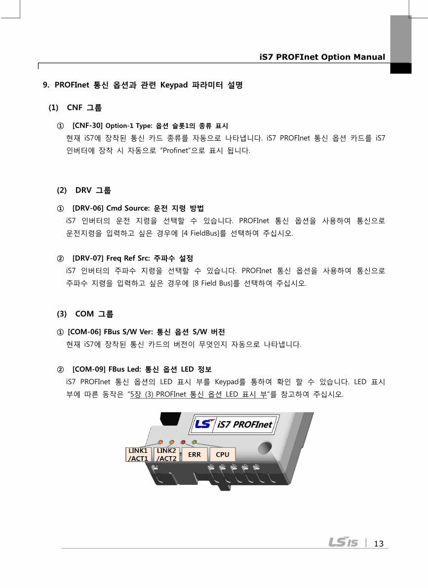
5.3.2 [COM-09] FBus LED: Communication Module Status Indicator (LED) Information
Displays the communication module’s status indicator (LED) information on the inverter’s keypad. For more information, refer to <2 Part Names and Installation>.
An example of “[COM-09] FBus” LED status displayed on the keypad
Indicator Name LINK1/ACT1 LINK2/ACT2 ERR CPU
Status OFF ON ON ON
iS7 PROFInet Option Manual
16
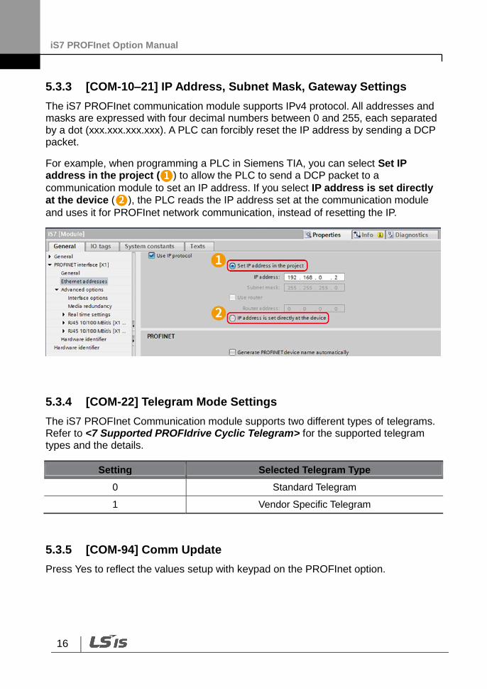
5.3.3 [COM-10–21] IP Address, Subnet Mask, Gateway Settings
The iS7 PROFInet communication module supports IPv4 protocol. All addresses and masks are expressed with four decimal numbers between 0 and 255, each separated by a dot (xxx.xxx.xxx.xxx). A PLC can forcibly reset the IP address by sending a DCP packet.
For example, when programming a PLC in Siemens TIA, you can select Set IP address in the project ( ) to allow the PLC to send a DCP packet to a
communication module to set an IP address. If you select IP address is set directly at the device ( ), the PLC reads the IP address set at the communication module
and uses it for PROFInet network communication, instead of resetting the IP.
5.3.4 [COM-22] Telegram Mode Settings
The iS7 PROFInet Communication module supports two different types of telegrams. Refer to <7 Supported PROFIdrive Cyclic Telegram> for the supported telegram types and the details.
Setting Selected Telegram Type
0 Standard Telegram
1 Vendor Specific Telegram
5.3.5 [COM-94] Comm Update
Press Yes to reflect the values setup with keypad on the PROFInet option.
iS7 PROFInet Option Manual
17
5.4 PRT Group
5.4.1 [PRT-12] Lost Cmd Mode: Lost Command Mode Options
Select the inverter’s operation mode for a “Lost Command” condition caused by a communication error.
The following table lists available operation modes.
Settings Description
0 None Speed reference becomes the operating frequency, without a protective operation.
1 Free-Run The inverter cuts off the output and the motor free-runs.
2 Dec The inverter performs a deceleration stop according to the time set at “Trip Dec Time.”
3 Hold Input The inverter keeps operating using the speed reference received before the command loss.
4 Hold Output The inverter keeps operating using the operation frequency it was operating at before the command loss.
5 Lost Preset The inverter operates using the frequency reference set at Pr-14 “Lost Preset F.”
5.4.2 [PRT-13] Lost Cmd Time: Lost Command Decision Time
Sets the time taken for the inverter to decide that a command has been lost, and apply the “Lost Command Modes” set at [PRT-12]. The setting range is from 0.1–120 seconds.
5.4.3 [PRT-14] Lost Preset F: Frequency Reference for Lost Command
Sets a protective function that allows the inverter to run at a frequency reference that is pre-set at [PRT-14], when command via the communication module is lost. The setting range is between the start frequency and the maximum frequency [Hz].
iS7 PROFInet Option Manual
18
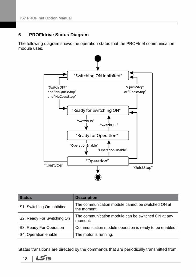
6 PROFIdrive Status Diagram
The following diagram shows the operation status that the PROFInet communication module uses.
Status Description
S1: Switching On Inhibited The communication module cannot be switched ON at the moment.
S2: Ready For Switching On The communication module can be switched ON at any moment.
S3: Ready For Operation Communication module operation is ready to be enabled.
S4: Operation enable The motor is running.
Status transitions are directed by the commands that are periodically transmitted from
iS7 PROFInet Option Manual
19
the PLC, and the command types are as follows. Refer to <7.2.1 Control word (STW1)> for more information.
• NoQuickStop Command
• NoCoastStop Command
• SwitchOFF Command
• SwitchON Command
• OperationEnable Command
• OperationDisable Command
• QuickStop Command
• CoastStop Command
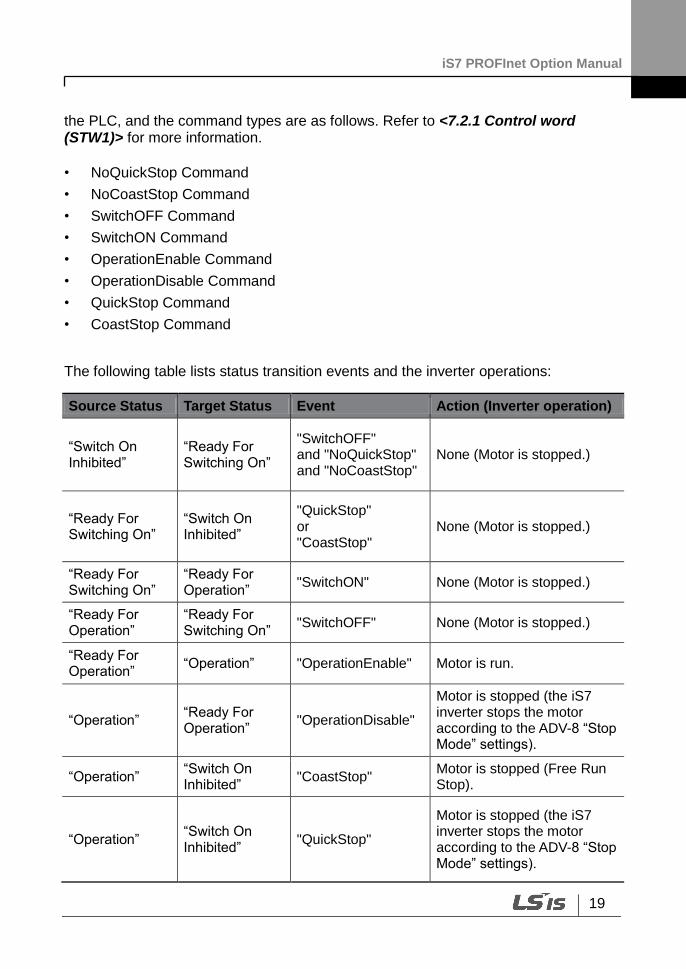
The following table lists status transition events and the inverter operations:
Source Status Target Status Event Action (Inverter operation)
“Switch On Inhibited”
“Ready For Switching On”
"SwitchOFF" and "NoQuickStop" and "NoCoastStop"
None (Motor is stopped.)
“Ready For Switching On”
“Switch On Inhibited”
"QuickStop" or "CoastStop"
None (Motor is stopped.)
“Ready For Switching On”
“Ready For Operation”
"SwitchON" None (Motor is stopped.)
“Ready For Operation”
“Ready For Switching On”
"SwitchOFF" None (Motor is stopped.)
“Ready For Operation”
“Operation” "OperationEnable" Motor is run.
“Operation” “Ready For Operation”
"OperationDisable"
Motor is stopped (the iS7 inverter stops the motor according to the ADV-8 “Stop Mode” settings).
“Operation” “Switch On Inhibited”
"CoastStop" Motor is stopped (Free Run Stop).
“Operation” “Switch On Inhibited”
"QuickStop"
Motor is stopped (the iS7 inverter stops the motor according to the ADV-8 “Stop Mode” settings).
iS7 PROFInet Option Manual
20
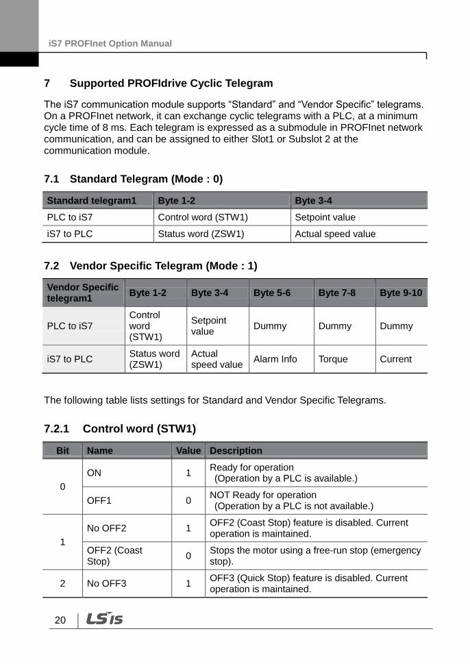
7 Supported PROFIdrive Cyclic Telegram
The iS7 communication module supports “Standard” and “Vendor Specific” telegrams. On a PROFInet network, it can exchange cyclic telegrams with a PLC, at a minimum cycle time of 8 ms. Each telegram is expressed as a submodule in PROFInet network communication, and can be assigned to either Slot1 or Subslot 2 at the communication module.
7.1 Standard Telegram (Mode : 0)
Standard telegram1 Byte 1-2 Byte 3-4
PLC to iS7 Control word (STW1) Setpoint value
iS7 to PLC Status word (ZSW1) Actual speed value
7.2 Vendor Specific Telegram (Mode : 1)
Vendor Specific telegram1
Byte 1-2 Byte 3-4 Byte 5-6 Byte 7-8 Byte 9-10
PLC to iS7 Control word (STW1)
Setpoint value
Dummy Dummy Dummy
iS7 to PLC Status word (ZSW1)
Actual speed value
Alarm Info Torque Current
The following table lists settings for Standard and Vendor Specific Telegrams.
7.2.1 Control word (STW1)
Bit Name Value Description
0
ON 1 Ready for operation (Operation by a PLC is available.)
OFF1 0 NOT Ready for operation (Operation by a PLC is not available.)
1
No OFF2 1 OFF2 (Coast Stop) feature is disabled. Current operation is maintained.
OFF2 (Coast Stop)
0 Stops the motor using a free-run stop (emergency stop).
2 No OFF3 1 OFF3 (Quick Stop) feature is disabled. Current operation is maintained.
iS7 PROFInet Option Manual
21
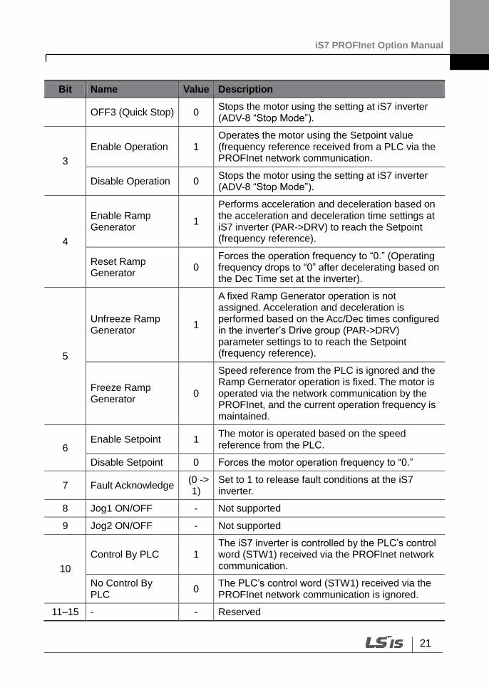
Bit Name Value Description
OFF3 (Quick Stop) 0 Stops the motor using the setting at iS7 inverter (ADV-8 “Stop Mode”).
3
Enable Operation 1 Operates the motor using the Setpoint value (frequency reference received from a PLC via the PROFInet network communication.
Disable Operation 0 Stops the motor using the setting at iS7 inverter (ADV-8 “Stop Mode”).
4
Enable Ramp Generator
1
Performs acceleration and deceleration based on the acceleration and deceleration time settings at iS7 inverter (PAR->DRV) to reach the Setpoint (frequency reference).
Reset Ramp Generator
0 Forces the operation frequency to “0.” (Operating frequency drops to “0” after decelerating based on the Dec Time set at the inverter).
5
Unfreeze Ramp Generator
1
A fixed Ramp Generator operation is not assigned. Acceleration and deceleration is performed based on the Acc/Dec times configured in the inverter’s Drive group (PAR->DRV) parameter settings to to reach the Setpoint (frequency reference).
Freeze Ramp Generator
0
Speed reference from the PLC is ignored and the Ramp Gernerator operation is fixed. The motor is operated via the network communication by the PROFInet, and the current operation frequency is maintained.
6 Enable Setpoint 1
The motor is operated based on the speed reference from the PLC.
Disable Setpoint 0 Forces the motor operation frequency to “0.”
7 Fault Acknowledge (0 ->
1) Set to 1 to release fault conditions at the iS7 inverter.
8 Jog1 ON/OFF - Not supported
9 Jog2 ON/OFF - Not supported
10
Control By PLC 1 The iS7 inverter is controlled by the PLC’s control word (STW1) received via the PROFInet network communication.
No Control By PLC
0 The PLC’s control word (STW1) received via the PROFInet network communication is ignored.
11–15 - - Reserved
iS7 PROFInet Option Manual
22
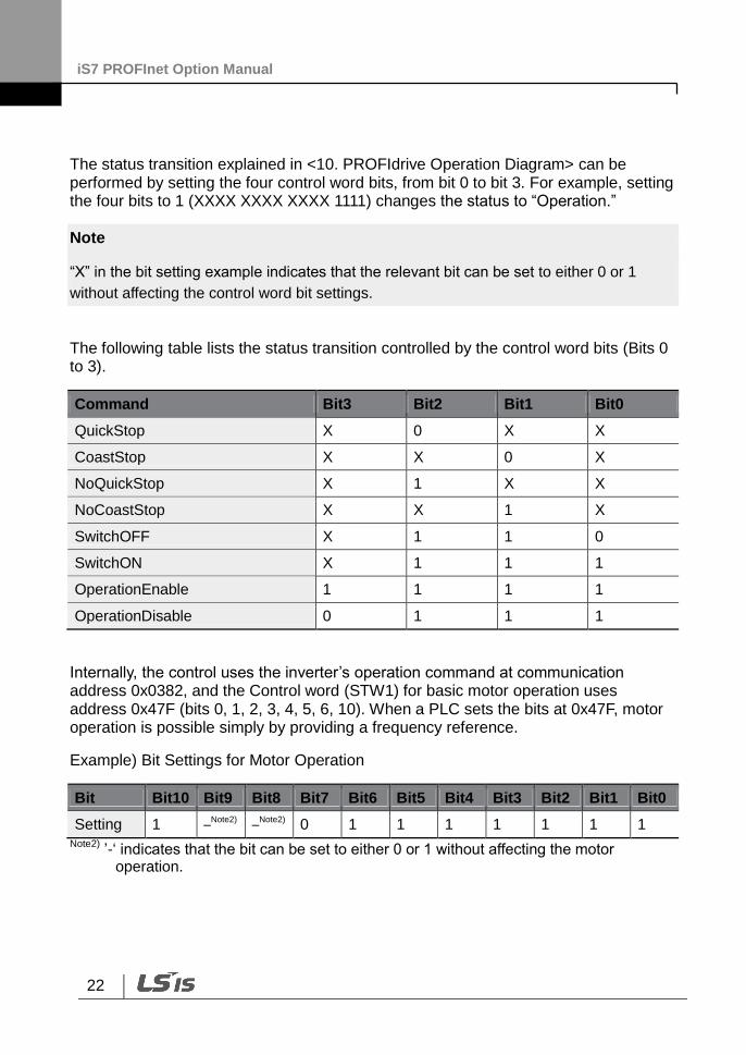
The status transition explained in <10. PROFIdrive Operation Diagram> can be performed by setting the four control word bits, from bit 0 to bit 3. For example, setting the four bits to 1 (XXXX XXXX XXXX 1111) changes the status to “Operation.”
Note
“X” in the bit setting example indicates that the relevant bit can be set to either 0 or 1
without affecting the control word bit settings.
The following table lists the status transition controlled by the control word bits (Bits 0 to 3).
Command Bit3 Bit2 Bit1 Bit0
QuickStop X 0 X X
CoastStop X X 0 X
NoQuickStop X 1 X X
NoCoastStop X X 1 X
SwitchOFF X 1 1 0
SwitchON X 1 1 1
OperationEnable 1 1 1 1
OperationDisable 0 1 1 1
Internally, the control uses the inverter’s operation command at communication address 0x0382, and the Control word (STW1) for basic motor operation uses address 0x47F (bits 0, 1, 2, 3, 4, 5, 6, 10). When a PLC sets the bits at 0x47F, motor operation is possible simply by providing a frequency reference.
Example) Bit Settings for Motor Operation
Bit Bit10 Bit9 Bit8 Bit7 Bit6 Bit5 Bit4 Bit3 Bit2 Bit1 Bit0
Setting 1 –Note2)
–Note2)
0 1 1 1 1 1 1 1 Note2)
’-‘ indicates that the bit can be set to either 0 or 1 without affecting the motor operation.
iS7 PROFInet Option Manual
23
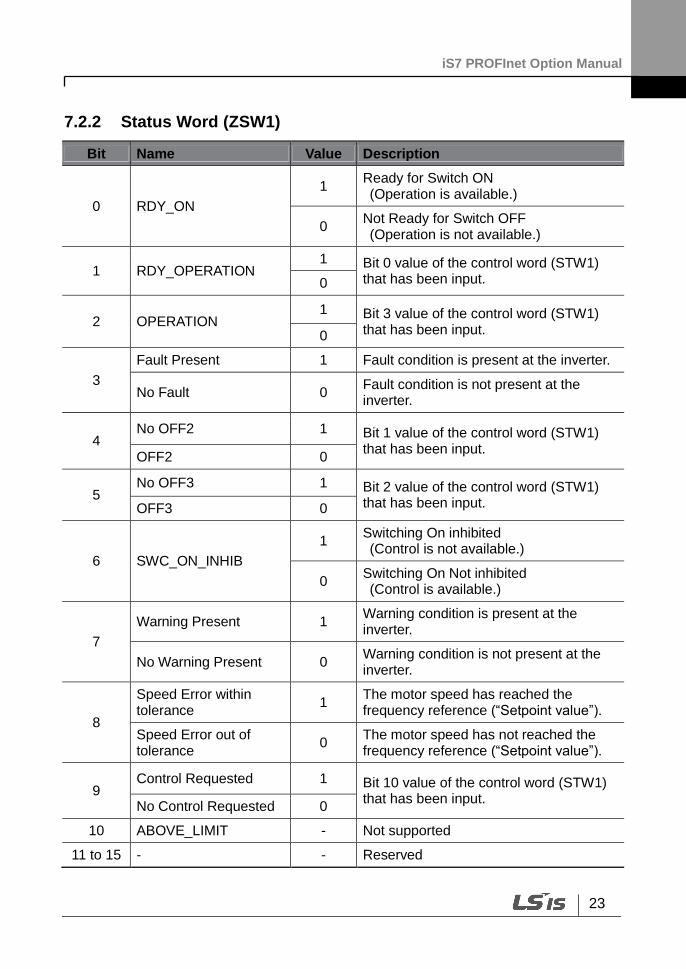
7.2.2 Status Word (ZSW1)
Bit Name Value Description
0 RDY_ON
1 Ready for Switch ON (Operation is available.)
0 Not Ready for Switch OFF (Operation is not available.)
1 RDY_OPERATION 1 Bit 0 value of the control word (STW1)
that has been input. 0
2 OPERATION 1 Bit 3 value of the control word (STW1)
that has been input. 0
3
Fault Present 1 Fault condition is present at the inverter.
No Fault 0 Fault condition is not present at the inverter.
4 No OFF2 1 Bit 1 value of the control word (STW1)
that has been input. OFF2 0
5 No OFF3 1 Bit 2 value of the control word (STW1)
that has been input. OFF3 0
6 SWC_ON_INHIB
1 Switching On inhibited (Control is not available.)
0 Switching On Not inhibited (Control is available.)
7
Warning Present 1 Warning condition is present at the inverter.
No Warning Present 0 Warning condition is not present at the inverter.
8
Speed Error within tolerance
1 The motor speed has reached the frequency reference (“Setpoint value”).
Speed Error out of tolerance
0 The motor speed has not reached the frequency reference (“Setpoint value”).
9 Control Requested 1 Bit 10 value of the control word (STW1)
that has been input. No Control Requested 0
10 ABOVE_LIMIT - Not supported
11 to 15 - - Reserved

iS7 PROFInet Option Manual
24
“bits 0 to 2” and “bit 6” indicate the following communication module status, as explained in <10. PROFIdrive Status Diagram>.
Status Word Status
xxxx xxxx x1xx x000 “Switching On Inhibited”
xxxx xxxx x0xx x001 “Ready For Switching On”
xxxx xxxx x0xx x011 “Ready For Operation”
xxxx xxxx x0xx x111 “Operation”
Note
“X” in the bit setting example indicates that the bit can be set to either 0 or 1 without affecting the control word bit settings.
7.2.3 Setpoint value
Frequency reference for inverter operation. Setpoint value is expressed in Hz, and can be increased or decreased by 0.01 Hz.
7.2.4 Actual speed value
The inverter’s actual output frequency. Actual speed value is expressed in Hz, and can be increased or decreased by 0.01 Hz.
7.2.5 Alarm Information
Bit Name Description
0 Bit for displaying “latch type trip information-1”
This bit is set to 1 when more than one bit in the “latch type trip information-1” parameter bit field is set to 1. Otherwise, it is set to 0. This bit references address 0h0330 in the inverter’s compatible parameter communication addresses.
1 Bit for displaying “latch type trip information-2”
This bit is set to 1 when more than one bit in the “latch type trip information-2” parameter bit field is set to 1. Otherwise, it is set to 0. This bit references address 0h0331 in the inverter’s

iS7 PROFInet Option Manual
25
Bit Name Description
compatible parameter communication addresses.
2 Bit for displaying “level type trip information”
This bit is set to 1 when more than one bit in the “level type trip information” parameter bit field is set to 1. Otherwise, it is set to 0. This bit references address 0h0332 in the inverter’s compatible parameter communication addresses.
3 Bit for displaying “H/W Diagnosis Trip information”
This bit is set to 1 when more than one bit in the “H/W Diagnosis Trip information” parameter bit field is set to 1. Otherwise, it is set to 0. This bit references address 0h0333 in the inverter’s compatible parameter communication addresses.
4 Bit for displaying “Warning information”
This bit is set to 1 when more than one bit in the “Warning information” parameter bit field is set to 1. Otherwise, it is set to 0. This bit references address 0h0334 in the inverter’s compatible parameter communication addresses.
5 to 15 - Reserved
7.2.6 Torque
The inverter’s output torque. Torque is expressed in percentages (%), and can be increased or decreased by 0.1%.
Torque value is displayed correctly only if the inverter’s control mode is set to “Sensorless” or “Vector.”
7.2.7 Current
The inverter’s output current. Torque is expressed in amperes (A), and can be increased or decreased by 0.1 A.
7.2.8 Dummy
Not used
iS7 PROFInet Option Manual
26
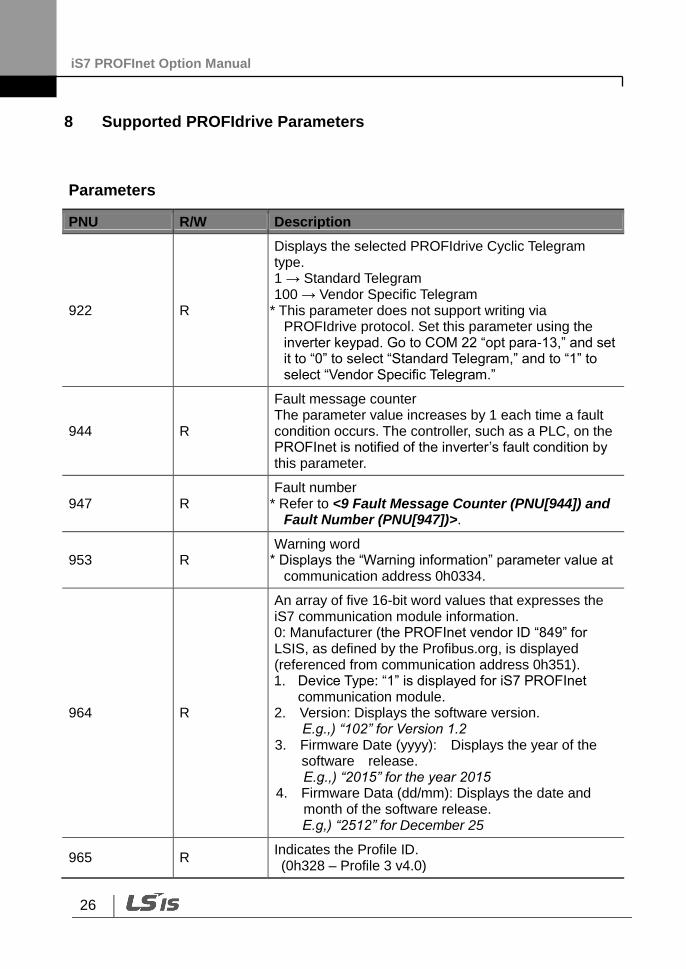
8 Supported PROFIdrive Parameters
Parameters
PNU R/W Description
922 R
Displays the selected PROFIdrive Cyclic Telegram type. 1 → Standard Telegram 100 → Vendor Specific Telegram
* This parameter does not support writing via PROFIdrive protocol. Set this parameter using the inverter keypad. Go to COM 22 “opt para-13,” and set it to “0” to select “Standard Telegram,” and to “1” to select “Vendor Specific Telegram.”
944 R
Fault message counter The parameter value increases by 1 each time a fault condition occurs. The controller, such as a PLC, on the PROFInet is notified of the inverter’s fault condition by this parameter.
947 R Fault number
* Refer to <9 Fault Message Counter (PNU[944]) and Fault Number (PNU[947])>.
953 R Warning word
* Displays the “Warning information” parameter value at communication address 0h0334.
964 R
An array of five 16-bit word values that expresses the iS7 communication module information. 0: Manufacturer (the PROFInet vendor ID “849” for LSIS, as defined by the Profibus.org, is displayed (referenced from communication address 0h351). 1. Device Type: “1” is displayed for iS7 PROFInet
communication module. 2. Version: Displays the software version.
E.g.,) “102” for Version 1.2 3. Firmware Date (yyyy): Displays the year of the
software release. E.g.,) “2015” for the year 2015
4. Firmware Data (dd/mm): Displays the date and month of the software release. E.g,) “2512” for December 25
965 R Indicates the Profile ID. (0h328 – Profile 3 v4.0)
iS7 PROFInet Option Manual
27
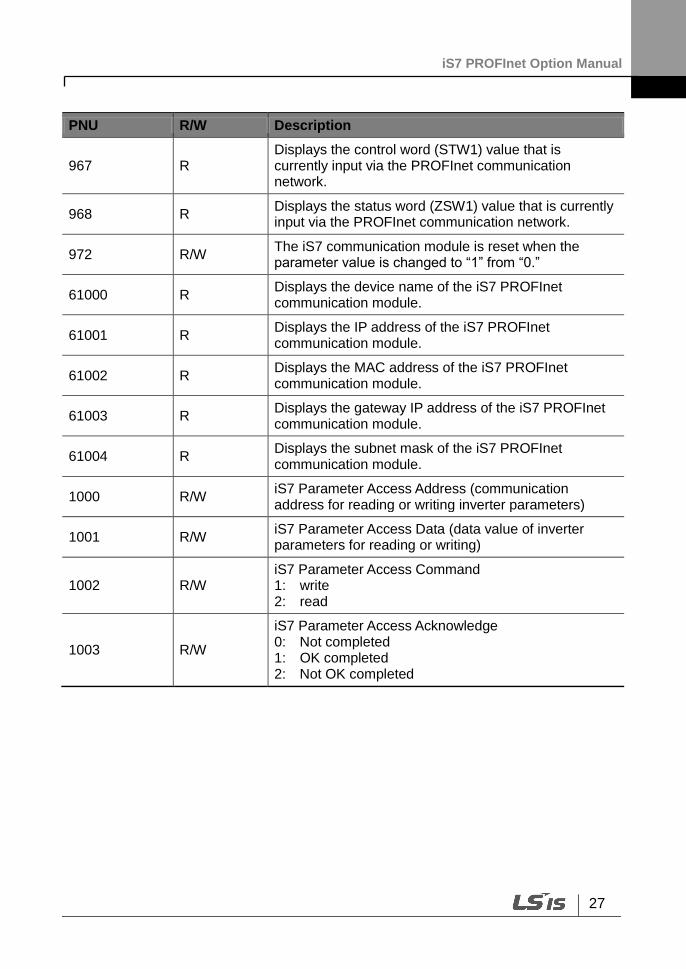
PNU R/W Description
967 R Displays the control word (STW1) value that is currently input via the PROFInet communication network.
968 R Displays the status word (ZSW1) value that is currently input via the PROFInet communication network.
972 R/W The iS7 communication module is reset when the parameter value is changed to “1” from “0.”
61000 R Displays the device name of the iS7 PROFInet communication module.
61001 R Displays the IP address of the iS7 PROFInet communication module.
61002 R Displays the MAC address of the iS7 PROFInet communication module.
61003 R Displays the gateway IP address of the iS7 PROFInet communication module.
61004 R Displays the subnet mask of the iS7 PROFInet communication module.
1000 R/W iS7 Parameter Access Address (communication address for reading or writing inverter parameters)
1001 R/W iS7 Parameter Access Data (data value of inverter parameters for reading or writing)
1002 R/W iS7 Parameter Access Command 1: write 2: read
1003 R/W
iS7 Parameter Access Acknowledge 0: Not completed 1: OK completed 2: Not OK completed
iS7 PROFInet Option Manual
28
9 Fault Message Counter (PNU[944]) and Fault Number (PNU[947])
The Fault Message Counter (PNU[944]) parameter value increases by 1 each time an inverter fault occurs, and the fault is saved at the Fault Number (PNU[947]) parameter.
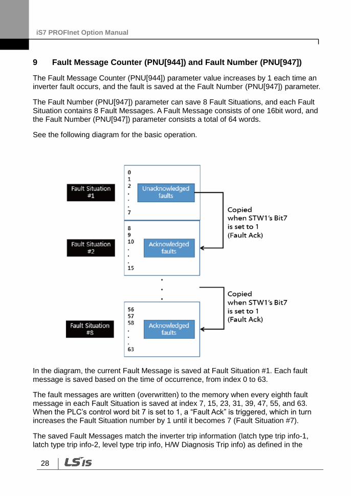
The Fault Number (PNU[947]) parameter can save 8 Fault Situations, and each Fault Situation contains 8 Fault Messages. A Fault Message consists of one 16bit word, and the Fault Number (PNU[947]) parameter consists a total of 64 words.
See the following diagram for the basic operation.
In the diagram, the current Fault Message is saved at Fault Situation #1. Each fault message is saved based on the time of occurrence, from index 0 to 63.
The fault messages are written (overwritten) to the memory when every eighth fault message in each Fault Situation is saved at index 7, 15, 23, 31, 39, 47, 55, and 63. When the PLC’s control word bit 7 is set to 1, a “Fault Ack” is triggered, which in turn increases the Fault Situation number by 1 until it becomes 7 (Fault Situation #7).
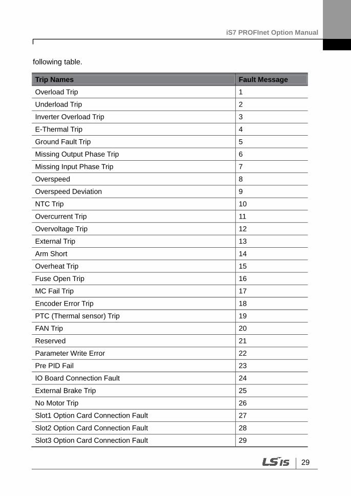
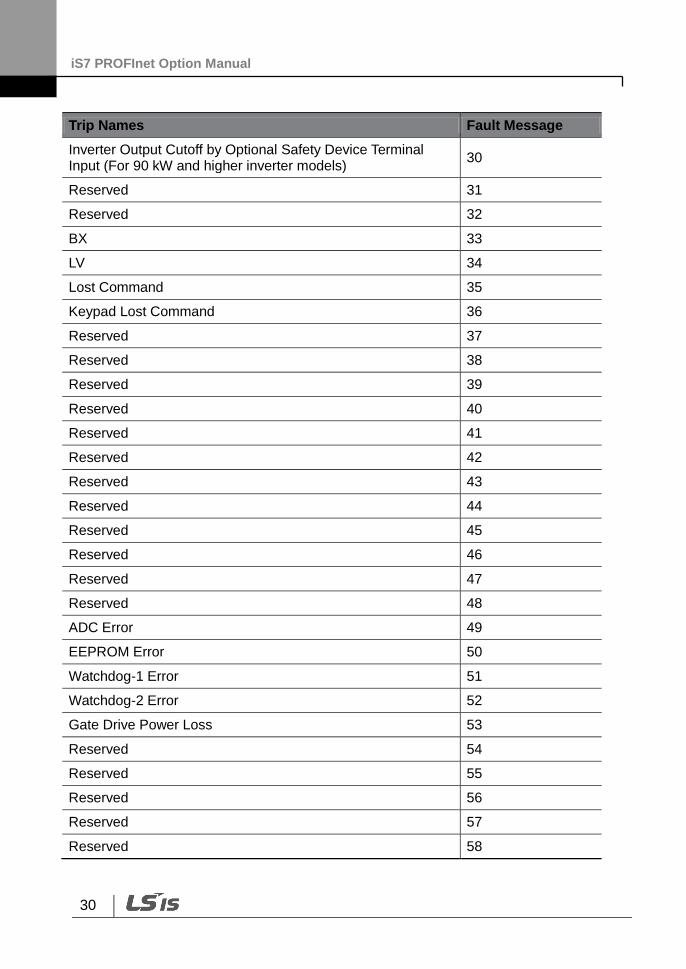
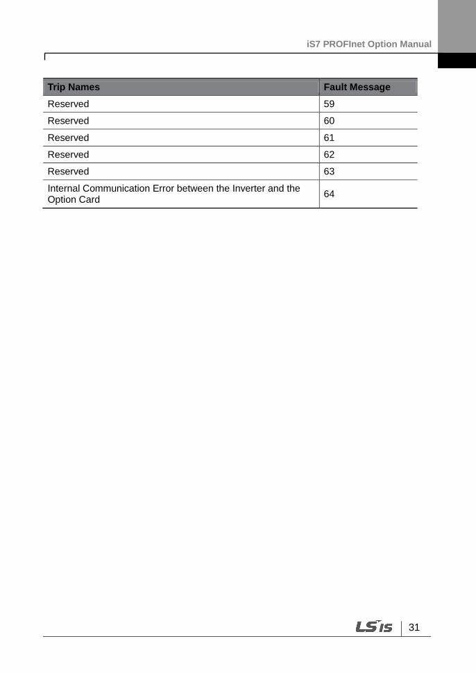
The saved Fault Messages match the inverter trip information (latch type trip info-1, latch type trip info-2, level type trip info, H/W Diagnosis Trip info) as defined in the
iS7 PROFInet Option Manual
29
following table.
Trip Names Fault Message
Overload Trip 1
Underload Trip 2
Inverter Overload Trip 3
E-Thermal Trip 4
Ground Fault Trip 5
Missing Output Phase Trip 6
Missing Input Phase Trip 7
Overspeed 8
Overspeed Deviation 9
NTC Trip 10
Overcurrent Trip 11
Overvoltage Trip 12
External Trip 13
Arm Short 14
Overheat Trip 15
Fuse Open Trip 16
MC Fail Trip 17
Encoder Error Trip 18
PTC (Thermal sensor) Trip 19
FAN Trip 20
Reserved 21
Parameter Write Error 22
Pre PID Fail 23
IO Board Connection Fault 24
External Brake Trip 25
No Motor Trip 26
Slot1 Option Card Connection Fault 27
Slot2 Option Card Connection Fault 28
Slot3 Option Card Connection Fault 29
iS7 PROFInet Option Manual
30
Trip Names Fault Message
Inverter Output Cutoff by Optional Safety Device Terminal Input (For 90 kW and higher inverter models)
30
Reserved 31
Reserved 32
BX 33
LV 34
Lost Command 35
Keypad Lost Command 36
Reserved 37
Reserved 38
Reserved 39
Reserved 40
Reserved 41
Reserved 42
Reserved 43
Reserved 44
Reserved 45
Reserved 46
Reserved 47
Reserved 48
ADC Error 49
EEPROM Error 50
Watchdog-1 Error 51
Watchdog-2 Error 52
Gate Drive Power Loss 53
Reserved 54
Reserved 55
Reserved 56
Reserved 57
Reserved 58
iS7 PROFInet Option Manual
31
Trip Names Fault Message
Reserved 59
Reserved 60
Reserved 61
Reserved 62
Reserved 63
Internal Communication Error between the Inverter and the Option Card
64
iS7 PROFInet Option Manual
32
10 Accessing the iS7 Common Parameters using the PROFIdrive Parameters
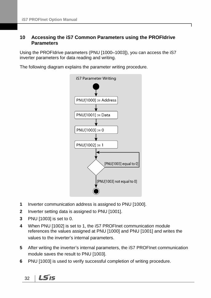
Using the PROFIdrive parameters (PNU [1000–1003]), you can access the iS7 inverter parameters for data reading and writing.
The following diagram explains the parameter writing procedure.
1 Inverter communication address is assigned to PNU [1000].
2 Inverter setting data is assigned to PNU [1001].
3 PNU [1003] is set to 0.
4 When PNU [1002] is set to 1, the iS7 PROFInet communication module references the values assigned at PNU [1000] and PNU [1001] and writes the
values to the inverter’s internal parameters.
5 After writing the inverter’s internal parameters, the iS7 PROFInet communication
module saves the result to PNU [1003].
6 PNU [1003] is used to verify successful completion of writing procedure.
iS7 PROFInet Option Manual
33
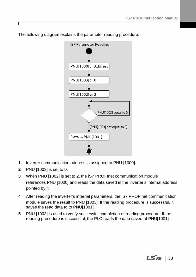
The following diagram explains the parameter reading procedure.
1 Inverter communication address is assigned to PNU [1000].
2 PNU [1003] is set to 0.
3 When PNU [1002] is set to 2, the iS7 PROFInet communication module
references PNU [1000] and reads the data saved in the inverter’s internal address
pointed by it.
4 After reading the inverter’s internal parameters, the iS7 PROFInet communication
module saves the result to PNU [1003]. If the reading procedure is successful, it saves the read data to to PNU[1001].
5 PNU [1003] is used to verify successful completion of reading procedure. If the reading procedure is successful, the PLC reads the data saved at PNU[1001].

iS7 PROFInet Option Manual
34
11 Accessing iS7 Inverter Parameters using the PROFInet Record Data Object
Using the PROFInet Record Data object, you can access the iS7 inverter parameters for data reading and writing, without the PROFIdrive communication protocol.
The inverter’s parameter data is assigned to the PROFInet Record Data from the index address 0h5000. Using the PROFInet IO RW service, you can directly access the addresses to perform reading and writing.
For example, Siemens PLC users may access the inverter’s parameter data mapped to the PROFInet Record using “WRREC” and “RDREC” function blocks. Refer to the user’s manual that that is supplied with the inverter for more information about the inverter parameter data.
E.g.) The inverter’s common parameter address 0h0001 is assigned to a PROFInet index address 0h5001.
iS7 PROFInet Option Manual
35
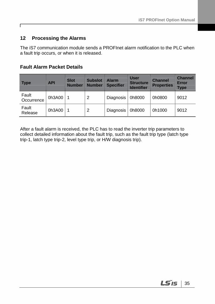
12 Processing the Alarms
The iS7 communication module sends a PROFInet alarm notification to the PLC when a fault trip occurs, or when it is released.
Fault Alarm Packet Details
Type API Slot Number
Subslot Number
Alarm Specifier
User Structure Identifier
Channel Properties
Channel Error Type
Fault Occurrence
0h3A00 1 2 Diagnosis 0h8000 0h0800 9012
Fault Release
0h3A00 1 2 Diagnosis 0h8000 0h1000 9012
After a fault alarm is received, the PLC has to read the inverter trip parameters to collect detailed information about the fault trip, such as the fault trip type (latch type trip-1, latch type trip-2, level type trip, or H/W diagnosis trip).
iS7 PROFInet Option Manual
36
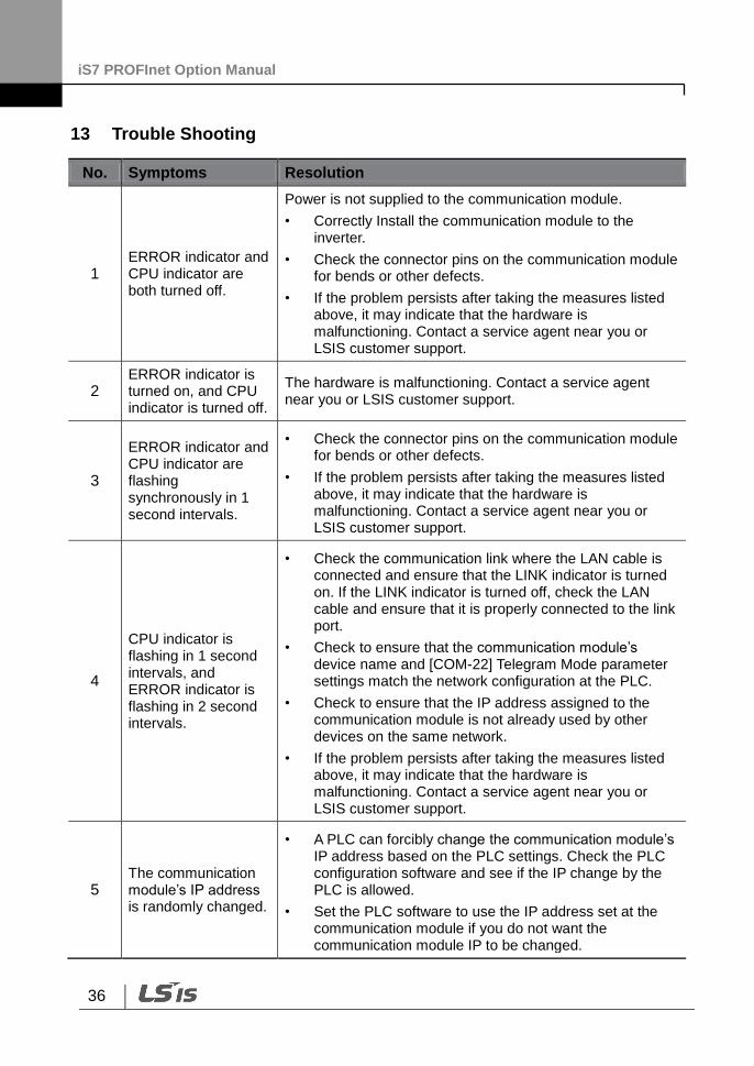
13 Trouble Shooting
No. Symptoms Resolution
1 ERROR indicator and CPU indicator are both turned off.
Power is not supplied to the communication module.
• Correctly Install the communication module to the inverter.
• Check the connector pins on the communication module for bends or other defects.
• If the problem persists after taking the measures listed above, it may indicate that the hardware is malfunctioning. Contact a service agent near you or LSIS customer support.
2 ERROR indicator is turned on, and CPU indicator is turned off.
The hardware is malfunctioning. Contact a service agent near you or LSIS customer support.
3
ERROR indicator and CPU indicator are flashing synchronously in 1 second intervals.
• Check the connector pins on the communication module for bends or other defects.
• If the problem persists after taking the measures listed above, it may indicate that the hardware is malfunctioning. Contact a service agent near you or LSIS customer support.
4
CPU indicator is flashing in 1 second intervals, and ERROR indicator is flashing in 2 second intervals.
• Check the communication link where the LAN cable is connected and ensure that the LINK indicator is turned on. If the LINK indicator is turned off, check the LAN cable and ensure that it is properly connected to the link port.
• Check to ensure that the communication module’s device name and [COM-22] Telegram Mode parameter settings match the network configuration at the PLC.
• Check to ensure that the IP address assigned to the communication module is not already used by other devices on the same network.
• If the problem persists after taking the measures listed above, it may indicate that the hardware is malfunctioning. Contact a service agent near you or LSIS customer support.
5 The communication module’s IP address is randomly changed.
• A PLC can forcibly change the communication module’s IP address based on the PLC settings. Check the PLC configuration software and see if the IP change by the PLC is allowed.
• Set the PLC software to use the IP address set at the communication module if you do not want the communication module IP to be changed.
iS7 PROFInet Option Manual
37
Maker LS Industrial Systems Co., Ltd. Installation
(Start-up) Date
Model No. SV-iS7 PROFInet Option Board Warranty Period
Customer
Information
Name
Address
Tel.
Sales Office
(Distributor)
Name
Address
Tel.
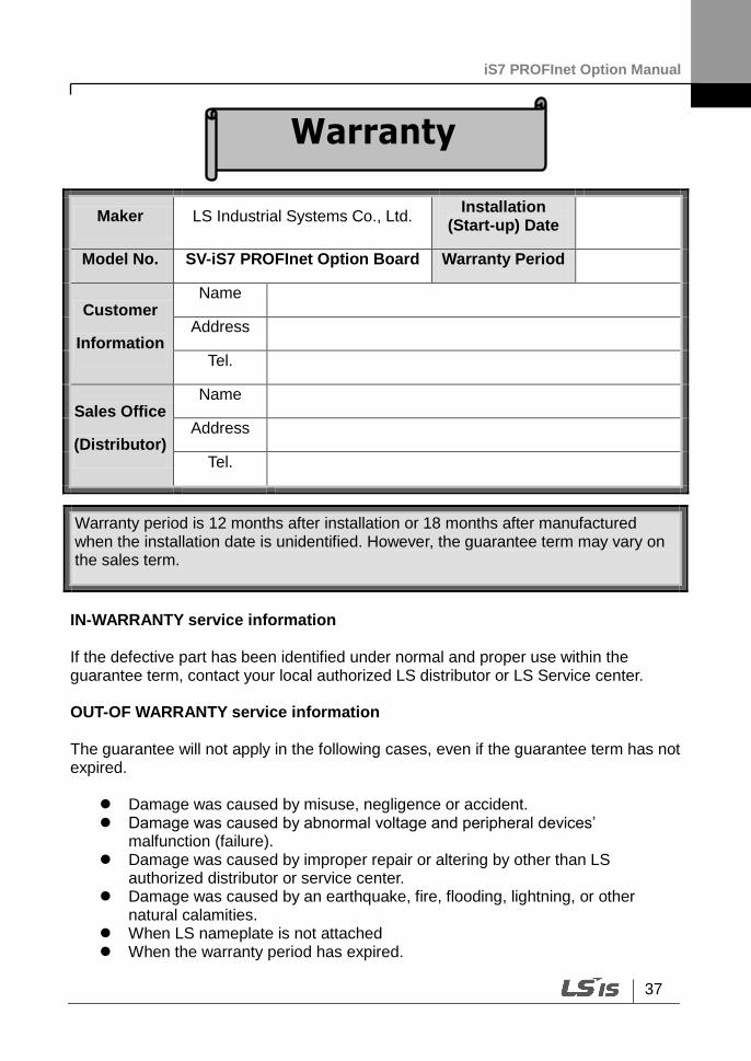
IN-WARRANTY service information If the defective part has been identified under normal and proper use within the guarantee term, contact your local authorized LS distributor or LS Service center. OUT-OF WARRANTY service information The guarantee will not apply in the following cases, even if the guarantee term has not expired.
Damage was caused by misuse, negligence or accident. Damage was caused by abnormal voltage and peripheral devices’
malfunction (failure). Damage was caused by improper repair or altering by other than LS
authorized distributor or service center. Damage was caused by an earthquake, fire, flooding, lightning, or other
natural calamities. When LS nameplate is not attached When the warranty period has expired.
Warranty period is 12 months after installation or 18 months after manufactured when the installation date is unidentified. However, the guarantee term may vary on the sales term.
iS7 PROFInet Option Manual
1
제품을 사용하기 전에
먼저 저희 iS7 PROFInet 옵션 보드를 사용하여 주셔서 감사합니다.
안전상의 주의사항
안전상의 주의사항은 사고나 위험을 사전에 예방하여 제품을 안전하고 올바르게 사용하기 위한 것
이므로 반드시 지켜주십시오.
주의사항은 ‘경고’와 ‘주의’의 두 가지로 구분되어 있으며 ‘경고’와 ‘주의’의 의미는 다음과 같습니다.
경 고
주 의
제품과 사용설명서에 표시된 그림기호의 의미는 다음과 같습니다.
는 위험이 발생할 우려가 있으므로 주의하라는 기호 입니다.
는 감전의 가능성이 있으므로 주의하라는 기호 입니다.
사용설명서를 읽고 난 후 사용하는 사람이 언제라도 볼 수 있는 장소에 보관 하십시오.
SV-iS7 시리즈 인버터의 기능을 안전하게 사용하기 위하여 이 사용 설명서를 잘 읽어 보십시오.
주 의
옵션보드의 CMOS 소자들의 취급에 주의하십시오.
정전기에 의한 고장의 원인이 됩니다.
통신 신호선 등의 변경 접속은 인버터 전원을 내린 상태에서 하십시오.
통신불량 및 고장의 원인이 됩니다.
인버터 본체와 옵션보드 커넥터가 정확히 일치하게 접속되도록 하십시오.
통신불량 및 고장의 원인이 됩니다.
파라미터를 설정할 때는 파라미터 unit 을 확인하시기 바랍니다.
통신불량의 원인이 됩니다.
지시사항을 위반할 때 심각한 상해나 사망이 발생할 가능성이 있는
경우
지시사항을 위반할 때 경미한 상해나 제품손상이 발생할 가능성이
있는 경우
iS7 PROFInet Option Manual
2
목 차
1. 소개 ................................................................................................................................................................................................... 4
2. PROFInet Technical Features ................................................................................................................................................. 4
3. 제품 구성물 ................................................................................................................................................................................... 4
4. iS7 PROFInet 통신 옵션 형명 ............................................................................................................................................... 5
5. PROFInet 통신 옵션 외관 및 설치 .................................................................................................................................... 5
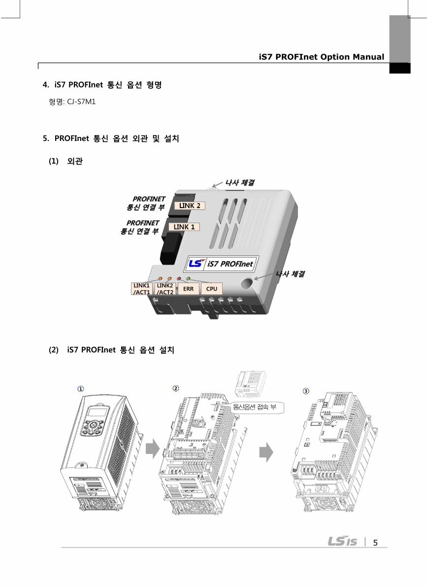
(1) 외관 ............................................................................................................................................................................................ 5
(2) iS7 PROFInet 통신 옵션 설치 ....................................................................................................................................... 5
(3) PROFInet 통신 옵션 LED 표시 부 .............................................................................................................................. 6
(4) 외부 24V 전원 입력 부.................................................................................................................................................... 8
6. Network 연결 ............................................................................................................................................................................. 10
(1) 통신선 연결 단자 관련 정보 ....................................................................................................................................... 10
(2) 통신선 연결 단자 부 ....................................................................................................................................................... 10
7. Network 케이블 규격 ............................................................................................................................................................. 11
8. PROFInet 통신 옵션과 관련 Keypad 파라미터 .......................................................................................................... 11
9. PROFInet 통신 옵션과 관련 Keypad 파라미터 설명 .............................................................................................. 13
iS7 PROFInet Option Manual
3
(1) CNF 그룹 ............................................................................................................................................................................... 13
(2) DRV 그룹 .............................................................................................................................................................................. 13
(3) COM 그룹 ............................................................................................................................................................................. 13
(4) PRT 그룹 ............................................................................................................................................................................... 15
10. PROFIdrive 상태도 ................................................................................................................................................................ 16
11. 지원 PROFIdrive Cyclic Telegram .................................................................................................................................. 19
(1) Standard Telegram (Mode : 0) .................................................................................................................................... 19
(2) Vender Specific Telegram (Mode : 1) ...................................................................................................................... 19
12. 지원 PROFIdrive 파라미터 ................................................................................................................................................ 26
13. PNU[944] Fault Message Counter 와 PNU[947] Fault Number 설명 ............................................................ 29
14. PROFIdrive 파라미터를 이용한 iS7 공통 파라미터 접근 절차 ....................................................................... 33
15. PROFInet Record Data Object 를 이용한 iS7 Parameter Access ..................................................................... 37
16. Alarm 처리 ............................................................................................................................................................................... 37
17. GSDML 파일 ............................................................................................................................................................................ 37
18. 이상 대책 및 점검 (Trouble Shooting) ....................................................................................................................... 37

iS7 PROFInet Option Manual
4
1. 소개
PROFInet 통신 옵션 카드는 SV-iS7 인버터를 산업통신망 국제규격인 IEC 61158의 Type 10에
해당하는 PROFInet 네트워크에 연결되도록 합니다.
Full-duplex 방식을 이용하여 충돌 없는 통신으로 통신상의 실시간성을 확보하며, iS7 인버터의 제어
및 모니터링이 PLC의 시퀀스 프로그램 또는 임의의 Master Module에 의해 제어가 가능해집니다.
배선이 간단하여 설치 시간을 절감할 수 있고 유지 보수가 쉬워집니다.
2. PROFInet Technical Features
항목 설명
통신 프로토콜 PROFInet IO CC-A
통신 속도 100Mbps
통신 방식 Full Duplex
최대 접속 국수 64 대
거리 100m (Twisted Pair)
Service PROFIdrive Class 1
Topology Line, Tree, Star topology
3. 제품 구성물
PROFInet 통신 옵션 카드 1개, 체결 나사 2개, PROFInet 통신 옵션 매뉴얼로 구성되어 있습니다.
PROFInet 통신 옵션 카드 체결 나사 PROFInet 통신옵션 매뉴얼
iS7 PROFInet Option Manual
5
4. iS7 PROFInet 통신 옵션 형명
형명: CJ-S7M1
5. PROFInet 통신 옵션 외관 및 설치
(1) 외관
(2) iS7 PROFInet 통신 옵션 설치
iS7 PROFInet Option Manual
6
① iS7 인버터 본체의 Cover를 분리합니다.
② iS7 통신옵션 접속 부에 PROFInet 통신 옵션을 체결한 후, 나사 체결(2개)을 해주십시오.
③ iS7 인버터와 PROFInet 통신 옵션이 체결되었습니다.
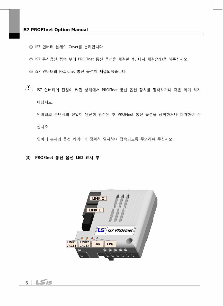
iS7 인버터의 전원이 켜진 상태에서 PROFInet 통신 옵션 장치를 장착하거나 혹은 제거 하지
마십시오.
인버터의 콘덴서의 전압이 완전히 방전된 후 PROFInet 통신 옵션을 장착하거나 제거하여 주
십시오.
인버터 본체와 옵션 커넥터가 정확히 일치하여 접속되도록 주의하여 주십시오.
(3) PROFInet 통신 옵션 LED 표시 부
iS7 PROFInet Option Manual
7
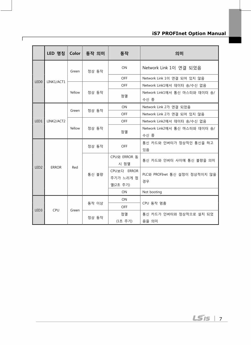
LED 명칭 Color 동작 의미 동작 의미
LED0 LINK1/ACT1
Green 정상 동작 ON Network Link 1이 연결 되었음
OFF Network Link 1이 연결 되어 있지 않음
Yellow 정상 동작
OFF Network Link1에서 데이터 송/수신 없음
점멸 Network Link1에서 통신 마스터와 데이터 송/
수신 중
LED1 LINK2/ACT2
Green 정상 동작 ON Network Link 2가 연결 되었음
OFF Network Link 2가 연결 되어 있지 않음
Yellow 정상 동작
OFF Network Link2에서 데이터 송/수신 없음
점멸 Network Link2에서 통신 마스터와 데이터 송/
수신 중
LED2 ERROR Red
정상 동작 OFF 통신 카드와 인버터가 정상적인 통신을 하고
있음
통신 불량
CPU와 ERROR 동
시 점멸 통신 카드와 인버터 사이에 통신 불량을 의미
CPU보다 ERROR
주기가 느리게 점
멸(2초 주기)
PLC와 PROFInet 통신 설정이 정상적이지 않을
경우
ON Not booting
LED3 CPU Green
동작 이상 ON
CPU 동작 멈춤 OFF
정상 동작 점멸
(1초 주기)
통신 카드가 인버터와 정상적으로 설치 되었
음을 의미
iS7 PROFInet Option Manual
8
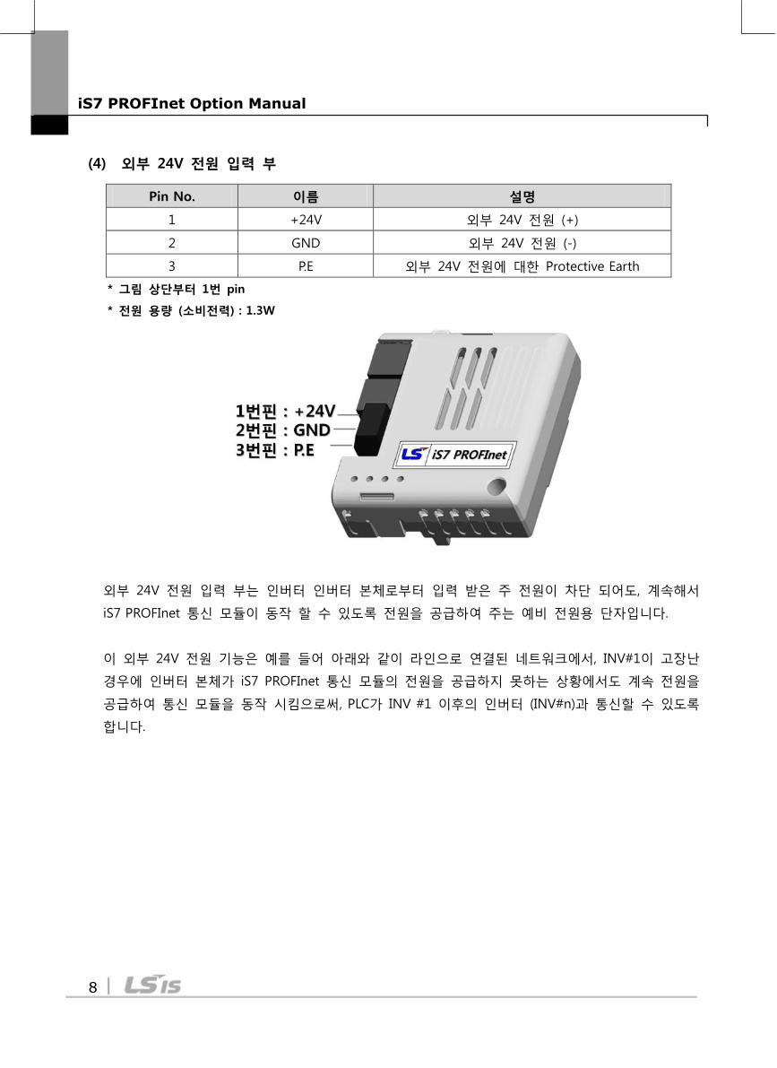
(4) 외부 24V 전원 입력 부
Pin No. 이름 설명
1 +24V 외부 24V 전원 (+)
2 GND 외부 24V 전원 (-)
3 P.E 외부 24V 전원에 대한 Protective Earth
* 그림 상단부터 1번 pin
* 전원 용량 (소비전력) : 1.3W
외부 24V 전원 입력 부는 인버터 인버터 본체로부터 입력 받은 주 전원이 차단 되어도, 계속해서
iS7 PROFInet 통신 모듈이 동작 할 수 있도록 전원을 공급하여 주는 예비 전원용 단자입니다.
이 외부 24V 전원 기능은 예를 들어 아래와 같이 라인으로 연결된 네트워크에서, INV#1이 고장난
경우에 인버터 본체가 iS7 PROFInet 통신 모듈의 전원을 공급하지 못하는 상황에서도 계속 전원을
공급하여 통신 모듈을 동작 시킴으로써, PLC가 INV #1 이후의 인버터 (INV#n)과 통신할 수 있도록
합니다.
iS7 PROFInet Option Manual
9
iS7 PROFInet Option Manual
10
외부 24V 전원이 공급되는 상태에서 인버터 본체 전원이 차단될 경우, iS7 PROFInet 통신 모듈은
“Fault 발생 Alarm”를 PLC에 전송합니다. Alarm 수신 후 PLC 측에서 “H/W Diagnosis Trip
정보(통신 주소: 0h0333)”의 최상위 Bit가 1로 설정된 것을 확인할 수 있습니다.
주의 : 외부 24V 전원의 오차 범위는 –15~+20% 입니다. 전원 연결 시 용량에 맞게 사용하여 주십시오.
주의 : 외부 24V는 통신모듈의 전원만 공급합니다. 따라서 인버터 본체 전원이 차단된 상태이므로
로더 및 인버터 본체가 동작하지 않습니다.
6. Network 연결
(1) 통신선 연결 단자 관련 정보
Pin No. 신호 설명 선 색
1 TX+ 송신 데이터 Plus 흰/황색
2 TX- 송신 데이터 Minus 황색
3 RX+ 수신 데이터 Plus 흰/녹색
4 NONE 사용 안 함 청색
5 NONE 사용 안 함 흰/청색
6 RX- 수신 데이터 Minus 녹색
7 NONE 사용 안 함 흰/갈색
8 NONE 사용 안 함 갈색
(2) 통신선 연결 단자 부
** 1번과 2번 핀에 연결된 선은 반드시 서로 꼬여 있어야 합니다.
** 3번과 6번 핀에 연결된 선도 반드시 서로 꼬여 있어야 합니다.
1
8
1
2
3
4
5
6
7
8
iS7 PROFInet Option Manual
11
7. Network 케이블 규격
PROFInet 통신 옵션을 사용하기 위해서는 STP(일반적으로 카테고리 6a 이상)의 케이블을 사용
합니다.
8. PROFInet 통신 옵션과 관련 Keypad 파라미터
PROFInet 통신 옵션을 사용하여 iS7 인버터를 운전 시키고 싶은 경우에는 Keypad의 DRV-06 Cmd
Source를 [4 Fieldbus]로 설정하여 주십시오.
또한, PROFInet 통신 옵션을 사용하여 인버터 주파수 지령을 내리고 싶은 경우에는 DRV-07 Freq Ref
Src를 [8 Fieldbus]로 설정하여 주십시오.
Code 파라미터 이름 초기값 Range
CNF 30 Option-1 Type -
iS7 PROFInet 카드를 장착하면 PROFInet 으로 통신
옵션을 자동으로 인식하여 표시합니다.주1)
DRV
06 Cmd Source 1 Fx/Rx-1
0 Keypad
1 Fx/Rx-1
2 Fx/Rx-2
3 Int 485
4 Fieldbus
07 Freq Ref Src 0 Keypad-1
0 Keypad-1
1 Keypad-2
2 V1
3 I1
4 V2
5 I2
6 Int 485
7 Encoder
8 FieldBus
9 PLC
COM
06 FBus S/W Ver - -
09 FBus Led - -
10 opt para-1 0 IP - 1
11 opt para-2 0 IP – 2

iS7 PROFInet Option Manual
12
주 1)(인버터 S/W 버전이 1.14 이하인 경우 PROFInet 아닌 다른 이름으로 표시될 수 있습니다)
12 opt para-3 0 IP – 3
13 opt para-4 0 IP - 4
14 opt para-5 0 Subnet Mask - 1
15 opt para-6 0 Subnet Mask - 2
16 opt para-7 0 Subnet Mask – 3
17 opt para-8 0 Subnet Mask - 4
18 opt para-9 0 Gateway - 1
19 opt para-10 0 Gateway - 2
20 opt para-11 0 Gateway - 3
21 opt para-12 0 Gateway - 4
22 opt para-13 0 Mode(0:STD Telegram1, 1: Vender Specific Telegram)
PRT
12 Lost Cmd Source 0 None
0 None
1 Free-Run
2 Dec
3 Hold Input
4 Hold Output
5 Lost Preset
13 Lost Cmd Time 1.0 0.1 ~ 120 [s]
14 Lost Preset F 0.00 0.50 ~ 60.00 [Hz]
iS7 PROFInet Option Manual
13
9. PROFInet 통신 옵션과 관련 Keypad 파라미터 설명
(1) CNF 그룹
① [CNF-30] Option-1 Type: 옵션 슬롯1의 종류 표시
현재 iS7에 장착된 통신 카드 종류를 자동으로 나타냅니다. iS7 PROFInet 통신 옵션 카드를 iS7
인버터에 장착 시 자동으로 “Profinet”으로 표시 됩니다.
(2) DRV 그룹
① [DRV-06] Cmd Source: 운전 지령 방법
iS7 인버터의 운전 지령을 선택할 수 있습니다. PROFInet 통신 옵션을 사용하여 통신으로
운전지령을 입력하고 싶은 경우에 [4 FieldBus]를 선택하여 주십시오.
② [DRV-07] Freq Ref Src: 주파수 설정
iS7 인버터의 주파수 지령을 선택할 수 있습니다. PROFInet 통신 옵션을 사용하여 통신으로
주파수 지령을 입력하고 싶은 경우에 [8 Field Bus]를 선택하여 주십시오.
(3) COM 그룹
① [COM-06] FBus S/W Ver: 통신 옵션 S/W 버전
현재 iS7에 장착된 통신 카드의 버전이 무엇인지 자동으로 나타냅니다.
② [COM-09] FBus Led: 통신 옵션 LED 정보
iS7 PROFInet 통신 옵션의 LED 표시 부를 Keypad를 통하여 확인 할 수 있습니다. LED 표시
부에 따른 동작은 “5장 (3) PROFInet 통신 옵션 LED 표시 부”를 참고하여 주십시오.
iS7 PROFInet Option Manual
14
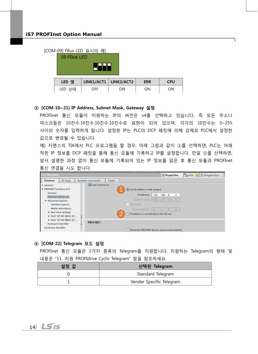
[COM-09] FBus LED 표시의 예)
09 FBus LED
③ [COM-10~21] IP Address, Subnet Mask, Gateway 설정
PROFInet 통신 모듈이 지원하는 IP의 버전은 v4를 선택하고 있습니다. 즉 모든 주소나
마스크들은 10진수.10진수.10진수.10진수로 표현이 되어 있으며, 각각의 10진수는 0~255
사이의 숫자를 입력하게 됩니다. 설정된 IP는 PLC의 DCP 패킷에 의해 강제로 PLC에서 설정한
값으로 변경될 수 있습니다.
예) 지멘스의 TIA에서 PLC 프로그램을 할 경우, 아래 그림과 같이 ①를 선택하면, PLC는 아래
적힌 IP 정보를 DCP 패킷을 통해 통신 모듈에 기록하고 IP를 설정합니다. 만일 ②를 선택하면,
앞서 설명한 과정 없이 통신 모듈에 기록되어 있는 IP 정보를 읽은 후 통신 모듈과 PROFInet
통신 연결을 시도 합니다.
④ [COM-22] Telegram 모드 설정
PROFInet 통신 모듈은 2가지 종류의 Telegram를 지원합니다. 지원하는 Telegram의 형태 및
내용은 “11. 지원 PROFIdrive Cyclic Telegram” 항을 참조하세요.
설정 값 선택된 Telegram
0 Standard Telegram
1 Vender Specific Telegram
LED 명 LINK1/ACT1 LINK2/ACT2 ERR CPU
LED 상태 OFF ON ON ON
iS7 PROFInet Option Manual
15
(4) PRT 그룹
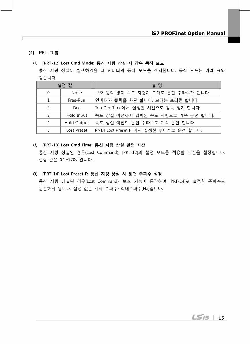
① [PRT-12] Lost Cmd Mode: 통신 지령 상실 시 감속 동작 모드
통신 지령 상실이 발생하였을 때 인버터의 동작 모드를 선택합니다. 동작 모드는 아래 표와
같습니다.
설정 값 설 명
0 None 보호 동작 없이 속도 지령이 그대로 운전 주파수가 됩니다.
1 Free-Run 인버터가 출력을 차단 합니다. 모터는 프리런 합니다.
2 Dec Trip Dec Time에서 설정한 시간으로 감속 정지 합니다.
3 Hold Input 속도 상실 이전까지 입력된 속도 지령으로 계속 운전 합니다.
4 Hold Output 속도 상실 이전의 운전 주파수로 계속 운전 합니다.
5 Lost Preset Pr-14 Lost Preset F 에서 설정한 주파수로 운전 합니다.
② [PRT-13] Lost Cmd Time: 통신 지령 상실 판정 시간
통신 지령 상실된 경우(Lost Command), [PRT-12]의 설정 모드를 적용할 시간을 설정합니다.
설정 값은 0.1~120s 입니다.
③ [PRT-14] Lost Preset F: 통신 지령 상실 시 운전 주파수 설정
통신 지령 상실된 경우(Lost Command), 보호 기능이 동작하여 [PRT-14]로 설정한 주파수로
운전하게 됩니다. 설정 값은 시작 주파수~최대주파수[Hz]입니다.
iS7 PROFInet Option Manual
16
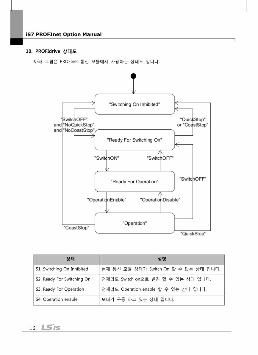
10. PROFIdrive 상태도
아래 그림은 PROFInet 통신 모듈에서 사용하는 상태도 입니다.
상태 설명
S1: Switching On Inhibited 현재 통신 모듈 상태가 Switch On 할 수 없는 상태 입니다.
S2: Ready For Switching On 언제라도 Switch on으로 변경 할 수 있는 상태 입니다.
S3: Ready For Operation 언제라도 Operation enable 할 수 있는 상태 입니다.
S4: Operation enable 모터가 구동 하고 있는 상태 입니다.
iS7 PROFInet Option Manual
17
각 상태의 천이는 PLC에서 주기적으로 내려 오는 명령에 의해 발생 합니다. 명령의 종류는 아래와
같으며 자세한 내용은 “11. 지원 PROFIdrive Cyclic Telegram” 항의 Control word 항에서 설명 합니
다.
① NoQuickStop 명령
② NoCoastStop 명령
③ SwitchOFF 명령
④ SwitchON 명령
⑤ OperationEnable 명령
⑥ OperationDisable 명령
⑦ QuickStop 명령
⑧ CoastStop 명령
iS7 PROFInet Option Manual
18
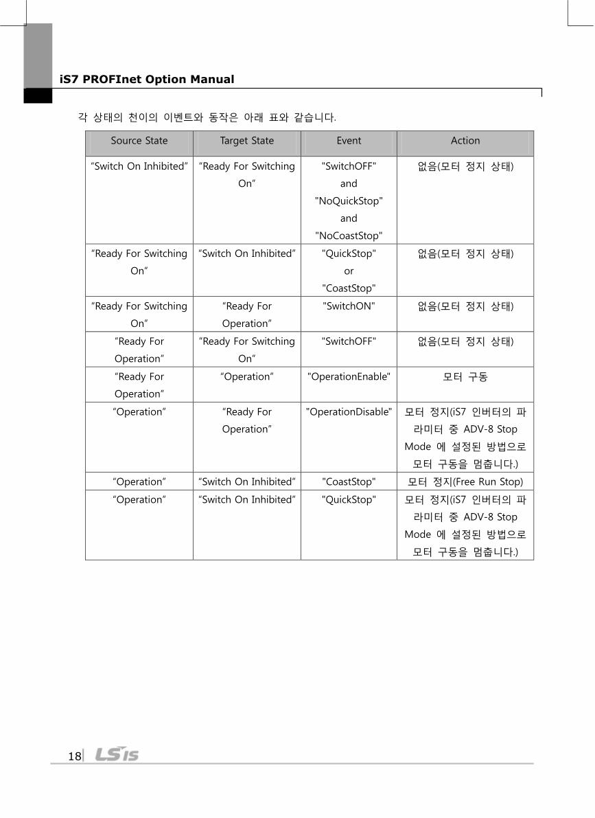
각 상태의 천이의 이벤트와 동작은 아래 표와 같습니다.
Source State Target State Event Action
“Switch On Inhibited” “Ready For Switching
On”
"SwitchOFF"
and
"NoQuickStop"
and
"NoCoastStop"
없음(모터 정지 상태)
“Ready For Switching
On”
“Switch On Inhibited” "QuickStop"
or
"CoastStop"
없음(모터 정지 상태)
“Ready For Switching
On”
“Ready For
Operation”
"SwitchON" 없음(모터 정지 상태)
“Ready For
Operation”
“Ready For Switching
On”
"SwitchOFF" 없음(모터 정지 상태)
“Ready For
Operation”
“Operation” "OperationEnable" 모터 구동
“Operation” “Ready For
Operation”
"OperationDisable" 모터 정지(iS7 인버터의 파
라미터 중 ADV-8 Stop
Mode 에 설정된 방법으로
모터 구동을 멈춥니다.)
“Operation” “Switch On Inhibited” "CoastStop" 모터 정지(Free Run Stop)
“Operation” “Switch On Inhibited” "QuickStop" 모터 정지(iS7 인버터의 파
라미터 중 ADV-8 Stop
Mode 에 설정된 방법으로
모터 구동을 멈춥니다.)
iS7 PROFInet Option Manual
19
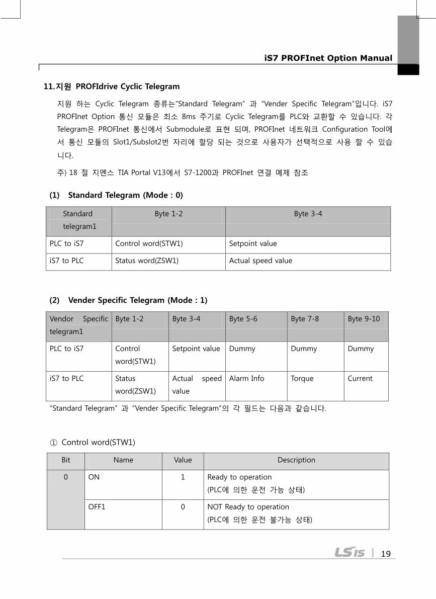
11. 지원 PROFIdrive Cyclic Telegram
지원 하는 Cyclic Telegram 종류는”Standard Telegram” 과 “Vender Specific Telegram”입니다. iS7
PROFInet Option 통신 모듈은 최소 8ms 주기로 Cyclic Telegram를 PLC와 교환할 수 있습니다. 각
Telegram은 PROFInet 통신에서 Submodule로 표현 되며, PROFInet 네트워크 Configuration Tool에
서 통신 모듈의 Slot1/Subslot2번 자리에 할당 되는 것으로 사용자가 선택적으로 사용 할 수 있습
니다.
주) 18 절 지멘스 TIA Portal V13에서 S7-1200과 PROFInet 연결 예제 참조
(1) Standard Telegram (Mode : 0)
Standard
telegram1
Byte 1-2 Byte 3-4
PLC to iS7 Control word(STW1) Setpoint value
iS7 to PLC Status word(ZSW1) Actual speed value
(2) Vender Specific Telegram (Mode : 1)
Vendor Specific
telegram1
Byte 1-2 Byte 3-4 Byte 5-6 Byte 7-8 Byte 9-10
PLC to iS7 Control
word(STW1)
Setpoint value Dummy Dummy Dummy
iS7 to PLC Status
word(ZSW1)
Actual speed
value
Alarm Info Torque Current
“Standard Telegram” 과 “Vender Specific Telegram”의 각 필드는 다음과 같습니다.
① Control word(STW1)
Bit Name Value Description
0 ON 1 Ready to operation
(PLC에 의한 운전 가능 상태)
OFF1 0 NOT Ready to operation
(PLC에 의한 운전 불가능 상태)
iS7 PROFInet Option Manual
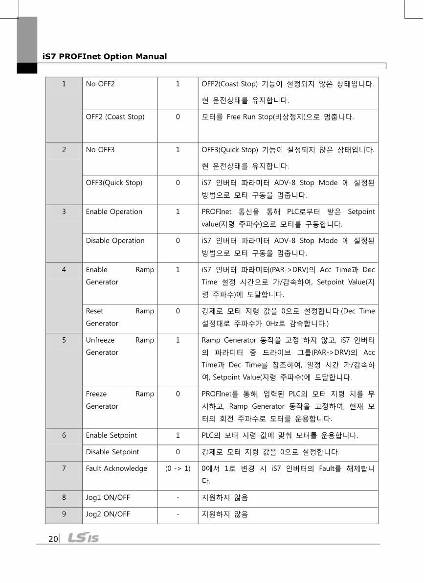
20
1 No OFF2 1 OFF2(Coast Stop) 기능이 설정되지 않은 상태입니다.
현 운전상태를 유지합니다.
OFF2 (Coast Stop)
0 모터를 Free Run Stop(비상정지)으로 멈춥니다.
2 No OFF3 1 OFF3(Quick Stop) 기능이 설정되지 않은 상태입니다.
현 운전상태를 유지합니다.
OFF3(Quick Stop) 0 iS7 인버터 파라미터 ADV-8 Stop Mode 에 설정된
방법으로 모터 구동을 멈춥니다.
3 Enable Operation 1 PROFInet 통신을 통해 PLC로부터 받은 Setpoint
value(지령 주파수)으로 모터를 구동합니다.
Disable Operation 0 iS7 인버터 파라미터 ADV-8 Stop Mode 에 설정된
방법으로 모터 구동을 멈춥니다.
4 Enable Ramp
Generator
1 iS7 인버터 파라미터(PAR->DRV)의 Acc Time과 Dec
Time 설정 시간으로 가/감속하여, Setpoint Value(지
령 주파수)에 도달합니다.
Reset Ramp
Generator
0 강제로 모터 지령 값을 0으로 설정합니다.(Dec Time
설정대로 주파수가 0Hz로 감속합니다.)
5 Unfreeze Ramp
Generator
1 Ramp Generator 동작을 고정 하지 않고, iS7 인버터
의 파라미터 중 드라이브 그룹(PAR->DRV)의 Acc
Time과 Dec Time를 참조하여, 일정 시간 가/감속하
여, Setpoint Value(지령 주파수)에 도달합니다.
Freeze Ramp
Generator
0 PROFInet를 통해, 입력된 PLC의 모터 지령 치를 무
시하고, Ramp Generator 동작을 고정하여, 현재 모
터의 회전 주파수로 모터를 운용합니다.
6 Enable Setpoint 1 PLC의 모터 지령 값에 맞춰 모터를 운용합니다.
Disable Setpoint 0 강제로 모터 지령 값을 0으로 설정합니다.
7 Fault Acknowledge (0 -> 1) 0에서 1로 변경 시 iS7 인버터의 Fault를 해제합니
다.
8 Jog1 ON/OFF - 지원하지 않음
9 Jog2 ON/OFF - 지원하지 않음
iS7 PROFInet Option Manual
21
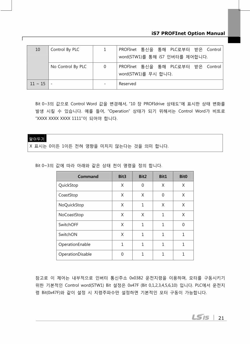
10 Control By PLC 1 PROFInet 통신을 통해 PLC로부터 받은 Control
word(STW1)를 통해 iS7 인버터를 제어합니다.
No Control By PLC 0 PROFInet 통신을 통해 PLC로부터 받은 Control
word(STW1)를 무시 합니다.
11 ~ 15 - - Reserved
Bit 0~3의 값으로 Control Word 값을 변경해서, “10 장 PROFIdrive 상태도”에 표시한 상태 변화를
발생 시킬 수 있습니다. 예를 들어, “Operation” 상태가 되기 위해서는 Control Word가 비트로
“XXXX XXXX XXXX 1111”이 되어야 합니다.
Bit 0~3의 값에 따라 아래와 같은 상태 천이 명령을 정의 합니다.
Command Bit3 Bit2 Bit1 Bit0
QuickStop X 0 X X
CoastStop X X 0 X
NoQuickStop X 1 X X
NoCoastStop X X 1 X
SwitchOFF X 1 1 0
SwitchON X 1 1 1
OperationEnable 1 1 1 1
OperationDisable 0 1 1 1
참고로 이 제어는 내부적으로 인버터 통신주소 0x0382 운전지령을 이용하며, 모터를 구동시키기
위한 기본적인 Control word(STW1) Bit 설정은 0x47F (Bit 0,1,2,3,4,5,6,10) 입니다. PLC에서 운전지
령 Bit(0x47F)와 같이 설정 시 지령주파수만 설정하면 기본적인 모터 구동이 가능합니다.
알아두기
X 표시는 0이든 1이든 전혀 영향을 미치지 않는다는 것을 의미 합니다.
iS7 PROFInet Option Manual
22
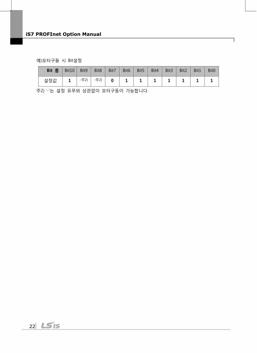
예)모터구동 시 Bit설정
Bit 종 Bit10 Bit9 Bit8 Bit7 Bit6 Bit5 Bit4 Bit3 Bit2 Bit1 Bit0
설정값 1 -주2) -주2) 0 1 1 1 1 1 1 1
주2) ’-‘는 설정 유무와 상관없이 모터구동이 가능합니다.
iS7 PROFInet Option Manual
23
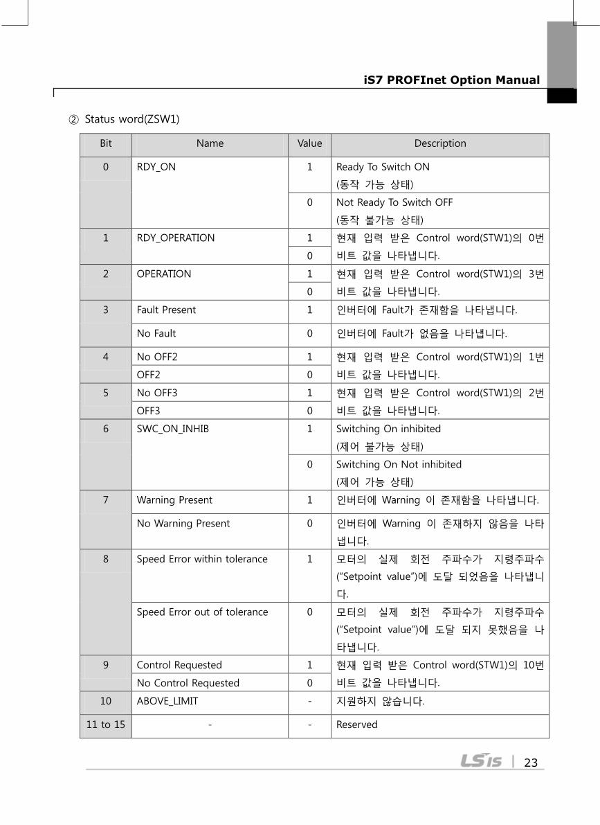
② Status word(ZSW1)
Bit Name Value Description
0 RDY_ON 1 Ready To Switch ON
(동작 가능 상태)
0 Not Ready To Switch OFF
(동작 불가능 상태)
1 RDY_OPERATION 1 현재 입력 받은 Control word(STW1)의 0번
비트 값을 나타냅니다. 0
2 OPERATION 1 현재 입력 받은 Control word(STW1)의 3번
비트 값을 나타냅니다. 0
3 Fault Present 1 인버터에 Fault가 존재함을 나타냅니다.
No Fault 0 인버터에 Fault가 없음을 나타냅니다.
4 No OFF2 1 현재 입력 받은 Control word(STW1)의 1번
비트 값을 나타냅니다. OFF2 0
5 No OFF3 1 현재 입력 받은 Control word(STW1)의 2번
비트 값을 나타냅니다. OFF3 0
6 SWC_ON_INHIB 1 Switching On inhibited
(제어 불가능 상태)
0 Switching On Not inhibited
(제어 가능 상태)
7 Warning Present 1 인버터에 Warning 이 존재함을 나타냅니다.
No Warning Present 0 인버터에 Warning 이 존재하지 않음을 나타
냅니다.
8 Speed Error within tolerance 1 모터의 실제 회전 주파수가 지령주파수
(“Setpoint value”)에 도달 되었음을 나타냅니
다.
Speed Error out of tolerance 0 모터의 실제 회전 주파수가 지령주파수
(“Setpoint value”)에 도달 되지 못했음을 나
타냅니다.
9 Control Requested 1 현재 입력 받은 Control word(STW1)의 10번
비트 값을 나타냅니다. No Control Requested 0
10 ABOVE_LIMIT - 지원하지 않습니다.
11 to 15 - - Reserved
iS7 PROFInet Option Manual
24
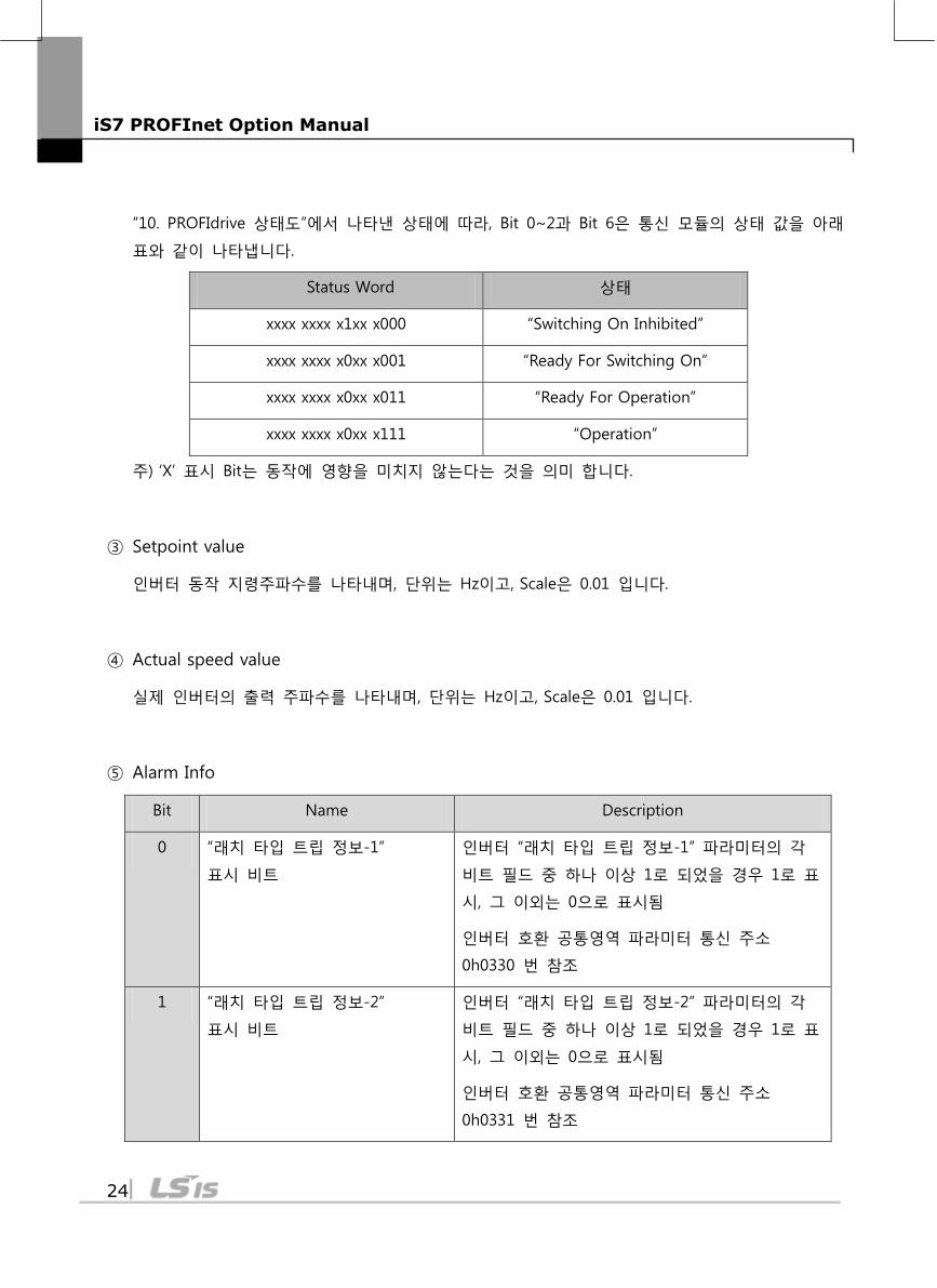
“10. PROFIdrive 상태도”에서 나타낸 상태에 따라, Bit 0~2과 Bit 6은 통신 모듈의 상태 값을 아래
표와 같이 나타냅니다.
Status Word 상태
xxxx xxxx x1xx x000 “Switching On Inhibited”
xxxx xxxx x0xx x001 “Ready For Switching On”
xxxx xxxx x0xx x011 “Ready For Operation”
xxxx xxxx x0xx x111 “Operation”
주) ‘X’ 표시 Bit는 동작에 영향을 미치지 않는다는 것을 의미 합니다.
③ Setpoint value
인버터 동작 지령주파수를 나타내며, 단위는 Hz이고, Scale은 0.01 입니다.
④ Actual speed value
실제 인버터의 출력 주파수를 나타내며, 단위는 Hz이고, Scale은 0.01 입니다.
⑤ Alarm Info
Bit Name Description
0 “래치 타입 트립 정보-1”
표시 비트
인버터 “래치 타입 트립 정보-1” 파라미터의 각
비트 필드 중 하나 이상 1로 되었을 경우 1로 표
시, 그 이외는 0으로 표시됨
인버터 호환 공통영역 파라미터 통신 주소
0h0330 번 참조
1 “래치 타입 트립 정보-2”
표시 비트
인버터 “래치 타입 트립 정보-2” 파라미터의 각
비트 필드 중 하나 이상 1로 되었을 경우 1로 표
시, 그 이외는 0으로 표시됨
인버터 호환 공통영역 파라미터 통신 주소
0h0331 번 참조
iS7 PROFInet Option Manual
25
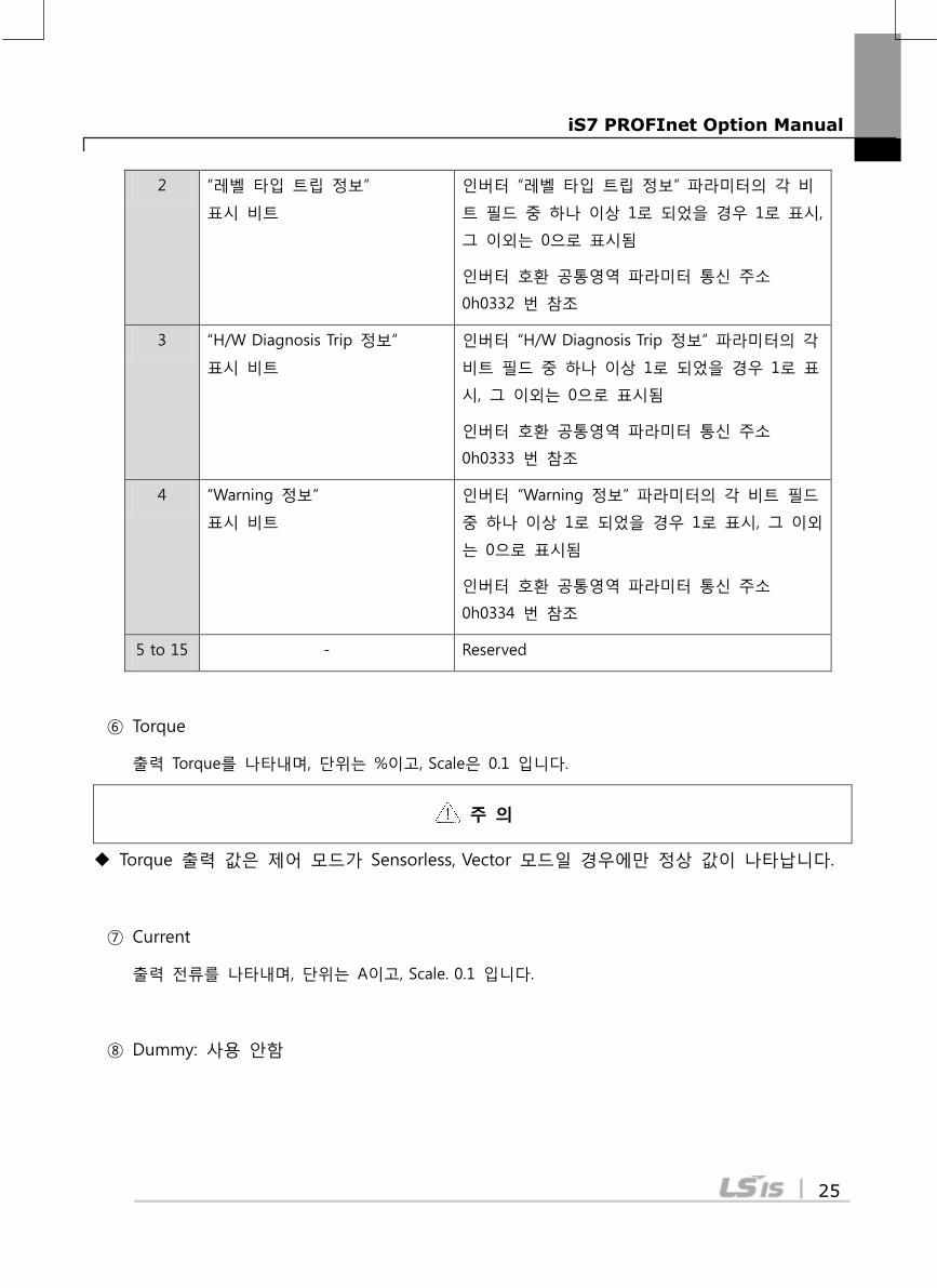
2 “레벨 타입 트립 정보”
표시 비트
인버터 “레벨 타입 트립 정보” 파라미터의 각 비
트 필드 중 하나 이상 1로 되었을 경우 1로 표시,
그 이외는 0으로 표시됨
인버터 호환 공통영역 파라미터 통신 주소
0h0332 번 참조
3 “H/W Diagnosis Trip 정보”
표시 비트
인버터 “H/W Diagnosis Trip 정보” 파라미터의 각
비트 필드 중 하나 이상 1로 되었을 경우 1로 표
시, 그 이외는 0으로 표시됨
인버터 호환 공통영역 파라미터 통신 주소
0h0333 번 참조
4 “Warning 정보”
표시 비트
인버터 “Warning 정보” 파라미터의 각 비트 필드
중 하나 이상 1로 되었을 경우 1로 표시, 그 이외
는 0으로 표시됨
인버터 호환 공통영역 파라미터 통신 주소
0h0334 번 참조
5 to 15 - Reserved
⑥ Torque
출력 Torque를 나타내며, 단위는 %이고, Scale은 0.1 입니다.
주 의
Torque 출력 값은 제어 모드가 Sensorless, Vector 모드일 경우에만 정상 값이 나타납니다.
⑦ Current
출력 전류를 나타내며, 단위는 A이고, Scale. 0.1 입니다.
⑧ Dummy: 사용 안함
iS7 PROFInet Option Manual
26
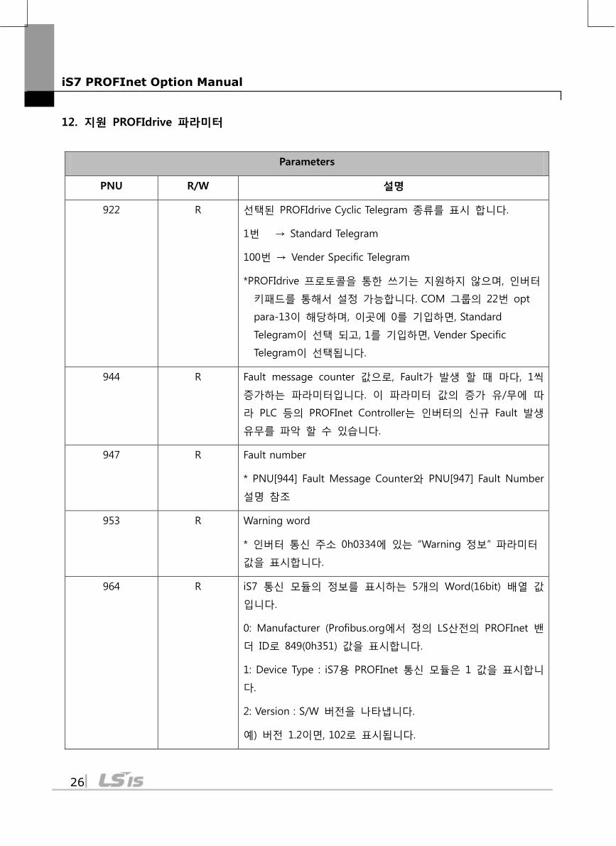
12. 지원 PROFIdrive 파라미터
Parameters
PNU R/W 설명
922 R 선택된 PROFIdrive Cyclic Telegram 종류를 표시 합니다.
1번 → Standard Telegram
100번 → Vender Specific Telegram
*PROFIdrive 프로토콜을 통한 쓰기는 지원하지 않으며, 인버터
키패드를 통해서 설정 가능합니다. COM 그룹의 22번 opt
para-13이 해당하며, 이곳에 0를 기입하면, Standard
Telegram이 선택 되고, 1를 기입하면, Vender Specific
Telegram이 선택됩니다.
944 R Fault message counter 값으로, Fault가 발생 할 때 마다, 1씩
증가하는 파라미터입니다. 이 파라미터 값의 증가 유/무에 따
라 PLC 등의 PROFInet Controller는 인버터의 신규 Fault 발생
유무를 파악 할 수 있습니다.
947 R Fault number
* PNU[944] Fault Message Counter와 PNU[947] Fault Number
설명 참조
953 R Warning word
* 인버터 통신 주소 0h0334에 있는 “Warning 정보” 파라미터
값을 표시합니다.
964 R iS7 통신 모듈의 정보를 표시하는 5개의 Word(16bit) 배열 값
입니다.
0: Manufacturer (Profibus.org에서 정의 LS산전의 PROFInet 밴
더 ID로 849(0h351) 값을 표시합니다.
1: Device Type : iS7용 PROFInet 통신 모듈은 1 값을 표시합니
다.
2: Version : S/W 버전을 나타냅니다.
예) 버전 1.2이면, 102로 표시됩니다.
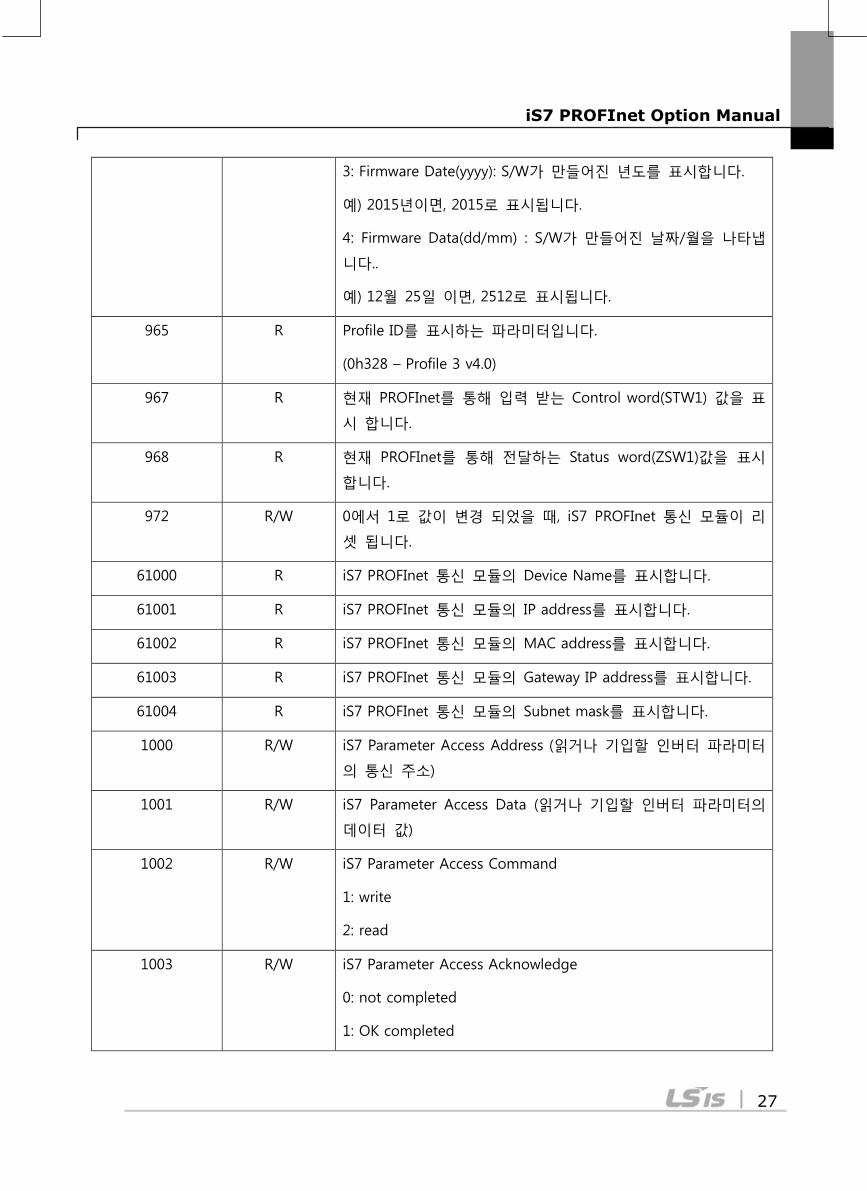
iS7 PROFInet Option Manual
27
3: Firmware Date(yyyy): S/W가 만들어진 년도를 표시합니다.
예) 2015년이면, 2015로 표시됩니다.
4: Firmware Data(dd/mm) : S/W가 만들어진 날짜/월을 나타냅
니다..
예) 12월 25일 이면, 2512로 표시됩니다.
965 R Profile ID를 표시하는 파라미터입니다.
(0h328 – Profile 3 v4.0)
967 R 현재 PROFInet를 통해 입력 받는 Control word(STW1) 값을 표
시 합니다.
968 R 현재 PROFInet를 통해 전달하는 Status word(ZSW1)값을 표시
합니다.
972 R/W 0에서 1로 값이 변경 되었을 때, iS7 PROFInet 통신 모듈이 리
셋 됩니다.
61000 R iS7 PROFInet 통신 모듈의 Device Name를 표시합니다.
61001 R iS7 PROFInet 통신 모듈의 IP address를 표시합니다.
61002 R iS7 PROFInet 통신 모듈의 MAC address를 표시합니다.
61003 R iS7 PROFInet 통신 모듈의 Gateway IP address를 표시합니다.
61004 R iS7 PROFInet 통신 모듈의 Subnet mask를 표시합니다.
1000 R/W iS7 Parameter Access Address (읽거나 기입할 인버터 파라미터
의 통신 주소)
1001 R/W iS7 Parameter Access Data (읽거나 기입할 인버터 파라미터의
데이터 값)
1002 R/W iS7 Parameter Access Command
1: write
2: read
1003 R/W iS7 Parameter Access Acknowledge
0: not completed
1: OK completed

iS7 PROFInet Option Manual
28
2: Not OK completed
iS7 PROFInet Option Manual
29
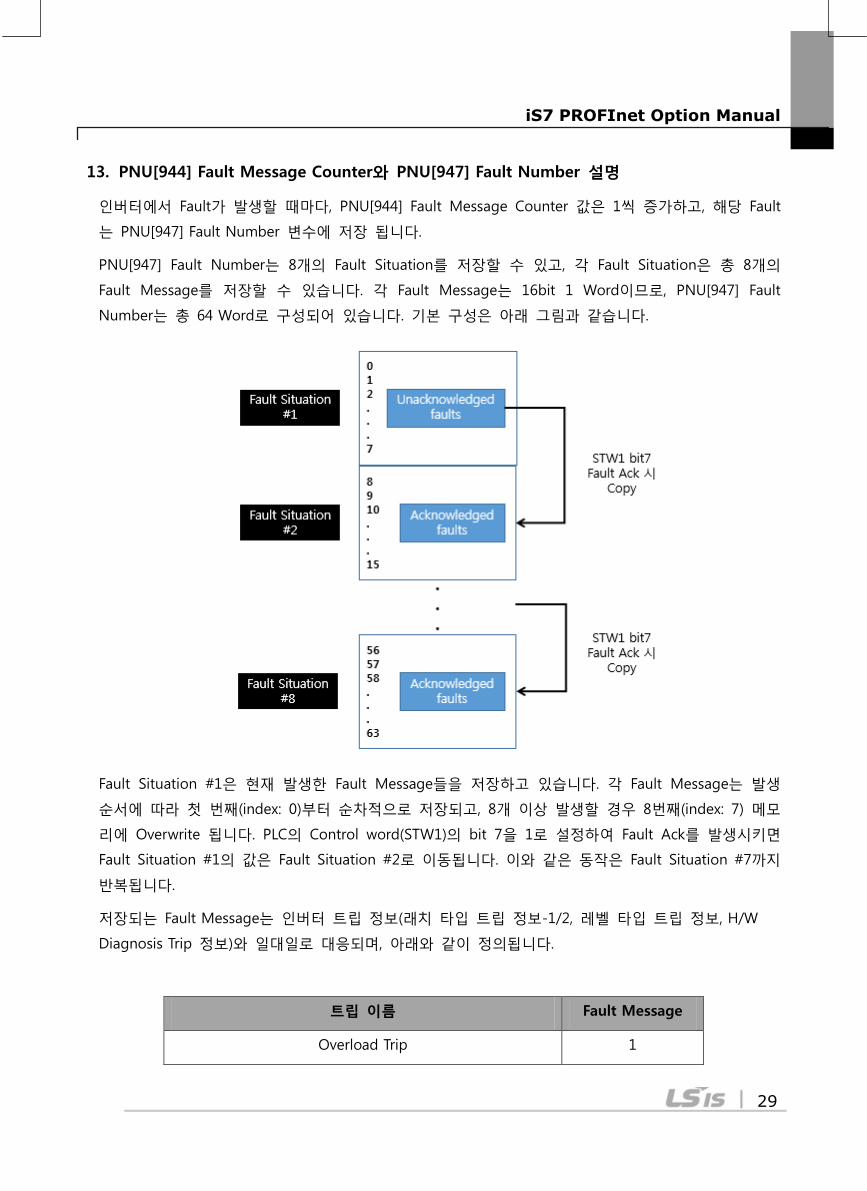
13. PNU[944] Fault Message Counter와 PNU[947] Fault Number 설명
인버터에서 Fault가 발생할 때마다, PNU[944] Fault Message Counter 값은 1씩 증가하고, 해당 Fault
는 PNU[947] Fault Number 변수에 저장 됩니다.
PNU[947] Fault Number는 8개의 Fault Situation를 저장할 수 있고, 각 Fault Situation은 총 8개의
Fault Message를 저장할 수 있습니다. 각 Fault Message는 16bit 1 Word이므로, PNU[947] Fault
Number는 총 64 Word로 구성되어 있습니다. 기본 구성은 아래 그림과 같습니다.
Fault Situation #1은 현재 발생한 Fault Message들을 저장하고 있습니다. 각 Fault Message는 발생
순서에 따라 첫 번째(index: 0)부터 순차적으로 저장되고, 8개 이상 발생할 경우 8번째(index: 7) 메모
리에 Overwrite 됩니다. PLC의 Control word(STW1)의 bit 7을 1로 설정하여 Fault Ack를 발생시키면
Fault Situation #1의 값은 Fault Situation #2로 이동됩니다. 이와 같은 동작은 Fault Situation #7까지
반복됩니다.
저장되는 Fault Message는 인버터 트립 정보(래치 타입 트립 정보-1/2, 레벨 타입 트립 정보, H/W
Diagnosis Trip 정보)와 일대일로 대응되며, 아래와 같이 정의됩니다.
트립 이름 Fault Message
Overload Trip 1
iS7 PROFInet Option Manual
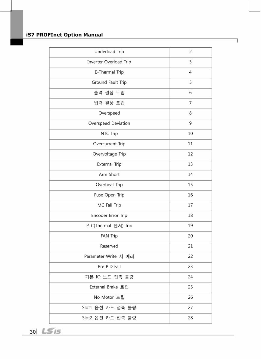
30
Underload Trip 2
Inverter Overload Trip 3
E-Thermal Trip 4
Ground Fault Trip 5
출력 결상 트립 6
입력 결상 트립 7
Overspeed 8
Overspeed Deviation 9
NTC Trip 10
Overcurrent Trip 11
Overvoltage Trip 12
External Trip 13
Arm Short 14
Overheat Trip 15
Fuse Open Trip 16
MC Fail Trip 17
Encoder Error Trip 18
PTC(Thermal 센서) Trip 19
FAN Trip 20
Reserved 21
Parameter Write 시 에러 22
Pre PID Fail 23
기본 IO 보드 접촉 불량 24
External Brake 트립 25
No Motor 트립 26
Slot1 옵션 카드 접촉 불량 27
Slot2 옵션 카드 접촉 불량 28
iS7 PROFInet Option Manual
31
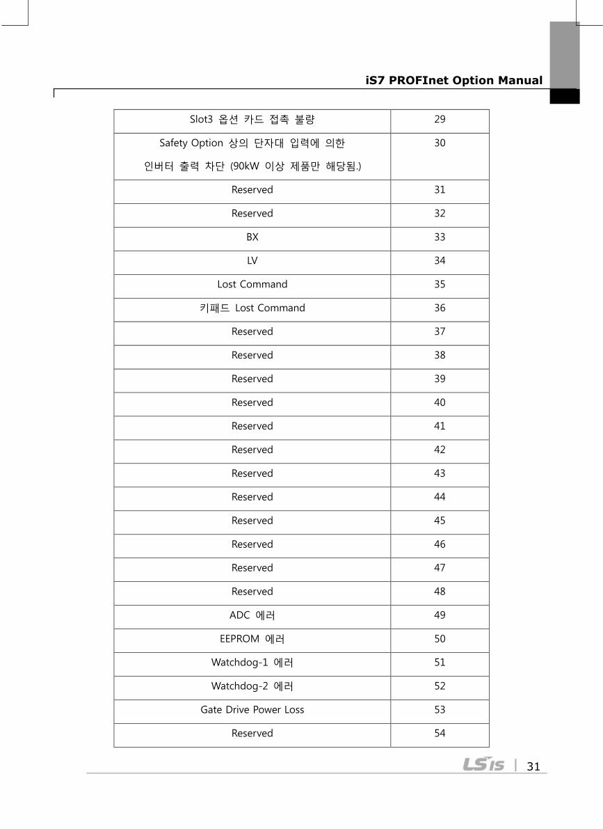
Slot3 옵션 카드 접촉 불량 29
Safety Option 상의 단자대 입력에 의한
인버터 출력 차단 (90kW 이상 제품만 해당됨.)
30
Reserved 31
Reserved 32
BX 33
LV 34
Lost Command 35
키패드 Lost Command 36
Reserved 37
Reserved 38
Reserved 39
Reserved 40
Reserved 41
Reserved 42
Reserved 43
Reserved 44
Reserved 45
Reserved 46
Reserved 47
Reserved 48
ADC 에러 49
EEPROM 에러 50
Watchdog-1 에러 51
Watchdog-2 에러 52
Gate Drive Power Loss 53
Reserved 54
iS7 PROFInet Option Manual
32
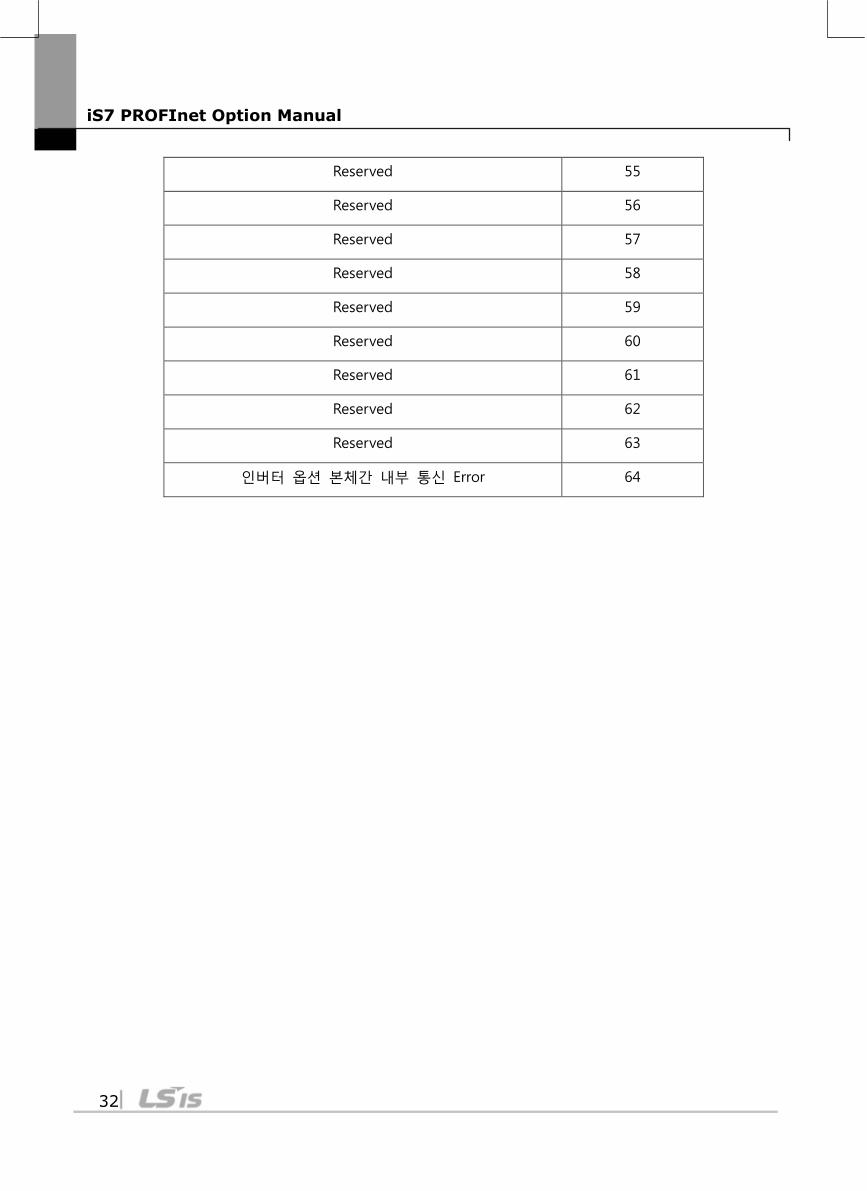
Reserved 55
Reserved 56
Reserved 57
Reserved 58
Reserved 59
Reserved 60
Reserved 61
Reserved 62
Reserved 63
인버터 옵션 본체간 내부 통신 Error 64
iS7 PROFInet Option Manual
33
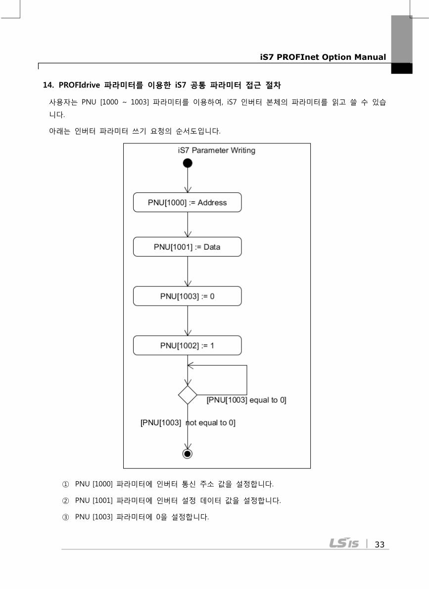
14. PROFIdrive 파라미터를 이용한 iS7 공통 파라미터 접근 절차
사용자는 PNU [1000 ~ 1003] 파라미터를 이용하여, iS7 인버터 본체의 파라미터를 읽고 쓸 수 있습
니다.
아래는 인버터 파라미터 쓰기 요청의 순서도입니다.
① PNU [1000] 파라미터에 인버터 통신 주소 값을 설정합니다.
② PNU [1001] 파라미터에 인버터 설정 데이터 값을 설정합니다.
③ PNU [1003] 파라미터에 0을 설정합니다.

iS7 PROFInet Option Manual
34
④ PNU [1002] 파라미터에 1을 설정하면 iS7 PROFInet 통신 모듈이 PNU [1000], PNU [1001] 값
을 참조하여 인버터 본체 파라미터에 저장합니다.
⑤ iS7 PROFInet 통신 모듈은 인버터 파라미터 값을 저장하고 동작 결과를 PNU [1003]에 저장
합니다.
⑥ PNU [1003] 값을 체크하여 데이터 쓰기 요청의 정상 수행 여부를 확인합니다.
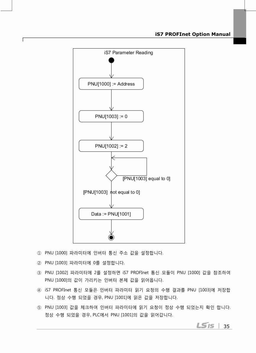
아래는 공통 파라미터 읽기 요청의 순서도입니다.
iS7 PROFInet Option Manual
35
① PNU [1000] 파라미터에 인버터 통신 주소 값을 설정합니다.
② PNU [1003] 파라미터에 0를 설정합니다.
③ PNU [1002] 파라미터에 2를 설정하면 iS7 PROFInet 통신 모듈이 PNU [1000] 값을 참조하여
PNU [1000]의 값이 가리키는 인버터 본체 값을 읽어옵니다.
④ iS7 PROFInet 통신 모듈은 인버터 파라미터 읽기 요청의 수행 결과를 PNU [1003]에 저장합
니다. 정상 수행 되었을 경우, PNU [1001]에 읽은 값을 저장합니다.
⑤ PNU [1003] 값을 체크하여 인버터 파라미터에 읽기 요청이 정상 수행 되었는지 확인 합니다.
정상 수행 되었을 경우, PLC에서 PNU [1001]의 값을 읽어갑니다.

iS7 PROFInet Option Manual
36
iS7 PROFInet Option Manual
37
15. PROFInet Record Data Object를 이용한 iS7 Parameter Access
PROFIdrive 통신 프로토콜을 사용하지 않고, 인버터의 파라미터의 값을 읽고 쓸 수 있습니다. 인버터
의 파라미터는 인덱스 0h5000를 기준으로 PROFInet Record Data에 순서대로 할당되어 있습니다. 사용
자는 PROFInet IO RW 서비스를 통해 각 파라미터를 읽고 쓸 수 있습니다. 예를 들어 Siemens PLC 사
용자는 “WRREC”와 “RDREC” Function Block를 사용하여, PROFInet Record로 Mapping된 인버터 파라미
터에 접근 할 수 있습니다. 인버터 파라미터의 내용은 해당 인버터의 매뉴얼을 참조하여 주십시오.
예) 공통영역 파라미터 통신 주소(0h0001)는 인덱스 번호 0h5001의 PROFInet Record Data에 할당 되
어 있습니다.
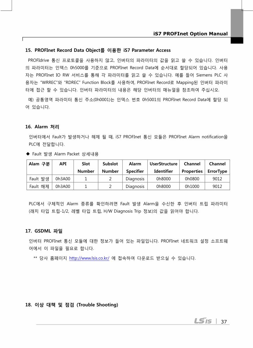
16. Alarm 처리
인버터에서 Fault가 발생하거나 해제 될 때, iS7 PROFInet 통신 모듈은 PROFInet Alarm notification을
PLC에 전달합니다.
Fault 발생 Alarm Packet 상세내용
Alam 구분 API Slot
Number
Subslot
Number
Alarm
Specifier
UserStructure
Identifier
Channel
Properties
Channel
ErrorType
Fault 발생 0h3A00 1 2 Diagnosis 0h8000 0h0800 9012
Fault 해제 0h3A00 1 2 Diagnosis 0h8000 0h1000 9012
PLC에서 구체적인 Alarm 종류를 확인하려면 Fault 발생 Alarm을 수신한 후 인버터 트립 파라미터
(래치 타입 트립-1/2, 레벨 타입 트립, H/W Diagnosis Trip 정보)의 값을 읽어야 합니다.
17. GSDML 파일
인버터 PROFInet 통신 모듈에 대한 정보가 들어 있는 파일입니다. PROFInet 네트워크 설정 소프트웨
어에서 이 파일을 필요로 합니다.
** 당사 홈페이지 http://www.lsis.co.kr/ 에 접속하여 다운로드 받으실 수 있습니다.
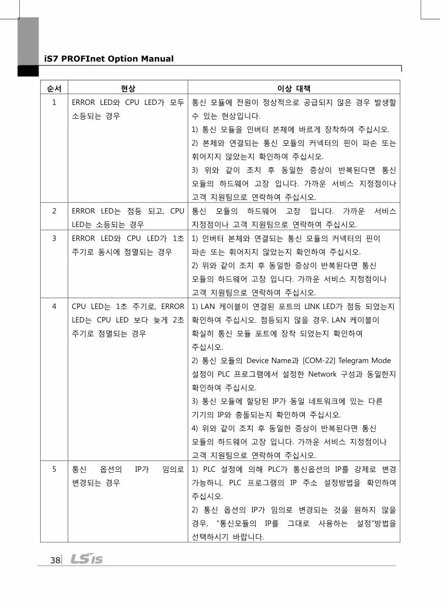
18. 이상 대책 및 점검 (Trouble Shooting)
iS7 PROFInet Option Manual
38
순서 현상 이상 대책
1 ERROR LED와 CPU LED가 모두
소등되는 경우
통신 모듈에 전원이 정상적으로 공급되지 않은 경우 발생할
수 있는 현상입니다.
1) 통신 모듈을 인버터 본체에 바르게 장착하여 주십시오.
2) 본체와 연결되는 통신 모듈의 커넥터의 핀이 파손 또는
휘어지지 않았는지 확인하여 주십시오.
3) 위와 같이 조치 후 동일한 증상이 반복된다면 통신
모듈의 하드웨어 고장 입니다. 가까운 서비스 지정점이나
고객 지원팀으로 연락하여 주십시오.
2 ERROR LED는 점등 되고, CPU
LED는 소등되는 경우
통신 모듈의 하드웨어 고장 입니다. 가까운 서비스
지정점이나 고객 지원팀으로 연락하여 주십시오.
3 ERROR LED와 CPU LED가 1초
주기로 동시에 점멸되는 경우
1) 인버터 본체와 연결되는 통신 모듈의 커넥터의 핀이
파손 또는 휘어지지 않았는지 확인하여 주십시오.
2) 위와 같이 조치 후 동일한 증상이 반복된다면 통신
모듈의 하드웨어 고장 입니다. 가까운 서비스 지정점이나
고객 지원팀으로 연락하여 주십시오.
4 CPU LED는 1초 주기로, ERROR
LED는 CPU LED 보다 늦게 2초
주기로 점멸되는 경우
1) LAN 케이블이 연결된 포트의 LINK LED가 점등 되었는지
확인하여 주십시오. 점등되지 않을 경우, LAN 케이블이
확실히 통신 모듈 포트에 장착 되었는지 확인하여
주십시오.
2) 통신 모듈의 Device Name과 [COM-22] Telegram Mode
설정이 PLC 프로그램에서 설정한 Network 구성과 동일한지
확인하여 주십시오.
3) 통신 모듈에 할당된 IP가 동일 네트워크에 있는 다른
기기의 IP와 충돌되는지 확인하여 주십시오.
4) 위와 같이 조치 후 동일한 증상이 반복된다면 통신
모듈의 하드웨어 고장 입니다. 가까운 서비스 지정점이나
고객 지원팀으로 연락하여 주십시오.
5 통신 옵션의 IP가 임의로
변경되는 경우
1) PLC 설정에 의해 PLC가 통신옵션의 IP를 강제로 변경
가능하니, PLC 프로그램의 IP 주소 설정방법을 확인하여
주십시오.
2) 통신 옵션의 IP가 임의로 변경되는 것을 원하지 않을
경우, “통신모듈의 IP를 그대로 사용하는 설정”방법을
선택하시기 바랍니다.
iS7 PROFInet Option Manual
39
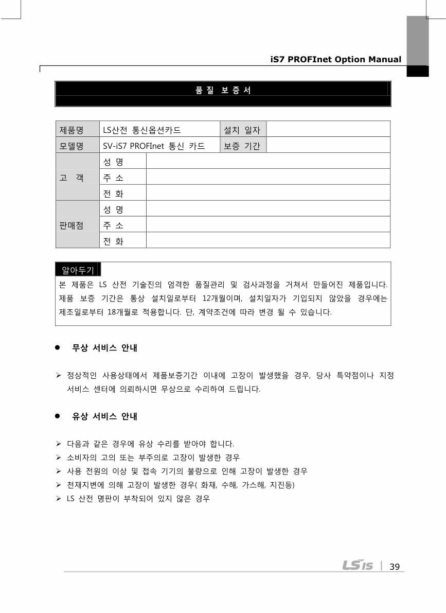
품 질 보 증 서
제품명 LS산전 통신옵션카드 설치 일자
모델명 SV-iS7 PROFInet 통신 카드 보증 기간
고 객
성 명
주 소
전 화
판매점
성 명
주 소
전 화
알아두기
본 제품은 LS 산전 기술진의 엄격한 품질관리 및 검사과정을 거쳐서 만들어진 제품입니다.
제품 보증 기간은 통상 설치일로부터 12개월이며, 설치일자가 기입되지 않았을 경우에는
제조일로부터 18개월로 적용합니다. 단, 계약조건에 따라 변경 될 수 있습니다.
무상 서비스 안내
정상적인 사용상태에서 제품보증기간 이내에 고장이 발생했을 경우, 당사 특약점이나 지정
서비스 센터에 의뢰하시면 무상으로 수리하여 드립니다.
유상 서비스 안내
다음과 같은 경우에 유상 수리를 받아야 합니다.
소비자의 고의 또는 부주의로 고장이 발생한 경우
사용 전원의 이상 및 접속 기기의 불량으로 인해 고장이 발생한 경우
천재지변에 의해 고장이 발생한 경우( 화재, 수해, 가스해, 지진등)
LS 산전 명판이 부착되어 있지 않은 경우