isel-cnc operating system 5 · 2 isel-cnc operating system 5.x on this manual various symbols are...
TRANSCRIPT

isel-CNC Operating System 5.x
Software manual
B.325/2000.18

2
isel-CNC Operating System 5.x
On this Manual
Various symbols are used in this Manual to quickly provide you with brief information.
Danger Caution Note Example Additional Information
© iselautomation 1998
All rights reserved.
Despite all care, printing errors and mistakes cannot be ruled out completely.
Suggestions for improvement and notes on errors are always welcomed.
Manufacturer: iselautomation KG
Im Leibolzgraben 16
D-36132 Eiterfeld
Fax: (06672) 898-888
e-mail: [email protected]
http://www.isel.com

3
isel-CNC Operating System 5.x
Contents
1 Introduction ........................................................................................................................ .5
2 DNC Command Structure ................................................................................................. .6
2.1 Basic Command Set for Processor Card 4.0 (and higher) .................................................. .72.1.1 Command: Set number of axes ........................................................................................... .72.1.2 Command: Reference point approach ................................................................................ .82.1.3 Command: Set reference speed ........................................................................................ .102.1.4 Command: Relative movement .......................................................................................... .112.1.5 Command: MoveTo (position) .......................................................................................... .132.1.6 Command: Position interrogation ..................................................................................... .152.1.7 Command: Zero offset ........................................................................................................ .162.1.8 Command: Select plane ..................................................................................................... .172.1.9 Command: Peek (read memory address) ........................................................................ .192.1.10 Command: Poke (write memory address) ........................................................................ .202.1.11 Command: Clear battery-backed RAM ............................................................................. .212.1.12 Command: Set CR/LF ........................................................................................................ .222.1.13 Command: Set device number .......................................................................................... .232.1.14 Command: TRACE (single-step mode) ............................................................................. .242.1.15 Command: Self-test ............................................................................................................. .25
2.2 Supplementary Command Set of Interface Card 5.0 ......................................................... .262.2.1 Command: 3D linear interpolation .................................................................................... .262.2.2 Command: Circular interpolation ...................................................................................... .28
2.3 Supplementary Command Set of Interface Cards with I/O Expansion ............................. .342.3.1 Command: Save externally ................................................................................................ .342.3.2 Command: Set output port ................................................................................................ .352.3.3 Command: Read input port .............................................................................................. .35
2.4 Supplementary Command Set of EP1090 .......................................................................... .362.4.1 Command: Output module ................................................................................................ .36
2.5 Supplementary Command Set for Interface Card, Version AZ1350/5 and Higher .......... .362.5.1 Command: Magnetic brake ............................................................................................... .36
2.6 Check and Control Codes .................................................................................................... .372.6.1 Command: Self-test ............................................................................................................ .372.6.2 Command: STOP ................................................................................................................ .382.6.3 Command: µP Reset ........................................................................................................... .392.6.4 Command: Break ................................................................................................................ .39
...

4
isel-CNC Operating System 5.x
3 CNC Command Structure.40
3.1 Basic Command Set of Processor Card 4.0 and Higher ................................................... .41
3.1.1 Command: INPUT ............................................................................................................... .413.1.2 Command: Reference Point Approach ............................................................................ .423.1.3 Command: Relative Movement ......................................................................................... .433.1.4 Command: MoveTo (position) ........................................................................................... .443.1.5 Command: Zero offset ........................................................................................................ .453.1.6 Command: Select plane ..................................................................................................... .463.1.7 Command: Transmit synchronisation character .............................................................. .473.1.8 Command: Wait for synchronisation character ................................................................ .493.1.9 Command: Loop / Branch .................................................................................................. .503.1.10 Command: Pulse Control ................................................................................................... .523.1.11 Command: Time Delay ....................................................................................................... .533.1.12 Command: Move to pulse .................................................................................................. .543.1.13 Command: Start connected interface card ....................................................................... .55
3.2 Supplementary Command Set of Interface Card 5.0 ......................................................... .563.2.1 Command: 3D Linear Interpolation ................................................................................... .563.2.2 Command: Circular interpolation ...................................................................................... .57
3.3 Supplementary Command Set of Interface Cards with I/O Expansion ............................. .593.3.1 Command: Set output port ................................................................................................ .593.3.2 Command: Read input port ............................................................................................... .61
3.4 Supplementary Command in Conjunction with a Program Selection Unit ..................... .623.4.1 Command: Keyboard polling ............................................................................................. .62
4 Error Messages ............................................................................................................... .64
4.1 Error Messages of the Processor Cards .............................................................................. .64
4.2 PAL-PC Error Messages ........................................................................................................ .68

5
isel-CNC Operating System 5.x
1 Introduction
The description of the CNC operating system 5.x is a comprehensive documentation of
all commands of isel processor cards. The commands described herein apply to the
following isel control systems:
• isel Interface Card (up to software version 5.x)
• isel CNC Controllers C 116, C 142/1, C 116-4, C 142-4
• isel CNC Control Systems C 10C, C 10C-I/O
• isel Integrated Technologies IT 108, IT 116
• isel Machining Centre EP 1090
• isel Machining Centre EP 1090/4
The CNC operating system supports the positioning of a maximum of three stepper
motor drive axes. In addition to the positioning parameters, the operating system is able
to process various control and check functions.
Due to the fact that all control systems are summarised in one operating system (called
here processor card), certain restrictions regarding the programming of the individual
devices may possibly be taken into account. These restrictions are mentioned in the
relevant hardware descriptions.
The program examples used in the Description refer to the maximum configuration. In
some cases, it may be therefore necessary to adapt the positioning commands
accordingly to the particular application.
The term ‘PAL PC’ is used both in conjunction with the programming language PAL-PC
and with the PAL-EP software interfacing module.
For direct programming of the processor cards, a defined transmission format is
provided. This Manual contains an example programmed in BASIC.

6
isel-CNC Operating System 5.x
2 DNC Command Structure
In DNC mode, data records and commands transferred from a control computer are
evaluated and executed directly. To this aim, a so-called initialisation is required prior to
the data communication. This initialisation consists of the data opening character @, the
device number (default = 0) and the number of axes to be traversed. Thereafter, the
program steps are transferred to the processor card separately and executed directly.
For checking the data transfer and providing appropriate messages in case of errors,
ASCII characters are sent back to the control computer via the interface. This so-called
hardware handshake procedure can be realised at two different times:
1. The processor card will send off the acknowledgement/error flag directly after
receiving the data record to be executed.
2. The processor card will execute the transmitted command set and will then feed back
the acknowledgement character/error flag.
The desired mode is distinguished by the use of capital/small letters for the command
character. If capital letters are used, a check-back signal is provided after the respective
command has been executed, and small letters will result in a direct check-back signal.
The command set of Interface Card 4.0 is described in the following. For amendments
resulting from hardware upgrades (e.g., Interface Card 5.0), please refer to the end of the
Chapter.
The terminal mode mentioned in the example programs is a function of the isel PAL-PC
software. It is enabled in PAL-PC using function key F2 and provides a direct link between
screen and interface card.
For further information, please refer to the PAL-PC Manual, Section X1, “Communication
Window“.

7
isel-CNC Operating System 5.x
2.1 Basic Command Set for Processor Card 4.0 (and higher)
2.1.1 Command: Set number of axes
Application The processor card is re-initialised by transmitting the number of axes.
The data memory will be cleared and, to optimise the memory, re-
allocated according to the number of axes.
Structure <GN><axes>
<GN> = device number, default = 0
<axes> = axis specification, see below
Notation @07
Explanation The card is addressed using @0; the axis configuration is specified by
the numerical value after the address.
Axis specification Value
x 1
xy 3
xz 5
xyz 7
Restrictions The combinations @00, @02, @04, @06, as well as @08 and @09 are
not allowed.
Programming example
PAL-PC GW-BASIC
#axis xyz; 100 open“com1:9600,N,8,1,DS,CD“as #1
110print#1,“@07":gosub 1000120 stop
1000 if loc(1)<1 then goto 1000
1010 a$=input$(1,1)
1015 if a$=“0" then return
1020 print “card signals error“: ;a$
1030 stop
The command Set number of axes will clear all data stored in the RAM, even if the data
have been stored in the RAM of the processor card thanks to the integrated option
Memory Back-up after a failure of the supply voltage.

8
isel-CNC Operating System 5.x
2.1.2 Command: Reference point approach
Application The processor card will traverse all specified axes to their zero points
(reference points). With isel systems, the reference points are located
in the direction towards the motor; positive movements will be carried
out in the direction from the motor away.
Structure @<GN>R<axes>
<GN> = device number, default = 0
<axes> = integer value between 1 and 7
Notation @0R7 or @0r7
Explanation The card is addressed using @0. “R“ specifies that approach to the
reference points is to be carried out. The numerical value defines the
axes to be referenced:
x = 1 xy = 3
y = 2 yz = 6
z = 4 xyz = 7
xz = 5
The order of execution is defined as follows:
—> Z axis —> Y axis —> X axis
This will also be true if an axis other than the tool axis has been
defined using the Plane command. In this case, any collisions with the
workpiece can be prevented if the individual axes are approached to
their reference points separately.
After the reference point approach has been carried out, the processor
card will send its acknowledgement flag and will wait for the
commands to come. If an immediate check-back signal is required,
use “r“ instead of “R“. The processor card, however, can execute
commands only after the mechanical system has carried out the
reference approach.
Restrictions You can use this command after an initialisation of the processor card
has been carried out using the command Set number of axes; the
command is limited to the speficied axis configuration. In case of
incorrect axis specification, error check-back signal 3 will be provided.
If the card is in 3D mode, this command will switch the card back to
2.5D mode.

9
isel-CNC Operating System 5.x
Programming example
PAL-PC GW-BASIC
#axis xyz; 100 open“com1:9600,N,8,1,DS,CD“ast#1
reference xyz; 110 print#1,“@07":gosub 1000
120 print#1,“@0R7":gosub 1000130 stop
1000 if loc(1)<1 then goto 1000
1010 a$=input$(1,1)
1015 if a$=“0" then return
1020 print ”card signals error:”;a$
1030 stop
If the reference switch is not connected, the processor card will provide pulses
continuously. By pressing the STOP key twice, however, you can abort reference point
approach of the axis concerned.
Fig. 1: Course of reference point approach
Speed
Machine zero
Time
Limit switch

10
isel-CNC Operating System 5.x
2.1.3 Command: Set reference speed
Application This command is used to define the speed at which referencing is
carried out for each axis seperately. This is only the speed at which the
axis approaches to the motor in the negative direction; the speed from
the switch cannot be controlled (see “Reference point approach“).
Structure @<GN>d<Gx> (x)
@<GN>d<Gx>, <Gy> (X-y)
@<GN>d<Gx>, <Gz> (X-z)
@<GN>d<Gx>, <Gy>, <Gz> (X-Y-z)
<GN> = device number, default = 0
<Gx> = referencing speed x
<Gy> = referencing speed y
<Gz> = referencing speed z
<Gx>, <Gy>, <Gz>= integer number between 30 and 10,000 Hz
Notation @0d2500 (1 axis)
@0d2400,3000 (2 axes)
@0d1000,3000,9000 (3 axes)
Explanation If no information on the referencing speed is transferred to the
processor, the reference points will be approached at a default speed
of 2,000 steps/s. Any modifications to the values remain stored when
the device is switched off provided the Memory Back-up option is
installed.
Restrictions -
Programming example
PAL-PC GW-BASIC
#axis xy; 100open“com1:9600,N,8,1,DS,CD“as #1
#ref_speed 3000,5000; 110 print#1,“@03":gosub 1000
120 print#1,“@0d3000,5000":gosub 1000 130 print#1,“@0R3":gosub 1000
140 stop
1000 if loc(1)<1 then goto 1000
1010 a$=input$(1,1)
1015 if a$=“0" then return
1020 print ”card signals error:”;a$
1030 stop
A too high referencing speed in conjunction with a high leadscrew pitch may cause
damage to the reference switches due to the existing mass inertia.
The processor card requires a switching hysteresis of the connected zero-position switch
(to be observed when connecting electronic zero sensors).

11
isel-CNC Operating System 5.x
2.1.4 Command: Relative movement
Application The processor card will provide a pulse sequence according to the
transferred number of steps and according to the step speed for each
power output stage. The traversing movement will either be carried
immediately or will be stored.
Structure @<GN>A<Sx>,<Gx>,<Sy>,<Gy>,<Sz1>,<Gz1>,<Sz2>,<Gz2>
<GN> = device number, default = 0
<Sx> = number of steps x, value between 0 and +/- 8,388,607
<Gx> = speed x, value between 30 and 10,000
.
.
<Gz2> = speed of Z axis (2nd movement)
Notation @0A 5000,900 (only X axis)
@0A 50,900,20,9000 (X and Y axes)
@0A 50,900,20,900,-20,900 (X and Z axes)
@0A 30,800,10,900,4,90,-4,30 (X, Y and Z axes)
Explanation The processor card is addressed using @0; “A“ specifies that a
movement is to be carried out. The processor card will now expect a
pair of numbers consisting of the number of steps and the speed for
each individual axis.
The movement is carried out in incremental dimensions, i.e. with
reference to the last position. The specified number must correspond
to the number of axes, i.e. one parameter pair for X mode, two
parameter pairs for XY mode, three parameter pairs for XZ mode and
four parameter pairs for XYZ mode. The individual numbers must be
separated by commas.
For the Z axis, two pairs of numbers are expected, since the situation
“Travelling, lowering the tool and then lifting“ very often occurs.
In 2.5D interpolation mode, first the X and the Y axes will traverse (with
linear interpolation), and then the Z axis will traverse first by the values
specified in z1 and then by the values specified in z2. This interpolation
assignment can be modified in 2D mode using the Plane command.
If only one axis is to be moved, nevertheless the values for all initialised
axes have to be transferred. When doing so, a value between 30 and
10,000 must be specified for the numbers of steps of the axes not
moved.
After the command has been executed, the processor card will provide
the handshake character (0) as the check-back signal. Making use of
the distinction between the different command codes “a“ and “A“, you
can choose between an acknowledgement message provided directly
after the transmission and a check-back signal provided after the
command has been executed. In any case, however, the processor
card can only execute commands after a command has been completed.

12
isel-CNC Operating System 5.x
Restrictions You can use this command only after the number of axes has been
set. The processor card will not check whether the movement leaves
the admissible range of the connected mechanical system.
Programming example
PAL-PC GW-BASIC
#axis xy; 100 open“com1:9600,N,8,1,DS,CD“as#1
move50(500),300(900); 110 print#1,“@03":gosub 1000
120 print#1,“@0A50,500,300,900":gosub 1000 130 print#1,“@0A20,200,-30,900":gosub 1000 140 stop
1000 if loc(1)<1 then goto 1000
1010 a$=input$(1,1)
1015 if a$=“0" then return
1020 print ”card signals error : ”;a$
1030 stop
In 2.5D interpolation mode, the speed specification of the axis with the longest travel will
be accepted as the traversing rate, and the speed of the other axis will be matched
according to the travel ratio.In contrast to this, in 3D interpolation mode, the speed specification of the X axis will be
used as the set value for the traversing rate.

13
isel-CNC Operating System 5.x
2.1.5 Command: MoveTo (position)
Application The processor card will traverse to the specified position at the
specified rates. The traversing movement will be carried out
immediately.
Structure @<GN>M<Sx>,<Gx>,<Sy>,<Gy>,<Sz1>,<Gz1>,<Sz2>,<Gz2>
<GN> = device number, default = 0
<Sx> = positional data for X axis
<Gx> = speed of X axis
.
.
<Sz2> = with absolute positioning = 0
<Gz2> = speed of Z axis (2nd movement)
Notation @0M 5000,900 (X axis)
@0M 50,900,20,9000 (X and Y axes)
@0M 50,900,20,900,0,21 (X and Z axes)
@0M 30,800,10,900,4,90,0,21 (X, Y and Z axes)
Explanation The processor card is addressed using @0. “M“ specifies that an
absolute position will follow. For sake of compatibility with the relative
positioning command, two pairs of numbers are also here expected for
the Z axis. The second position specification, however, must be zero
and will be ignored. After the command has been executed, the
processor card will send the handshake character as the check-back
signal. If you wish to be provided the check-back signal immediately,
use “m“ instead of “M“. In any case, however, the processor card can
only receive new commands after the execution of this command has
been completed.
Restrictions You can only use this command after the number of axes has been
set. It cannot be transmitted during the execution of stored
commands. The processor card will not check whether the movement
leaves the admissible range of the connected mechanical system. To
save the command, first set the processor card to Input mode (see
„Input“) and use command code “m“.

14
isel-CNC Operating System 5.x
Programming example
PAL-PC GW-BASIC
#axis xy; 100 open“com1.9600,N,8,1,DS,CD“as #1
reference xy; 110 print#1,“@03":gosub 1000
moveto 50(500),300(900); 120 print#1,“@0M50,500,300,900"moveto 20(200),30(900); 125 gosub 1000
moveto 0(21),00(2000); 130 print#1,“@0M20,200,30,900"stop. 135 gosub 1000
140 print#1,“@0M 0,21,700,2000" 145 gosub 1000
150 stop
1000 if loc(1)<1 then goto 1000
1010 a$=input$(1,1)
1015 if a$=“0" then return
1020 print ”card signals error: ”;a$
1030 stop

15
isel-CNC Operating System 5.x
2.1.6 Command: Position interrogation
Application The processor card will feed back the current set position of all axes to
the higher-level computer.
Structure @<GN>P
<GN> = device number, default = 0
Notation @0P
Explanation The processor card is addressed using @0. “P“ specifies that a
position interrogation is to be carried out. The processor card will
confirm this with the handshake character and will then output the
position values of all axes in the hexadecimal format (in total, 19 bytes
= 18 hexadecimal digits + 1 x handshake)
The structure of the fed back position is as follows:
0 000010 002000 FFFFFE
A B C
A Position x, hexadecimally, using a twin complement,
in the example, the decimal value 16.
B Position y, hexadecimally, using a twin complement,
in the example, the decimal value 8,096.
C Position z, hexadecimally, using a twin complement,
in the example, the decimal value 2.
Restrictions This command can only be used if no traversing movement is carried
out (if the plant is stopped).
The command cannot be transmitted during the execution of stored
commands.
The processor card cannot check whether the set position of the
current position corresponds to the current position of the mechanical
system, since no closed-loop control circuit exists.
Programming example
PAL-PC GW-BASIC
(terminal mode)
@0P -
In any case, the positions of all three axes are fed back by the function, irrespectively of
the number of axes defined.
The interface card will send the ASCII characters at the set transmission rates without
expecting a confirmation from the receiving computer using the hardware handshake.

16
isel-CNC Operating System 5.x
2.1.7 Command: Zero offset
Application The processor card will store the current position as a virtual zero
point for the specified axis (axes).
The next commands of the type Absolute Movement will use this virtual
zero point as the new reference point.
Structure @<GN>n<axes>
<GN> = device number, default = 0
<axes> = integer value between 1 and 7
Notation @0n7 @0n1
. .
Explanation The card is addressed using @0. “n“ specifies that a zero offset is to be
carried out. After this command, the computer will receive the
information for which axes a zero offset is to be carried out.
The assignment will be x = 1, y = 2, z = 4.
If a zero offset is to be carried out for several axes, the above values
must be added:
Axes Value Axes Value
x 1 xy 5
y 2 yz 6
z 4 xyz 7
xy 3
After the command has been carried out, the computer will provide a
check-back signal (cf Software Handshake).
Restrictions The virtual zero point is only relevant for the command AbsoluteMovement. The positioning using incremental dimensions will not be
affected by the virtual zero point, since a traversing vector is specified
here.

17
isel-CNC Operating System 5.x
Programming example
PAL-PC GW-BASIC
#axis xy; 100 open“com1:9600,N,8,1,DS,CD“as #1
#elev 4,4; 110 print#1,“@03":gosub 1000
moveto 80(900),8(900); 120 print#1,“@0r3":gosub 1000
null xy; 130 print#1,“@A1000,2000,2000,2000":gosub 1000
moveto 2(900),4(990); 140 print#1,“@0n3":gosub 1000stop. 150 print#1,“@M100,2000,100,2000":gosub 1000
160 stop
1000 if loc(1)<1 then goto 1000
1010 a$=input$(1,1)
1015 if a$=“0" then return
1020 print ”card signals error: ”;a$
1030 stop
Referencing will relocate the virtual zero point to the plant zero point.
2.1.8 Command: Select plane
Application 2.5D interpolating processor cards (e.g. Interface Card 4.0) can
interpolate only two of three axes. These are the X and Y axes
(provided they are turned on). The Select Plane command, however,
can be used to define any plane configuration other than the main
plane. The remaining third axis will be considered as the tool axis and
will then be traversed, i.e. after positioning of the main axes.
Structure @<GN>e<plane>
<GN> = device number, default = 0
<plane> = a number between 0 and 2
0 = xy
1 = xz
2 = yz
Notation @0e1 Switch to xz interpolation
@0e0 Switch to xy interpolation
Fig. 2: Switch-selectable interpolation planes
Plane 0 (xy) Plane 1 (xz) Plane 2 (yz)

18
isel-CNC Operating System 5.x
Explanation To achieve high speeds (a maximum axis speed of 10 kHz
corresponds to a vector speed of 175 mm/s in half-step mode at a
leadscrew pitch of 5 mm and a vector of 45°), the processor card can
calculate only the speed ratios of two axes another to one within this
time. The Plane command can be used to switch between the
interpolation planes without loss in speed.
Restrictions If an interpolation plane other than XY is selected, zero should be
transferred as the number of steps for the second movement of the
machining axis.
Programming example
PAL-PC GW-BASIC
#axis xyz; 100 open“com1.9600,N,8,1,DS,CD“as #1
line yz; 110 print#1,“@07":gosub 1000
move 20(1000),30(1000), 120 print#1,“@0e2” 33(1000),0(30); 125 gosub 1000
stop. 130 print#1,“@0M20,200,30,900,33,900, 0,21”
135 gosub 1000
140 stop
1000 if loc(1)<1 then goto 1000
1010 a$=input$(1,1)
1015 if a$=“0" then return
1020 print ”card signals error: ”;a$
1030 stop
In the example above, the Y and Z axes are interpolated (traversed to the target position
along a straight line), and the X axis follows up.
The plane selection has no influence on the referencing order.
If you wish to modify the referencing order, do not transfer referencing commands that
contain axis combinations.
19
isel-CNC Operating System 5.x
2.1.9 Command: Peek (read memory address)
Application The Peek command can be used to poll the contents of a memory cell
of the processor card both in the data memory and in the read-only
memory via the serial interface.
Structure @<GN>c<Addr> (read-only memory)
@<GN>b<Addr> (random-access memory)
<GN> = device number, default = 0
<Addr> = address between 0 and 65,536
Notation @0c 2048
@0b 4711
Explanation The card is addressed using @0. “c“ specifies that a value is to be read
from the read-only memory. “2048“ specifies the address of the value
to be read. The computer will reply with the software handshake
followed by two characters that specify a hexadecimal value
corresponding to the contents of the memory cell. To read a value
from the data memory, use command code “b“ instead of “c“.
Restrictions -
Programming example
PAL-PC GW-BASIC
(terminal mode)
@0b 65531 -
This command is used in its extended form in conjunction with an I/O expansion unit
(see Section 2.3.3, Commands that can be stored: Read input port).

20
isel-CNC Operating System 5.x
2.1.10 Command: Poke (write memory address)
Application The Poke command can be used to modify the contents of the data
memory of a processor card.
Structure @<GN>B<Addr>,<Data>
<GN> = device number, default = 0
<Addr> = address between 0 and 65,535
<Data> = value between 0 and 255
Notation @0B 33211,128
Explanation The card is addressed using @0. “B“ specifies that a value is to be
written into the memory. “33211“ specifies the address of the value to
be written. “128“ is the new value of this memory cell.
The computer will confirm the execution of the command with the
software handshake.
Restrictions The command will not check whether a device connected to the data
bus has accepted the data correctly.
Programming example
PAL-PC GW-BASIC
(terminal mode)
@0B33211,128 -
This command should not be used to modify internal card parameters, since the card
address may change without prior notice. The command should not be used with
addresses less than 32767, since these addresses are used by the processor card as the
data memory.

21
isel-CNC Operating System 5.x
2.1.11 Command: Clear battery-backed RAM
Application This command is used to delete all RAM data even if they are stored
quasi-continuously thanks to the Memory Back-up option. This
operation will also reset any information on reference speed, axes etc.
Structure @<GN>k (directly)
<GN> = device number, default = 0
Notation @Ok
Explanation The card is addressed using @0. “k“ specifies that the battery-backed
RAM is to be cleared. After this command has been executed, the
computer will provide an appropriate check-back signal (cf Software
Handshake).
Programming example
PAL-PC GW-BASIC
(terminal mode)
@0k 100 open“com1:9600,N,8,1,DS,CD“as #1
110 print#1,“@Ok“:gosub 1000
120 stop1000 if loc(1)<1 then goto 1000
1010 a$=input$(1,1)
1015 if a$=“0" then return
1020 print ”card signals error: ”;a$
1030 stop
If the RAM can no longer be cleared in this way, remove it from its socket for a short
moment and then reinsert it.

22
isel-CNC Operating System 5.x
2.1.12 Command: Set CR/LF
Application When receiving data, some computers must be provided with a
delimiter character at the serial interface. This is an operating system-
specific feature of some process computers (e.g., DEC VAX, HP
process computers).
The process computer needs the delimiter character to be able to
initiate an interrupt for the received process at the end of the data
transfer.
If you are using an MS-DOS computer (IBM-PC, XT, AT or the like),
this command should not be used.
Structure @<GN>C<STATUS> (directly)
<GN> = device number, default = 0
<STATUS> = 0 = OFF (default), 1 = ON
Notation @0C1
Explanation The card is addressed using @0. “C“ specifies that the software
handshake is to be modified. In this case, with all commands, the card
will check back with the sequence:
Error CHR(13) CHR(10)
Restrictions The card can then only be addressed using the new protocol.
To switch to the new protocol, use the new protocol for transfer.
A programming example cannot be specified here, since neither PAL-PC, nor GW-BASIC
is available on such process computers.

23
isel-CNC Operating System 5.x
2.1.13 Command: Set device number
Application This command is used to modify the device number of the process
card (<GN>). Numbers between 0 and 9 (chr(48) ... chr(58)) are
admissible. The new device number remains active until the device is
switched off.
Structure @<GN>G<GNnew> (directly)
<GN> = device number, default = 0
<GNneu> = character between 0 and 9
Notation @0G1
Explanation The card is addressed using @0. “G“ specifies that a new device
number is to be used to address the card.
After “G“, the card will expect the new device number.
After storing, the computer will provide an appropriate check-back
signal (cf Software Handshake).
Restrictions The card can then only be addressed using this device number. The
card will not check whether an admissible device number is
transferred.
Programming example
PAL-PC GW-BASIC
(terminal mode)
@0G1 100 open“com1:9600,N,8,1,DS,CD“as #1
110 print#1, ”@03":gosub 1000
120 print#1,”@0G1":gosub 1000 130 print#1,“@1i“:gosub 1000
140 print#1,“m 8000,900,800,900":gosub 1000
150 print#1,“n 3":gosub 1000
160 print#1,“m 200,900,400,990":gosub 1000
170 print#1,“9":gosub 1000
180 print#1,“@1S“:gosub 1000
190 stop
1000 if loc(1)<1 then goto 1000
1010 a$=input$(1,1)
1015 if a$=“0" then return
1020 print ”card signals error: ”;a$
1030 stop
To address a processor card with a modified device number in PAL-PC, use the
command #GN. In this case, the processor card can only be addressed using this device
number.

24
isel-CNC Operating System 5.x
2.1.14 Command: TRACE (single-step mode)
Application This command will cause the processor card to execute the stored
commands separately. After each command, the processor card waits
for a character at the serial interface, and the command count is
output with all relevant parameters.
Structure @<GN>t
<GN> = device number, default = 0
Notation @0t
Explanation The processor card will carry out the commands as usual; prior to
each command, however, the command count is output as an integer
number. After the command count, the command number and the
operation constant with the relevant data is output. The line is
completed with CR. The computer will then wait for a character at the
interface. Then the command is executed. With each command to be
executed, the function will behave as follows:
(A): The trace string is output (see below).
The card is waiting for a character.
If character = 127 is provided, the microprocessor will be reset.
The command will be carried out.
The command = end of data field will complete the process.
Otherwise, the next cmmand wil be provided after (A).
The trace string transferred with each command has following structure:
Structure 01234 00001 30 000001 FE87 ... FFFF01 FE01
A B C D E F G
A Memory pointer - specifies where the command is stored in the
memory of the processor card.
B Command counter - specifies the number of the current NC command.
C NC command code - specifies the command to be output.
The command is specified hexadecimally with reference to the
ASCII value of the corresponding command code. In the example
above, the command 0 = relative movement is stored.
D Command parameter of X axis; in the example above, the
representation of the distance to be traversed is a 24-bit
hexadecimal number using the twin complement mode of
representation.
E Speed value of X axis; to reconvert the speed, the fraction
921600/(high byte*(256-low byte) can be generated.
F Command parameter as D, but for the z2 specification.
G Speed specification for the z2 specification.
As with other commands, the parameters will be stored in the
transferred order either as a character or as a twin complement.

25
isel-CNC Operating System 5.x
With synchronisation commands, first the character for the trace function must be
transferred and then the synchronisation character. To switch the execution of the
individual steps, do not use the characters <spacebar>, <TAB> and <linefeed>.
To exit Trace mode, either switch off the processor card or transfer DEL (char(127)) if a
character is requested.
In the individual software versions, the order and mode of saving of the parameters is
subject to changes within the framework of the technical progress without prior notice.
The number of command parameters sent back corresponds to the number of axes
selected.
2.1.15 Command: Self-test
Application This command is used to initiate a self-test of the processor card.
In contrast to the self-test initiated by actuating the start button, this
command is only used to carry out the first part of the subroutine, and
not the traversing and interface test.
Structure @<GN>? (directly)
<GN> = device number, default = 0
Notation @0?
Explanation The card is addressed using @0. “?“ specifies that a self-test is to be
carried out. The card will then test the memory area, processor and
processor register, as well as the internal memory areas. Then some
processor card-related variables and a checksum are output.
To carry out the expanded self test, hold down the Start button and
turn on the device.
To exit the self-test, first turn off the device; no other commandscan be transferred unless the self-test is completed!
Programming example
PAL-PC GW-BASIC
(terminal mode)
@0? -
To be able to transfer further commands to the processor card, first the self-test must be
completed. Otherwise, a list character (error @) will be sent as an error message. In this
case, error 164 will be signalled to the PAL-PC.

26
isel-CNC Operating System 5.x
2.2 Supplementary Command Set of Interface Card 5.0
2.2.1 Command: 3D linear interpolation
Application Interface Card 5.0 expands the 2.5D interpolation of the standard
operating system to a 3D interpolation.
You can use this command to enable/disable the interpolation as
required for the particular task in question.
Structure @<GN>z<STATUS>
<GN> = device number, default = 0
<STATUS> = 0 - 3D interpolation OFF
= 1 - 3D interpolation ON
Notation @0z1
Explanation The data opening part @0 will prepare the processor card for a new
command. “z1“ will modify the interpolation from 2-axis to 3-axis
operation.
The instruction has a modal effect, i.e. all MOVE and MOVETO
instructions are carried out as 3D statements. The specification of z2
parameters will be ignored in these traversing movements.
The specification of the speed for the interpolation must be performed
with the X specification.

27
isel-CNC Operating System 5.x
Programming example
PAL-PC GW-BASIC
#axis xyz; 100 open“com1:9600,N,8,1,DS,CD“as #1
reference xyz; 110 print#1,“@07":gosub 1000
set3don; 120 print#1,“@0r7":gosub1000
move 10(700),15(800),3(400), 130 print#1,“@0z1":gosub 1000 0(30); 140 print#1,“@0A100,700,150,800,30,400,0,30"
set3doff; 145 gosub 1000
150 print#@1,“@0z0":gosub10001000 if loc(1)<1 then goto 1000
1010 a$=input$(1,1)
1015 if a$=“0" then return
1020 print ”card signals error: ”;a$
1030 stop
Referencing will switch back the system automatically to 2.5D interpolation.
The correct processing of a 3D interpolation requires an XY plane as the reference plane
(cf Plane Selection).
The maximum speed for a 3D interpolation is 10,000 steps/s.
The speed that can be achieved by the mechanical system depends on the connected
motors and power sections.
To carry out movements at rapid traverse, you should switch to 2D interpolation for a
short time and carry out positioning with the Z axis lifted, since no collision check is
carried out during a 3D interpolation.
In case of a 3D interpolation, the current position will not be correct after a Stop
command.
The position interrogation will provide the correct values only after the command has
been executed successfully.

28
isel-CNC Operating System 5.x
2.2.2 Command: Circular interpolation
Application This command is used for processing circles and arcs at constant
traversing rate. The circular interpolation is initiated by two successive
commands. The first command defines the circle direction, and the
second one is used to transfer the interpolation parameters.
Structure Circle direction: @<GN>f-1 CCW
@<GN>f0 CW
Arc: @<GN>y B,V,D,Xs,Ys,Rx,Ry
B = arc length in steps
V = speed (30 ... 10,000)
D = interpolation parameter
Xs = start point x
Ys = start point y
Rx = direction x
Ry = direction y
Calculating the parameters
Arc length B The arc length specifies the length of the arc between the starting and
the end points of the interpolation in steps. To calculate this
parameter, you can also use the program parts listed below. The
following rule applies:
A - starting angle of arc or circle segment
A = pi*starting angle/180
E - end position of movement
E = pi*end angle/180
B - resulting arc length
To calculate the arc length, you may only use angles specified in arc dimension.
1. Approximating formula (only with quarter, semi and full circles) B = 4*radius*(E-A)/pi

29
isel-CNC Operating System 5.x
2. Calculating the arc length using a software routine
if (circle direction=CCW) then
begin
while(A<0) do A:=A+2.0*pi;
while(E<0) do E:=E+2.0*pi; {scale angle to positive range}
while (A>=pi/2.0) do
begin
A:=A-pi/2;
E:=E-pi/2;
end;
B:=0.0;
while (E-A>=pi/2.0) do
begin
E:=E-pi/2.0;
B:=B+2.0*radius;
end;
B:=B+raduis*(cos (A) -cos (E) +sin (E) -sin (A));
end;
else {circle direction = CW}
begin
while (A>0) do A:=A-2.0*pi;
while (E>0) do E:=E-2.0*pi; {scale angle to positive range}
while (A<=-pi/2.0) do
begin
A:=A+pi/2;
E:=E+pi/2;
end;
B:=0.0;
while (A-E>=pi/2.0) do
begin
E:=E+pi/2.0;
B:=B+2.0*radius;
end;
B:=B+radius*(cos (A) -cos (E) +sin (A) -sin (E));
end;
if (B<0) then B:= -B;
The calculated arc length must be transferred to the next, integer value as a rounded
value. Values ranging from 3 to 8,000,000 are admissible in steps.

30
isel-CNC Operating System 5.x
The velocity V
Integer values ranging from 30 to 10,000 steps/s are admissible for the velocity.
Whether and at which velocities the interpolation can be carried out, depends on the
power sections used and the mechanical system connected.
The directions Rx and Ry
The parameters Rx and Ry are used to tell the processor card in which quadrant of the
circle the processor card the interpolation will start.
Counter Clockwise Clockwise
(CCW) (CW)
The starting points Xs and Ys
These parameters specify the starting points Xs and Ys relative to the circle centre.
The following formulas are used for calculating:
Xs = radius * cos(A)
Ys = radius * sin(A)

31
isel-CNC Operating System 5.x
The interpolation parameter D
“D“ has to be transferred, since the processor card is not able to calculate this parameter
due to its memory capacity.
For calculation, you can use the program section below:
function sum(xx:real):real;
begin
if(xx>0) then
sum:=xx*(xx+1)
else
sume:= -xx*(xx-1)
end;
function formel:real;
begin
if (circle direction=CCW) then
formula:= (Rx*Ry*radius+Rx*Ry*sum(radius-1.0)
-Rx*sum(Xs+(Rx-Ry)/2.0)+Ry*sum(Ys+(Rx+Ry)/2.0))/2;
else {direction = CW}
formula:= (-Rx*Ry*radius-Rx*Ry*sum(radius-1.0)
- Rx*sum(Xs+(Rx+Ry)/2.0) + Ry*sum(Ys+(Ry-Rx)/2))/2;
end;
D:=formula;
The calculated parameter must be transferred as a rounded and integer value.

32
isel-CNC Operating System 5.x
Programming example for calculating the parameter:
A quarter arc CCW circle (90°) having a radius of 200 steps and a traversing rate of 1,500
steps/s is to be carried out. The starting angle is 135°.
1. Angle specified in arc dimension:
A = pi*135/180
= 3*pi /4
B = pi* (135+90) /180
= 5*pi /4
2. Arc length: (using the approximation formula)
B = 4*radius*(E-A) /180
= 2*200*(5*pi /4-4*pi) /pi
= 400
3. Directions Rx, Ry:
Starting angle= 135°, CCW
Rx = - 1
Ry = - 1
4. Starting positions Xs, Ys:
Xs = radius*cos(starting angle)
= 200*cos(135)
= -141
Ys = radius*sin(starting angle)
= 200*sin(135)
= 141

33
isel-CNC Operating System 5.x
5. Interpolation parameter D: (CCW)
D = (Rx*Ry*radius + Rx*Ry*sum(radius -1.0)
- Rx*sum(Xs+(Rx-Ry) /2.0) + Ry*sum(Ys+(Rx+Ry) /2.0)) /2
Sum(radius-1) = sum (200-1)
= sum (199)
= 199*(199+1)
= 39 800
Sum(Xs+(Rx-Ry) /2.0)
= sum (-141 + (-1 -(-1)) /2.0)
= sum (-141)
= -(-141)*((-141) -1)
= - 20 022
Sum (Ys+(Rx+Ry) /2.0) = sum (141 +(-1 +(-1)) /2.0)
= sum (141-1)
= 140*(140+1)
= 19 740
D = (Rx * Ry*radius + Rx* Ry*39800 - Rx*(-20022) + Ry*19740) /2
= ((-1)*(-1)*200 + (-1)*(-1)*39800 - (-1)*(-20022) + (-1)*19740) /2
= ( 200 + 39800 - 20022 - 19740) /2
= 119
The program section must look as follows:
...
...
@0f-1
@0y400,1500,119,-141,141,-1,-1
...
...
or, in the direct format:
...
...
f-1
y400,1500,119,-141,141,-1,-1
...
...
9
@0s

34
isel-CNC Operating System 5.x
2.3 Supplementary Command Set of Interface Cards with I/O Expansion
2.3.1 Command: Save externally
Application This command is used to save a CNC program on an external storage
medium.
Structure @<GN>u
<GN> = device number, default = 0
Explanation This command can be used to save a CNC program currently stored
in the data memory of the processor card on a data memory in check
card format (memory card) or to read it back from a memory card to
the processor card.
When doing so, observe the following sequence:
1. Transfer from processor card to memory card
a) Transfer your program to the processor card as usual.
b) Insert the memory card.
c) Transfer the @0u command.
d) Remove the memory card.
2. Transfer from memory card to processor card
a) Turn on the controller.
b) Insert the memory card.
c) Push µP Reset.
d) Remove the memory card.
When turning on the control system, the memory card should not be installed. With the
memory card types 8 k x 8 and 16 k x 8, the existing memory capacity will not be
checked, i.e. in case of complex programs, the memory limits may be exceeded without
error message.

35
isel-CNC Operating System 5.x
2.3.2 Command: Set output port
Application The processor card will set a defined output pattern at the defined
output port of the I/O unit.
Structure @<GN>B<ADDRESS>, <VALUE>
<GN> = device number, default = 0
<ADDRESS> = output port 1 ——> 65 529
= output port 2 ——> 65 530
<VALUE> = 0 ... 255
Explanation This command corresponds to a large degree to the Poke command
of the standard operating system 5.x. During CNC operation (memory
mode), in addition to byte-by-byte processing, bit-by-bit processing of
the output ports is possible, allowing you to set or delete individual
bits separately.
2.3.3 Command: Read input port
Application The processor card will read in the bit pattern provided at the input
port of the I/O expansion.
Structure @<GN>b<ADDRESS>
<GN> = device number, default = 0
<ADDRESS> = input port 65 531
Explanation The structure of this command is identically to that of the Peekcommand used in the standard operating system 5.x. In addition, in
memory mode (CNC operation), it is possible to carry out backward
and forward branches, depending on the bit pattern.

36
isel-CNC Operating System 5.x
2.4 Supplementary Command Set of EP1090
2.4.1 Command: Output module
Application This command is used to connect/disconnect the main spindle, i.e.
the interface card will switch on/switch off the main spindle.
Structure @<GN>h<parameter> (DNC)
h<parameter> (can be stored)
<GN> = device number, default =0
<Parameter> = 1 Main spindle ON
= 0 Main spindle OFF
Notation @0h1
Explanation The card is addressed using @0. “h“ specifies that the output module
is to be switched. Parameter “1“ will switch on the integrated relay. If
the spindle is already in the ON condition, the command will have no
effect. The current condition of the main spindle is indicated by the
decimal point of the 7-segment display.
After the command has been executed, the computer will check back
“0“.
2.5 Supplementary Command Set for Interface Card, Version AZ1350/5and Higher
2.5.1 Command: Magnetic brake
Application This command can be used for software-controlled enabling/disabling
of a special output that controls magnetic brakes in drive units.
Structure @<GN> g <status>
<GN> = device number
<Status> = 1 Brake magnetised
= 0 Brake inactive
Notation @0g1
Explanation The card is addressed using @0, “g“ specifies that the brake relay is to
be switched. Status “1“ will turn on the relay. This will activate a
connected magnetic brake and will release the driving axis of the
motor. In 0 condition, the brake will not be supplied with current, thus
braking the driving axis of the motor.
After this command has been carried out, the computer will check
back “0“.

37
isel-CNC Operating System 5.x
2.6 Check and Control Codes
Check and control codes provide direct access to the sequence of functions of the
interface card via the serial interface. The transmitted commands are carried out without
delay.
2.6.1 Command: Self-test
Application The processor card will test the operational performance of its function
modules.
Structure chr(252)
Explanation The interface card will check the capacity of its data memory, the
checksum of its operating EPROM and the switch position of the DIP
switch. Then, for testing the connected stepper motors, some clock
pulses are output to the power electronics of the X and Y axes. The
test routine is completed by a permanent output of an ASCII character
set via the serial interface.
Restrictions -
Programming example
PAL-PC GW-BASIC
(terminal mode)
chr(252) -
You can complete the self-test only if you turn off the supply voltage or carry out a µP
reset.

38
isel-CNC Operating System 5.x
2.6.2 Command: STOP
Application The processor card will interrupt the current traversing movement.
Structure chr(253)
Explanation In DNC mode, a positioning movement (relative or absolute) can be
interrupted by a STOP command without step losses. A START pulse
executed after the STOP command will complete the interrupted
sequence of functions. Furthermore, you can read back the currently
reached position after a STOP command using the PositionInterrogation command.
Restrictions You can use the command only if a positioning movement is carried
out.
Programming example
PAL-PC GW-BASIC
(terminal mode)
chr(253) -
The processor card will feed back the stop error as the acknowledgement signal.
Since the command operates without addressing, the traversing movements of all
connected processor cards will be interrupted.
The higher-level computer must retransmit the position to be approached last in DNC
mode.

39
isel-CNC Operating System 5.x
2.6.3 Command: µP Reset
Application The processor card will abort all activities immediately and will change
to the RESET state.
Structure chr(254)
Explanation A µP reset will switch back the integrated microcontroller to its initial
state without delay. During the reset state, the outputs have Vcc
potential and will switch off when the GND potential is no longer
present.
Restrictions -
Programming example
PAL-PC GW-BASIC
(terminal mode)
chr(254) -
2.6.4 Command: Break
Application The Break command is used to cancel the current positioning
process.
Structure chr(255)
Explanation Sending off a Break command will cancel the current positioning
process of the interface card without initiating a stop ramp. Any
resulting step errors will be ignored. In contrast to the µP reset
command that has a similar effect, you can go on working after the
Break command as usual without reinitialising the processor card.
Restrictions -
Programming example
PAL-PC GW-BASIC
(terminal mode)
chr(255) -

40
isel-CNC Operating System 5.x
3 CNC Command Structure
In CNC mode, the processor card stores all transmitted commands in the internal data
memory. To activate them, the command @<device number>i has to be transferred
after the standard initialisation with @<device number> <number of axes>. Then the
data file is transferred and completed using command 9 as the end-of-data-field
character. Now you can reactivate the program using an external Start command.
For starting, you can use both a Start button (e.g., on the front panel of the processor
card) and the command @<device number>S.
Due to the physically limited RAM of the processor cards, the number of commands that
can be stored is limited to approx. 1,200 in 3-axis mode, approx. 1,800 in 2-axis mode
and approx. 2,400 in 1-axis mode.
In order to avoid data loss in the RAM in case of failure of the supply voltage (e.g., when
the supply voltage is switched off), a so-called memory backup can be provided by
installing an accumulator or a primary cell available as options.
The commands that can be stored are listed and explained in brief below. For a detailed
explanation, please refer to direct mode of the corresponding command.

41
isel-CNC Operating System 5.x
3.1 Basic Command Set of Processor Card 4.0 and Higher
3.1.1 Command: INPUT
Application This command will set the processor card to the memory mode.
All next following commands will be stored in the internal data
memory. The stored commands can be executed using either the Start
command or pressing the Start button.
Structure @<GN>i
<GN> = device number, default = 0
Notation @0i
Explanation The card is initialised using @0. “i“ specifies that commands follow,
which are to be stored. After the command has been received, the
processor card expects a complete NC program consisting of
commands that can be stored. This program has to be completed
using an end-of-data-field character (9).
The data field may contain all commands that can be stored.
Restrictions You can use the command only after the number of axes has been set,
i.e. the processor card has been initialised.
Programming example
PAL-PC GW-BASIC
#axis xy; 100 open“com1:9600,N,8,1,DS,CD“as #1
move 50(100),40(100); 110 print#1,“@03":gosub 1000
stop. 120 print#1,“@0i“:gosub 1000#start 130 print#1,“0 50,100,40,100":gosub 1000
140 print#1,“9":gosub 1000
150 print#1,“@0S“:gosub 1000
1000 if loc(1)<1 then goto 1000
1010 a$=input$(1,1)
1015 if a$=“0" then return
1020 print ”card signals error:”;a$
1030 stop
The Input command will delete all statements stored to date. The processor card will then
expect a complete data field, comleted with the end-of-data-field character (9).
If an error occurs during the transfer of the commands to be transferred, the processor
card will quit the Input mode, and the NC program transferred to date get lost.

42
isel-CNC Operating System 5.x
3.1.2 Command: Reference Point Approach
Application The processor card will traverse all specified axes to their zero points
(reference points).
Structure 7<axes>
<axes> = integer value between 1 and 7
Explanation “7“ specifies that reference point approach is to be carried out.
The following numerical value defines all axes to be referenced.
x = 1 xz = 5
y = 2 yz = 6
xy = 3 xyz = 7
z = 4
The order of execution is defined as follows:
—> Z axis —> Y axis —> X axis
This is also true if an axis other than the tool axis has been defined
using the Plane command. As required, approaching of the individual
axes to their reference points separately may avoid collisions with the
workpiece.
Programming example
PAL-PC GW-BASIC
#axis xyz; 100 open“com1:9600,N,8,1,DS,CD“as #1
reference xyz; 110 print#1,“@07":gosub 1000stop.
120 print#1,“@0i“:gosub 1000
130 print#1,“77":gosub 1000 140 print#1,“9":gosub 1000
1000 if loc(1)<1 then goto 1000
1010 a$=input$(1,1)
1015 if a$=“0" then return
1020 print ”card signals error:”;a$
1030 stop
(see Reference Point Approach command, Section 2.1.2)

43
isel-CNC Operating System 5.x
3.1.3 Command: Relative Movement
Application According to the transferred number of steps and the step velocity, the
processor card provides a certain step sequence for each power
output stage.
The traversing movement will either be carried out immediately or stored.
Structure 0 <Sx>,<Gx>,<Sy>,<Gy>,<Sz1>,<Gz1>,<Sz2>,<Gz2>
0 = relative movement
<Sx> = number of steps x, value between 0 and ± 8,388,607
<Gx> = veloxity x, value between 30 and 10,000
.
.
<Gz2> = velocity of Z axis (2nd movement)
Explanation “0“ specifies that a relative movement is to be carried out.
The processor card will now expect a pair of numbers consisting of the
number of steps and the speed for each axis.
Programming example
PAL-PC GW-BASIC
#axis xyz; 100 open“com1:9600,N,8,1,DS,CD“as #1
move 50(500),300(900), 110 print#1,“@03":gosub 1000
20(200),-20(900); 120 print#1,“@0i“:gosub 1000
move 20(300),300(3000), 130 print#1,“0 35,800,250,2000":gosub 1000 0(21),0(21); 140 print#1,“0 20,2000,-25,1000":gosub 1000stop. 150 print#1,“9":gosub 1000
160 stop
1000 if loc(1)<1 then goto 1000
1010 a$=input$(1,1)
1015 if a$=“0" then return
1020 print ”card signals error: ”;a$
1030 stop
(see Relative Movement command, Section 2.1.4)

44
isel-CNC Operating System 5.x
3.1.4 Command: MoveTo (position)
Application The processor card will traverse to the specified position at the
specified traversing rates. The traversing movement will be carried out
immediately.
Structure m <Sx>, <Gx>, <Sy>, <Gy>, <Sz1>, <Gz1>, <Sz2>, <Gz2>
Explanation “m“ specifies that an absolute position will follow.
For reasons of compatibility with the relative movement command, two
pairs of numbers are expected for the Z axis also in this case. The
second value of the Z position must be zero. Although this number will
be ignored, it must be specified.
Programming example
PAL-PC GW-BASIC
#axis xy; 100 open“com1.9600,N,8,1,DS,CD“as #1
moveto 50(500),300(900); 110 print#1,“@03":gosub 1000
moveto 50(500),300(900); 120 print#1,“@0i“:gosub 1000
moveto 20(200),30(900); 130 print#1,“m 500,800,200,31":gosub 1000stop. 140 print#1,“m31,500,40,500":gosub 1000
150 print#1,“9":gosub 1000
160 stop
1000 if loc(1)<1 then goto 1000
1010 a$=input$(1,1)
1015 if a$=“0" then return
1020 print ”card signals error: ”;a$
1030 stop
(see Befehl MoveTo command, Section 2.1.5)

45
isel-CNC Operating System 5.x
3.1.5 Command: Zero offset
Application The processor card will store the current position as the virtual zero
point for the specified axis (axes).
The next commands of the type Traverse using absolute dimensionswill take into account this virtual zero point as the new reference point.
Structure n<axes>
<axes> = integer value between 1 and 7
Explanation “n“ specifies that a zero offset is required. After this command has
been executed, you must tell your computer for which axes you wish
to carry out a zero offset. The assignment is x = 1, y = 2, z = 4. If you
wish to carry out a zero offset for several axes, the values above must
be added.
Programming example
PAL-PC GW-BASIC
#axis xy: 100 open“com1:9600,N,8,1,DS,CD“as #1
move 350(800),200(800); 110 print#1,“@03":gosub 1000
null xy; 120 print#1,“@0i“:gosub 1000
move 20(500),30(300); 130 print#1,“0 8000,900,800,900":gosub 1000
stop. 140 print#1,“n 3":gosub 1000 150 print#1,“m 200,900,400,990":gosub 1000
160 print#1,“9":gosub 1000
170 print#1,“@0S“:gosub 1000
180 stop
1000 if loc(1)<1 then goto 1000
1010 a$=input$(1,1)
1015 if a$=“0" then return
1020 print ”card signals error: ”;a$
1030 stop
(see Zero Offset command, Section 2.1.7)

46
isel-CNC Operating System 5.x
3.1.6 Command: Select plane
Application 2.5-D interpolating processor cards (e.g., Interface Card 4.0) can
interpolate only two of three axes. In the ON condition, this pertains to
the X and Y axes. The Select Plane command can be used to define
any plane configuration other than the main plane. The remaining
third axis will be considered as the tool axis and be traversed to the
positions of the main axes.
Structure e<plane>
<plane>= number between 0 and 2
0 = xy
1 = xz
2 = yz
Explanation (see Section 2.1.8)
Programming example
PAL-PC GW-BASIC
#axis xyz; 100 open“com1.9600,N,8,1,DS,CD“as #1
line yz; 110 print#1,“@07":gosub 1000
move 20(200),33(500), 120 print#1,“@0i“:gosub 1000
40(1000),0(21); 130 print#1,“e2":gosub 1000stop. 140 print#1,“m20,200,30,900,33,900, 0,21"
150 gosub 1000
160 print#1,“9":gosub 1000
170 stop
1000 if loc(1)<1 then goto 1000
1010 a$=input$(1,1)
1015 if a$=“0" then return
1020 print ”card signals error: ”;a$
1030 stop
(see Select Plane command, Section 2.1.8)

47
isel-CNC Operating System 5.x
3.1.7 Command: Transmit synchronisation character
Application The processor card will tell a second processor card or a higher-level
computer that a certain point in the sequencing diagram (NC
program) is reached. This command is used to synchronise the
processor card with an external unit or to request an external unit to
do an activity.
Structure 1 <SyncChar>
<SyncChar> = synchronisation character between 33 and 125
Explanation The processor card will send a defined ASCII character to the serial
interface. Due to the Wait for Synchronisation Character command, the
receive station will wait for the appropriate character and will continue
with the programmed CNC sequence after the character has been
received. The Diagram below provides a short overview of the
sequence of functions.
Restrictions Due to the commands Send Synchronisation Character and Wait forSynchronisation Character, only two processor cards can be
synchronised without higher-level computer.
The transferred number of the synchronisation character must be a
printable character in the range between 33 and 125, since other
characters are filtered by the processor card. The character “64“
should not be used, since this character will open the data traffic of
waiting processor cards. The serial interfaces of the devices must be
linked using the interface/interface link cable.

48
isel-CNC Operating System 5.x
Programming example
PAL-PC GW-BASIC
#axis xyz; 100 open“com1:9600,N,8,1,DS,CD“as #1
#input 110 print#1,“@07":gosub 1000
send 90; 120 print#1,“@0i“:gosub 1000
. 130 print#1,“1 90":gosub 1000
. 140 print#1,“9":gosub 1000
. 150 print#1,“@0s“:gosub 1000
160 stop
1000 if loc(1)<1 then goto 1000
1010 a$=input$(1,1)
1015 if a$=“0" then return
1020 print ”card signals error: ”;a$
1030 stop
To test the PAL-PC program, you can use the Communication function, and to test the
BASIC program, you can use the program used for the interface test.
While a stored command sequence is executed, the interface card can receive and buffer
only one character. The following situation will therefore necessarily result in a total jam
of the entire system:
With <x>, a character char(50) is contained in the input buffer of device “B“ (a character
sent before this character has been overwritten). The process will thus wait “for ever“ for
the required character char(90). For this reason, the sending device should wait for a
confirmation of the receiving device before a new synchronisation character is sent.

49
isel-CNC Operating System 5.x
3.1.8 Command: Wait for synchronisation character
Application The processor card waits for the reception of the specified character at
the serial interface. In conjunction with a higher-level computer, this
command can be used for branches within the stored sequence.
Structure 2 <SyncChar>, <offset>
<SyncChar> = synchronisation character from 33 to 125
<Offset> = branch when receiving <SyncChar>+1
number between - 32,767 and + 32,767
Notation 250.0 Waiting for the synchronisation character
50,255.7 Waiting for 55, branch forward by 7 commands when
receiving 56
Explanation For the use of the command, please refer to ”Send Synchronisation
Character”.
In conjunction with a higher-level computer, you can use this
command for logical decisions within the process sequence:
Program step
1
2
3 wait 50,-1 <— ext. computer sends 50 or 51
4
5
The data field will stop at command “3“. If the higher-level computer
sends char(50), No. 4 will be executed as the next command; if the
computer sends char(51), command No. 2 will be executed as the next
command.
Generally: If the processor card receives the character following after
the character for which the processor card is waiting, the specified
branch will take place; otherwise, the command following after the
waiting command will be carried out.

50
isel-CNC Operating System 5.x
Programming example
PAL-PC GW-BASIC
#axis x; 100 open“com1:9600,N,8,1,DS,CD“as #1#
input 110 print#1,“@01":gosub 1000
label: move 3(1000); 120 print#1,“@0i“:gosub 1000
wait 50,label; 130 print#1,“0 500,5000":gosub 1000
stop. 140 print#1,“2 50,-1":gosub 1000#start 150 print#1,“9":gosub 1000
160 print#1,“@0s“:gosub 1000
170 stop
1000 if loc(1)<1 then goto 1000
1010 a$=input$(1,1)
1015 if a$=“0" then return
1020 print ”card signals error: ”;a$
1030 stop
After the transfer to the processor card has been carried out, this program will be started
first with @0s. The next step in the program sequence is a relative movement of the X
axis. Then the processor card expects char(50) or char(51) at the serial interface. If
char(51) has been transmitted, the card will branch back, and the relative movement is
carried out again. If char(50) is received, the program is quitted.
Please note that branching to a position before or after the end of the data field may
produce unforeseable results.
3.1.9 Command: Loop / Branch
Application Program loops are used to summarise sequences of movements of the
same kind. The resulting free memory capacity can thus be better
utilised by the processor card.
Branches can be used to go after a logical decision back to a certain
point of the process.

51
isel-CNC Operating System 5.x
Structure 3 <number>,<offset>
<number> = Loops: 0 < number < 32 767
Branch: 0
<offset> = number of commands to be repeated or
branching target specified relatively
Loops: - 1 > number > - 3,000
Branch: - 3,000 < number < 3,000
Use: 3 25,-1 Repeat the last command 25 times
3 0,-5 Always branch 5 steps back
3 0,5 Skip the next 4 commands
3 6,-5 Repeat the last 5 commands 6 times
Explanation If the processor card finds command 3 in the CNC program sequence,
a loop counter will be set up, be loaded with default values, and the
command counter will be corrected by the specified offset. The
commands up to the loop counter will be repeated as often as the loop
counter reaches zero. Then the processor card will continue with the
first command following after the loop. If “0“ is specified for the number
of loops, a branching will be enforced.
Programming example
PAL-PC GW-BASIC
#axis x; 100 open“com1:9600,N,8,1,DS,CD“as #1
#input 110 print#1,“@01":gosub 1000
repeat 120print#1,“@0i“:gosub1000
repeat 130 print#1,“0 200,2000":gosub 1000
move 2(1000); 140 print#1,“3 5,-1":gosub 1000 until 5; 150 print#1,“0 -1000,1000":gosub 1000
move -10(2000); 160 print#1,“3 10,-3":gosub 1000until 10; 170 print#1,“9":gosub 1000
stop. 180 print#1,“@0S“:gosub 1000
#start 190 stop
1000 if loc(1)<1 then goto 1000
1010 a$=input$(1,1)
1015 if a$=“0" then return
1020 print ”card signals error: ”;a$
1030 stop
Do not branch before the beginning of the data field.
Forward loops (3 10,10) are not admitted.
A loop will always repeat the last n commands.
At least one command must be repeated; 3 10,0 is not admitted.
Loops may be nested; the maximum nesting depth is 15.
Do not exit a loop using a forward branch.

52
isel-CNC Operating System 5.x
3.1.10 Command: Pulse Control
Application The hardware option Pulse Output expands the signal inputs and
outputs of the processor card by a special port.
You can use it both as an input and as an output.
Structure 4 <option>
<option> = integer number between 1 and 6.
1 = Set input to ON
2 = Set output to OFF
3 = Pulse for 0.5 s
4 = Waiting for a pulse
5 = Output pulse and waiting for acknowledgement
Repeat after 0.5 s
6 = Waiting for a pulse and output acknowledgement
Notation 4 1
4 5
Explanation The pulse output is used to link external devices with the processor
card. The individual options (1 ... 6) result in a problem-free control
with low external hardware expenditure.
The pulse output option provides a potential-free output buffered via a
reed relay.
Programming example
PAL-PC GW-BASIC
#axis x; 100 open“com1:9600,N,8,1,DS,CD“as #1
#input 110 print#1,“@01":gosub 1000
pulse wait; 120 print#1,“@0i“:gosub 1000
move 2(9000) 130 print#1,“4 4":gosub 1000. 140 print#1,“0 200,9000":gosub 1000
. 150 print#1,“9":gosub 1000
. 160 print#1,“@0S“:gosub 1000
1000 if loc(1)<1 then goto 1000
1010 a$=input$(1,1)
1015 if a$=“0" then return
1020 print ”card signals error: ”;a$
1030 stop
Make sure that the pulse output is reset prior to the end of the program; otherwise, the
processor card will detect a start command at the start button input and carry out the
stored program immediately once more. If this happens, the processor card must be
stopped using the Emergency Stop button or be switched off. The Stop button will be
ignored as long as the pulse output is set.

53
isel-CNC Operating System 5.x
3.1.11 Command: Time Delay
Application The processor card will wait for the specified time before the next
program step is carried out.
Structure 5 <time>
<time> - number in the range of 0 ... 32,767 (specified in 1/10 s)
Notation 5 40 (wait 4 s)
Explanation -
Programming example
PAL-PC GW-BASIC
#axis x; 100 open“com1:9600,N,8,1,DS,CD“as #1
#input 110 print#1,“@01":gosub 1000
move 2(1000); 120 print#1,“@0i“:gosub 1000
wait 100; 130 print#1,“0 200,1000":gosub 1000
move -2(9000); 140 print#1,“5 100":gosub 1000stop. 150 print#1,“0 -200,9000":gosub 1000
#start 160 print#1,“9":gosub 1000
170 print#1,“@0S“:gosub 1000
1000 if loc(1)<1 then goto 1000
1010 a$=input$(1,1)
1015 if a$=“0" then return
1020 print ”card signals error: ”;a$
1030 stop
A time delay cannot be cancelled by pressing the Stop key.
In case of programming errors, use the µP key to cancel the process.

54
isel-CNC Operating System 5.x
3.1.12 Command: Move to pulse
Application Use this command to specify the relative position without exact travel
information (see note 1 below). When doing so, a maximum distance
to be traversed is specified for the processor card, which is then
cancelled by an external stop pulse (e.g., by pressing the Stop key).
Then the next command of the data field is processed (see note 2
below).
Structure 6 <Sx>, <Gx>, <Sy>, <Gy>, <Sz1>, <Gx1>, <Sz2>, <Gz2>
<Sx> = number of steps for X axis
. .
<Gz2> = velocity of 2nd X axis
Explanation The structure of this command is identical to the Relative Movementcommand (see 3.1.3 and 2.1.4).
Programming example
PAL-PC GW-BASIC
#axis x; 100 open“com1:9600,N,8,1,DS,CD“as #1
#input 110 print#1,“@01":gosub 1000
movep 20(1000); 120 print#1,“@0i“:gosub 1000
movep -20(1000); 130 print#1,“6 200,1000":gosub 1000stop. 140 print#1,“6 -200,9000":gosub 1000#start 150 print#1,“9":gosub 1000
160 print#1,“@0S“:gosub 1000
1000 if loc(1)<1 then goto 1000
1010 a$=input$(1,1)
1015 if a$=“0" then return
1020 print ”card signals error: ”;a$
1030 stop
The processor card does not test, whether the axe moves past the permissible working
area of the machine (limit switches could be activated).
The length of the external impuls should not take more than 40 ms. In case of a longer
impuls, you have to add a time delay in the program as the next command, otherwise the
following command will be disregarded.

55
isel-CNC Operating System 5.x
3.1.13 Command: Start connected interface card
Application This command expands the mutual activation of two processor cards
which is possible thanks to the process synchronisation, by four
options.
Structure 8 <GN> <options> [<axes>]
<GN> = device number of the card to be addressed
<option> = R Start reference point approach, wait for
end
S Start second card, wait for end
r Initiate reference point approach, continue
execution of the card’s own commands
s Start second card, continue execution of
the card’s own commands
<axes> = specification of the axes to be referenced
Notation 8 0S
8 0R1
Explanation -
Programming example
PAL-PC GW-BASIC
#axis xy; 100 open“com1:9600,N,8,1,DS,CD“as #1
#input 110 print#1,“@03":gosub 1000
repeat 120 print#1,“@0i“:gosub 1000
move 20(100),20(100); 130 print#1,“0 20,100,20,100":gosub 1000
tell 0 reference x; 140 print#1,“8 0R1":gosub 1000 move 20(100),20(100); 150 print#1,“0 -20,100,-10,100":gosub 1000
until 0; 160 print#1,“3 0,-4":gosub 1000
stop. 170 print#1"9":gosub 1000
1000 ...
When using the options “r“ and “s“, make sure that a new command is only sent if the
execution of the current command for the addressed processor card is completed.

56
isel-CNC Operating System 5.x
3.2 Supplementary Command Set of Interface Card 5.0
3.2.1 Command: 3D Linear Interpolation
Application Interface Card 5.0 expands the 2.5D interpolation of the standard
operating system to a 3D interpolation.
This command can be used to enable/disable the interpolation as
necessary for the particular task in question.
Structure z<STATUS>
<STATUS> = 0 - 3D interpolation OFF
= 1 - 3D interpolation ON
Explanation The command is modally effective, i.e. all MOVE and MOVETO
commands will be carried out as 3D commands. The specification of
z2 parameters in such traversing movements will be ignored. As the
velocity specification of the interpolation, the value of the X axis will be
used.
Programming example
PAL-PC GW-BASIC
#axis xyz; 100 open“com1:9600,N,8,1,DS,CD“as #1
reference xyz; 110 print#1,“@07":gosub 1000
set3don; 120 print#1,“@0i“:gosub1000
move 10(700),15(800),3(400), 130 print#1,“z1":gosub 1000 0(30); 140 print#1,“0100,700,150,800,30,400,0,30"
set3doff; 145 gosub 1000
stop. 150 print#@1,“z0":gosub1000 160 print#1,“9":gosub 1000
1000 ...
(For detailed information, see command 3D Linear Interpolation, Section 2.2.1).

57
isel-CNC Operating System 5.x
3.2.2 Command: Circular interpolation
Application This command is used for processing circles and arcs at constant
traversing rate.
The circular interpolation is initiated by two successive commands.
The first command defines the circle direction, and the second one
transfers the interpolation parameters.
Structure Circle direction f1 CCW
f0 CW
Arc y B,V,D,Xs,Ys,Rx,Ry
B Arc length - specifies the length of the arc between start and
end angle of the circle segment in steps.
V Velocity - specifies the positioning velocity during the machining
(30 <V> 10 000).
Rx - direction X - the Parameter Rx and Ry specifies to the processor
Ry - direction Y card in which quadrant of the circle the
interpolation starts.
Xs - start point X - Xs and Ys specify the start point of the interpolation
Ys - start point Y referred to the circle centre.
D interpolation parameter - Due to the low memory capacity, the
processor card expects the specification of the quadrant in which
the arc starts, and the specification of the tangential direction of
the circle to be described.
Explanation (see Circular Interpolation command, Section 2.2.2)
Programming example
After a relative positioning operation of 150 mm (600 steps), a quarter circle arc CCW is
to be carried out. The radius of the circle is specified with 50 mm (200 steps), the starting
angle is 0°, and the end angle 90°. The velocity over the entire course will be 200 steps/s.

58
isel-CNC Operating System 5.x
13590
45
0180
225270
315
PAL-PC GW-BASIC
#axis xyz; 100 open“com1:9600,N,8,1,DS,CD“as #1
reference xyz; 110 print#1,“@07":gosub 1000
move 150(200),150(200), 120 print#1,“@0r7":gosub 1000
15(800),0(21); 130 print#1,“@0i“:gosub 1000
circle_ccw50(300),0,90; 140 print#1,“0 600,200,600,200,15,800,0,21"
stop. 145 gosub 1000
150 print#1,“f1":gosub 1000 160 print#1,“y6400,300,-400,800,-1,1,“:gosub1000 170 print#1,“9":gosub 1000
1000 if loc(1)<1 then goto 1000
1010 a$=input$(1,1)
1015 if a$=“0" then return
1020 print ”card signals error: ”;a$
1030 stop
When using PAL-PC, the calculation of the parameters will be carried out by the PC
software. The programming is thus limited to the specification of radius, traversing rate of
the circle segment, as well as to the starting and end angle of the circular path.
The differentiation of the direction of movement is carried out using the command
circle_cw —> CW movement; circle_ccw —> CCW movement (see also PAL-PC
Description).
Example: Circular interpolation in PAL-PC
A circle with a radius of 20 mm is given;
the working speed will be 5,000 Hz. The command lines below
show the programming with different start and stop angles in
the positive direction (CCW).
circle_ccw 20(5000),0,360; full circle start and end at 0°
circle_ccw 20(5000),0,45; circle section start at 0° and end at 45°
circle_ccw 20(5000),45,225; circle section start at 45° and end at 225°
circle_ccw 20(5000),225,585; Vollkreis start and end at 225°
In case of a movement in the negative direction (CW), please always make sure that the
starting angle is greater than the stop angle. If necessary add the value of 360° (full circle)
to the start angle.
circle_cw 20(5000),360,0; full circle start and end at 0°
circle_cw 20(5000),360,45; circle section start at 0° and end at 45°
circle_cw 20(5000),405,225; circle section start at 45° and end at 225°
circle_cw 20(5000),585,225; full circle start and end at 225°

59
isel-CNC Operating System 5.x
3.3 Supplementary Command Set of Interface Cards with I/O Expansion
3.3.1 Command: Set output port
Application The processor card will set the desired output pattern at the defined
output port of the I/O expansion unit.
Structure p<address>, <BITNO>, <value>
<address> = output port, 1 —> 65 529
= output port, 2 —> 65 530
<BITNO> = set by bits, 1 <[BITNO]> 8
= set by bytes, 128
<value> = 0 ... 255
Explanation For <VALUE>, enter a numerical value which describes the
corresponding outputs separately or which sets the output pattern of
the entire port by bytes, depending on the <BITNO>.
1. Setting by bits
The bit number defines which output byte is processed;
the value defines the operating state of the bit.
Command Output Port Bit State
p65529,5,0 Port I 5 OFF
p65529,4,1 Port I 4 ON
p65530,1,1 Port II 1 ON
2. Setting by bytes
When processing the output port by bytes, the <VALUE> will define
the bit pattern of the entire output.
Command Output Port Dual Pattern
p65529,128,0 Port I 00000000
P65529,128,27 Port I 00011011
p65530,128,205 Port II 11001101
p65530,128,255 Port II 11111111

60
isel-CNC Operating System 5.x
Programming example
PAL-PC GW-BASIC
#axis x; 100 open“com1:9600,N,8,1,DS,CD“as #1
reference x; 110 print#1,“@01":gosub 1000
set_port 65529,5=0; 120 print#1,“@0i“:gosub 1000
set_port 65530,128=27; 130 print#1,“p 65529,5,0":gosub 1000stop. 140 print#1,“p 65530,128,27":gosub 1000#start 150 print#1,“9":gosub 1000
. 160 print#1,“@0S“:gosub 1000
1000 if loc(1)<1 then goto 1000
1010 a$=input$(1,1)
1015 if a$=“0" then return
1020 print ”card signals an error: ”;a$
1030 stop
The processing of the signal outputs is carried out sequence-controlled within the
processor card. Setting or deleting outputs while a command is executed, e.g. during a
positioning movement, is thus impossible.
In case of a failure of the supply voltage of the processor card, all outputs are disabled. In
conjunction with the open-collector outputs of the I/O expansion unit, the following signal
states result:
Output 1
All outputs are active low.
Because of the optical isolation of the outputs and thanks to the use of an external power
supply, the output stage transistors are switched through even if not biased, and the
voltage potential at the collector output is 1.0 V (VCEsat). A lamp connected between an
output and +Vs ext. will light.
Output 2
All outputs are disabled (inactive).
If the control voltage at the input of the output stage transistors is missing, the outputs
are open, i.e. a lamp connected between an output and +Vs will not light.

61
isel-CNC Operating System 5.x
3.3.2 Command: Read input port
Application The processor card will read in the bit pattern present at the input port
of the I/O expansion.
Structure o<address>,<BITNO>,<value>,<offset>
<GN> = device number, default = 0
<address> = input port 65 531
<BITNO> = read by bits, 1 < [BITNO] > 8
= read by bytes, 128
<value> = value to be compared
<offset> = specifies the number of program steps by which
branching forward or backward is to be carried out.
The input port is checked for the bit pattern defined
in the parameter <VALUE>, and if the condition is
fulfilled, the branch will be carried out.
Explanation Using the parameter <BITNO>, the operating system differs between
byte-by-byte or bit-by-bit processing of the input port.
1. Reading by bits
The bit number defines which input bit is interrogated.
Command Interrogation Criterion Branching
o65531,2,0,3 Bit 2 = OFF 3 lines forward
o65531,8,1,-2 Bit 8 = ON 2 lines backward
2. Reading by bytes
When processing the signal inputs by bytes, the bit pattern of the
entire port is interrogated.
Command Interrogation Criterion Branching
o65531,128,10,3 Dual 00001010 3 lines forward
o65531,128,0,-2 Dual 00000000 2 lines backward

62
isel-CNC Operating System 5.x
Programming example
PAL-PC GW-BASIC
#axis x; 100 open“com1:9600,N,8,1,DS,CD“as #1
reference x; 110 print#1,“@01":gosub 1000
on_port 65531,2=0,3; 120 print#1,“@0i“:gosub 1000
on_port 65531,8=1,-2; 130 print#1,“71":gosub 1000
set_port 65530,1=1; 140 print#1,“o 65531,2,0,3":gosub 1000move 100(2000); 150 print#1,“o 65531,8,1,-2":gosub 1000set_port 65530,2=1; 160 print#1,“p 65530,1,1":gosub 1000
move -100(2000); 170 print#1,“0 400,2000":gosub 1000
stop. 180 print#1,“p 65530,2,1":gosub 1000
190 print#1,“0 -400,2000":gosub 1000
200 print#1,“9":gosub 1000
1000 if loc(1)<1 then goto 1000
1010 a$=input$(1,1)
1015 if a$=“0" then return
1020 print ”card signals error: ”;a$
1030 stop
The signal inputs are optically isolated inputs. Thanks to the integrated series resistors at
the anodes of the opto-couplers, a simple protective earth circuitry connected to the
cathode inputs is sufficient to set the input bit.
The information of the signal inputs on the I/O expansion unit will not be buffered. Pulse-
style input signals that occur during the internal processing of a data block get thus lost.
3.4 Supplementary Command in Conjunction with a Program Selection Unit
3.4.1 Command: Keyboard polling
Application The processor card will poll the code of an actuated key of the
program selection unit from the serial interface. According to the
received information, an offset defined in the program will be carried
out.

63
isel-CNC Operating System 5.x
Structure k <key number>,<offset>
<key number> = number between 1 and 20 (255)
<offset> = number of program steps by which a
branching is to be carried out
Notation k13,0 Wait until a key is pressed
k1,2 Skip the next comand if key “1“ is pressed
Explanation The command “k“ causes the processor to output a pulse sequence at
the serial interface and to wait for a feedback information from the
connected program selection unit. The received data code will cause a
a branching of the program sequence in the data field. If no key is
actuated, the information fed back will be <total number of keys> +1
(program selection unit having 20 keys —-> 21).
Programming example
PAL-PC GW-BASIC
#axis x; 100 open ”com1:9600,N,8,1,DS,CD”as#1
Beginning: 110 print#1,“@01":gosub 1000
repeat 120 print#1,“@0i“:gosub 1000
on_key 1, do_move; 130 print#1,“k1,4":gosub 1000 on_key 2, do_reference; 140 print#1,“k2,5":gosub 1000goto the beginning; 150 print#1,“k3,6":gosub 1000do_move: 160 print#1,“3 0,-3":gosub 1000
move 100(2000); 170 print#1,“0 1000,1000":gosub 1000
move -100(2000); 180 print#1,“3 0,-5":gosub 1000
goto the beginning; 190 print#1,“71":gosub 1000
do_reference: 200 print#1,“3 0,-7":gosub 1000
reference x; 210 print#1,“9":gosub 1000
goto the beginning; 220 stop
stop. 1000 if loc(1)<1 then goto 1000
1010 a$=input$(1,1)
1015 if a$=“0" then return
1020 print ”card signals error:”;a$
1030 stop
The programming unit does not allow direct programming of the processor card; it
may only cause a branching in the program sequence, which has been defined
beforehand.
In conjunction with the PAL-PC software, the programming is considerably easier thanks
to “label assignment“. You can mark individual program parts with a label and activate
them by pressing the key marked with the same label.

64
isel-CNC Operating System 5.x
4 Error Messages
4.1 Error Messages of the Processor Cards
Error description
0 No error
1 Error in superordinate
number. The interface
card has received a
number that could not be
interpreted correctly.
2 Limit switch error
3 Illegal axis specification
Causes
Command has been carried
out or saved correctly
A The numerical value
transferred is out of the
admissible range. For 8-bit
values, the admissible
range is from - 128 to +
127, for 16-bit values from
- 32,768 to + 32,767,
and for 24-bit values from -
8,388,608 to
+ 8388607.
B The numerical value
transferred contains illegal
characters.
The traversing movement
causes a limit switch to be
responded. The step output
stops. The interface card has
no longer a correct set
position (step loss). If a
program has been carried
out, this will be stopped.
The reference point approach
of a stepper motor axis has
not been carried out correctly.
The interface card has been
provided with an axis
information for a command to
be executed or to be stored,
which contains an axis that is
not defined.
Remedy
Record all outputs to
the interface card. Then
check the place where
the error occurs to
make sure that all
values specified for the
transferred command
are correct.
You must move the axis
standing on the limit
switch from the limit
switch. Then you
should check the error
cause (wrong distances
to be traversed,
overload of the system
with resulting step
loss, heavily running
mechanical system or
the like); if all errors are
eliminated, restart the
program.
Carry out referencing
once more.
Use only values as per
section 1.1.1
„Command: SetNumber of Axes“ for
your commands.

65
isel-CNC Operating System 5.x
Error Description
4 No axes defined
5 Syntax error
6 End of memory
7 Illegal number of
parameters
8 Command to be stored
is not correct
Causes
Prior the interface card is
provided with commands that
can be stored, movements or
general commands that have a
number of parameters depen-
ding on the number of axes,
the comand „Set Number of
Axes“ must be provided to
make sure that the internal
card parameters are set
correctly. The number of axes
remains stored after the system
is switched off, provided the
Battery Backup option is used.
If Error 4 occurs, battery
problems may be the cause.
A A command has been
capitalised although this
command exists only as a
small letter command.
B During the transfer of a
data field, you tried to use
a storable command.
C The command used does
not exist.
You tried to transfer more
commands than can be stored
by the interface card.
The interface card has been
provided either with more or
with less commands than
needed.
The interface card has been
provided with a command that
does not exist in this form.
Remedy
Record all outputs to the
interface card. Then check
the place where the error
occurs to make sure that all
commands transferred are
correct.
Split the program into smaller
sections, transfer a section
each, execute this program
section, and then transfer the
next program section.
Check whether the number of
the parameters for the
command is correct taking
into account the number of
axes. When doing so, take
into account the z2 movement.
Check the command trans-
ferred. Does the command
code exist? Did you pay
attention to capitalisation?

66
isel-CNC Operating System 5.x
Error Description
A Pulse error
B Tell error
C (CR) expected
D Illegal velocity
E Loop error
Causes
The option transferred for the
Pulse command is out of the
admissible range between
1 and 6.
The Tell function (start second
interface card) has not found
an end character after the max.
number of characters to be
transmitted. This error points at
memory problems, since the
input of the Tell command
always adds an end character.
The interface card has waited
for the (CR) character as the
end of the command. You
have, however, transmitted a
different character. This is
mainly a problem of the number
of parameters. You are trying to
transfer more parameters than
necessary for the function.
Please note that also for axes
without movement an
admissible speed is required,
i.e. 0.0 as the pair of values is
not admitted.
You have tried to carry out a
forward loop. Please note that
in case of loops always the last
n commands are repeated, i.e.
34.4 is not admitted.

67
isel-CNC Operating System 5.x
Error Description
F Stop by the user
= (cr) error
Causes
You have pressed the Stop key on
the interface card. Use the Start
key or the command @0s to
continue the execution of the
command. After a stop, the
commands @0P and @0Q are
admissible (@0P to interrogate
the position reached, and @0Q to
cancel the execution of the
command finally).
Error F is not part of the common
software hadshake log.
An additional „F“ may occur at
any time if you pish the Stop key
on the interface card while a
traversing movement is carried
out. To take into account this
behaviour, the software
subroutine that processes this
checkback signal should be
added with the treatment of this
special case.
The interface card has received a
(CR) character although still
further parameters have been
expected for the current command.
In addition to the error type ”Reference switch approached”, the operating system of the
processor units is able to indicate an additional error type using this syntax (error 2) from
release 10/93. This error is a reference point approach that has been carried out not
correctly, i.e. a reference point approach that has not been cancelled by an interrupt of
the reference switch (the reference switch has not been detected on approaching or
clearing), see also ”Approaching to the Reference Point“, see command „Reference Point
Approach“, pages 7 and 41.
In various operating modes of the processor card, this error results in the following
functions:
Mode Start by Result
DNC-Mode @0R7 Error code 2 will be output as the check-back signal
@0r7 Additional error code 2 at the end of the movement
CNC mode @0S Error code 2 will be output as the check-back signal
The execution of the program will be aborted
@0s Additional error code 2 at the end of the movement
The execution of the program will be aborted
Start key The execution of the program will be aborted

68
isel-CNC Operating System 5.x
4.2 PAL-PC Error Messages
1 unexpected End of File
2 ‘ ; ‘ expected
3 illegal axis-entry
4 ‘x’, ‘xy’, ‘xz’ or ‘xyz’ expected
5 axis already defined
6 ‘mm’, ‘cm’, ‘zoll’, ‘zoll/10’ or ‘zoll/20’
expected
7 missing ‘stop.’, stop assumed
8 input already active
9 too many nested repeats (Limit is 20)
10 repeat without until detected
11 #-command not recognised
12 duplicate axis entry in command
13 ‘x’, ‘y’ or ‘z’ expected
14 integer expected
15 ‘ , ‘ expected
16 positive integer expected
17 until without repeat
18 real number expected
19 positive real number expected
20 missing ‘#input’
21 ‘ ( ‘ expected
22 ‘ ) ‘ expected
23 ‘ . ‘ expected
24 too much definitions
25 definition name expected
26 illegal character for send or wait
(number between 1..126 expected)
27 ‘ ” ‘ or unit number expected
28 ‘ ” ‘ expected
29 ‘ wait ‘ expeted
30 unit entry expected
31 command not recognised
32 too much label definitions
unexpected end of file
‘ ; ‘ expected
invalid axis specification
‘x’, ‘xy’, ‘xz’ or ‘xyz’ expected
axes already defined
‘mm’, ‘cm’, ‘inch’, ‘inch/10’ or ‘inch/20’
expected
‘stop.’ missing, stop. added
input command already active
too many nested repetitions (max. 20)
repeat without unti found
# command unknown
double axis specification in command
‘x’, ‘y’ or ‘z’ expected
Integer expected
‘ , ‘ expected
Positive integer value expected
until without repeat
Real value expected
Positive real value expected
‘#input’ missing
‘ ( ‘ excpected
‘ ) ‘ eexpected
‘ . ‘ expected
Too many definitions (max. 50)
Name for definition expected
Illegal character for send or wait
(character between 1 ... 126 expected)
‘ ” ‘ or device number expected
‘ ” ‘ expected
‘ wait ‘ expexted
Device number expected
Command is not supported
Too many labels defined (max. 50)

69
isel-CNC Operating System 5.x
33 positive integer between 1 and 126
expected
34 label not found
35 no label definition in text
36 ‘ , ‘ or ‘times’ expected
37 ‘in’ or ‘out’ expected
38 ‘on’, ‘off’, ‘in’, ‘out’ or ‘sync’ expected
39 end of remark missing
40 serial transmission error
(time out in receive)
41 elevation must be > 0.001
42 file not found
43 letter or ‘_’ expected
44 replace text exceeds 250 chars
45 line exceeds 250 chars after replace of
definition
46 illegal definition occured
47 ‘ ” ‘ or ‘ < ‘expected
48 ‘ ” ‘ expected
49 ‘ > ‘ expected
50 include file not found or i/o error
51 i/o error on reading
53 illegal unit-no
54 ‘xy’, ‘xz’ or ‘yz’ expected
55 positive real number expected
56 no matching definition for redefining
57 ‘*’ expected
58 forward loop not allowed
59 ‘=’ expected
60 GUZ or UZ expected
61 starting angle must be less than ending angle
62 starting angle must be greater th.ending angle
63 Zero circle not allowed
149 invalid number (interface)
150 reference switch (interface)
Positive integer value between 1 and
126 expected
Label not found
No label definition in the text
‘ , ‘ or ‘times’ expected
‘in’ or ‘out’ expected
‘on’, ‘off’, ‘in’, ‘out’ or ‘sync’ expected
End of remark not found
Transmission error
(time out on receiving)
Lead must be greater than 0.001
File not found
Letter or ‘_’ expected
Text substitute too long (max. 250 char.)
After replacing text, line is longer than
250 characters
Illegal definition
‘ ” ‘ or ‘ <‘ expected
‘ ” ‘ expected
‘ > ‘ expected
Include file not found or I/O error
I/O error on reading
Illegal device number
‘xy’, ‘xz’ oder ‘yz’ expected
Positive real value expected
No valid definition for defining
‘*’ expected
Loop with positive offset not allowed
‘=’ expected
GUZ or UZ expected
Starting angle must be < than end angle
Starting angle must be > than end angle
Arcs with length 0 not allowed
Error in transmitted number (interface)
Limit switch (interface)
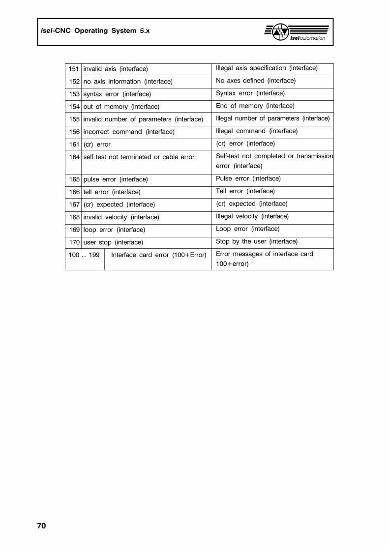
70
isel-CNC Operating System 5.x
151 invalid axis (interface)
152 no axis information (interface)
153 syntax error (interface)
154 out of memory (interface)
155 invalid number of parameters (interface)
156 incorrect command (interface)
161 (cr) error
164 self test not terminated or cable error
165 pulse error (interface)
166 tell error (interface)
167 (cr) expected (interface)
168 invalid velocity (interface)
169 loop error (interface)
170 user stop (interface)
100 ... 199 Interface card error (100+Error)
Illegal axis specification (interface)
No axes defined (interface)
Syntax error (interface)
End of memory (interface)
Illegal number of parameters (interface)
Illegal command (interface)
(cr) error (interface)
Self-test not completed or transmission
error (interface)
Pulse error (interface)
Tell error (interface)
(cr) expected (interface)
Illegal velocity (interface)
Loop error (interface)
Stop by the user (interface)
Error messages of interface card
100+error)