iseries engineering model sv - split system sheet water ... · model sv - split system ... air...
TRANSCRIPT

Engineering Submittal Sheet
Bosch Thermotechnology Corp. reserves the right to make changes without notice due to continuing engineering and technological advances | BTC 760208302 C | 03.2016
Bosch Thermotechnology Corp. Londonderry, NH • Ft. Lauderdale, FL
Tel: 1-866-642-3198 Fax: 1-954-776-5529 www.boschheatingandcooling.com
iSeries Model SV - Split System Water Source Heat Pump 1½ to 6 Ton
1 of 30
Standard Features, Factory Installed Options, and Field Installed Accessories
Standard Features for both Condenser Section and Air Handler/Fan Coil Section
SV Model 018 - 070 — 8 Models from 1 ½ through 6 tons — Cabinetry is constructed using heavy-gauge, galvanized
steel
Quiet Operation — All panels are insulated with ½" thick, 1.5 lb./cu.ft.
density micromat fiberglass insulation for both thermal insulation and noise reduction
Serviceability — All units are designed to be serviced from the front of
the unit
Refrigerant Circuit — Model SV Split Systems are designed using the optimum
combination of compressor, water and copper aluminum-fin evaporator coils with thermal expansion valves (TXV) to provide peak performance
Standard Warranty — 1-year Parts Limited Warranty — 5-year Compress or Limited Warranty
Standard Features for Condenser Section
Voltages — 208-230/1/60 — 277/1/60 — 208/3/60 — 460/3/60
Water Connections — All water connections are heavy duty bronze FPT
fittings securely fastened to the unit corner post
Coaxial Condenser Coil — Heavy duty copper coaxial condenser coil for
optimum heat transfer efficiencies
Overview and Certifi cations
Condenser Section
Compact Air Handler/Fan Coil

Bosch Thermotechnology Corp. reserves the right to make changes without notice due to continuing engineering and technological advances | BTC 760208302 C | 03.2016
Bosch Thermotechnology Corp.Londonderry, NH • Ft. Lauderdale, FL
Tel: 1-866-642-3198 Fax: 1-954-776-5529 www.boschheatingandcooling.com
Engineering Submittal Sheet
iSeries Model SV - Split System
Water Source Heat Pump 1½ to 6 Ton
2 of 30
Standard Features, Factory Installed Options, and Field Installed Accessories continued...
Filter Drier — Comes with the unit, it is field installed, protects unit
from air and other contamination from mixing with refrigerant and oil
Electronic circuit board/Unit Protection Module — Low and high pressure switch protection — Alarm output — Water coil/coaxial coil/condenser freeze protection — Anti-short cycling — 5 minute delay — Low pressure bypass at start up — Random unit start — Brown out protection
Optional Features for SV Condenser Section — 1/2" Closed Cell Foam Insullation — 1/2" Dual Density Insulation with Compressor Blanket — 1/2" Closed Cell Foam Insulation with
Compressor Blanket — Compressor Monitor Relay — 3-Phase Monitor — Pump/Valve Relay — Boilerless Control — Flow Proving Switch — 40 Amp External Disconnect Switch — Fire Alarm Relay — Wire for 208 Volt — Fault LED — 2 Way Solenoid Valve — Measure Flow Regulator (3 GPM/Ton) — 2 Way Solenoid & Measure Flow Regulator
Standard Features for Air Handler/Fan Coil Section
Air Handler/Fan Coil Transformer — Standard 50VA with manual rest feature
Unit Configurations — Horizontal or Vertical — Straight through air discharge horizontal
configuration only — End blow air discharge horizontal configuration only — Top blow air discharge vertical configuration only
Voltages — 208-230/1/60 — 277/1/60 — 460/3/60
Filter Rack — Unit comes standard with 1” Filter rack and
construction filter
Blower Motor — Constant Torque ECM Motor
Evaporator Coil — Cooper Hair Pins with Aluminum Fin evaporator coils
with factory installed TXV — 50VA Transformer
Filter Rack Hanging Brackets — All horizontal units come standard with hanging
bracket kits for suspending the unit from field supplied hanger rods
Optional Features for SV Air Handler/Fan Coil — Variable Speed Constant CFM ECM — DuoGuardTM Evaporator Coil — Closed Cell Foam Insulation — Energy Management Switch — 40 amp External Disconnect Switch — Wire for 208 Volts — MERV-8 filter w/ 4-Sided Filter Rack — MERV-13 filter w/ 4-Sided Filter Rack — 75, 100 VA Transformer

Bosch Thermotechnology Corp. reserves the right to make changes without notice due to continuing engineering and technological advances | BTC 760208302 C | 03.2016
Bosch Thermotechnology Corp.Londonderry, NH • Ft. Lauderdale, FL
Tel: 1-866-642-3198 Fax: 1-954-776-5529 www.boschheatingandcooling.com
Engineering Submittal Sheet
iSeries Model SV - Split System
Water Source Heat Pump 1½ to 6 Ton
3 of 30
Condenser Section Model Nomenclature
Fan Coil Model Nomenclature
MODEL:SV
NOMINAL CAPACITY:018, 024, 030, 036, 042, 048, 060, 070
VOLTAGE DESIGNATION:1 - 208-230/1/602 - 277/1/604 - 460/3/60
CABINET CONFIGURATION:VT - VerticalHZ - Horizontal
X - NA
X - NA
RETURN AIR CONFIGURATION:L - LeftR - Right
DISCHARGE AIR CONFIGURATION:T - TopS - StraightE - End
FAN/MOTOR OPTIONS:T - Constant Torque ECMA - Variable Speed Constant CFM ECM
AIR COIL OPTIONS:U - Uncoated Air CoilD - Duo Guard Air Coil
REVISION LEVEL:A - Current
AIR FILTRATION:1 - Standard Throwaway Filter w/ 2-Sided Filter Rack 1" 4 - MERV8 - 2" w/ 4-Sided Filter Rack 5 - MERV13 - 2" w/ 4-Sided Filter Rack
X - NA
X - NA
X - NA
X - NA
TRANSFORMER:5 - 50 VA7 - 75 VA STANDARD1 - 100 VA
X - NA
GENERAL ELECTRICAL OPTIONS (up to 5 available per unit): A - EMS relay J - Disconnect Switch M - Wire to 208 V X - As default for non used electrical codes
APPLICATION:T - TXV
CABINET CONSTRUCTION:A - Galvanized Steel / 1/2" Standard 1.5LB Dual Density Fiberglass C - Galvanized Steel / 1/2" Closed Cell Foam
X - NA
SV 018- 1 AV X X L T P U A X A G J X 5 X X X X 1
MODEL:SV
NOMINAL CAPACITY:018, 024, 030, 036, 042, 048, 060, 070
VOLTAGE DESIGNATION:1 - 208-230/1/602 - 277/1/603 - 208-230/3/604 - 460/3/60
CABINET CONFIGURATION:CS - Condensing Section
COAX OPTIONS:C - Copper N - Cupro-Nickel
WATER CONNECTIONS:F - Front
X - NA
X - NA
X - NA
X - NA
REVISION LEVEL:A - Current
X - NA
WATER FLOW CONTROL OPTIONS 2 - 2 Way Solenoid Valve 3 - MeasureFlow (3 GPM/Ton) 4 - 2 Way Solenoid + MeasureFlow
GENERAL ELECTRICAL OPTIONS (up to 5 available per unit) C - Compressor Monitor Relay D - Phase Monitor E - Pump/valve relay G - Boilerless control H - Flow proving switch J - Disconnect Switch K - Fire Alarm Relay/Dual Power T - Fault LED X - As default for non used electrical codes
X - NA
X - NA
STAND CONTROL
APPLICATION:G - EXTENDED RANGE (Geothermal)
X - NA
CABINET CONSTRUCTION:A - Galvanized Steel / 1/2" Standard 1.5LB Dual Density Fiberglass C - Galvanized Steel / 1/2" Closed Cell FoamD - Galvanized Steel / 1/2" Standard 1.5LB Dual Density Fiberglass, Extra Quiet F - Galvanized Steel 1/2" Closed Cell Foam,E xtra Quiet
SV 018- 1 CS C F X X X X A X A G X X X F X

Bosch Thermotechnology Corp. reserves the right to make changes without notice due to continuing engineering and technological advances | BTC 760208302 C | 03.2016
Bosch Thermotechnology Corp.Londonderry, NH • Ft. Lauderdale, FL
Tel: 1-866-642-3198 Fax: 1-954-776-5529 www.boschheatingandcooling.com
Engineering Submittal Sheet
iSeries Model SV - Split System
Water Source Heat Pump 1½ to 6 Ton
4 of 30
AHRI/ANSI 13256-1 Capacity and Effi ciency Data – Variable Speed Constant CFM ECM and Constant Torque ECM
Models
Water Loop Heat Pump Ground Loop Heat Pump
Cooling 86 °F Heating 68 °F Cooling 77 °F Heating 32 °F
Capacity (Btuh) EER (Btuh/W) Capacity (Btuh) COP Capacity (Btuh) EER (Btuh/W) Capacity (Btuh) COP
SV018 18,904 13.3 21,091 4.4 20,449 15.7 13,786 3.5
SV024 22,604 13.1 24,894 4.3 23,874 15.0 16,208 3.3
SV030 26,437 13.0 29,642 4.3 27,922 14.3 19,540 3.2
SV036 34,951 13.8 36,959 4.3 37,302 15.9 24,853 3.5
SV042 38,619 13.0 41,638 4.3 40,869 14.8 27,284 3.2
SV048 43,268 13.6 51,778 4.3 45,129 15.4 33,540 3.5
SV060 54,331 13.0 64,068 4.3 57,373 14.9 44,373 3.2
SV070 62,106 13.6 70,428 4.3 64,202 15.6 47,886 3.3
Ratings based upon AHRI/ANSI 13256-1 with 1" disposable fi lter.

Bosch Thermotechnology Corp. reserves the right to make changes without notice due to continuing engineering and technological advances | BTC 760208302 C | 03.2016
Bosch Thermotechnology Corp.Londonderry, NH • Ft. Lauderdale, FL
Tel: 1-866-642-3198 Fax: 1-954-776-5529 www.boschheatingandcooling.com
Engineering Submittal Sheet
iSeries Model SV - Split System
Water Source Heat Pump 1½ to 6 Ton
5 of 30
Units (024 & 030) with -4 voltage (460/1/60), the X13 motor will be 1/2 HP rather than 1/3 HP.
Factory Charge is based on 25 ft of lineset with linset diameter according to table. Charge adjustments will need to be made for linesets of differing length and/or diameters. Additional charge must also be added for factory supplied fi lter drier. All charge rates MUST ALWAYS be confi rmed and adjusted if necessary by subcooling and superheat measurements (even with a 25 ft lineset and default factory charge). See section on charging according to subcooling and superheat.
Condenser Section Physical Data
Description SV018 SV024 SV030 SV036 SV042 SV048 SV060 SV070
Compressor Type (Qty 1) Reciprocating Reciprocating Reciprocating Reciprocating Reciprocating Scroll Scroll Scroll
Factory Charge, R410A (oz)** 40 44 52 61 58 59 93 90
Liquid Line Sweat Connection (in) 3/8 3/8 3/8 3/8 3/8 3/8 3/8 3/8
Suction Line Sweat Connection (in) 3/4 3/4 3/4 3/4 3/4 3/4 7/8 7/8
Water Connection Size
Water Connection Size, FPT 3/4 3/4 3/4 3/4 3/4 1 1 1
Coaxial Coil Volume (gal) 0.14 0.14 0.24 0.27 0.27 0.49 0.62 0.62
Max Water Working Pressure (PSIG) 400 400 400 400 400 400 400 400
Cabinet
Weight - Operating (lbs) 99 102 110 125 130 167 171 178
Weight - Shipping (lbs) 127 130 137 151 156 192 195 202
Fan Coil Physical Data
Description SV018 SV024 SV030 SV036 SV042 SV048 SV060 SV070
Condensate Connection Size, FPT 3/4 3/4 3/4 3/4 3/4 3/4 3/4 3/4
Liquid Line Sweat Connection (in) 3/8 3/8 3/8 3/8 3/8 3/8 3/8 3/8
Suction Line Sweat Connection (in) 1/2 5/8 5/8 3/4 3/4 3/4 7/8 7/8
ECM Fan Motor & Blower
Fan Motor Type/Speeds ECM Const Air Flow
ECM Const Air Flow
ECM Const Air Flow
ECM Const Air Flow
ECM Const Air Flow
ECM Const Air Flow
ECM Const Air Flow
ECM Const Air Flow
Fan Motor (HP) 1/3 1/3 / 1/2* 1/3 / 1/2* 1/2 3/4 3/4 1 1
Blower Wheel Size (Dia. x W) 9x7 9x7 9x7 9x7 10x8 10x8 11x9 11x9
Vertical Cabinet (AV)
Air Coil Dimensions (H x W) 16x16.5 20x16.5 20x16.5 24x20.2 24x20.2 24x26.75 24x26.75 32x26.2
Standard Filter - 1" Throwaway (L x H) 16x20 20x20 20x20 24x24 24x24 24x30 24x30 16x30 @2
Optional Filter - 2" MERV-8 or 13 Throwaway (L x H) 16x20 20x20 20x20 24x24 24x24 24x30 24x30 16x30 @2
Weight - Operating (lbs) 70 72 76 96 107 123 140 158
Weight - Shipping (lbs) 98 100 103 122 134 148 164 182
Horizontal Air Handler
Air Coil Dimensions (H x W) 16x16.5 16x20.5 16x20.5 18x27.5 18x27.5 20x32 20x32 20x42
Standard Filter - 1" Throwaway (L x H) 16x20 16x25 16x25 18x30 18x30 20x34.5 20x34.5 20x24 @2
Optional Filter - 2" MERV-8 or 13 Throwaway (L x H) 16x20 16x25 16x25 18x30 18x30 20x34.5 20x34.5 20x24 @2
Weight - Operating (lbs) 71 76 76 93 100 110 121 138
Weight - Shipping (lbs) 105 107 110 138 133 135 151 187

Bosch Thermotechnology Corp. reserves the right to make changes without notice due to continuing engineering and technological advances | BTC 760208302 C | 03.2016
Bosch Thermotechnology Corp.Londonderry, NH • Ft. Lauderdale, FL
Tel: 1-866-642-3198 Fax: 1-954-776-5529 www.boschheatingandcooling.com
Engineering Submittal Sheet
iSeries Model SV - Split System
Water Source Heat Pump 1½ to 6 Ton
6 of 30
Operating Limits - Cooling & Heating
Description Extended Range Option
COOLING
Minimum ambient air temperature 50
Maximum ambient air temperature 100
Minimum evaporator entering air db/wb °F 68/57
Rated air coil entering air db/wb °F 80/67
Maximum evaporator entering air db/wb °F 95/85
Minimum water coil entering fl uid temperature °F 50
Water loop typical coil entering fl uid range temperature °F 70/90
Maximum water coil entering fl uid temperature °F 110
HEATING
Minimum ambient air temperature °F 40
Maximum ambient air temperature °F 85
Minimum evaporator entering air db °F 50
Rated air coil entering air °F 68
Maximum evaporator entering air db °F 80
Normal water coil entering fl uid range °F 25-80
Minimum water coil entering Fluid °F 20* * antifreeze solution is required at these fl uid temperatures.
Bosch Thermotechnology Corp. reserves the right to make changes without notice due to continuing engineering and technological advances | BTC 760208302 C | 03.2016
Bosch Thermotechnology Corp.Londonderry, NH • Ft. Lauderdale, FL
Tel: 1-866-642-3198 Fax: 1-954-776-5529 www.boschheatingandcooling.com
Engineering Submittal Sheet
iSeries Model SV - Split System
Water Source Heat Pump 1½ to 6 Ton
7 of 30
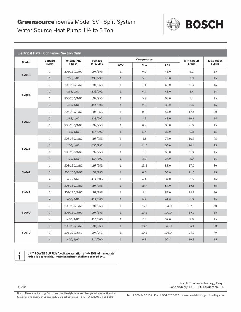
Electrical Data - Condenser Section Only
Model Voltage Code
Voltage/Hz/Phase
Voltage Min/Max
Compressor Min Circuit Amps
Max Fuse/ HACRQTY RLA LRA
SV0181 208-230/1/60 197/253 1 6.5 43.0 8.1 15
2 265/1/60 238/292 1 5.8 46.0 7.3 15
SV024
1 208-230/1/60 197/253 1 7.4 43.0 9.3 15
2 265/1/60 238/292 1 6.7 46.0 8.4 15
3 208-230/3/60 197/253 1 5.9 63.0 7.4 15
4 460/3/60 414/506 1 2.9 30.0 3.6 15
SV030
1 208-230/1/60 197/253 1 9.9 54.0 12.4 20
2 265/1/60 238/292 1 8.5 46.0 10.6 15
3 208-230/3/60 197/253 1 6.9 63.0 8.6 15
4 460/3/60 414/506 1 5.4 30.0 6.8 15
SV036
1 208-230/1/60 197/253 1 13 74.0 16.3 25
2 265/1/60 238/292 1 11.3 67.0 14.1 25
3 208-230/3/60 197/253 1 7.8 68.0 9.8 15
4 460/3/60 414/506 1 3.9 34.0 4.9 15
SV042
1 208-230/1/60 197/253 1 13.6 88.0 17.0 30
3 208-230/3/60 197/253 1 8.8 68.0 11.0 15
4 460/3/60 414/506 1 4.4 34.0 5.5 15
SV048
1 208-230/1/60 197/253 1 15.7 84.0 19.6 35
3 208-230/3/60 197/253 1 11 88.0 13.8 20
4 460/3/60 414/506 1 5.4 44.0 6.8 15
SV060
1 208-230/1/60 197/253 1 26.3 134.0 32.9 50
3 208-230/3/60 197/253 1 15.6 110.0 19.5 35
4 460/3/60 414/506 1 7.8 52.0 9.8 15
SV070
1 208-230/1/60 197/253 1 28.3 178.0 35.4 60
3 208-230/3/60 197/253 1 19.2 136.0 24.0 40
4 460/3/60 414/506 1 8.7 66.1 10.9 15
UNIT POWER SUPPLY: A voltage variation of +/- 10% of nameplate rating is acceptable. Phase imbalance shall not exceed 2%.

Bosch Thermotechnology Corp. reserves the right to make changes without notice due to continuing engineering and technological advances | BTC 760208302 C | 03.2016
Bosch Thermotechnology Corp.Londonderry, NH • Ft. Lauderdale, FL
Tel: 1-866-642-3198 Fax: 1-954-776-5529 www.boschheatingandcooling.com
Engineering Submittal Sheet
iSeries Model SV - Split System
Water Source Heat Pump 1½ to 6 Ton
8 of 30
Electrical Data - Air Handler/Fan Coil Section with Variable Speed Constant CFM ECM
Model Voltage Code Voltage/Hz/Phase Voltage Min/MaxBlower Motor
Min Circuit Amps Max Fuse/ HACRFLA HP
SV018
1 208-230/1/60 197/253 2.8 0.30 3.5 15
2 265/1/60 238/292 2.6 0.30 3.3 15
SV024
1 208-230/1/60 197/253 2.8 0.30 3.5 15
2 265/1/60 238/292 2.6 0.30 3.3 15
4 460/3/60 414/506 2.6 0.30 3.3 15
SV030
1 208-230/1/60 197/253 2.8 0.30 3.5 15
2 265/1/60 238/292 2.6 0.30 3.3 15
4 460/3/60 414/506 2.6 0.30 3.3 15
SV036
1 208-230/1/60 197/253 4.3 0.5 5.4 15
2 265/1/60 238/292 4.1 0.5 5.1 15
4 460/3/60 414/506 4.1 0.5 5.1 15
SV042
1 208-230/1/60 197/253 6.8 0.8 8.5 15
4 460/3/60 414/506 5.5 0.8 6.9 15
SV048
1 208-230/1/60 197/253 6.8 0.80 8.5 15
4 460/3/60 414/506 5.5 0.80 6.9 15
SV060
1 208-230/1/60 197/253 9.1 1.00 11.4 20
4 460/3/60 414/506 6.9 1.00 8.6 15
SV070
1 208-230/1/60 197/253 9.1 1.00 11.4 20
4 460/3/60 414/506 6.9 1.00 8.6 15
208/230V units shipped with transformer wired for 230V—for 208V remove orange tranformer primary lead and replace with red lead. All blower motors are single phase. 460/3/60 units with variable speed constant CFM ECM has a 460V single phase ECM and requires one line, one neutral, and one ground wire.

Bosch Thermotechnology Corp. reserves the right to make changes without notice due to continuing engineering and technological advances | BTC 760208302 C | 03.2016
Bosch Thermotechnology Corp.Londonderry, NH • Ft. Lauderdale, FL
Tel: 1-866-642-3198 Fax: 1-954-776-5529 www.boschheatingandcooling.com
Engineering Submittal Sheet
iSeries Model SV - Split System
Water Source Heat Pump 1½ to 6 Ton
9 of 30
Electrical Data - Air Handler/Fan Coil Section with Constant Torque ECM
Model Voltage Code Voltage/Hz/Phase Voltage Min/MaxBlower Motor
Min Circuit Amps Max Fuse/ HACRFLA HP
SV018
1 208-230/1/60 197/253 2.8 0.30 3.5 15
2 265/1/60 238/292 2.6 0.30 3.3 15
SV024
1 208-230/1/60 197/253 2.8 0.30 3.5 15
2 265/1/60 238/292 2.6 0.30 3.3 15
4 460/3/60 414/506 2.1 0.50 2.6 15
SV030
1 208-230/1/60 197/253 2.8 0.30 3.5 15
2 265/1/60 238/292 2.6 0.30 3.3 15
4 460/3/60 414/506 2.1 0.50 2.6 15
SV036
1 208-230/1/60 197/253 4.1 0.5 5.1 15
2 265/1/60 238/292 3.9 0.5 4.9 15
4 460/3/60 414/506 2.1 0.5 2.6 15
SV042
1 208-230/1/60 197/253 6.0 0.8 7.5 15
4 460/3/60 414/506 4.6 0.8 5.8 15
SV048
1 208-230/1/60 197/253 6.0 0.80 7.5 15
4 460/3/60 414/506 4.6 0.80 5.8 15
SV060
1 208-230/1/60 197/253 7.6 1.00 9.5 15
4 460/3/60 414/506 4.0 1.00 5.0 15
SV070
1 208-230/1/60 197/253 7.6 1.00 9.5 15
4 460/3/60 414/506 4.0 1.00 5.0 15
208/230V units shipped with transformer wired for 230V—for 208V
remove orange tranformer primary lead and replace with red lead. All blower motors are single phase. 460/3/60 units with a constant torque ECM has a 460V single phase ECM and requires two power and one ground wire.

Bosch Thermotechnology Corp. reserves the right to make changes without notice due to continuing engineering and technological advances | BTC 760208302 C | 03.2016
Bosch Thermotechnology Corp.Londonderry, NH • Ft. Lauderdale, FL
Tel: 1-866-642-3198 Fax: 1-954-776-5529 www.boschheatingandcooling.com
Engineering Submittal Sheet
iSeries Model SV - Split System
Water Source Heat Pump 1½ to 6 Ton
10 of 30
Blower Performance Constant Torque ECM
Model Fan Speed
Rated Airfl ow
(Motor tap will vary)
Available External Static Pressure (in. wc. Wet coil and fi lter included)
0.10 0.20 0.30 0.40 0.50 0.60 0.70 0.80 0.90 1.00 1.10 1.20
SV018
1
650
630 590 560 530 490 - - - - - - -
2 720 700 670 630 600 560 - - - - - -
3 790 770 750 710 670 620 560 - - - - -
4 910 890 850 810 740 670 590 520 - - - -
5 1010 970 920 860 810 750 660 530 - - - -
SV024
1
850
650 610 580 560 520 - - - - - - -
2 740 720 690 660 620 570 - - - - - -
3 850 830 800 770 730 690 630 - - - - -
4 950 920 890 870 840 820 770 650 - - - -
5 1160 1110 1050 990 920 800 670 560 - - - -
SV030
1
950
620 600 570 540 490 - - - - - - -
2 730 710 670 640 610 550 - - - - - -
3 820 790 760 740 710 670 630 - - - - -
4 940 910 880 850 800 740 660 - - - - -
5 1070 1010 950 900 840 760 670 - - - - -
SV036
1
1200
1120 1090 1055 1030 1000 - - - - - - -
2 1260 1230 1200 1170 1140 1080 - - - - - -
3 1330 1293 1253 1210 1167 1100 1030 - - - - -
4 1400 1357 1307 1250 1193 1120 1040 963 - - - -
5 1470 1420 1360 1290 1220 1140 1050 970 890 - - -
SV042
1
1400
1270 1250 1230 1210 - - - - - - - -
2 1440 1420 1410 1410 1400 1380 1340 - - - - -
3 1540 1530 1510 1500 1490 1470 1430 1350 - - - -
4 1650 1630 1610 1600 1580 1530 1460 1360 1240 - - -
5 1730 1720 1700 1670 1620 1570 1490 1380 1260 1100 - -
SV048
1
1600
1390 1370 1350 1320 - - - - - - - -
2 1600 1580 1550 1530 1510 - - - - - - -
3 1730 1700 1670 1650 1630 1600 1580 1540 - - - -
4 1830 1810 1780 1760 1740 1710 1670 1600 1520 - - -
5 1930 1910 1880 1860 1830 1780 1720 1640 1540 1420 - -
SV060
1
2000
1900 1880 1860 1820 - - - - - - - -
2 2000 1970 1950 1920 1890 1860 - - - - - -
3 2110 2090 2060 2030 2010 1970 1940 1910 1880 - - -
4 2220 2200 2170 2140 2110 2080 2050 2060 2050 2000 1920 -
5 2340 2320 2290 2260 2230 2210 2180 2150 2110 2070 2000 1930
SV070
1
2100
2050 2010 1970 1930 - - - - - - - -
2 2150 2120 2080 2030 1990 1960 - - - - - -
3 2270 2230 2200 2160 2120 2080 2040 2010 1980 - - -
4 2390 2350 2320 2280 2250 2200 2160 2130 2100 2070 2030 -
5 2520 2480 2450 2420 2380 2330 2290 2260 2220 2170 2100 2020
Note: Air fl ow is 70% of tabulated values during fan only operation.
Air fl ow is 85% of tabulated value during passive dehumidfi cation mode when enabled.

Bosch Thermotechnology Corp. reserves the right to make changes without notice due to continuing engineering and technological advances | BTC 760208302 C | 03.2016
Bosch Thermotechnology Corp.Londonderry, NH • Ft. Lauderdale, FL
Tel: 1-866-642-3198 Fax: 1-954-776-5529 www.boschheatingandcooling.com
Engineering Submittal Sheet
iSeries Model SV - Split System
Water Source Heat Pump 1½ to 6 Ton
11 of 30
Blower Performance Variable Speed Constant CFM ECM
Model Rated Airfl ow Tap Adjust
SettingsFan Only
Available External Static Pressure (in. wc. Wet coil and fi lter included
0.10 0.20 0.30 0.40 0.50 0.60 0.70 0.80 0.90 1.00 1.10 1.20
SV018 650 B
- 550 540 540 540 540 540 540 530 520 500 - - -
Norm 650 650 650 650 650 650 640 630 610 590 - - -
+ 750 750 750 750 750 750 740 730 710 690 - - -
SV024 850 C
- 720 720 720 720 720 720 720 700 650 560 - - -
Norm 850 850 850 850 850 850 850 850 800 700 - - -
+ 960 960 960 960 960 960 960 960 880 790 - - -
SV030 950 D
- 810 810 810 810 810 810 810 770 720 650 - - -
Norm 950 950 950 950 950 950 950 900 850 780 - - -
+ 980 980 980 980 980 980 980 950 900 820 - - -
SV036 1200 A
- 1020 1020 1020 1020 1020 1020 1000 990 960 930 - - -
Norm 1200 1200 1200 1200 1200 1200 1180 1160 1130 1090 - - -
+ 1380 1380 1380 1380 1380 1380 1360 1330 1300 1250 - - -
SV042 1400 B
- 1190 1190 1190 1190 1190 1190 1190 1190 1190 1190 1190 - -
Norm 1400 1400 1400 1400 1400 1400 1400 1400 1400 1400 1400 - -
+ 1630 1630 1630 1630 1630 1630 1630 1630 1630 1630 1630 - -
SV048 1600 A
- 1340 1340 1340 1340 1340 1340 1340 1340 1340 1340 1340 - -
Norm 1600 1600 1600 1600 1600 1600 1600 1600 1600 1600 1600 - -
+ 1810 1810 1810 1810 1810 1810 1810 1810 1810 1810 1810 - -
SV060 2000 A
- 1700 1700 1700 1700 1700 1700 1700 1700 1700 1690 1690 1680 -
Norm 2000 2000 2000 2000 2000 2000 2000 2000 2000 1980 1980 1980 -
+ 2220 2220 2220 2220 2220 2220 2220 2220 2220 2130 2100 2070 -
SV070 2200 B
- 1870 1870 1870 1870 1870 1870 1870 1870 1870 1870 1870 1870 -
Norm 2200 2200 2200 2200 2200 2200 2200 2200 2200 2200 2200 2200 -
+ 2330 2330 2330 2330 2330 2330 2330 2330 2330 2330 2330 2330 -
Note: Air fl ow is 70% of tabulated values during fan only operation.

Bosch Thermotechnology Corp. reserves the right to make changes without notice due to continuing engineering and technological advances | BTC 760208302 C | 03.2016
Bosch Thermotechnology Corp.Londonderry, NH • Ft. Lauderdale, FL
Tel: 1-866-642-3198 Fax: 1-954-776-5529 www.boschheatingandcooling.com
Engineering Submittal Sheet
iSeries Model SV - Split System
Water Source Heat Pump 1½ to 6 Ton
12 of 30
Horizontal Cabinet Corner Weights
Confi guration Left Hand Evaporator Right Hand Evaporator
Model Unit Total Left Front* Right Front* Left Back Right Back Left Front* Right Front* Left Back Right Back
SV018
71 14 12 20 25 12 14 25 20 48
32 6 5 9 11 5 6 11 9 22
SV024
76 16 13 21 27 13 16 27 21 48
34 7 6 10 12 6 7 12 10 22
SV030
76 16 12 21 28 12 16 28 21 52
34 7 5 10 13 5 7 13 10 23
SV036
93 19 14 25 35 14 19 35 25 66
42 9 6 11 16 6 9 16 11 30
SV042
100 21 15 27 37 15 21 37 27 64
45 10 7 12 17 7 10 17 12 29
SV048
110 22 18 33 36 18 22 36 33 62
50 10 8 15 16 8 10 16 15 28
SV060
121 26 19 34 42 19 26 42 34 69
55 12 9 15 19 9 12 19 15 31
SV070
138 30 22 38 48 22 30 48 38 76
63 14 10 17 22 10 14 22 17 35
* Front is control box end

Bosch Thermotechnology Corp. reserves the right to make changes without notice due to continuing engineering and technological advances | BTC 760208302 C | 03.2016
Bosch Thermotechnology Corp.Londonderry, NH • Ft. Lauderdale, FL
Tel: 1-866-642-3198 Fax: 1-954-776-5529 www.boschheatingandcooling.com
Engineering Submittal Sheet
iSeries Model SV - Split System
Water Source Heat Pump 1½ to 6 Ton
13 of 30
Refrigerant Charge, General Line Sizing and Capacity Mulitplier1
Model Factory R410A Charge (oz)2
Refrigerant Line O.D. Size (Based on Equivalent Line Length)3
Suct. Line Riser Max.425 FT2 35 FT 50 FT 75 FT
LIQ. SUC. LIQ. SUC. LIQ. SUC. LIQ. SUC.
SV018 40 3/8 5/8 3/8 5/8 3/8 5/8 3/8 3/4 5/8
SV024 40 3/8 5/8 3/8 5/8 3/8 3/4 3/8 7/8 5/8
SV030 48 3/8 3/4 3/8 3/4 3/8 3/4 3/8 7/8 3/4
SV036 61 3/8 3/4 3/8 3/4 3/8 7/8 3/8 7/8 3/4
SV042 58 3/8 3/4 3/8 3/4 3/8 7/8 3/8 7/8 7/8
SV048 59 3/8 3/4 3/8 7/8 3/8 7/8 3/8 1-1/8 7/8
SV060 79 3/8 7/8 1/2 7/8 1/2 1-1/8 1/2 1-1/8 7/8
SV070 76 3/8 7/8 1/2 1-1/8 1/2 1-1/8 1/2 1-1/8 7/8
Capacity Multiplier 1.00 0.995 0.990 0.980
Example 1: Model SV036 with 45ft of equivalent length of 3/8” O.D Liquid Line and factory supplied fi lter drier 860-006. Estimated Total System Charge = Factory charge +/- (45ft - 25 ft) x .60 oz/ft + fi lter drier adjustment. Estimated Total System Charge = 61 oz + (20ft x .60 oz/ft) + 11 oz = 84 oz. Estimate an additional 23 oz of R410A refrigerant is required. After adding estimated additional charge, adjust fi nal charge according to subcooling and superheat measurements. See section on charging according to subcooling and superheat. Example 2: Model SV060 with 10ft of equivalent length of 3/8” O.D Liquid Line and factory supplied fi lter drier 860-006. Total system charge= Factory charge +/- (25ft - 10ft) x .60 oz/ft + fi lter drier adjustment. Total System Charge = 79 oz - (15ft x .60 oz/ft) + 11 oz = 81 oz. Add 2 oz of R410A refrigerant. After adding estimated additional charge, adjust fi nal charge according to subcooling and superheat measurements. See section on charging according to subcooling and superheat.
Example 3: Model SV030 with 25ft of equivalent length of 3/8” O.D Liquid Line and factory supplied fi lter drier 860-005. Total system charge = Factory charge + adjustment for larger liquid line diameter + fi lter drier adjustment. Total System Charge = 48 oz - (25ft x .44 oz/ft) + (25ft x .60 oz/ft) + 8 oz = 60 oz. Add 12 oz of R410A refrigerant. After adding estimated additional charge, adjust fi nal charge according to subcooling and superheat measurements. See section on charging according to subcooling and superheat.
Note: 1. Liquid and suction line sizes should be sized according to table, not according to king valve connection size.
Note: 2. Factory Charge is based on 25 ft of lineset with linset diameter according to table. Charge adjustments will need to be made for linesets of differing length and/or diameters. Additional charge must also be added for factory supplied fi lter drier. All char-ge rates MUST ALWAYS be confi rmed and adjusted if necessary by subcooling and superheat measurements (even with a 25 ft lineset and default factory charge). See section on charging according to subcooling and superheat.
Note: 3. Next diameter size up should be used if equivalent length is longer than shown (75 ft is max).
Note: 4. Suction line max riser diameter is typically sized to meet minimum of 1,250 FPM refrigerant velocity for proper oil return.
Note: 5. With 1/2" liquid lines it is recommended to place units as close as practical (minimizing the increased refrigerant volume imposed by the larger line) for maximum compressor life.
Bosch Thermotechnology Corp. reserves the right to make changes without notice due to continuing engineering and technological advances | BTC 760208302 C | 03.2016
Bosch Thermotechnology Corp.Londonderry, NH • Ft. Lauderdale, FL
Tel: 1-866-642-3198 Fax: 1-954-776-5529 www.boschheatingandcooling.com
Engineering Submittal Sheet
iSeries Model SV - Split System
Water Source Heat Pump 1½ to 6 Ton
14 of 30
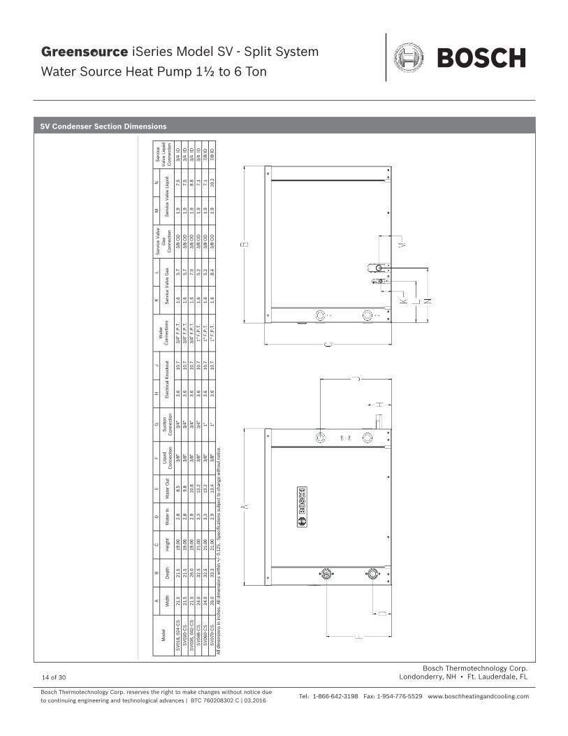
SV Condenser Section Dimensions
A
B
C
DE
FG
HJ
KL
MN
Wid
thD
epth
Hei
ght
Wat
er In
Wat
er O
utLi
quid
C
onne
ctio
nS
uctio
n C
onne
ctio
n
SV
018,
024
-CS
21.5
21.5
19.0
02.
88.
53/
8"
3/4"
3.
610
.73/
4" F
.P.T
.1.
65.
73/
8 O
D1.
97.
53/
4 ID
SV
030-
CS
21.5
21.5
19.0
02.
89.
83/
8"
3/4"
3.
610
.73/
4" F
.P.T
.1.
65.
73/
8 O
D1.
97.
53/
4 ID
SV
036,
042
-CS
21.5
26.0
19.0
02.
810
.83/
8"3/
4"
3.6
10.7
3/4"
F.P
.T.
1.6
7.0
3/8
OD
1.9
8.8
3/4
IDS
V04
8-C
S24
.032
.521
.00
3.3
13.2
3/8"
3/
4"
3.6
10.7
1" F
.P.T
.1.
65.
23/
8 O
D1.
97.
13/
4 ID
SV
060-
CS
24.0
32.5
21.0
03.
313
.23/
8"
1"
3.6
10.7
1" F
.P.T
.1.
65.
23/
8 O
D1.
97.
17/
8 ID
SV
070-
CS
26.0
33.3
21.0
02.
913
.43/
8"
1"
3.6
10.7
1" F
.P.T
.1.
68.
43/
8 O
D1.
910
.27/
8 ID
All
dim
ensi
ons
in in
ches
. All
dim
ensi
ons
with
in +
/- 0.
125.
Spe
cific
atio
ns s
ubje
ct to
cha
nge
with
out n
otic
e.
Mod
elW
ater
C
onne
ctio
ns
Ser
vice
Val
ve
Gas
C
onne
ctio
n
Ser
vice
V
alve
Liq
uid
Con
nect
ion
Ele
ctric
al K
nock
out
Ser
vice
Val
ve G
asS
ervi
ce V
alve
Liq
uid

Bosch Thermotechnology Corp. reserves the right to make changes without notice due to continuing engineering and technological advances | BTC 760208302 C | 03.2016
Bosch Thermotechnology Corp.Londonderry, NH • Ft. Lauderdale, FL
Tel: 1-866-642-3198 Fax: 1-954-776-5529 www.boschheatingandcooling.com
Engineering Submittal Sheet
iSeries Model SV - Split System
Water Source Heat Pump 1½ to 6 Ton
15 of 30
SV Vertical Air Handler DimensionsA
BC
DE
FG
HJ
KL
MN
P
Wid
thD
epth
Hei
ght
Dis
char
geD
epth
Dis
char
geW
idth
Cabi
net
Fron
t to
Dis
char
ge
Side
to
Dis
char
ge
Bott
om to
Co
nden
sate
D
rain
Side
to
Cond
ensa
teFr
ont t
o R/
ABo
ttom
to
Dis
char
geR/
A D
uct
Wid
th
R/A
Duc
t Fl
ange
H
eigh
t
Filte
r Ra
ck
Hei
ght
SV01
821
.521
.521
.62
14.0
14.0
4.5
5.2
1.0
4.4
1.8
1.6
18.0
18.0
16.0
3/4"
F.P
.T.
20x2
0x1
SV02
421
.521
.521
.62
14.0
14.0
4.5
5.2
1.0
4.4
1.8
1.6
18.0
18.0
20.0
3/4"
F.P
.T.
20x2
0x1
SV03
021
.521
.521
.62
14.0
14.0
4.5
5.2
1.0
4.4
1.8
1.6
18.0
18.0
20.0
3/4"
F.P
.T.
20x2
0x1
SV03
621
.526
.025
.62
16.0
14.0
6.2
5.0
1.0
4.4
2.0
1.6
22.0
22.0
24.0
3/4"
F.P
.T.
24x2
4x1
SV04
221
.526
.025
.62
16.0
14.0
6.2
5.0
1.0
4.4
2.0
1.6
22.0
22.0
24.0
3/4"
F.P
.T.
24x2
4x1
SV04
824
.032
.525
.62
18.0
14.0
7.5
6.2
1.0
4.4
2.3
1.6
28.0
22.0
24.0
3/4"
F.P
.T.
24x3
0x1
SV06
024
.032
.525
.62
18.0
14.0
7.5
6.2
1.0
4.4
2.3
1.6
28.0
22.0
24.0
3/4"
F.P
.T.
24x3
0x1
SV07
033
.326
.033
.62
18.0
16.0
7.5
7.2
1.0
4.4
2.6
1.6
28.0
30.0
32.0
3/4"
F.P
.T.
16x3
0x1
(2)
All
dim
ensi
ons
in in
ches
. All
dim
ensi
ons
with
in +
/- 0
.125
. Sp
ecifi
catio
ns s
ubje
ct to
cha
nge
with
out n
otic
e. 1
" filte
r rac
k ex
tend
s 1.
23" b
eyon
d th
e si
de o
f the
uni
t. 2
" filte
r rac
k ex
tend
s 2.
89 "
beyo
nd th
e si
de o
f the
uni
t. 2
" filte
r rac
k le
ngth
is .2
" lon
ger,
leng
then
ing
dim
M b
y .2
"Th
e 2"
filte
r rac
k is
4 s
ided
with
a fi
lter a
cces
s do
or o
n ea
ch e
nd a
nd c
an a
ccep
t eith
er a
1" o
r 2" fi
lter
Refr
iger
ant l
ine
conn
ectio
ns a
re lo
cate
d in
bac
k co
rner
. Fi
eld
pipi
ng c
an b
e br
ough
t in
thro
ugh
knoc
kout
s lo
cate
d in
fron
t or b
ack
corn
er.
On
units
018
, 024
, 030
the
left
han
d co
nfigu
ratio
n co
mes
with
the
e-bo
x in
the
back
of t
he u
nit b
ut c
an b
e ac
cess
ed th
roug
h th
e fr
ont.
Mod
elCo
nden
sate
D
rain
Co
nnec
tion
Reco
mm
ende
d Re
plac
emen
t N
omin
al F
ilter
Si
ze

Bosch Thermotechnology Corp. reserves the right to make changes without notice due to continuing engineering and technological advances | BTC 760208302 C | 03.2016
Bosch Thermotechnology Corp.Londonderry, NH • Ft. Lauderdale, FL
Tel: 1-866-642-3198 Fax: 1-954-776-5529 www.boschheatingandcooling.com
Engineering Submittal Sheet
iSeries Model SV - Split System
Water Source Heat Pump 1½ to 6 Ton
16 of 30
AB
CD
EF
JK
MN
PQ
RT
Wid
thD
epth
Hei
ght
Cab
inet
E
nd to
F
ilter
R
ack
R/A
Duc
t W
idth
Cab
F
ront
to
Filt
er
Rac
k
Sid
e to
D
isch
arge
(E
nd)
Dis
char
geW
idth
Top
to
Dis
char
ge
(FLE
&
FR
S)
Dis
char
geH
eigh
t
End
to
Dis
char
ge
(Str
aigh
t)
Top
to
Dis
char
ge
(FR
E &
FLS
)
Filt
er
Rac
k H
eigh
t
R/A
Duc
t F
lang
e H
eigh
t
SV
018
22.0
43.0
17.0
1.5
20.1
521
.35
5.42
9.13
6.11
9.65
4.92
1.23
16.3
14.5
3/4"
FP
T16
× 2
0 ×
1
SV
024
22.0
43.0
17.0
1.5
25.0
16.5
5.42
9.13
6.11
9.65
4.92
1.23
16.3
14.5
3/4"
FP
T16
× 2
5 ×
1
SV
030
22.0
43.0
17.0
1.5
25.0
16.5
5.42
9.13
6.11
9.65
4.92
1.23
16.3
14.5
3/4"
FP
T16
× 2
5 ×
1
SV
036
22.0
54.5
19.0
1.5
30.1
522
.85
6.47
9.13
7.5
10.2
85.
971.
2118
.316
.53/
4" F
PT
18 ×
30
× 1
SV
042
22.0
54.5
19.0
1.5
30.1
522
.85
5.27
10.4
56.
4611
.34.
771.
2218
.316
.53/
4" F
PT
18 ×
30
× 1
SV
048
25.0
54.5
21.0
1.5
34.6
18.4
7.25
10.4
57.
4611
.36
6.75
2.16
20.3
18.5
3/4"
FP
T20
× 3
4.5
× 1
SV
060
25.0
54.5
21.0
1.5
34.6
18.4
6.32
11.7
66.
8112
.55.
821.
6820
.318
.53/
4" F
PT
20 ×
34.
5 ×
1
SV
070
25.0
65.0
21.0
1.5
48.1
15.4
6.32
11.7
66.
8112
.55.
821.
6820
.318
.53/
4" F
PT
20 ×
24
× 1
(2)
All
dim
ensi
ons
in in
ches
. All
dim
ensi
ons
with
in +
/- 0.
125.
Spe
cific
atio
ns s
ubje
ct to
cha
nge
with
out n
otic
e. 1
" filt
er r
ack
exte
nds
1.23
" bey
ond
the
side
of t
he u
nit.
2" f
ilter
rac
k ex
tend
s 2.
89 "
beyo
nd th
e si
de o
f the
uni
t. 2
" filt
er ra
ck le
ngth
is .2
" lon
ger,
leng
then
ing
dim
M b
y .2
"Th
e 2"
filte
r ra
ck is
4 s
ided
with
a fi
lter
acce
ss d
oor
on e
ach
end
and
can
acce
pt e
ither
a 1
" or
2" fi
lter
Ref
riger
ant l
ine
conn
ectio
ns a
re lo
cate
d di
rect
ly b
ehin
d re
frig
eran
t lin
e kn
ocko
uts.
Mod
elC
onde
nsat
e D
rain
C
onne
ctio
n
Rec
omm
ende
d R
epla
cem
ent
Nom
inal
Filt
er
Siz
e SV Horizontal Air Handler Dimensions

Bosch Thermotechnology Corp. reserves the right to make changes without notice due to continuing engineering and technological advances | BTC 760208302 C | 03.2016
Bosch Thermotechnology Corp.Londonderry, NH • Ft. Lauderdale, FL
Tel: 1-866-642-3198 Fax: 1-954-776-5529 www.boschheatingandcooling.com
Engineering Submittal Sheet
iSeries Model SV - Split System
Water Source Heat Pump 1½ to 6 Ton
17 of 30
COOLING HEATINGEntering
Fluid Temp (F)
Water Flow (GPM)
Pressure Drop PSI
(FOH)
Entering Air Temp (db/
wb) F
Total Capacity (MBTUH)
Sensible Capacity (MBTUH)
Heat of Rejection (MBTUH)
Power Input (kW) EER
Entering Fluid Temp
(F)
Pressure Drop PSI
(FOH)
Entering Air Temp (F)
Total Capacity (MBTUH)
Heat of Absorption (MBTUH)
Power Input (kW) COP
50
2.5 1.2 (2.8)75/63 21.3 15.9 24.6 1.1 18.6
30*
1.4 (3.2)60 11.0 8.2 1.0 3.2
80/67 22.9 16.6 26.4 1.2 19.9 70 10.4 7.5 1.0 2.985/71 24.7 17.2 28.2 1.2 21.4 80 9.7 6.8 1.1 2.7
4 2.9 (6.6)75/63 22.3 16.4 25.4 1.1 20.9
3.3 (7.6)60 11.8 8.9 1.0 3.4
80/67 24.1 17.1 27.3 1.1 22.7 70 11.2 8.1 1.1 3.185/71 26.0 17.7 29.2 1.1 24.7 80 10.5 7.4 1.1 2.8
5 4.3 (9.9)75/63 22.6 16.5 25.7 1.0 21.8
4.9 (11.3)60 12.2 9.2 1.0 3.4
80/67 24.5 17.2 27.6 1.0 23.8 70 11.5 8.4 1.1 3.185/71 26.4 17.9 29.6 1.0 26.0 80 10.7 7.6 1.1 2.9
60
2.5 1.2 (2.7)75/63 20.1 15.4 23.7 1.2 16.3
40*
1.4 (3.1)60 13.3 10.2 1.1 3.6
80/67 21.7 16.1 25.4 1.2 17.4 70 12.7 9.5 1.1 3.385/71 23.4 16.7 27.1 1.3 18.7 80 12.0 8.8 1.2 3.1
4 2.8 (6.4)75/63 21.0 15.8 24.4 1.2 18.1
3.2 (7.3)60 14.4 11.2 1.1 3.8
80/67 22.8 16.5 26.3 1.2 19.6 70 13.7 10.4 1.1 3.585/71 24.6 17.1 28.2 1.2 21.2 80 12.9 9.6 1.2 3.2
5 4.1 (9.6)75/63 21.4 16.0 24.7 1.1 18.8
4.7 (10.9)60 14.8 11.6 1.1 3.9
80/67 23.2 16.7 26.6 1.1 20.4 70 14.1 10.7 1.2 3.685/71 25.1 17.3 28.5 1.1 22.2 80 13.2 9.9 1.2 3.2
70
2.5 1.1 (2.7)75/63 18.9 14.9 22.6 1.3 14.3
50
1.2 (2.8)60 16.3 12.9 1.1 4.2
80/67 20.4 15.5 24.3 1.3 15.3 70 15.6 12.1 1.2 3.885/71 22.1 16.2 26.1 1.4 16.3 80 14.9 11.2 1.3 3.5
4 2.7 (6.2)75/63 19.7 15.3 23.4 1.3 15.7
2.9 (6.6)60 17.6 14.2 1.2 4.4
80/67 21.4 16.0 25.2 1.3 17.0 70 16.8 13.2 1.2 4.085/71 23.2 16.6 27.0 1.3 18.3 80 16.0 12.2 1.3 3.6
5 4.0 (9.2)75/63 20.1 15.4 23.7 1.2 16.3
4.3 (9.9)60 18.1 14.6 1.2 4.4
80/67 21.8 16.1 25.5 1.2 17.6 70 17.2 13.6 1.2 4.185/71 23.6 16.7 27.3 1.2 19.1 80 16.4 12.5 1.3 3.7
80
2.5 1.1 (2.6)75/63 17.7 14.3 21.6 1.4 12.6
60
1.2 (2.7)60 19.0 15.6 1.2 4.6
80/67 19.1 15.1 23.2 1.4 13.4 70 18.2 14.5 1.3 4.285/71 20.7 15.7 24.9 1.4 14.3 80 17.5 13.5 1.3 3.8
4 2.6 (6.0)75/63 18.5 14.6 22.3 1.3 13.7
2.8 (6.4)60 20.6 17.0 1.2 4.9
80/67 20.1 15.4 24.0 1.4 14.8 70 19.7 15.9 1.3 4.485/71 21.8 16.1 25.8 1.4 15.8 80 18.8 14.8 1.4 4.0
5 3.9 (8.9)75/63 18.7 14.8 22.5 1.3 14.1
4.1 (9.6)60 21.3 17.5 1.3 5.0
80/67 20.4 15.5 24.2 1.3 15.2 70 20.3 16.4 1.3 4.585/71 22.2 16.3 26.1 1.3 16.5 80 19.4 15.2 1.4 4.1
85
2.5 1.1 (2.5)75/63 16.9 14.1 20.9 1.4 11.8
70
1.1 (2.7)60 21.8 18.2 1.3 5.0
80/67 18.4 14.8 22.6 1.5 12.6 70 21.0 17.1 1.3 4.685/71 19.9 15.5 24.2 1.5 13.3 80 20.2 16.0 1.4 4.2
4 2.6 (5.9)75/63 17.8 14.5 21.7 1.4 12.8
2.7 (6.2)60 23.7 20.0 1.3 5.3
80/67 19.3 15.2 23.4 1.4 13.7 70 22.7 18.7 1.4 4.885/71 20.9 15.9 25.1 1.4 14.7 80 21.8 17.5 1.5 4.4
5 3.8 (8.8)75/63 18.1 14.5 22.0 1.4 13.2
4.0 (9.2)60 24.4 20.7 1.3 5.4
80/67 19.7 15.3 23.7 1.4 14.2 70 23.4 19.3 1.4 4.985/71 21.4 16.0 25.5 1.4 15.3 80 22.4 18.0 1.5 4.5
90
2.5 1.1 (2.5)75/63 16.3 13.8 20.4 1.5 11.0
80
1.1 (2.6)60 24.8 20.9 1.3 5.5
80/67 17.7 14.5 22.0 1.5 11.7 70 24.0 19.7 1.4 5.085/71 19.2 15.1 23.6 1.5 12.5 80 23.1 18.5 1.5 4.6
4 2.5 (5.8)75/63 17.1 14.0 21.1 1.4 11.9
2.6 (6.0)60 26.9 23.1 1.4 5.8
80/67 18.6 14.8 22.8 1.5 12.8 70 25.8 21.6 1.4 5.285/71 20.2 15.6 24.5 1.5 13.7 80 24.9 20.3 1.5 4.8
5 3.8 (8.7)75/63 17.3 14.2 21.3 1.4 12.2
3.9 (8.9)60 27.7 23.9 1.4 5.9
80/67 19.0 14.9 23.1 1.4 13.2 70 26.6 22.3 1.5 5.385/71 20.6 15.7 24.8 1.5 14.2 80 25.6 21.0 1.5 4.8
100
2.5 1.0 (2.4)75/63 14.9 13.1 19.2 1.5 9.680/67 16.2 14.0 20.6 1.6 10.285/71 17.6 14.6 22.2 1.6 10.9
4 2.4 (5.6)75/63 15.7 13.4 19.8 1.5 10.380/67 17.1 14.2 21.4 1.5 11.185/71 18.5 14.9 23.0 1.6 11.8
5 3.6 (8.4)75/63 15.9 13.6 20.0 1.5 10.680/67 17.3 14.3 21.6 1.5 11.485/71 18.8 15.3 23.2 1.6 12.1
110
2.5 1.0 (2.3)75/63 13.5 12.6 17.9 1.6 8.480/67 14.8 13.2 19.3 1.7 8.985/71 16.0 13.9 20.8 1.7 9.4
4 2.4 (5.5)75/63 14.2 12.8 18.5 1.6 9.080/67 15.5 13.6 20.0 1.6 9.585/71 16.9 14.3 21.6 1.7 10.2
5 3.5 (8.2)75/63 14.4 12.9 18.7 1.6 9.180/67 15.8 13.6 20.2 1.6 9.885/71 17.2 14.4 21.8 1.6 10.5
SV018 (650 CFM) Capacity Data
* Extended Range - Anti-freeze required
AHRI/ISO13256-1 certified performance is rated at entering air conditions of 80.6°F DB and 66.2°F WB in cooling and 68°F DB in heating.
Tabulated unit performance does not include fan or pump power corrections required for AHRI/ISO standard performance ratings.
Unit performance may be interpolated. Extrapolation is not allowed.
For conditions other than rating conditions provided, consult the FHP BST selection software.
Ratings below 40°F are with a methanol solution.
Due to variations in installation, actual performance may vary from the tabulated data. Performance contained herein are as a result of extensive testing by FHP and are not express warranties between the parties and may be changed at any time.
Continuous research and development to improve our products may result in a change to the current design and specifications without notice.

Bosch Thermotechnology Corp. reserves the right to make changes without notice due to continuing engineering and technological advances | BTC 760208302 C | 03.2016
Bosch Thermotechnology Corp.Londonderry, NH • Ft. Lauderdale, FL
Tel: 1-866-642-3198 Fax: 1-954-776-5529 www.boschheatingandcooling.com
Engineering Submittal Sheet
iSeries Model SV - Split System
Water Source Heat Pump 1½ to 6 Ton
18 of 30
COOLING HEATINGEntering
Fluid Temp (F)
Water Flow (GPM)
Pressure Drop PSI
(FOH)
Entering Air Temp (db/
wb) F
Total Capacity (MBTUH)
Sensible Capacity (MBTUH)
Heat of Rejection (MBTUH)
Power Input (kW) EER
Entering Fluid Temp
(F)
Pressure Drop PSI
(FOH)
Entering Air Temp (F)
Total Capacity (MBTUH)
Heat of Absorption (MBTUH)
Power Input (kW) COP
50
3 1.8 (4.1)75/63 25.8 19.2 29.9 1.4 18.8
30*
2.0 (4.7)60 14.2 10.5 1.2 3.3
80/67 27.8 19.9 32.0 1.4 20.1 70 13.2 9.5 1.3 3.085/71 29.9 20.6 34.2 1.4 21.4 80 12.6 8.7 1.3 2.8
4 3.0 (6.9)75/63 26.6 19.5 30.5 1.3 20.3
3.4 (7.9)60 14.8 11.0 1.3 3.4
80/67 28.6 20.3 32.6 1.3 21.9 70 13.9 10.1 1.3 3.185/71 30.8 21.1 34.9 1.3 23.6 80 13.1 9.1 1.3 2.9
6 6.2 (14.3)75/63 27.4 19.8 31.1 1.2 22.2
7.1 (16.4)60 15.6 11.7 1.3 3.5
80/67 29.6 20.7 33.3 1.2 24.2 70 14.7 10.7 1.3 3.285/71 31.9 21.5 35.6 1.2 26.4 80 13.7 9.7 1.4 2.9
60
3 1.7 (4.0)75/63 24.5 18.5 28.9 1.5 16.4
40*
2.0 (4.5)60 16.6 12.7 1.3 3.7
80/67 26.3 19.4 30.8 1.5 17.5 70 15.9 11.8 1.4 3.485/71 28.3 20.1 32.9 1.5 18.6 80 15.1 10.8 1.4 3.1
4 2.9 (6.7)75/63 25.2 18.8 29.4 1.4 17.6
3.3 (7.6)60 17.4 13.4 1.4 3.8
80/67 27.1 19.7 31.5 1.4 18.9 70 16.6 12.4 1.4 3.585/71 29.2 20.5 33.7 1.4 20.3 80 15.8 11.4 1.5 3.2
6 6.0 (13.9)75/63 25.9 19.2 30.0 1.4 19.1
6.9 (15.8)60 18.3 14.2 1.4 3.9
80/67 28.0 20.1 32.2 1.4 20.7 70 17.4 13.2 1.4 3.685/71 30.3 20.9 34.4 1.4 22.3 80 16.6 12.1 1.5 3.3
70
3 1.7 (3.8)75/63 23.0 17.9 27.7 1.6 14.4
50
1.8 (4.1)60 19.9 15.7 1.4 4.1
80/67 24.8 18.7 29.7 1.6 15.3 70 19.1 14.7 1.5 3.885/71 26.7 19.5 31.6 1.7 16.1 80 18.4 13.7 1.6 3.5
4 2.8 (6.5)75/63 23.7 18.2 28.3 1.5 15.3
3.0 (6.9)60 20.8 16.6 1.5 4.2
80/67 25.6 19.1 30.3 1.6 16.4 70 20.0 15.5 1.5 3.985/71 27.6 19.8 32.4 1.6 17.5 80 19.2 14.4 1.6 3.6
6 5.8 (13.4)75/63 24.4 18.6 28.9 1.5 16.4
6.2 (14.3)60 22.0 17.6 1.5 4.4
80/67 26.5 19.4 30.9 1.5 17.7 70 21.1 16.4 1.6 4.085/71 28.6 20.2 33.1 1.5 19.1 80 20.1 15.3 1.6 3.7
80
3 1.6 (3.7)75/63 21.6 17.1 26.6 1.7 12.6
60
1.7 (4.0)60 23.0 18.5 1.5 4.5
80/67 23.3 18.1 28.4 1.7 13.3 70 22.2 17.6 1.6 4.185/71 25.0 18.9 30.3 1.8 14.1 80 21.4 16.4 1.7 3.8
4 2.7 (6.3)75/63 22.2 17.6 27.0 1.7 13.3
2.9 (6.7)60 24.2 19.6 1.5 4.6
80/67 24.0 18.4 29.0 1.7 14.2 70 23.3 18.5 1.6 4.285/71 26.0 19.0 31.1 1.7 15.1 80 22.4 17.4 1.7 3.9
6 5.6 (13.0)75/63 22.9 17.9 27.6 1.6 14.2
6.0 (13.9)60 25.5 20.9 1.6 4.8
80/67 24.8 18.7 29.6 1.6 15.2 70 24.6 19.6 1.7 4.485/71 26.8 19.4 31.8 1.6 16.3 80 23.5 18.3 1.7 4.0
85
3 1.6 (3.7)75/63 20.8 16.8 25.9 1.8 11.8
70
1.7 (3.8)60 26.2 21.6 1.6 4.9
80/67 22.4 17.7 27.7 1.8 12.5 70 25.4 20.4 1.7 4.585/71 24.2 18.5 29.6 1.8 13.1 80 24.6 19.2 1.8 4.1
4 2.7 (6.2)75/63 21.4 17.2 26.4 1.7 12.5
2.8 (6.5)60 27.6 22.9 1.6 5.0
80/67 23.2 18.0 28.3 1.8 13.2 70 26.7 21.6 1.7 4.685/71 25.0 18.8 30.3 1.8 14.1 80 25.7 20.4 1.8 4.2
6 5.5 (12.8)75/63 22.1 17.5 26.9 1.7 13.2
5.8 (13.4)60 29.2 24.4 1.6 5.2
80/67 24.0 18.3 29.0 1.7 14.1 70 28.2 22.9 1.7 4.785/71 25.9 19.1 31.1 1.7 15.1 80 27.1 21.5 1.8 4.3
90
3 1.6 (3.6)75/63 20.0 16.5 25.2 1.8 11.0
80
1.6 (3.7)60 29.6 24.7 1.7 5.3
80/67 21.6 17.4 27.0 1.9 11.6 70 28.7 23.4 1.8 4.885/71 23.3 18.2 28.9 1.9 12.3 80 27.8 22.1 1.9 4.4
4 2.6 (6.1)75/63 20.6 16.8 25.7 1.8 11.6
2.7 (6.3)60 31.2 26.2 1.7 5.4
80/67 22.3 17.7 27.6 1.8 12.3 70 30.2 24.8 1.8 4.985/71 24.1 18.4 29.6 1.8 13.1 80 29.1 23.3 1.9 4.5
6 5.4 (12.6)75/63 21.3 17.1 26.3 1.7 12.3
5.6 (13.0)60 33.3 27.8 1.7 5.7
80/67 23.1 18.0 28.2 1.8 13.1 70 31.9 26.4 1.8 5.185/71 25.0 18.7 30.3 1.8 14.0 80 30.7 24.7 2.0 4.6
100
3 1.5 (3.5)75/63 18.4 15.7 23.9 1.9 9.680/67 19.9 16.6 25.6 2.0 10.185/71 21.5 17.3 27.4 2.0 10.7
4 2.5 (5.9)75/63 18.9 16.1 24.3 1.9 10.180/67 20.5 16.9 26.1 1.9 10.785/71 22.3 17.6 28.1 2.0 11.3
6 5.3 (12.2)75/63 19.5 16.3 24.8 1.8 10.680/67 21.3 17.1 26.8 1.9 11.385/71 23.0 18.1 28.7 1.9 12.0
110
3 1.5 (3.4)75/63 16.7 14.9 22.3 2.0 8.380/67 18.2 15.7 24.1 2.1 8.885/71 19.5 16.7 25.7 2.1 9.2
4 2.5 (5.7)75/63 17.2 15.2 22.8 2.0 8.780/67 18.7 16.1 24.5 2.0 9.285/71 20.2 17.0 26.3 2.1 9.7
6 5.1 (11.8)75/63 17.8 15.5 23.3 1.9 9.180/67 19.4 16.4 25.1 2.0 9.785/71 21.1 17.1 27.0 2.0 10.3
SV024 (850 CFM) Capacity Data
* Extended Range - Anti-freeze required
AHRI/ISO13256-1 certified performance is rated at entering air conditions of 80.6°F DB and 66.2°F WB in cooling and 68°F DB in heating.
Tabulated unit performance does not include fan or pump power corrections required for AHRI/ISO standard performance ratings.
Unit performance may be interpolated. Extrapolation is not allowed.
For conditions other than rating conditions provided, consult the FHP BST selection software.
Ratings below 40°F are with a methanol solution.
Due to variations in installation, actual performance may vary from the tabulated data. Performance contained herein are as a result of extensive testing by FHP and are not express warranties between the parties and may be changed at any time.
Continuous research and development to improve our products may result in a change to the current design and specifications without notice.

Bosch Thermotechnology Corp. reserves the right to make changes without notice due to continuing engineering and technological advances | BTC 760208302 C | 03.2016
Bosch Thermotechnology Corp.Londonderry, NH • Ft. Lauderdale, FL
Tel: 1-866-642-3198 Fax: 1-954-776-5529 www.boschheatingandcooling.com
Engineering Submittal Sheet
iSeries Model SV - Split System
Water Source Heat Pump 1½ to 6 Ton
19 of 30
COOLING HEATINGEntering
Fluid Temp (F)
Water Flow (GPM)
Pressure Drop PSI
(FOH)
Entering Air Temp (db/
wb) F
Total Capacity (MBTUH)
Sensible Capacity (MBTUH)
Heat of Rejection (MBTUH)
Power Input (kW) EER
Entering Fluid Temp
(F)
Pressure Drop PSI
(FOH)
Entering Air Temp (F)
Total Capacity (MBTUH)
Heat of Absorption (MBTUH)
Power Input (kW) COP
50
4 2.2 (5.0)75/63 32.3 23.7 37.4 1.7 19.4
30*
2.5 (5.7)60 18.0 13.5 1.5 3.4
80/67 34.8 24.5 40.0 1.7 20.9 70 17.2 12.4 1.6 3.285/71 37.4 25.4 42.6 1.7 22.6 80 16.4 11.3 1.7 2.9
6 4.5 (10.3)75/63 33.3 24.2 38.3 1.6 21.3
5.1 (11.8)60 19.1 14.5 1.6 3.6
80/67 36.0 25.2 40.9 1.6 23.2 70 18.2 13.3 1.6 3.385/71 38.8 26.0 43.7 1.5 25.4 80 17.2 12.1 1.7 3.0
8 7.5 (17.3)75/63 33.9 24.4 38.7 1.5 22.3
8.6 (19.860 20.0 15.1 1.6 3.7
80/67 36.6 25.4 41.4 1.5 24.5 70 18.8 13.8 1.7 3.385/71 39.5 26.3 44.2 1.5 27.0 80 17.7 12.6 1.7 3.0
60
4 2.1 (4.8)75/63 30.6 22.9 36.1 1.8 16.9
40*
2.4 (5.5)60 21.5 16.4 1.6 3.8
80/67 32.9 24.0 38.5 1.8 18.1 70 20.6 15.2 1.7 3.585/71 35.4 24.9 41.1 1.8 19.5 80 19.7 14.1 1.8 3.2
6 4.3 (10.0)75/63 31.6 23.4 36.9 1.7 18.4
4.9 (11.4)60 22.9 17.6 1.7 4.0
80/67 34.2 24.3 39.5 1.7 19.9 70 21.9 16.4 1.8 3.685/71 36.8 25.2 42.2 1.7 21.7 80 20.9 15.1 1.8 3.3
8 7.2 (16.7)75/63 32.1 23.6 37.3 1.7 19.2
8.3(19.1)
60 23.7 18.4 1.7 4.180/67 34.7 24.6 40.0 1.7 20.9 70 22.7 17.0 1.8 3.785/71 37.5 25.5 42.7 1.6 22.9 80 21.6 15.7 1.9 3.4
70
4 2.0 (4.6)75/63 28.8 22.0 34.8 2.0 14.8
50
2.2 (5.0)60 25.7 20.2 1.8 4.2
80/67 31.1 23.2 37.1 2.0 15.8 70 24.6 18.9 1.9 3.985/71 33.4 24.1 39.5 2.0 16.9 80 23.7 17.6 2.0 3.5
6 4.2 (9.6)75/63 29.7 22.6 35.4 1.9 15.9
4.5 (10.3)60 27.4 21.7 1.8 4.4
80/67 32.2 23.6 38.0 1.9 17.1 70 26.1 20.2 1.9 4.085/71 34.7 24.6 40.5 1.9 18.5 80 25.0 18.7 2.0 3.6
8 7.0 (16.2)75/63 30.3 22.8 35.9 1.8 16.5
7.5 (17.3)60 28.3 22.6 1.9 4.5
80/67 32.7 23.9 38.4 1.8 17.9 70 27.1 21.1 1.9 4.185/71 35.4 24.9 41.1 1.8 19.5 80 25.9 19.4 2.0 3.7
80
4 1.9 (4.5)75/63 27.0 21.2 33.3 2.1 12.9
60
2.1 (4.8)60 29.7 23.8 1.9 4.6
80/67 29.1 22.4 35.5 2.1 13.7 70 28.6 22.5 2.0 4.285/71 31.4 23.3 37.9 2.1 14.6 80 27.5 21.0 2.1 3.8
6 4.0 (9.3)75/63 27.8 21.8 33.9 2.0 13.7
4.3 (10.0)60 31.7 25.6 1.9 4.8
80/67 30.1 22.8 36.4 2.0 14.8 70 30.4 24.1 2.0 4.485/71 32.6 23.8 38.9 2.1 15.9 80 29.3 22.5 2.1 4.0
8 6.8 (15.6)75/63 28.3 22.0 34.3 2.0 14.2
7.2 (16.7)60 32.8 26.6 2.0 4.9
80/67 30.7 23.0 36.8 2.0 15.4 70 31.5 25.0 2.1 4.585/71 33.2 24.0 39.4 2.0 16.6 80 30.1 23.4 2.2 4.1
85
4 1.9 (4.5)75/63 26.0 20.8 32.5 2.2 12.0
70
2.0 (4.6)60 33.8 27.6 2.0 5.0
80/67 28.1 21.9 34.7 2.2 12.8 70 32.7 26.1 2.1 4.685/71 30.3 22.9 37.1 2.2 13.6 80 31.6 24.6 2.2 4.2
6 4.0 (9.3)75/63 26.8 21.3 33.1 2.1 12.8
4.2 (9.6)60 36.1 29.7 2.0 5.2
80/67 29.1 22.4 35.5 2.1 13.7 70 34.8 28.0 2.2 4.785/71 31.5 23.3 38.0 2.1 14.7 80 33.5 26.3 2.3 4.3
8 6.7 (15.4)75/63 27.3 21.5 33.5 2.1 13.2
7.0 (16.2)60 37.4 30.9 2.0 5.4
80/67 29.6 22.6 35.9 2.1 14.2 70 36.0 29.1 2.2 4.885/71 32.1 23.3 38.6 2.1 15.3 80 34.7 27.3 2.3 4.4
90
4 1.9 (4.4)75/63 25.0 20.3 31.7 2.2 11.2
80
1.9 (4.5)60 38.0 31.5 2.1 5.4
80/67 27.1 21.5 33.9 2.3 11.9 70 36.8 29.9 2.2 4.985/71 29.3 22.2 36.3 2.3 12.7 80 35.6 28.2 2.3 4.5
6 3.9 (9.0)75/63 25.8 20.9 32.3 2.2 11.9
4.0 (9.3)60 40.6 33.9 2.1 5.7
80/67 28.1 21.8 34.7 2.2 12.8 70 39.2 32.1 2.2 5.185/71 30.4 22.8 37.2 2.2 13.6 80 37.9 30.2 2.4 4.6
8 6.6 (15.2)75/63 26.3 21.1 32.7 2.1 12.3
6.8 (15.6)60 42.0 35.3 2.1 5.8
80/67 28.6 21.9 35.2 2.2 13.2 70 40.6 33.3 2.3 5.285/71 30.9 23.0 37.6 2.2 14.2 80 39.2 31.2 2.4 4.7
100
4 1.8 (4.2)75/63 23.1 19.5 30.1 2.4 9.880/67 25.0 20.4 32.3 2.4 10.485/71 27.0 21.6 34.4 2.5 11.0
6 3.8 (8.8)75/63 23.8 19.8 30.7 2.3 10.380/67 25.9 20.8 33.0 2.4 11.085/71 28.0 22.0 35.2 2.4 11.7
8 6.4 (14.7)75/63 24.2 19.9 31.0 2.3 10.680/67 26.3 21.0 33.4 2.3 11.385/71 28.6 22.0 35.8 2.4 12.1
110
4 1.8 (4.1)75/63 21.2 18.5 28.5 2.5 8.580/67 23.0 19.5 30.6 2.6 9.085/71 24.8 20.5 32.7 2.6 9.5
6 3.7 (8.5)75/63 21.8 18.9 29.0 2.4 8.980/67 23.7 19.9 31.1 2.5 9.585/71 25.7 20.8 33.4 2.6 10.0
8 6.2 (14.3)75/63 22.1 19.1 29.2 2.4 9.180/67 24.1 20.0 31.5 2.5 9.785/71 26.1 21.2 33.7 2.5 10.3
SV030 (950 CFM) Capacity Data
* Extended Range - Anti-freeze required
AHRI/ISO13256-1 certified performance is rated at entering air conditions of 80.6°F DB and 66.2°F WB in cooling and 68°F DB in heating.
Tabulated unit performance does not include fan or pump power corrections required for AHRI/ISO standard performance ratings.
Unit performance may be interpolated. Extrapolation is not allowed.
For conditions other than rating conditions provided, consult the FHP BST selection software.
Ratings below 40°F are with a methanol solution.
Due to variations in installation, actual performance may vary from the tabulated data. Performance contained herein are as a result of extensive testing by FHP and are not express warranties between the parties and may be changed at any time.
Continuous research and development to improve our products may result in a change to the current design and specifications without notice.

Bosch Thermotechnology Corp. reserves the right to make changes without notice due to continuing engineering and technological advances | BTC 760208302 C | 03.2016
Bosch Thermotechnology Corp.Londonderry, NH • Ft. Lauderdale, FL
Tel: 1-866-642-3198 Fax: 1-954-776-5529 www.boschheatingandcooling.com
Engineering Submittal Sheet
iSeries Model SV - Split System
Water Source Heat Pump 1½ to 6 Ton
20 of 30
COOLING HEATINGEntering
Fluid Temp (F)
Water Flow (GPM)
Pressure Drop PSI
(FOH)
Entering Air Temp (db/
wb) F
Total Capacity (MBTUH)
Sensible Capacity (MBTUH)
Heat of Rejection (MBTUH)
Power Input (kW) EER
Entering Fluid Temp
(F)
Pressure Drop PSI
(FOH)
Entering Air Temp (F)
Total Capacity (MBTUH)
Heat of Absorption (MBTUH)
Power Input (kW) COP
50
4.5 1.7 (3.8)75/63 40.3 29.9 46.8 2.0 19.7
30*
1.9 (4.4)60 22.6 16.9 1.8 3.6
80/67 43.3 31.0 49.8 2.1 21.1 70 21.6 15.6 1.9 3.385/71 46.4 32.1 53.0 2.1 22.6 80 20.6 14.4 2.0 3.1
6 2.8 (6.4)75/63 41.4 30.3 47.6 2.0 21.2
3.2 (7.4)60 23.6 17.8 1.9 3.7
80/67 44.6 31.4 50.9 2.0 22.8 70 22.5 16.4 1.9 3.485/71 47.9 32.5 54.2 1.9 24.6 80 21.5 15.1 2.0 3.1
9 5.8 (13.3)75/63 42.6 30.8 48.6 1.9 22.8
6.6 (15.3)60 24.8 18.7 1.9 3.8
80/67 46.0 31.9 51.9 1.9 24.8 70 23.5 17.2 2.0 3.585/71 49.4 33.0 55.3 1.8 26.9 80 22.4 16.0 2.1 3.2
60
4.5 1.6 (3.7)75/63 38.4 28.9 45.3 2.2 17.4
40*
1.8 (4.2)60 26.4 20.3 2.0 4.0
80/67 41.1 30.2 48.2 2.2 18.5 70 25.4 18.9 2.1 3.685/71 44.1 31.2 51.2 2.2 19.7 80 24.5 17.6 2.1 3.3
6 2.7 (6.2)75/63 39.3 29.5 46.0 2.1 18.5
3.1 (7.1)60 27.7 21.4 2.0 4.1
80/67 42.4 30.7 49.1 2.1 19.9 70 26.5 20.0 2.1 3.785/71 45.5 31.7 52.3 2.1 21.4 80 25.6 18.6 2.2 3.4
9 5.6 (12.9)75/63 40.5 29.8 46.9 2.0 19.9
6.4 (14.7)60 29.6 23.2 2.1 4.2
80/67 43.7 31.0 50.2 2.0 21.5 70 27.9 21.2 2.1 3.885/71 47.0 32.2 53.4 2.0 23.3 80 26.9 19.7 2.2 3.5
70
4.5 1.6 (3.6)75/63 36.1 28.1 43.5 2.4 15.2
50
1.7 (3.8)60 31.7 25.0 2.1 4.4
80/67 39.0 29.1 46.5 2.4 16.2 70 30.6 23.5 2.2 4.085/71 41.8 30.3 49.4 2.4 17.2 80 29.5 22.0 2.3 3.7
6 2.6 (6.0)75/63 37.1 28.5 44.3 2.3 16.2
2.8 (6.4)60 33.2 26.4 2.2 4.5
80/67 40.1 29.7 47.3 2.3 17.3 70 32.1 24.8 2.3 4.185/71 43.0 30.8 50.4 2.3 18.5 80 30.8 23.1 2.4 3.8
9 5.4 (12.5)75/63 38.2 29.0 45.1 2.2 17.2
5.8 (13.3)60 35.0 28.1 2.2 4.7
80/67 41.3 30.1 48.3 2.2 18.6 70 33.7 26.3 2.3 4.385/71 44.4 31.3 51.5 2.2 20.1 80 32.3 24.5 2.4 3.9
80
4.5 1.5 (3.5)75/63 33.9 27.2 41.7 2.5 13.3
60
1.6 (3.7)60 36.4 29.3 2.2 4.8
80/67 36.5 28.4 44.6 2.6 14.1 70 35.2 27.7 2.4 4.485/71 39.3 29.5 47.4 2.6 15.0 80 34.1 26.1 2.5 4.0
6 2.5 (5.8)75/63 34.9 27.5 42.5 2.5 14.1
2.7 (6.2)60 38.2 31.0 2.3 4.9
80/67 37.7 28.6 45.5 2.5 15.1 70 37.0 29.3 2.4 4.585/71 40.6 29.7 48.5 2.5 16.1 80 35.7 27.5 2.5 4.1
9 5.2 (12.1)75/63 35.9 27.9 43.3 2.4 15.0
5.6 (12.9)60 40.3 33.0 2.3 5.1
80/67 38.9 29.0 46.4 2.4 16.1 70 38.9 31.1 2.5 4.685/71 41.9 30.2 49.5 2.4 17.3 80 37.5 29.1 2.6 4.2
85
4.5 1.5 (3.4)75/63 32.8 26.6 40.9 2.6 12.5
70
1.6 (3.6)60 41.3 33.9 2.3 5.2
80/67 35.3 27.9 43.6 2.7 13.2 70 40.1 32.1 2.5 4.785/71 38.0 29.1 46.4 2.7 14.0 80 38.8 30.3 2.6 4.3
6 2.5 (5.7)75/63 33.7 27.0 41.6 2.6 13.2
2.6 (6.0)60 43.4 35.9 2.4 5.3
80/67 36.4 28.3 44.5 2.6 14.0 70 42.1 34.0 2.5 4.985/71 39.2 29.4 47.4 2.6 15.0 80 40.7 32.0 2.7 4.4
9 5.1 (11.9)75/63 34.7 27.3 42.4 2.5 13.9
5.4 (12.5)60 45.9 38.2 2.4 5.5
80/67 37.6 28.5 45.4 2.5 15.0 70 44.4 36.1 2.6 5.085/71 40.5 29.9 48.4 2.5 16.0 80 42.8 33.9 2.7 4.6
90
4.5 1.5 (3.4)75/63 31.6 26.2 39.9 2.7 11.7
80
1.5 (3.5)60 46.3 38.6 2.4 5.6
80/67 34.2 27.2 42.7 2.8 12.4 70 45.0 36.7 2.6 5.185/71 36.7 28.5 45.4 2.8 13.1 80 43.7 34.7 2.8 4.6
6 2.4 (5.6)75/63 32.5 26.6 40.7 2.7 12.3
2.5 (5.8)60 48.8 40.9 2.5 5.8
80/67 35.2 27.6 43.5 2.7 13.1 70 47.3 38.8 2.6 5.285/71 37.9 28.8 46.4 2.7 13.9 80 45.8 36.7 2.8 4.8
9 5.1 (11.7)75/63 33.5 26.8 41.5 2.6 13.0
5.2 (12.1)60 51.6 43.7 2.5 6.0
80/67 36.2 28.2 44.3 2.6 13.9 70 49.9 41.3 2.7 5.485/71 39.0 29.4 47.3 2.6 14.9 80 48.2 38.9 2.9 4.9
100
4.5 1.4 (3.3)75/63 29.3 25.0 38.1 2.9 10.280/67 31.6 26.5 40.6 2.9 10.885/71 34.0 27.7 43.3 3.0 11.4
6 2.4 (5.5)75/63 30.1 25.5 38.7 2.8 10.780/67 32.6 26.8 41.4 2.9 11.385/71 35.1 28.0 44.1 2.9 12.0
9 4.9 (11.4)75/63 30.9 25.9 39.4 2.8 11.280/67 33.6 27.0 42.3 2.8 12.085/71 36.2 28.4 45.0 2.8 12.8
110
4.5 1.4 (3.2)75/63 26.9 24.0 36.1 3.0 8.980/67 29.0 25.4 38.5 3.1 9.385/71 31.2 26.9 40.9 3.2 9.8
6 2.3 (5.3)75/63 27.6 24.5 36.6 3.0 9.280/67 29.9 25.8 39.2 3.1 9.885/71 32.2 27.1 41.8 3.1 10.4
9 4.8 (11.0)75/63 28.3 24.8 37.3 2.9 9.680/67 30.9 25.9 40.0 3.0 10.385/71 33.3 27.4 42.7 3.0 11.0
* Extended Range - Anti-freeze required
AHRI/ISO13256-1 certified performance is rated at entering air conditions of 80.6°F DB and 66.2°F WB in cooling and 68°F DB in heating.
Tabulated unit performance does not include fan or pump power corrections required for AHRI/ISO standard performance ratings.
Unit performance may be interpolated. Extrapolation is not allowed.
For conditions other than rating conditions provided, consult the FHP BST selection software.
Ratings below 40°F are with a methanol solution.
Due to variations in installation, actual performance may vary from the tabulated data. Performance contained herein are as a result of extensive testing by FHP and are not express warranties between the parties and may be changed at any time.
Continuous research and development to improve our products may result in a change to the current design and specifications without notice.
SV036 (1200 CFM) Capacity Data

Bosch Thermotechnology Corp. reserves the right to make changes without notice due to continuing engineering and technological advances | BTC 760208302 C | 03.2016
Bosch Thermotechnology Corp.Londonderry, NH • Ft. Lauderdale, FL
Tel: 1-866-642-3198 Fax: 1-954-776-5529 www.boschheatingandcooling.com
Engineering Submittal Sheet
iSeries Model SV - Split System
Water Source Heat Pump 1½ to 6 Ton
21 of 30
COOLING HEATINGEntering
Fluid Temp (F)
Water Flow (GPM)
Pressure Drop PSI
(FOH)
Entering Air Temp (db/
wb) F
Total Capacity (MBTUH)
Sensible Capacity (MBTUH)
Heat of Rejection (MBTUH)
Power Input (kW) EER
Entering Fluid Temp
(F)
Pressure Drop PSI
(FOH)
Entering Air Temp (F)
Total Capacity (MBTUH)
Heat of Absorption (MBTUH)
Power Input (kW) COP
50
5 2.1 (4.9)75/63 44.0 33.2 51.5 2.4 18.6
30*
2.4 (5.6)60 25.2 18.0 2.3 3.3
80/67 47.4 34.5 55.0 2.4 20.0 70 24.4 17.0 2.3 3.185/71 50.9 35.6 58.6 2.4 21.4 80 23.5 15.8 2.4 2.9
8 4.9 (11.4)75/63 45.8 34.0 52.8 2.2 21.0
5.6 (13.0)60 26.9 19.8 2.3 3.4
80/67 49.5 35.2 56.5 2.2 22.9 70 25.9 18.5 2.4 3.285/71 53.3 36.4 60.3 2.1 24.9 80 25.0 17.1 2.5 3.0
11 8.8 (20.2)75/63 46.7 34.3 53.4 2.1 22.3
10.0 (23.1)60 28.1 20.6 2.3 3.5
80/67 50.5 35.6 57.3 2.1 24.5 70 26.9 19.4 2.4 3.385/71 54.5 36.8 61.2 2.0 26.9 80 25.9 17.8 2.5 3.0
60
5 2.0 (4.7)75/63 41.7 32.2 49.9 2.6 16.3
40*
2.3 (5.4)60 29.5 22.2 2.4 3.7
80/67 45.0 33.4 53.3 2.6 17.4 70 28.9 20.9 2.5 3.485/71 48.4 34.6 56.8 2.6 18.5 80 27.9 19.6 2.6 3.2
8 4.8 (11.0)75/63 43.6 32.8 51.2 2.4 18.1
5.5 (12.6)60 32.0 24.2 2.4 3.9
80/67 47.1 34.1 54.8 2.4 19.6 70 30.9 22.8 2.5 3.685/71 50.7 35.4 58.5 2.4 21.2 80 29.9 21.3 2.6 3.3
11 8.5 (19.6)75/63 44.4 33.2 51.9 2.3 19.1
9.7 (22.3)60 33.3 25.4 2.5 4.0
80/67 48.1 34.5 55.5 2.3 20.8 70 32.1 23.8 2.6 3.785/71 51.8 35.8 59.3 2.3 22.6 80 31.0 22.3 2.7 3.4
70
5 2.0 (4.6)75/63 39.5 31.1 48.2 2.8 14.2
50
2.1 (4.9)60 35.4 27.5 2.5 4.1
80/67 42.6 32.3 51.5 2.8 15.1 70 34.4 26.0 2.6 3.885/71 45.7 33.6 54.8 2.9 16.0 80 33.5 24.5 2.8 3.5
8 4.6 (10.7)75/63 41.2 31.8 49.5 2.6 15.7
4.9 (11.4)60 38.2 30.0 2.6 4.4
80/67 44.4 33.3 52.9 2.6 16.8 70 37.1 28.3 2.7 4.085/71 47.9 34.4 56.5 2.7 18.1 80 35.8 26.8 2.8 3.7
11 8.2 (18.9)75/63 42.0 32.0 50.1 2.6 16.4
8.8 (20.2)60 39.7 31.3 2.6 4.5
80/67 45.4 33.5 53.6 2.6 17.7 70 38.4 29.5 2.7 4.185/71 48.9 35.0 57.2 2.6 19.2 80 37.0 27.9 2.9 3.8
80
5 1.9 (4.4)75/63 37.0 30.1 46.4 3.0 12.4
60
2.0 (4.7)60 40.9 32.5 2.6 4.6
80/67 40.0 31.3 49.6 3.0 13.2 70 39.8 30.9 2.8 4.285/71 42.8 32.9 52.6 3.1 13.9 80 38.4 29.1 2.9 3.8
8 4.5 (10.3)75/63 38.6 30.8 47.6 2.9 13.5
4.8 (11.0)60 44.1 35.5 2.7 4.8
80/67 41.8 32.1 50.9 2.9 14.5 70 42.8 33.5 2.9 4.485/71 45.1 33.3 54.3 2.9 15.5 80 41.4 31.5 3.0 4.0
11 7.9 (18.3)75/63 39.4 31.0 48.2 2.8 14.1
8.5 (19.6)60 45.8 37.1 2.7 4.9
80/67 42.6 32.6 51.5 2.8 15.2 70 44.3 35.0 2.9 4.585/71 46.1 33.7 55.1 2.8 16.3 80 42.8 32.8 3.1 4.1
85
5 1.9 (4.4)75/63 35.8 29.5 45.5 3.1 11.6
70
2.0 (4.6)60 46.4 37.6 2.7 5.0
80/67 38.6 31.0 48.5 3.1 12.3 70 45.2 35.7 2.9 4.585/71 41.4 32.3 51.5 3.2 13.0 80 43.9 33.8 3.1 4.2
8 4.4 (10.2)75/63 37.3 30.2 46.6 3.0 12.6
4.6 (10.7)60 50.2 41.1 2.8 5.2
80/67 40.4 31.7 49.8 3.0 13.5 70 48.7 38.9 3.0 4.885/71 43.5 33.0 53.1 3.0 14.4 80 47.0 36.7 3.2 4.3
11 7.8 (18.0)75/63 38.0 30.5 47.1 2.9 13.1
8.2 (18.9)60 52.2 43.0 2.8 5.4
80/67 41.2 32.0 50.5 2.9 14.1 70 50.5 40.6 3.0 4.985/71 44.5 33.2 53.9 3.0 15.1 80 48.8 38.2 3.2 4.4
90
5 1.9 (4.3)75/63 34.5 29.1 44.5 3.2 10.8
80
1.9 (4.4)60 52.2 42.9 2.8 5.4
80/67 37.3 30.5 47.4 3.2 11.5 70 50.9 40.8 3.1 4.985/71 40.0 31.9 50.4 3.3 12.1 80 49.4 38.7 3.3 4.4
8 4.3 (10.0)75/63 36.0 29.7 45.6 3.1 11.7
4.5 (10.3)60 56.5 47.0 2.9 5.7
80/67 39.0 31.0 48.8 3.1 12.5 70 54.7 44.5 3.1 5.185/71 42.0 32.5 51.9 3.2 13.3 80 53.1 42.0 3.4 4.6
11 7.7 (17.7)75/63 36.7 30.0 46.1 3.0 12.2
7.9 (18.3)60 58.8 49.1 3.0 5.8
80/67 39.8 31.3 49.4 3.0 13.1 70 56.8 46.5 3.2 5.285/71 42.9 32.9 52.7 3.1 14.0 80 54.9 43.7 3.4 4.7
100
5 1.8 (4.2)75/63 31.9 28.0 42.4 3.4 9.480/67 34.5 29.4 45.3 3.5 10.085/71 37.1 30.7 48.1 3.5 10.5
8 4.2 (9.7)75/63 33.3 28.6 43.5 3.3 10.280/67 36.1 29.9 46.6 3.3 10.885/71 38.9 31.4 49.5 3.4 11.5
11 7.5 (17.2)75/63 34.0 28.7 44.1 3.2 10.580/67 36.9 30.2 47.2 3.3 11.285/71 39.7 31.7 50.2 3.3 11.9
110
5 1.8 (4.0)75/63 29.3 26.7 40.3 3.6 8.280/67 31.5 28.4 42.8 3.7 8.685/71 33.9 29.8 45.6 3.7 9.1
8 4.1 (9.4)75/63 30.5 27.4 41.3 3.5 8.880/67 33.0 29.0 44.0 3.6 9.385/71 35.6 30.4 47.0 3.6 9.8
11 7.2 (16.7)75/63 31.1 27.5 41.8 3.4 9.080/67 33.8 28.9 44.7 3.5 9.685/71 36.4 30.6 47.6 3.6 10.2
* Extended Range - Anti-freeze required
AHRI/ISO13256-1 certified performance is rated at entering air conditions of 80.6°F DB and 66.2°F WB in cooling and 68°F DB in heating.
Tabulated unit performance does not include fan or pump power corrections required for AHRI/ISO standard performance ratings.
Unit performance may be interpolated. Extrapolation is not allowed.
For conditions other than rating conditions provided, consult the FHP BST selection software.
Ratings below 40°F are with a methanol solution.
Due to variations in installation, actual performance may vary from the tabulated data. Performance contained herein are as a result of extensive testing by FHP and are not express warranties between the parties and may be changed at any time.
Continuous research and development to improve our products may result in a change to the current design and specifications without notice.
SV042 (1400 CFM) Capacity Data

Bosch Thermotechnology Corp. reserves the right to make changes without notice due to continuing engineering and technological advances | BTC 760208302 C | 03.2016
Bosch Thermotechnology Corp.Londonderry, NH • Ft. Lauderdale, FL
Tel: 1-866-642-3198 Fax: 1-954-776-5529 www.boschheatingandcooling.com
Engineering Submittal Sheet
iSeries Model SV - Split System
Water Source Heat Pump 1½ to 6 Ton
22 of 30
COOLING HEATINGEntering
Fluid Temp (F)
Water Flow (GPM)
Pressure Drop PSI
(FOH)
Entering Air Temp (db/
wb) F
Total Capacity (MBTUH)
Sensible Capacity (MBTUH)
Heat of Rejection (MBTUH)
Power Input (kW) EER
Entering Fluid Temp
(F)
Pressure Drop PSI
(FOH)
Entering Air Temp (F)
Total Capacity (MBTUH)
Heat of Absorption (MBTUH)
Power Input (kW) COP
50
6 0.9 (2.0)75/63 51.3 37.7 60.3 2.8 18.3
30*
1.0 (2.3)60 33.2 25.2 2.5 3.9
80/67 54.7 39.1 63.9 2.8 19.4 70 30.9 22.3 2.6 3.585/71 58.3 40.3 67.6 2.8 20.6 80 28.6 19.6 2.7 3.1
8 1.4 (3.3)75/63 52.9 38.4 61.5 2.7 19.9
1.7 (3.8)60 34.4 26.2 2.6 3.9
80/67 56.5 39.7 65.2 2.7 21.2 70 32.0 23.3 2.7 3.585/71 60.3 40.8 69.1 2.7 22.6 80 29.7 20.6 2.8 3.1
12 3.0 (6.9)75/63 54.7 39.1 62.9 2.5 21.7
3.4 (7.9)60 35.9 27.5 2.6 4.0
80/67 58.4 40.4 66.6 2.5 23.4 70 33.4 24.7 2.8 3.685/71 62.4 41.5 70.6 2.5 25.2 80 30.9 21.9 2.9 3.2
60
6 0.8 (1.9)75/63 48.6 36.2 58.3 3.0 16.0
40*
1.0 (2.2)60 37.0 28.4 2.7 4.0
80/67 51.9 37.9 61.7 3.1 16.9 70 35.1 25.8 2.8 3.685/71 55.4 39.2 65.4 3.1 17.9 80 33.1 23.4 2.9 3.3
8 1.4 (3.2)75/63 50.0 37.2 59.3 2.9 17.2
1.6 (3.7)60 38.6 29.9 2.8 4.1
80/67 53.5 38.6 63.0 2.9 18.3 70 36.7 27.2 2.9 3.785/71 57.2 39.9 66.7 2.9 19.5 80 34.6 24.7 3.0 3.4
12 2.9 (6.7)75/63 51.6 37.9 60.5 2.8 18.6
3.3 (7.7)60 40.6 31.6 2.8 4.2
80/67 55.3 39.3 64.3 2.8 19.9 70 38.6 28.8 3.0 3.885/71 59.2 40.4 68.2 2.8 21.4 80 36.4 26.2 3.1 3.5
70
6 0.8 (1.9)75/63 45.7 35.1 56.1 3.3 14.0
50
0.9 (2.0)60 43.1 33.5 2.9 4.3
80/67 48.9 36.7 59.5 3.3 14.8 70 41.1 31.3 3.1 3.985/71 52.5 37.7 63.3 3.3 15.7 80 39.2 28.7 3.2 3.6
8 1.4 (3.1)75/63 47.0 35.9 57.1 3.1 14.9
1.4 (3.3)60 45.1 35.4 3.0 4.4
80/67 50.4 37.3 60.7 3.2 15.9 70 43.1 32.8 3.1 4.085/71 54.1 38.5 64.5 3.2 16.9 80 40.9 30.2 3.3 3.7
12 2.8 (6.5)75/63 48.5 36.5 58.2 3.0 16.0
3.0 (6.9)60 47.4 37.4 3.1 4.5
80/67 52.1 38.0 61.9 3.0 17.1 70 45.2 34.9 3.2 4.185/71 55.9 39.1 65.8 3.1 18.3 80 43.1 32.0 3.4 3.8
80
6 0.8 (1.8)75/63 42.8 33.7 53.8 3.5 12.3
60
0.8 (1.9)60 48.6 38.6 3.1 4.6
80/67 45.9 35.4 57.2 3.5 13.0 70 46.7 36.3 3.3 4.285/71 49.1 37.0 60.7 3.6 13.7 80 45.2 33.8 3.4 3.8
8 1.3 (3.0)75/63 43.9 34.6 54.7 3.4 13.0
1.4 (3.2)60 51.0 40.7 3.2 4.7
80/67 47.4 35.9 58.3 3.4 13.8 70 49.1 38.1 3.3 4.385/71 50.9 37.1 62.1 3.5 14.7 80 47.3 35.6 3.5 3.9
12 2.7 (6.3)75/63 45.3 35.0 55.8 3.3 13.8
2.9 (6.7)60 53.8 43.2 3.2 4.9
80/67 48.9 36.4 59.5 3.3 14.8 70 51.7 40.4 3.4 4.485/71 52.6 37.7 63.3 3.3 15.8 80 49.7 37.8 3.6 4.0
85
6 0.8 (1.8)75/63 41.2 33.2 52.5 3.6 11.5
70
0.8 (1.9)60 54.5 44.0 3.3 4.9
80/67 44.4 34.6 56.1 3.7 12.1 70 53.0 41.5 3.5 4.585/71 47.7 36.0 59.6 3.7 12.8 80 51.1 39.2 3.7 4.1
8 1.3 (3.0)75/63 42.4 33.7 53.5 3.5 12.1
1.4 (3.1)60 57.3 46.5 3.3 5.0
80/67 45.8 35.1 57.2 3.6 12.9 70 55.5 43.9 3.5 4.685/71 49.2 36.5 60.8 3.6 13.7 80 53.8 41.3 3.7 4.2
12 2.7 (6.2)75/63 43.7 34.2 54.6 3.4 12.9
2.8 (6.5)60 60.6 49.4 3.4 5.2
80/67 47.3 35.6 58.3 3.4 13.7 70 58.5 46.6 3.6 4.785/71 50.8 37.1 62.0 3.5 14.6 80 56.5 43.8 3.8 4.3
90
6 0.8 (1.7)75/63 39.6 32.6 51.3 3.7 10.7
80
0.8 (1.8)60 60.7 49.8 3.4 5.2
80/67 42.8 34.0 54.8 3.8 11.4 70 59.0 47.3 3.6 4.785/71 46.0 35.6 58.3 3.8 12.0 80 57.5 44.7 3.9 4.4
8 1.3 (2.9)75/63 40.8 33.1 52.3 3.6 11.3
1.3 (3.0)60 64.0 52.7 3.5 5.4
80/67 44.1 34.6 55.8 3.7 12.0 70 61.9 49.9 3.7 4.985/71 47.5 36.1 59.4 3.7 12.7 80 60.4 47.2 4.0 4.5
12 2.6 (6.1)75/63 42.1 33.5 53.3 3.5 11.9
2.7 (6.3)60 67.8 56.0 3.6 5.6
80/67 45.5 35.0 57.0 3.6 12.7 70 65.7 53.1 3.8 5.185/71 49.0 36.7 60.6 3.6 13.6 80 63.6 50.1 4.0 4.6
100
6 0.7 (1.7)75/63 36.5 31.5 48.8 3.9 9.380/67 39.5 33.1 52.1 4.0 9.985/71 42.5 34.7 55.5 4.1 10.4
8 1.3 (2.9)75/63 37.6 31.6 49.7 3.8 9.880/67 40.8 33.4 53.2 3.9 10.485/71 44.1 34.7 56.8 4.0 11.0
12 2.6 (5.9)75/63 38.7 32.1 50.6 3.8 10.380/67 42.0 33.9 54.2 3.8 11.085/71 45.4 35.4 57.8 3.9 11.7
110
6 0.7 (1.6)75/63 33.6 30.0 46.6 4.1 8.280/67 36.5 31.6 49.8 4.2 8.685/71 39.2 33.4 53.0 4.3 9.1
8 1.2 (2.8)75/63 34.5 30.4 47.3 4.1 8.580/67 37.4 32.3 50.5 4.2 9.085/71 40.5 33.5 54.0 4.3 9.5
12 2.5 (5.7)75/63 35.4 30.8 48.0 4.0 8.980/67 38.4 32.6 51.3 4.1 9.485/71 41.8 33.8 55.0 4.2 10.0
* Extended Range - Anti-freeze required
AHRI/ISO13256-1 certified performance is rated at entering air conditions of 80.6°F DB and 66.2°F WB in cooling and 68°F DB in heating.
Tabulated unit performance does not include fan or pump power corrections required for AHRI/ISO standard performance ratings.
Unit performance may be interpolated. Extrapolation is not allowed.
For conditions other than rating conditions provided, consult the FHP BST selection software.
Ratings below 40°F are with a methanol solution.
Due to variations in installation, actual performance may vary from the tabulated data. Performance contained herein are as a result of extensive testing by FHP and are not express warranties between the parties and may be changed at any time.
Continuous research and development to improve our products may result in a change to the current design and specifications without notice.
SV048 (1600 CFM) Capacity Data

Bosch Thermotechnology Corp. reserves the right to make changes without notice due to continuing engineering and technological advances | BTC 760208302 C | 03.2016
Bosch Thermotechnology Corp.Londonderry, NH • Ft. Lauderdale, FL
Tel: 1-866-642-3198 Fax: 1-954-776-5529 www.boschheatingandcooling.com
Engineering Submittal Sheet
iSeries Model SV - Split System
Water Source Heat Pump 1½ to 6 Ton
23 of 30
COOLING HEATINGEntering
Fluid Temp (F)
Water Flow (GPM)
Pressure Drop PSI
(FOH)
Entering Air Temp (db/
wb) F
Total Capacity (MBTUH)
Sensible Capacity (MBTUH)
Heat of Rejection (MBTUH)
Power Input (kW) EER
Entering Fluid Temp
(F)
Pressure Drop PSI
(FOH)
Entering Air Temp (F)
Total Capacity (MBTUH)
Heat of Absorption (MBTUH)
Power Input (kW) COP
50
7.5 1.5 (3.4)75/63 61.4 45.7 72.3 3.3 18.6
30*
1.7 (3.9) 60 41.6 29.4 3.6 3.4
80/67 65.6 47.3 76.6 3.4 19.6 70 41.0 27.7 4.0 3.085/71 69.9 48.8 81.2 3.4 20.6 80 41.1 26.4 4.4 2.8
10 2.5 (5.7)75/63 62.7 45.9 73.2 3.2 19.8
2.8 (6.6)60 43.5 31.1 3.7 3.5
80/67 66.9 47.8 77.5 3.2 20.9 70 42.9 29.2 4.0 3.185/71 71.6 49.0 82.3 3.2 22.1 80 42.4 27.5 4.4 2.8
15 5.1 (11.9)75/63 63.9 46.5 73.9 3.0 21.2
5.9 (13.6)60 44.9 32.5 3.7 3.6
80/67 68.4 48.1 78.5 3.0 22.5 70 44.2 30.6 4.0 3.285/71 73.1 49.6 83.3 3.1 23.9 80 43.7 28.8 4.4 2.9
60
7.5 1.4 (3.3)75/63 59.0 44.3 70.9 3.6 16.3
40*
1.6 (3.8)60 46.7 34.2 3.7 3.7
80/67 63.0 46.3 75.0 3.7 17.2 70 46.5 32.8 4.1 3.385/71 67.2 47.8 79.4 3.7 18.1 80 46.2 31.1 4.5 3.0
10 2.4 (5.5)75/63 60.1 45.1 71.5 3.5 17.3
2.7 (6.3)60 48.8 36.2 3.8 3.8
80/67 64.3 46.8 75.8 3.5 18.3 70 48.4 34.4 4.1 3.485/71 68.7 48.2 80.4 3.5 19.4 80 47.8 32.6 4.5 3.1
15 5.0 (11.5)75/63 61.3 45.6 72.2 3.3 18.4
5.7 (13.1)60 50.9 38.2 3.8 3.9
80/67 65.7 47.0 76.8 3.4 19.6 70 50.2 36.2 4.2 3.585/71 70.2 48.7 81.4 3.4 20.8 80 49.6 34.3 4.6 3.2
70
7.5 1.4 (3.2)75/63 56.5 43.2 69.5 4.0 14.3
50
1.5 (3.4)60 54.2 41.2 3.9 4.1
80/67 60.3 45.2 73.4 4.0 15.1 70 53.6 39.4 4.2 3.785/71 64.4 46.5 77.8 4.1 15.9 80 53.1 37.4 4.6 3.4
10 2.3 (5.4)75/63 57.5 44.0 70.0 3.8 15.1
2.5 (5.7)60 56.3 43.2 3.9 4.2
80/67 61.6 45.6 74.2 3.8 16.0 70 55.5 41.2 4.3 3.885/71 65.9 46.9 78.7 3.9 17.0 80 54.9 39.2 4.7 3.4
15 4.8 (11.1)75/63 58.6 44.5 70.6 3.7 16.0
5.1 (11.9)60 59.1 45.3 4.0 4.4
80/67 62.9 46.0 75.0 3.7 17.1 70 57.9 43.2 4.3 3.985/71 67.3 47.4 79.6 3.7 18.1 80 57.0 41.1 4.7 3.5
80
7.5 1.3 (3.1)75/63 53.7 42.4 67.8 4.3 12.4
60
1.4 (3.3)60 60.9 47.5 4.0 4.5
80/67 57.6 43.9 71.9 4.4 13.2 70 60.1 45.5 4.4 4.085/71 61.5 45.3 76.0 4.4 13.9 80 59.6 43.4 4.8 3.7
10 2.2 (5.2)75/63 54.8 42.9 68.4 4.2 13.2
2.4 (5.5)60 63.4 49.9 4.1 4.6
80/67 58.8 44.3 72.6 4.2 14.0 70 62.5 47.7 4.4 4.185/71 62.9 45.8 76.9 4.3 14.8 80 61.7 45.5 4.8 3.7
15 4.6 (10.6)75/63 55.9 43.2 69.1 4.0 13.9
5.0 (11.5)60 66.7 52.4 4.1 4.7
80/67 60.0 44.7 73.3 4.0 14.8 70 65.6 49.9 4.5 4.385/71 64.3 46.3 77.7 4.1 15.8 80 64.2 47.8 4.9 3.8
85
7.5 1.3 (3.0075/63 52.4 41.9 67.1 4.5 11.6
70
1.4 (3.2)60 68.0 54.2 4.2 4.8
80/67 56.2 43.3 71.1 4.6 12.3 70 66.9 52.1 4.5 4.385/71 60.0 44.8 75.2 4.6 13.0 80 66.3 49.9 5.0 3.9
10 2.2 (5.1)75/63 53.5 42.1 67.7 4.4 12.2
2.3 (5.4)60 71.0 57.0 4.2 4.9
80/67 57.4 43.7 71.8 4.4 13.0 70 69.9 54.5 4.6 4.585/71 61.2 45.5 75.8 4.4 13.8 80 68.9 52.1 5.0 4.0
15 4.6 (10.6)75/63 54.5 42.5 68.3 4.2 12.9
4.8 (11.1)60 74.8 59.9 4.3 5.1
80/67 58.6 44.1 72.5 4.2 13.8 70 73.5 57.1 4.7 4.685/71 62.6 46.0 76.6 4.3 14.7 80 71.9 54.8 5.1 4.1
90
7.5 1.3 (3.0)75/63 51.0 41.3 66.4 4.7 10.7
80
1.3 (3.1)60 75.5 61.1 4.3 5.1
80/67 54.7 42.8 70.3 4.8 11.4 70 74.2 58.8 4.7 4.685/71 58.5 44.2 74.3 4.8 12.1 80 73.2 56.4 5.1 4.2
10 2.2 (5.0)75/63 52.1 41.5 67.0 4.6 11.4
2.2 (5.2)60 79.0 64.3 4.4 5.3
80/67 55.8 43.3 70.9 4.6 12.1 70 77.7 61.6 4.8 4.885/71 59.7 44.9 74.9 4.7 12.8 80 76.4 58.9 5.2 4.3
15 4.5 (10.4)75/63 53.1 41.9 67.6 4.4 12.0
4.7 (10.8)60 82.9 68.0 4.5 5.4
80/67 57.0 43.8 71.5 4.5 12.8 70 81.3 65.0 4.9 4.985/71 61.1 45.1 75.8 4.5 13.6 80 79.8 62.0 5.3 4.4
100
7.5 1.3 (2.9)75/63 48.3 39.8 65.3 5.2 9.280/67 51.7 41.7 68.9 5.3 9.885/71 55.3 43.1 72.7 5.3 10.4
10 2.1 (4.9)75/63 49.3 40.2 65.8 5.1 9.780/67 52.9 41.9 69.5 5.1 10.485/71 56.5 43.5 73.3 5.1 11.0
15 4.4 (10.1)75/63 50.1 40.8 66.1 4.9 10.280/67 53.9 42.3 70.0 4.9 11.085/71 57.7 44.2 73.9 4.9 11.7
110
7.5 1.2 (2.8)75/63 45.4 38.8 64.2 5.8 7.880/67 48.6 40.6 67.6 5.8 8.385/71 51.9 42.2 71.1 5.9 8.8
10 2.0 (4.7)75/63 46.2 39.2 64.4 5.6 8.280/67 49.6 40.9 68.0 5.6 8.885/71 53.1 42.4 71.7 5.7 9.3
15 4.3 (9.8)75/63 47.1 39.3 64.9 5.5 8.680/67 50.7 41.0 68.5 5.5 9.385/71 54.3 42.7 72.2 5.5 9.9
* Extended Range - Anti-freeze required
AHRI/ISO13256-1 certified performance is rated at entering air conditions of 80.6°F DB and 66.2°F WB in cooling and 68°F DB in heating.
Tabulated unit performance does not include fan or pump power corrections required for AHRI/ISO standard performance ratings.
Unit performance may be interpolated. Extrapolation is not allowed.
For conditions other than rating conditions provided, consult the FHP BST selection software.
Ratings below 40°F are with a methanol solution.
Due to variations in installation, actual performance may vary from the tabulated data. Performance contained herein are as a result of extensive testing by FHP and are not express warranties between the parties and may be changed at any time.
Continuous research and development to improve our products may result in a change to the current design and specifications without notice.
SV060 (2000 CFM) Capacity Data
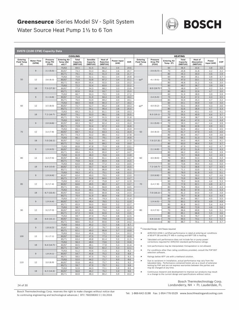
Bosch Thermotechnology Corp. reserves the right to make changes without notice due to continuing engineering and technological advances | BTC 760208302 C | 03.2016
Bosch Thermotechnology Corp.Londonderry, NH • Ft. Lauderdale, FL
Tel: 1-866-642-3198 Fax: 1-954-776-5529 www.boschheatingandcooling.com
Engineering Submittal Sheet
iSeries Model SV - Split System
Water Source Heat Pump 1½ to 6 Ton
24 of 30
COOLING HEATINGEntering
Fluid Temp (F)
Water Flow (GPM)
Pressure Drop PSI
(FOH)
Entering Air Temp (db/
wb) F
Total Capacity (MBTUH)
Sensible Capacity (MBTUH)
Heat of Rejection (MBTUH)
Power Input (kW) EER
Entering Fluid Temp
(F)
Pressure Drop PSI
(FOH)
Entering Air Temp (F)
Total Capacity (MBTUH)
Heat of Absorption (MBTUH)
Power Input (kW) COP
50
9 2.1 (5.5)75/63 69.5 51.5 81.2 3.5 19.6
30*
2.5 (5.7)60 46.4 33.6 3.8 3.6
80/67 74.3 53.3 86.2 3.6 20.7 70 45.8 31.8 4.2 3.285/71 79.1 55.1 91.3 3.6 21.7 80 45.3 30.0 4.6 2.9
12 3.6 (8.3)75/63 70.8 52.1 82.1 3.4 20.8
4.1 (9.5)60 48.0 35.1 3.8 3.7
80/67 75.8 53.8 87.2 3.4 22.1 70 47.0 33.1 4.2 3.385/71 80.9 55.4 92.5 3.5 23.2 80 46.8 31.2 4.6 3.0
18 7.5 (17.3)75/63 72.2 52.4 83.0 3.3 22.2
8.5 (19.7)60 49.7 36.7 3.9 3.8
80/67 77.3 54.3 88.2 3.3 23.6 70 48.9 34.7 4.2 3.485/71 82.6 55.9 93.7 3.3 25.0 80 48.3 32.6 4.7 3.0
60
9 2.1 (4.8)75/63 66.7 50.3 79.5 3.9 17.2
40*
2.4 (5.5)60 51.9 38.9 3.9 3.9
80/67 71.4 51.9 84.4 3.9 18.2 70 51.4 37.2 4.3 3.585/71 76.0 53.9 89.2 4.0 19.1 80 50.9 35.3 4.7 3.2
12 3.5 (8.0)75/63 68.0 50.8 80.3 3.7 18.2
4.0 (9.2)60 54.1 40.9 4.0 4.0
80/67 72.7 52.7 85.2 3.8 19.3 70 53.1 38.9 4.3 3.685/71 77.7 54.1 90.4 3.8 20.4 80 52.6 36.9 4.7 3.3
18 7.2 (16.7)75/63 69.2 51.3 81.1 3.6 19.3
8.3 (19.1)60 56.4 43.1 4.0 4.1
80/67 74.1 53.3 86.1 3.6 20.5 70 55.5 40.9 4.4 3.785/71 79.3 54.7 91.5 3.6 21.8 80 54.8 38.7 4.8 3.4
70
9 2.0 (4.6)75/63 63.9 48.9 77.8 4.2 15.1
50
2.1 (5.0)60 60.4 47.0 4.1 4.4
80/67 68.3 50.7 82.4 4.3 16.0 70 59.3 44.7 4.4 3.985/71 72.9 52.4 87.2 4.3 16.8 80 58.6 42.6 4.9 3.5
12 3.4 (7.8)75/63 65.1 49.4 78.5 4.1 15.9
3.6 (8.3)60 62.6 49.2 4.1 4.5
80/67 69.7 51.2 83.3 4.1 16.9 70 61.7 47.0 4.5 4.085/71 74.3 53.2 88.1 4.2 17.8 80 60.9 44.7 4.9 3.6
18 7.0 (16.1)75/63 66.1 50.1 79.1 3.9 16.8
7.5 (17.3)60 65.1 51.3 4.1 4.6
80/67 71.0 51.7 84.1 4.0 17.9 70 64.0 48.9 4.5 4.185/71 76.0 53.5 89.2 4.0 19.0 80 63.0 46.4 5.0 3.7
80
9 1.9 (4.5)75/63 60.8 47.8 75.9 4.6 13.1
60
2.1 (4.8)60 67.9 54.2 4.2 4.7
80/67 65.1 49.4 80.5 4.7 13.9 70 67.0 51.6 4.6 4.385/71 69.4 51.5 85.0 4.7 14.7 80 66.2 49.3 5.0 3.9
12 3.3 (7.5)75/63 61.9 48.3 76.6 4.5 13.8
3.5 (8.0)60 70.7 56.8 4.2 4.9
80/67 66.3 50.2 81.1 4.5 14.7 70 69.5 54.3 4.6 4.485/71 70.8 52.0 85.9 4.6 15.5 80 68.5 51.8 5.1 4.0
18 6.8 (15.6)75/63 63.0 48.8 77.2 4.3 14.5
7.2 (16.7)60 73.6 59.4 4.3 5.0
80/67 67.5 50.7 81.9 4.4 15.5 70 72.3 56.6 4.7 4.585/71 72.3 52.5 86.8 4.4 16.5 80 71.1 53.9 5.1 4.1
85
9 1.9 (4.4)75/63 59.2 47.1 75.1 4.8 12.2
70
2.0 (4.6)60 76.0 61.8 4.3 5.1
80/67 63.4 49.0 79.5 4.9 13.0 70 74.9 59.0 4.7 4.685/71 67.7 50.8 84.0 5.0 13.7 80 73.9 56.4 5.2 4.2
12 3.2 (7.4)75/63 60.4 47.3 75.8 4.7 12.9
3.4 (7.8)60 79.2 64.8 4.4 5.3
80/67 64.6 49.5 80.2 4.7 13.7 70 77.9 62.1 4.8 4.785/71 69.1 51.3 84.8 4.8 14.5 80 76.6 59.4 5.3 4.3
18 6.7 (15.4)75/63 61.4 48.1 76.3 4.5 13.5
7.0 (16.1)60 82.8 67.9 4.5 5.4
80/67 65.8 50.0 80.8 4.6 14.4 70 81.2 64.9 4.9 4.985/71 70.4 51.9 85.6 4.6 15.3 80 79.7 61.8 5.3 4.4
90
9 1.9 (4.4)75/63 57.7 46.5 74.3 5.1 11.4
80
1.9 (4.5)60 84.5 69.7 4.5 5.5
80/67 61.7 48.4 78.5 5.1 12.0 70 83.1 67.0 4.9 4.985/71 65.9 50.0 83.0 5.2 12.7 80 81.8 64.3 5.4 4.4
12 3.2 (7.3)75/63 58.7 46.9 74.8 4.9 11.9
3.3 (7.5)60 88.2 72.9 4.6 5.6
80/67 62.9 48.9 79.2 5.0 12.7 70 86.6 69.8 5.0 5.185/71 67.3 50.6 83.8 5.0 13.5 80 85.1 66.8 5.5 4.6
18 6.6 (15.1)75/63 59.7 47.4 75.3 4.8 12.5
6.8 (15.6)60 92.3 76.7 4.7 5.8
80/67 64.1 49.3 79.8 4.8 13.3 70 90.5 74.1 5.1 5.285/71 68.6 51.0 84.6 4.8 14.2 80 88.7 70.1 5.6 4.7
100
9 1.8 (4.2)75/63 54.4 45.2 72.7 5.6 9.780/67 58.2 47.2 76.7 5.6 10.385/71 62.1 49.3 80.8 5.7 10.9
12 3.1 (7.1)75/63 55.4 45.6 73.2 5.4 10.280/67 59.4 47.5 77.3 5.5 10.985/71 63.4 49.8 81.4 5.5 11.5
18 6.4 (14.7)75/63 56.3 46.0 73.6 5.3 10.680/67 60.5 48.1 77.8 5.3 11.485/71 64.7 50.2 82.2 5.3 12.1
110
9 1.8 (4.1)75/63 51.2 43.6 71.5 6.2 8.280/67 54.7 45.8 75.2 6.3 8.885/71 58.5 47.5 79.2 6.3 9.3
12 3.0 (6.9)75/63 52.0 44.2 71.7 6.0 8.680/67 55.8 46.0 75.7 6.1 9.285/71 59.7 47.9 79.7 6.1 9.8
18 6.2 (14.3)75/63 52.8 44.3 72.1 5.9 8.980/67 56.8 46.2 76.2 5.9 9.685/71 60.8 48.3 80.2 5.9 10.2
* Extended Range - Anti-freeze required
AHRI/ISO13256-1 certified performance is rated at entering air conditions of 80.6°F DB and 66.2°F WB in cooling and 68°F DB in heating.
Tabulated unit performance does not include fan or pump power corrections required for AHRI/ISO standard performance ratings.
Unit performance may be interpolated. Extrapolation is not allowed.
For conditions other than rating conditions provided, consult the FHP BST selection software.
Ratings below 40°F are with a methanol solution.
Due to variations in installation, actual performance may vary from the tabulated data. Performance contained herein are as a result of extensive testing by FHP and are not express warranties between the parties and may be changed at any time.
Continuous research and development to improve our products may result in a change to the current design and specifications without notice.
SV070 (2100 CFM) Capacity Data

Bosch Thermotechnology Corp. reserves the right to make changes without notice due to continuing engineering and technological advances | BTC 760208302 C | 03.2016
Bosch Thermotechnology Corp.Londonderry, NH • Ft. Lauderdale, FL
Tel: 1-866-642-3198 Fax: 1-954-776-5529 www.boschheatingandcooling.com
Engineering Submittal Sheet
iSeries Model SV - Split System
Water Source Heat Pump 1½ to 6 Ton
25 of 30
Antifreeze Correction
Antifreeze Type Antifreeze %
Cooling HeatingWPD Correction Factor EWT 30 °FEWT 90 Deg.F EWT 30 Deg. F
Total Cap. Sens. Cap Power Htg. Cap Power
Water 0 1.000 1.000 1.000 1.000 1.000 1.000
Propylene Glycol
5 0.997 0.997 1.004 0.989 0.997 1.060
10 0.994 0.994 1.006 0.986 0.995 1.125
15 0.990 0.990 1.009 0.978 0.988 1.190
25 0.983 0.983 1.016 0.960 0.979 1.300
Methanol
5 0.997 0.997 1.003 0.990 0.997 1.060
10 0.996 0.996 1.005 0.979 0.993 1.100
15 0.994 0.994 1.008 0.970 0.990 1.140
Ethanol
5 0.998 0.998 1.002 0.981 0.994 1.160
10 0.996 0.996 1.004 0.960 0.988 1.230
15 0.992 0.992 1.006 0.944 0.983 1.280
25 0.986 0.986 1.009 0.917 0.974 1.400
Ethylene Glycol
5 0.997 0.997 1.003 0.993 0.998 1.060
10 0.995 0.995 1.004 0.986 0.996 1.120
15 0.992 0.992 1.005 0.980 0.993 1.190
25 0.988 0.988 1.009 0.970 0.990 1.330
30 0.985 0.985 1.012 0.965 0.987 1.400

Bosch Thermotechnology Corp. reserves the right to make changes without notice due to continuing engineering and technological advances | BTC 760208302 C | 03.2016
Bosch Thermotechnology Corp.Londonderry, NH • Ft. Lauderdale, FL
Tel: 1-866-642-3198 Fax: 1-954-776-5529 www.boschheatingandcooling.com
Engineering Submittal Sheet
iSeries Model SV - Split System
Water Source Heat Pump 1½ to 6 Ton
26 of 30
Waterside Pressure Drop
Model Water FlowRate (GPM)
Water Side Pressure Drop with out Internal Valve (PSI)
Water Side Pressure Drop with Internal Valve (PSI)
SV018
2.5 1.1 2.1
4 2.7 5.2
5 4.0 8.0
SV024
3 1.7 2.0
4 2.8 3.4
6 5.8 7.2
SV030
4 2.0 2.6
6 4.2 5.6
8 7.0 9.6
SV036
4.5 1.6 2.4
6 2.6 4.0
9 5.4 8.6
SV042
5 2.0 3.0
8 4.6 7.2
11 8.2 13.0
SV048
6 0.8 1.4
8 1.4 2.5
12 2.8 5.4
SV060
7.5 1.4 2.4
10 2.3 4.1
15 4.8 8.8
SV070
9 2.0 3.4
12 3.4 5.9
18 7.0 12.7
All values based upon pure water at 70° F.

Bosch Thermotechnology Corp. reserves the right to make changes without notice due to continuing engineering and technological advances | BTC 760208302 C | 03.2016
Bosch Thermotechnology Corp.Londonderry, NH • Ft. Lauderdale, FL
Tel: 1-866-642-3198 Fax: 1-954-776-5529 www.boschheatingandcooling.com
Engineering Submittal Sheet
iSeries Model SV - Split System
Water Source Heat Pump 1½ to 6 Ton
27 of 30
Factory Installed Options and Applicable Models
Condenser Section – Unit SIze
Description SV018 SV024 SV030 SV036 SV042 SV048 SV060 SV070
208-230/1/60 • • • • • • • •277/1/60 • • • • • • • •208-230/3/60 • • • • • • •460/3/60 • • • • • • •Cupro-Nickel Coaxial Condensor Coil • • • • • • • •Disconnect Switch • • • • • • • •Compressor Monitor Relay • • • • • • • •Phase Monitor (3 phase only) • • • • • • • •Boilerless Control • • • • • • • •Differential Pressure Switch • • • • • • • •LED Light Display • • • • • • • •2 Way Solenoid Valve • • • • • • • •Measure/Flow Device (3 GPM/Ton) • • • • • • • •Combo 2 Way Solenoid & Measure Flow • • • • • • • •
Factory Installed Options and Applicable Models
Air Handler / Fan Coil Section – Unit SIze
Description SV018 SV024 SV030 SV036 SV042 SV048 SV060 SV070
208-230/1/60 • • • • • • • •277/1/60 • • • •460/3/60 • • • • • • •Energy Management Relay • • • • • • • •Fire Alarm Relay • • • • • • • •Blower Monitor Relay • • • • • • • •Disconnect Switch • • • • • • • •Wire for 208 Volt • • • • • • • •4 Sided Filter Rack with MERV-8 Filter • • • • • • • •4 Sided Filter Rack with MERV-13 Filter • • • • • • • •75, 100 VA Transformer • • • • • • • •

Bosch Thermotechnology Corp. reserves the right to make changes without notice due to continuing engineering and technological advances | BTC 760208302 C | 03.2016
Bosch Thermotechnology Corp.Londonderry, NH • Ft. Lauderdale, FL
Tel: 1-866-642-3198 Fax: 1-954-776-5529 www.boschheatingandcooling.com
Engineering Submittal Sheet
iSeries Model SV - Split System
Water Source Heat Pump 1½ to 6 Ton
28 of 30
1.0 General
Furnish and install BOSCH SV series water source heat pumps as indicated on the plans with capacities and characteristics as listed in the schedule and the specifi cations that follow. The units shall be manufactured in an ISO 9001:2000 certifi ed facility.
2.0 Horizontal/Vertical Water Source Heat Pumps
Units shall be designed to operate throughout the range of entering fl uid temperature of 50°F to 110°F in the cooling mode and 30°F to 80°F in the heating mode. Equivalent units from other manufacturers can be proposed provided approval to bid is given 10 days prior to bid closing. All equipment with a nominal capacity of 134,000 BTUH Total Cooling or lower must be listed in the current AHRI Applied Equipment Directory under the AHRI Standard ISO- 13256-1 Rating. All equipment in this section must meet or exceed the national stan-dard minimum EER and COP as listed in ASHRAE 90.1 All units shall conform to UL1995 standard and certifi ed to CAN/CSA C22.1 No 236 by Intertek-ETL. All units shall have ARI-13256-1 labels, and ETL/UL or NRTL or CSA labels.
2.01 Basic Construction
A. Units shall have the air fl ow arrangement as shown on the plans. If units with these arrangements are not used, the con-tractor supplying the water source heat pumps is responsible for any extra costs incurred by other trades and must submit de-tailed mechanical drawings showing duct work requirements and changes or relocation of any other mechanical or electrical sys-tem. If other arrangements make servicing diffi cult the contractor must provide access panels and clear routes to ease service. The architect must approve all changes 10 days prior to bid.
B. All units shall have stainless steel drain pans to comply with this project’s IAQ requirements. No exceptions shall be allowed.
C. All water source heat pumps shall be fabricated from sheet metal fi nished with galvanized steel. All interior surfaces shall be lined with 1/2 inch thick, multi density acoustic insulation. All insulation must meet NFPA 90A and be certifi ed to meet the GREENGUARD Indoor Air Quality Standard for Low Emit-ting Products. One blower access panel and one compressor compartment access panels shall be removable with supply and return air duct work in place.
D. Unit shall have a fl oating base pan consisting of a ½" (12 mm) thick high density rubber pad between the compressor base plate and the unit base pan to prevent transmission of vibration to the structure.
E. All units shall have a factory installed two sided fi lter rack capable of accepting one inch fi lters. Units shall have a 1 inch
thick throwaway type glass fi ber fi lter as standard. The fi lter rack shall incorporate a 1 inch duct fl ange. The contractor shall purchase one spare set of fi lters and replace factory-shipped fi lters upon completion of start-up.
— Option to E: All units shall have a factory installed four sided filter rack with 2” MERV-8 filters.
— Option to E: All units shall have a factory installed four sided filter rack with 2” MERV-13 filters.
F. Cabinets shall have separate holes and knockouts for entrance of line voltage and low voltage control wiring. Supply and return water connections shall be brass FPT fi ttings and shall be securely mounted fl ush to the cabinet allowing for connection to a fl exible hose without the use of a back-up wrench. Water connections which protrude through the cabinet shall not be allowed.
G. Hanging brackets shall be provided as standard for horizontal units.
H. All units shall have water-coil freeze sensor as standard.
2.02 Fan and Motor Assembly
A. Unit comes standard with Constant Torque CFM ECM. — Option A: The fan motor shall be a pre-programmed
high efficiency constant torque ECM type. — Option B: Variable Speed Constant CFM electronically
commutative motor (ECM). B. The fan and motor assembly must be capable of overcoming
the external static pressures as shown on the schedule. External static pressure rating of the unit shall be based on a wet coil. Ratings based on a dry coil shall NOT be acceptable.
C. All units shall have removable blower inlet ring as standard for ease of service and maintenance.
2.03 Refrigerant Circuit
Units shall use R-410A refrigerant. All units shall have a factory sealed and fully charged refrigerant circuit with the following components:A. Compressors shall be hermetic single stage,reciprocating or scroll type specifi cally designed for heat pump operation and shall be internally sprung with thermal overload protection and mounted on rubber vibration isolators. B. Refrigerant metering Thermal Expansion Valve (TXV).C. Finned tube refrigerant to air heat exchanger not exceeding 16 fi ns per inch. Refrigerant to air heat exchangers shall utilize enhanced aluminum fi ns and rifl ed copper tube construction rated to withstand 600 PSIG refrigerant working pressure. All air coils shall have non-ferrous aluminum end plates.
— Option for C: Coils shall have DuoGuardTM tin electro-plated copper tubing with polymer coated Aluminum
Specifi cation Guide Continued

Bosch Thermotechnology Corp. reserves the right to make changes without notice due to continuing engineering and technological advances | BTC 760208302 C | 03.2016
Bosch Thermotechnology Corp.Londonderry, NH • Ft. Lauderdale, FL
Tel: 1-866-642-3198 Fax: 1-954-776-5529 www.boschheatingandcooling.com
Engineering Submittal Sheet
iSeries Model SV - Split System
Water Source Heat Pump 1½ to 6 Ton
29 of 30
Fins coating for enhanced protection against formicary and other types of corrosion. Copper tubes shall be tin coated and aluminum fins coated to pass 1000 hour ASTM B117 salt spray testing.
D. Reversing valve. Reversing valves shall be four way solenoid activated refrigerant valves which shall fail to the heating operation should the solenoid fail to function. Reversing valves which fail to the cooling operation shall not be allowed.
E. Coaxial (tube in tube) refrigerant to water heat exchanger. Refrigerant to water heat exchangers with copper inner water tube and steel outer refrigerant tube design rated to withstand 600 PSIG working refrigerant pressure and 400 PSIG working water pressure. Shell and Tube style refrigerant to water heat exchangers shall be treated as pressure vessels and shall require refrigerant pressure relief valves piped to the exterior of the building. The contractor supplying the water source heat pumps with Shell and Tube heat exchangers shall be responsible for any additional installation costs. Brazed Plate water to refrigerant heat exchangers shall require additional centrifugal separators added to the supply water piping at each unit. Each separator shall have an automated clean out valve piped to a waste line. The contractor supplying water source heat pumps with Brazed Plate heat exchangers shall be responsible for any additional costs.
— Option for E: Cupro-Nickel water coil – The refrigerant to water heat exchanger shall be of cupro-nickel inner water tube construction.
F. Safety controls including both a high pressure and low pressure switch. Temperature sensors shall not replace these safety switches. See the controls section of this specifi cation for additional information.
G. Access fi ttings shall be factory installed on high and low pressure refrigerant lines to facilitate fi eld service.
H. Activation of any safety device shall prevent compressor operation via a lockout circuit. The lockout circuit shall be reset at the thermostat or at the contractor supplied disconnect switch. Units which may be reset at the disconnect switch only shall not be acceptable. Refer to solid state safety circuit below.
2.04 Electrical
A control box shall be located within the unit and shall contain a transformer, controls for the compressor, reversing valve and fan motor operation and shall have a terminal block for low voltage fi eld wiring connections. The transformer shall be rated for a minimum 50 VA and shall have a push button reset circuit breaker on the secondary power.
All units shall be name-plated for use with time delay fuses or HACR circuit breakers. Unit controls shall be 24 volts.
2.05 Solid State Safety Circuit
All units shall have a solid-state UPM safety control circuit with the following features:
1. Anti-short cycle time delay on compressor operation.2. Random start on power up mode.3. Brown out/Surge/Power Interruption protection.4. Low Pressure Switch 120 second bypass timer.5. Shutdown on the following fault indications:
a. high or low refrigerant pressure safety switches inputs.b. Freeze sensors shall monitor refrigerant temperature to
the water coil in the heating mode and refrigerant to air coil in the cooling mode.
6. Alarm output which closes for selectable dry contact closure or 24 VAC remote fault indication.
7. Alarm output selectable for constant output for general alarm notifi cation, or pulse output for annunciation of the specifi c fault alarm.
8. Selectable reset of unit at thermostat or disconnect.9. Automatic intelligent reset. Unit shall automatically reset
after a safety shut down and restart the unit after the anti-short cycle timer and random start timer expire. Should the same fault re-occur within 60 minutes after reset, then a permanent lockout will occur. Reset attempts shall be selectable for either 2 or 4 tries. A condensate overfl ow will place the unit in an immediate hard lockout.
10. Ability to defeat time delays for servicing.11. A light emitting diode (LED) to indicate safety alarms. The
LED shall annunciate the following alarms: a. high refrigerant pressure, b. low refrigerant pressure, c. low refrigerant temperature to the water coil in the
heating operation, d. brown out/surge/ power interruption.
12. The LED will display each fault condition as soon as the fault occurs. If a permanent lockout occurs, then the fault LED will display the type of fault until the unit is reset.
13. UL listed, CUL listed, and RFI, ESD, and transient protected.
Freeze Protection: A freeze stat shall sense the entering refrigerant temperature to the coaxial coil (in the heating mode) and shall activate the compressor lockout circuit when the refrigerant temperature drops below either 15⁰F or 30⁰F. The factory default is 30⁰F and the temperature setting may be set at 15⁰F by cutting the resistor (R42) located above dip switch. The freeze stat may not provide protection in the case of loss of fl ow in the heating mode.
Specifi cation Guide Continued

Bosch Thermotechnology Corp. reserves the right to make changes without notice due to continuing engineering and technological advances | BTC 760208302 C | 03.2016
Bosch Thermotechnology Corp.Londonderry, NH • Ft. Lauderdale, FL
Tel: 1-866-642-3198 Fax: 1-954-776-5529 www.boschheatingandcooling.com
Engineering Submittal Sheet
iSeries Model SV - Split System
Water Source Heat Pump 1½ to 6 Ton
30 of 30
Specifi cation Guide Continued
2.06 Options
A. Extra quiet construction: Optional compressor blanket shall be provided on units having a capacity above 24,000 BTUH.
B. DDC Controls: Unit shall be equipped with a factory installed DDC control capable of interfacing with BacNet, Modbus, and N2 and Lonworks. When choosing Lonworks, a separate Lon card must be purchased. The controller shall be pre-programmed to control the unit and monitor the safety controls. The unit shall be able to operate as a standalone or be incorporated into the building management system. A leaving water and leaving air sensor shall be installed in the unit. Wall sensors shall be available for controlling zone temperature.
C. Unit mounted disconnect. A non fused factory mounted disconnect shall be installed on the unit.
D. Two Way Motorized Water valve: A two way motorized water valve shall be mounted in the interior of the unit. The valve shall cycle open whenever there is a call for compressor operation. The valve shall be equipped with an end switch.
E. The following relays shall be factory installed in the unita) EMS Relay for remote enabling of the unit.b) Auxiliary pump or valve relay to enable a pump or valve
operation when calling for compressor operation.F. A Comfort Alert Module can be ordered separately for Scroll
compressors. This device assist in service diagnostics. shall be installed in the units to assist in service diagnostics
3.0 Hose Kits
All units shall be connected with hoses. The hoses shall be either 2 or 3 feet long, braided stainless steel, fi re rated hoses. Non fi re rated hoses are not acceptable. Optional ball valves with P/T ports, fl ow controller, Y strainer and electric valve shall be in included as specifi ed in the schedule.