is/iec 60534-2-3 (1997): industrial-process control valves ...control valves - part 2-3: flow...
TRANSCRIPT

Disclosure to Promote the Right To Information
Whereas the Parliament of India has set out to provide a practical regime of right to information for citizens to secure access to information under the control of public authorities, in order to promote transparency and accountability in the working of every public authority, and whereas the attached publication of the Bureau of Indian Standards is of particular interest to the public, particularly disadvantaged communities and those engaged in the pursuit of education and knowledge, the attached public safety standard is made available to promote the timely dissemination of this information in an accurate manner to the public.
इंटरनेट मानक
“!ान $ एक न' भारत का +नम-ण”Satyanarayan Gangaram Pitroda
“Invent a New India Using Knowledge”
“प0रा1 को छोड न' 5 तरफ”Jawaharlal Nehru
“Step Out From the Old to the New”
“जान1 का अ+धकार, जी1 का अ+धकार”Mazdoor Kisan Shakti Sangathan
“The Right to Information, The Right to Live”
“!ान एक ऐसा खजाना > जो कभी च0राया नहB जा सकता है”Bhartṛhari—Nītiśatakam
“Knowledge is such a treasure which cannot be stolen”
“Invent a New India Using Knowledge”
है”ह”ह
IS/IEC 60534-2-3 (1997): Industrial-Process Control Valves,Part 2: Flow Capacity, Section 3: Test Procedures [ETD 18:Industrial Process Measurement and Control]


I8nEC 60534-2-3: 1997
'J.f7'<rf)2/ lfFfCf)
~-o.wSOf ~li?lOI qlc;q
Indian StandardINDUSTRIAL-PROCESS CONTROL VALVES
PART 2 FLOW CAPACITYSection 3 Test Procedures
ICS 29.060.40; 25.040.40
©SIS2008
BUREAU OF INDIAN STANDARDSMANAK SHAVAN, 9 SAHADUR SHAH ZAFAR MARG
NEW DELHI 110002
October 2008 Price Group 9
Industrial Process Measurement and Control Sect ional Committee , ETD 18
NATIONAL FOREWORD
This Indian Standard (Part 2/Sec 3) which is identical with IEC 60534-2-3 : 1997 'Industria l-processcontrol valves - Part 2-3: Flow capacity - Test procedures' issued by the Internat ionalElectrotechnical Commission (IEC) was adopted by the Bureau of Indian Standards on therecommendation of the Industrial Process Measurement and Control Sectional Committee andapproval of the Electrotechnical Division Council.
The text of IEC Standard has been approved as suitable for publication as an Indian Standard withoutdeviations. Certain conventions are, however, not identical to those used in Indian Standards.Attention is particularly drawn to the following :
a) Wherever the words 'International Standard' appear referring to this standard , they shouldbe read as 'Indian Standard' .
b) Comma (,) has been used as a decimal marker, while in Indian Standards, the currentpractice is to use a point (.) as the decimal marker.
In this adopted standard, reference appears to certain International Standards for which IndianStandards also exist. The corresponding Indian Standards, which are to be subst ituted in theirrespective places are listed below along with their degree of equivalence for the editions indicated:
International Standard
IEC 60534-1 : 1987 Industrial-processcontrol valves - Part 1: Control valveterminology and general considerations
IEC 60534-2-1 : 19781) Industrial-process
control valves - Part 2: Flow capacity Section 1: Sizing equations forincompressible fluid flow under installedconditions
IEC 60534-2-2 : 198(2) Industrial-processcontrol valves - Part 2: Flow capac ity Section 2: Sizing equations forcompressible fluid flow under installedconditions
Corresponding Indian Standard
IS/IEC 60534-1 : 1987 Industrial-processcontrol valves: Part 1 Control valveterminology and general considerations .
IS/IEC 60534-2-1 : 1998 Industrialprocess control valves: Part 2 ' Flowcapacity, Section 1 Sizing equations forincompressible fluid flow under installedconditions
IS/IEC 60534-2-2 : 1993 Industrialprocess control valves: Part 2 Flowcapacity, Section 2 Sizing equat ions forcompressible fluid flow under installedconditions
Degree ofEquivalence
Identical
TechnicallyEquivalent
do
The technical committee has reviewed the provisions of the following International Standards referredin this adopted standard and has decided that they are acceptable for use in conjunction with thisstandard:
International StjJndard
IEC 60534-8-2 : 1991
IEC 61298-1 : 1995
1) Since revised in 1998.
2) Since revised in 1993.
Title
Industrial-process control valves - Part 8: Noise considerations Section 2: Laboratory measurement ot noise generated by hydrodynamicflow through control valves
Process measurement and control devices - General methods andprocedures for evaluating performance - Part 1: General considerations
(Continued on third cover)
ISIIEC 60534-2-3: 1997
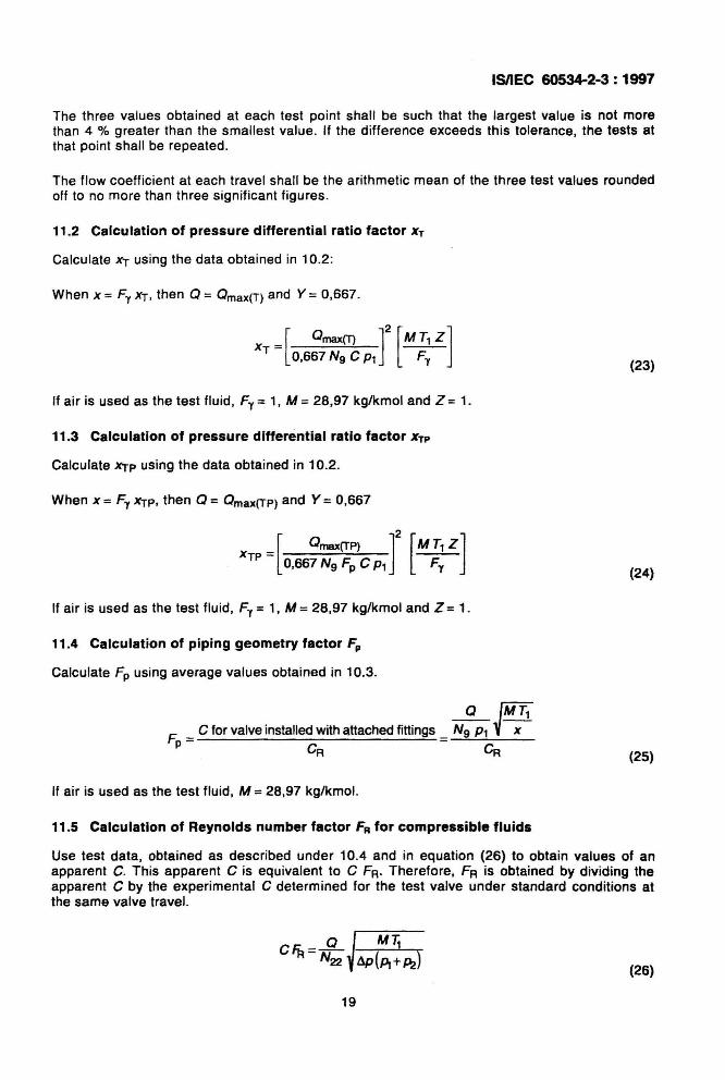
The three values obtained at each test point shall be such that the largest value is not morethan 4 % greater than the smallest value. If the difference exceeds this tolerance, the tests atthat point shall be repeated.
The flow coefficient at each travel shall be the arithmetic mean of the three test values roundedoff to no more than three significant figures.
11.2 Calculation of pressure differential ratio factor XT
Calculate XT using the data obtained in 10.2:
When x == Fy xT, then Q == Qmax(T) and Y == 0,667.
[ ]2 [ ]
Qmax(T) M T1 ZxT = 0,667 Ng e P1 ---;=;-
If air is used as the test fluid, Fy = 1, M = 28,97 kg/kmol and Z = 1.
11.3 Calculation of pressure differential ratio factor XTP
Calculate XTp using the data obtained in 10.2.
When x =Fy XTp, then Q = Qmax(TP) and Y = 0,667
XTP = [ Qmax(TP) ]2 [MF.~z]0,667 Ng Fp e P1 •
If air is used as the test fluid, Fy = 1, M = 28,97 kg/kmol and Z = 1.
11.4 Calculation of piping geometry factor Fp
Calculate Fp using average values obtained in 10.3.
(23)
(24)
F._ e for valve installed with attached fittings
p- eA
If air is used as the test fluid, M == 28,97 kg/kmol.
(25)
11.5 Calculation of Reynolds number factor FR for compressible fluids
Use test data, obtained as described under 10.4 and in equation (26) to obtain values of anapparent C. This apparent e is equivalent to e FR. Therefore, FA is obtained by dividing theapparent e by the experimental e determined for the test valve under standard conditions atthe same valve travel.
(26)
19

ISIIEC 60534-2-3: 1997
Although the data may be correlated in any manner suitable to the experimenter, a method thathas proven to provide satisfactory correlations involves the use of the valve Reynolds number,which may be calculated from equation (13) where Fd is calculated as per 11.6.
11.6 calculation of valve style modifier Fd
Using the data obtained in 10.1, calculate Fd using equation (14) or (15) as appropriate.
11.7 Calculation of flow coefficient Cfor amall flow trim
Using the data obtained in 10.2.6, calculate C from the following equation and average theresults:
Table 3 - Numerical constants N
(27)
Flow coefficient C Formulee units
ConNnt K. e, Q p,.s".".. P T d v
N, 1,00 x 10" 8,65 x 10- 2 m3/h kPa bar kglm 3 - - -1,00 8,65 X 10-' m3/h kg/m3
N. 7,07 x10⁻² 7,60 x 10⁻² m3/h - - - - m2/s
Nt 2,46 x 10' 2,12 x 10' m3/h kPa bar - K - -It" c O'C) 2,46 x 10³ 2,12 x 10³ m3/h K
Nt 2,60 x 10' 2,25 X 10' m3/h kPa bar - K - -It" z 15 'C) 2,60 x 10³ 2,25 X 10³ m3/h K
N,. 8,65 X 10-' 1,00 - - - - mm -Ha, 1,3)( 10-3 1,4 x 10. 3 - kPa bar - - - -
1,3)( 10" 1,4)( 10"
Ha2 1,73)( 10' 1,50x10' m3/h kPa bar - K - -(t". 0 'C) 1,73 x 10³ 1,50 x 10³ m3/h K
Hal 1,84 x 10' 1.59 x 10' m3/h kPa bar - K - -(t" • 15 'C) 1,84)( 103 1,59)( 103 m3/h K
Has 4,02 X 10. 2 4,65)( 10.2 .. - - - mm -Nat 1,28 X 10' 9,00 x 10' m3/h - - - - m2/s
N.J, 2,1 )( 10' 1,9)( 10' m3/h - - - - m2/s
N» 1,40 x 10² 1,27 X 10² - - - - mm -NOTE - Use 01the numerical constants provided in this table together with the practical metric units specified inthe table WIll yield flow coefficients in the units in which they are defined.
20
ISIIEC 60534-2·3: 1997
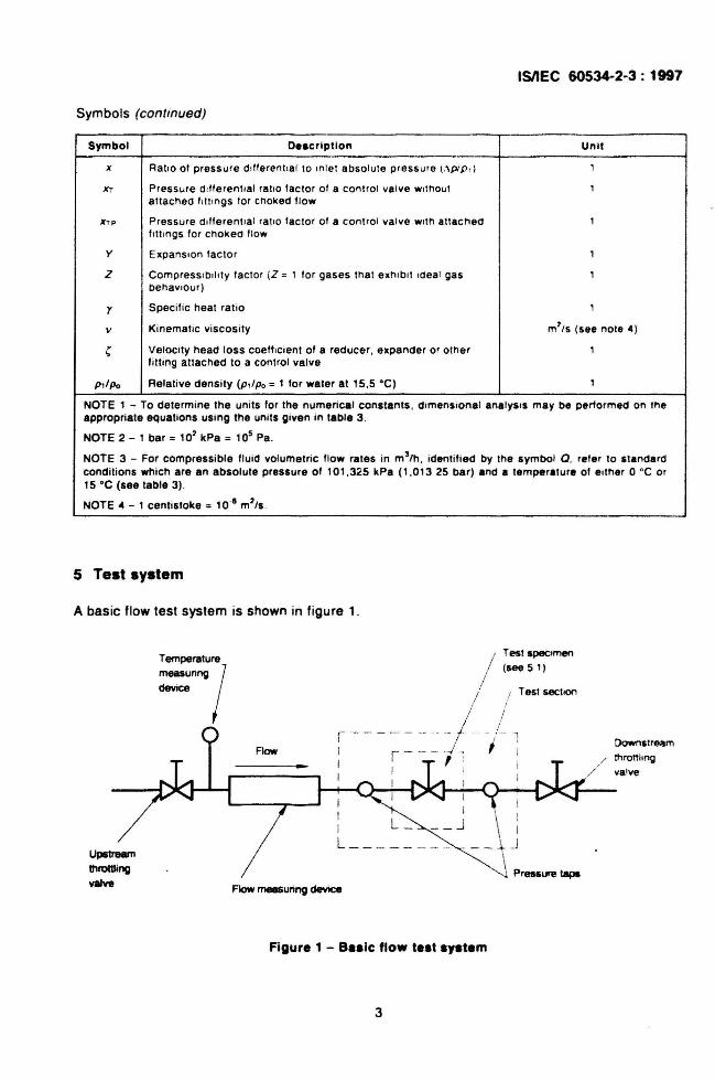
Symbols (continued)
Symbol D••crlptlon Unit
x Ratio 01 pressure d,fferenlial to tnlet absolute pressure (.\plp ,) ,Xl Pressure dlfferent,al ratio lactor of a control valve without ,
attached IllItngs for choked flow
XTP Pressure ll,lferenllal ratio tactor 01 a control valve with anscneo ,Ioll ings lor choked flow
y Expansion tactor ,Z Compressibility lactor (Z =, lor gases that exmbrt Ill eal gas ,
behaviour)
r Specilic heal ratio ,v Kinematic viscosity m'/s (see note 4)
c Velocity head loss coefficient of a reducer, expander or other ,fitting attached to a control valve
P"Po Relative density (p ,lpo =, lor water at 15 .5 'C) 1
NOTE 1 - To determine the units lor the numerical constants. dimensional analysIs may be perlormed on lheappropriate equations using the units given in table 3 .
NOTE 2 - 1 bar =10' kPa = 105 Pa .
NOTE 3 - For compressible fluid volumetric flow rates in m 3(h. identified by the symbol Q . reler to standardconditions which are an absolute pressure 01101 .325 kPa (1 .01325 bar) and a temperature 01 either O 'C or15 'C (see table 3) .
NOTE" - 1 centistoke =10 '8 m'/s .
5 Test system
A basic flow test system is shown in figure 1.
Test specimen(see 51)
\ '__ ~ .J
\ Pressure laps
DownstrMm
thronhngvalve
Test Sect ion/;
/t. ..
I
Flow measuring device
//
j!
r - -- --Ii1 i
I--+--<--J--i-I-I t-~:-'\. r-,...-.....
'-----r--~ I
I L JL _
UpstrellmthrotlIing
valve
Figure 1 - a.sic flow test system
3
ISIIEC 60534-2-3: 1997
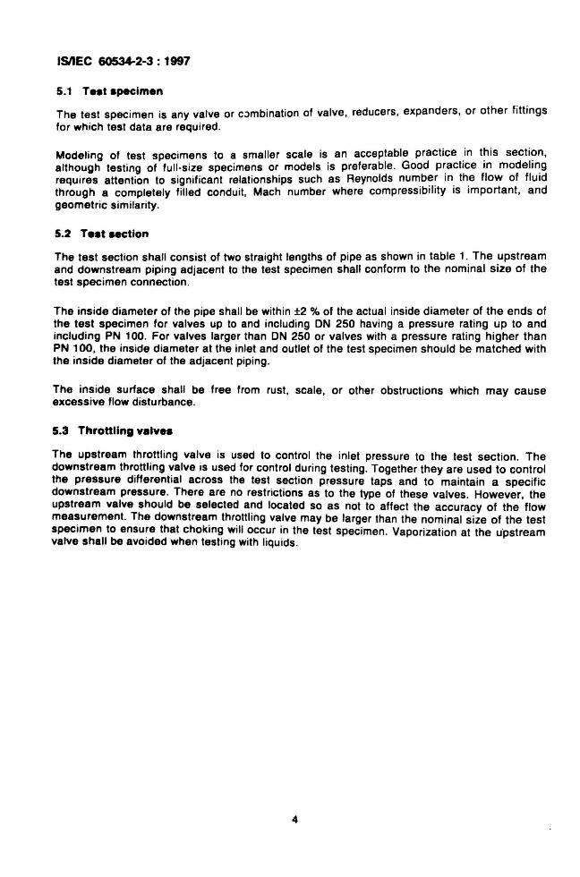
5.1 Te.t .pecimen
The test specimen is any valve or combination of valve, reducers , expanders, or other fitt ingsfor which test data are required.
Modeling of test specimens to a smaller scale is an acceptable practice .in t~is secti?n,although testing of full-s ize spec imens or models is preferable. Good p~actlce In modeh~g
requires attention to signif icant relationships such as Reynolds num.b~~ In . th.e flow of fluidthrough a completely filled conduit, Mach number where compressibility IS Important, andgeometric similarity.
5.2 Te.t section
The test section shall consist of two stra ight lengths of pipe as shown in table 1. The upstreamand downstream piping adjacent to the test specimen shall conform to the nominal size of thetest specimen connection.
The inside diameter of the pipe shall be within ±2 % of the actual inside diameter of the ends ofthe test specimen for valves up to and including ON 250 having a pressure rating up to andincluding PN 100. For valves larger than ON 250 or valves with a pressure rating higher thanPN 100, the inside diameter at the inlet and outlet of the test specimen should be matched withthe inside diameter of the adjacent piping.
The inside surface shall be free from rust, scale , or other obstructions which may causeexcessive flow disturbance.
5.3 Throttling v.lve.
The upstream throttling valve is used to control the inlet pressure to the test section. Thedownstream throttling valve is used for control during testing. Together they are used to controlthe pressure differential across the test section pressure taps and to maintain a specificdownstream pressure. There are no restrictions as to the type of these valves. However, theupstream valve should be selected and located so as not to affect the accuracy of the flowmeasurement. The downstream throttling valve may be larger than the nominal size of the testspecimen to ensu~e that choking will occur in the test specimen. Vaporization at the upstreamvalve shall be avotded when testing with liquids.
4

•
ISIIEC 605~2-3 : 1997
Table 1 - Te.t .ection piping requirement.
" ~ ~ '.Two times nominal pipe S IX limes nominal p.pe E,ghteen t.me, nomina' One lime, nominal ptpe
diameter dia mete r pipe diameter minimum diameter minimum
Standard test sec tion con figuration
Pressure ~ure
tap tap
I Flow .-+-- 13, I I,---j I I~-
I
I I- b 0 0 6--/,+1;, I ~T~_I
. 1,+4 .
NOTE 1 - Stra igh ten ing vanes may be used where benefic ia" II employed , the length " may be reduced to notless than eight times the nom inal p.pe diameter.
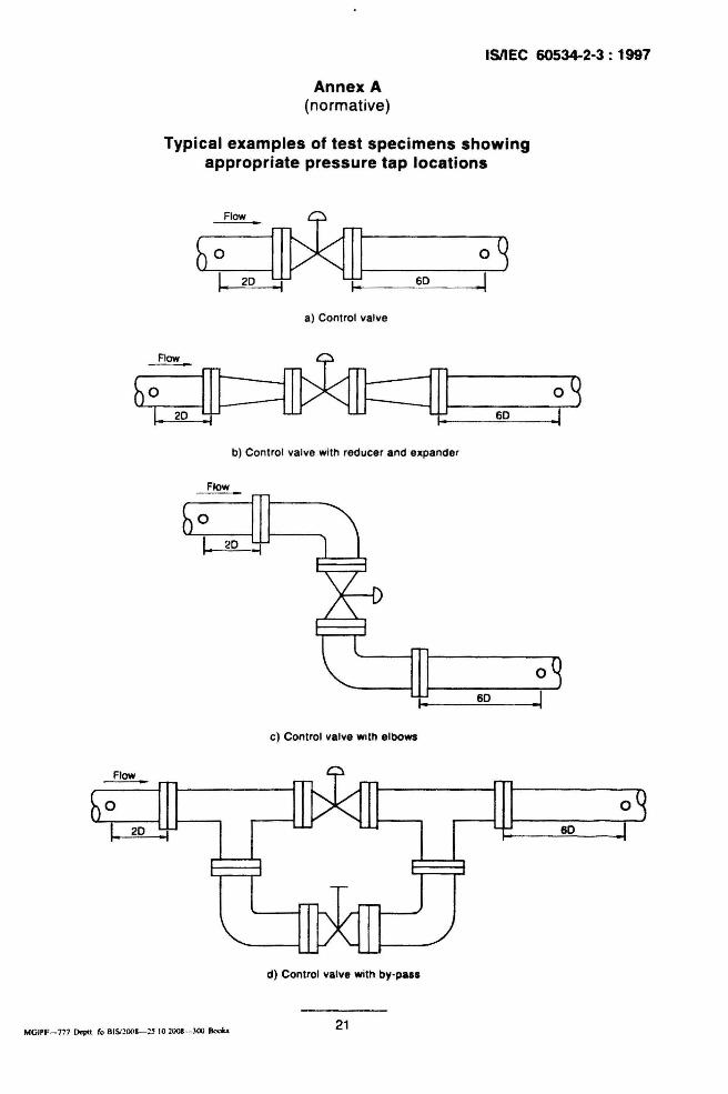
NOTE 2 - The location of the pressure tap, are upltream and downltream of the telt lpecimen u a whOle . Thetest specimen may be simply the control valve or the control valve with any comblnatlon of attached finingl (INannex A) .
NOTE 3 - II upst ream flow dis turbance conliltl of two elboWi In lenel and they are in differant planel, thedimenlion " shou ld exceed 1B nominal pipe diameters unle.. Itralghtening vanel are used .
5.4 Flow mea.urement
The flow measuring instrument may be located upstream or downatream of the teat .ection,and may be any device which meets the spec if ied accuracy, and .hall be calibrated a.frequently as necessary to maintain this accuracy. This instrument shall be uaed to determinethe true time-average flow rate within an accuracy of ±2 % of the actual value.
5.5 Pre••ure tap•
Pressure taps shall be provided on the test sect ion piping in accordance with the requirementsin table 1 and shall conform to the construction illustrated in figure 2. When the flow patternacross the pipe is not uniform, mul tiple taps may be necessary to ach ieve the de.ired accu racyof measurement.
The pressure tap diameter b shall be at least 3 mm and shall be not larger than 12 mm , or onetenth nom inal pipe diameter, whichever is less. Upstream and downstream taps sha ll be of thesame diameter.
The hole shall be circular and its edge shall be clean and sharp or slightly rounded, free fromburrs , wire edges . or other irregularities.
Any suitable method of mak ing phys ical connection is acceptable prov ided the aboverecommendations are adhered to; however. in no case shall any fiUing protrude in.ide the pipe .
S
ISIIEC 60534-2-3: 1997
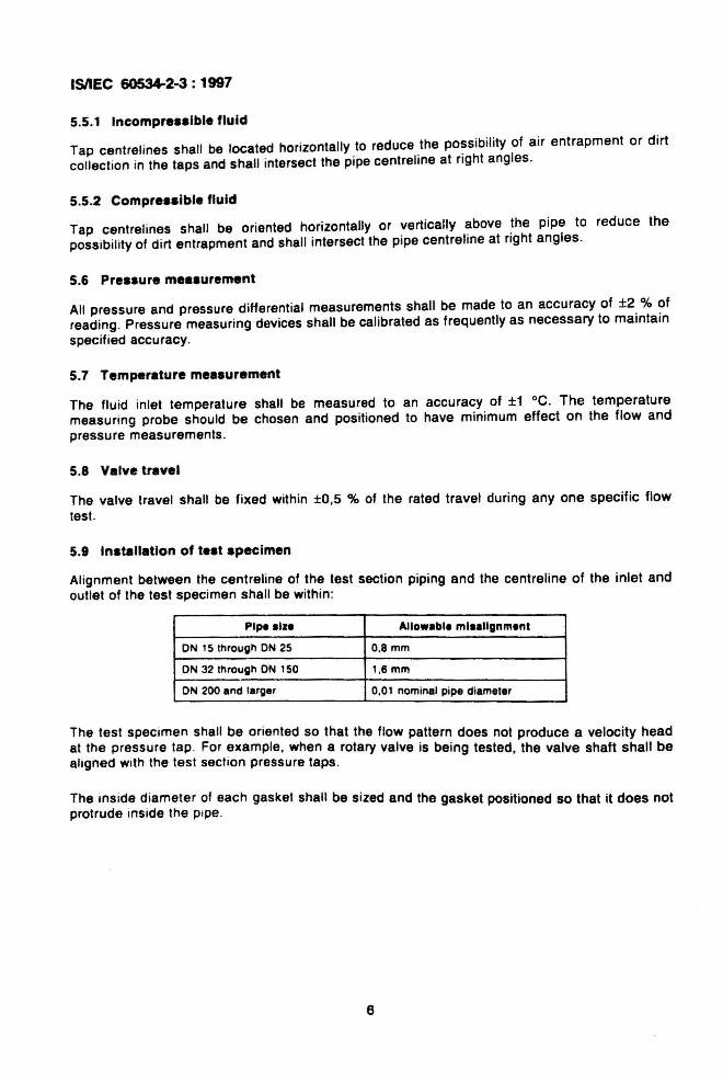
5.5.1 Incompre••lbl. fluid
Tap centrel ines shall be located horizontally to reduce the possibility of air entrapment or dirtcollection in the taps and shall intersect the pipe centreline at right angles.
5.5.2 Compre••lbl. fluid
Tap centrel ines shall be oriented horizontally or vertically above the pipe to reduce thepossibi lity of dirt entrapment and shall intersect the pipe centreline at right angles.
5.6 Pre••ure mea.ur.ment
All pressure and pressure differential measurements shall be made to an accuracy of ±2 % ofreading. Pressure measuring devices shall be calibrated as frequently as necessary to maintainspecified accuracy.
5.7 Temperature mea.urement
The fluid inlet temperature shall be measured to an accuracy of ±1 °e. The temperaturemeasuring probe should be chosen and posit ioned to have minimum effect on the flow andpressure measurements.
5.8 Valve travel
The valve travel shall be fixed within ±O.5 % of the rated travel during anyone specific flowtest.
5.9 In.tallation of t••t .pecimen
Alignment between the centreline of the test section piping and the centreline of the inlet andoutlet of the test specimen shall be within:
Pip. alz. Allowable mlaallgnmant
ON 15 throug" ON 25 O,8mm
ON 32 through ON 1SO l ,6mm
ON 200 and larger 0,01 nominal pipe diameter
The test specimen shall be oriented so that the flow pattern does not produce a velocity headat the pressure tap . For example, when a rotary valve is being tested, the valve shaft shall bealigned With the test section pressure taps.
The inside diameter of each gasket shall be sized and the gasket positioned so that it does notprotrude inside the pipe.
6

!~ - -- [;Ij
__71//1, IbL
b = pressure tap diameter
ISllEC 60534-2-3: 1997
rMInImum 2.5 b
Recommended 5 b
Size of pipe Not ellceedlng Not Ie•• than
Less than 50 mm 6mm 3mm
50 mm to 75 mm 9mm 3mm
100 mm 10200 mm 13 mm 3 mm
250 mm and greater 19 mm 3mm
Figure 2 - Recommended pre.aure tap connection
6 Accuracy of tests
When the procedures outlined in this section are used, the value of all sizing coeffictents iswithin ±5 % for valves having a CIcfl ratio of equal to or less than Nz5 .
7 Test fluids
7.1 Incompressible fluids
Water within a temperature range of 5 °C to 40°C shall be the bas ic fluid used in this testprocedure. Inhibitors may be used to prevent or retard corrosion and to prevent the growth oforganic matter provided that the test results are not adversely affected.
7.2 Compressible fluids
Air or other compressible fluids shall be used as the basic fluid in this test procedure.Saturated vapours are not acceptable as test fluids . Care shall be taken to avoid internal icingduring the test.
7
ISIIEe ~2-3: 1997
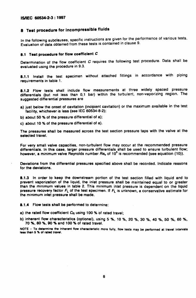
8 Test procedure for Incompressible fluids
In the following subclauses, specific instructi~ns are .give~ for the performance of various tests.Evaluat ion of data obtained from these tests IS contained In clause 9.
1 .1 Te.t procedure for flow coefficient C
Determination of the flow coefficient C requires the following test procedure. Data shall beevaluated using the procedure in 9.3.
1.1.1 Install the test specimen without attached fittings in accordance with pipingrequirements in table 1.
1.1.2 Flow tests shall include flow measurements at three widely spaced pressuredifferentials (but not less than 0,1 bar) within the turbulent, non-vaporizing region. Thesuggested differential pressures are
a) just below the onset of cavitation (incipient cavitation) or the maximum available in the testfacility, whichever is less (see lEe 60534-8-2);
b) about 50 % of the pressure differential of a);
c) about 10 % of the pressure differential of a).
The pressures shall be measured across the test section pressure taps with the valve at theselected travel.
For very small valve capacities, non-turbulent flow may occur at the recommended pressuredifferentials. In this case, larger pressure differentials shall be used to ensure turbulent flow;however, a minimum valve Reynolds number RSy of 105 is recommended (see equation (10».
Deviations from the differential pressures specified above shall be recorded. Indicate reasonsfor the deviations.
1.1.3 In order to keep the downstream portion of the test section filled with liquid and toprevent vaporization of the liquid, the inlet pressure shall be maintained equal to or greaterthan the minimum values in table 2. This minimum inlet pressure is dependent on the liquidpressure recovery factor FL of the test specimen. If FL is unknown, a conservative estimate forthe minimum inlet pressure shall be made.
1.1.4 Flow tests shall be performed to determine:
a) the rated flow coefficient CR using 100 % of rated travel;
b) inherent flow characteristics (optional), using 5 %, 10 %, 20 %, 30 %, 40 %, 50 % , 60 %,70 %, 80 %, 90 '" and 100 % of rated travel.
NOTE - To determine the inherent now characteristic more fully, flow tests may be performed at trayel IntervalsIns than 5 "'" of rated travel.
8
ISIIEC 80534-2-3: 1117
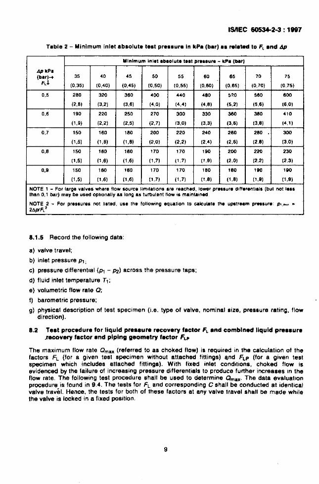
Table 2 - Minimum inlet absolute test pressure In kPa (bar) as related to Fl and 4p
Minimum Inl.t ab.olut. t••t pre••ure - kPa (bar)
I1p kPa(bar)... 35 40 45 50 55 60 65 70 75
FlJ. (0,35) (0,40) (0,45) (0,50) (0,55) (0,60) (0,65) (0,70) (0.75)
0,5 280 320 360 400 440 480 5~0 560 600
(2,8) (3,2) (3,6) (4,0) (4,4) (4,8) (5,2) (5.6) (6.0)
0,6 190 220 250 270 300 330 360 380 4'0
(1,9) (2,2) (2,5) (2,7) 13,0) (3,3) (3,6) (3,8) (4.')
0,7 150 160 180 200 220 240 260 280 300
(1,5) (1,6) (1,8) (2,0) (2,2) (2,4) (2,6) (2.8) (3,0)
0,8 150 160 160 170 170 190 200 220 230
(1,5) (1,6) (1,6) (1,7) (1,7) (1.9) (2,0) (2,2) (2,3)
0,9 150 160 160 170 170 180 180 190 190
(1,5) (1,6) (1,6) (1,7) (1,7) (',8) (1,8) (1,9) (1,9)
NOTE 1 - For large valves where flow source limitations are reached, lo_r pr...ure diff.renllals (but not le.sthan 0,1 bar) may be used optionally as long as turbulent flow is maIntained.
NOTE 2 - For pressures not listed, use the following equation to calculate the upstream prnsure: ", ,mm a
2AplFL 2
8.1.5 Record the following data:
a) valve travel;
b) inlet pressure Pl;
c) pressure differential (Pl - 1'2) across the pressure taps;
d) fluid inlet temperature Tl;
e) volumetric flow rate 0;
f) barometric pressure;
g) physical description of test specimen (i.e. type of valve. nominal size. pressure rating, flowdirection).
8.2 Teat procedure for liquid preaaure recovery fector FL end combined liquid preaaure.recovery fector and piping geometry factor FLJI
The maximum flow rate Omax (referred to as choked flow) is required in the calculation of thefactors FL (for a given test specimen without attached fittings) ,nd FLP (for a given testspecimen which includes attached fittings). With fixed inlet conditions. choked flow isevidenced by the failure of increasing pressure differentials to produce further increases in theflow rate. The following test procedure shall be used to determine Omax' The data evaluationprocedure is found in 9.4. The tests for FL and corresponding C shall be conducted at identicalvalve travel. Hence, the tests for both of these factors at any valve travel shall be made whilethe valve is locked in a fixed position.
9
ISIIEC 60534-2-3: 1997
8.2.1 The test section of 5.2 shall be used with the test specimen locked at the des ired
pos ition .
8.2.2 The downstream throttl ing valve shall be in the wide -open position. With a preselectedinlet pressure. the flow rate shall be measured and the inlet and outlet pressure,s rec~rde~ .This test establ ishes the max imum pressure differential (P1 - P2) for the test spec imen In thistest system. With the same inlet pressure, a second test shall ~e co.nducte~ with the pressuredifferential reduced to 90 % of the pressure differential determined In the first test. If the flowrate in the second test is within 2 % of the flow rate in the first test , the flow rate measured inthe first test may be taken as Qmax '
If not, repeat the test procedure at a higher inlet pressure. If Q max cannot be achieved at thehighest inlet pressure for the test system , use the following procedure. Calculate a value of FLsubstituting the flow rate obtained at max imum obtainable values of inlet pressure andpressure differential. For the valve under test. report that FL is greater than the valuecalculates as described in the previous sentence.
8.2.3 Record the following data :
a) valve trave l;
b) inlet pressure P1;
c) outlet pressure P2;
d) fluid inlet temperature T1 ;
e) volumetric flow rate Q;
f) barometric pressure;
g) physical description of test spec imen (i.e . type of valve , nominal size , pressure rat ing , flowdirection).
8.3 Teat procedure for piping geometry factor Fp
The pip ing geometry facto r modifies the valve flow coefficient C for fittings attached to thevalve . The factor Fp is the ratio of C for a valve installed with attached fittings to the rated C ofthe valve installed without attached fitt ings and tested under identical service conditions . Toobtain this factor, replace the valve with the des ired combination of valve and attached fittings.Conduct flow tests according to 8.1 treating the combination as the test specimen for thepurpose of determining test section pipe size . For example, a ON 100 valve between a reducerand an expander in a ON 150 line would use pressure tap locations based on a ON 150 line.
The data evaluation procedure is found in 9.5 .
1.4 Tnt procedur. for liquid critical pr•••ure ratio factor FF
The liquid critical pressure ratio factor FF is almost exclusively a property of the fluid and itstemperature. It is the ratio of the apparent vens contracts pressure at choked flow conditions tothe vapour pressure of liquid at inlet temperature:
The quantity of FF may be determined experimentally by using a test specimen for which FLand C are known. The valve without attached fittings is installed in accordance with the pipingrequirements in table 1. The test procedure outlined in 8.2 for obtaining Qmax shall be usedwith the fluid of interest as the test fluid .
The data evaluation procedure is found in 9.6.
10

ISIIEC 60534-2-3: 1"7
8.5 Telt procedure for Reynolds number factor F,. for Incompre.alble flow
To produce values of the Reynolds number factor FR' non-turbutent flow condmons shall beestablished through the test valve . Such conditions will requ ire low pressure differentIals, highviscosity fluids, small values of C, or some combination of these. With the exception of valveswith very small values of C, turbulent flow will always exist when flowing tests are perlormed inaccordance with the procedure outlined in 8.1, and FR under these conditions will have thevalue of 1,0.
Determine values of FA by carrying out flowing tests with the valve Installed In the standard testsection without attached fittings . These tests should follow the procedure for C determinationexcept that
a) test pressure differentials may be any appropriate values provided that no vaporization ofthe test fluid occurs within the test valve;
b) min imum upstream test pressure values shown in table 2 may not apply if the test fluid isnot fresh water at 20°C ± 14 °C;
c) the test fluid should be a Newtonian fluid having a viscosity considerably greater than that ofwater unless instrumentation is available for accurately measuring very low pressuredifferentials .
Carry out a sufficient number of tests at each selected valve travel by varying the pressuredifferential across the valve so that the entire range of conditions , from turbulent to laminarflow, is spanned.
The data evaluation procedure is given in 9.7.
8.6 Telt procedure for valve style modifier Fd
The valve style modifier takes into account the effect of trim geometry on the Reynoldsnumber. It is defined as the ratio of the hydraulic diameter of a single flow passage to thediameter of a circular orifice, the area of which is equivalent to the sum of areas of al/ idenhcalflow passages at a given travel.
The value of Fd should be measured at the des ired travels . This value can only be measuredwhen fully laminar flow is obtained using the test procedure outlined in 8.5 .
Fully laminar flow is defined as a condition where JR6v I~ is constant with a ±5 % tolerance
range (typically with Rev values below 50) .
The data evaluation procedure is given in 9.8 .
9 Data evaluation procedure for Incompressible fluids
9.1 Non-choked flow
The basic flow equation for non-choked, incompressible fluids is:
(1)
For a valve installed without attached fitt ings, Fp .. 1, and for turbulent flow conditions, FA .. 1.
11
ISIIEC 60534-2-3: 1997
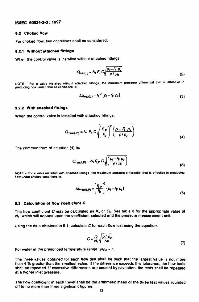
9.2 Choked flow
For choked flow, two conditions shall be considered:
9.2.1 Without attached fittings
When the control valve is installed without attached fittings:
(2)
NOTE _ For a valve installed without attached fittings. the maximum pressure differential that is effective inproducing flow under choked conditions is:
(3)
9.2.2 With attached fittings
When the control valve is installed with attached fittings:
( )
2flp P, -fl: Pv
Omax(LP) = N1 Fp C Fp
(PI AI )
The common form of equation (4) is:
J(PI-5= Pv)Qnu(LP) =~ FLp C PI Po
(4)
(5)
NOTE - For a valve installed with attached fittings. the maximum pressure differential that is effective in producingflow under choked conditions is:
AAnax(LP) =(4;-r(PI - 5= Pv)
9.3 Calculation of flow coefficient C
(6)
The flow coefficient C may be calculated as Kv or Cy. See table 3 for the appropriate value ofNl. which will depend upon the coefficient selected and the pressure measurement unit.
Using the data obtained in 8.1, calculate C for each flow test using the equation:
(7)
For water in the prescribed temperature range, plPo =1.
The three values obtained for each flow test shall be such that the largest value is not morethan 4 % greater than the smallest value. If the difference exceeds this tolerance. the flow testsshall be repeated. If excessive differences are caused by cavitation, the tests shall be repeatedat a higher inlet pressure.
The flow coefficient at each travel shall be the arithmetic mean of the three test values roundedoff to no more than three significant figures.
12
ISIIEC 60534-2-3: '117
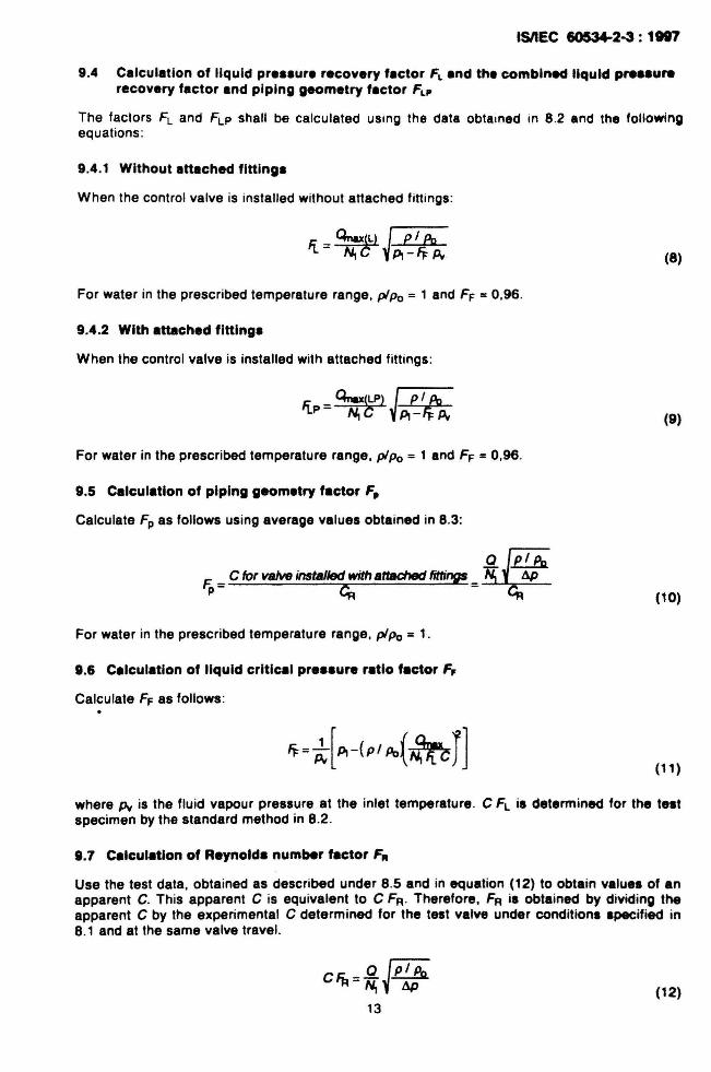
9.4 Calculation of liquid pre••ure recovery f.ctor FL and the combined liquid pre..urerecovery factor and piping geometry factor FLP
The factors Fl and FlP shall be calculated usrng the data obtarned in 8 .2 and the followingequations :
9.4.1 Without attached fitting.
When the control valve is installed without attached fittings:
(8)
For water in the prescribed temperature range, plPo = 1 and FF = 0,96.
9.4.2 With attached fitting.
When the control valve is installed with attached fittings:
(9)
For water in the prescribed temperature range. plPo = 1 and FF = 0,96.
9.5 Calculation of piping geometry factor F,.
Calculate Fp as follows using average values obtained in 8.3:
*J~/PoF._ C for valve installed with attached fittings _ &p
p- c:;:;
For water in the prescribed temperature range, plPo = 1.
9.6 Calculation of liquid critical pre••ure ratio factor F,
Calculate FF as follows:
~= ~[~-(PIPo(~rJ
(10)
(11 )
where Pv is the fluid vapour pressure at the inlet temperature. C FL is determined for the te.tspecimen by the standard method in 8.2.
9.7 Calculation of Reynold. number factor FA
Use the test data, obtained as described under 8.5 and in equation (12) to obtain value. of anapparent C. This apparent C is equivalent to C FR. Therefore. FR i. obtained by dividing theapparent C by the experimental C determined for the test valve under conditions specified in8.1 and at the same valve travel.
(12)
ISIIEC 60534-2-3: 1997
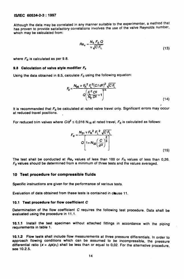
Although the data may be correlated in any manner suitable to the experimenter, a method thathas proven to provide sat isfactory correlations involves the use of the valve Reynolds number,which may be calculated from :
(13)
where Fd is calculated as per 9.8.
9.8 Calculation of valve style modifier Fd
Using the data obtained in 8.5, calculate Fd using the following equation:
(14)
It is recommended that Fd be calculated at rated valve travel only. Significant errors may occurat reduced travel positions.
For reduced trim valves where c/c1 s 0,016 N18 at rated travel , Fd is calculated as follows :
Fd
= N31 vFFl11.2~
a['+N32( ;' ) ' ]
(15)
The test shall be conducted at Rev values of less than 100 or FR values of less than 0,26.Fd values should be determined from a minimum of three tests and the values averaged.
10 Test procedure for compressible fluids
Specific instructions are given for the performance of various tests .
Evaluation of data obtained from these tests is contained in cause 11.
10.1 Test procedure for flow coefficient C
Determination of the flow coefficient C requires the following test procedure. Data shall beevaluated using the procedure in 11 .1 .
10.1.1 Install the test specimen without attached fittings in accordance with the pip ingrequirements in table 1.
10.1.2 Flow tests shall include flow measurements at three pressure differentials. In order toapproach flowing conditions which can be assumed to be incompressible, the pressuredifferential ratio (x =L1p1P1) shall be less than or equal to 0,02. For the alternative procedure,see 10.2.5.
14
ISIIEC 60534-2-3: 1997
10.1.3 Flow tests shall be performed to determine:
a) the rated flow coefficient C, using 100 % of rated travel ;
b) inherent flow characteristics (optional), using 5 %, 10 %, 20 %, 30 %, 40 %, 50 %, 60 %,70 %, 80 %, 90 % and 100 % of rated travel.
NOTE - To determine the inherent flow characteristics more fully, flow tests may be performed at travels less than5 % of rated travel.
10.1.4 Record the following data:
a) valve travel;
b) inlet pressure P1 ;
c) pressure differential (Pl - 1'2) across pressure taps;
d) fluid inlet temperature T1;
e) VOlumetric flow rate Q;
f) barometric pressure;
g) physical description of test specimen (i.e . type of valve, nominal size, pressure rating, flowdirection).
10.2 Test procedure for pressure differential ratio factors JeT and JeTP
The quantities Xl" and Xl"P are the terminal ratios of the differential pressure to absolute inletpressure (t!plpl) for fluids with Fy = 1 (y = 1,4). However, these quantities can be obtainedwhen using test gases for which Fy does not equal 1 as shown in equations (23) and (24). Themaximum flow rate Qmax (referred to as choked flow) is required in the calculation of Xl" (for agiven test specimen without attached fittings) and Xl"P (for a given test specimen with attachedfittings). With fixed inlet conditions, choked flow is evidenced by the failure of increasingpressure differentials to produce further increases in the flow rate. Values of Xr and Xl"P shallbe calculated using the procedures in 11.2 and 11.3, respectively.
The following test procedure shall be used to determine Qmax'
10.2.1 The test section of 5.2 shall be used, with the test specimen at 100 % of rated travel.
10.2.2 Any upstream supply pressure sufficient to produce choked flow is acceptable, as isany resulting pressure differential across the test specimen provided the criteria of choked flow(specified in 10.2.3) are met.
10.2.3 The downstream throttling valve shall be in the wide-open position. With a preselectedinlet pressure, the flow rate shall be measured and the inlet and outlet pressures recorded.This test establishes the maximum pressure differential (Pl - 1'2) for the test specimen in thistest system. Using the same inlet pressure, a second test shall be conducted with the pressuredifferential reduced to 90 % of the pressure differential determined in the first test. If the flowrate of this second test is within 0,5 % of the flow rate for the first test, the flow rate measuredin the first test may be taken as Qmax. If not, repeat the test procedure at a higher inletpressure.
Although the absolute value of the flow rate shall be measured to an error not exceeding ±2 %,the repeatability of the tests for JlT shall be better than ±O,5 % in order to attain the prescribedaccuracy. This series of tests shall be made consecutively, using the same instruments. andwithout alteration to the test set-up.
15
ISIIEC 60534-2-3: 1997
10.2.4 Record the following data:
a) valve travel;
b) inlet pressure Pl;
c) outlet pressure P2;
d) fluid inlet temperature T1;
e) volumetric flow rate Q;
f) barometric pressure;
g) physical description of test specimen (i.e. type of valve, nominal size, pressure rating, flowdirection).
10.2.5 Alternative test procedure for pressure differential ratio factors xT and xTP
and flow coefficient C
If a laboratory is unable to determine the Xy value for a valve using the procedure describedabove, this alternative procedure may be used.
The test section of 5.2 shall be used with the test specimen at 100 % of rated travel.
With a preselected inlet pressure, measurements shall be made of flow rate Q, fluid inlettemperature T, and downstream pressure for a minimum of five well-spaced values of x (theratio of pressure differential to absolute inlet pressure).
From these data points, calculate values of the product Y C using the equation:
YC==~iMT,NaP! x
where Y is the expansion factor defined by:
(16)
Y == 1
in which Fy =r /1 ,4.
x
(17)
The test points shall be plotted on linear coordinates as (Y C) versus x and a linear curve fittedto the data. If any point deviates by more than 5 % from the curve, additional test data shall betaken to ascertain that the specimen truly exhibits anomalous behaviour.
The value of Co for the specimen shall be taken from the curve at x = 0, Y = 1.
At least one test point (Y C)1 shall fulfill the requirement that (Y C)1 ~ 0,97 (Y C)O, where(Y C)O corresponds to x =O.
At least one test point (Y C)n shall fulfill the requirement that (Y C)n S 0,83 (Y C)o'
The value of Xy for the specimen shall be taken from the curve at (Y C) == 0,667 (Y C)O.
If this method is used, that fact shall be stated.16
ISIIEC 60534-2-3: 1997
10.3 Test procedure for piping geometry fector Fp
The piping geometry factor modifies the valve flow coefficient C for fittings attached to thevalve. The factor Fp is the ratio of C for a valve installed with attached fittings to the rated C ofthe valve installed without attached fittings and tested under identical service conditions.
To obtain this factor, replace the valve with the desired combination of valve and attachedfittings. Then conduct the flow tests according to 10.1 treating the combination as the testspecimen for the purpose of determining test section pipe size. For example, a ON 100 valvebetween a reducer and expander in a ON 150 line would use pressure tap locations based on aON 150 line.
The data evaluation procedure is given in 11.4.
10.4 Test procedure for Reynolds number fector FR
To establish values of the Reynolds number factor FA, non-turbulent flow conditions shall beestablished through the test valve. Such conditions will typically only occur, using compressiblefluid, if the CR value is less than D,S for Cv or 0,43 for Ky.
Non-turbulent flow conditions are deemed to exist when, using the procedure outline in 10.2,the amount of gas flow measured is still increasing even though x ~ ~ for the specific valve.i.e., there is no choked flow.
In order to obtain such non-turbulent flow, the inlet pressure to the test specimen should beless than:
(18)
in bar, but no less than 2 bar absolute.
Determine values of FA by carrying out flow tests with the valve installed in the standard testsection without attached fittings. Carry out a sufficient number of tests at each selected valvetravel by varying the inlet pressure so that the entire range from turbulent to laminar flow isspanned.
The data evaluation procedure is given in 11.5.
10.5 Test procedure for velve style modifier Fd
The valve style modifier accounts for the effect of trim geometry on the Reynolds number. It isdefined as the ratio of the hydraulic diameter of a specific flow passage to the equ ivalentcircular diameter of the total flow area.
The value of Fd should be measured at the desired travels. This value can only be measuredwhen fully laminar flow is obtained using the test procedure given in 8.5 .
Fully laminar flow is defined as a condition where JRe y I Fr is constant with a ±5 % tolerance
range (typically with RBy values below 50) .
The data evaluation procedure is given in 11.6.
17
ISIIEC 60534-2-3: 1997
10.6 Test procedure for small flow trim
Trim having a flow coefficient C less than 0,05 for Cv (0,043 for Ky ) is defined as s":,all flowtrim. To ensure that the flow coefficient C for small flow trim is fully in the turbulent regime. theinlet pressure p, should be no less than the value given in the following equation:
(19)
where the outlet pressure is less than 0.3 Pl. The test section of 5.2 shall be used with the testspecimen at 100 % of rated travel. With constant inlet pressure, vary the outlet pressure toobtain three separate flow rates.
The data evaluation procedure is given in 11.7.
11 Data evaluation procedure for compressible fluids
The basic flow equation for compressible fluids is:
(20)
where
(21)
in which Fy = y1,4.
For flow tests where no fittings are attached to the valve, Fp = 1.
For a control valve handling a gas different from air, the terminal value of x (i.e ., Fy x-r) shall becorrected in the term Fy x-r. The value of x used in any of the sizing equations or therelat ionship for Y shall be held to this limit even though the actual pressure differential ratio isgreater. In practice the numerical value of Y will range from almost one for very low differentialpressures to 0,667 for choked flow (x = Fy x-r).
11.1 Calculation of flow coefficient C
The flow coefficient C may be calculated as Ky or Cv. See tab le 3 for the appropriate value ofNg which will depend upon the coefficient selected and the inlet pressure measurement unit.
Using the data obtained in 10.1 and assuming that Y = 1, calculate the flow coefficient C foreach test point using:
(22)
For air, M = 28 ,97 kglkmol.
18
ISIIEC 60534-2-3: 1997
Annex A(normative)
Typical examples of test specimens showingappropriate pressure tap locations
Flow
a) Control valve
60
b) Control valve with reducer and expander
o
I 20• ·1
I·
c) Control valve with elbows
60
o
d) Control valve with by-pass
60
MGIPF-777 D<ptt fo BI512001-25 102001-300 Boob21

ISIIEC 60534-2-3: 1997
Indian StandardINDUSTRIAL-PROCESS CONTROL VALVES
PART 2 FLOW CAPACITYSection 3 Test Procedures
1 Scope
This section of IEC 60534-2 is applicable to industria l-process control valves and provides theflow capacity test procedures for determining the following variables used in the equationsgiven in IEC 60534-2-1 and IEC 60534-2-2:
a) flow coefficient C;
b) liquid pressure recovery factor without attached fittings FL;
c) combined liquid pressure recovery factor and piping geometry factor of a control valve withattached fittings FLP;
d) piping geometry factor Fp;
e) pressure differential ratio factors XT and XTp;
f) valve style modif ier Fd ;
g) Reynolds number factor FR.
2 Normative references
The following normative documents contain prov isions which, through reference in th is text,constitute provisions of this section of IEC 60534-2. At the time of publication, the editionsindicated were val id. All normative documents are subject to revision, and parties toagreements based on this section of IEC 60534-2 are encouraged to investigate the possibil ityof applying the most recent editions of the normative documents indicated below. Members ofIEC and ISO maintain registers of currently valid International Standards.
IEC 60534-1:1987, Industrial-process control valves - Part 1: Control valve terminology andgeneral considerations
IEC 60534-2:1978, Industrial-process control valves - Part 2: Flow capacity - Section One:Sizing equations for incompressible fluid flolN under installed conditions
IEC 60534-2-2:1980, Industrial-process control valves - Part 2: Flow capacity - Section Two:Sizing equations for compressible fluid flow under installed conditions
IEC 60534-8-2:1991. Industrial-process control valves - Part 8: Noise considerations Sect ion 2 : Laboratory measurement of noise generated by hydrodynamic flow through controlvalves
IEC 61298-1 :1995 , Process measurement and control devices - General methods andprocedures for evaluating performance - Part 1: General considerations
IEC 61298-2:1995, Process measurement and control devices - General methods andprocedures for evaluating performance - Part 2 : Tests under reference conditions
ISIIEC 60534-2-3: 1997
3 Definitions
For the purpose of this section of lEG 60534-2, the definitions given in lEG 60534-1,lEG 60534-2, lEG 60534-2-2 , lEG 61298-1, and lEG 61298-2 apply.
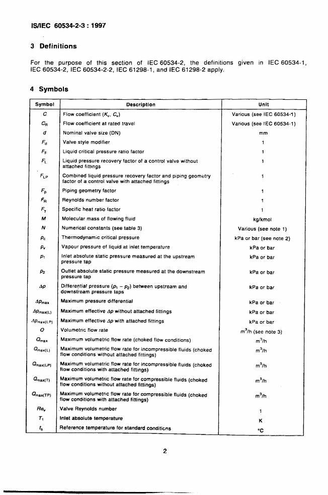
4 Symbols
Symbol Description Unit
C Flow coefficient (Ky , Cy ) Various (see IEC 60534-1)
CA Flow coefficient at rated travel Various (see IEC 60534-1)
d Nominal valve size (ON) mm
F d Valve style modifier 1
FF Liqu id critical pressure ratio factor 1
Fl Liquid pressure recovery factor of a control valve without 1attached filtings
F l P Combined liquid pressure recovery factor and piping geom<Jtry 1factor of a control valve with attached fitt ings
Fp Pip ing geometry factor 1
FA Reynolds number factor 1
F1 Specific heat ratio factor 1
M Molecular mass of flowing fluid kg/kmol
N Numerical constants (see table 3) Various (see note 1)
Pc Thermodynamic critical pressure kPa or bar (see note 2)
p; Vapour pressure of liquid at inlet temperature kPa or bar
PI Inlet absolute static pressure measured at the upstream kPa or barpressure tap
P2 Outlet absolute static pressure measured at the downstream kPa or barpressure tap
lip Differential pressure (PI - P2) between upstream and kPa or bardownstream pressure taps
liPmax Maximum pressure differential kPa or bar
liPmax(ll Maximum effective lip without attached fittings kPa or bar
liPmax(lPI Maximum effective lip with attached fitt ings kPa or bar
0 Volumetric flow rate m3/h (see note 3)
Omax Maximum volumetric flow rate (choked flow conditions) m3/h
Omax(ll Maximum volumetric flow rate for incompressible flu ids (choked m3/h
flow conditions without attached fittings)
Omax(lP) Maximum volumetric flow rate for incompressible fluids (choked m3/h
flow conditions with attached fittings)
Omax(T) Maximum volumetric flow rate for compressible fluids (choked m3/h
flow conditions without attached fittings)
Omax(TPI Maximum volumetric flow rate for compressible fluids (choked m3/h
flow conditions with attached fitt ings)
Rev Valve Reynolds number 1TI Inlet absolute temperature K
t. Reference temperature for standard conditions ·C
2

(Continued from second cover)
International Standard Title
IEC 61298-2 : 1995 Process measurement and control devices - General methods andprocedures for evaluating performance - Part 2: Test under referenceconditions '
Only the English language text in the International Standard has been retained while adopting it in thisIndian Standard, and as such the page numbers given here are not the same as in the lEG Standard.
For the purpose of deciding whether a particular requirement of this standard is complied with, thefinal value, observed or calculated, expressing the result of a test or analysis, shall be rounded off inaccordance with IS 2 : 1960 'Rules for rounding off numerical values (revised)' . The number ofsignificant places retained in the rounded off value should be same as that of the specified value inthis standard.
Bureau of Indian Standards
BIS is a statutory institution established under the Bureau of Indian Standards Act, 1986 to promoteharmonious development of the activities of standardization, marking and quality certification of goodsand attending to connected matters in the country.
Copyright
BIS has the copyright of all its publications. No part of these publications may be reproduced in anyform without the prior permission in writing of BIS. This does not preclude the free use, in course ofimplementing the standard, of necessary details, such as symbols and sizes, type or gradedesignations. Enquiries relating to copyright be addressed to the Director (Publications), BIS.
Review of Indian Standards
Amendments are issued to standards as the need arises on the basis of comments. Standards arealso reviewed periodically; a standard along with amendments is reaffirmed when such reviewindicates that no changes are needed; if the review indicates that changes are needed, it i6 taken upfor revision. Users of Indian Standards should ascertain that they are in possession of the latestamendments or edition by referring to the latest issue of 'BIS Catalogue' and 'Standards: MonthlyAdditions'.
This Indian Standard has been developed from Doc: No. ETD 18 (5673).
Amendments Issued Since Publication
Amendment No. Date of Issue
BUREAU OF INDIAN STANDARDS
Text Affected
tfeadquarters:
Manak Bhavan, 9 Bahadur Shah Zafar Marg, New Delhi 110 002Telephones: 23230131,23233375,23239402 Website: www.bis.org.in
Regional Offices:
Central: Manak Bhavan, 9 Bahadur Shah Zafar MargNEW DELHI 110 002
Telephones
{2323761723233841
Eastern: 1/14, C.I.T. Scheme VII M, V.I.P. Road, KankurgachiKOLKATA 700 054
Northem: SCO 335-336, Sector 34-A, CHANDIGARH 160 022
Southem: C.I.T. Campus, IV Cross Road, CHENNAI600 113
Western: Manakalaya, E9 MIDC, Marol, Andheri (East)MUMBAI 400 093
{23378499,233785612337 8626, 2337 9120
{260 3843260 9285
{2254 1216, 2254 144222542519,2254 2315
{28329295,283278582832 7891, 2832 7892
Branches: AHMEDABAD. BANGALORE. BHOPAL. BHUBANESHWAR. COIMBATORE. FARIDABAD.GHAZIABAD. GUWAHATI. HYDERABAD. JAIPUR. KANPUR. LUCKNOW. NAGPUR.PARWANOO. PATNA. PUNE. RAJKOT. THIRUVANANTHAPURAM. VISAKHAPATNAM.
Printed by the Manager. Govt. of India Press. Faridabad