isiteprofessional users guide-en - meritech professional users... · meritech co., ltd. and the...
TRANSCRIPT

1
USER’S GUIDE
201 Pastoral Shinyurigaoka
1-8-7 Manpukuji, Asao-ku
Kawasaki City, Kanagawa
Japan 215-0004

2
iSite Professional User’s Guide
Copyright 2004-2008 Meritech Co., Ltd. All rights reserved.
Information in this document is subject to change without notice and does not represent a
commitment on the part of the vendor or its representatives. No part of this document shall
be reproduced, stored in a retrieval system, or transmitted by any means, electronic, mechanical, photo-copying, recording, or otherwise, without written permission from
Meritech Co., Ltd. No patent liability is assumed with respect to the use of the information
contained herein. Although every precaution has been taken in the preparation of this book, Meritech Co., Ltd. and the author assume no responsibility for errors or omissions. Neither is
any liability assumed for damages resulting from the use of the information contained herein.
Company Headquarters:
201 Pastoral Shinyurigaoka 1-8-7 Manpukuji, Asao-ku
Kawasaki City, Kanagawa
Japan 215-0004
Tel: +81 (0) 44-953-0967
Fax: +81 (0) 44-953-0968
Customer Support:
201 Pastoral Shinyurigaoka
1-8-7 Manpukuji, Asao-ku Kawasaki City, Kanagawa
Japan 215-0004
Tel: +81 (0) 44-953-0967
Fax: +81 (0) 44-953-0968
E-mail: [email protected]
For further information, please visit our web site at: http://www.MeritechSolutions.com

Contents
3
T A B L E O F C O N T E N T S
Preface ................................................................................................................................. 5 Document Overview.......................................................................................................... 5 Conventions used in the Guide ......................................................................................... 6 List of Abbreviations......................................................................................................... 6
Chapter 1 ............................................................................................................................... 7 Introduction.......................................................................................................................... 7
Chapter Overview............................................................................................................. 7 Microcell etwork Survey and Design ............................................................................. 7
Chapter 2 ............................................................................................................................... 8 iSite Professional Features................................................................................................... 8
Chapter Overview............................................................................................................. 8 Layered Architecture ........................................................................................................ 8
Design Elements Layers ................................................................................................ 9 Result Layers ................................................................................................................. 9
Workspace Elements......................................................................................................... 9 Menu Bar ....................................................................................................................... 9 Tool Bar....................................................................................................................... 15 Status Bar .................................................................................................................... 17 Project Explorer........................................................................................................... 18 Layers View................................................................................................................. 18 Materials View ............................................................................................................ 19 Transceivers View ....................................................................................................... 19 Antenna Pattern View.................................................................................................. 20 Properties View ........................................................................................................... 20 Information View ........................................................................................................ 21 Measurement View...................................................................................................... 22 Spectrum View ............................................................................................................ 23 Floor Plan Design Surface ........................................................................................... 23
Customizing Workspace.................................................................................................. 24 Full Screen View ......................................................................................................... 24 Showing and Hiding Toolbars..................................................................................... 24 Zoomed View .............................................................................................................. 24
Other Features................................................................................................................ 24 Clipboard Functionality............................................................................................... 24 Undo-Redo Buffer ....................................................................................................... 25 File Types .................................................................................................................... 25
Chapter 3 ............................................................................................................................. 26 Using iSite for Survey........................................................................................................ 26
Chapter Overview........................................................................................................... 26 Starting a ew Project.................................................................................................... 26 Preparing to Survey........................................................................................................ 28 Survey the etwork ......................................................................................................... 31 View the etwork Performance ...................................................................................... 31
Chapter 4 ............................................................................................................................. 35 Using iSite for Design........................................................................................................ 35
Chapter Overview........................................................................................................... 35

Contents
4
Starting a ew Project.................................................................................................... 35 Preparing to Design ....................................................................................................... 37 Creating the Designing................................................................................................... 40 Optimizing the Designing ............................................................................................... 40
Chapter 5 ............................................................................................................................. 43 Using iSite in Mixed Mode................................................................................................ 43
Chapter Overview........................................................................................................... 43 Mixed Mode Overview.................................................................................................... 43 Starting a ew Project.................................................................................................... 43 Getting the Mixed Mode Results ..................................................................................... 45
Chapter 6 ............................................................................................................................. 49 Configuring Components................................................................................................... 49
Chapter Overview........................................................................................................... 49 Configuring Layers......................................................................................................... 49 Configuring Results ........................................................................................................ 50 Configuring Design Elements......................................................................................... 51 Configuring Materials .................................................................................................... 52 Configuring Transceivers ............................................................................................... 54 Configuring Antenna Patterns ........................................................................................ 56 Configuring Project Properties ...................................................................................... 58
Chapter 7 ............................................................................................................................. 61 Using Reports .................................................................................................................... 61
Chapter Overview........................................................................................................... 61 Opening Report Dialog................................................................................................... 61 Generate Report in Survey Mode.................................................................................... 61 Generate Report in Design Mode ................................................................................... 63
Appendix A .......................................................................................................................... 66 Setup iSite Professional ..................................................................................................... 66
Appendix Overview......................................................................................................... 66 System Requirements ...................................................................................................... 66 Installing iSite Professional............................................................................................ 66 Updating iSite Professional ............................................................................................ 71 Uninstalling iSite Professional ....................................................................................... 71
Index..................................................................................................................................... 72

Preface
5
Welcome to iSite Professional, an application used to survey and design WiFi networks. The
iSite application is a computer aided design (CAD) application. It allows the network coverage to be visualized before and after hardware is installed. The design can be easily
adjusted to optimize coverage and minimize interference.
Document Overview The iSite Professional User’s Guide details the features, functions, and use of iSite
Professional .
This guide is divided into the following chapters.
• Chapter 1, Introduction
This chapter gives an introduction to iSite Professional .
• Chapter 2, iSite Professional Features
This chapter describes the iSite Professional workspace, its basic elements, and file
types.
• Chapter 3, Using iSite Professional Survey
This chapter lists and explains the steps required to configure iSite Professional in
survey mode and create a basic design.
• Chapter 4, Using iSite Professional Design
This chapter lists and explains the steps required to configure iSite Professional in design mode, create a basic design, and optimize it.
• Chapter 5, Using iSite Professional Mixed Mode
This chapter lists and explains the steps required to configure iSite Professional in mixed mode and create a basic mixed plot.
• Chapter 6, Configuring Components
This chapter lists and explains the steps required to configure elements used in an iSite
Professional project.
• Chapter 7, Using Reports
This chapter lists and explains the steps required to view Reports in an iSite
Professional project.
• Appendix A, Installing iSite Professional
This appendix describes the sequence of steps to install and uninstall iSite Professional.
Preface
Preface
6
Conventions used in the Guide
Listed are the various typographical conventions followed throughout this guide:
[Enter]: Square brackets denote specific keys or buttons on the keyboard.
Italics: Indicates file names.
Bold Italics: Indicates screen names that appear on the title bar of User Interface (UI)
screens.
Bold: Indicates names of menus, options, sub-options appearing in the UI, and field names
appearing on UI screens.
� : Indicates that a note about the preceding information follows.
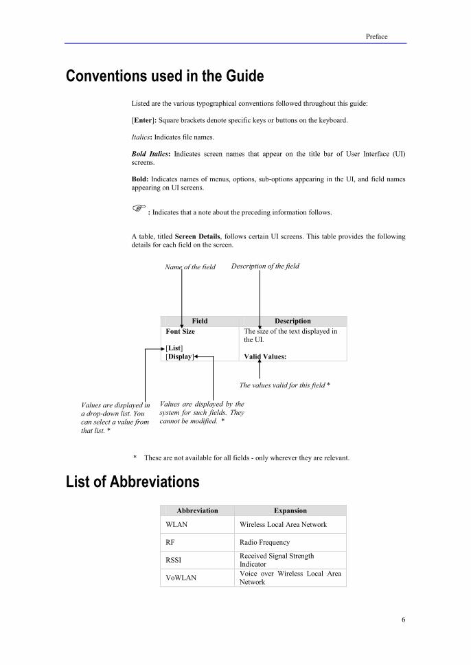
A table, titled Screen Details, follows certain UI screens. This table provides the following details for each field on the screen.
Field Description
Font Size
[List]
[Display]
The size of the text displayed in
the UI.
Valid Values:
* These are not available for all fields - only wherever they are relevant.
List of Abbreviations
Abbreviation Expansion
WLAN Wireless Local Area Network
RF Radio Frequency
RSSI Received Signal Strength Indicator
VoWLAN Voice over Wireless Local Area
Network
Values are displayed in a drop-down list. You
can select a value from
that list. *
Values are displayed by the
system for such fields. They
cannot be modified. *
The values valid for this field *
ame of the field Description of the field

Chapter 1 Introduction
7
C H A P T E R 1
This chapter introduces iSite Professional defining its overall purpose.
Chapter Overview The following points are explained in this chapter.
• Microcell Network Survey and Design
Microcell Network Survey and Design iSite Professional is a microcell network survey and design application. It was created for
microcell networks such as WLAN and other technologies with coverage areas of radius between 10 and 500 meters.
iSite Professional can be used in three modes, survey, design and mixed. In the survey mode, iSite Professional records measurement points in an existing network and shows the
coverage. In the design mode, iSite Professional is used to design a network before hardware
is installed. Mixed mode is the combination of design and survey modes. It can design a network along with recording measurement points in the existing network.
iSite Professional accelerates the process of WLAN design and simplifies network management. It was created for IT professionals who struggle with the complexities of
WLAN deployment. Requiring minimal knowledge of Radio Frequency (RF) engineering,
iSite Professional implements an easy to use windows interface and fast RF propagation engine. iSite Professional helps visualize the network before installation begins so that IT
professionals can adjust the network configuration to maximize coverage and minimize
interference. Network security is also improved by controlling excessive coverage. iSite Professional provides the best solution for WLAN deployment and management.
Introduction

Chapter 2 iSite Professional Features
8
C H A P T E R 2
This chapter introduces the architecture of iSite Professional and its workspace elements. The
workspace elements, such as menus, tool bars, and windows, are similar to most Microsoft
Windows applications. The iSite Professional workspace conforms to standard Microsoft Windows guidelines.
You can customize the iSite Professional workspace according to your preferences and requirements.
Chapter Overview The following points are explained in this chapter.
• Layered Architecture
• Workspace Elements
• Customizing Workspace
• Other Features
Layered Architecture iSite Professional provides a simple GUI to work upon, there are many elements which a user
can draw on a drawing board type surface to emulate it like a floor and can add as many
drawing surfaces as required to imitate it like a building with multiple floors. These drawing elements are called design elements. Various design elements provided by iSite Professional
are:
• Marker – This element is used to mark up a specific location on a floor for
proper alignment. When you add a marker on a floor plan it automatically gets drawn on the other floors for the symmetrical alignment.
• Image – This element allows you to add a drawing on the floor.
• Barrier – This element draws multiple lines on the floor to depict the barriers in
a network.
• Access Point – Emulates the Access Point to add on the floor.
• Floor Area – This element is used to add a specific type of material to a floor that may affect the coverage of the network.
• Security Area – To create a secure area for a floor.
• Measurement Point – This element is available with survey mode of the application and used to get the network coverage in its region.
• GPS Reference Point – This element is available with survey mode of the application and used to add GPS reference point on a floor.
• Comment – To add a comment box for a floor.
iSite Professional Features

Chapter 2 iSite Professional Features
9
Like design elements, iSite Professional provides some Result elements, such as coverage
and interference that displays the plots generated due to access points enabled in a building.
Design Elements Layers
Every design element is categorized in the form of layers. One can control the functionality
of a particular element by manipulating its associated layer or you can say that a layer describes the properties of the concerned element. For barriers a barrier layer is present, for
manipulating access points an access point layer is provided.
You need to select the concerned layer before manipulating elements, such as adding, editing
properties, or deleting them.
Result Layers
Like design element layers, every result element also has a corresponding result layer.
Selecting different results layers allows you to view different results or plots provided by
iSite Professional
Workspace Elements The iSite Professional workspace consists of the following workspace elements.
Menu Bar
iSite Professional displays a menu bar as shown in Figures 2.1.
Figure 2.1 Menu Bar
The menu bar consists of the following menus and their corresponding options.
File Menu
The File menu consists of the following options.

Chapter 2 iSite Professional Features
10
Figure 2.2 File Menu Options
• 8ew: This option creates a new project.
• Open: This option opens an existing project.
• Close: This option closes the current project.
• Save: This option saves the current project using the current project name.
• Save As: This option saves the current project using a different project name.
• Import: This option imports materials and transceivers from an XML file. It also lets you import access point configuration from a CSV file, which is exported through
Export->Access Point Configuration in iSite Professional . Lastly, there are options to
import measurement data for iSite Professional Format and Brew Format. The measurement data import will only import measurement point data. This is useful when
merging survey data into one project.
• Export: This option exports materials or transceivers to an XML file and the configuration of access points and measurement points to a CSV file. Access point
configuration can be exported in two formats. Measurement point information can be
exported based on following RSSI values:
o Median
o Maximum
o Minimum
o Average
Lastly, there is an option to export an iPoint Radio Map. This export option is used in conjunction with Meritech’s iPoint RTLS.
• Page Setup: This sets up the document configuration before printing.
• Print Preview: This option previews the document before printing.
• Print: This option prints the document.
• Recent Projects: This option is a list of previously opened projects. Choose a project to open it.
• Exit: This option exits the iSite Professional application.
Edit Menu
The Edit menu consists of the following options.
Figure 2.3 Edit Menu Options
• Undo: This option undoes the most recent edit operation.

Chapter 2 iSite Professional Features
11
• Redo: This option redoes the most recent edit operation that was undone.
• Cut: This option cuts the selected elements on the design surface.
• Copy: This option copies the selected elements on the design surface.
• Paste: This option pastes the current clipboard elements to the design surface.
• Delete: This option deletes the selected elements from the design surface.
• Copy Visible Area: This option copies the visible portion of the design surface area.
View Menu
The View menu consists of the following options.
Figure 2.4 View Menu Options
• Project Explorer: This option displays the Project Explorer view.
• Layers: This option displays the Layers view.
• Materials: This option displays the Materials view.
• Transceivers: This option displays the Transceivers view.
• Antenna Patterns: This option displays the Antenna Pattern view.
• Properties: This option displays the Properties view.
• Information: This option displays the Information view.
• Measurement: This option displays the Measurement view.
• Spectrum: This option displays the Spectrum view.
• Zoom: This option is used to set the zoom level of the design surface.
• Fit to Window: This option sets the zoom level so that the full design surface fits in the
current viewable window.
• Full Screen: This option changes the user interface to full screen mode.

Chapter 2 iSite Professional Features
12
• Refresh: This option recalculates the results and refreshes the result displays.
Project Menu
The Project menu consists of the following options.
Figure 2.5 Project Menu Options
• 8ew Floor Plan: This option adds a new floor plan to the project.
• Marker Layer: This option sets the Marker Layer as the active layer.
• Image Layer: This option sets the Image Layer as the active layer.
• Barrier Layer: This option sets the Barrier Layer as the active layer.
• Access Point Layer: This option sets the Access Point Layer as the active layer.
• Floor Area Layer: This option sets the Floor Area Layer as the active layer.
• Security Area Layer: This option sets the Security Area Layer as the active layer.
• Measurement Layer: This option sets the Measurement Layer as the active layer.
• GPS Reference Layer: This option sets the GPS Reference Layer as the active layer.
• Comment Layer: This option sets the Comment Layer as the active layer.
• Project Properties: This option opens the Project Properties dialog.
Tools Menu
The Tools menu consists of the following options.

Chapter 2 iSite Professional Features
13
Figure 2.6 Tools Menu Options
• Pointer: This option sets the Pointer Tool as the active tool.
• Rotation: This option sets the Rotation Tool as the active tool.
• Zoom: This option sets the Zoom Tool as the active tool.
• Measure Distance: This option sets the Measure Distance Tool as the active tool.
• Scale Image: This option sets the Scale Image Tool as the active tool.
• Add Element: This option sets the Add Element Tool as the active tool. The element
that is added depends on the active layer.
Result Menu
The Results menu consists of the following options.
Figure 2.7 Results Menu Options
• Coverage: This option shows the Coverage Result layer.
• Interference: This option shows the Interference Result layer.
• Throughput: This option shows the Throughput Result layer.
• VoWiFi: This option shows the VoWiFi Result layer.
• Best Server: This option shows the Best Server Result layer.
• Coverage Overlap: This option shows the Coverage Overlap Result layer.
• Security Leak: This option shows the Security Leak Result layer.

Chapter 2 iSite Professional Features
14
• 8one: This option hides all result layers.
• Reports: This option shows the Reports.
Windows Menu The Window menu consists of the following options.
Figure 2.8 Window Menu Options
• Window 8umber and 8ame
These options are used to activate a specific window.
Help Menu
The Help menu consists of the following options.
Figure 2.9 Help Menu Options
• Contents: This option shows the iSite Professional help table of contents.
• Index: This option shows the iSite Professional help index.
• Search: This option shows the iSite Professional help search.
• Show Quick Start Help: This option shows the Quick Start Help window.
• Check for Updates: This option checks if there are software updates available.
• Deactivate Serial 8umber: This option will deactivate the software serial number.
The serial number can then be used to activate iSite Professional on another machine.
• About: The About option displays information about iSite Professional. It displays the name of the application, the version number, and the copyright information.
The following screen is displayed when you click the About option.

Chapter 2 iSite Professional Features
15
Figure 2.10 About Dialog
Click [OK] to return to the iSite Professional screen.
Tool Bar
The iSite Professional tool bar comprises buttons that allow you to perform various tasks in
the workspace. They allow quick access to commonly used functions. You can also perform these tasks by selecting the appropriate option in the various menus.
There are six tool bar sections, as described below:
• Standard: contains buttons relating to standard project tasks.
• View: contains buttons used to show workspace views.
• Tools: contains buttons used to select the active tool.
• Element Layers: contains buttons used to select the active layer.
• Result Layers: contains buttons used to select the active results layer.
f
You can customize tool bars by right-clicking on the tool bar or by clicking on the “Toolbar
Options” button at the right of the tool bar.
The buttons, their meanings, and corresponding menu options are given in Table 2.
Button Meaning Corresponding Menu
and Option
New
File�New

Chapter 2 iSite Professional Features
16
Button Meaning Corresponding Menu
and Option
Open
File�Open
Save
File�Save
Print Preview
File�Print Preview
File�Print
Cut
Edit�Cut
Copy
Edit�Copy
Paste
Edit�Paste
Delete
Edit�Delete
Copy Visible
Area
Edit�Copy Visible
Area
Prediction
Survey
Mixed
Project Explorer
View�Project Explorer
Layers
View
View�Layers
Materials
View
View�Materials
Transceiver View
View�Transceivers
Antenna
Pattern View
View�Antenna
Patterns
Properties
View
View�Properties
Information View
View�Information
Measurement
View
View�Measurement
Spectrum
View
View�Spectrum
Reports
Results�Reports
Pointer Tool
Tools�Pointer
Rotation Tool
Tools�Rotation
Zoom Tool
Tools�Zoom

Chapter 2 iSite Professional Features
17
Button Meaning Corresponding Menu
and Option
Measure Distance Tool
Tools�Measure Distance
Scale Image
Tool
Tools�Scale Image
Add Element
Tools�Add Element
Marker Layer
Project�Marker Layer
Image Layer
Project�Image Layer
Barrier Layer
Project�Barrier Layer
Access Point Layer
Project�Access Point Layer
Floor Area
Layer
Project�Floor Area
Layer
Security Area
Layer
Project�Security Area
Layer
Measurement Layer
Project�Measurement Layer
GPS Reference
Layer
Project�GPS
Reference Layer
Comment
Layer
Project�Comment
Layer
Coverage Result
Results�Coverage
Interference
Result
Results�Interference
Throughput
Result
Results�Throughput
VoWiFi Calls Result
Results�VoWiFi Calls
Best Server
Result
Results�Best Server
Coverage
Overlap Result
Results�Coverage
Overlap
Security Leak Result
Results�Security Leak
Hide All
Result Layers
Results�None
Table 2 iSite Professional Tool Bar Buttons and Description
Status Bar
The Status bar is situated at the bottom of the iSite Professional screen. It communicates helpful information during the operation of iSite Professional . The status bar contains
following items:
• Selected Tool: shows current selected tool.
• Selected Layer: shows the current selected layer.
• Selected Result: shows the current selected results layer.

Chapter 2 iSite Professional Features
18
• Pointer Position: shows the current pointer position.
• Zoom Factor: shows the current zoom factor.
• Progress Bar: shows the progress of the refresh operation.
Figure 2.11 Status Bar
Project Explorer
The Project Explorer is a dock window that shows an overall view of a project. Floor plans are listed in order so that the lower item is the bottom floor and the upper item is the top
floor. Each floor contains a list of access points that are on the floor.
Figure 2.12 Project Explorer
Project explorer contains a context menu that allows different grouping options for access points displayed. The access points on different floors can be grouped on the following
criteria:
• Mode
• Channel
• SSID
• None (default)
Access points can also be displayed in different ways in project explorer as:
• Name (default)
• Name and SSID
• SSID and MAC
• Name and MAC
Layers View
The Layers View is a dock window that shows a list of design element layers supported by iSite Professional. The selected row indicates the active layer in the floor plan.

Chapter 2 iSite Professional Features
19
Figure 2.13 Layers View
Materials View
The Materials View is a dock window that shows a list of materials supported by iSite
Professional . To know more about Materials View, go to Configuring Materials.
Figure 2.14 Materials View
Transceivers View
The Transceivers View is a dock window that shows a list of transceivers supported by
iSite Professional . To know more about Transceiver View, go to Configuring Transceivers.

Chapter 2 iSite Professional Features
20
Figure 2.15 Transceivers View
Antenna Pattern View
The Antenna Pattern View is a dock window that shows a list of antenna patterns supported by iSite Professional . To know more about Antenna Pattern View, go to
Configuring Antenna Patterns.
Figure 2.16 Antenna Patter View
Properties View
The Properties View is a dock window that shows the properties of the currently selected
item.

Chapter 2 iSite Professional Features
21
Figure 2.17 Properties View
Information View
The Information View is a dock window that shows the information results for the current
project design.
Figure 2.18 Information View
Chapter 2 iSite Professional Features
22
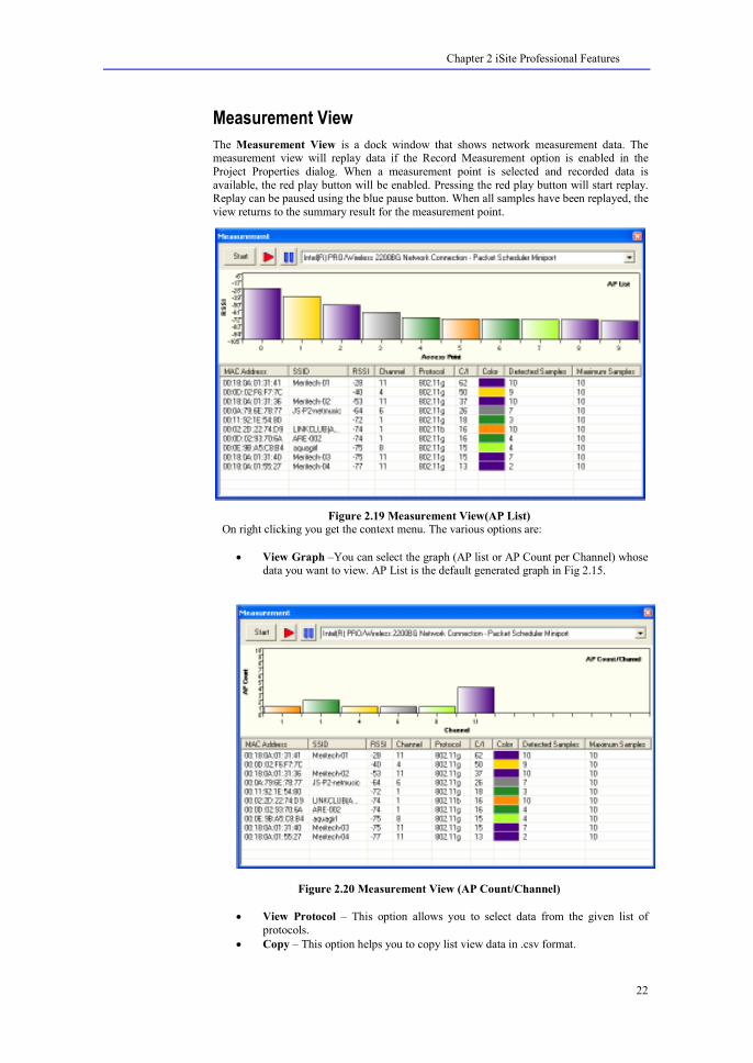
Measurement View
The Measurement View is a dock window that shows network measurement data. The measurement view will replay data if the Record Measurement option is enabled in the
Project Properties dialog. When a measurement point is selected and recorded data is
available, the red play button will be enabled. Pressing the red play button will start replay. Replay can be paused using the blue pause button. When all samples have been replayed, the
view returns to the summary result for the measurement point.
Figure 2.19 Measurement View(AP List)
On right clicking you get the context menu. The various options are:
• View Graph –You can select the graph (AP list or AP Count per Channel) whose data you want to view. AP List is the default generated graph in Fig 2.15.
Figure 2.20 Measurement View (AP Count/Channel)
• View Protocol – This option allows you to select data from the given list of
protocols.
• Copy – This option helps you to copy list view data in .csv format.
Chapter 2 iSite Professional Features
23
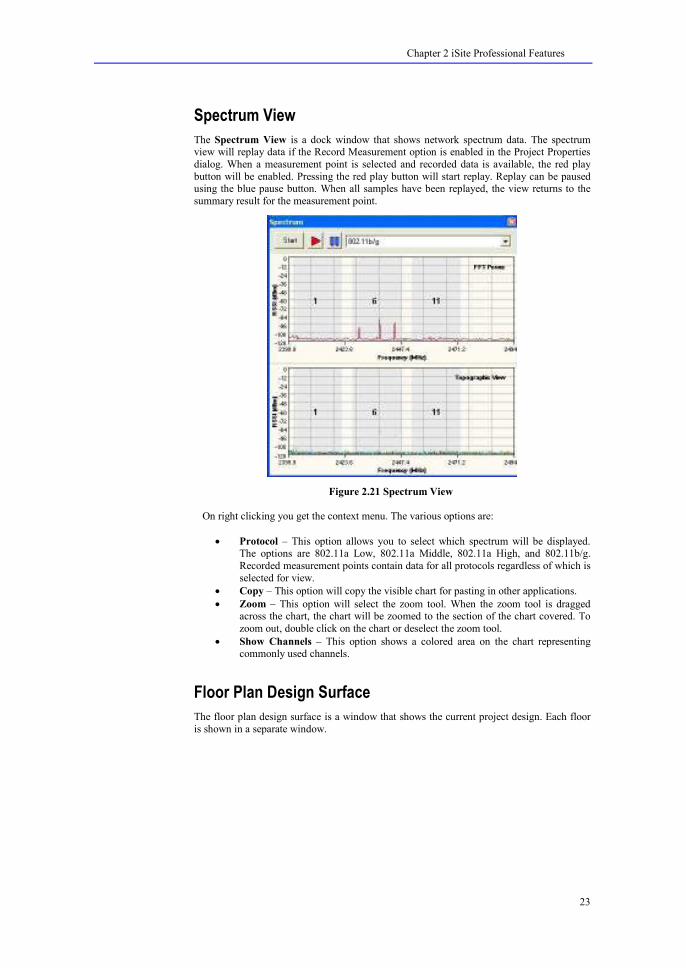
Spectrum View
The Spectrum View is a dock window that shows network spectrum data. The spectrum view will replay data if the Record Measurement option is enabled in the Project Properties
dialog. When a measurement point is selected and recorded data is available, the red play
button will be enabled. Pressing the red play button will start replay. Replay can be paused using the blue pause button. When all samples have been replayed, the view returns to the
summary result for the measurement point.
Figure 2.21 Spectrum View
On right clicking you get the context menu. The various options are:
• Protocol – This option allows you to select which spectrum will be displayed. The options are 802.11a Low, 802.11a Middle, 802.11a High, and 802.11b/g.
Recorded measurement points contain data for all protocols regardless of which is
selected for view.
• Copy – This option will copy the visible chart for pasting in other applications.
• Zoom – This option will select the zoom tool. When the zoom tool is dragged across the chart, the chart will be zoomed to the section of the chart covered. To
zoom out, double click on the chart or deselect the zoom tool.
• Show Channels – This option shows a colored area on the chart representing commonly used channels.
Floor Plan Design Surface
The floor plan design surface is a window that shows the current project design. Each floor
is shown in a separate window.

Chapter 2 iSite Professional Features
24
Figure 2.22 Floor Plan Design Surface
Customizing Workspace You can customize the workspace elements as per your convenience. The views can be docked to any side of the Window, you can hide or show toolbars, switch the application to
full screen mode, and many more.
Full Screen View
iSite Professional provides full screen view of design surface, during this modes the design
surface along with menu bar is enlarged to full screen size. This can be activated by clicking
the menu option View ���� Full Screen. To restore the application to normal mode, again click the View ���� Full Screen menu option.
Showing and Hiding Toolbars
You can hide or show toolbars to optimize the layout of iSite Professional user interface. To hide or show a toolbar, right click the toolbar area and from the popup menu check or
uncheck the toolbar which you want to show or hide respectively.
Zoomed View
iSite Professional provides the zoomed view of the design surface. To zoom the surface,
select the Zoom tool from the Tools toolbar. Then zooming in or out is possible by using the
left and right mouse buttons on design surface. You can also zoom in or zoom out the design surface by a specified factor by navigating View ���� Zoom and then from the zoom
submenus select a factor to zoom.
Other Features Various other features supported by iSite Professional are:
Clipboard Functionality
iSite Professional supports clipboard functionality to cut, copy, and paste design elements to the same or the other floor plans. To cut the selected design elements, click Edit ���� Cut or
press Ctrl+X from keyboard. To invoke copy operation, click Edit ���� Copy or press Ctrl+C.
To paste the element in the clipboard, click Edit ���� Paste or press Ctrl+V. An element added to the design surface can be deleted by selecting the element and clicking Edit ����
Delete menu option or by just pressing the Delete key on the keyboard. These operations can
be performed by selecting the appropriate menu options from the context menu of design

Chapter 2 iSite Professional Features
25
surface. The visible design surface can be copied by clicking Edit����Copy Visible Area. It
copies the visible area to the clipboard from where it can be pasted to other applications like MS Word etc. The copied visible area can also be pasted as an image element on any floor
plan.
� You need to select the appropriate design layer before selecting the elements on the design surface.
Undo-Redo Buffer
iSite Professional provides unlimited Undo/Redo functionality to the design surface
elements. So it is possible to revert the modifications done on the design surface. To undo the recent modification, click Edit ���� Undo or press Ctrl+Z. To redo the recently undone
operation, click Edit ���� Redo or press Ctrl+Y.
File Types
iSite Professional utilizes a variety of file formats as follows:
• Project File: Used to store the current project. The file uses an IST extension.
• Materials File: Used to store a list of materials. The file uses an XML extension.
• Transceivers File: Used to store a list of transceivers. The file uses an XML extension.
• Antenna Patterns File: Used to store a list of antenna patterns. The file uses TXT
extension.
• Image File: Used when adding an image to the design surface. The files types
supported are BMP, JPG, JPEG, and GIF.
• Configuration File: Used to export the configuration for access points and measurement points. The file uses an CSV extension.

Chapter 3 Using iSite Professional Survey
26
C H A P T E R 3
The process of setting up and using iSite Professional for network survey is simple and quick.
This chapter explains the steps required to survey the network.
Chapter Overview The following points are explained in this chapter.
• Starting a New Project
• Preparing to Survey
• Survey the Network
• View the Network Performance
Starting a New Project
� You must have the appropriate license to use the survey features described in this chapter.
The process for setting up a new iSite Professional project is described below.
1. Choose the File->8ew menu option.
2. Using the Project Explorer, add three new floor plans by pressing the Add
Floor button three times. The project explorer with floor plans appears as shown
in following figure.
Using iSite for Survey

Chapter 3 Using iSite Professional Survey
27
Figure 3.1 Add Floor Plans
3. Right click project or floor plan node and choose Rename in the context menu to
change the name of the project or floor plans respectively.
4. Select the Project->Project Properties menu option.
Chapter 3 Using iSite Professional Survey
28
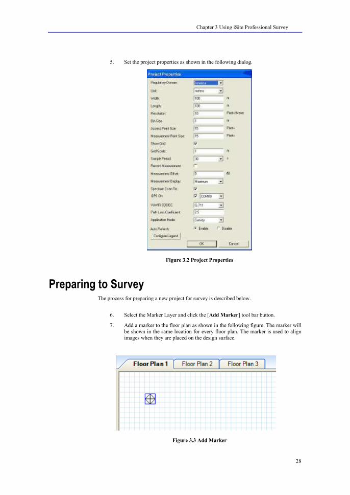
5. Set the project properties as shown in the following dialog.
Figure 3.2 Project Properties
Preparing to Survey The process for preparing a new project for survey is described below.
6. Select the Marker Layer and click the [Add Marker] tool bar button.
7. Add a marker to the floor plan as shown in the following figure. The marker will
be shown in the same location for every floor plan. The marker is used to align
images when they are placed on the design surface.
Figure 3.3 Add Marker

Chapter 3 Using iSite Professional Survey
29
8. Select the Image Layer and click the [Add Image] tool bar button. An Open File dialog will appear allowing you to select the desire floor plan image to add.
9. After selecting the file, an Image Quality dialog appears that allows you to
change the quality of the image as shown in the following figure.
Figure 3.4 Controlling Image Quality
10. Change the quality of the image if required and click OK button. Add that image
to the floor plan as shown in the following figure.
Figure 3.5 Add Image

Chapter 3 Using iSite Professional Survey
30
11. With the image selected, choose the Scale Image Tool.
12. Click and drag the scale image tool across the scale in the image as shown in the
following figure.
Figure 3.6 Scale Image
13. A dialog will appear as shown in the following image so that you can define the correct length of the scale. After pressing [Ok], the image size will change to the
correct scale.
Figure 3.7 Define Scale
14. Select the image and align it with the marker as shown in the following image.
Figure 3.8 Align Image
15. Repeat these steps as desired for the other floor plans.

Chapter 3 Using iSite Professional Survey
31
Survey the Network The process for surveying the network is described below.
� : Some WLA adaptors will return poor scan results if the PC is associated with an access point. It is recommended that the PC not be associated to any access points.
1. Select the Measurement Layer and click the [Add Measurement Point] tool bar button.
2. Select the Measurement view from the View menu and dock it at the right side of
the screen. You will notice that the Measurement View begins to update with new measurement information. Any AP which is automatically detected will be added
to the “Unassigned” group in the project explorer.
3. Locate your current position on the floor plan and click it. You will see a red circle added to the map, this color of the circle will change to green after the
sample period duration which is 1 second for the current project.
4. Add a few more measurement points. After adding at least three points, you will see the coverage plot for all AP that are enabled. The figure below shows the floor
plan after six measurement points are added.
Figure 3.9 Add Access Point
5. Continue to add measurement points until the survey area is complete. It is
recommended to record one measurement point every 3 meters.
View the Network Performance
The process for viewing network performance is described below.
1. Select the Coverage Result plot to see the coverage for all enabled AP.

Chapter 3 Using iSite Professional Survey
32
Figure 3.10 Coverage Result Plot
2. Select the Interference Result plot to see interference for all enabled AP. Enable
unassigned AP to see if they are interfering with the network.
Figure 3.11 Interference Result Plot
3. Select the Best Server Result plot to see the coverage areas for each enabled AP.

Chapter 3 Using iSite Professional Survey
33
Figure 3.12 Best Server Result Plot
4. Locate unknown AP by enabling them in the unassigned list and showing the coverage result plot. You can move Access Points from Unassigned floor to other
visible floors by right-clicking the Access Points in the Project Explorer View.
Figure 3.13 Locate Unknown AP

Chapter 3 Using iSite Professional Survey
34
5. Select the VoWiFi Calls Result plot to see the Number of calls for each enabled
AP .
Figure 3.14 VoWiFi Calls Result Plot
Chapter 4 Using iSite Professional Design
35
C H A P T E R 4
The process of setting up and using iSite Professional for network design is simple and quick.
This chapter explains the steps required to create and optimize a basic design.
Chapter Overview The following points are explained in this chapter.
• Starting a New Project
• Preparing to Design
• Creating the Design
• Optimizing the Design
Starting a New Project
� You must have the appropriate license to use the design features described in this chapter.
The process for setting up a new iSite Professional project is described below.
1. Choose the File->8ew menu option.
2. Using the Project Explorer, add three new floor plans by pressing the Add Floor button three times. The new floor plans are shown in the following image.
Using iSite for Design

Chapter 4 Using iSite Professional Design
36
Figure 4.1 Add Floor Plans
3. Right click and choose Rename in the context menu to change the name of the project and floor plans.
4. Select the Project->Project Properties menu option.
5. Set the project properties as shown in the following dialog.
Chapter 4 Using iSite Professional Design
37
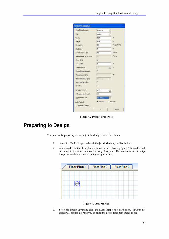
Figure 4.2 Project Properties
Preparing to Design The process for preparing a new project for design is described below.
1. Select the Marker Layer and click the [Add Marker] tool bar button.
2. Add a marker to the floor plan as shown in the following figure. The marker will
be shown in the same location for every floor plan. The marker is used to align
images when they are placed on the design surface.
Figure 4.3 Add Marker
3. Select the Image Layer and click the [Add Image] tool bar button. An Open file dialog will appear allowing you to select the desire floor plan image to add.

Chapter 4 Using iSite Professional Design
38
4. After selecting the file, an Image Quality dialog appears that allows you to change
the quality of the image as a lower quality image have better UI performance.
5. Change the quality of the image if required and add that image to the floor plan as
shown in the following figure.
Figure 4.4 Add Image
6. With the image selected, choose the Scale Image Tool.
7. Click and drag the scale image tool across the scale in the image as shown in the following figure.
Figure 4.5 Scale Image
8. A dialog will appear as shown in the following image so that you can define the
correct length of the scale. After pressing [Ok], the image size will change to the correct scale.

Chapter 4 Using iSite Professional Design
39
Figure 4.6 Define Scale
9. Select the image and align it with the marker as shown in the following image.
Figure 4.7 Align Image
10. Select the Barrier Layer and click the [Add Barrier] tool bar button.
11. Add barriers by clicking and dragging the tool over the design surface. The
following image shows barriers that were drawn to cover the image.
Figure 4.8 Add Barrier
12. Repeat these steps as desired for the other floor plans.

Chapter 4 Using iSite Professional Design
40
Creating the Designing The process for creating a new iSite Professional design is described below.
1. Select the Access Point Layer and click the [Add Access Point] tool bar button.
2. Add an access point to the design surface. The coverage for the access point will
be automatically calculated and displayed as shown in the following image.
Figure 4.9 Add Access Point
3. Add additional access points as desired.
Optimizing the Designing The process for optimizing a design is described below.
1. Select the Coverage Result Layer and view the results. Adjust the access point positions as required to cover all desired area. The following image shows the
coverage result layer with three access points.

Chapter 4 Using iSite Professional Design
41
Figure 4.10 Coverage Result Plot
2. Select the Interference Result Layer and view the results. Adjust the access point channel configuration as required to reduce interference. The following image
shows the interference result layer with three access points. Interference was minimized by using channels 1, 6, and 11 for each access point.
Figure 4.11 Interference Result Plot
3. Select the Best Server Result Layer and view the results. Adjust the access point
location as required to control the load on each access point. The more users
covered by an access point, the higher the load.

Chapter 4 Using iSite Professional Design
42
Figure 4.12 Best Server Result Plot
25. Select the VoWiFi Result Layer and view the results. Adjust the access point positions as required to cover all desired area. The following image shows the VoWiFi
result layer with three access points.
Figure 4.13 VoWiFi Result Plot
Chapter 5 Using iSite Professional Mixed Mode
43
C H A P T E R 5
This chapter explains the steps required to run the application in mixed mode.
Chapter Overview The following points are explained in this chapter.
• Mixed Mode Overview.
• Starting a New Project.
• Getting the Mixed Mode Results.
Mixed Mode Overview Every Access Point has a plot mode property associated to it. This property determines that if the access point is to be considered under prediction or survey mode. In the Design mode, all
access points have their plot mode set to prediction while in survey mode, this property is set
to Survey. In mixed mode, every access point can have plot mode either set to prediction or to survey. For access points in prediction mode, the signal strength is predicted on all floors.
The access points detected in real time survey have their plot mode property set to survey.
For these access points the signal strength is calculated on floor plan by interpolating between the values measured at the measurement point locations.
The purpose of having a mixed mode project is to allow the user to have both survey and
design capabilities simultaneously. Typically a user would conduct a survey by placing measurement points at various points on the floor plan and then he would add a few access
points with plot mode set to prediction to have an idea how the measured coverage plot
would change if there were more access points added on the floor at specific locations.
Starting a New Project
� You must have the appropriate license to use the design and survey feature.
The process for setting up a new iSite Professional project is described below.
1. Choose the File->8ew menu option.
Using iSite in Mixed Mode

Chapter 5 Using iSite Professional Mixed Mode
44
2. Using the Project Explorer, add three new floor plans by pressing the Add Floor
button three times. The new floor plans are shown in the following image.
Figure 5.1 Project Explorer
3. Right click and choose Rename in the context menu to change the name of the
project and floor plans.
4. Select the Project->Project Properties menu option.
5. Set the project properties as shown in the following dialog:

Chapter 5 Using iSite Professional Mixed Mode
45
Figure 5.2 Project Properties
Getting the Mixed Mode Results
The process for preparing a new project for mixed results is described below.
6. Select the Marker Layer and click the [Add Marker] tool bar button.
7. Add a marker to the floor plan as shown in the following figure. The marker will
be shown in the same location for every floor plan. The marker is used to align
images when they are placed on the design surface.
Figure 5.3 Add Marker

Chapter 5 Using iSite Professional Mixed Mode
46
8. Select the Image Layer and click the [Add Image] tool bar button. An Open file
dialog will appear allowing you to select the desire floor plan image to add.
9. After selecting the file, an Image Quality dialog appears that allows you to change
the quality of the image as a lower quality image have better UI performance.
10. Change the quality of the image if required and add that image to the floor plan as shown in the following figure.
Figure 5.4 Add Image
11. With the image selected, choose the Scale Image Tool.
12. Click and drag the scale image tool across the scale in the image as shown in the
following figure.
Figure 5.5 Scale Image
13. A dialog will appear as shown in the following image so that you can define the
correct length of the scale. After pressing [Ok], the image size will change to the
correct scale.
Chapter 5 Using iSite Professional Mixed Mode
47
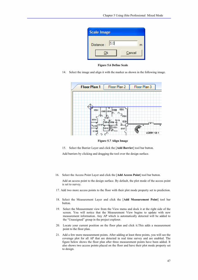
Figure 5.6 Define Scale
14. Select the image and align it with the marker as shown in the following image.
Figure 5.7 Align Image
15. Select the Barrier Layer and click the [Add Barrier] tool bar button.
Add barriers by clicking and dragging the tool over the design surface.
16. Select the Access Point Layer and click the [Add Access Point] tool bar button.
Add an access point to the design surface. By default, the plot mode of the access point is set to survey.
17. Add two more access points to the floor with their plot mode property set to prediction.
18. Select the Measurement Layer and click the [Add Measurement Point] tool bar
button.
19. Select the Measurement view from the View menu and dock it at the right side of the screen. You will notice that the Measurement View begins to update with new
measurement information. Any AP which is automatically detected will be added to
the “Unassigned” group in the project explorer.
20. Locate your current position on the floor plan and click it.This adds a measurement
point to the floor plan.
21. Add a few more measurement points. After adding at least three points, you will see the coverage plot for all AP that are detected in real time survey and are enabled. The
figure below shows the floor plan after three measurement points have been added. It
also shows two access points placed on the floor and have their plot mode property set to design.

Chapter 5 Using iSite Professional Mixed Mode
48
Figure 5.8 Coverage Plot
22. Similarly, other result layers can be selected to view the results i.e. Interference, Best
Server, Throughput, VoWiFi, Coverage Overlap and Security Leak.

Chapter 6 Configuring Components
49
C H A P T E R 6
This chapter explains the procedure to organize and manage an iSite Professional project.
Chapter Overview The following points are explained in this chapter.
• Configuring Layers
• Configuring Results
• Configuring Design Elements
• Configuring Materials
• Configuring Transceivers
• Configuring Antenna Patterns
• Configuring Project Properties
Configuring Layers As in iSite Professional every design and result element has an associated layer on which they operate. You can change the appearance of the elements by changing the properties of
their corresponding layer. For example, you can make the floor area on the design surface
invisible by changing its layer’s properties. Properties associated with layers are:
Property 8ame Description
Name It is a read only property that
displays name of the layer.
Opacity
Allows you to change the transparency of corresponding
elements from 0 (completely
transparent) to 100 (completely opaque).
Printable Boolean value, set to true to make
the corresponding elements printable.
Visible Boolean value, set to false to
make corresponding elements
invisible.
Table 6.1 Properties of a Layer
Configuring Components

Chapter 6 Configuring Components
50
• To change the property of a layer, select that desired layer from Elements or Results Layer toolbar.
Properties View will reflect the properties associated with that layer and allow you to change the properties. The properties of Floor Area Layer will appear as shown in following figure.
Figure 6.1 Configuring Layers
• The Layer View is used to select the active layer and change layer properties.
Figure 6.2 Configuring design elements Layers
Configuring Results Results for Coverage and Interference generated by iSite Professional in prediction or survey
mode can be configured. To configure these results, click Configure Legend button of Project Properties dialog or right click the design surface and from the context menu, select
Legend Configuration menu option. The legend Configuration dialog appears as shown in
following figure.

Chapter 6 Configuring Components
51
Figure 6.3 Legend Configuration Dialog
From this dialog, select plot type for which you want to configure the legend and then select type of legend, as it can be either Graded or Discrete. Select the appropriate legend type and
set the range, click OK button to save the changes.
Configuring Design Elements Every design element has some user configurable properties, for example for an Access Point
you can change, the type of the Access Point, channel on which it is operating, its MAC
address, and many more. To change the property corresponding to an element drawn on the design surface, select that element using pointer tool and the Properties View will reflect the
properties corresponding to that element. You can also view the properties by right clicking
that element and from the pop up menu select Properties menu option.
Following figure displays the properties corresponding to an Access Point.

Chapter 6 Configuring Components
52
Figure 6.4 Configuring Element’s Properties
Configuring Materials As every iSite Professional project has a list of materials that are used to draw barrier and
floor area on the design surface. Materials can be added or removed. The whole list of
materials can be imported or exported as well as you can configure a material as per your requirements. Material View appears as shown in following figure:

Chapter 6 Configuring Components
53
Figure 6.5 Materials View
Material View has a toolbar that allows you to perform operation on the list of materials. The
items provided by toolbar are described in the following table.
Toolbar Item Description
Add Click thiSite Professional m to
add a new material to the project.
Remove Click thiSite Professional m to
delete the selected material from the project.
Import Click thiSite Professional m to
import the materials list to an xml
file.
Export Click thiSite Professional m to
export the materials list from an
xml file.
Set Default Click thiSite Professional m to set the selected material as a default
material.
Table 6.2 Material View Toolbar
To change the property of a material, select the required material from the Materials View
and the Properties View will displays the configurable properties of the selected material. The following figure displays the properties of Concrete.
Chapter 6 Configuring Components
54
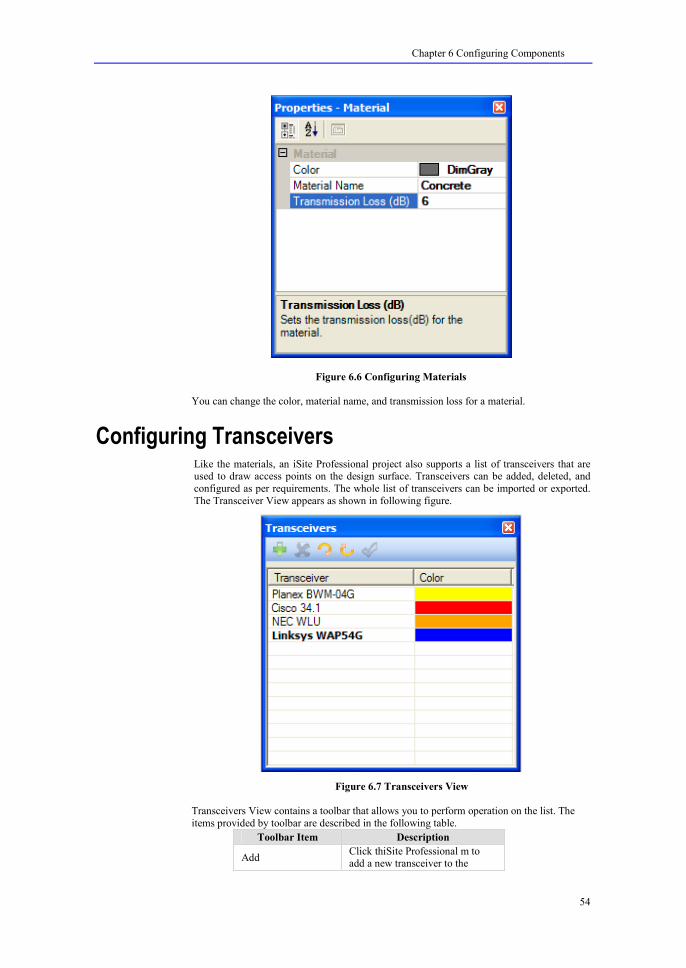
Figure 6.6 Configuring Materials
You can change the color, material name, and transmission loss for a material.
Configuring Transceivers Like the materials, an iSite Professional project also supports a list of transceivers that are used to draw access points on the design surface. Transceivers can be added, deleted, and
configured as per requirements. The whole list of transceivers can be imported or exported.
The Transceiver View appears as shown in following figure.
Figure 6.7 Transceivers View
Transceivers View contains a toolbar that allows you to perform operation on the list. The
items provided by toolbar are described in the following table.
Toolbar Item Description
Add Click thiSite Professional m to add a new transceiver to the

Chapter 6 Configuring Components
55
project.
Remove Click thiSite Professional m to delete the selected transceiver
from the project.
Import Click thiSite Professional m to import the transceivers list to an
xml file.
Export Click thiSite Professional m to
export the transceivers list from an xml file.
Set Default Click thiSite Professional m to set
the selected transceiver as a default transceiver.
Table 6.3 Transceivers View Toolbar
To change the property of a transceiver, select the required transceiver from the
Transceivers View and the Properties View will displays the configurable properties of the
selected transceiver. The following figure displays the properties of a Cisco transceiver.
Figure 6.8 Configuring Transceivers
You can change the Antenna gain of the transceiver, its Antenna Pattern, protocol, RF Power,
and many other important properties.

Chapter 6 Configuring Components
56
Configuring Antenna Patterns As every transceiver has an antenna pattern associated to it, iSite Professional allows you to
have a list of different antenna patterns Antenna patterns can be added, edited and deleted
from the list. Antenna Pattern list can be imported and exported in text format. Antenna Pattern View appears as below:
Figure 6.9 Configuring Antenna Patterns
Omni Directional antenna pattern cannot be removed from the list. You cannot even change its name.
Antenna Pattern View has a toolbar that lets you perform different operations to the list.
Following table describes the various options provided on toolbar:
Toolbar Item Description
Add Click this item to add a new
antenna pattern to the project.
Remove Click this item to delete the selected antenna pattern from the
project.
Import Click this item to import the antenna patterns list to a txt file.
Export Click this item to export the
antenna patterns list from a txt
file.
Set Default Click this item to set the selected antenna pattern as the default one.
Edit Click this item to edit the selected
antenna pattern.
Table 6.4 Antenna Pattern View Toolbar

Chapter 6 Configuring Components
57
Clicking the Add button adds a new antenna pattern to the list. This pattern has the default
settings of omni directional antenna pattern. These settings can be changed by editing the pattern. A pattern can be edited by selecting the pattern and clicking the Edit button or
selecting Edit option from the context menu. Properties of an antenna pattern can be set
through the following dialog:
Figure 6.10 Editing antenna pattern
The different antenna pattern properties are explained below:
Item Description
Name Allows you to change the name of antenna pattern.
Azimuth Data Points Allows you to enter the gain value
corresponding to different degrees
for Azimuth view.
Elevation Data
Points
Allows you to enter the gain value
corresponding to different degrees
for Elevation view.
Table 6.5 Antenna Pattern Properties
As you enter the degree and its corresponding gain value in the grids, values get displayed on the respective graphs. Clicking OK saves the changes made.
The patterns formed for the Azimuth and Elevation planes can also be viewed in the
properties grid. Selecting an antenna pattern displays its graphs in the properties grid as:

Chapter 6 Configuring Components
58
Figure 6.11 Antenna Pattern Properties
Configuring Project Properties The Project Properties dialog is used to configure items that effect the overall operation of
iSite Professional for the current project. The properties can be configured as:

Chapter 6 Configuring Components
59
Figure 6.12 Project Properties
The elements of project properties are explained below:
Item Description
Regulatory Domain Allows you to change the
regulatory domain from America, EMEA, Japan, and Rest of world.
Unit Allows you to select measurement
unit as meter or feet.
Width Allows you to set the width of the
design surface.
Length Allows you to set the length of the
design surface.
Resolution Allows you to change the
resolution of the design surface.
Bin Size Allows you to change the size of bin. A bin is the smallest size for
which engine calculate results.
Access Point Size Allows you to change the size of
access point.
Measurement Point
Size
Allows you to change the size of
measurement point.
Show Grid Check this checkbox to show gridlines on design surface.
Uncheck it to hide the gridlines
Grid Scale Allows you to change the distance
between the grid lines on the design surface.
Sample Period This feature is available in survey
mode only and allows you to set

Chapter 6 Configuring Components
60
the duration of sample period for
measurement points. Sample period specifies the duration for
which measurement are taken for a
measurement point
Record Measurement
If enabled, all measurement data
will be recorded within each
sample period. If disabled, only the summary data will be recorded
for each sample period.
Measurement Offset Allows you to make changes to
measured RSSI values.
Measurement Display
Survey data result plots will use this measurement value type
Spectrum Scan On
If enabled, spectrum data will be recorded. A spectrum scanner
device must be installed for this
option to function properly.
GPS On
Allows you to select COM port for the GPS device attached. Once
COM port is selected, GPS
position will start showing on floor plan. GPS device must be installed
and connected to the PC for this
option to function properly.
VoWiFi Codec Allows you to select a VoWiFi Codec.
Path Loss Coefficient Allows you to set the value of path
loss coefficient.
Application Mode Allows you to change the
application mode as survey ,
prediction or mixed.
Auto Refresh If enabled, results will be updated when the project is modified.
Configure Legend Click this button if you want to
configure the color of result
legends.
Table 6.6 Project Properties

Chapter 7 Reports
61
C H A P T E R 7
Chapter Overview The following points are explained in this chapter.
• Opening Report Dialog
• Generate Report in Survey Mode
• Generate Report in Design Mode
Opening Report Dialog User should have one or more floor plans with Access Points and Measurement Points to generate a Report.
To open Reports Dialog, left click the [Reports View] button on View Toolbar. You can also open Reports Dialog by navigating Results ���� Reports.
Generate Report in Survey Mode iSite Professional Provides Summary Report and Measurement Point Report to in Survey
Mode. To Open Report in Survey mode, you should have floor plans configured as explained in Chapter 3 above.
You can select Summary Report or Measurement Report in Survey Mode. Summary Report
shows images of all the Floor Plans in project and details of all the access points on all the
floors. Measurement Report shows the details of all the measurement points drawn on all the floors.
The process for opening Reports Dialog is described below.
1. Click Reports View in View tool bar.
2. Select [Summary Report] to generate Summary Report containing image of all floor plans and details of all access points on all the floors.
3. Click [Generate Report].
Using Reports

Chapter 7 Reports
62
Figure 7.1 Summary Report showing Floor Image
Summary Report displays following result plots of all floors in a page wise manner. i.e. One page of the
report displays one of following result plot for each floor.
• Coverage.
• Interference.
• Throughput.
• VoWiFi calls.
• Best Server.
• Coverage Overlap.
• Security leak.
Name of the floor plan is displayed at the top of the image.
Figure 7.2 Summary Report Access Points
Last page of the report shows the details of all the access points present on all the floors. It lists the
following properties of the access point:
• 8ame of the Access point.
• Type of the Access point.

Chapter 7 Reports
63
• Channel associated to the Access point.
• X position of the Access point.
• Y position of the Access point.
• MAC Address of the Access point.
• SSID value of the Access point.
• Antenna Gain associated to the Access point.
• Make associated to the Access point.
• Model associated to the Access point.
• Protocol associated to the Access point.
• RF Power associated to the Access point.
• Floor on which Access point is present.
• Enabled state of the Access point.
It appears as shown in the following figure:
Figure 7.3 Measurement Point Report
This report shows the details of all the measurement points present on all the floors. The details include the following measurement point properties:
• 8ame of the measurement point.
• Floor on which the measurement point is present.
• X position of the measurement point.
Generate Report in Design Mode iSite Professional provides Summary Report in the Design Mode
To open report in Survey mode, you should have floor plans configured as explained in
Chapter 4 above.
The process for opening Reports Dialog is described below.
1. Click Reports View in View tool bar.

Chapter 7 Reports
64
2. Select [Summary Report] to generate Summary Report containing image of all
floor plans and details of all access points on all the floors.
3. Click [Generate Report].
Figure 7.4 Summary Report showing Image of Floor Plan
The report displays following result plots generated for each floor from access points present in
the project.
• Coverage.
• Interference.
• Throughput
• VoWiFi calls.
• Best Server.
• Coverage Overlap.
• Security leak.
The results are displayed in a page wise manner. i.e. One page of the report displays one of the
result plot for each floor.

Chapter 7 Reports
65
Figure 7.5 Summary Report showing Access Points on Floor Plan

Appendix A Setup iSite
66
A P P E N D I X A
This appendix describes the procedure for installing and uninstalling iSite Professional .
Appendix Overview
The following points are explained in this appendix.
• System Requirements
• Installing iSite Professional
• Updating iSite Professional
• Uninstalling iSite Professional
System Requirements The following table lists the minimum system requirements essential to use iSite Professional
on your computer.
Component Specification
Processor Intel Pentium III Processor
Processor Speed 250 MHz
Memory 256 MB
Hard Drive 250 MB
Display 1024 x 768
Operating System MS Windows XP/Vista
IO Ports 1 USB Port
Table A.1 System Requirements
Installing iSite Professional
Setup iSite Professional

Appendix A Setup iSite
67
The process of installing iSite Professional is described below.
� The Microsoft . ET Framework version 2.0 must be installed on your computer
to run iSite Professional . The framework is pre-installed with most Windows XP operating systems. If your system does not have the framework, please visit the
Microsoft update web site to install the framework.
4. Insert the iSite Professional CD ROM into your computer.
5. Run the setup.exe application to install iSite Professional .
6. The following screen is displayed.
Figure A.2 iSite Professional Setup
7. Click [8ext >] to continue with the installation or [Cancel] to discontinue.
8. Upon clicking [8ext >], the following screen is displayed.

Appendix A Setup iSite
68
Figure A.3 License Agreement
9. This screen comprises the license agreement for the Meritech Co., Ltd. software.
10. If you agree to the terms of the agreement, select [I Agree] and press [8ext].
Otherwise, press [Cancel].
11. Upon clicking [8ext], the following screen is displayed.
Figure A.4 Installation Folder

Appendix A Setup iSite
69
12. By default, the wizard stores the iSite Professional application in the path
displayed in the Destination Folder area. You can select a different file by clicking [Browse].
13. Click [8ext]. The following screen is displayed.
Figure A.5 Confirm Installation
14. Click [8ext]. The following screen is displayed.
Appendix A Setup iSite
70
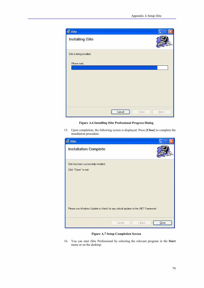
Figure A.6 Installing iSite Professional Progress Dialog
15. Upon completion, the following screen is displayed. Press [Close] to complete the
installation procedure.
Figure A.7 Setup Completion Screen
16. You can start iSite Professional by selecting the relevant program in the Start
menu or on the desktop.

Appendix A Setup iSite
71
Updating iSite Professional Incremental updates will be released with new and enhanced functionality. To install these
updates, first uninstall iSite Professional from you computer. Next, install the iSite
Professional update release. All existing data files and the user license dongle can be used with the update release.
Uninstalling iSite Professional
You can uninstall iSite Professional by selecting [Remove] for the iSite Professional item in
the Add or Remove Programs dialog. This dialog can be found in the Control Panel.
1. When [Remove] is selected, the following screen is displayed. Press [Yes] to continue.
Figure B.9 Uninstalling iSite Professional
2. During removal of iSite Professional , the following progress dialog is shown.
Figure B.10 Uninstall Message Box
3. After iSite Professional is removed, the dialog will close automatically.

Index
72
I N D E X
Access Point Element, 8
Barrier Element, 8
Best Server Result Plot, 33, 42
Configuration File, 25
Coverage Result Plot, 32, 41
Design Element Layer, 9
Edit Menu, 10
File Menu, 9
File Types, 25
Floor Area Element, 8
Floor Plan Design Surface, 23
Full screen view, 24
Help Menu, 14
Image Element, 8
Image File, 25
Information View, 21
Installing iSite Professional, 66
Interference Result Plot, 32, 41
iSite Professional, 7
Layers View, 18
Legend Configuartion, 51
List of Abbreviations, 6
Marker Element, 8
Materials File, 25
Materials View, 19
Measurement Point Element, 8
Measurement Point Report, 61
Measurement View, 22, 23
Menu Bar, 9
microcell network design, 7
Project Explorer, 18
Project File, 25
Project Menu, 12
Properties View, 20
Result Layer, 9
Result Menu, 13
Scale Image Tool, 30, 38, 46
Security Area Element, 8
Status Bar, 17
Summary Report, 61
System Requirements, 66
Tool Bar, 15
Tools Menu, 12
Transceivers File, 25
Transceivers View, 19, 20
Uninstalling iSite Professional, 71
Updating iSite Professional, 71
View Menu, 11
VoWLAN, 6
Windows Menu, 14
WLAN, 7
Workspace Elements, 9