islanding detection in microgrids using harmonic signatures
TRANSCRIPT
0885-8977 (c) 2013 IEEE. Personal use is permitted, but republication/redistribution requires IEEE permission. Seehttp://www.ieee.org/publications_standards/publications/rights/index.html for more information.
This article has been accepted for publication in a future issue of this journal, but has not been fully edited. Content may change prior to final publication. Citation information: DOI10.1109/TPWRD.2014.2383412, IEEE Transactions on Power Delivery
1
Islanding Detection in MicrogridsUsing Harmonic Signatures
Julia Merino, Student Member, IEEE, Patricio Mendoza-Araya, Member, IEEE,Giri Venkataramanan, Senior Member, IEEE, and Mustafa Baysal, Member, IEEE,
Abstract—In the recent years, there has been a growing interestin incorporating microgrids in electrical power networks. This isdue to various advantages they present, particularly the possi-bility of working in either autonomous mode or grid-connected,which make them highly versatile structures for incorporatingintermittent generation and energy storage. However, they posesafety issues in being able to support a local island in case ofutility disconnection. Thus, in the event of an unintentional islandsituation, they should be able to detect the loss-of-mains anddisconnect for self-protection and safety reasons. Most of theanti-islanding schemes are implemented within control of singlegeneration devices such as dc-ac inverters used with solar electricsystems are incompatible with the concept of microgrids due tothe variety and multiplicity of sources within the microgrid. Inthis paper a passive islanding detection method based on thechange of the 5th harmonic voltage magnitude at the point ofcommon coupling between grid connected and islanded modes ofoperation is presented. Hardware test results from the applicationof this approach to a laboratory scale microgrid are shown. Theexperimental results demonstrate the validity of the proposedmethod, in meeting the requirements of IEEE 1547 standards.
Index Terms—Harmonic signature, Islanding detectionmethod, Microgrid
I. INTRODUCTION
Anti-islanding is an important operational requirement thathas been developed in integrating distributed generation
to a large centralized electrical network. In the event of an un-scheduled outage in the electrical grid, a distributed generationdevice may continue supplying the local loads by forming anisland. In this condition, the local loads remain energized, butthe grid’s centralized control system may not have capability toregulate the island, precluding any utility operations personnelfrom performing corrective functions to restore power in a safemanner. Thus, interconnection codes have been developed to
Manuscript received January 14, 2014. This work has been partiallyfunded by the Spanish Ministry of Economy and Competitiveness un-der the grant BES-2010-034386; the United Technologies Research Centerthrough Professional Services Agreements numbered PSA-1159925 underUnited States Government Contract Number W912HQ-09-C-0055, and PSA-1169296 under United States Government Contract Number DE-EE0003954;TUBITAK-BIDEB 2219 programme; and by CONICYT/FONDAP/15110019.
J. Merino is with the Department of Electrical Engineering, TechnicalUniversity of Madrid, 28006 Spain, e-mail: [email protected].
J. Merino is also with the Smart Grids and Energy Storage Area of TecnaliaR&I, Derio, E-48160 Spain, email: [email protected]
P. Mendoza-Araya is with the Electrical Engineering Department, EnergyCenter, University of Chile, Santiago, Chile, e-mail: [email protected]
G. Venkataramanan is with the Department of Electrical and ComputerEngineering, University of Wisconsin, Madison, WI 53706 USA (e-mail:[email protected])
M. Baysal is with Yildiz Technical University, Department of ElectricalEngineering, Istanbul, Turkey, e-mail: [email protected]
ensure that any distributed generation device connected to thegrid will disconnect in the event of an outage in the utilitywithin a specified interval of time [1]. On the other hand,a microgrid is a local electrical network that (1) comprisespower generation sources, loads, and a means of deliveringpower from the generation units to the loads, (2) may beconnected to a larger utility power system, and (3) operates tobalance the power supply and demand within the microgrid.The microgrid paradigm is rapidly emerging as a flexibleapproach to aggregate diverse distributed and intermittentrenewable energy sources and storage devices with the electricgrid in a safe and reliable manner. As such a microgrid mayoperate in both islanded mode or grid-connected mode. Sincea microgrid is intentionally designed to support local loadsin island mode, traditional anti-islanding approaches pose aconundrum. This paper proposes an operating methodologythat defines responsibility centers for anti-islanding protectionin microgrids, and presents a viable and practical procedure torealizing anti-islanding protection to ensure a safe operatingprotocol to overcome this conundrum.
In Section II of this paper, an extensive summary of variousislanding detection schemes, along with extensions to micro-grids is presented. Section III presents the proposed islandingdetection based on harmonics signatures, along with a basisfor the proposed approach. Validation of the approach basedon experimental tests is discussed in Section IV. Finally, asummary of the results of the work is presented in Section V.
II. ISLANDING DETECTION METHODS
Islanding detection methods (IDMs) are numerous and itis easy to find in the literature detailed classifications andreviews. At the outset IDMs can be classified as remote orlocal. Remote detection methods are under the authority of thesystem operator and they are located at the utility level. Thesetechniques are generally quite reliable but their implementationis rather expensive and typically reserved for large scale unitswith extensive SCADA systems well integrated with utilitycontrol systems, and thus are not compatible with the visionof microgrids. On the other hand, local detection methodsare directly implemented at each generator. Traditionally theyhave been located inside the inverters used with solar electricsystems. Local detection methods can be further split in twomain categories: passive and active.
A. Passive methodsPassive methods are those where measurement and moni-
toring of a significant magnitude is needed in order to per-

0885-8977 (c) 2013 IEEE. Personal use is permitted, but republication/redistribution requires IEEE permission. Seehttp://www.ieee.org/publications_standards/publications/rights/index.html for more information.
This article has been accepted for publication in a future issue of this journal, but has not been fully edited. Content may change prior to final publication. Citation information: DOI10.1109/TPWRD.2014.2383412, IEEE Transactions on Power Delivery
2
form the detection, adjusting the protection system thresholds,but without any control action over the rest of the system.Some simple methods are rooted in the analysis of a singlemagnitude. This is the case of traditional methods such as:over/under frequency [2] unusual change of active power,frequency [3], voltage [2], reactive power [4], jumps in thevoltage phase [5] or phase angle difference [6]. In case ofa generation-load imbalance produced by an islanding event,fluctuations in these measurements can be easily detected.New research of passive IDMs procedures have also beendefined applying highly topical tools like wavelet transform[7], neural networks or decision trees [8]. Different methodswhich relate more than one quantity can also be found, suchas [9] where simultaneous changes in frequency and activepower are analyzed or variations produced at the PCC in boththe voltage imbalance and the current THD [10] among manyothers. The main disadvantage passive methods shall presentis an significant non-detection zone (NDZ), certain regions inthe real/reactive power plane in which variations in voltageand frequency levels can be so small to be undetectable.
B. Active methods
Active methods introduce an additional external variable, acontrolled change or a positive feedback to detect the islandingcondition. They are much more effective than the passive ones,and generally do not feature any NDZs. However, they arenot as fast as some passive methods because of the system’sinherent reaction time, and the implementation cost of thiskind of methods is unquestionably higher. It is quite commonto find examples of methods based on injection of a signalwith a specific frequency [11]: by measuring the impedanceat that frequency, the islanding condition can be detected [12].Some other examples introduce a positive feedback to causeperceptible changes in phase [13] or in voltage [14]. Othersolutions are founded on the use of Phase-Locked loop circuits(PLLs), by introducing a disturbance in the inverter referenceor in the inverter output. In case of islanding, phase in voltageor in current wave moves out a threshold value causing theinverter to trip [15], [16]. More detailed summaries of theseapproaches may be found in [17], [18], [19], particularly thosethat combine both active and passive techniques.
C. Extension of IDMs to microgrids
The IDMs defined above have generally been motivatedby the early efforts to integrate distributed generation unitsinto electrical grids through an inverter, particularly for solarelectric systems. Therefore, these methods are usually thoughtto be directly implemented within the inverter based source.However, it is necessary to carefully extrapolate the islandingdetection concepts in extending the concepts to next steps intechnology evolution. The first natural step in the technologyevolution is the extension of single inverter-based conceptsto the multiple-inverter case. This aspect is well documentedin technical literature [20], [21], [22]. In such multi-inverterscenarios, each inverter has an islanding detection respon-sibility within itself. These extensions do not necessarilyintroduce new IDM concepts, but takes the complexity of
interaction among the different inverters at the same pointof common coupling (PCC). The next more nuanced stepin technology evolution is the development of integration ofheterogenous sources such as solar electric systems, windgeneration systems, energy storage systems, micro turbines,combined heat and power systems (CHP) based on fossil fuels,fuel cell systems, etc. with the electric grid using the paradigmof microgrids.
There are some characteristics that establish differenceswhen extending IDMs between the single-inverter and themulti-inverter case to microgrid case. First of all, a microgridcan exchange power bidirectionally with the utility grid. Dueto this fact, the detection of islanding events represents achallenge because there are no specific tests requirementsdefined in the IEEE 1547 standards to deal with such con-ditions. Secondly, in the event of unintentional island, themicrogrid has to be disconnected at the defined point ofinterconnection to the utility grid as a whole, but not at eachgeneration and/or storage device. Otherwise, it would defeatthe microgrid concept. While some of the recent technicalliterature referring to IDM in microgrids, [23], [24], [25],[26], [27], they are all generally based on simulations of well-modeled systems within reasonably regulated model scenarios.While [24] presents an experimental model, it is demonstratedonly in a single-inverter source connected to the utility grid,thereby limiting the system level extension. Furthermore, theseIDMs place a focus on the islanding detection, but leave outthe issue of maintaining the intentional island intact after thedisconnection event.
It is therefore the intent of this paper to present a novelsolution of IDMs as applied to microgrids. It is centered onthe detection of loss of mains at the utility interconnectionpoint, where 1547 interconnection regulations are applied, andnot at each distributed generation or storage device withinthe microgrid, which may or may not consist of inverterbased generation. None of the generation devices within themicrogrid are required to have any traditional anti-islandingtechnique within their controls. Section III further outlinesthis approach, that has been verified in extensive tests in alaboratory scale microgrid with multiple heterogenous sourcesand the RLC load defined by the IEEE Std. 1547 for testingislanding detection schemes. Moreover, the IDM approach andthe formation of intentional island within the microgrid andthe removal of the unintentional island upstream are all im-plemented using commercial utility grade relaying equipment.
III. ISLANDING DETECTION METHOD BASED ONHARMONICS SIGNATURES
In the proposed methodology, the responsibility of detectionof the islanding phenomena and the subsequent disconnectionof the microgrid at the point of connection relies, not in theinverters or any other generators present within the micro-grid, but in the controls that are incorporated in the switch-ing element at the point of interconnection. The switchingelement would nominally be operated to ensure appropriaterelaying functions such as over-voltage/under-voltage, over-frequency/under-frequency, reverse power, imbalance, syn-chronism check, etc. at the point of connection. It is therefore,
0885-8977 (c) 2013 IEEE. Personal use is permitted, but republication/redistribution requires IEEE permission. Seehttp://www.ieee.org/publications_standards/publications/rights/index.html for more information.
This article has been accepted for publication in a future issue of this journal, but has not been fully edited. Content may change prior to final publication. Citation information: DOI10.1109/TPWRD.2014.2383412, IEEE Transactions on Power Delivery
3
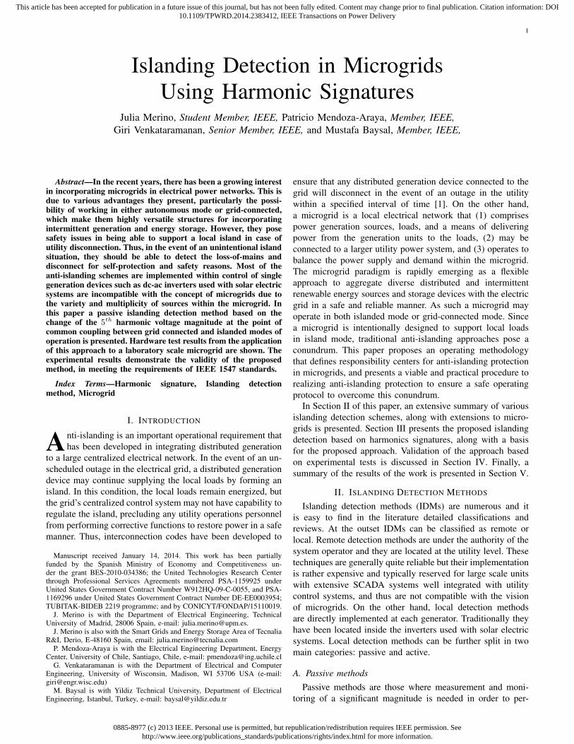
natural that the anti-islanding function also become part of thecontrol responsibilities of the relaying device. This is, in fact, avery practical solution to islanding detection in microgrids thatis compatible with existing utility relay equipment practices,while removing the burden of islanding detection away fromthe inverters and generator equipment and integrating thisfunctionality into the PCC equipment. Such an approach wouldalso be readily compatible to emerging technologies such assmart grids and allow the penetration of distributed resourceswith fewer barriers at various load locations. Fig. 1 presentsthe proposed microgrid anti-islanding responsibility in contrastwith classical 1547 interconnection standard that requires thegeneration resource to incorporate anti-islanding compliance.
Fig. 1. Responsibility of anti-islanding functions in (a) classical 1547distributed generators and (b) microgrids
In this scenario, two operating conditions may be conside-red. In the first one, there is substantial amount of export orimport of power (real and/or reactive) may be taking place atthe point of interconnection. In this case, when a networkoutage occurs, there will be measurable change in voltageand/or frequency at the point of connection due to the naturaldroop characteristics of the sources within the microgrid. Thus,the classical relay settings would enable disconnection of theswitching element, and the upstream island will be disabled,while maintaining the microgrid intact. In the second operatingcondition, the import and/or export of power at the pointof interconnection is less than the threshold conditions forthe classical relaying equipment, and the system operationis in the NDZ. Within NDZ compliance testing of islandingdetection and successful implementation of anti-islanding isestablished in the presence of an exactly matched resistiveload with a shunt connected L-C tank tuned to be resonant at60Hz, such that the power flow through the interconnectionswitch is nulled [1]. Fig. 2 illustrates the equivalent circuit ofthe compliance testing for anti-islanding. Microgrid operatingconditions are set up to have rated amount of power flowthrough S2, to support the power requirements of R. Powerthroughput through S1 null. Disconnection of Switch S1
causes a loss of mains when needs to be detected and S2
should be turned off within 2 seconds for compliance.
Fig. 2. Equivalent circuit illustrating compliance testing of 1547 anti-islanding
To detect the island within NDZ case the method ofharmonic signatures is further developed herein. Relationshipbetween harmonic impedance of a network and the networkconfiguration is well known, and a few of the recent IDMmethods are based on this aspect [22], [23], [28]. However,these techniques rely on the injection of a particular harmoniccomponent through a perturbation in the power circuit throughan inverter. In the presence of multiple inverters and/or clas-sical rotating machine generators, it is not clear how thisresponsibility will be shared without operating conflicts amongthem. The techniques call for master-slave designation amongthe generators within the microgrid, which is fundamentallyantithetic to the paradigm of microgrids, where a peer-to-peer approach is preferred. Alternatively, the overwhelmingpresence of small ambient harmonics in a distribution net-work, both at customer buses and at the substations havebeen well-documented through various field tests and surveys,particularly the 5th harmonic content in both voltages andcurrents [29], [30], [31]. The proposed approach relies uponthis naturally occurring ambient harmonic content as describedfurther.
A. Ambient harmonics
Electrical distribution systems are generally rich inharmonics stemming from the presence of nonlinear loadssuch as rectifiers, compact fluorescent lamps, slightly unbal-anced three phase circuit elements like transformers, magneticsaturation in electromagnetic devices, etc. Customers are bigcontributors of power quality problems in modern power sys-tems, accounting for harmonics, poor power factor and flicker,among others [32, Ch.1]. Several sources of harmonics, such asrectifiers, inverters, switch-mode power supplies and energy-savings lamps, easily appear in a microgrid environment. Thisis specially true for microgrids with strong penetration ofinverter-based sources. Even though several modern invertersuse filters that mitigate most of the voltage distortion, therestill exist freedom at the consumer end to utilize powerelectronics based equipment which may contribute on thewhole to the harmonics existence. Field data on harmonicmeasurements indicate a 1 − 3% persistent harmonic levelspresent in distribution systems [33], [34], [35].
0885-8977 (c) 2013 IEEE. Personal use is permitted, but republication/redistribution requires IEEE permission. Seehttp://www.ieee.org/publications_standards/publications/rights/index.html for more information.
This article has been accepted for publication in a future issue of this journal, but has not been fully edited. Content may change prior to final publication. Citation information: DOI10.1109/TPWRD.2014.2383412, IEEE Transactions on Power Delivery
4
B. Harmonic interactions
The relative amounts of current and voltage harmonics ata location in a network depends on the network topology aswell as the source of harmonic interactions. Based on extensivefield test data from various locations in various scenarios overseveral years, 5th harmonic content in voltage and currentshave been found to be persistent and in substantial measurableamounts in customer buses, medium voltage buses as wellin substations. This is true for the traditional structures ofpower systems mainly based on conventional energy sources.But the progressive replacement of conventional generatorsby converter-based DG sources has increased the pre-existing5th harmonics levels in microgrid topologies [36], [37]. Thiswill cause a noticeable change in the 5th harmonic signature,suggesting that this variable could be used for islandingdetection purposes. The harmonic signatures, either currentor voltage, at the PCC will exhibit identifiable differencesbetween the grid-connected and autonomous modes of ope-ration due to the vastly different structures in both cases.Fig. 3 shows the simplified equivalent circuit specified at the5th harmonic frequency (300 Hz). I5
th
µG represents the currentflowing through S2, and I5
th
L is the 5th harmonic currentflowing through the upstream load and the resonant tank. V 5th
µG
is the equivalent voltage from the utility grid, and I5th
G is thecurrent flowing through S1. It is clear from the circuit thatwhen S1 becomes open, the ambient harmonics at S2 willvary due to network variations.
These differences may be observed and learned by themicroswitch.
Fig. 3. Equivalent circuit of the system at the fifth harmonic
The simple expressions to determine the 5th harmonicvoltage magnitude present at S2, when S1 is closed and whenS1 is open are shown in (1) and (2) respectively.
V 5th
PCC−G = V 5th
G · Z5th
L
Z5thG + Z5th
L
+ I5th
MG · Z5th
G ||Z5th
L (1)
V 5th
PCC−I = I5th
MG · Z5th
L (2)
It can be observed that the change in the 5th harmonic voltagedepends directly on the relationship between the harmonicimpedance of the network (Z5th
G ), and the load impedance(Z5th
L ), which is a function of the load and resonant tankparameters.
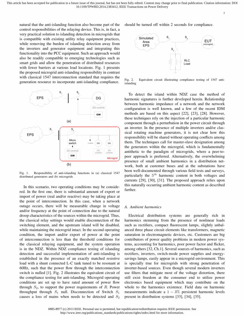
Typical spectra of harmonic components of voltages mea-sured from the experimental UW-Madison laboratory scalemicrogrid test-bed at S2 is illustrated in Fig. 4 when S1 is
closed (Grid connected) and S1 is open (Autonomous). Thesemeasurements were obtained under the scenario where themicrogrid and the utility grid are connected with no powerexchange through the link. In case of an unintentional island-ing event, the undetectable changes in other variables such asvoltage or frequency integrate this loading scenario within theNDZ of classical IDMs. As may be observed, the two con-ditions show significant differences, particularly with respectto the 5th harmonic. While such discrepancies are a complexfunction of network conditions, they are nevertheless presentin any system. Protective relays with harmonic measurementfunctions may be programmed to detect these conditions andprovide a disconnecting function to appropriately meet safetystandards without resorting to any perturbing actions withinany of the internal microgrid components.
120 180 240 300 360 420 4800
0.5
1
1.5
2
2.5
3
3.5
4
Frequency (Hz)
Volta
ge (%
)
Voltage harmonics at the PCC
Grid−connected modeAutonomous mode
Fig. 4. Typical harmonic voltages under grid-connected and autonomousmodes
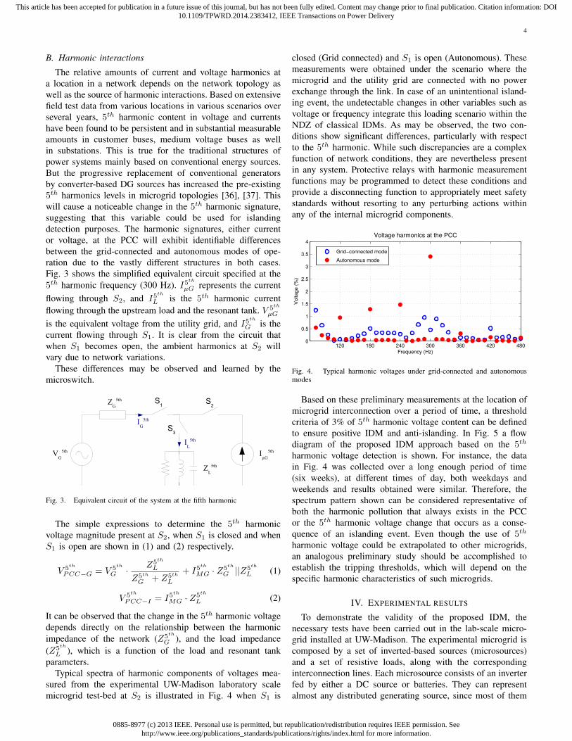
Based on these preliminary measurements at the location ofmicrogrid interconnection over a period of time, a thresholdcriteria of 3% of 5th harmonic voltage content can be definedto ensure positive IDM and anti-islanding. In Fig. 5 a flowdiagram of the proposed IDM approach based on the 5th
harmonic voltage detection is shown. For instance, the datain Fig. 4 was collected over a long enough period of time(six weeks), at different times of day, both weekdays andweekends and results obtained were similar. Therefore, thespectrum pattern shown can be considered representative ofboth the harmonic pollution that always exists in the PCCor the 5th harmonic voltage change that occurs as a conse-quence of an islanding event. Even though the use of 5th
harmonic voltage could be extrapolated to other microgrids,an analogous preliminary study should be accomplished toestablish the tripping thresholds, which will depend on thespecific harmonic characteristics of such microgrids.
IV. EXPERIMENTAL RESULTS
To demonstrate the validity of the proposed IDM, thenecessary tests have been carried out in the lab-scale micro-grid installed at UW-Madison. The experimental microgrid iscomposed by a set of inverted-based sources (microsources)and a set of resistive loads, along with the correspondinginterconnection lines. Each microsource consists of an inverterfed by either a DC source or batteries. They can representalmost any distributed generating source, since most of them
0885-8977 (c) 2013 IEEE. Personal use is permitted, but republication/redistribution requires IEEE permission. Seehttp://www.ieee.org/publications_standards/publications/rights/index.html for more information.
This article has been accepted for publication in a future issue of this journal, but has not been fully edited. Content may change prior to final publication. Citation information: DOI10.1109/TPWRD.2014.2383412, IEEE Transactions on Power Delivery
5
Fig. 5. Flow diagram of the proposed IDM
are connected to the utility grid by means of an inverter.A simplified schematic of the laboratory scale microgrid isshown in Fig. 6.
Fig. 6. Simplified diagram of the laboratory scale microgrid
The microsources have a rated power of 15 kW peak.The resonant RLC load required to perform the test methodvalidation has been calculated according to the expressionsappearing in the IEEE 1547.1 standard.
Switch S2 is in series with a back-to-back connected thyris-tor bridge that acts as a solid-state power switch (called S2
′
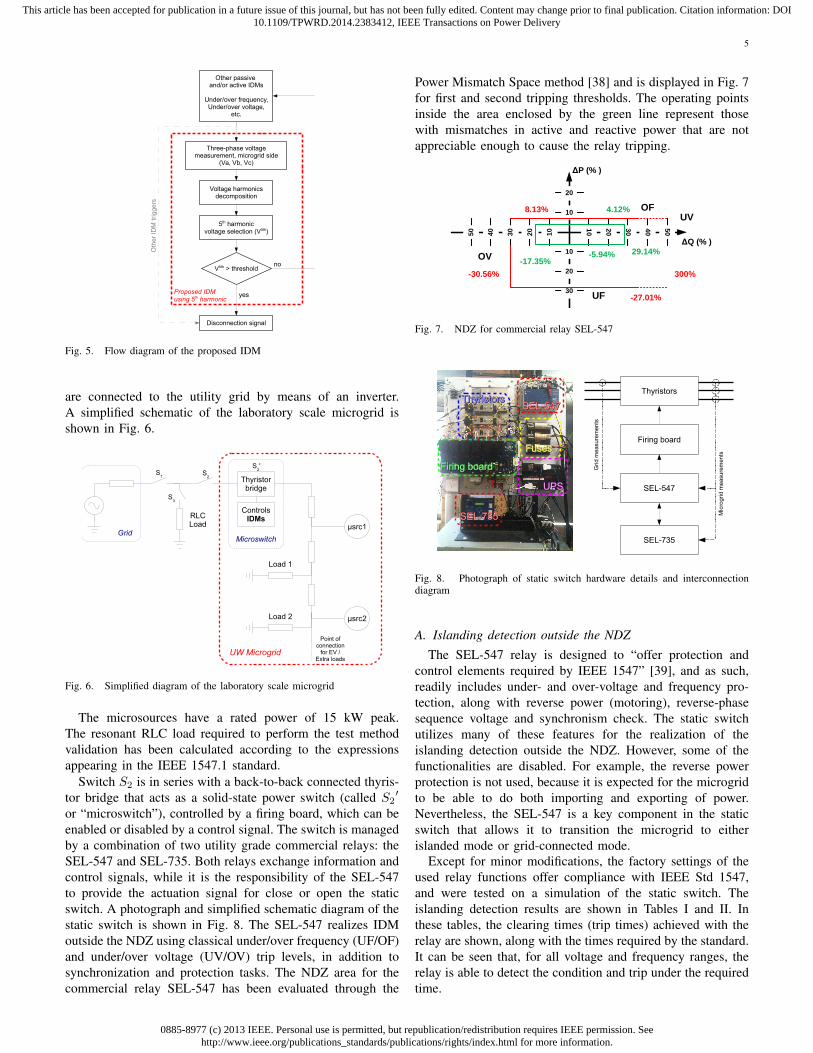
or “microswitch”), controlled by a firing board, which can beenabled or disabled by a control signal. The switch is managedby a combination of two utility grade commercial relays: theSEL-547 and SEL-735. Both relays exchange information andcontrol signals, while it is the responsibility of the SEL-547to provide the actuation signal for close or open the staticswitch. A photograph and simplified schematic diagram of thestatic switch is shown in Fig. 8. The SEL-547 realizes IDMoutside the NDZ using classical under/over frequency (UF/OF)and under/over voltage (UV/OV) trip levels, in addition tosynchronization and protection tasks. The NDZ area for thecommercial relay SEL-547 has been evaluated through the
Power Mismatch Space method [38] and is displayed in Fig. 7for first and second tripping thresholds. The operating pointsinside the area enclosed by the green line represent thosewith mismatches in active and reactive power that are notappreciable enough to cause the relay tripping.
4.12%
29.14%
ΔP (% )
ΔQ (% )
10
20
10
20
30
10
20
30
40
50
10
20
30
40
50
8.13%
-30.56%
-27.01%
300%
-5.94%-17.35%
OF
UF
OV
UV
Fig. 7. NDZ for commercial relay SEL-547
Firing boardFiring board
ThyristorsThyristorsSEL-547SEL-547
SEL-735SEL-735
FusesFuses
UPSUPS
Fig. 8. Photograph of static switch hardware details and interconnectiondiagram
A. Islanding detection outside the NDZThe SEL-547 relay is designed to “offer protection and
control elements required by IEEE 1547” [39], and as such,readily includes under- and over-voltage and frequency pro-tection, along with reverse power (motoring), reverse-phasesequence voltage and synchronism check. The static switchutilizes many of these features for the realization of theislanding detection outside the NDZ. However, some of thefunctionalities are disabled. For example, the reverse powerprotection is not used, because it is expected for the microgridto be able to do both importing and exporting of power.Nevertheless, the SEL-547 is a key component in the staticswitch that allows it to transition the microgrid to eitherislanded mode or grid-connected mode.
Except for minor modifications, the factory settings of theused relay functions offer compliance with IEEE Std 1547,and were tested on a simulation of the static switch. Theislanding detection results are shown in Tables I and II. Inthese tables, the clearing times (trip times) achieved with therelay are shown, along with the times required by the standard.It can be seen that, for all voltage and frequency ranges, therelay is able to detect the condition and trip under the requiredtime.
0885-8977 (c) 2013 IEEE. Personal use is permitted, but republication/redistribution requires IEEE permission. Seehttp://www.ieee.org/publications_standards/publications/rights/index.html for more information.
This article has been accepted for publication in a future issue of this journal, but has not been fully edited. Content may change prior to final publication. Citation information: DOI10.1109/TPWRD.2014.2383412, IEEE Transactions on Power Delivery
6
TABLE ISEL-547 ISLANDIG DETECTION RESULTS: VOLTAGE
Voltage Testing Average trip IEEE Std 1547Range voltage [%] time [s] requirement [s]
V < 50% 45.45 0.1145 0.1650% ≤ V < 88% 75.76 1.9430 2.00
110% < V < 120% 111.36 0.9470 1.00V ≥ 120% 121.21 0.1170 0.16
TABLE IISEL-547 ISLANDIG DETECTION RESULTS: FREQUENCY
Frequency Testing Average trip IEEE Std 1547range frequency [Hz] time [s] requirement [s]
>60.5 Hz 61 0.0940 0.16<{59.8-57.0} Hz 58 1.9430 0.16–300†
<57 Hz 56 0.1010 0.16† Adjustable as per IEEE Std 1547-2003, §4.2.4
It is important to remind that, as for the IEEE Std 1547,the ranges of voltages and frequencies stated are considered“abnormal conditions”. For the purposes of the islandingdetection, these conditions are those under which the staticswitch should isolate the microgrid from the utility grid, andwould not necessarily shut down the microgrid. However,it will be the responsibility of the microgrid operator tomaintain the power quality within the microgrid, which coulduse the same voltage and frequency indices already usedfor islanding detection. For example, the abnormal frequencyrange (59.8–57.0) Hz has an adjustable clearing time, and theuse of frequency droop will inevitably drop the frequencyunder certain conditions, even though this operation modemight be desirable. In the same fashion, a certain voltage dropat the static switch does not necessarily mean that, within themicrogrid, the voltages are outside the desired safe operatingbands. It will be the task of other relays, such as the SEL-735,to monitor the power quality conditions within the microgrid.
B. Islanding detection inside the NDZ
The SEL-735 relay has various power quality measurementcapabilities which enable IDM using harmonic content resolu-tion. Phase voltages at the terminals of S2
′ are measured andmonitored at every cycle. These voltages are decomposed intheir harmonic spectra by the SEL-735. Subsequently, the 5th
harmonic voltage estimate is compared with the 5th harmonicthreshold fixed in the power quality relay settings (set to be3% on the basis of a priori background measurements, and perthe minimum available threshold of action by SEL-735). If thelevel measured is over the established threshold, a trip signalis sent to SEL-547 relay. SEL-547 relays this information toopen the static switch for full disconnection of the microgridfrom any unintended island to upstream loads. The operationof the IDM outside the NDZ and inside the NDZ has beenconducted using extensive measurements.
Various tests have been realized for several cases withvariable power flows situations. In each case, the powerbalance from the utility grid and from the microgrid is set to bedifferent. This approach is an extension to the classical IEEEStd 1547, in which the power direction is only flowing from
the distributed generation source to the utility grid. Severalscenarios for the microgrid have been defined as follows:
1) Microgrid supports RLC load, and exports excess powerto grid.
2) Microgrid supports RLC load partially, and utility gridsupports balance of power to meet RLC load require-ments.
3) Microgrid supports RLC load completely and exports nopower to the grid through S1.
4) Microgrid imports net power from the utility grid, whichalso supports RLC load.
5) Microgrid exchanges zero net power through S2, whileutility grid supports RLC load.
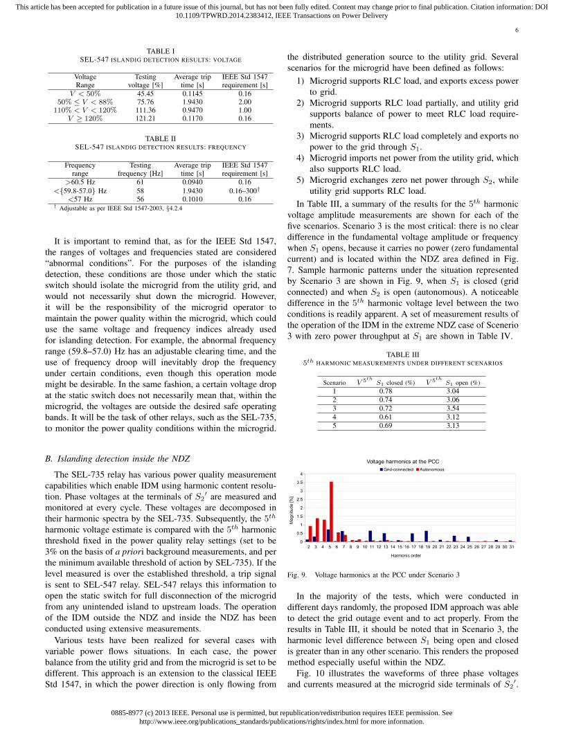
In Table III, a summary of the results for the 5th harmonicvoltage amplitude measurements are shown for each of thefive scenarios. Scenario 3 is the most critical: there is no cleardifference in the fundamental voltage amplitude or frequencywhen S1 opens, because it carries no power (zero fundamentalcurrent) and is located within the NDZ area defined in Fig.7. Sample harmonic patterns under the situation representedby Scenario 3 are shown in Fig. 9, when S1 is closed (gridconnected) and when S2 is open (autonomous). A noticeabledifference in the 5th harmonic voltage level between the twoconditions is readily apparent. A set of measurement results ofthe operation of the IDM in the extreme NDZ case of Scenerio3 with zero power throughput at S1 are shown in Table IV.
TABLE III5th HARMONIC MEASUREMENTS UNDER DIFFERENT SCENARIOS
Scenario V 5th S1 closed (%) V 5th S1 open (%)1 0.78 3.042 0.74 3.063 0.72 3.544 0.61 3.125 0.69 3.13
Fig. 9. Voltage harmonics at the PCC under Scenario 3
In the majority of the tests, which were conducted indifferent days randomly, the proposed IDM approach was ableto detect the grid outage event and to act properly. From theresults in Table III, it should be noted that in Scenario 3, theharmonic level difference between S1 being open and closedis greater than in any other scenario. This renders the proposedmethod especially useful within the NDZ.
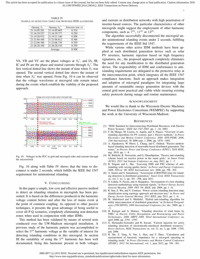
Fig. 10 illustrates the waveforms of three phase voltagesand currents measured at the microgrid side terminals of S2
′.
0885-8977 (c) 2013 IEEE. Personal use is permitted, but republication/redistribution requires IEEE permission. Seehttp://www.ieee.org/publications_standards/publications/rights/index.html for more information.
This article has been accepted for publication in a future issue of this journal, but has not been fully edited. Content may change prior to final publication. Citation information: DOI10.1109/TPWRD.2014.2383412, IEEE Transactions on Power Delivery
7
TABLE IVSAMPLE OF DETECTION TIMES FOR PROPOSED IDM ALGORITHM
Opening S1 Opening S2′ Detection time (s)
21:14:05.281 21:14:05.605 0.32421:16:39.527 21:16:39.777 0.25021:19:20.932 21:19:21.140 0.20821:21:04.446 21:21:04.812 0.36621:22:06.386 21:22:06.736 0.35021:26:28.160 21:26:28.510 0.350
Average 0.308
VA, VB and VC are the phase voltages at S2′, and IA, IB,
IC and IN are the phase and neutral currents through S2′. The
first vertical dotted line shows the instant of time when S1 wasopened. The second vertical dotted line shows the instant oftime when S2
′ was opened. From Fig. 10 it can be observedthat the voltage waveforms at microgrid side remain intactduring the events which establish the viability of the proposedapproach.
0 0.05 0.1 0.15 0.2 0.25 0.3 0.35 0.4 0.45 0.5−10
−5
0
5
10
Time [s]
IA[A]
IB[A]
IC[A]
IN[A]
0 0.05 0.1 0.15 0.2 0.25 0.3 0.35 0.4 0.45 0.5−200
−100
0
100
200Voltage and current at static switch (microgrid side)
VA[V]
VB[V]
VC[V]
Unintentionalislanding occurs
IDM acts and static switch opens
Fig. 10. Voltages in the PCC in grid and microgrid sides and currents throughthe microswitch
Fig. 10 along with Table IV shows that the time to dis-connect is under 2 seconds, which fulfills the IEEE Std 1547requirement for unintentional islanding.
V. CONCLUSIONS
In this paper a simple, low-cost and effective passive methodto detect an islanding situation in microgrids has been pre-sented. It is based on the differences produced in the harmonicvoltage content before and after the loss of mains event atthe point of common coupling. As opposed to other passivetechniques, it presents the great advantage of being useful tocover all P-Q scenarios, completely eliminating non-detectionzones when used in conjunction with other IDMs.
This method has been validated by means of several testsconducted over the UW-Madison microgrid installation. Aprevious study of the harmonic pattern was accomplished toselect the 5th harmonic voltage as the variable of interest fordetecting islanding conditions in this microgrid. In sectionIII the suitability of using the 5th harmonic has been welldocumented, being this harmonic present in both voltages
and currents in distribution networks with high penetration ofinverter-based sources. The particular characteristics of othermicrogrids might suggest the employment of other harmoniccomponents, such as 7th, 11th or 13th.
The algorithm successfully disconnected the microgrid un-der unintentional islanding events under 2 seconds, fulfillingthe requirements of the IEEE Std 1547.
While various other active IDM methods have been ap-plied at each distributed generation device such as solarPV inverters, harmonic injection based on high frequencysignatures, etc., the proposed approach completely eliminatesthe need for any modification to the distributed generationdevice. The responsibility of IDM and conformance to anti-islanding requirements are delegated to the protective relay atthe interconnection point, which integrates all the IEEE 1547compliance functions. Such an approach makes integrationand adoption of microgrid paradigms for integrating largeamounts of sustainable energy generation devices with thecentral grid more practical and viable while ensuring existingsafety protocols during outage and routine maintenance.
ACKNOWLEDGMENT
We would like to thank to the Wisconsin Electric Machinesand Power Electronics Consortium (WEMPEC) by supportingthe work at the University of Wisconsin-Madison.
REFERENCES
[1] “IEEE Standard for Interconnecting Distributed Resources with ElectricPower Systems,” IEEE Std 1547-2003, pp. 1 –16, 2003.
[2] F. De Mango, M. Liserre, A. Aquila, and A. Pigazo, “Overview of anti-islanding algorithms for PV systems. part i: Passive methods,” in PowerElectronics and Motion Control Conference, 2006. EPE-PEMC 2006.12th International, 30 2006-sept. 1 2006, pp. 1878 –1883.
[3] A. Aljankawey, W. Morsi, L. Chang, and C. Diduch, “Passive method-based islanding detection of renewable-based distributed generation: Theissues,” in Electric Power and Energy Conference (EPEC), 2010 IEEE,aug. 2010, pp. 1 –8.
[4] M. Bakhshi, R. Noroozian, and G. Gharehpetian, “Passive anti-islandingscheme based on reactive power in the smart grids,” in Smart Grids(ICSG), 2012 2nd Iranian Conference on, may 2012, pp. 1 –7.
[5] B. Singam and L. Hui, “Assessing SMS and PJD schemes of anti-islanding with varying quality factor,” in Power and Energy Conference,2006. PECon ’06. IEEE International, nov. 2006, pp. 196 –201.
[6] A. Samui and S. Samantaray, “Assessment of ROCPAD relay for island-ing detection in distributed generation,” Smart Grid, IEEE Transactionson, vol. 2, no. 2, pp. 391 –398, june 2011.
[7] N. Lidula, N. Perera, and A. Rajapakse, “Investigation of a fast islandingdetection methodology using transient signals,” in Power Energy SocietyGeneral Meeting, 2009. PES ’09. IEEE, july 2009, pp. 1 –6.
[8] R. Sun, Z. Wu, and V. Centeno, “Power system islanding detection amp;identification using topology approach and decision tree,” in Power andEnergy Society General Meeting, 2011 IEEE, july 2011, pp. 1 –6.
[9] M. Abdolrasol and S. Mekhilef, “Hybrid anti-islanding algorithm forutility interconnection of distributed generation,” in Technical Postgrad-uates (TECHPOS), 2009 International Conference for, dec. 2009, pp. 1–5.
[10] H. Karegar and A. Shataee, “Islanding detection of wind farms byTHD,” in Electric Utility Deregulation and Restructuring and PowerTechnologies, 2008. DRPT 2008. Third International Conference on,april 2008, pp. 2793 –2797.
[11] G. Hernandez-Gonzalez and R. Iravani, “Current injection for activeislanding detection of electronically-interfaced distributed resources,”Power Delivery, IEEE Transactions on, vol. 21, no. 3, pp. 1698 –1705,july 2006.
[12] H. Shi, Z. Yang, X. Yue, L. Hou, and F. Zhuo, “Calculation andmeasurement of harmonic impedance for a microgrid operating inislanding mode,” in Power Electronics and Motion Control Conference(IPEMC), 2012 7th International, vol. 1, june 2012, pp. 356 –361.
0885-8977 (c) 2013 IEEE. Personal use is permitted, but republication/redistribution requires IEEE permission. Seehttp://www.ieee.org/publications_standards/publications/rights/index.html for more information.
This article has been accepted for publication in a future issue of this journal, but has not been fully edited. Content may change prior to final publication. Citation information: DOI10.1109/TPWRD.2014.2383412, IEEE Transactions on Power Delivery
8
[13] F. Liu, Y. Kang, Y. Zhang, S. Duan, and X. Lin, “Improved SMSislanding detection method for grid-connected converters,” RenewablePower Generation, IET, vol. 4, no. 1, pp. 36 –42, january 2010.
[14] H. Zeineldin and M. Salama, “Impact of load frequency dependenceon the NDZ and performance of the SFS islanding detection method,”Industrial Electronics, IEEE Transactions on, vol. 58, no. 1, pp. 139–146, jan. 2011.
[15] D. Velasco, C. Trujillo, G. Garcera, and E. Figueres, “An active anti-islanding method based on phase-PLL perturbation,” Power Electronics,IEEE Transactions on, vol. 26, no. 4, pp. 1056 –1066, april 2011.
[16] M. Ciobotaru, V. Agelidis, R. Teodorescu, and F. Blaabjerg, “Accurateand less-disturbing active antiislanding method based on PLL forgrid-connected converters,” Power Electronics, IEEE Transactions on,vol. 25, no. 6, pp. 1576 –1584, june 2010.
[17] A. Massoud, K. Ahmed, S. Finney, and B. Williams, “Harmonicdistortion-based island detection technique for inverter-based distributedgeneration,” Renewable Power Generation, IET, vol. 3, no. 4, pp. 493–507, december 2009.
[18] J. Lee, “Islanding Detection Methods for Microgrids,” Master’s thesis,University of Wisconsin-Madison, USA, 2010.
[19] P. Mahat, Z. Chen, and B. Bak-Jensen, “Review of islanding detectionmethods for distributed generation,” in Electric Utility Deregulationand Restructuring and Power Technologies, 2008. DRPT 2008. ThirdInternational Conference on, april 2008, pp. 2743 –2748.
[20] L. Lopes and Y. Zhang, “Islanding detection assessment of multi-invertersystems with active frequency drifting methods,” Power Delivery, IEEETransactions on, vol. 23, no. 1, pp. 480 –486, jan. 2008.
[21] M. Xue, F. Liu, Y. Kang, and Y. Zhang, “Investigation of active islandingdetection methods in multiple grid-connected converters,” in PowerElectronics and Motion Control Conference, 2009. IPEMC ’09. IEEE6th International, may 2009, pp. 2151 –2154.
[22] S. Patthamakunchai, M. Konghirun, and W. Lenwari, “An anti-islandingfor multiple photovoltaic inverters using harmonic current injections,” inElectrical Engineering/Electronics, Computer, Telecommunications andInformation Technology (ECTI-CON), 2012 9th International Confer-ence on, may 2012, pp. 1 –4.
[23] L. Jun, H. Xue-liang, C. Xiao-hu, X. Miao, and X. Wen, “Two islandingdetection circuits based on the impedance variation for the micro-grid,”in Power Electronics for Distributed Generation Systems (PEDG), 20102nd IEEE International Symposium on, june 2010, pp. 859 –863.
[24] X. Wang, C. Zhang, W. Zhao, and X. Mu, “Non-devastating islandingdetection for micro-grid based on mathematical statistics,” in PowerElectronics and ECCE Asia (ICPE ECCE), 2011 IEEE 8th InternationalConference on, 30 2011-june 3 2011, pp. 2650 –2657.
[25] Y.-G. Lee, H.-W. Lee, Y.-H. Kim, T.-Y. Zheng, and Y.-C. Kang,“Islanding detection for a micro-grid based on the active and reactivepower in the time domain,” in Advanced Power System Automation andProtection (APAP), 2011 International Conference on, vol. 3, oct. 2011,pp. 1956 –1961.
[26] H. Bitaraf, M. Sheikholeslamzadeh, A. M. Ranjbar, and B. Mozafari, “Anovel SVM approach of islanding detection in micro grid,” in InnovativeSmart Grid Technologies - Asia (ISGT Asia), 2012 IEEE, may 2012, pp.1 –5.
[27] J. Li, X. Li, Y. Zhang, S. Hao, and Y. Jia, “A centralized injectionmethod for islanding detection in micro-grids,” in Power and EnergyEngineering Conference (APPEEC), 2012 Asia-Pacific, march 2012, pp.1 –3.
[28] D. Reigosa, F. Briz, C. Blanco, P. Garcia, and J. Guerrero, “Activeislanding detection using high frequency signal injection,” in EnergyConversion Congress and Exposition (ECCE), 2011 IEEE, sept. 2011,pp. 2183 –2190.
[29] A. Emanuel, J. Orr, D. Cyganski, and E. M. Gulachenski, “A surveyof harmonic voltages and currents at distribution substations,” PowerDelivery, IEEE Transactions on, vol. 6, no. 4, pp. 1883–1890, 1991.
[30] ——, “A survey of harmonic voltages and currents at the customer’sbus,” Power Delivery, IEEE Transactions on, vol. 8, no. 1, pp. 411–421,1993.
[31] I. Nejdawi, A. Emanuel, D. Pileggi, M. J. Corridori, and R. D. Ar-chambeault, “Harmonics trend in ne usa: a preliminary survey,” PowerDelivery, IEEE Transactions on, vol. 14, no. 4, pp. 1488–1494, 1999.
[32] M. A. S. M. Ewald F. Fuchs, Power Quality in Power Systems andElectrical Machines. Elsevier Academic Press, 2008.
[33] J. F. G. Cobben, W. L. Kling, and J. M. A. Myrzik, “Power qualityaspects of a future micro grid,” in Future Power Systems, 2005 Interna-tional Conference on, 2005, pp. 5 pp.–5.
[34] S. Bhattacharyya, J. F. G. Cobben, and W. Kling, “Harmonic currentpollution in a low voltage network,” in Power and Energy SocietyGeneral Meeting, 2010 IEEE, 2010, pp. 1–8.
[35] P. Lauwers, C. Pirenne, P. Sommereyns, W. Vancoetsem, E. De Jaeger,and M. De Witte, “Power quality monitoring in belgian distributionnetworks,” in Electricity Distribution, 2005. CIRED 2005. 18th Interna-tional Conference and Exhibition on, 2005, pp. 1–6.
[36] A. Kahrobaeian and Y.-R. Mohamed, “Interactive distributed generationinterface for flexible micro-grid operation in smart distribution systems,”Sustainable Energy, IEEE Transactions on, vol. 3, no. 2, pp. 295–305,April 2012.
[37] V. Pandi, H. Zeineldin, and W. Xiao, “Allowable dg penetration levelconsidering harmonic distortions,” in IECON 2011 - 37th Annual Con-ference on IEEE Industrial Electronics Society, Nov 2011, pp. 814–818.
[38] Z. Ye, A. Kolwalkar, Y. Zhang, P. Du, and R. Walling, “Evaluationof anti-islanding schemes based on nondetection zone concept,” PowerElectronics, IEEE Transactions on, vol. 19, no. 5, pp. 1171–1176, Sept2004.
[39] SEL-547 - Utility-Grade Protection for Distributed Generation,Schweitzer Engineering Laboratories, Inc. (SEL), 2013. [Online]. Avail-able: https://www.selinc.com/WorkArea/DownloadAsset.aspx?id=2882
Julia Merino (IEEE Student Member) was born inSpain. She received the Dipl. degree in industrialengineering and the M.S. degree in electrical engi-neering from the Technical University of Madrid,Madrid, Spain, in 2010 and 2012, respectively. Sheis currently working towards the Ph.D degree. She isalso involved in the Smart Grids and Energy StorageArea in Tecnalia R&I Corporation. Ms. Merino is theactual Vice Chair of the IEEE WIE Spanish Section.
Patricio Mendoza-Araya (IEEE Member) was bornin Chile. He received the B.Sc. degree in elec-trical engineering from the University of Chile in2007, and the Ph.D. degree from the Universityof Wisconsin-Madison in 2014. He is currently aninstructor in the Electrical Engineering Departmentof the University of Chile. His research field ispower electronics on microgrids, electric vehiclesand renewable energies.
Giri Venkataramanan (M’92-SM’06) received theB.Sc. degree in electrical engineering from the Go-vernment College of Technology, Coimbatore, India,the M.Sc. degree from the California Institute ofTechnology, Pasadena, and the Ph.D. degree fromthe University of Wisconsin, Madison. After teach-ing electrical engineering at Montana State Univer-sity, Bozeman, he returned to University of Wiscon-sin, Madison, as a Faculty Member in 1999, wherehe continues to direct research in various areas ofelectronic power conversion as an Associate Director
of the Wisconsin Electric Machines and Power Electronics Consortium(WEMPEC). He holds four U.S. patents and has published a number of papers.
Mustafa Baysal was born in Istanbul, Turkey in1976. He received B.Sc., M.Sc. and Ph.D. degreesall from Yildiz Technical University,Department ofElectrical Engineeringin 1998, 2001 and 2008, re-spectively. Currently, he is an Assistant Professor inthe Yildiz Technical University. His current researchinterests include microgrids, smart grids, distributedgeneration, power quality and application of powerelectronics to power systems.