iso-80 instruction manual precision instruments/is0-80.pdfiso-80 world precision instruments 5...
TRANSCRIPT
ISO-80Isolated Differential Amplifier
INSTRUCTION MANUAL
Serial No._____________________
102810
World Precision Instruments
ww
w.w
pii
nc.
com

ISO-80
WORLD PRECISION INSTRUMENTS iii
Copyright © 2010 by World Precision Instruments, Inc. All rights reserved. No part of this publication may be reproduced or translated into any language, in any form, without prior written permission of World Precision Instruments, Inc.
CONTENTSABOUT THIS MANUAL ............................................................................................................................... 1INTRODUCTION ............................................................................................................................................ 2INSTRUMENT DESCRIPTION .................................................................................................................... 3
Parts List ..................................................................................................................................................... 3Unpacking ................................................................................................................................................. 4Description ................................................................................................................................................ 4
ISO-80 Base Unit - Face ................................................................................................................... 4ISO-80 Base Unit - Right Side ....................................................................................................... 5ISO-80 Base Unit - Left Side ........................................................................................................... 5ISO80P Probe ..................................................................................................................................... 5
OPERATING INSTRUCTIONS ................................................................................................................... 6Amplifying Mode ..................................................................................................................................... 6
Filter Settings ....................................................................................................................................... 6Output ................................................................................................................................................... 7Modes of Amplification ................................................................................................................... 8Measuring Electrode Impedance: the Z Mode ......................................................................10
Generating Marker Current: the Marker Mode ..........................................................................11Using the ISO-80 Internal Current Generator ........................................................................11Using the ISO-80 External Current Control Input .................................................................11Maximum Current Level ...............................................................................................................12
INSTRUMENT MAINTENANCE ...............................................................................................................13Recharge the Batteries ........................................................................................................................13Replacement Parts ................................................................................................................................13
ACCESSORIES ...............................................................................................................................................14SPECIFICATIONS ..........................................................................................................................................15APPENDIX A: WIRING CONFIGURATIONS ........................................................................................16
Dual Metal Electrode (Add two metal electrodes) .......................................................................... 16Dual Metal Electrode (Add two metal electrodes) .......................................................................... 16Single Metal Electrode (Add single metal electrode) ...................................................................... 17Dual Micropipette (Add 1 mm glass micropipettes) ....................................................................... 17Single Micropipette (Add 1 mm glass micropipette) ..................................................................... 17
WARRANTY ..................................................................................................................................................20Claims and Returns ..............................................................................................................................20

ISO-80
WORLD PRECISION INSTRUMENTSiv

ISO-80
WORLD PRECISION INSTRUMENTS 1
ABOUT THIS MANUAL
The following symbols are used in this guide:
This symbol indicates a CAUTION. Cautions warn against actions that can cause damage to equipment. Please read these carefully.
This symbol indicates a WARNING. Warnings alert you to actions that can cause personal injury or pose a physical threat. Please read these carefully.
NOTES and TIPS contain helpful information.
Fig. 1 — ISO-80
ISO-80
WORLD PRECISION INSTRUMENTS2
INTRODUCTION
The ISO-80 is a high performance, isolated, differential amplifier designed for extracellular recording of nerve/muscle cell action potentials in vitro and in vivo. Other functions include measuring electrode impedance and generating current for applications such as tissue marking, stimulation and electrode cleaning. It is a battery-powered, low-noise, AC-coupled differential amplifier electrically isolated from main power and ground lines.
The ISO-80 is provided with a remote headstage (1m cable) which incorporates an electrode impedance test function and a constant current stimulator. The constant current stimulator can be used for cell marking, stimulation or electrode cleaning.
Typical applications include measuring EMG, EEG, extracellular and action potentials. The ISO-80 is electro-magnetically shielded for improved noise rejection, and it employs both high pass and low pass filtering with gain from 100x to 10,000x.
ISO-80
WORLD PRECISION INSTRUMENTS 3
INSTRUMENT DESCRIPTION
Parts List• ISO-80 Amplifier
• ISO-80P Probe
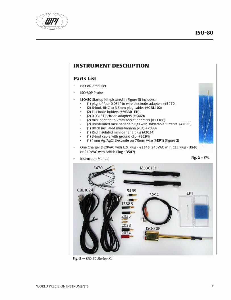
• ISO-80 Startup Kit (pictured in Figure 3) includes: • (1) pkg. of four 0.031" to wire electrode adapters (#5470)• (2) 6-foot, BNC to 3.5mm plug cables (#CBL102) • (2) Electrode holders (#M3301EH)• (2) 0.031" Electrode adapters (#5469)• (2) mini-banana to 2mm socket adapters (#13388)• (2) uninsulated mini-banana plugs with solderable turrents (#2035) • (1) Black insulated mini-banana plug (#2033) • (1) Red Insulated mini-banana plug (#2034) • (1) 3-foot cable with ground clip (#3294) • (1) 1mm Ag/AgCl Electrode on 70mm wire (#EP1) (Figure 2)
• One Charger (120VAC with U.S. Plug - #3545, 240VAC with CEE Plug - 3546 or 240VAC with British Plug - 3547)
• Instruction Manual
5470
CBL102
M3301EH
5469
13388
2035
2033
2034
3294
ISO-80P
EP1
Fig. 3 — ISO-80 Startup Kit
Fig. 2 – EP1.

ISO-80
WORLD PRECISION INSTRUMENTS4
UnpackingUpon receipt of this instrument, make a thorough inspection of the contents and check for possible damage. Missing cartons or obvious damage to cartons should be noted on the delivery receipt before signing. Concealed loss or damage should be reported at once to the carrier and an inspection requested. Please read the section entitled “Claims and Returns” on page 20 of this manual. Please call WPI Customer Service if any parts are missing.
Returns: Do not return any goods to WPI without obtaining prior approval (RMA # required) and instructions from WPI’s Returns Department. Goods returned (unauthorized) by collect freight may be refused. If a return shipment is necessary, use the original container. If the original container is not available, use a suitable substitute that is rigid and of adequate size. Wrap the instrument in paper or plastic surrounded with at least 100mm (four inches) of shock absorbing material. Please read the section entitled “Claims and Returns” on page 20 of this manual.
Description
ISO-80 Base Unit - FaceLabeled items on the Figure 3 (ISO-80 face plate) are described below.
Mode switch to choose amplification (AMP), electrode impedance measurement (Z) or tissue marking (Marker) mode.
Marker Amplitude dial controls the amount of current injected when using the Marker mode.
Digital LCD Display registers readings of 3.5 digits.
Output Polarity Select determines the polarity of the output. Generally, it is set to "+."
Power I/O toggle switch turns the meter on (I) and off (O).
Voltage Gain toggle switch controls the magnification of the amplifier.
High Filter toggle switch affects the high frequency cutoff.
Ground port for connecting a ground wire.
Probe Input port connection for the ISO80P.
Low Filter toggle switch determines the lower cut off frequency.
31 2 4
9
8 7 56
10
Fig. 4 – ISO-80, labeled.
ISO-80
WORLD PRECISION INSTRUMENTS 5
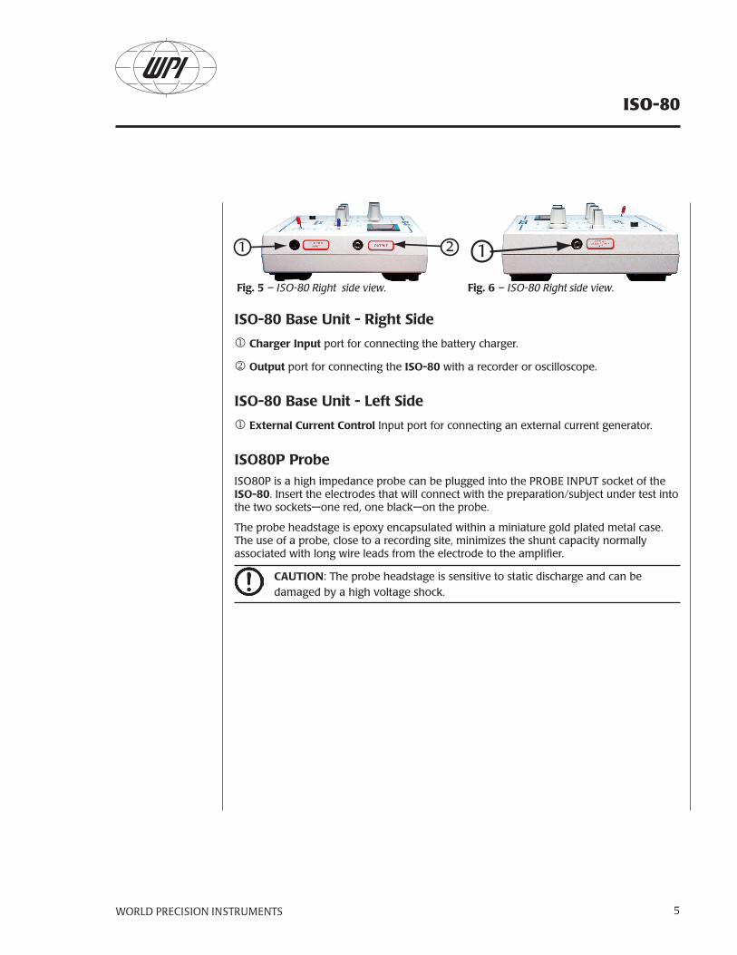
ISO-80 Base Unit - Right Side
Charger Input port for connecting the battery charger.
Output port for connecting the ISO-80 with a recorder or oscilloscope.
ISO-80 Base Unit - Left Side
External Current Control Input port for connecting an external current generator.
ISO80P ProbeISO80P is a high impedance probe can be plugged into the PROBE INPUT socket of the ISO-80. Insert the electrodes that will connect with the preparation/subject under test into the two sockets—one red, one black—on the probe.
The probe headstage is epoxy encapsulated within a miniature gold plated metal case. The use of a probe, close to a recording site, minimizes the shunt capacity normally associated with long wire leads from the electrode to the amplifier.
CAUTION: The probe headstage is sensitive to static discharge and can be damaged by a high voltage shock.
1 2 1
Fig. 5 – ISO-80 Right side view. Fig. 6 – ISO-80 Right side view.
ISO-80
WORLD PRECISION INSTRUMENTS6
OPERATING INSTRUCTIONS
The ISO-80 has three basic modes of operation, which are selected using the MODE switch on the upper left-hand side of the instrument:
• AMP—Voltage amplification. The amplified voltage is made available for external recording or data acquisition at the OUTPUT socket on the right-hand side of the instrument.
• Z—Electrode impedance measurement. Operation can monitored on the LCD, and the output is disabled.
• MARKER—Tissue marking. Operation can monitored on the LCD, and the output is disabled.
Amplifying ModeTo use the amplify mode, set the POWER switch to ON and the MODE switch to AMP. Modulate the level of amplification by using the VOLTAGE GAIN switch. The gain can be set to 100x, 1,000x, or 10,000x. WPI recommends beginning with 100x.
Filter SettingsThe amplifier can amplify voltages which vary at frequencies extending from 5-10 kHz. To set the frequency band of measurement, use the LOW FILTER and HIGH FILTER control knobs.
Low Filter
The LOW FILTER switch sets the lowest frequency signal to be amplified. For example, 5Hz is typical for ECG and EEG measurements. For nerve-action voltage amplification, 10Hz is normally used. Brain in vivo recordings, 300Hz is suitable. Always set the LOW FILTER to a frequency as high as possible. This reduces the risk of interference by low-frequency noise signals.
NOTE: The recording instrument must be able to receive signal frequencies at least as low as the LOW FILTER setting. For example, an oscilloscope must be set to its DC mode.
High Filter
The HIGH FILTER switch sets the highest frequency signal to be amplified. The higher the rate of variation of the measured signal, the faster the response required of the amplifier. The amplifier’s fastest response is at the 10KHz setting.
NOTE: The recording instrument must be able to handle signal frequencies at least as high the setting of the HIGH FILTER control.
NOTE: The wider the frequency band used, the greater the intrinsic electronic noise in all circuits. Larger bandwidth increases the intrinsic noise on recordings and the risk of

ISO-80
WORLD PRECISION INSTRUMENTS 7
interference by external signals. The frequency band is set by the LOW and HIGH FILTER controls. Always use the minimum band that produces acceptable quality recordings. For example, for ECG and EEG set the LOW FILTER to 5Hz and the HIGH FILTER to 0.1kHz.
OutputThe amplified signal is available at the OUTPUT jack on the right side of the ISO-80. Connect a recorder, oscilloscope or data acquisition system to this jack using the cable (WPI #CBL102) provided in the accessories pack. The polarity of the output can be set using the OUTPUT POLARITY SELECT toggle. In normal operational mode (for example, amplification), set this switch to “+.”
The maximum output available depends on the frequency of the amplified voltage signal. For signals of frequency above 30Hz, the full, AC-signal range output voltage of +10V (20V peak-to-peak (P-P)) is available. Below 30Hz the maximum available output decreases as the frequency decreases. The relationship is shown in Figure 7.
NOTE: To avoid error when measuring low frequency signals, set the amplification so that the maximum available output level is not exceeded. For example, the maximum available output at a frequency 10Hz is 12V P-P. With an input signal of 10mV P-P at 10Hz, the maximum setting of the VOLTAGE GAIN control would be 1000. This gives an output of 10V P-P. If the VOLTAGE GAIN is set to 10,000, the output is limited to 12V P-P, not 100V P-P.
To obtain extra gain low frequencies, adjust the controls on the recording device (for example, the data acquisition system) connected to the IS0 -80.
Fig. 7 — Maximum Output vs. FrequencyFrequency (Hz)
Max
. Ou
tpu
t V
olt
age
(P-P
) 2018
16
14
12
10
8
6
4
2
5 10 20 40

ISO-80
WORLD PRECISION INSTRUMENTS8
Modes of AmplificationSpecimen voltages may be amplified two ways—single-ended or differentially. Use minimum length of electrode leads to reduce the risk of interference. Screened leads also reduce susceptibility to electrical noise/mains-pickup. If there is a risk of external, electrical interference, use the differential method.
Single-Ended Amplification
Single-ended amplification is illustrated in Fig. 8. One electrode (the working electrode) is plugged into the red socket on the probe and connected to the test specimen. To complete the electrical circuit and to provide a return path for electrical current, a second electrode (the reference electrode) is connected to the black probe socket, which in turn is connected to the probe handle. The probe handle is the ground of the amplifier circuits—CIRCUIT GROUND. A short lead and a clip for the probe handle are provided for making this connection (WPI #3294).
Interference Effects
In all laboratories supplied with mains power, a risk of interference from signals flowing in the power lines exists. The interfering signals are usually at a frequency of 50-60Hz and are picked up by any electrical equipment in the area through a process of electromagnetic induction. If the measuring electrodes detect This signal, it will be amplified along with true input voltages and appear on the recordings. Whether this is significant or not depends upon the:
• Level of activity in the mains power lines
• Length of the input wires to the equipment
• Sensitivity of the measuring equipment
If it becomes a problem at the test site, set up the specimen and electrodes in a shielded enclosure that is connected to circuit ground (for example, a Faraday cage). Or, use the differential amplification mode.
Fig. 8 — Single-Ended Amplification
To ISO-80
micro-manipulator
ISO-80 probe
#5469 electrode adapter*
#2033connector*
metal microelectrode
specimen
red socket
EP1* or similarAg/AgCl half-cell
#3294 grounding wire & clip*Cut, strip, and secure the wires in #2033 connector.
*Part included with the ISO-80 Startup Kit

ISO-80
WORLD PRECISION INSTRUMENTS 9
Differential Amplification
When using differential amplification, electrodes from both the red and black sockets on the probe are connected to the specimen. See Fig. 9. The specimen must be connected to circuit ground via the probe handle. See Fig. 10 for an alternate setup where the second microelectrode is separately secured, allowing independent placement of the two electrodes. In either set-up, the difference between the voltages at the two electrodes is amplified. Local interference will be picked up on both electrodes, but in roughly similar amounts on each. By amplifying the voltage difference at the electrodes, these signals largely cancel out. If the interference in the area is particularly strong, and its
effect continues to be a problem after differential amplification, use a shielded enclosure.
Fig. 10 — Differential Amplification
*Parts included with the ISO-80 Startup Kit.
To ISO-80
micro-manipulator
micro-manipulator
ISO-80 probe*
#5469electrodeadapter*
#5470electrodeadapter*
#M3301electrodeholder*
metalmicroelectrode
redsocket specimen
EP1* or similarAg/AgCl half-cell
#3294 grounding wire & clip*
#2033 connector*
Fig. 9 — Differential Amplification
To ISO-80
micro-manipulator
ISO-80 probe
#5469 electrode adapters*
metal microelectrodes
specimen
EP1* or similarAg/AgCl half-cell
#3294 grounding wire & clip*
*Part included with the ISO-80 Startup Kit.

ISO-80
WORLD PRECISION INSTRUMENTS10
Measuring Electrode Impedance: the Z ModeTo check electrode impedances (100K-20MW) with the ISO-80, set the MODE switch set to Z. The ISO-80 supplies a small (20nA peak-to-peak) current, alternating at 300Hz, to the electrode connected to the red (non-inverting) input socket of the probe. A reference electrode completes the current path back to the CIRCUIT GROUND of the ISO-80. As the ISO-80 delivers current through the probe, an audible tone sounds. Electrode impedance is displayed on the ISO-80 LCD.
NOTE: The amplifier output is disabled in the Z mode, and no signal can seen.
Electrode impedance may be measured in situ (electrode and probe connected to the preparation) or in a special test set-up.
In Situ Measurement
Measurement in-situ is made in the normal recording set-ups, as shown in Figures 8, 9 and 10.
NOTE: In the differential amplification configuration, only the electrode in the red socket can be measured.
To make the measurement:
1. Verify that the POWER switch is ON
2. Set the MODE switch to Z.
3. Electrode impedance is then shown on the LCD. The audible tone ceases when the MODE switch is set to AMP.
Test Setup
The test set-up is shown in Fig 9.
1. Insert the test electrode into the red socket on the probe.
2. Connect the black socket to CIRCUIT GROUND by using the clip on the probe handle (WPI #3294) or the GND jack socket on the instru-ment panel.
3. Insert the electrode under test in a 150nM NaCl solution.
4. Insert the silver wire reference electrode provided in the startup kit (WPI #EP1) in the same solution and connect it to the CIRCUIT GROUND.
5. To make the measurement, verify that the POWER switch is at ON
Fig. 11 — Electrode Impedance Test
To ISO-80
ISO-80 probe
#5469 electrodeadapter*
#2033connector*
Cut, strip andsecure #3294wire in #2033
connector
metalmicroelectrodeunder test
150 mM NaCl
red socket
EP1* or similarAg/AgCl half-cell
#3294grounding
wire & clip*
*Part included with the ISO-80. Startup Kit.

ISO-80
WORLD PRECISION INSTRUMENTS 11
6. Set the MODE switch to Z.
7. Electrode impedance is then shown on the LCD. The audible tone ceases when the MODE switch is set to AMP.
Generating Marker Current: the Marker ModeMarker current passes through the red (non-inverting) input socket of the probe, then to the recording electrode in situ (the electrode and probe connected to the preparation). Either the single-ended (Figure 6) or differential (Figures 7 and 8) configuration may be used.
NOTE: In the differential amplification configuration, marker current only passes through the electrode in the red socket.
Marker current can be generated two ways. The first way uses the internal MARKER current generator facility built into the ISO-80 circuit design. The second way uses an external voltage source applied to the EXTERNAL CURRENT CONTROL INPUT.
NOTE: The current generated using the internal source is a DC current. That generated by an external source can be either AC or DC, depending on the source.
Using the ISO-80 Internal Current GeneratorMarker currents up to 20µA are available with the MODE switch set to MARKER. The magnitude of the current delivered is adjustable using the MARKER AMPLITUDE knob and is displayed on the LCD. An audible tone sounds the instrument delivers current.
To initiate current:
1. Verify that the POWER is ON.
2. Set the MODE switch to MARKER.
3. Set the MARKER AMPLITUDE control knob to 0.
4. Adjust the MARKER AMPLITUDE control to achieve the required current. The current value is displayed on the LCD.
Using the ISO-80 External Current Control InputCurrent may be controlled by an external voltage source using the EXTERNAL CURRENT CONTROL INPUT socket on the left side of the ISO-80 The actual current generated depends on the magnitude of the voltage applied. The scale factor used is 100mV = 1µA.
NOTE: The voltage applied must be within the range 0V to ±2 volts. The voltage may be either DC or an AC pulse, sine wave or other wave form.
1. Verify that the POWER is ON.
ISO-80
WORLD PRECISION INSTRUMENTS12
2. Set the MODE switch to MARKER.
3. The current value is displayed on the LCD.
NOTE: When using the External Input there is no electrical isolation.
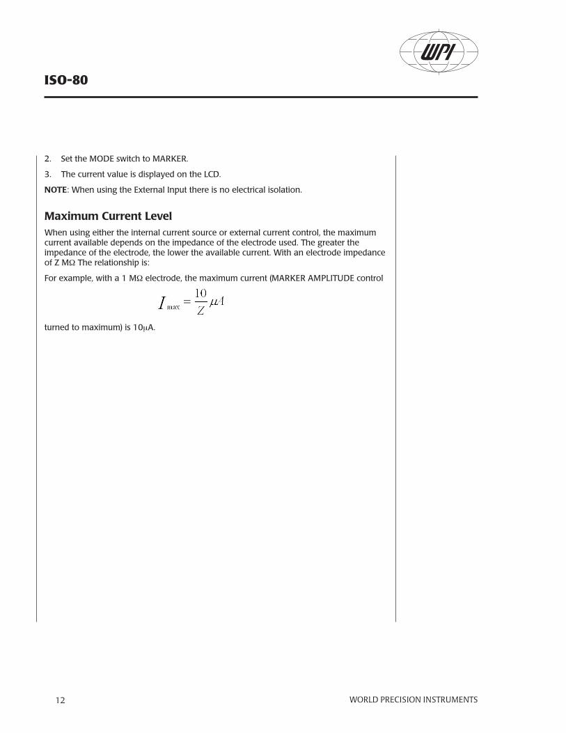
Maximum Current LevelWhen using either the internal current source or external current control, the maximum current available depends on the impedance of the electrode used. The greater the impedance of the electrode, the lower the available current. With an electrode impedance of Z MW The relationship is:
For example, with a 1 MW electrode, the maximum current (MARKER AMPLITUDE control
turned to maximum) is 10mA.

ISO-80
WORLD PRECISION INSTRUMENTS 13
INSTRUMENT MAINTENANCE
Recharge the BatteriesPower is provided by two 9V rechargeable batteries. With the ISO-80 in full, continuous operation, the batteries should last for 20 - 24 hours before recharging is necessary. When the batteries need to be recharged, LOW BAT displays on the LCD. Recharge batteries for 6 hours to restore them to full charge. If the batteries have been totally discharged (for example, after several months of shelf storage without use), 10 hours of charging may be necessary.
When recharging is necessary, plug the charger into the CHARGER INPUT socket on the right side of the ISO-80. Verify that the POWER is set to OFF/CHARGE.
Replacement PartsReplacement parts can be ordered using the part numbers in Table 1 (below). For additional accessories, refer to the Table 2 on page 14.Table 1: Replacement PartsWPI Part # DescriptionISO-80P Replacement Probe3414 9V NiMH Battery, each (2 required)

ISO-80
WORLD PRECISION INSTRUMENTS14
ACCESSORIES
Table 2 (below) lists accessory parts and provides a brief description of the parts.
Table 2: Accessory Parts
WPI Part # DescriptionCBL102 3.5 mm Phone plug-to-BNC CableEP1 Ag/AgCl pellet (70mm wire)MEH1S 1mm Pipette holder (2mm pin)MEH3SBW Mini banana pipette holderMEH8 Microelectrode holder, right angleM3301EH 2mm skt. to 0.031 skt. adapter2851 BNC-to-BNC Cable2033 Black Insulated Mini-Banana Plug2034 Red Insulated Mini-Banana Plug2035 Uninsulated Mini-Banana Plug2505 Electrode handle, 6.3mm3294 Ground clip with wire, 3' cable3484 Rack Mount Kit (for 2 DAM preamps)3485 Ringstand Mounting Kit5371 Cable, Low Noise (2mm pin to 2mm pin)5469 Metal Microelectrode Adapter for DAM80 (mini-banana plug to
0.031 in. (0.79 mm) socket)5470 2" Cable to 0.031 skt. 13388 Adapter, mini-banana plug to 2mm socket13620 Low-noise cable for microelectrode holder300040 2mm skt. to 2mm skt. Manipulator holder300102 Electrode Extension, 4-inch, 2mm to 0.031" metal electrode
ISO-80
WORLD PRECISION INSTRUMENTS 15
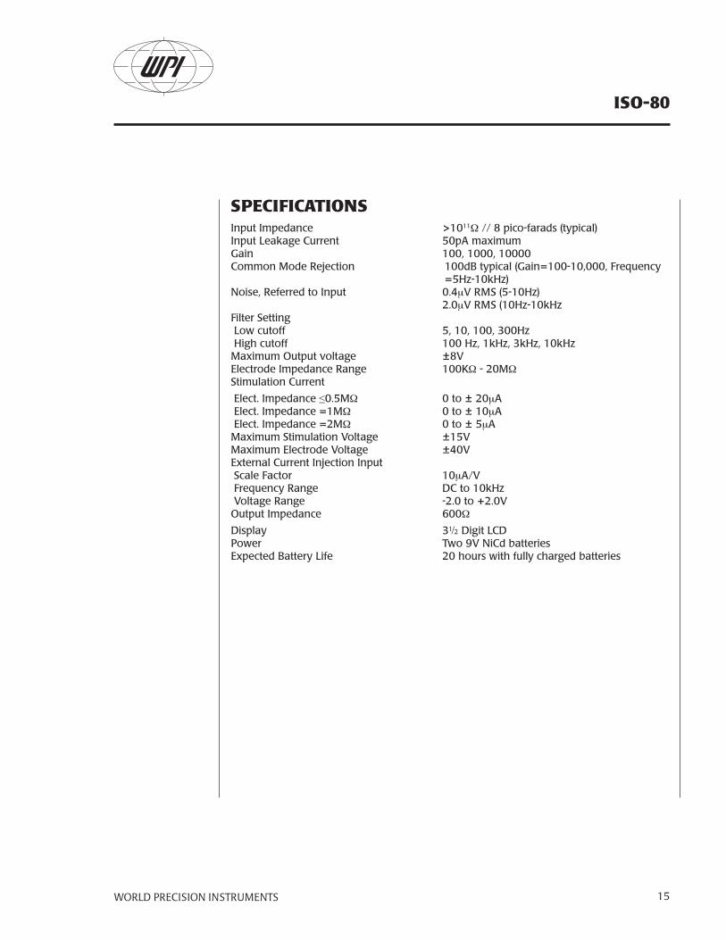
SPECIFICATIONSInput Impedance >1011W // 8 pico-farads (typical) Input Leakage Current 50pA maximum Gain 100, 1000, 10000 Common Mode Rejection 100dB typical (Gain=100-10,000, Frequency
=5Hz-10kHz)Noise, Referred to Input 0.4mV RMS (5-10Hz) 2.0mV RMS (10Hz-10kHz Filter Setting Low cutoff 5, 10, 100, 300Hz High cutoff 100 Hz, 1kHz, 3kHz, 10kHz Maximum Output voltage ±8VElectrode Impedance Range 100KW - 20MW Stimulation Current
Elect. Impedance ≤0.5MW 0 to ± 20mA Elect. Impedance =1MW 0 to ± 10mA Elect. Impedance =2MW 0 to ± 5mA Maximum Stimulation Voltage ±15VMaximum Electrode Voltage ±40VExternal Current Injection Input Scale Factor 10mA/V Frequency Range DC to 10kHz Voltage Range -2.0 to +2.0VOutput Impedance 600W
Display 3½ Digit LCDPower Two 9V NiCd batteriesExpected Battery Life 20 hours with fully charged batteries
ISO-80
WORLD PRECISION INSTRUMENTS16
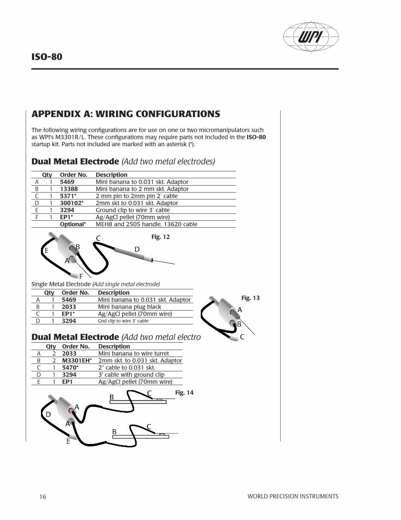
APPENDIX A: WIRING CONFIGURATIONS
The following wiring configurations are for use on one or two micromanipulators such as WPI's M3301R/L. These configurations may require parts not included in the ISO-80 startup kit. Parts not included are marked with an asterisk (*).
Dual Metal Electrode (Add two metal electrodes)Qty Order No. Description
A 1 5469 Mini banana to 0.031 skt. AdaptorB 1 13388 Mini banana to 2 mm skt. AdaptorC 1 5371* 2 mm pin to 2mm pin 2’ cableD 1 300102* 2mm skt to 0.031 skt. AdaptorE 1 3294 Ground clip to wire 3’ cableF 1 EP1* Ag/AgCl pellet (70mm wire)
Optional* MEH8 and 2505 handle, 13620 cable
Single Metal Electrode (Add single metal electrode)Qty Order No. Description
A 1 5469 Mini banana to 0.031 skt. AdaptorB 1 2033 Mini banana plug blackC 1 EP1* Ag/AgCl pellet (70mm wire)D 1 3294 Gnd clip to wire 3’ cable
Dual Metal Electrode (Add two metal electrodes)Qty Order No. Description
A 2 2033 Mini banana to wire turretB 2 M3301EH* 2mm skt. to 0.031 skt. AdaptorC 1 5470* 2” cable to 0.031 skt.D 1 3294 3' cable with ground clipE 1 EP1 Ag/AgCl pellet (70mm wire)
Fig. 12
Fig. 13
Fig. 14

ISO-80
WORLD PRECISION INSTRUMENTS 17
Single Metal Electrode (Add single metal electrode)Qty Order No. Description
A 2 2033 Mini banana plug blackB 1 M3301EH* 2mm skt. to 0.031 skt. AdaptorC 1 5470* 2” cable to 0.031 skt.D 1 EP1* Ag/AgCl pellet (70mm wire)E 1 3294 Ground clip to wire 3’ cable
Dual Micropipette (Add 1 mm glass micropipettes)Qty Order No. Description
A 1 13388 Mini banana to 2 mm skt. AdaptorB 1 5371* 2 mm pin to 2mm pin 2’ cableC 1 300040* 2mm skt to 2mm skt. manipulator holderD 1 MEH1S* 1mm pipette holder (2mm pin)E 1 MEH3SBW* Mini banana pipette holderF 1 3294 Ground clip to wire 3’ cableG 1 EP1* Ag/AgCl pellet (70mm wire)
Optional* MEH8 and 2505 handle, 13620 cable
Single Micropipette (Add 1 mm glass micropipette)Qty Order No. Description
A 1 MEH3SBW* Mini banana pipette holderB 1 2033 Mini banana plug blackC 1 EP1* Ag/AgCl pellet (70mm wire)D 1 3294 Ground clip to wire 3’ cable
NOTE: When ordering MEH1S and MEH3SBW, include the appropriate suffix. For example, MEH1S-10. 10 - 1.0mm glass, 12 - 1.2mm glass, 15 - 1.5mm glass, 20 - 2.0mm glass
Fig. 17
Fig. 16
Fig. 8
Fig. 15

ISO-80
WORLD PRECISION INSTRUMENTS18

ISO-80
WORLD PRECISION INSTRUMENTS 19
ISO-80
WORLD PRECISION INSTRUMENTS20
WARRANTYWPI (World Precision Instruments, Inc.) warrants to the original purchaser that this equipment, including its components and parts, shall be free from defects in material and workmanship for a period of one year* from the date of receipt. WPI’s obligation under this warranty shall be limited to repair or replacement, at WPI’s option, of the equipment or defective components or parts upon receipt thereof f.o.b. WPI, Sarasota, Florida U.S.A. Return of a repaired instrument shall be f.o.b. Sarasota.
The above warranty is contingent upon normal usage and does not cover products which have been modified without WPI’s approval or which have been subjected to unusual physical or electrical stress or on which the original identification marks have been removed or altered. The above warranty will not apply if adjustment, repair or parts replacement is required because of accident, neglect, misuse, failure of electric power, air conditioning, humidity control, or causes other than normal and ordinary usage.
To the extent that any of its equipment is furnished by a manufacturer other than WPI, the foregoing warranty shall be applicable only to the extent of the warranty furnished by such other manufacturer. This warranty will not apply to appearance terms, such as knobs, handles, dials or the like.
WPI makes no warranty of any kind, express or implied or statutory, including without limitation any warranties of merchantability and/or fitness for a particular purpose. WPI shall not be liable for any dam-ages, whether direct, indirect, special or consequential arising from a failure of this product to operate in the manner desired by the user. WPI shall not be liable for any damage to data or property that may be caused directly or indirectly by use of this product.
Claims and Returns• Inspect all shipments upon receipt. Missing cartons or obvious damage to cartons should be noted on the delivery receipt before signing. Concealed loss or damage should be reported at once to the carrier and an inspection requested. All claims for shortage or damage must be made within 10 days after receipt of ship-ment. Claims for lost shipments must be made within 30 days of invoice or other notification of shipment. Please save damaged or pilfered cartons until claim settles. In some instances, photographic documentation may be required. Some items are time sensitive; WPI assumes no extended warranty or any liability for use beyond the date specified on the container.
• WPI cannot be held responsible for items damaged in shipment en route to us. Please enclose merchan-dise in its original shipping container to avoid damage from handling. We recommend that you insure merchandise when shipping. The customer is responsible for paying shipping expenses including adequate insurance on all items returned.
• Do not return any goods to WPI without obtaining prior approval and instructions (RMA#) from our returns department. Goods returned unauthorized or by collect freight may be refused. The RMA# must be clearly displayed on the outside of the box, or the package will not be accepted. Please contact the RMA depart-ment for a request form.
• Goods returned for repair must be reasonably clean and free of hazardous materials.
• A handling fee is charged for goods returned for exchange or credit. This fee may add up to 25% of the sale price depending on the condition of the item. Goods ordered in error are also subject to the handling fee.
• Equipment which was built as a special order cannot be returned.
• Always refer to the RMA# when contacting WPI to obtain a status of your returned item.
• For any other issues regarding a claim or return, please contact the RMA department
Warning: This equipment is not designed or intended for use on humans.
* Electrodes, batteries and other consumable parts are warranted for 30 days only from the date on which the customer receives these items.
World Precision Instruments, Inc.International Trade Center, 175 Sarasota Center Blvd., Sarasota FL 34240-9258
Tel: 941-371-1003 • Fax: 941-377-5428 • E-mail: [email protected]: Astonbury Farm Business Centre • Aston, Stevenage, Hertfordshire SG2 7EG • Tel: 01438-880025 • Fax: 01438-880026 • E-mail: [email protected]
Germany: Liegnitzer Str. 15, D-10999 Berlin • Tel: 030-6188845 • Fax: 030-6188670 • E-mail: [email protected]