iso1685dp d00272 02 m xxen - bender uk ltd. · iso1685dp_d00272_02_m_xxen/07.2017. ......
TRANSCRIPT

EN Manual
Insulation monitoring device for unearthedAC, AC/DC and DC power supplies (IT systems)up to AC 1000 V / DC 1500 VSoftware version D484 V2.xx
D485 V1.xx
ISOMETER® iso1685DP
iso1685DP_D00272_02_M_XXEN/07.2017

Bender GmbH & Co. KGPostfach 1161 • 35301 Gruenberg • GermanyLondorfer Straße 65 • 35305 Gruenberg • Germany
Tel.: +49 6401 807-0Fax: +49 6401 807-259
E-Mail: [email protected]: www.bender.de
© Bender GmbH & Co. KGAll rights reserved.
Reproduction only with permissionof the publisher.
Subject to change.
Customer serviceService-Hotline: 0700-BenderHelp (Telephone and Fax)Carl-Benz-Straße 8 • 35305 Grünberg • Germany
Tel.:+49 6401 807-760Fax:+49 6401 807-629
E-Mail:[email protected]

In
3 iso1685DP_D00272_02_M_XXEN/07.2017
1
2
3
...........................................................................17. . . . . . . . . . . . . . . . . . . . . . . . . . . . . . . . . . . . . . . . . . . . . . . . . . . .17
. . . . . . . . . . . . . . . . . . . . . . . . . . . . . . . . . . . . . . . . . . . . . . . . . . . .18
rating elements . . . . . . . . . . . . . . . . . . . . . . . . . . . . . . . . . . . .19
ents . . . . . . . . . . . . . . . . . . . . . . . . . . . . . . . . . . . . . . . . . . . . . .19
ns . . . . . . . . . . . . . . . . . . . . . . . . . . . . . . . . . . . . . . . . . . . . . . . .19
lements in the service lid . . . . . . . . . . . . . . . . . . . . . . . . . . .19
nnection ..........................................................20. . . . . . . . . . . . . . . . . . . . . . . . . . . . . . . . . . . . . . . . . . . . . . . . . . . .20
. . . . . . . . . . . . . . . . . . . . . . . . . . . . . . . . . . . . . . . . . . . . . . . . . . . .20
requirements . . . . . . . . . . . . . . . . . . . . . . . . . . . . . . . . . . . . . .20
connection of the ISOMETER® . . . . . . . . . . . . . . . . . . . . .21
the EDS to the ISOMETER® . . . . . . . . . . . . . . . . . . . . . . . . .21
n AC system . . . . . . . . . . . . . . . . . . . . . . . . . . . . . . . . . . . . . . .22
mple of the ISOMETER® with an insulation fault locator L) to a 3AC system . . . . . . . . . . . . . . . . . . . . . . . . . . . . . . . . .23
mple of the ISOMETER® with an insulation fault locator n AC system . . . . . . . . . . . . . . . . . . . . . . . . . . . . . . . . . . . . . . .24
...........................................................................25 flow chart insulation fault monitoring . . . . . . . . . . . . . .25
flow chart insulation fault location . . . . . . . . . . . . . . . . .25
ning . . . . . . . . . . . . . . . . . . . . . . . . . . . . . . . . . . . . . . . . . . . . . .26
anguage . . . . . . . . . . . . . . . . . . . . . . . . . . . . . . . . . . . . . . . . . .26
and time . . . . . . . . . . . . . . . . . . . . . . . . . . . . . . . . . . . . . . . . . .26
rofile . . . . . . . . . . . . . . . . . . . . . . . . . . . . . . . . . . . . . . . . . . . . .26
onse value Ran1 for Alarm 1 . . . . . . . . . . . . . . . . . . . . . . .26
onse value Ran2 for Alarm 2 . . . . . . . . . . . . . . . . . . . . . . .27
mode . . . . . . . . . . . . . . . . . . . . . . . . . . . . . . . . . . . . . . . . . . . . .27
current . . . . . . . . . . . . . . . . . . . . . . . . . . . . . . . . . . . . . . . . . . . .27
. . . . . . . . . . . . . . . . . . . . . . . . . . . . . . . . . . . . . . . . . . . . . . . . . . . .27
haltsverzeichnis
. Important information .................................................................... 91.1 How to use this manual . . . . . . . . . . . . . . . . . . . . . . . . . . . . . . . . . . . . . . . . . . . . . 9
1.2 Technical support . . . . . . . . . . . . . . . . . . . . . . . . . . . . . . . . . . . . . . . . . . . . . . . . . . 9
1.2.1 First level support . . . . . . . . . . . . . . . . . . . . . . . . . . . . . . . . . . . . . . . . . . . . . . 9
1.2.2 Repair service . . . . . . . . . . . . . . . . . . . . . . . . . . . . . . . . . . . . . . . . . . . . . . . . . . 9
1.2.3 Field service . . . . . . . . . . . . . . . . . . . . . . . . . . . . . . . . . . . . . . . . . . . . . . . . . . . 10
1.3 Training courses . . . . . . . . . . . . . . . . . . . . . . . . . . . . . . . . . . . . . . . . . . . . . . . . . . . 10
1.4 Delivery conditions . . . . . . . . . . . . . . . . . . . . . . . . . . . . . . . . . . . . . . . . . . . . . . . . 10
1.5 Storage . . . . . . . . . . . . . . . . . . . . . . . . . . . . . . . . . . . . . . . . . . . . . . . . . . . . . . . . . . . 10
1.6 Disposal. . . . . . . . . . . . . . . . . . . . . . . . . . . . . . . . . . . . . . . . . . . . . . . . . . . . . . . . . . . 10
. Safety instructions .......................................................................... 112.1 General safety instructions . . . . . . . . . . . . . . . . . . . . . . . . . . . . . . . . . . . . . . . . . 11
2.2 Work activities on electrical installations. . . . . . . . . . . . . . . . . . . . . . . . . . . . 11
2.3 Device-specific safety information . . . . . . . . . . . . . . . . . . . . . . . . . . . . . . . . . 11
2.4 Address setting and termination . . . . . . . . . . . . . . . . . . . . . . . . . . . . . . . . . . . 12
2.5 Intended use . . . . . . . . . . . . . . . . . . . . . . . . . . . . . . . . . . . . . . . . . . . . . . . . . . . . . . 12
. Function ........................................................................................... 133.1 Features. . . . . . . . . . . . . . . . . . . . . . . . . . . . . . . . . . . . . . . . . . . . . . . . . . . . . . . . . . . 13
3.2 Product description . . . . . . . . . . . . . . . . . . . . . . . . . . . . . . . . . . . . . . . . . . . . . . . 13
3.3 Function description. . . . . . . . . . . . . . . . . . . . . . . . . . . . . . . . . . . . . . . . . . . . . . . 13
3.3.1 Insulation monitoring . . . . . . . . . . . . . . . . . . . . . . . . . . . . . . . . . . . . . . . . . 14
3.3.2 Insulation fault location . . . . . . . . . . . . . . . . . . . . . . . . . . . . . . . . . . . . . . . 14
3.3.3 Assignment of the alarm relays K1, K2, K3 . . . . . . . . . . . . . . . . . . . . . . 14
3.3.4 Deactivating the device . . . . . . . . . . . . . . . . . . . . . . . . . . . . . . . . . . . . . . . 15
3.3.5 Measured value transmission . . . . . . . . . . . . . . . . . . . . . . . . . . . . . . . . . . 15
3.4 History memory . . . . . . . . . . . . . . . . . . . . . . . . . . . . . . . . . . . . . . . . . . . . . . . . . . . 15
3.5 Self test . . . . . . . . . . . . . . . . . . . . . . . . . . . . . . . . . . . . . . . . . . . . . . . . . . . . . . . . . . . 15
3.5.1 Self test after connection to the supply voltage . . . . . . . . . . . . . . . . 15
3.5.2 Automatic self test . . . . . . . . . . . . . . . . . . . . . . . . . . . . . . . . . . . . . . . . . . . . 16
3.5.3 Manual self test . . . . . . . . . . . . . . . . . . . . . . . . . . . . . . . . . . . . . . . . . . . . . . . 16
4. Device overview ...4.1 Dimensions. . . .
4.2 Connections . . .
4.3 Display and ope
4.3.1 Display elem
4.3.2 Device butto
4.3.3 Operating e
5. Installation and co5.1 Installation . . . .
5.2 Connection . . . .
5.2.1 Connection
5.2.2 Step-by-step
5.2.3 Connecting
5.3 Connection to a
5.4 Connection exa(EDS440/441-
5.5 Connection exa(EDS460) to a
6. Commissioning ....6.1 Commissioning
6.2 Commissioning
6.3 Initial commissio
6.3.1 Setting the l
6.3.2 Setting date
6.3.3 Setting the p
6.3.4 Setting resp
6.3.5 Setting resp
6.3.6 Setting EDS
6.3.7 Set the EDS
6.3.8 TEST . . . . . .

T
iso1685DP_D00272_02_M_XXEN/07.20174
7
8
9
9.1 (1.6.1.1) Mode . . . . . . . . . . . . . . . . . . . . . . . . . . . . . . . . . . . . . . . . . . . 34
zzer . . . . . . . . . . . . . . . . . . . . . . . . . . . . . . . . . . . . . . . . . . . . . . 35 TEST. . . . . . . . . . . . . . . . . . . . . . . . . . . . . . . . . . . . . . . . . . . . . 35 Function 1 . . . . . . . . . . . . . . . . . . . . . . . . . . . . . . . . . . . . . . . 36 Function 2 . . . . . . . . . . . . . . . . . . . . . . . . . . . . . . . . . . . . . . . 36sulation fault location) . . . . . . . . . . . . . . . . . . . . . . . . . . . .36. . . . . . . . . . . . . . . . . . . . . . . . . . . . . . . . . . . . . . . . . . . . . . . . . . 36nt . . . . . . . . . . . . . . . . . . . . . . . . . . . . . . . . . . . . . . . . . . . . . . . . 37easured values . . . . . . . . . . . . . . . . . . . . . . . . . . . . . . . . . . .37l . . . . . . . . . . . . . . . . . . . . . . . . . . . . . . . . . . . . . . . . . . . . . . . . . .37 . . . . . . . . . . . . . . . . . . . . . . . . . . . . . . . . . . . . . . . . . . . . . . . . . .37 settings . . . . . . . . . . . . . . . . . . . . . . . . . . . . . . . . . . . . . . . . . .37uage. . . . . . . . . . . . . . . . . . . . . . . . . . . . . . . . . . . . . . . . . . . . . . 38
. . . . . . . . . . . . . . . . . . . . . . . . . . . . . . . . . . . . . . . . . . . . . . . . . . 38me . . . . . . . . . . . . . . . . . . . . . . . . . . . . . . . . . . . . . . . . . . . . . . . 38rmat (time) . . . . . . . . . . . . . . . . . . . . . . . . . . . . . . . . . . . . . . . 38mmer time . . . . . . . . . . . . . . . . . . . . . . . . . . . . . . . . . . . . . . . 38
ate. . . . . . . . . . . . . . . . . . . . . . . . . . . . . . . . . . . . . . . . . . . . . . . . 38rmat (date) . . . . . . . . . . . . . . . . . . . . . . . . . . . . . . . . . . . . . . . 38
face. . . . . . . . . . . . . . . . . . . . . . . . . . . . . . . . . . . . . . . . . . . . . . . 39S . . . . . . . . . . . . . . . . . . . . . . . . . . . . . . . . . . . . . . . . . . . . . . . . 39
BMS address. . . . . . . . . . . . . . . . . . . . . . . . . . . . . . . . . . . . . 39ay . . . . . . . . . . . . . . . . . . . . . . . . . . . . . . . . . . . . . . . . . . . . . . . . 39ightness . . . . . . . . . . . . . . . . . . . . . . . . . . . . . . . . . . . . . . . . . . 39ord . . . . . . . . . . . . . . . . . . . . . . . . . . . . . . . . . . . . . . . . . . . . . . 39ssword . . . . . . . . . . . . . . . . . . . . . . . . . . . . . . . . . . . . . . . . . . . 39atus . . . . . . . . . . . . . . . . . . . . . . . . . . . . . . . . . . . . . . . . . . . . . . 39missioning . . . . . . . . . . . . . . . . . . . . . . . . . . . . . . . . . . . . . . . . 39ce . . . . . . . . . . . . . . . . . . . . . . . . . . . . . . . . . . . . . . . . . . . . . . . . 39. . . . . . . . . . . . . . . . . . . . . . . . . . . . . . . . . . . . . . . . . . . . . . . . . . . .39
. . . . . . . . . . . . . . . . . . . . . . . . . . . . . . . . . . . . . . . . . . . . . . . . . . . .40
9.1 (1.6.1.2) t(on) . . . . . . . . . . . . . . . . . . . . . . . . . . . . . . . . . . . . . . . . . . . . 349.1 (1.6.1.3) t(off) . . . . . . . . . . . . . . . . . . . . . . . . . . . . . . . . . . . . . . . . . . . . 349.1 (1.6.1.4) Function . . . . . . . . . . . . . . . . . . . . . . . . . . . . . . . . . . . . . . . . 35
9.1 (1.6.2) Digital 2 . . . . . . . . . . . . . . . . . . . . . . . . . . . . . . . . . . . . . . . . . . . . 359.1 (1.7) Outputs . . . . . . . . . . . . . . . . . . . . . . . . . . . . . . . . . . . . . . . . . . . . . . . 35
9.1 (1.7.1) Relay 1 . . . . . . . . . . . . . . . . . . . . . . . . . . . . . . . . . . . . . . . . . . . . . 359.1 (1.7.1.1) TEST . . . . . . . . . . . . . . . . . . . . . . . . . . . . . . . . . . . . . . . . . . . . 359.1 (1.7.1.2) Operating mode . . . . . . . . . . . . . . . . . . . . . . . . . . . . . . . . 35
9.1 (1.7.2) Relay 2 . . . . . . . . . . . . . . . . . . . . . . . . . . . . . . . . . . . . . . . . . . . . . 35
Table of contentsable of contents
6.4 Recommissioning . . . . . . . . . . . . . . . . . . . . . . . . . . . . . . . . . . . . . . . . . . . . . . . . . 27
6.5 Commissioning EDS . . . . . . . . . . . . . . . . . . . . . . . . . . . . . . . . . . . . . . . . . . . . . . . 28
. Display .............................................................................................. 297.1 Standard display. . . . . . . . . . . . . . . . . . . . . . . . . . . . . . . . . . . . . . . . . . . . . . . . . . . 29
7.2 Fault indication (active) . . . . . . . . . . . . . . . . . . . . . . . . . . . . . . . . . . . . . . . . . . . . 29
7.3 Fault indication (inactive) . . . . . . . . . . . . . . . . . . . . . . . . . . . . . . . . . . . . . . . . . . 30
7.4 Acknowledging a fault message . . . . . . . . . . . . . . . . . . . . . . . . . . . . . . . . . . . 30
7.5 Data - isoGraph. . . . . . . . . . . . . . . . . . . . . . . . . . . . . . . . . . . . . . . . . . . . . . . . . . . . 31
7.6 History memory . . . . . . . . . . . . . . . . . . . . . . . . . . . . . . . . . . . . . . . . . . . . . . . . . . . 31
7.7 Insulation fault location. . . . . . . . . . . . . . . . . . . . . . . . . . . . . . . . . . . . . . . . . . . . 31
. Menu ................................................................................................. 328.1 Overview of the device menu . . . . . . . . . . . . . . . . . . . . . . . . . . . . . . . . . . . . . . 32
8.2 Operation and Navigation . . . . . . . . . . . . . . . . . . . . . . . . . . . . . . . . . . . . . . . . . 32
. Settings............................................................................................. 339.1 (1.0) Alarm settings. . . . . . . . . . . . . . . . . . . . . . . . . . . . . . . . . . . . . . . . . . 33
9.1 (1.1) Insulation alarm . . . . . . . . . . . . . . . . . . . . . . . . . . . . . . . . . . . . . . . 339.1 (1.1.1) Alarm 1 . . . . . . . . . . . . . . . . . . . . . . . . . . . . . . . . . . . . . . . . . . . . 339.1 (1.1.2) Alarm 2 . . . . . . . . . . . . . . . . . . . . . . . . . . . . . . . . . . . . . . . . . . . . 33
9.1 (1.2) Profile. . . . . . . . . . . . . . . . . . . . . . . . . . . . . . . . . . . . . . . . . . . . . . . . . 339.1 (1.3) Fault memory . . . . . . . . . . . . . . . . . . . . . . . . . . . . . . . . . . . . . . . . . 339.1 (1.4) Device . . . . . . . . . . . . . . . . . . . . . . . . . . . . . . . . . . . . . . . . . . . . . . . . 349.1 (1.5) Coupling monitoring . . . . . . . . . . . . . . . . . . . . . . . . . . . . . . . . . . 349.1 (1.6) Inputs . . . . . . . . . . . . . . . . . . . . . . . . . . . . . . . . . . . . . . . . . . . . . . . . . 34
9.1 (1.6.1) Digital 1 . . . . . . . . . . . . . . . . . . . . . . . . . . . . . . . . . . . . . . . . . . . . 34
9.1 (1.7.3) Bu9.1 (1.7.3.1)9.1 (1.7.3.2)9.1 (1.7.3.3)
9.1 (2.0) EDS (in9.1 (2.1) Mode9.1 (2.2) Curre
9.1 (3.0) Data m9.1 (4.0) Contro9.1 (5.0) History9.1 (6.0) Device
9.1 (6.1) Lang9.1 (6.2) Clock
9.1 (6.2.1) Ti9.1 (6.2.2) Fo9.1 (6.2.3) Su9.1 (6.2.4) D9.1 (6.2.5) Fo
9.1 (6.3) Inter9.1 (6.3.1) BM
9.1 (6.3.1.1)9.1 (6.4) Displ
9.1 (6.4.1) Br9.1 (6.5) Passw
9.1 (6.5.1) Pa9.1 (6.5.2) St
9.1 (6.6) Com9.1 (6.7) Servi
9.1 (7.0) Info .
9.2 Factory settings

T
iso1685DP_D00272_02_M_XXEN/07.20175
1
1
1
1
1
14.2 Response time profile High capacitance. . . . . . . . . . . . . . . . . . . . . . . . . . . 49
...........................................................................54o1685DP . . . . . . . . . . . . . . . . . . . . . . . . . . . . . . . . . . . . . . . . . . .54
certifications. . . . . . . . . . . . . . . . . . . . . . . . . . . . . . . . . . . . . . .55
ls . . . . . . . . . . . . . . . . . . . . . . . . . . . . . . . . . . . . . . . . . . . . . . . . . .55
14.3 Response time profile Inverter > 10 Hz . . . . . . . . . . . . . . . . . . . . . . . . . . . . 50
14.4 Response time profile Inverter < 10 Hz . . . . . . . . . . . . . . . . . . . . . . . . . . . . 51
14.5 Response time profile Fast 2000 μF . . . . . . . . . . . . . . . . . . . . . . . . . . . . . . . 52
14.6 Leakage capacitance . . . . . . . . . . . . . . . . . . . . . . . . . . . . . . . . . . . . . . . . . . . . . 53
Table of contentsable of contents
0. Device communication via the BMS bus .................................. 4110.1 RS-485 interface with BMS protocol . . . . . . . . . . . . . . . . . . . . . . . . . . . . . . . 41
10.2 Topology RS-485 network . . . . . . . . . . . . . . . . . . . . . . . . . . . . . . . . . . . . . . . . 41
10.3 BMS protocol. . . . . . . . . . . . . . . . . . . . . . . . . . . . . . . . . . . . . . . . . . . . . . . . . . . . . 42
10.4 BMS master . . . . . . . . . . . . . . . . . . . . . . . . . . . . . . . . . . . . . . . . . . . . . . . . . . . . . . 42
10.5 Commissioning of an RS-485 network with BMS protocol . . . . . . . . . . 42
10.6 Setting BMS address. . . . . . . . . . . . . . . . . . . . . . . . . . . . . . . . . . . . . . . . . . . . . . 42
10.7 Alarm and operating messages via the BMS bus . . . . . . . . . . . . . . . . . . . 43
10.7.1 Alarm messages . . . . . . . . . . . . . . . . . . . . . . . . . . . . . . . . . . . . . . . . . . . . . . 43
10.7.2 Operating messages . . . . . . . . . . . . . . . . . . . . . . . . . . . . . . . . . . . . . . . . . . 43
10.7.3 Resetting error messages . . . . . . . . . . . . . . . . . . . . . . . . . . . . . . . . . . . . . 43
10.7.4 Error codes . . . . . . . . . . . . . . . . . . . . . . . . . . . . . . . . . . . . . . . . . . . . . . . . . . . 44
1. Insulation fault location .............................................................. 4511.1 General description . . . . . . . . . . . . . . . . . . . . . . . . . . . . . . . . . . . . . . . . . . . . . . 45
11.2 Required settings for insulation fault location . . . . . . . . . . . . . . . . . . . . . 45
11.3 Indication on the display . . . . . . . . . . . . . . . . . . . . . . . . . . . . . . . . . . . . . . . . . 45
11.4 Starting and stopping the insulation fault location . . . . . . . . . . . . . . . . 45
2. Device profiles .............................................................................. 46
3. Alarm messages ............................................................................ 47
4. Diagrams ........................................................................................ 4814.1 Response time profile Power circuits . . . . . . . . . . . . . . . . . . . . . . . . . . . . . . 48
15. Technical data ....15.1 Tabular data is
15.2 Standards and
15.3 Ordering detai

iso1685DP_D00272_02_M_XXEN/07.2017
1
1
AThth
rtbleshooting Bender offers you:
rt or e-mail for all Bender products
pecific customer applications
401 807-760*401 807-259enderHelp (Tel. and Fax)[email protected]
nd replacement service for Bender products
esting and analysing Bender products
update for Bender devices
t devices in the event of faulty or incorrectly delivered
Bender devices, which includes an in-house repair service or no extra cost
401 807-780** (technical issues)401 807-784**, -785** (sales)401 [email protected]
epair to the following address:
r GmbH, Repair-Service,rfer Strasse 65, Grünberg
9
This symbol denotes information intended to assist the user in makingoptimum use of the product.
Please send the devices for r
BendeLondo35305
Important information. Important information
.1 How to use this manual
lways keep this manual within easy reach for future reference.o make it easier for you to understand and revisit certain sections in this manual, we ave used symbols to identify important instructions and information. The meaning of ese symbols is explained below:
This manual is intended for qualified personnel working in electrical en-gineering and electronics!
This signal word indicates that there is a high risk of danger that will re-sult in electrocution or serious injury if not avoided.
This signal word indicates a medium risk of danger that can lead todeath or serious injury if not avoided.
This signal word indicates a low-level risk that can result in minor ormoderate injury or damage to property if not avoided.
DANGER
WARNING
CAUTION
1.2 Technical suppoFor commissioning and trou
1.2.1 First level suppoTechnical support by phone
• Questions concerning s
• Commissioning
• Troubleshooting
Telephone: +49 6Fax: +49 6In Germany only: 0700BE-mail: suppo
1.2.2 Repair serviceRepair, calibration, update a
• Repairing, calibrating, t
• Hardware and software
• Delivery of replacemenBender devices
• Extended guarantee forreplacement devices at
Telephone: +49 6+49 6
Fax: +49 6E-mail: repair

Im
iso1685DP_D00272_02_M_XXEN/07.20171
1O
T
FEIn
*A**
1BTe
1BFTEcedelivery conditions for products and services in the electrical industry) set out by the ZVEI (ZES
1Tspsu
ations and laws governing the disposal of this device. Ask sure how to dispose of the old equipment. trical and electronic equipment (WEEE directive) and the di-certain hazardous substances in electrical and electronic apply in the European Community. In Germany, these poli-gh the "Electrical and Electronic Equipment Act" (ElektroG). ing applies:
equipment are not part of household waste.
tors are not part of household waste and must be disposed e regulations.
onic equipment from users other than private households o the market after 13 August 2005 must be taken back by the sed of properly.
e disposal of Bender devices, refer to our homepage at vice & support.
0
entralverband Elektrotechnik- und Elektronikindustrie e. V.) (German Electrical and lectronic Manufacturer's Association) also applies.ale and delivery conditions can be obtained from Bender in printed or electronic format.
.5 Storagehe devices must only be stored in areas where they are protected from dust, damp, and
ray and dripping water, and in which the specified storage temperatures can be en-red.
Important informationportant information
.2.3 Field servicen-site service for all Bender products
• Commissioning, parameter setting, maintenance, troubleshooting for Bender prod-ucts
• Analysis of the electrical installation in the building (power quality test, EMC test, thermography)
• Training courses for customers
elephone: +49 6401 807-752**, -762 **(technical issues)+49 6401 807-753** (sales)
ax: +49 6401 807-759-mail: [email protected]: www.bender-de.com
vailable from 7.00 a.m. to 8.00 p.m. 365 days a year (CET/UTC+1)Mo-Thu 7.00 a.m. - 8.00 p.m., Fr 7.00 a.m. - 13.00 p.m.
.3 Training coursesender is happy to provide training regarding the use of test equipment. he dates of training courses and workshops can be found on the Internet at www.bend-r-de.com -> Know-how -> Seminars.
.4 Delivery conditionsender sale and delivery conditions apply. or software products the "Softwareklausel zur Überlassung von Standard-Software als eil von Lieferungen, Ergänzung und Änderung der Allgemeinen Lieferbedingungen für rzeugnisse und Leistungen der Elektroindustrie" (software clause in respect of the li-
nsing of standard software as part of deliveries, modifications and changes to general
1.6 DisposalAbide by the national regulyour supplier if you are not The directive on waste elecrective on the restriction of equipment (RoHS directive)cies are implemented throuAccording to this, the follow
• Electrical and electronic
• Batteries and accumulaof in accordance with th
• Old electrical and electrwhich was introduced tmanufacturer and dispo
For more information on thwww.bender-de.com -> Ser

iso1685DP_D00272_02_M_XXEN/07.2017
2
2Pst
2
Ifau
2
voltage!
ctric shock!ning the device, you may come into contact with live parts.the mains voltage before opening the device!
that the basic settings meet the requirements of the IT system.ithout the required expertise, in particular children, must nots to or contact with the ISOMETER®.
that the operating voltage is correct!ulation and voltage tests, the ISOMETER® must be disconnected system for the duration of the test. In order to check the correct of the device, a functional test has to be carried out before start-em.
t of an alarm message of the ISOMETER®, the insulation faultliminated as quickly as possible.
ETER® is installed inside a control cabinet, the insulation faultust be audible and/or visible to attract attention.
g ISOMETER®s in IT systems, make sure that only one active ISO-onnected in each interconnected system. If IT systems are in-d via coupling switches, make sure that ISOMETER®s not
sed are disconnected from the IT system and deactivated. ITupled via diodes or capacitances may also influence the insu-itoring process so that a central control of the different ISOME-uired.
11
An excessive locating current of the internal locating current injector maydamage sensitive loads (e.g. control circuits) or trigger unwanted switch-ing operations. Select a low locating current for these systems. In case ofdoubt, please contact our service department.
DANGER
METER® is cterconnectecurrently usystems colation monTER®s is req
Safety instructions. Safety instructions
.1 General safety instructionsart of the device documentation in addition to this manual is the enclosed "Safety in-ructions for Bender products".
.2 Work activities on electrical installations.
the device is used outside the Federal Republic of Germany, the applicable local stand-rds and regulations must be complied with. The European standard EN 50110 can be sed as a guide.
.3 Device-specific safety information
Only qualified personnel are permitted to carry out the work necessaryto install, commission and run a device or system.
Risk of electrocution due to electric shock!Touching live parts of the system carries the risk of: • An electric shock • Damage to the electrical installation • Destruction of the deviceBefore installing and connecting the device, make sure that the in-stallation has been de-energised. Observe the rules for working on elec-trical installations.
Danger as a result of excessive locating current or excessive locating
DANGER
Risk of eleWhen opeSwitch off
Make surePersons whave acces
Make surePrior to insfrom the ITconnectioning the syst
In the evenshould be e
If the ISOMmessage m
When usin
DANGER
WARNING
CAUTION

S
iso1685DP_D00272_02_M_XXEN/07.20171
2Cis
E
oring the insulation resistance in large power supply systems specific measurement technique (AMP+) monitors the insu-allations where extremely high system leakage capacitances ence suppression methods. The adjustment also to high sys-ccurs automatically.ng current pulses required for insulation fault location. That e insulation fault using permanently installed or mobile insu-
formation in the operating manual
tervals
ments of applicable standards, the equipment must be ad-nd operating conditions by means of customised parameter its of the range of application indicated in the technical data.
cribed in this manual is regarded as improper.
fied personnel are permitted to carry out the work necessaryommission and run a device or system.
2
Safety instructionsafety instructions
.4 Address setting and terminationorrect address setting and termination is essential for proper functioning of the o1685… series insulation monitoring device.
nsure correct address setting and termination of the device!
Prevent measurement errors!When a monitored IT system contains galvanically coupled DC circuits, aninsulation fault can only be detected correctly if the rectifier valves (e.g.rectifier diode, thyristors, IGBTs, frequency inverters, …) carry a minimumcurrent of > 10 mA.
Unspecified frequency rangeWhen connecting to an IT system with frequency components below thespecified frequency range, the response times and response values maydiffer from the indicated technical data. However, depending on the ap-plication and the selected measurement method, continuous insulationmonitoring is also possible in this frequency range.There is no influence on the insulation monitoring for IT systems with fre-quency components above the specified frequency range, e.g. within therange of typical switching frequencies of frequency inverters (2…20 kHz).
Risk of bus errors!Double assignment of addresses on the respective BMS busses can causeserious malfunctions.CAUTION
2.5 Intended use
The device is used for monitdesigned as IT systems. Thelation resistance also in instto earth exist due to interfertem leakage capacitances oThe device generates locatiallows the localisation of thlation fault locators.
Intended use also implies:
• The observation of all in
• Compliance with test in
In order to meet the requirejusted to local equipment asettings. Please heed the lim
Any other use than that des
Only qualito install, c

iso1685DP_D00272_02_M_XXEN/07.2017
3
3
3T6
ptionevice ISOMETER® iso1685DP-425 continuously monitors the
of an IT system during operation and triggers an alarm when t response value. To obtain a measurement, the device has e IT system (unearthed system) and the protective earth con-
rrent in the μA range is superimposed onto the system which y a microcontrolled measuring circuit. The measuring time asurement methods, the system leakage capacitance, the in-
sible system-related disturbances. In addition, it features an injector for insulation fault location.
her parameters are set using a commissioning wizard or via the device buttons and a high-resolution graphic LC display. red in a permanent fail-safe memory. Different languages
p menus and the messages indicated on the display.
r storing fault messages and events in a history memory with ttings can be protected against unauthorised modifications
over the master function. If there is no master in the system, up master and communicate with the slaves in the system.
13
Function. Function
.1 Features • Insulation monitoring in extensive unearthed power supply systems up to
AC 1000 V/DC 1500 V
• Measurement of low-resistance insulation faults
• Separately adjustable response values Ran1 (alarm 1) and Ran2 (alarm 2) (both 200 Ω…1 MΩ)
• Automatic adjustment to high system leakage capacitances up to 2000 μF, selectable range
• Integrated locating current injector up to 50 mA
• Device self test with automatic message in the event of a fault
• Alarm relays separately adjustable for insulation fault 1, insulation fault 2 and device error
• RS-485 interface (BMS bus), e.g. to control the insulation fault location.
• The device does not have a master function. It can only act as backup master.
• The integrated μSD card slot cannot be used. The device does not store any data on the μSD card.
.2 Product descriptionhe ISOMETER® is an insulation monitoring device for IT systems in accordance with IEC 1557-8 and IEC 61557-9. It is applicable for use in AC/DC systems.
3.3 Function descriThe insulation monitoring dentire insulation resistance the value falls below a preseto be connected between thductor (PE). A measuring cuis recorded and evaluated bdepends on the selected mesulation resistance and posintegrated locating current
The response values and otdifferent setup menus usingThe selected settings are stocan be selected for the setu
The device utilises a clock fotime and date stamp. The seby a password.
The ISOMETER® cannot takethe device can act as a back

F
iso1685DP_D00272_02_M_XXEN/07.20171
3Fsythe
Asuareo
3FITfa
A
ed, the ISOMETER® starts the insulation fault location after the esponse values Ran1 and Ran2. When starting the insulation on" signals the locating current pulse.
insulation fault locators (with master capability) such as used, control and synchronisation of the locating current in-MS master. For this purpose, the ISOMETER® and the insula-
mmunicate with the insulation fault locator via the BMS bus.
sulation fault location ay, e.g. the COM460IP or the terminal program, different he BMS bus:
lt location
tion fault location and pause, alternately 5 minutes each. device automatically switches to insulation fault measure-
uired for insulation fault location is permanently supplied to
locating current required for insulation fault location can be
e alarm relays K1, K2, K3 falls below the alarm response value Ran1
falls below the alarm response value Ran2
a device error or a connection fault.
insulation fault location process, the function of insulation re-easurement is deactivated and the coupling is disconnectedains.
4
bb. 3.2: Pulse sequence of the internal locating current injector for insulation fault location
2 s 4 s 2 s 4 s t 3.3.3 Assignment of thK1 switches when the value(insulation resistance).K2 switches when the value(insulation resistance).K3 switches in the event of
Functionunction
.3.1 Insulation monitoringor insulation monitoring, a pulsating AC measuring voltage is superimposed onto the IT stem. The measuring pulse consists of positive and negative rectangular impulses of e same amplitude. The period duration depends on the system leakage capacitances in
ach case and the insulation resistances of the system to be monitored.
Abb. 3.1: Pulse sequence of the measuring voltage for insulation fault monitoring
n insulation fault between the IT system and earth closes the measuring circuit. If the in-lation resistance between system and earth falls below the set response values Ran1
nd Ran2 (response value Ran1 can be set equal or higher than Ran2), the associated alarm lays K1 (11, 12, 14) or K2 (21, 22, 24) switch. Detected insulation faults are signalled to
ther bus devices via the BMS bus. In addition, the alarm LEDs Alarm 1 or Alarm 2 light up.
.3.2 Insulation fault locationor insulation fault location, a suitable locating current is superimposed onto the faulty system with which insulation fault locators of the EDS… series can locate insulation ults. The ISOMETER® utilises an internal locating current injector with IL ≤ 50 mA DC.
Um
t
IL
If the EDS function is activatvalue has fallen below the rfault location, the LED "PGH
When permanently installedEDS460-D or EDS490-D are jector is carried out via the Btion fault locator have to co
Parameterisation of the inBy means of the BMS gatewmodes can be selected via t
• off:Switch off insulation fau
• auto (automatic):Factory setting = InsulaDuring each pause, thement
• on (permanent):The locating current reqthe device
In addition, the value of theset to 1…50 mA via BMS.
During thesistance mfrom the m

F
iso1685DP_D00272_02_M_XXEN/07.20171
3WfrTpTis
A
Tteto
3AB
3Aaom
nnection to the supply voltageply voltage, all internal measurement functions, the compo-l such as data and parameter memory as well as the connec-he self test is completed after approx. 60 s. Afterwards, the begins.
tion fault is detected, the corresponding alarm will be indicat-ia the alarm relay K3 (31-32-34). This relay continuously oper-de-energises even in case of a complete device failure.he device is being started, the alarm relays are not switched.
as been run and the result was positive.
as been run and the result was negative.
running.
asurement
stem
upling
libration
55 %
5
Functionunction
.3.4 Deactivating the devicehen the device is deactivated, the coupling unit of the device is galvanically isolated
om the system being monitored. he device does not measure the insulation resistance, the message Device inactive ap-ears on the display. The IT system is NOT being monitored!he device uncouples itself from the system to be monitored through an internal system olating switch.
ctivation or deactivation is done via
• a digital input
• the menu item Alarm settings
• the BMS bus
he standby mode of the ISOMETER®, for example, enables application in coupled sys-ms, since in interconnected systems only one insulation monitoring device is allowed be connected in each system.
.3.5 Measured value transmissionll recorded measured values, operating messages and alarms are made available via the MS bus.
.4 History memoryll warnings, alarms and device errors are stored in the internal history memory with date nd time stamp. The time the event started, the time of acknowledgement and the end f the event are recorded. The history memory can be called up and reset via the device enu (see "History" on page 37).
3.5 Self test
3.5.1 Self test after coOnce connected to the supnents of the process controtions to earth are checked. Tnormal measurement modeIf a device error or a conneced in the display as well as vates in N/C operation, i.e. it During this self test, when t
The test h
The test h
The test is
TEST
√ Me
√ Sy
Co
Ca
√

F
iso1685DP_D00272_02_M_XXEN/07.20171
3Ari
ADsw
3TT
D
6
Functionunction
.5.2 Automatic self testll supply voltages are continuously monitored. The following tests are continuously car-ed out in the background:
• Connection E-KE
• Temperature monitoring of coupling and locating current injector
self test is automatically run at 24-hour intervals.uring the automatic self test, the alarm relays K1 (11-12-14) and K2 (21-22-24) are not
itched. K3 won't be switched either.
.5.3 Manual self testhe self test is started via the Test button of the ISOMETER®.he following tests are only carried out in the manual self test mode:
• Internal Flash
• CPU register
• Watchdogs
• Oscillator
• Restart of the device including re-initialisation and recalibration
• Connection monitoring system
uring the manual self test, all alarm relays are switched.

iso1685DP_D00272_02_M_XXEN/07.2017
8,75
mm
5,2 mm
61,8
mm
76,6
mm
39,8 mm
55,7 mm
17
4. Device overview
4.1 Dimensions
ISOMETER®iso1685
PGH ON
246
mm
125
mm
40,5
mm
40,75 mm
51 mm
368 mm
383 mm
401,5 mm
106 mm64
mm

D
iso1685DP_D00272_02_M_XXEN/07.20171
4
KE
KE
A1 A2
A1 A2
t for tion
E, KESeparate connection of E (earth) and KE (reference) to PE.Connect both to PE
A1, A2Supply voltage Us DC 24 VArbitrary polarityConnection via fuses, 6 A each
m
evice overview
8
.2 Connections
I2+ I2- I1+ I1-
I2+ I2- I1+ I1-
CAN 1 CAN 2 RS-485Term.
off on A B S
A B S
k l kT IT
k I kT IT
31 32 34
K3
31 32 34
21 22 24
K2
21 22 24
11 12 14
K1
11 12 14
E
E
I2+I2–I1+I1–Digital inputs
RS-485 Term.offon
CAN 1CAN 2No function
A, B, SRS-485 busconnection (A,B) protocol: BMS S= PE potentialConnect one end of shield
KIkTITNo function
31, 32, 34Relay output for internal device errors (SERVICE LED)
21, 22, 24Relay output for alarm insulation fault
11, 12, 14Relay outpualarm insulafault
L2/L-
L2/-
L1/L+
L1/+
Coupling terminal L2/–.Connection to L2/– of the IT system via 1 A fuse
Coupling terminal L1/+.Connection to L1/+ of the IT systevia 1 A fuses

D
iso1685DP_D00272_02_M_XXEN/07.20171
4
4
1
2
3
4
5
6
ettings in the respective menu using the menu buttons. De-, one of the options displayed below is assigned to the but-
nts in the service lid
e device menu.
he current process or s one step back in the device menu.
e EDS menu.
s up in a list or increases a value.
device self test.
s forwards (e.g. to the next setting step) or parameter.
arms.
s backwards (e.g. to the previous setting step) or parameter.
formation.
an action or a selection.
data and values.
s down in a list or reduces a value.
Operating elements
Function
DIP switch(SS8103)
No function
Button(ST6101)
Alarm reset
Memory card(SD Card)
No function
9
Flashes: Connection fault, check earth and system (L1/+, L2/–)
ALARM 2(yellow)
Insulation fault 2 (alarm):The "ALARM 2" LED lights continuously when the insulation resistance falls below the response value 2, RF < Ran2
Flashes: Connection fault, check earth and system (L1/+, L2/–)
Device overviewevice overview
.3 Display and operating elements
.3.1 Display elements
ON(green)
The operation indicator lights continuously.
The device display shows information regarding the device and the measurements. Further information is available in the chapter “Display” ab Seite 29.
PGH ON(yellow)
The LED "PGH ON" flashes during insulation fault location. It indicates that the locating current for the insulation fault location is generated.
SERVICE(yellow)
When a device error is detected, the SERVICE LED lights.If the LED stays lit, please check the error code list on Seite 41.
ALARM 1(yellow)
Insulation fault 1 (prewarning):The "ALARM 1" LED lights continuously when the insulation resistance falls below the response value 1, RF < Ran1
PGH ON
1
2
3
4
5
4.3.2 Device buttonsYou can adjust the device spending on the menu entrytons.
4.3.3 Operating eleme
7
MENU Opens th
ESCCancels tnavigate
8EDS Opens th
Navigate
9
TEST Starts the
Navigateselects a
10
RESET Resets al
Navigateselects a
11INFO Shows in
OK Confirms
12DATA Indicates
Navigate

iso1685DP_D00272_02_M_XXEN/07.2017
5
5Indinis
5
5
WARNING
word indicates a low-level risk that can result in minor or injury or damage to property if not avoided.
connection from the IT system!lation or voltage tests are to be carried out, the device must bem the system for the test period. Otherwise the device may be
per connection!missioning of the installation, check that the device has been
nnected and check the device functions. Perform a functionaln earth fault via a suitable resistance.
ls are pluggable push-wire terminals. Solid connecting wiresctly plugged in. For connection of flexible cables, the push-wire
ust be pushed open by pressing the corresponding orange in-mechanism with a flat-head screwdriver.
20
Risk of property damage due to unprofessional installation!If more than one insulation monitoring device is connected to a conduc-tively connected system, the system can be damaged. If several devicesare connected, the device does not function and does not signal insula-tion faults. Make sure that only one insulation monitoring device is con-nected in each conductively connected system.
CAUTION
Installation and connection. Installation and connection
.1 Installationstall the device using four M5 screws, refer also to the dimension diagram where the
rilling holes are illustrated (see "Dimensions" on page 17). Install the device so that it is a vertical position with the system coupling (L1/+, L2/–) positioned at the top when it being operated.
.2 Connection
.2.1 Connection requirements
Only qualified personnel are permitted to carry out the work necessaryto install, commission and run a device or system.
Risk of electrocution due to electric shock!Touching live parts of the system carries the risk of: • An electric shock • Damage to the electrical installation • Destruction of the deviceBefore installing and connecting the device, make sure that the in-stallation has been de-energised. Observe the rules for working on elec-trical installations.
Risk of injury from sharp-edged terminals!Risk of lacerations. Touch the enclosure and the terminals with due care.
DANGER
This signalmoderate
Ensure disWhen insuisolated frodamaged.
Check proPrior to comproperly cotest using a
All terminacan be direterminals mterlocking
CAUTION

In
iso1685DP_D00272_02_M_XXEN/07.20172
5C
P
1
2
3
4
5
6
7
DS to the ISOMETER®
lfunctions due to excessive locating current on sensitiverts!g current flowing between the IT system and earth can causeaults in sensitive parts of the system, such as the PLC or relay.t the level of the locating current is compatible with the systemtored.
orrect measuremented locating current may influence other connected insulationion systems. If they measure the injected locating current, theent might be incorrect.
monitoring is deactivated sulation fault location is active.
1
Installation and connectionstallation and connection
.2.2 Step-by-step connection of the ISOMETER®onnect the device according to the wiring diagram.
roceed as follows:
. Connect terminal E and KE to earth (PE)
. Connect terminal A and B to the BMS bus
. Connect terminal S to the bus conductor shield (only at one end of the conductor)
. Connect terminal L1/+ to L1 of the system to be monitored
. Connect terminal L2/– to L2 of the system to be monitored
. Connect terminal A1/A2 to the supply voltage Us
. Connect alarm outputs 11/12/14, 21/22/24 and 31/32/34.
The coupling terminals L1/+ and L2/– are locked. To unplug the terminals,the orange sliders must be slid towards the front (towards the device) tounlock the terminal. Now the terminal can be unplugged.
5.2.3 Connecting the E
Risk of masystem paThe locatincontroller fEnsure thato be moni
Risk of incThe supplifault locatmeasurem
Insulation while the in
In
iso1685DP_D00272_02_M_XXEN/07.20172
5L1/+
L2/-
US
6A6A
PE
A1 A2
stallation and connection
2
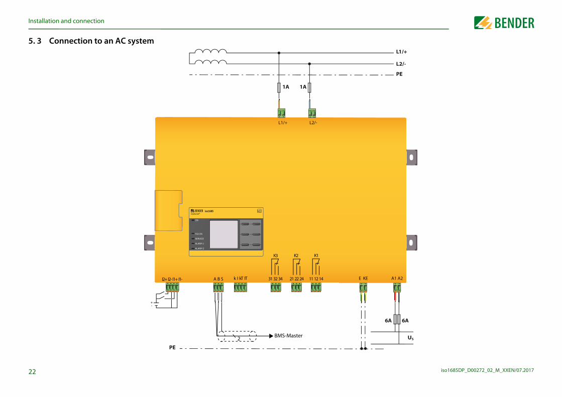
. 3 Connection to an AC system
ISOMETER®iso1685
31 32 34 11 12 1421 22 24
+-
1A1A
BMS-Master2
PE
k I kT ITI2+ I2- I1+ I1- E KE
L2/-L1/+
A B S
K1K3 K2
PGH ON
In
iso1685DP_D00272_02_M_XXEN/07.20172
5 ) to a 3AC system
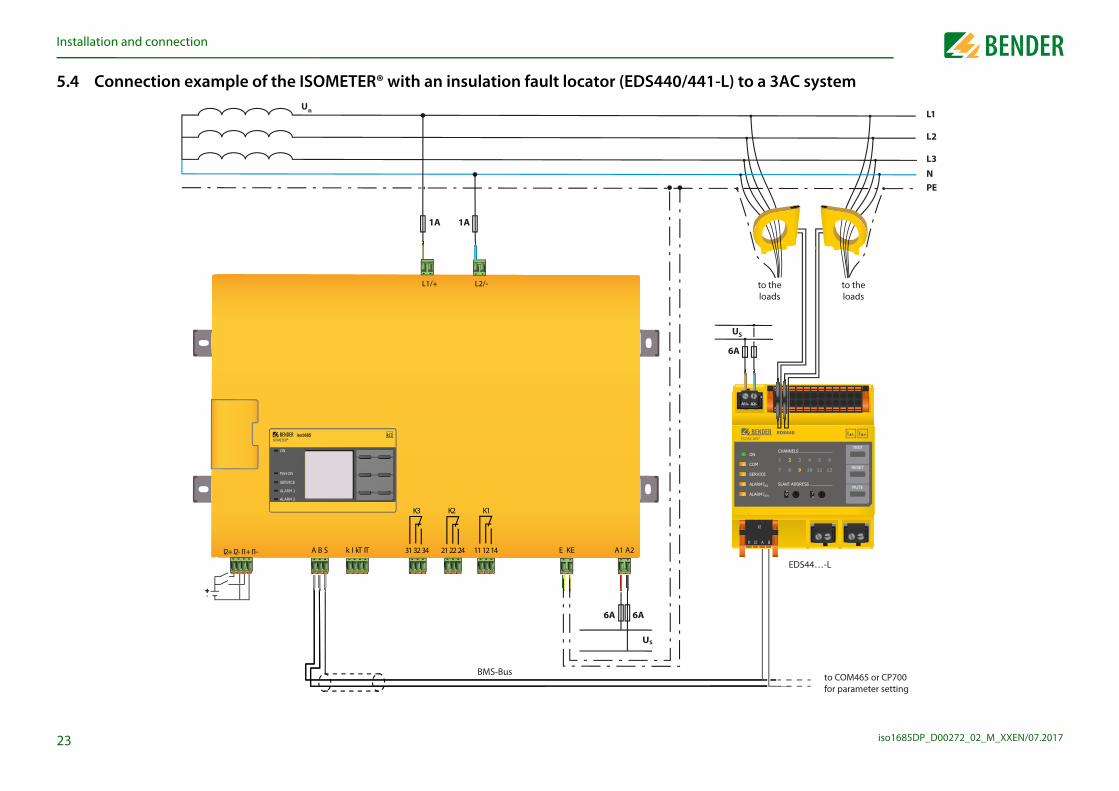
EDS44…-L
ISOSCAN®EDS440 I L
7 6 5
3
8
4
2
01
6
5
34 201
9
8
EDS440ISOSCAN®
TEST
MUTE
RESET
ALARM
ALARM
ON
COM
SERVICE
CHANNELS
SLAVE ADDRESS
121110987
1 2 3 4 5 6
9 7
l l
A1/+ A2/-
I L I n
I∆L
I∆n
to the loads
to the loads
L1
L2
L3
NPE
US
A
to COM465 or CP700 for parameter setting
stallation and connection
3
.4 Connection example of the ISOMETER® with an insulation fault locator (EDS440/441-L
BMS-Bus
++-
Un
6
ISOMETER®iso1685
US
6A6A
1A1A
k I kT ITI2+ I2- I1+ I1- A1 A2E KE
L2/-L1/+
A B S
PGH ON
K1K3 K2
31 32 34 11 12 1421 22 24
In
iso1685DP_D00272_02_M_XXEN/07.20172
5 AC system
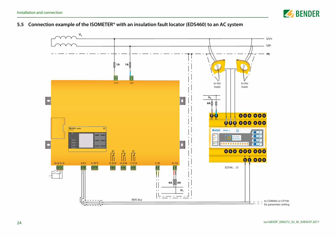
EDS46…-D
es
to the loads
L1/+
L2/-
PE
to COM465 or CP700 for parameter setting
SET
EDS46…L
SLAVE ADDRESS
( ERROR CODE)
TEST
RESET
1 2 3 4 5 6 7 8 9 10 11 12
ESCI s
MONITOR
A B
k1 I k2
stallation and connection
4
.5 Connection example of the ISOMETER® with an insulation fault locator (EDS460) to an
BMS-Bus
to thload
US
Un
6A
ISOMETER®iso1685
US
6A6A
1A1A
k I kT ITI2+ I2- I1+ I1- A1 A2E KE
L2/-L1/+
A B S 31 32 34 11 12 1421 22 24
2
1
ALARM
ON
A1 A2
PGH ON
K1K3 K2
+-

iso1685DP_D00272_02_M_XXEN/07.2017
6
6
yes
flow chart insulation fault location
insulation fault locator e appropriate CTs
the RS-485 interface s) of the EDS with the iso1685DP
Make sure that the system isdisconnected from any electrical
source before connecting the device!
ll BMS components. ss 1 for the 1685DP
(Master)
ct supply voltage
ct system voltage
5DP successfullys out a self test
n test with a suitable between system and
e: 50% of the responsevalue Ran2
LEDs activated? relays switched?
yes
no Set the EDS mode of the iso1685DPto „auto“ via the BMS bus or the display
test button of the EDS
ulty subcircuit beingnised correctly?
yes
l other connectedCTs be tested?
s recognised correctly by the EDS no Check the CT wiring
yes
no
yes Remove the resistance and selectanother location downstream a
measuring transformer where theinsulation fault is to be simulated.
on" of the iso1685DPing. Insulation faulttion is activated
e factory setting beretained?
yes
no Change the settings in the EDS device menu, change the EDS parameters of the
iso1685DP
yes
no Connection or device error:check connections
yes
ve the resistor
Ds extinguished?elays switched?
alarm messages:t button at the EDS or the EDS reset ine EDS menu
no
no
operates properlyonnected correctly
25
Remove resistance
The iso1685DP is correctlyconnected and functions reliably
Alarm LEDs extinguished?Alarm relays switched?
noRemo
Alarm LEAlarm r
Delete Press rese
call upth
The EDSand is c
Commissioning. Commissioning
. 1 Commissioning flow chart insulation fault monitoring
System = IT system ?
Device connection(see chapter Connection)
Un < AC1000 / DC1500 V ?
iso1685DP not suitableno
Deenergize the installation beforeconnecting the device
Connect supply voltage
Connect system voltage
no
yes
yes
iso1685DP not suitable
Connection or device error:Check connections
Use the commissioning wizard to set the device parameters
(see chapter initial commissioning)
Alarm LEDS activated?
no
yes Preset response valueundershot, possibly adjust
Function test with a suitableresistance between system and
earth. Value: 50% of the responsevalue Ran2
Alarm LEDs activated?Alarm relays switched? no Check connections
The iso1685DP successfullycarries out a self test
yes
no
6. 2 Commissioning
Install theand th
Connect(BMS bu
Adress aSet adre
Conne
Conne
iso168carrie
Functioresistance
earth. Valu
AlarmAlarm
Press the
Is the farecog
Shal
Are all CT
LED "PGHis flash
loca
Shall th

C
iso1685DP_D00272_02_M_XXEN/07.20172
6FUre
6T
6Ao
l
lethe insulation monitoring device to the system to be moni-hat suits your system. For an overview of the profiles, refer to 6. The profile Power circuits is suitable for most IT systems.
value Ran1 for Alarm 1 response value here.
se value range changes depending on the selected profile. Re-onse values for insulation monitoring” auf Seite 54.
Profile 6.6.5
• Power circuitso Control circuitso Inverter>10 Hzo Inverter<10 Hz
o Fast 2000 μF
Alarm 1 6.6.6
40 kΩ
min. 200Ωmax. 1MΩ
6
Commissioningommissioning
.3 Initial commissioningollow the instructions of the commissioning wizard on the display.se the device buttons to navigate. For a description of the device buttons, fer to “Device buttons” auf Seite 19.
.3.1 Setting the languagehe language selected here will be used in the menu and for device messages.
.3.2 Setting date and timelarm messages in the history memory and the insulation resistance value over time can nly be assigned correctly to the isoGraph when date and time are set correctly.
Language 6.6.2
• Deutscho English
o ...
Date 6.6.3
14.08.2016
min. 1max. 31
le Commissioning 6.6
Please set the
current date
and time.
2/9
6.3.3 Setting the profiIn order to optimally adapt tored, select a profile here t“Device profiles” auf Seite 4
6.3.4 Setting responseYou can set the prewarning
The responfer to “Resp
lle Commissioning 6.6
Please select a
profile that
suits your
application.
4/9
lle Commissioning 6.6
Please set the
response value
for R(an1) for
Alarm1.
5/9
C
iso1685DP_D00272_02_M_XXEN/07.20172
6TA
6Sin
6SEEF
l
l
l
ion fault location to manual, automatic or 1 cycle. For further ” auf Seite 36.
ngn put into operation before, the self test will be started short-as been connected. You can restart the commissioning wiz-u path:
missioning
odify previously made settings.
issioned before, the self test is not run again. It can be called refer to Seite 37).
evice status!l commissioning has been completed and the initial measure-, the device changes from the alarm state to normal state by
o the set response values.
7
Mode
o off
o manually
• auto
o 1cycle
6.6.8le Commissioning 6.6
Please set the
required EDS
current.
8/9
Commissioningommissioning
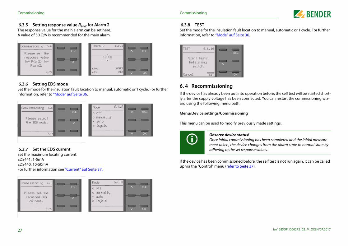
.3.5 Setting response value Ran2 for Alarm 2he response value for the main alarm can be set here. value of 50 Ω/V is recommended for the main alarm.
.3.6 Setting EDS modeet the mode for the insulation fault location to manual, automatic or 1 cycle. For further formation, refer to “Mode” auf Seite 36.
.3.7 Set the EDS currentet the maximum locating current. DS441: 1-5mADS440: 10-50mA or further information see “Current” auf Seite 37.
Alarm 2 6.6.7
10 kΩ
min.max.
200Ω1MΩ
le 6.6
6/9
Commissioning
Please set the
response value
for R(an2) for
Alarm2.
Mode
o off
o manually
• auto
o 1cycle
6.6.8le Commissioning 6.6
Please select
the EDS mode.
7/9
6.3.8 TESTSet the mode for the insulatinformation, refer to “Mode
6. 4 RecommissioniIf the device has already beely after the supply voltage hard using the following men
Menu/Device settings/Com
This menu can be used to m
If the device has been commup via the "Control" menu (
Observe dOnce initiament takenadhering t
lle TEST 6.6.10
Start Test?
Relais may
switch.
Cancel TEST

C
iso1685DP_D00272_02_M_XXEN/07.20172
6P
1
2
Inis
l
l
8
Commissioningommissioning
.5 Commissioning EDSroceed as follows to put into operation an EDS after commissioning the ISOMETER®:
. Set the mode for the insulation fault location to manual, automatic or 1 cycle. For a description of the different modes, refer to “Mode” auf Seite 36.
. Test if the maximum locating current to the EDS is correct and adjust if necessary (refer to 6.3.7 “Set the EDS current” auf Seite 27).Menu path: Menu/EDS/Current
addition to this chapter, commissioning of the ISOMETER® in combination with an EDS described in the “Commissioning flow chart insulation fault location” auf Seite 25.
le
Mode
o off
o manually
• auto
o 1cycle
6.6.8
le Current 6.6.9
o 1mA
o 1.5mA
o 2.5mA
o 3mA
o 10mA

iso1685DP_D00272_02_M_XXEN/07.2017
7
7Dre
Inp
(active)y The upper part of the display becomes orange and
ault, the LEDs ALARM 1, ALARM 2 or SERVICE are activated.
nsulation resistance is still 7 kΩ. Since the values Ran1=40 kΩ low the set response value, ALARM 1 and ALARM 2 have been
e appeared, you can navigate through the faults using the
n a DC system or a DC offset is detected in an AC system, ad- regarding the DC offset will be displayed as illustrated
7 kΩ
sulation fault
7 kΩ
1/4
29
If the value falls below Ran1 iditional detailed informationabove.
Display. Display
.1 Standard displayuring normal operation, the ISOMETER® displays the message OK and below, the cur-ntly measured insulation resistance.
the bottom line of the display, the set limit values for R(an) are indicated. In the exam-le below, Ran1=40 kΩ and Ran2=10 kΩ.
The signal quality of the measurement suits the selected profile.The better the signal quality, the faster and more exact the device can measure.
The signal quality of the measurement does not suit the selected pro-file. Select a different measurement method.
Update period between the test pulses
IT system
OK 230 kΩ
R(an) 40kΩ/10kΩ
OK 230 kΩ
EDS off
PGH ON
7.2 Fault indicationAn active fault is displayed bdisplays the fault message.
Depending on the type of f
In the example below, the iand Ran2=10 kΩ are both betriggered.
If several fault messages havand buttons.
In
PGH ON

D
iso1685DP_D00272_02_M_XXEN/07.20173
7Aw
Tb
Ifaw
PGH ON
a fault messagee fault message and return to the ISOMETER®'s standard dis-owledged by means of the reset button.
ges can only be reset when the cause of fault has been elim-
and OK to clear the fault memory. The ISOMETER® then re-y.
RESET 3.2
Reset current
messages? All
messages are
saved in the
history memory.
Cancel RESET
0
28.08.16 17:02
28.08.16 17:18
2/4
Displayisplay
.3 Fault indication (inactive)n inactive fault is displayed by . If several faults have occurred, the number of faults ill also be indicated.
he message shown on the display below means that there has been a fault in the past ut the device is no longer in fault condition.
several fault messages have appeared, you can navigate through the faults using the nd button. In addition to the type of fault and the associated alarm value, you can see hen the fault has occurred and for how long it has been active.
230 kΩ
IT system
3x
1/4
230 kΩ
EDS off
PGH ON
7 kΩ
Insulation fault
7 kΩ
7.4 AcknowledgingIn order to acknowledge thplay, all faults must be ackn
This means that fault messainated.
Press the reset button, thenturns to the standard displa
PGH ON

D
iso1685DP_D00272_02_M_XXEN/07.20173
7TtiTdTMjee1g
7Uaw
Leave view
locationated, the ISOMETER® indicates the message "Ins. fault locat.". S mode is activated. On the right side it indicates the polarity lses including the pause in between.
y . The upper part of the display becomes orange and The alarm LEDs are lit. If several fault messages have ap-rough the faults using the and buttons.
rding the different modes, refer to “Mode” auf Seite 36
ing pulse rising edge
ing pulse falling edge
ulation fault location function has been deactivated
ulation fault location is in "auto" modegram below)
ulation fault location is in "1 cycle" mode
ulation fault location is in "manual" mode
IT-System
1x
1/2
1x
ault locationault location
S auto
PGH ON
1
Insulation fault
11kΩ
28.03.14 17:02
28.03.14 17:18
8/8
Number of selected erroTotal number of error messages
Previous message
Fault descriptionAlarm value
Fault occuredFault disappeared
PGH ON
For further information rega
FF
ED
Displayisplay
. 5 Data - isoGraphhe isoGraph represents the chronological sequence of the insulation resistance over me. his graphical representation can be displayed over the following time periods: hour, ay, week, month and year. he measured values for individual representations are stored in a separate memory. easured values for insulation, voltage, PGH current (current of the locating current in-ctor) and the temperature of the coupling and the locating current injector are indicat-
d. You can switch the indication of the different measured values by pressing . Up to 00 measured values are available to represent each graph and the resolution of each raph is determined by these values.
. 6 History memoryp to 1023 alarm messages and device errors are stored in the history memory with date nd time stamp. If the history memory is deleted, the minimum insulation resistance Rmin ill also be reset at Menu/Data Measured values - Data insulation.
1,0,100,010,001 MΩHour 16:26 16:52
Data-isoGraph 3
1/5
Change parameter
Change scale
Change parameter value
Current time scale
Leave view
Modify scalePGH ON
History 5.1Next message
7. 7 Insulation faultWhen the EDS mode is activBelow, it indicates which EDchange of the measuring pu
An active fault is indicated bdisplays the fault message. peared, you can navigate th
Measur
Pause
Measur
EDS off The ins
EDS autoThe ins(see dia
EDS 1 cycle The ins
EDS manual The ins

iso1685DP_D00272_02_M_XXEN/07.2017
8
8
1. Language
Navigatione menu using the device buttons. The functions of the device chapter “Device buttons” auf Seite 19.
, navigate to the re-k "OK".
e a value us-ou can to set differ- buttons. en the is set.
lle Current 6.6.9
o 1mA
o 1.5mA
o 2.5mA
o 3mA
o 10mA
lle Current 6.6.9
o 1mA
o 1.5mA
o 2.5mA
o 3mA
o 10mA
lle Date 6.6.3
14.08.2016
min. 1max. 31
32
2. Clock1. Time2. Format (Time)3. Summertime4. Date5. Format (Date)
3. Interface1. BMS
1. BMS Adress4. Display
1. Brightness5. Password
1. Password2. Status
6 C i i i
Menu. Menu
. 1 Overview of the device menu
1. Alarm settings1. Insulation alarm
1. Alarm 12. Alarm 2
2. Profile3. Fault memory4. Device5. Coupling monitoring6. Inputs
1. Digital 11. Mode2. t(on)3. t(off)4. Function
2. Digital 21. Mode2. t(on)3. t(off)4. Function
7. Outputs1. Relay 1
1. TEST2. Relay mode
2. Relay 21. TEST2. Relay mode
3. Buzzer1. TEST2. Function 13. Function 2
2. EDS1. Mode2. Current
3. Data meas. Values4. Control
1. TEST2. RESET
5. History1. History2. Delete
6. Device settings
8. 2 Operation and Navigate through the devicbuttons are described in the
Navigation in listsTo make a selection in a listusing the and buttonsquired menu item. Then clic
Navigation with arrowsYou can increase or decreasing the and buttons. Ymove to the left or the right ent values using the andThe value positioned betwe
symbols is the value that

iso1685DP_D00272_02_M_XXEN/07.2017
9T
9TthveY
9InseilAc
9AC
9A
n of the ISOMETER® to your system profile. For a description ice profiles” auf Seite 46. ed:
faults at the outputs 1-32-34):
Suitable for most IT systems.
Suitable for system with high leakage capacitances.Limit of the measuring range: 200 kΩ
Suitable for systems with dynamic frequency control by inverters in the range 10 to 460 Hz.
Suitable for systems with extremely low frequency control in the range 1…460 Hz.
Suitable for systems with very high leakage capacitances, e.g. in large-scale photovoltaic systems.Limit of the measuring range: 50 kΩ
If a fault becomes inactive, the programmed outputs remain in fault condition until they are reset manually.
If a fault becomes inactive, the programmed outputs auto-matically change the state.
33
Settings. Settingshe settings of the ISOMETER® are explained in the order of the device menu.
.1 1.0 Alarm settingshe limit values for the insulation resistances of alarm 1 and alarm 2 can be specified in e alarm settings menu and adjusted to the profile of the ISOMETER®. If you have acti-
ated the password query in the device menu (refer to “Password” auf Seite 39), you must nter the device password in order to change the settings. ou can adjust the following functions:
.1 (1.1) Insulation alarm the Insulation alarm menu, the ISOMETER® limit values for alarm 1 and alarm 2 can be t. Activation or deactivation of the two alarm levels Ran1 (alarm 1) and Ran2 (alarm 2) are
lustrated in the following graphic:n alarm will become inactive as soon as the hysteresis of the set operating value is ex-eeded.
.1 (1.1.1) Alarm 1n insulation resistance of 0.2 kΩ…1 MΩ can be set for alarm 1.ondition: alarm 1 ≥ alarm 2.
.1 (1.1.2) Alarm 2n insulation resistance of 0.2 kΩ…2 MΩ can be set for alarm 2.
t
R
Ran1
Ran2
Alarm 1aktive
Alarm 2aktive
hysteresis
Alarm 1inaktive
hysteresis
Alarm 2inaktive
9.1 (1.2) ProfileAdapt the area of applicatioof the profiles, refer to “DevThe following can be select
9.1 (1.3) Fault memoryAutomatic reset of inactive (relays 11-12-13, 21-22-24, 3
•Power circuits
•High capacitance
•Inverter > 10 Hz
•Inverter < 10 Hz
•Fast 2000 μF
•on
•off

S
iso1685DP_D00272_02_M_XXEN/07.20173
9S
9To
9T
9T
9T
Response time t(on)/t(off ) after a switch-on sig- The response time t(on) after a switch-on signal can be set between 100 milliseconds and
r a switch-off signal can be set between 100 milliseconds and
An event is carried out on the falling edge of the digital input (high to low).Response time t(on)/t(off ) after a switch-off sig-nal.
tt(on)
ReactionImpulse on
ReactionImpulse off
+
-
I1/I2
I1/I2+-24 V
tt(on)
Reaction ReactionImpulse onImpulse off
4
nal.
+
-
I1/I2
I1/I2+-24 V
300 seconds.
9.1 (1.6.1.3) t(off)The response time t(off) afte300 seconds.
Settingsettings
.1 (1.4) Deviceet the ISOMETER® insulation resistance measurement function to active or inactive:
.1 (1.5) Coupling monitoringhe coupling is monitored at 24-hour intervals. This monitoring function can be activated r deactivated.
.1 (1.6) Inputshe ISOMETER® provides 2 digital inputs (I1, I2) that are freely configurable.
.1 (1.6.1) Digital 1he following parameters can be set for the digital input:
.1 (1.6.1.1) Modehe operating mode for the digital input can be set to the following values:
•Active The device is active.
•Inactive The device DOES NOT measure the insulation resistance and is disconnected from the system to be monitored (system disconnection). The IT system is NOT being monitored!The message Device inactive appears on the display. The ALARM1 and ALARM2 LEDs are lit.
•on Coupling monitoring is activated.
•off Coupling monitoring is deactivated.
•Active high An event is carried out on the rising edge of the digital input (low to high). 9.1 (1.6.1.2) t(on)
•Active low
0
1
< t(on)
0
1
< t(on)

S
iso1685DP_D00272_02_M_XXEN/07.20173
9Td
9R
9TT
9T
9Tm
modeted to the application:
.
an be set for the buzzer:
zzer can be activated or deactivated. This only applies to the cyclic device self test:
Normally closed - N/C operation contacts11-12-14/21-22-24 (The alarm relay is energised during normal opera-tion).
Normally open - N/O operation contacts 11-12-14/21-22-24 (The alarm relay is de-energised during normal opera-tion).
s not appear in the device menu. The operating mode is set toion and the parameters cannot be adjusted.
The manual test activates the buzzer sound.
The manual test does not activate the buzzer sound.
5
he functional test of the relay can be activated or deactivated. This only applies to the anual test and not to the cyclic device self test:
•on The manual test checks the switching function of the relay
•off The manual test does not check the switching function of the relay
Settingsettings
.1 (1.6.1.4) Functionhe parameters for the function of the digital inputs of the ISOMETER® can be set ifferently:
.1 (1.6.2) Digital 2efer to “9.1 (1.6.1) Digital 1”.
.1 (1.7) Outputshe ISOMETER® provides a total of 3 alarm relays. he following parameters can be set for relay 1 and relay 2:
.1 (1.7.1) Relay 1he following parameters can be set for the relay:
.1 (1.7.1.1) TEST
•off Digital input without function
•TEST Device self test
•RESET Reset of fault and alarm messages
•Deactivate device The device DOES NOT measure the insulation resistance, the message Device inactive appears on the display.The IT system is NOT being monitored!The device uncouples itself from the system to be monitored through an internal system isolat-ing switch.
•Insulation fault
location
The insulation fault location is started. For this purpose, the digital input must be active.
9.1 (1.7.1.2) OperatingThe relay mode can be adap
9.1 (1.7.2) Relay 2Refer to “9.1 (1.7.1) Relay 1”
Relay 3:
9.1 (1.7.3) BuzzerThe following parameters c
9.1 (1.7.3.1) TESTThe functional test of the buthe manual test and not to
•N/C
•N/O
Relay 3 doeN/C operat
•on
•off
S
iso1685DP_D00272_02_M_XXEN/07.20173
9T
9R
9
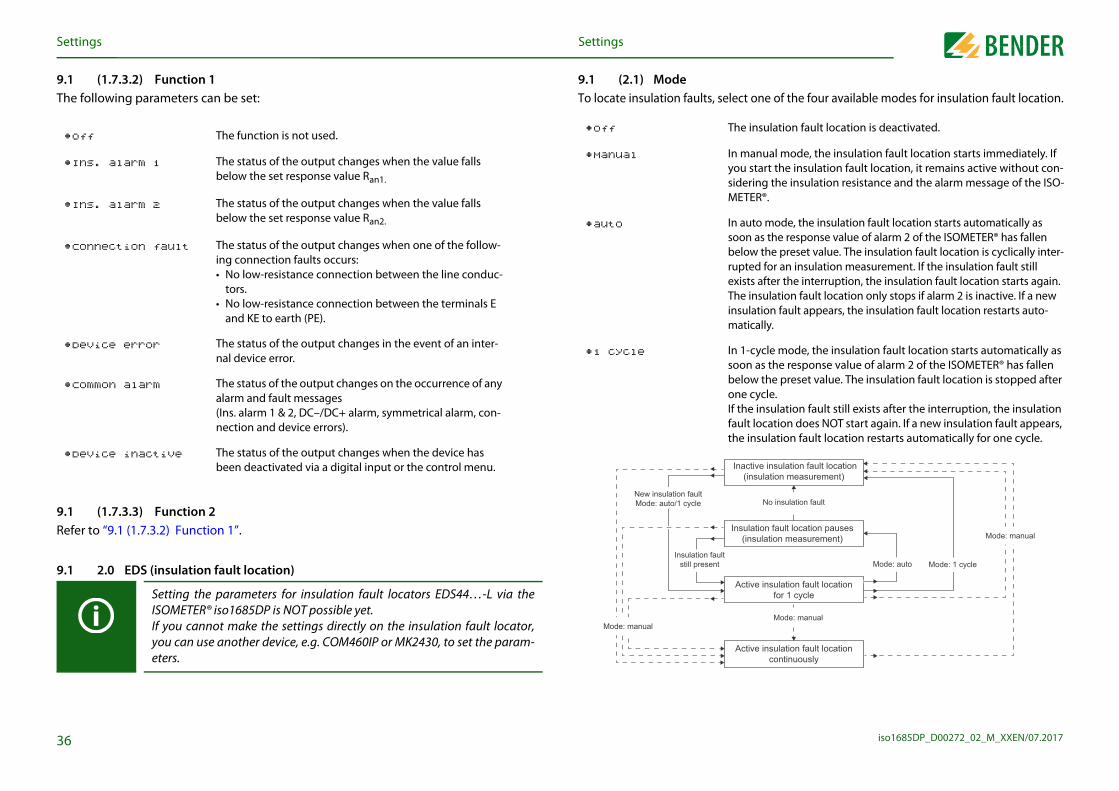
lect one of the four available modes for insulation fault location.
The insulation fault location is deactivated.
In manual mode, the insulation fault location starts immediately. If you start the insulation fault location, it remains active without con-sidering the insulation resistance and the alarm message of the ISO-METER®.
In auto mode, the insulation fault location starts automatically as soon as the response value of alarm 2 of the ISOMETER® has fallen below the preset value. The insulation fault location is cyclically inter-rupted for an insulation measurement. If the insulation fault still exists after the interruption, the insulation fault location starts again. The insulation fault location only stops if alarm 2 is inactive. If a new insulation fault appears, the insulation fault location restarts auto-matically.
In 1-cycle mode, the insulation fault location starts automatically as soon as the response value of alarm 2 of the ISOMETER® has fallen below the preset value. The insulation fault location is stopped after one cycle. If the insulation fault still exists after the interruption, the insulation fault location does NOT start again. If a new insulation fault appears, the insulation fault location restarts automatically for one cycle.
Inactive insulation fault location(insulation measurement)
Active insulation fault locationfor 1 cycle
Insulation fault location pauses(insulation measurement)
Active insulation fault locationcontinuously
No insulation fault
Insulation fault
Mode: manual
Mode: manual
Mode: 1 cycleMode: auto
6
.1 2.0 EDS (insulation fault location)
Setting the parameters for insulation fault locators EDS44…-L via theISOMETER® iso1685DP is NOT possible yet. If you cannot make the settings directly on the insulation fault locator,you can use another device, e.g. COM460IP or MK2430, to set the param-eters.
still present
Mode: manual
Settingsettings
.1 (1.7.3.2) Function 1he following parameters can be set:
.1 (1.7.3.3) Function 2efer to “9.1 (1.7.3.2) Function 1”.
•off The function is not used.
•Ins. alarm 1 The status of the output changes when the value falls below the set response value Ran1.
•Ins. alarm 2 The status of the output changes when the value falls below the set response value Ran2.
•Connection fault The status of the output changes when one of the follow-ing connection faults occurs:• No low-resistance connection between the line conduc-
tors.• No low-resistance connection between the terminals E
and KE to earth (PE).
•Device error The status of the output changes in the event of an inter-nal device error.
•Common alarm The status of the output changes on the occurrence of any alarm and fault messages (Ins. alarm 1 & 2, DC–/DC+ alarm, symmetrical alarm, con-nection and device errors).
•Device inactive The status of the output changes when the device has been deactivated via a digital input or the control menu.
9.1 (2.1) ModeTo locate insulation faults, se
•off
•Manual
•auto
•1 cycle
New insulation faultMode: auto/1 cycle

S
iso1685DP_D00272_02_M_XXEN/07.20173
9
Sm
valuesin measured values for a specific period of time. You can view s. values" menu item. Navigate through the different views :
n run a manual test and reset the alarm messages:
lts detected by the ISOMETER® are displayed. efer to “History memory” auf Seite 31.
sllows configuring the basic settings for the ISOMETER®:
Displays the insulation resistance and chrono-logical sequence.
Displays the current insulation resistance and the system leakage capacitance.
Displays the system voltages.
Displays measuring current, locating current, performance and insulation fault location mode.
Coupling system and locating current injector
Manual device test
Reset of fault and alarm messages
•History Overview of faults that have occurred
Reset the history memory
7
9.1 6.0 Device settingThe device settings menu a
•Delete
Settingsettings
.1 (2.2) Current
et the maximum locating current on the ISOMETER®. You can find the device-specific aximum locating currents in the table below.
Risk of malfunctions due to excessive locating current on sensitivesystem parts!The locating current flowing between the IT system and earth can causecontroller faults in sensitive parts of the system, such as the PLC or relay.Ensure that the level of the locating current is compatible with the systemto be monitored.
•1 mA for EDS441…, EDS461…, EDS491…
•1.5 mA for EDS441…, EDS461…, EDS491…
•2.5 mA for EDS441…, EDS461…, EDS491…
•3 mA for EDS441…, EDS461…, EDS491…
•10 mA for EDS440…, EDS460…, EDS490…
•12.5 mA for EDS440…, EDS460…, EDS490…
•25 mA for EDS440…, EDS460…, EDS490…
•50 mA for EDS440…, EDS460…, EDS490…
9.1 3.0 Data measuredThe ISOMETER® stores certathese data at the "Data meausing the and buttons
9.1 4.0 ControlIn the Control menu, you ca
9.1 5.0 HistoryIn the history menu, the fauFor a detailed description, r
•Data - isoGraph
•Data - Insulation
•Data - Voltage
•Data - PGH
•Data - Temperature
•TEST
•RESET

S
iso1685DP_D00272_02_M_XXEN/07.20173
9Cg
9In
9Bh
9S
meered in the following settings:
format you can set the current date.
te) format to be displayed:
ange between summer time and standard time.
Timege between summer and standard time according to North
ation. summer time begins on each second Sunday in March at by setting the clock forward by one hour from 2:00 to 03:00 mer time always ends the first Sunday in October at 03:00 tting the clock back one hour from 3:00 to 2:00.
n Summer Timege between summer time and standard time according to n regulation.n summer time begins on each last Sunday in March at
etting the clock forward by one hour from 2:00 to 03:00. n summer time always ends on the last Sunday in October setting the clock back one hour from 3:00 to 2:00.
day, month, year
month, day, year
8
Settingsettings
.1 (6.1) Languagehoose the language to be displayed by the ISOMETER®. For example, you can set the lan-uages:
.1 (6.2) Clock the clock menu, you can set the display format of date and time for the ISOMETER®:
.1 (6.2.1) Timeased on the selected time format you can set the current time to display 24-hour or 12-our notation (am/pm).
.1 (6.2.2) Format (time)elect the appropriate time format to be displayed:
•German
•English
•…
•12 h 12-hour notation am/pm
•24 h 24-hour notation
9.1 (6.2.3) Summer tiSummer time can be consid
9.1 (6.2.4) DateBased on the selected date
9.1 (6.2.5) Format (daSelect the appropriate date
•off No automatic ch
•DST Daylight SavingAutomatic chanAmerican regulNorth American02:00 local timelocal time. Sumlocal time by se
•CEST Central EuropeaAutomatic chanCentral EuropeaCentral Europea02:00 CEST by sCentral Europeaat 03:00 CEST by
•dd.mm.yy
•mm-dd-yy
S
iso1685DP_D00272_02_M_XXEN/07.20173
9Sm
9S
9S
9A
9AIfre
9Um
9E
9D
ng, you can open the ISOMETER®'s commissioning wizard again.
e accessed by Bender service staff.
ttings can be viewed in the Info menu. Navigate through the and buttons:
Device name, serial number, article number
Software version measurement technique, software version HMI
Set profile, locating current and EDS mode
Time, date, summer time
Address of the RS-485 interface
9
Settingsettings
.1 (6.3) Interfaceet the parameters for connection of other devices to the ISOMETER® in the interface enu:
.1 (6.3.1) BMSet the parameters for communication with other devices via the BMS bus.
.1 (6.3.1.1) BMS addresselect an address between 1 and 90 for the BMS bus.
.1 (6.4) Displaydjust the display brightness for the ISOMETER® in the display menu:
.1 (6.4.1) Brightnessdjust the display brightness between 0 % and 100 % in steps of 10. no button is pressed on the display for 15 minutes, the brightness of the display will be duced. If now a button is pressed, the normal brightness is restored.
.1 (6.5) Passwordse the password function to protect the device parameters against unauthorised adjust-ent. The default password is 0000.
.1 (6.5.1) Passwordnter an individual four-digit password.
.1 (6.5.2) Statusecide whether the password query should be used:
•on Password query active
•off Password query inactive
9.1 (6.6) CommissioniIn the commissioning menu
9.1 (6.7) ServiceThe service menu can only b
9.1 7.0 InfoThe ISOMETER®'s current sedifferent views using the
•Info - Device
•Info - Software
•Info - Measurement
technique
•Info - Clock
•Info - BMS

S
iso1685DP_D00272_02_M_XXEN/07.20174
9
R
S
In
P
M
I
I
F
C
P
R
R
R
ParameterStatus
E
P
ValueStatus
2
ON
ValueStatus
Mode (operating mode): active highFunction: Test
Mode (operating mode): active highFunction: standby
ValueStatus
from the off
pacitancedepending on the set measurement method (refer to “12. Device profiles”)
off
German
off
0000
0
DS mode auto
GH current 25 mA
Password query
Password
Settingsettings
.2 Factory settings
esponse values, alarms and profile
witching elements
sulation fault location
arameterValueStatus
easurement method Power circuits
nsulation response value Ran1 40kΩ
nsulation response value Ran2 10kΩ
ault memory off
oupling monitoring on
arameterValueStatus
elay 1 (11/12/14)Operating mode: N/C operationFunction: Insulation measurement
elay 2 (21/22/24)Operating mode: N/C operationFunction: Insulation measurement
elay 3 (31/32/34)Operating mode: N/C operationFunction: Device error
Value
BMS
Digital inputs
Other
Parameter
BMS address
BMS termination
Parameter
Digital input 1
Digital input 2
Parameter
Standby mode (disconnectionmains)
Permissible system leakage ca
Buzzer
Menu language

iso1685DP_D00272_02_M_XXEN/07.2017
the BMS bus1
1Tcdete
Amfee
1
maximum length of the RS-485 network: 1200 m
n RS-485 network is a daisy-chain connection. In this connec-o device 2, device 2 to device 3, device 3 to device n etc. The a continuous path without branches.
arrangement:
rrangement:
A1 A2E KE21 22 2431 32 34k l kT ITA B S
RS-485Term.
off on
K3 K2
11 12 14
K1
A B S k I kT IT 31 32 34 21 22 24 11 12 14 E KE A1 A2
A B S
RS-485Term.
off on
CAN 2
A B S
A B S
CAN 2
A B S
41
Wrong arrangementThree examples for wrong a
Device communication via 0. Device communication via the BMS bus
0.1 RS-485 interface with BMS protocol he RS-485 interface, galvanically isolated from the device electronics, serves as a physi-al transmission medium for the BMS protocol. When an ISOMETER® or other bus-capable evices are interconnected via the BMS bus in a network, the BMS bus must be terminat-d at both ends with a 120 Ω resistor. For this purpose, the device is equipped with the rminating switch RS-485 Term. (ON/OFF).
n RS-485 network that is not terminated is likely to become unstable and may result in alfunctions. Only the first and last device in one line may be terminated. Hence, stub eders in the network must not be terminated. The length of the stub feeders is restrict-
d to 1 meter.
0. 2 Topology RS-485 network
1. device … device last device
stub feedermax. 1 m
The optimum topology for ation, device 1 is connected tRS-485 network represents
Correct arrangementThree examples for correct
CAN 1 CAN 2
I2+ I2- I1+ I1-
I2+ I2- I1+ I1-

the BMS busD
iso1685DP_D00272_02_M_XXEN/07.20174
WTS(eCTB
1TtoIn
TmmoA
1Abae"F
twice
on the BMS bus
ur on the bus lines
nnected to the bus
e not activated or connected
of an RS-485 network with BMS protocolA and B of all bus devices in one line
resistors on at the start and the end of the RS-485 network. If e bus is not terminated, connect a 120 Ω resistor to termi-
ge on
ion and address 1 to a bus-capable device
0) to all other bus devices in consecutive order
dress
90) in the device menu via the path:MS/BMS Address.
TER® cannot switch on a potential termination at the BMS bus.h this is not expected to cause communication problems, the should be operated as BMS slave if possible (BMS address > 1). device with master capabilities is available on the bus, the can be set to master (BMS address 1).
ISOMETER® takes over the backup master function after beingswitched on, it waits to see if another master connects itself to the system.
riod: BMS address minus 1 = waiting period in minutes.he iso1685DP has BMS address 3. It waits 3 minus 1 minutes
es) for a master to connect.
2
device receives the MASTER function by assigning Bus address 1 to it.
0.4 BMS master master can query all measured values, alarm and operating messages from a slave. If us address 1 is assigned to a device, this device automatically represents the master, i.e. ll addresses between 1 and 150 are cyclically scanned via the BMS bus for alarm and op-rating messages. If the master detects incorrect answers from a slave, the fault message ault RS-485" will be output via the BMS bus.
Set the BMS address ((1)2…Device settings/Interface/B
Waiting peExample: T(= 2 minut
Device communication via evice communication via the BMS bus
iringhe following type of wiring is recommended for the RS-485 network:hielded cable, core diameter ≥ 0.8 mm.g. J-Y(St)Y 2x0.8), shield connected to earth (PE) on one end.onnection to terminals A and B.he number of bus nodes is restricted to 32 devices. If more devices are to be connected, ender recommends the use of a DI1 repeater.
0.3 BMS protocolhis protocol is an essential part of the Bender measuring device interface (BMS bus pro-col). Data transmission generally makes use of ASCII characters.terface data are:
• Baud rate: 9600 baud
• Transmission: 1 start bit, 7 data bits, 1 parity bit, 1 stop bit (1, 7, E, 1)
• Parity: even
• Checksum: sum of all transmitted bytes = 0 (without CR and LF)
he BMS bus protocol works according to the master-slave principle. Only one master ay exist in each network. All bus devices are identified by a unique BMS address. The aster cyclically scans all other slaves on the bus, listens to their signals and then carries
ut the corresponding commands.
���
� ��
�� ��
Fault causes may be:
• Addresses are assigned
• A second master exists
• Interference signals occ
• A defective device is co
• Terminating resistors ar
10.5 Commissioning • Interconnect terminals
• Switch the terminating a device at the end of thnals A and B
• Switch the supply volta
• Assign the master funct
• Assign addresses (2…9
10.6 Setting BMS ad
The ISOMEEven thougISOMETER®If no otherISOMETER®
Before the

the BMS busD
iso1685DP_D00272_02_M_XXEN/07.20174
1Mm
1
A
A
C
C
D
Si
Oc
Oc
O
ges
essagesd as alarm messages on the BMS bus.
t via the device menu. If the error continues to exist, the mes-n. The error can also be reset by means of the acknowledge-S bus.
annel Description
1Current insulation resistance RF (when RF > (Ran1 + hysteresis))
2Current insulation resistance RF (when RF > (Ran2 + hysteresis))
4 Leakage capacitance Ce in nF, μF
5 Current system voltage UN
6 Current partial voltage terminal L1/+ to earth
7 Current partial voltage terminal L2/– to earth
8Current PGH locating current (when the EDS system is active)
10 Current temperature of the coupling L1/+
11 Current temperature of the coupling L2/–
12 Current temperature of the locating current injector
3
Device communication via evice communication via the BMS bus
0.7 Alarm and operating messages via the BMS busessages are transmitted to a maximum of 12 BMS channels. All alarm and operating essages that may occur are described below.
0.7.1 Alarm messages
Message Channel Description
larm 1 (insulation fault) 1Insulation resistance "prewarning" (Value < response value 1, RF < Ran1)
larm 2 (insulation fault) 2Insulation resistance "alarm" (Value < response value 2, RF < Ran2)
onnection system 4 Connection fault system
onnection PE 5 Connection fault earth
evice error 7 Internal device error
tart nsulation fault location
The insulation fault location is started
vertemperatureoupling
10 Overtemperature coupling terminal L1/+
vertemperatureoupling
11 Overtemperature coupling terminal L2/–
vertemperature PGH 12 Overtemperature of the locating current injector
10.7.2 Operating messa
10.7.3 Resetting error mRecorded errors are provideThe fault messages are resesage will be generated agaiment command via the BM
Message Ch
Insulation resistance
Insulation resistance
Leakage capacitance
Mains voltage
Partial voltage U+/PE
Partial voltage U-/PE
PGH current
Temperature coupling
Temperature coupling
Temperature PGH

the BMS busD
iso1685DP_D00272_02_M_XXEN/07.20174
1Tc
Be
Load factory settings
Programme sequence locating current injector
Restart the device
Programme sequence voltage meas-urement
Restart the device
Programme sequence temperature measurement
Restart the device
Programme sequence history memory Restart the device
Programme sequence console Restart the device
Programme sequence self test Restart the device
Stack error Restart the device
Internal programme sequence Restart the device
Internal programme sequence Restart the device
Fault Action
4
9.63 Parameters Locating current injector and set parameters again
9.64 Parameters Voltage measurement Contact service
9.70 System General software error Restart the device
9.71 System Control flow Restart the device
9.72 SystemProgramme sequence insulation measurement
Restart the device
Device communication via evice communication via the BMS bus
0.7.4 Error codeshe following list contains all relevant error codes output via the BMS bus. The right-hand olumn describes the relevant action to be taken in each case.
MSrror code Components Fault Action
0.30 Connection Connection earth (E/KE) Check connection
0.40 Connection Connection system (L1/+, L2/–) Check connection
4.05 ParameterIncorrect measurement method selected
Change measure-ment method
7.63 System Timeout system management Restart the device
8.11 Hardware Self test insulation measurement Contact service
8.12 Hardware Hardware measuring voltage source Replace device
8.31 Hardware PGH: locating current too high Replace device
8.32 HardwarePGH: locating current cannot be switched off
Replace device
8.42 Hardware Supply voltage ADC Replace device
8.43 Hardware Supply voltage +12 V Replace device
8.44 Hardware Supply voltage –12 V Replace device
8.45 Hardware Supply voltage +5 V Replace device
8.46 Hardware Supply voltage +3.3 V Replace device
9.61 Parameters Insulation measurementLoad factory settings and set parameters again
9.74 System
9.75 System
9.76 System
9.77 System
9.78 System
9.79 System
9.80 System
9.81 System
9.82 System
BMSerror code Components

iso1685DP_D00272_02_M_XXEN/07.2017
1
1Asucmsu
1
CcFthlo
ST(s9FtoF
1TF
pping the insulation fault location can be started and stopped via different interfaces:
rding start and stop conditions of the insulation fault loca-” auf Seite 36.
45
Insulation fault location1. Insulation fault location
1.1 General descriptionn additional function of the ISOMETER® in combination with the EDS is the selective in-lation fault location. The insulation faults detected in the IT system by the ISOMETER®
an be located by means of an EDS and measuring current transformers. For further infor-ation regarding the operating principle of the insulation fault location, refer to 3.3.2 “In-lation fault location” auf Seite 14.
1.2 Required settings for insulation fault location
onnecting and commissioning the system consisting of ISOMETER® and EDS orrectly. or further information regarding the connection of the EDS, refer to 5.2.3 “Connecting e EDS to the ISOMETER®” ab Seite 21, at6. 2 “Commissioning flow chart insulation fault cation” auf Seite 25 and to the corresponding manual of the EDS.
etting locating current and EDS mode.hese settings can be made either during initial commissioning ee 6.3 “Initial commissioning” ab Seite 26) or in the device menu of the ISOMETER® (see .1 2.0 “EDS (insulation fault location)” ab Seite 36).or further information regarding the locating current for insulation fault location, refer 9.1 (2.2) “Current” auf Seite 37.
or further information regarding EDS modes, refer to 9.1 (2.1) “Mode” auf Seite 36.
1.3 Indication on the displayhe active insulation fault location is indicated on the display of the ISOMETER®.or further information, refer to 7. 7 “Insulation fault location” ab Seite 31.
11.4 Starting and stoThe insulation fault location
• Device menu
• Digital input
For further information regation, refer to 9.1 (2.1) “Mode

iso1685DP_D00272_02_M_XXEN/07.2017
mic frequency changes.able for all systems primarily with constant mains frequencies and hen using inverters and dynamic frequency control, select
r < 10 Hz.
age capacitances, e.g. ship applications, the impact of leakage ring result can be significantly reduced by selecting this profile.
ms with dynamic frequency control by inverters in the range 10 ise the measurement with respect to the measuring time and
mely low-frequency control in the range of up to 1…460 Hz and changing extraneous DC voltages due to dynamic load condi-nuous insulation monitoring can be optimised using this profile.
leakage capacitances, e.g. in large-scale photovoltaic systems, measurement.
46
12. Device profiles
Nominal system voltage Mains frequency
System leakage capacitance
Measuring voltage Description
Power circuits AC 0…1000 V/DC 0…1500 V
DC, 15…460 Hz 0…150 μF ±50 V
Main circuits without dynaThe universal profile is suitextraneous DC voltages. WInverter > 10 Hz or Inverte
High capacitance AC 0…1000 V/DC 0…1500 V
DC, 15…460 Hz 0…500 μF ±50 VFor systems with high leakcapacitances on the measu
Inverter > 10 Hz AC 0…1000 V/DC 0…1500 V
DC, 10…460 Hz 0…150 μF ±50 VThis profile is used for systeto 460 Hz in order to optimquality.
Inverter < 10 Hz AC 0…1000 V/DC 0…1500 V
DC, 1…460 Hz 0…150 μF ±50 VFor systems involving extrevery low and continuouslytions in an IT system, conti
Fast 2000 μF AC 0…1000 V/DC 0…1500 V
DC, 15…460 Hz 0…2000 μF ±50 VFor systems with very highthis profile ensures correct
The response value range changes depending on the selected profile. Re-fer to “Response values for insulation monitoring” auf Seite 54.

iso1685DP_D00272_02_M_XXEN/07.2017
Reference LED indicators
ate it.See chapter “Alarm messages” ab Seite 47.
ALARM 1 is lit
ate it.See chapter “Alarm messages” ab Seite 47.
ALARM 2 is lit
e IT system See chapter “Connection” ab Seite 20.
ALARM 1 + ALARM 2 flash in common mode
E)See chapter “Connection” ab Seite 20.
ALARM 1 + ALARM 2 flash in common mode
SERVICE is lit
self again SERVICE is lit
SERVICE is lit
See chapter “Clock” ab Seite 38.
47
13. Alarm messages
Alarm message Description Actions
Alarm 1 (insulation fault)The insulation resistance is lower than the response value Ran1
• Determine cause of the insulation fault and elimin
Alarm 2 (insulation fault)The insulation resistance is lower than the response value Ran2
• Determine cause of the insulation fault and elimin
Connection systemConnection fault system (available from software version 2.x)
• Check the wiring of terminals L1/+, and L2/– to th• Press the test button• Check mains voltage• Check fuses
Connection PE Connection fault. E/KE not connected to PE• Check the wiring of terminals E and KE to earth (P• Press the test button
Device error x Internal device error• Press the TEST button• Switch the supply voltage off and on• Contact Bender service
Overtemperaturecoupling
Overtemperature coupling terminal L1/+ or L2/–• Check mains voltage level. The device connects it
automatically after the cool-down period
Overtemperature PGH Overtemperature of the locating current injector • Wait for the end of the cool-down period
Check date and time! Date and time have not been set yet• Set local date and time
(buffer of three days in case of voltage failure)

iso1685DP_D00272_02_M_XXEN/07.2017
1000
Ce � 1μF
Ce � 10μF
Ce � 100μF
������������������ !
48
14. Diagrams
14.1 Response time profile Power circuits
1
10
100
0,1 1 10 100
Response value Ran [k�]
Res�
����
�
�� an
[s]
����������������� �������������������������� ������������������������������������(p�o"��:�#�$������� ���)

D
iso1685DP_D00272_02_M_XXEN/07.20174
1
100
Ce � 1μF
Ce � 50μF
Ce � 100μF
Ce � 500μF
��������������������� !
iagrams
9
4.2 Response time profile High capacitance
10
100
1000
0,1 1 10
Response value Ran [k�]
���
����
�
�� a
n[s
]
����������������� ������������������������ ���������������������������������(p�o"��: H��� �����������)

D
iso1685DP_D00272_02_M_XXEN/07.20175
1
1000
Ce � 1μF
Ce � 10μF
Ce � 100μF
������������������� !
iagrams
0
4.3 Response time profile Inverter > 10 Hz
1
10
100
0,1 1 10 100
����������������� �������������������������� �����������������������������������(p�o"��:����������&��'�*+)
Response value Ran [k�]
Res�
����
�
�� an
[s]
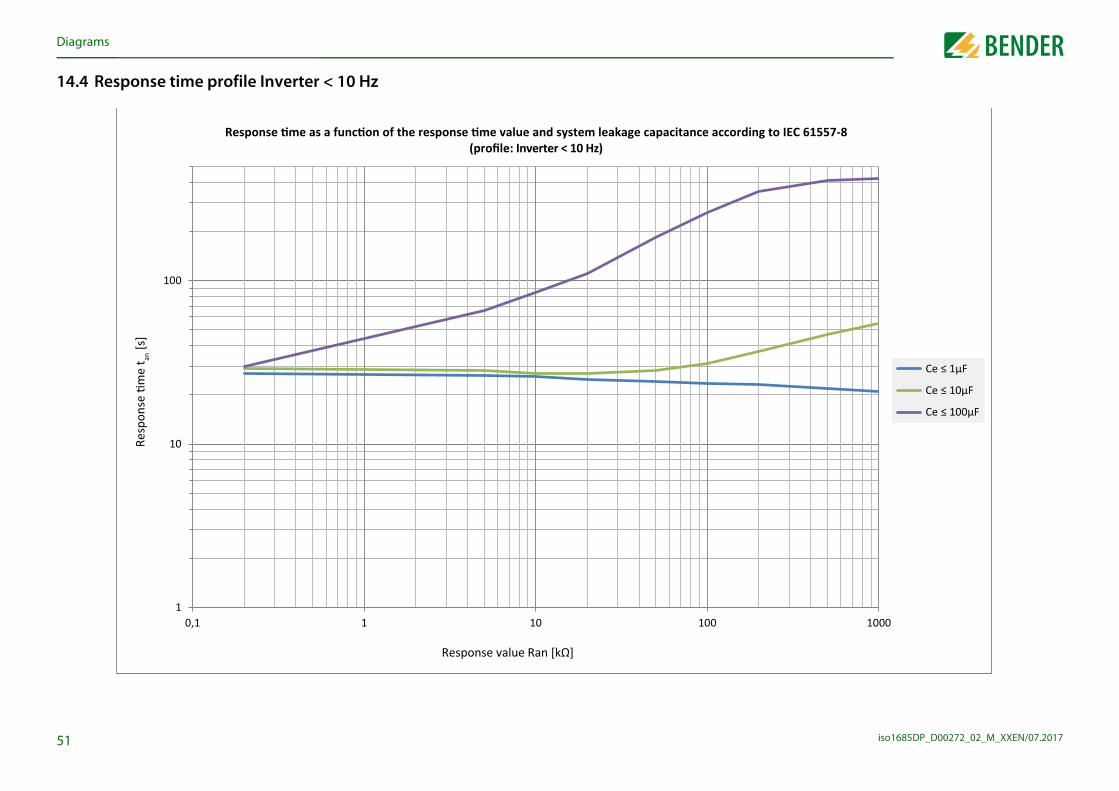
D
iso1685DP_D00272_02_M_XXEN/07.20175
1
1000
Ce � 1μF
Ce � 10μF
Ce � 100μF
������������������� !
iagrams
1
4.4 Response time profile Inverter < 10 Hz
1
10
100
0,1 1 10 100
����������������� �������������������������� �����������������������������������(p�o"��:����������,��'�*+)
Response value Ran [k�]
Res�
����
�
�� an
[s]

D
iso1685DP_D00272_02_M_XXEN/07.20175
1
100
Ce � 1μF
Ce � 10μF
Ce � 100μF
Ce � 1000μF
Ce � 2000μF
������������������ !
iagrams
2
4.5 Response time profile Fast 2000 μF
10
100
1000
0,1 1 10
Response value Ran [k�]
Res�
����
�
�� a
n[s
]����������������� �������������������������� ������������������������������������
(p�o"��:�-����2000μF)

D
iso1685DP_D00272_02_M_XXEN/07.20175
1
5 0 0
�����������������
��������������������������
�����$����������������������%!&'�����$����������������������()"&'�
iagrams
3
4.6 Leakage capacitance
1
10
100
1000
5 050,5
Capa
cita
nce
[μF]
Fault resistance [k.]
/��� ������������������������������������� ���
��������������������������������������������������������������������������������������������!"��#������������ ���������������������������������!��#�������������

iso1685DP_D00272_02_M_XXEN/07.2017
1
1(
InInRaOvRaRaPoVo
VNoToFrSuFrPo
MMMInImPePeMToFr
Response values for insulation monitoring
= 10 kΩ) and Ce= 1 μF acc. to IEC 61557-8 ...........................................................................
tion fault location (EDS) .................................................................................................................................... ≤ 50 mA....................................................................................................................................... 2 s/4 s
........................................................................... graphic display 127 x 127 pixel, 40 x 40 mm....................................................................................................................... 0.2 kΩ…50 MΩ
......................................................................................................................................... green......................................................................................................................................... yellow......................................................................................................................................... yellow......................................................................................................................................... yellow......................................................................................................................................... yellow
.............................................................................................................. active high, active low...................................................none, test, reset, deactivate device, insulation fault location................................................................................................................................. 10…30 V................................................................................................................................... 0…0.5 V
............................................................................................................................. RS-485/BMS............................................................................................................................. terminals A/B.................................................................................................................................. ≤ 1200 m on one end) ............................................................... 2-core, ³0.6 mm2, e.g. J-Y(St)Y2x0.6................................................................................................................................. terminal STerm. RS-485) .................................................................................................. 120 Ω (0.5 W)....................................................................................................................... (1) 2…90 ( 2)*
54
Response value Ran1 (alarm 1) .......................................................................................................................... 200 Ω…1 MΩ (40 kΩ)∗Response value Ran2 (alarm 2) .......................................................................................................................... 200 Ω…1 MΩ (10 kΩ)∗Condition response value ........................................................................................................................................................Ran1 ≥ Ran2Upper limit of the measuring range when set to Cemax = 2000 μF ............................................................................................... 50 kΩUpper limit of the measuring range when set to Cemax = 500 μF ................................................................................................ 200 kΩRelative uncertainty (10 kΩ…1 MΩ) (acc. to IEC 61557-8)........................................................................................................ ±15 %Relative uncertainty (0.2 kΩ…< 10 kΩ) ...................................................................................................................... ±200 Ω ±15 %Hysteresis ........................................................................................................................................................................................... 25 %
Technical data5. Technical data
5.1 Tabular data iso1685DP)* = Factory settings
sulation coordination acc. to IEC 60664-1/IEC 60664-3sulation coordination according to IEC 60664-1ted voltage.............................................................................................................................................................................. DC 1500 Vervoltage category (OVC)..................................................................................................................................................................... IIIted impulse withstand voltage ...................................................................................................................................................... 8 kV ted insulation voltage...................................................................................................................................................................1500 Vllution degree exterior.......................................................................................................................................................................... 3ltage test, routine test (IEC 61010-1) ......................................................................................................................................... 2.2 kV
oltage rangesminal system voltage range Un ........................................................................................................ AC 0…1000 V/DC 0…1500 Vlerance of Un .........................................................................................................................................................AC +10 %/DC +5 %equency range of Un ..................................................................................................................................................... DC, 1…460 Hzpply voltage Us (see also device nameplate) ................................................................................................................. DC 18…30 V
equency range of Us ........................................................................................................................................................................... DCwer consumption ....................................................................................................................................................................... ≤ 9 W
easuring circuit for insulation monitoringeasuring voltage Um (peak value) ............................................................................................................................................... ±50 Veasuring current Im (at RF = 0 Ω) ........................................................................................................................................... ≤ 1.5 mAternal DC resistance Ri ............................................................................................................................................................... ≥ 70 kΩpedance Zi at 50 Hz .................................................................................................................................................................. ≥ 70 kΩrmissible extraneous DC voltage Ufg................................................................................................................................. ≤ DC 1500 Vrmissible system leakage capacitance Ce .......................................................................................... profile dependent, 0…2000 μFeasuring range leakage capacitance ................................................................................................................................20…2000 μFlerance measurement of Ce ........................................................................................................................................... ±10 % ±10 μFequency range measurement of Ce ............................................................................................................................ DC, 30…460 Hz
Time responseResponse time tan at RF = 0.5 x Ran (Ran profile dependent, typ. 10 s
Measuring circuit for insulaLocating current IL DC .............................Test cycle/pause .......................................
IndicationDisplay......................................................Display range measured value .................
LEDsON (operation LED)...................................PGH ON.....................................................SERVICE ....................................................ALARM 1 ..................................................ALARM 2 ..................................................
Digital inputsOperating mode, adjustable.....................Functions..................................................High level ................................................Low level .................................................
Serial interfaceInterface/protocol ....................................Connection ...............................................Cable length ............................................Shielded cable (shield to functional earthShield.........................................................Terminating resistor, can be connected (Device address, BMS bus .........................

T
iso1685DP_D00272_02_M_XXEN/07.20175
SSwOpOpElCoUtRaRaRaM
CCoCoCoCo
CCoCoCoCoStOp
EEMClStTrLong-term storage (IEC 60721-3-1) .................................................................................................................................................. 1K4ClStTrLoDeAmAmAmAr
............................................................................................................... continuous operation
.............................................................................................. vertical, system coupling on topsure mounting.................................................................................................. 1.0…1.5 Nmts........................................................................................................................................ IP30............................................................................................................................................ IP30........................................................................................................................... polycarbonate
..............................................................................................................................................V-0.................................................................................................................................. ≤ 1600 g
ertificationsd according to the following standards:-8)
nly applies to profile Fast 2000 μF)-9)
-1)
s
are absolute values.
lue range
Nominal voltage Supply voltage * Art. No.
Ω AC 0…1000 VDC 0…1500 V
DC 18…30 V B91065802
5
assification of mechanical conditions acc. to IEC 60721:ationary use (IEC 60721-3-3) for iso1685DP .................................................................................................................................. 3M4ansport (IEC 60721-3-2).................................................................................................................................................................. 2M2ng-term storage (IEC 60721-3-1) .................................................................................................................................................. 1M3viation from the classification of climatic conditions:bient temperature during operation .......................................................................................................................... –40…+70 °Cbient temperature transport ....................................................................................................................................... –40…+80 °Cbient temperature long-term storage ...................................................................................................................... –25 …+80 °C
ea of application .......................................................................................................................................................... ≤ 3000 m AMSL
The data labelled with an *
iso1685DP-425 200 Ω…1 M
Technical dataechnical data
witching elementsitching elements.................. 3 changeover contacts: K1 (insulation fault alarm 1), K2 (insulation fault alarm 2), K3 (device error)erating principle K1, K2 ....................................................................................... N/C operation or N/O operation (N/C operation)*erating principle K3 ....................................................................................................................... N/C operation, cannot be changed
ectrical endurance under rated operating conditions, number of cycles ..................................................................................100,000ntact data acc. to IEC 60947-5-1:ilisation category .................................................................................................... .... AC 13 ..... AC 14..... DC-12.... DC-12 .. DC-12ted operational voltage ......................................................................................... .... 230 V ..... 230 V.........24 V...... 110 V ....220 Vted operational current .......................................................................................... ........ 5 A ......... 3 A.......... 1 A...... 0.2 A .... 0.1 Ated insulation voltage.....................................................................................................................................................................250 Vinimum contact rating ...................................................................................................................................... 1 mA at AC/DC ≥ 10 V
onnection (except system coupling)nnection type....................................................................................................................................... pluggable push-wire terminalsnnection, rigid/flexible...................................................................................................................... 0.2…2.5 mm2/0.2…2.5 mm2
nnection, flexible with ferrule, without/with plastic sleeve..................................................................................... 0.25…2.5 mm2
nductor sizes (AWG) ................................................................................................................................................................ 24…12
onnection of the system couplingnnection type....................................................................................................................................... pluggable push-wire terminalsnnection, rigid/flexible.......................................................................................................................... 0.2…10 mm2/0.2…6 mm2
nnection, flexible with ferrule, without/with plastic sleeve ............................................................. 0.25…6 mm2/0.25…4 mm2
nductor sizes (AWG) .................................................................................................................................................................. 24…8ripping length.............................................................................................................................................................................. 15 mmening force ......................................................................................................................................................................... 90…120 N
nvironment/EMCC ...................................................................................................................................................................................... IEC 61326-2-4
assification of climatic conditions acc. to IEC 60721:ationary use (IEC 60721-3-3) ....................................................................................3K5 (except condensation and formation of ice)ansport (IEC 60721-3-2) .................................................................................................................................................................. 2K3
OtherOperating mode .......................................Position of normal use ..............................Tightening torque of the screws for encloDegree of protection, internal componenDegree of protection, terminals...............Enclosure material ....................................Flammability class ...................................Weight ......................................................
15.2 Standards and cThe iso1685DP was designe- DIN EN 61557-8 (VDE 0413- IEC 61557-8- IEC 61557-8 Appendix C (o- DIN EN 61557-9 (VDE 0413- IEC 61557-9- IEC 61326-2-4- DIN EN 60664-1 (VDE 0110
15.3 Ordering detail
TypeResponse va

iso1685DP_D00272_02_M_XXEN/07.2017
InAAAA
AAaA
BB
BB
CCcC
) 26ve) 27
measurement 26elements 16
) 26
e 17 111
Language 23, 35
r 11
6
Connect the device 19, 20Connection
Connection requirements 17Connections 15Coupling monitoring 31
DDate 23, 35Device buttons 16
LEDsALARM 1 16ALARM 2 16ON 16PGH ON 16SERVICE 16
Locating current injecto
dex
bleitkapazität 50ddress setting 10larm
Messages 44larm messages 40larm relays 11nd certifications 52nsprechzeit
Profil Umrichter 45
MS bus 36, 38Address setting 39Alarm messages 40Commissioning 39Master 39Number of bus nodes 39Operating messages 40Protocol 39
utton/Key 16uttons 16
lock 23, 35ommissioning flow chart 22ommissioning wizard 23
Device features 10DIP switch 16Display 26
Fault display (activeFault display (inactiFault memory 27History memory 28Signal quality of the
Display and operating
FFactory settings 22Function description 10
HHistory memory 28
IIndication 26
Limit values for R(anInputs 31Installation of the devicInsulation fault locationInsulation monitoring 1Interface 36
L

In
iso1685DP_D00272_02_M_XXEN/07.20177
MMMMM
NN
OO
OO
PPPP
P
RRRRS-485 network
SSS
g 315
ation resistance 31
e 341, Ran2 24
asurement 26
ance 43
ork 38
Termination 9
21rical installations 10
Correct arrangement 38Wrong arrangement 38
afety instructions 8elf test 24
after connection to the supply voltage 12Automatic 13
WWiring diagram 19, 20, Work activities on elect
Indexdex
ains frequency 43easured value transmission 12easured values 34emory card 16
ominal system voltage 43
perating elementsButton/Key 16DIP switch 16Memory card 16
perating messages 40utput 32
arameterisation of the insulation fault location 11assword 36rofil
Umrichter 45, 47, 48, 49rofile overview 43
esetting error messages 40S-485 interface 38
Manual 13Service menu 36Settings
Alarm 30Basic settings 34Coupling monitorinDate and time 23, 3Inputs 31Interface 36Language 23, 35Manual test 34Measured values 34Measurement insulPassword 36Profile 24, 30Reset alarm messagResponse value RanSystem type 23
Signal quality of the meStandards 52Standby mode 12System leakage capacit
Tterminated RS-485 netwTerminating resistor 38


Fotos: Bender Archiv und bendersystembau Archiv.
KundendienstService-Hotline: 0700-BenderHelp (Telefon und Fax)Carl-Benz-Straße 8 • 35305 Grünberg • Germany
Tel.: +49 6401 807-760Fax: +49 6401 807-629
E-Mail: [email protected]: http://www.bender.de BENDER Group
Bender GmbH & Co. KGPostfach 1161 • 35301 Grünberg • GermanyLondorfer Straße 65 • 35305 Grünberg • Germany
Tel.: +49 6401 807-0Fax: +49 6401 807-259
E-Mail: [email protected]: www.bender.de