isolators, rabs and mobile clean rooms in aseptic processing
TRANSCRIPT

Isolators, RABs and Mobile Clean Rooms in Aseptic
Processing Gary Partington
Walker Barrier Systems [email protected]
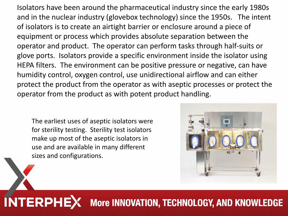
Isolators have been around the pharmaceutical industry since the early 1980s and in the nuclear industry (glovebox technology) since the 1950s. The intent of isolators is to create an airtight barrier or enclosure around a piece of equipment or process which provides absolute separation between the operator and product. The operator can perform tasks through half-suits or glove ports. Isolators provide a specific environment inside the isolator using HEPA filters. The environment can be positive pressure or negative, can have humidity control, oxygen control, use unidirectional airflow and can either protect the product from the operator as with aseptic processes or protect the operator from the product as with potent product handling.
The earliest uses of aseptic isolators were for sterility testing. Sterility test isolators make up most of the aseptic isolators in use and are available in many different sizes and configurations.
Aseptic processing using isolation systems separates the external clean room environment from the aseptic processing line and minimizes its exposure to personnel. A well-designed positive pressure isolator, supported by adequate procedures for its maintenance, monitoring, and control, offers tangible advantages over traditional aseptic processing, including fewer opportunities for microbial contamination during processing. The guidance expands on such areas as: • Materials of Construction • Airflow/pressure differential/air classification • Glove Integrity • Transfer of Materials/supplies • Decontamination • Environmental Monitoring
Guidance for Industry Sterile Drug Products Produced by Aseptic Processing — Current Good Manufacturing Practice
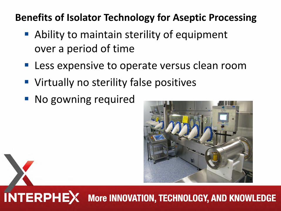
Ability to maintain sterility of equipment over a period of time
Less expensive to operate versus clean room Virtually no sterility false positives No gowning required
Benefits of Isolator Technology for Aseptic Processing
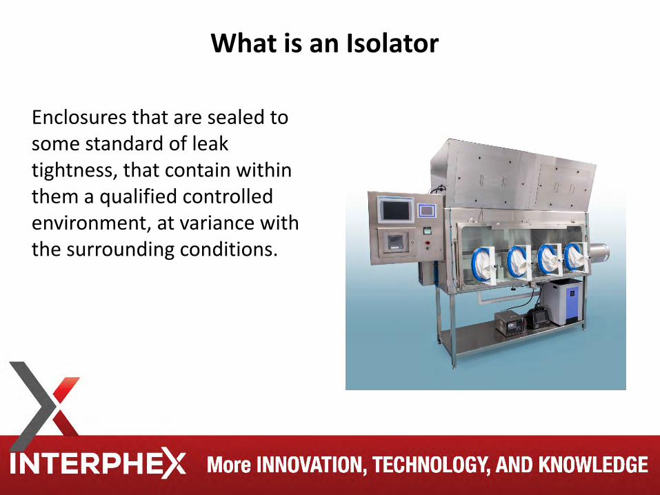
Enclosures that are sealed to some standard of leak tightness, that contain within them a qualified controlled environment, at variance with the surrounding conditions.
What is an Isolator
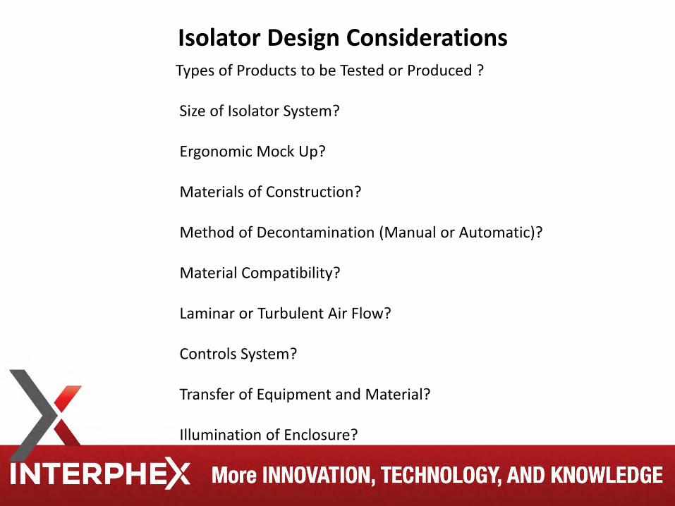
Types of Products to be Tested or Produced ? Size of Isolator System? Ergonomic Mock Up? Materials of Construction? Method of Decontamination (Manual or Automatic)? Material Compatibility? Laminar or Turbulent Air Flow? Controls System? Transfer of Equipment and Material? Illumination of Enclosure?
Isolator Design Considerations
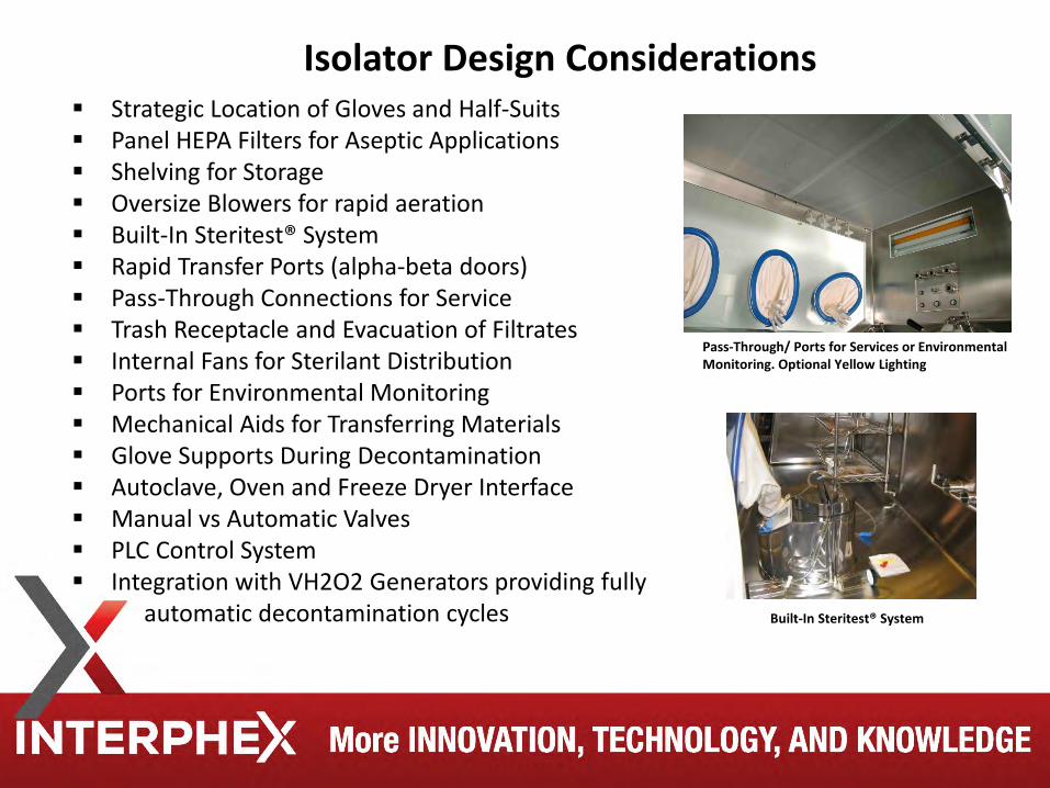
Strategic Location of Gloves and Half-Suits Panel HEPA Filters for Aseptic Applications Shelving for Storage Oversize Blowers for rapid aeration Built-In Steritest® System Rapid Transfer Ports (alpha-beta doors) Pass-Through Connections for Service Trash Receptacle and Evacuation of Filtrates Internal Fans for Sterilant Distribution Ports for Environmental Monitoring Mechanical Aids for Transferring Materials Glove Supports During Decontamination Autoclave, Oven and Freeze Dryer Interface Manual vs Automatic Valves PLC Control System Integration with VH2O2 Generators providing fully automatic decontamination cycles
Pass-Through/ Ports for Services or Environmental Monitoring. Optional Yellow Lighting
Built-In Steritest® System
Isolator Design Considerations
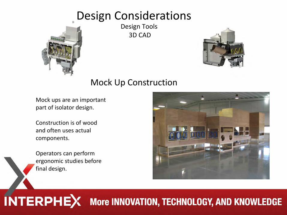
Design Tools
3D CAD
Mock Up Construction
Mock ups are an important part of isolator design. Construction is of wood and often uses actual components. Operators can perform ergonomic studies before final design.
Design Considerations

Mock Up Construction
It is important to involve the end user in the mock up evaluation
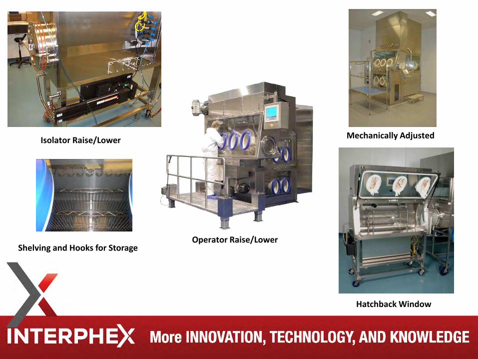
Shelving and Hooks for Storage
Hatchback Window
Isolator Raise/Lower Mechanically Adjusted
Operator Raise/Lower
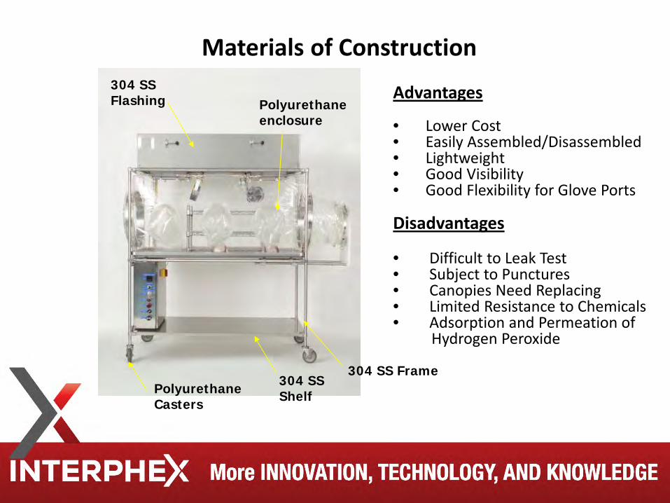
Materials of Construction
304 SS Frame Polyurethane Casters
Polyurethane enclosure
304 SS Shelf
304 SS Flashing Advantages
• Lower Cost • Easily Assembled/Disassembled • Lightweight • Good Visibility • Good Flexibility for Glove Ports Disadvantages • Difficult to Leak Test • Subject to Punctures • Canopies Need Replacing • Limited Resistance to Chemicals • Adsorption and Permeation of Hydrogen Peroxide
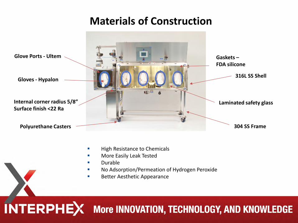
High Resistance to Chemicals More Easily Leak Tested Durable No Adsorption/Permeation of Hydrogen Peroxide Better Aesthetic Appearance
Gaskets – FDA silicone
Laminated safety glass
304 SS Frame Polyurethane Casters
Gloves - Hypalon
Glove Ports - Ultem
316L SS Shell
Internal corner radius 5/8” Surface finish <22 Ra
Materials of Construction
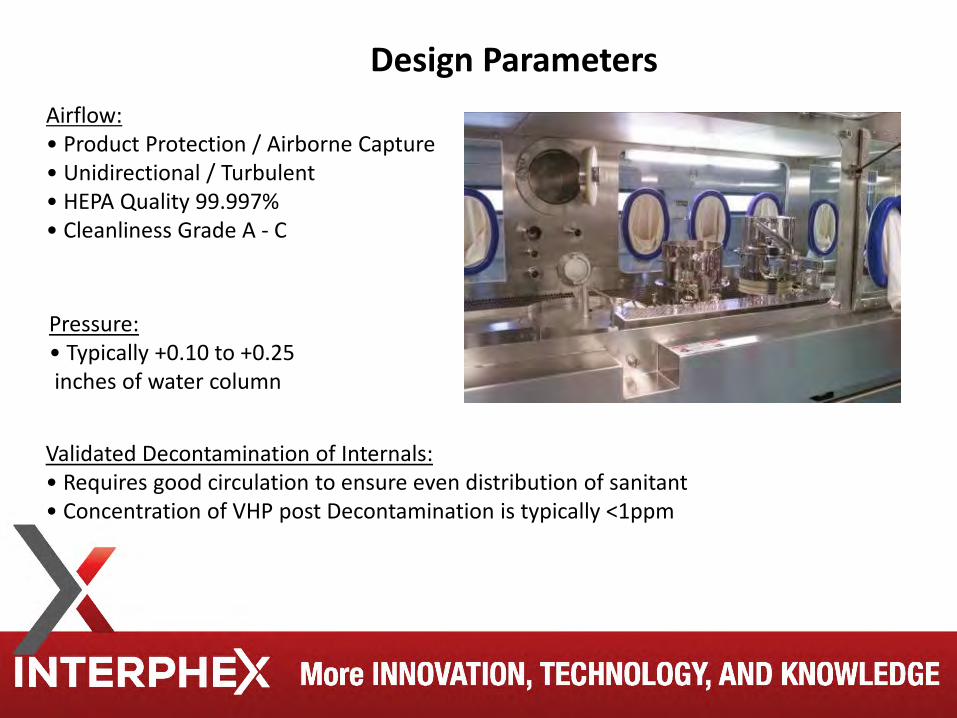
Airflow: • Product Protection / Airborne Capture • Unidirectional / Turbulent • HEPA Quality 99.997% • Cleanliness Grade A - C
Pressure: • Typically +0.10 to +0.25 inches of water column
Validated Decontamination of Internals: • Requires good circulation to ensure even distribution of sanitant • Concentration of VHP post Decontamination is typically <1ppm
Design Parameters
Classified room not required. Limit access to non essential staff. Provide adequate space around isolators for maintenance, staging
and moving of transfer isolators. Temperature and RH control of room is important, but no
environmental monitoring of room is required. Uniform temperature conditions in room required so not to affect
isolator sterilization methods.
Location
Air Handling Systems HEPA filters are required. Meets Class 100 conditions at rest for sterility test and during
operation for filling lines (UAF). Constant air over pressure required. Unidirectional (filling lines) or turbulent (sterility testing). The 2003 European Commission Guide to GMP (Revision to Annex 1)
refers to laminar air flow (aka unidirectional) in isolators, but it deals with the “manufacture” of sterile medicinal products. There is no requirement for laminar air flow in a sterility test isolator.
Turbulent airflow isolators have been used in sterility testing since the early 1980s and are still manufactured today.
Typically no requirement for air velocity or air changes exist on sterility test isolators.
Sterility test isolators are closed systems. The 2004 Aseptic Processing Guide, still in use today says: “Turbulent flow can be acceptable within closed isolators, which are normally compact in size and do not house processing lines. Other aseptic processing isolators employ unidirectional airflow that sweeps over and away from exposed sterile materials, avoiding any turbulence or stagnant airflow in the area of exposed sterilized materials, product, and container closures. In most sound designs, air showers over the critical area once and then is systematically exhausted from the enclosure. The air handling system should be capable of maintaining the requisite environmental conditions within the isolator.”
Air Handling Systems
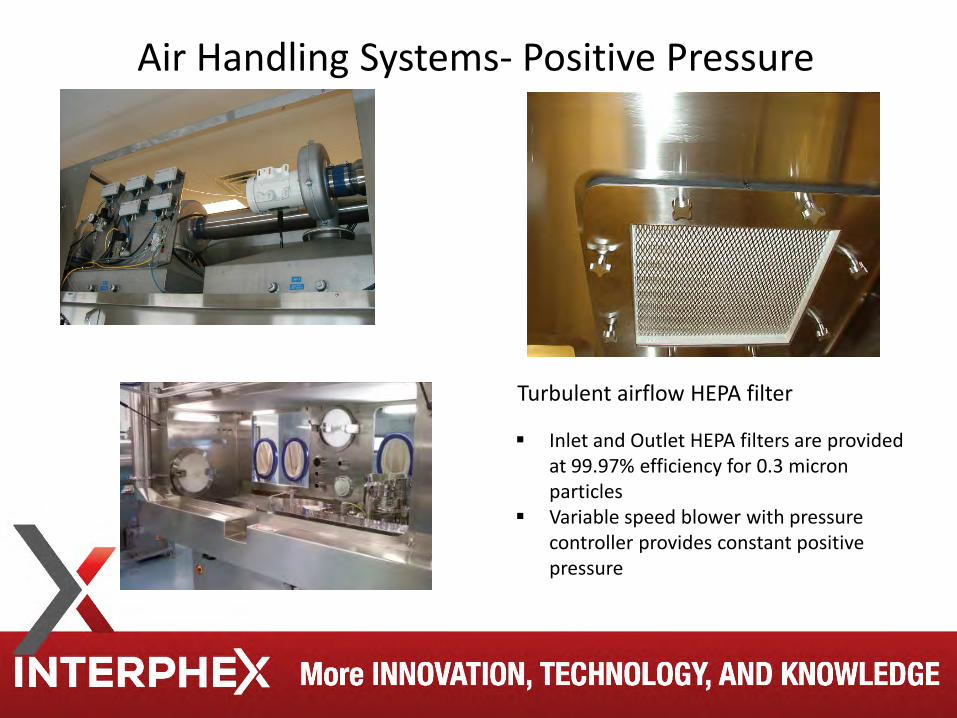
Air Handling Systems- Positive Pressure
Turbulent airflow HEPA filter
Inlet and Outlet HEPA filters are provided at 99.97% efficiency for 0.3 micron particles
Variable speed blower with pressure controller provides constant positive pressure
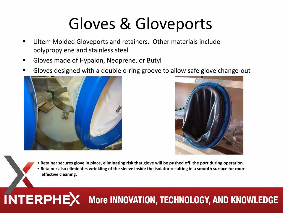
Gloves & Gloveports Ultem Molded Gloveports and retainers. Other materials include
polypropylene and stainless steel Gloves made of Hypalon, Neoprene, or Butyl Gloves designed with a double o-ring groove to allow safe glove change-out
• Retainer secures glove in place, eliminating risk that glove will be pushed off the port during operation. • Retainer also eliminates wrinkling of the sleeve inside the isolator resulting in a smooth surface for more effective cleaning.
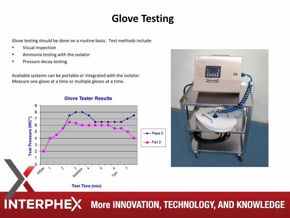
Glove Testing
Glove testing should be done on a routine basis. Test methods include: Visual inspection Ammonia testing with the isolator Pressure decay testing
Available systems can be portable or integrated with the isolator. Measure one glove at a time or multiple gloves at a time.
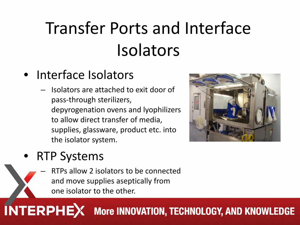
Transfer Ports and Interface Isolators
• Interface Isolators – Isolators are attached to exit door of
pass-through sterilizers, depyrogenation ovens and lyophilizers to allow direct transfer of media, supplies, glassware, product etc. into the isolator system.
• RTP Systems – RTPs allow 2 isolators to be connected
and move supplies aseptically from one isolator to the other.
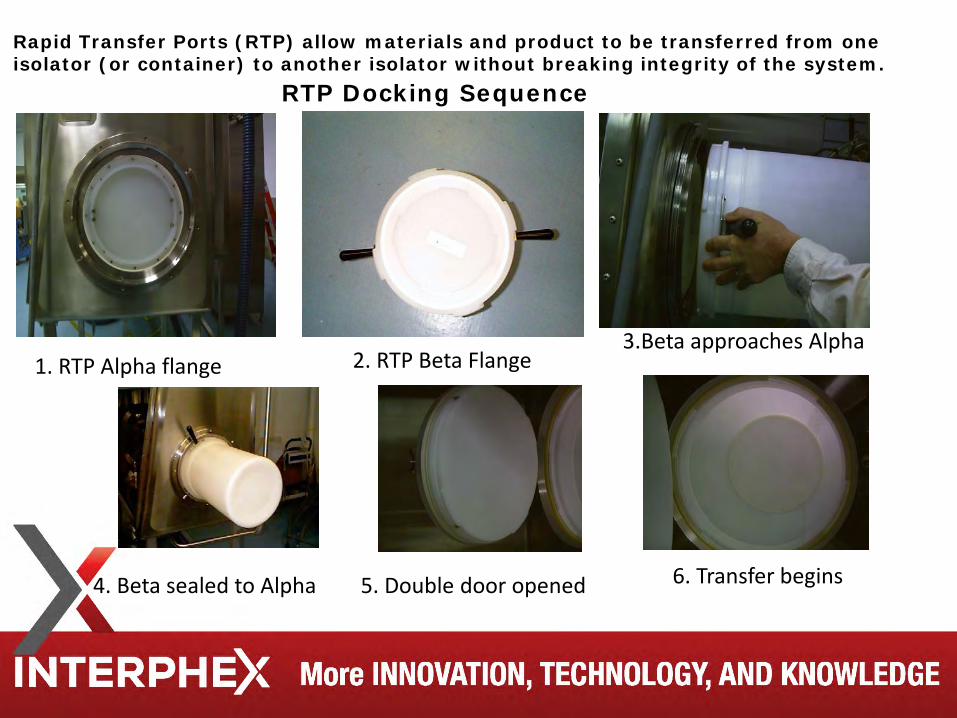
Rapid Transfer Ports (RTP) allow materials and product to be transferred from one isolator (or container) to another isolator without breaking integrity of the system.
RTP Docking Sequence
1. RTP Alpha flange 2. RTP Beta Flange 3.Beta approaches Alpha
4. Beta sealed to Alpha 5. Double door opened 6. Transfer begins
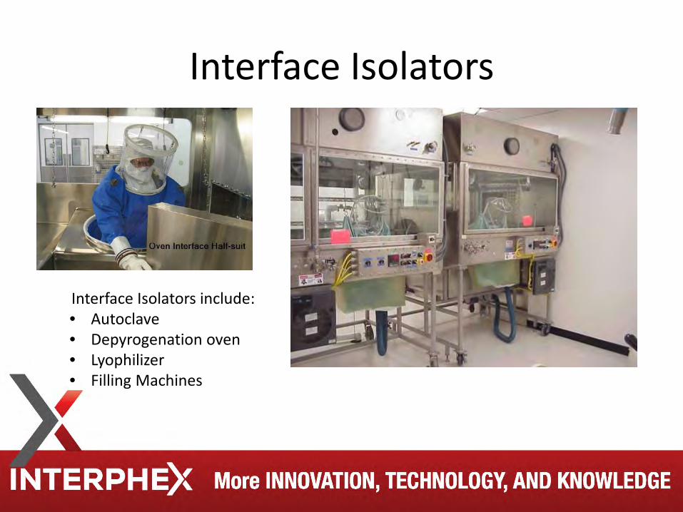
Interface Isolators
Interface Isolators include: • Autoclave • Depyrogenation oven • Lyophilizer • Filling Machines
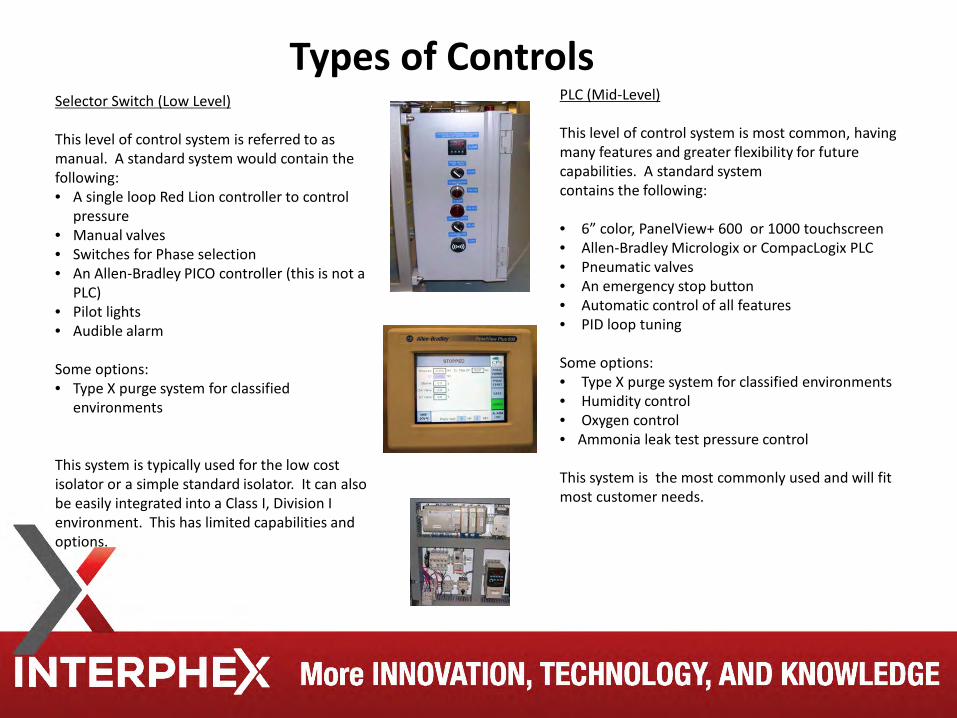
Selector Switch (Low Level) This level of control system is referred to as manual. A standard system would contain the following: • A single loop Red Lion controller to control
pressure • Manual valves • Switches for Phase selection • An Allen-Bradley PICO controller (this is not a
PLC) • Pilot lights • Audible alarm Some options: • Type X purge system for classified
environments This system is typically used for the low cost isolator or a simple standard isolator. It can also be easily integrated into a Class I, Division I environment. This has limited capabilities and options.
Types of Controls PLC (Mid-Level) This level of control system is most common, having many features and greater flexibility for future capabilities. A standard system contains the following: • 6” color, PanelView+ 600 or 1000 touchscreen • Allen-Bradley Micrologix or CompacLogix PLC • Pneumatic valves • An emergency stop button • Automatic control of all features • PID loop tuning Some options: • Type X purge system for classified environments • Humidity control • Oxygen control • Ammonia leak test pressure control This system is the most commonly used and will fit most customer needs.
The use of barrier isolator technology for sterility testing of pharmaceuticals and medical devices has clearly demonstrated the ability to significantly decrease and even eliminate the incidence of “false positive” results. The superior testing results have not only increased laboratory testing confidence but have also decreased overall operation costs.
Aseptic Isolators – Sterility Testing
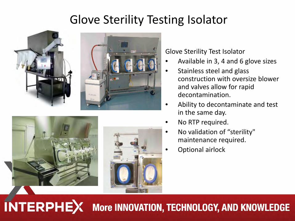
Glove Sterility Testing Isolator
Glove Sterility Test Isolator • Available in 3, 4 and 6 glove sizes • Stainless steel and glass
construction with oversize blower and valves allow for rapid decontamination.
• Ability to decontaminate and test in the same day.
• No RTP required. • No validation of “sterility"
maintenance required. • Optional airlock
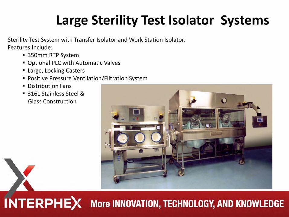
Sterility Test System with Transfer Isolator and Work Station Isolator. Features Include:
350mm RTP System Optional PLC with Automatic Valves Large, Locking Casters Positive Pressure Ventilation/Filtration System Distribution Fans 316L Stainless Steel & Glass Construction
Large Sterility Test Isolator Systems
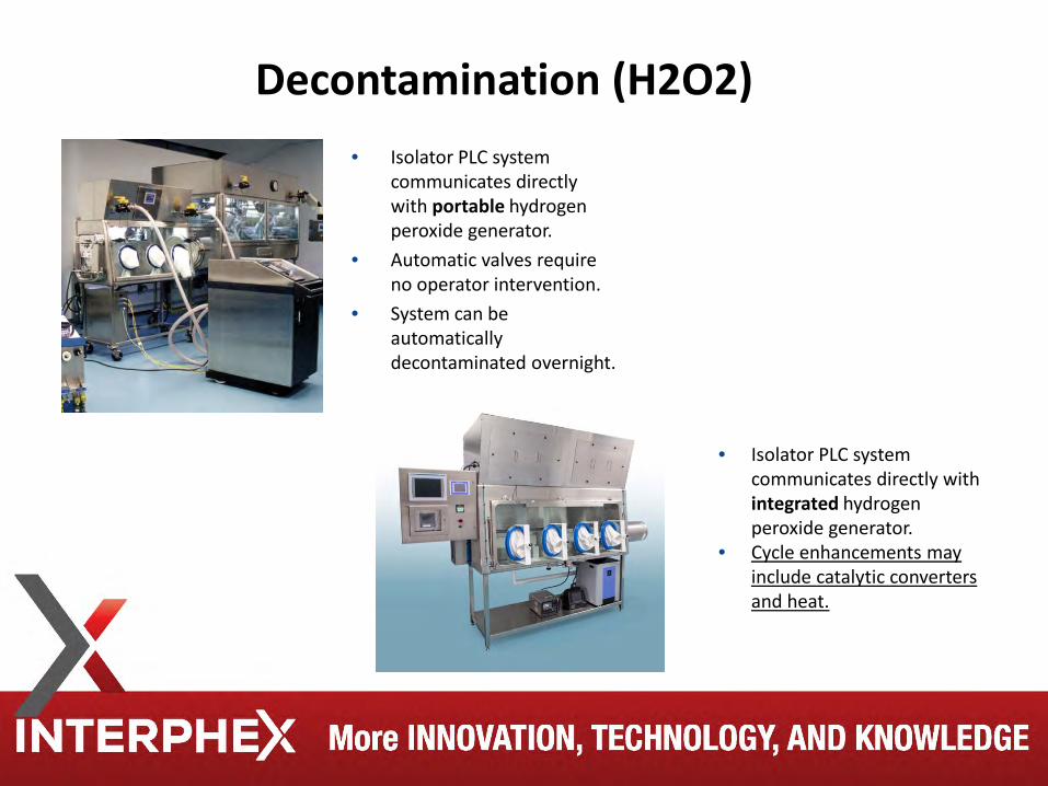
Decontamination (H2O2) • Isolator PLC system
communicates directly with portable hydrogen peroxide generator.
• Automatic valves require no operator intervention.
• System can be automatically decontaminated overnight.
• Isolator PLC system communicates directly with integrated hydrogen peroxide generator.
• Cycle enhancements may include catalytic converters and heat.
Decontamination (other agents) • Chlorine Dioxide is widely used in decontaminating in the animal
research enclosures. • Nitrogen Dioxide is being tested for use in the pharmaceutical industry o NO2 has a much lower oxidation potential (-0.8
V) than other sterilants (not principle mechanism of microbial inactivation)
o Stable in the vapor form
o Initial studies show faster cycle times than other agents
o Low temperature and pressure requirements
o Material compatibility should be verified
o Residuals easily removed via aeration (minimal absorption)
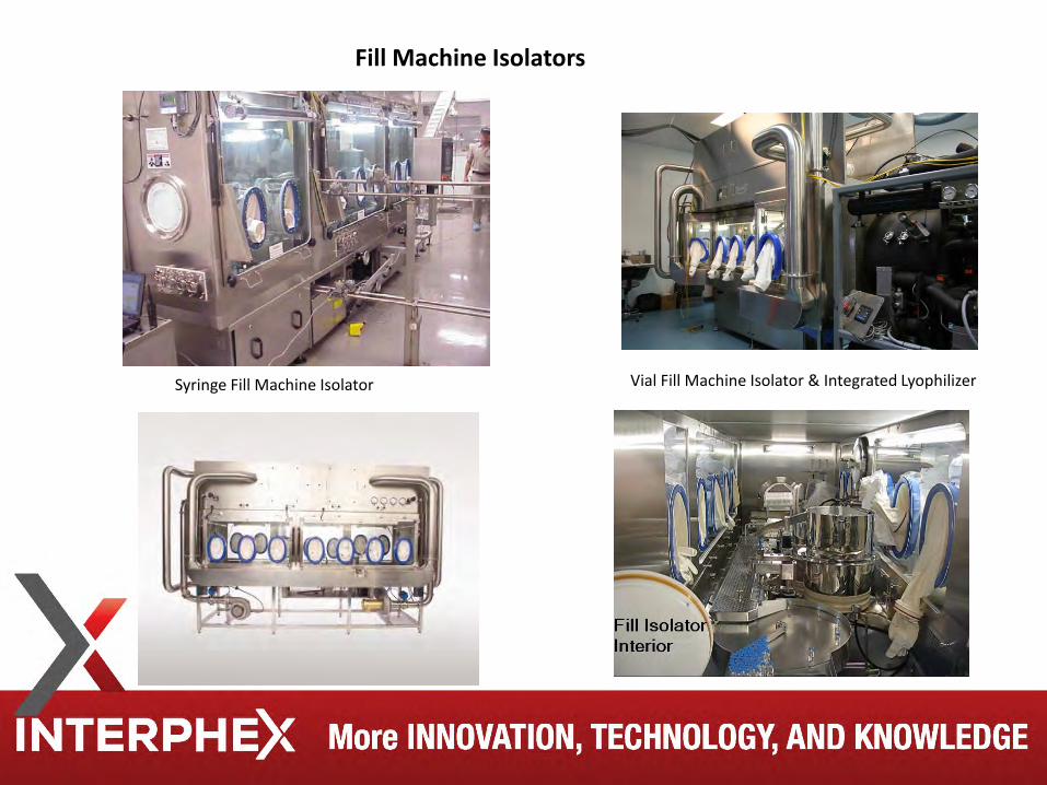
Fill Machine Isolators
Vial Fill Machine Isolator & Integrated Lyophilizer Syringe Fill Machine Isolator
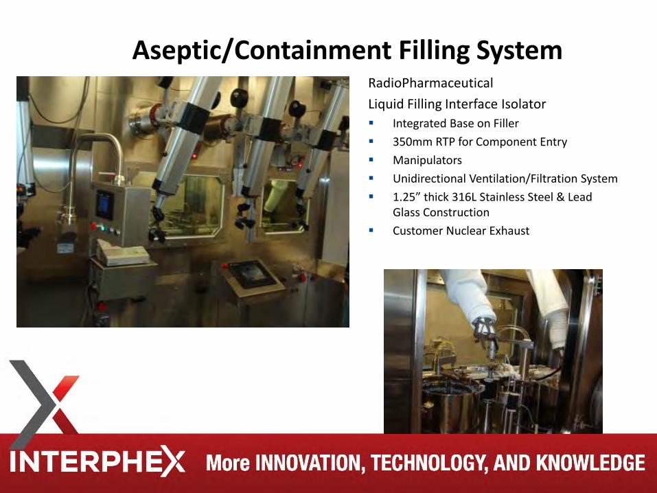
RadioPharmaceutical Liquid Filling Interface Isolator Integrated Base on Filler 350mm RTP for Component Entry Manipulators Unidirectional Ventilation/Filtration System 1.25” thick 316L Stainless Steel & Lead
Glass Construction Customer Nuclear Exhaust
Aseptic/Containment Filling System
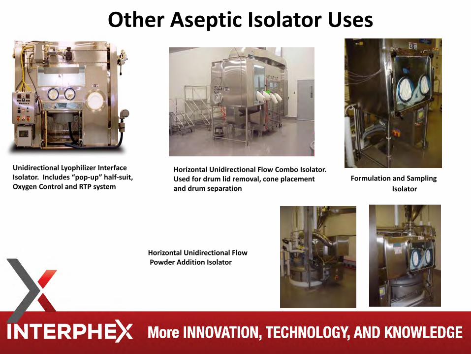
Horizontal Unidirectional Flow Combo Isolator. Used for drum lid removal, cone placement and drum separation
Unidirectional Lyophilizer Interface Isolator. Includes “pop-up” half-suit, Oxygen Control and RTP system
Formulation and Sampling Isolator
Horizontal Unidirectional Flow Powder Addition Isolator
Other Aseptic Isolator Uses
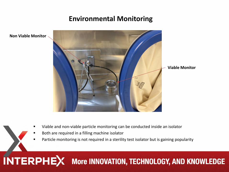
Environmental Monitoring
Viable and non-viable particle monitoring can be conducted inside an isolator Both are required in a filling machine isolator Particle monitoring is not required in a sterility test isolator but is gaining popularity
Viable Monitor
Non Viable Monitor
Restricted Access Barrier (RABs) were developed to enhance aseptic process carried out in conventional clean rooms. As defined by the ISPE in 2005, a RAB system is to include: • Rigid wall enclosure • ISO 5 UAF environment • Gloves for set up and interventions • Automation of the process wherever possible • High level disinfection • Rare open door interventions
RABs qualification will be similar to a clean room and includes: • Air exchange rates • Airflow velocity • Pressure differential • Smoke tests • Environmental monitoring
Restricted Access Barrier – RABs
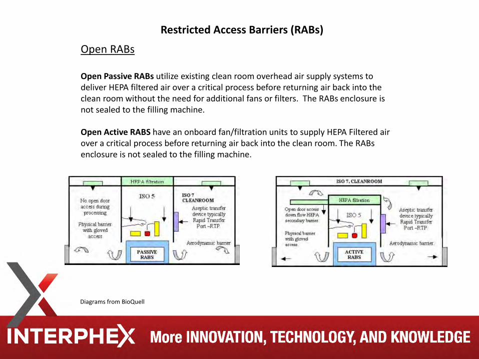
Open RABs Open Passive RABs utilize existing clean room overhead air supply systems to deliver HEPA filtered air over a critical process before returning air back into the clean room without the need for additional fans or filters. The RABs enclosure is not sealed to the filling machine. Open Active RABS have an onboard fan/filtration units to supply HEPA Filtered air over a critical process before returning air back into the clean room. The RABs enclosure is not sealed to the filling machine.
Restricted Access Barriers (RABs)
Diagrams from BioQuell
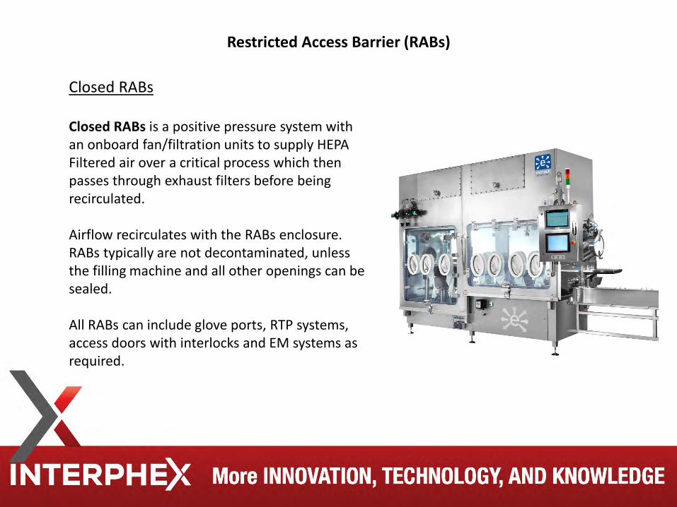
Restricted Access Barrier (RABs)
Closed RABs Closed RABs is a positive pressure system with an onboard fan/filtration units to supply HEPA Filtered air over a critical process which then passes through exhaust filters before being recirculated. Airflow recirculates with the RABs enclosure. RABs typically are not decontaminated, unless the filling machine and all other openings can be sealed. All RABs can include glove ports, RTP systems, access doors with interlocks and EM systems as required.
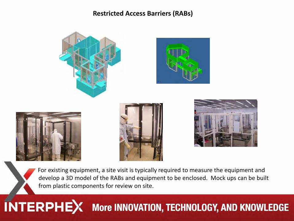
For existing equipment, a site visit is typically required to measure the equipment and develop a 3D model of the RABs and equipment to be enclosed. Mock ups can be built from plastic components for review on site.
Restricted Access Barriers (RABs)
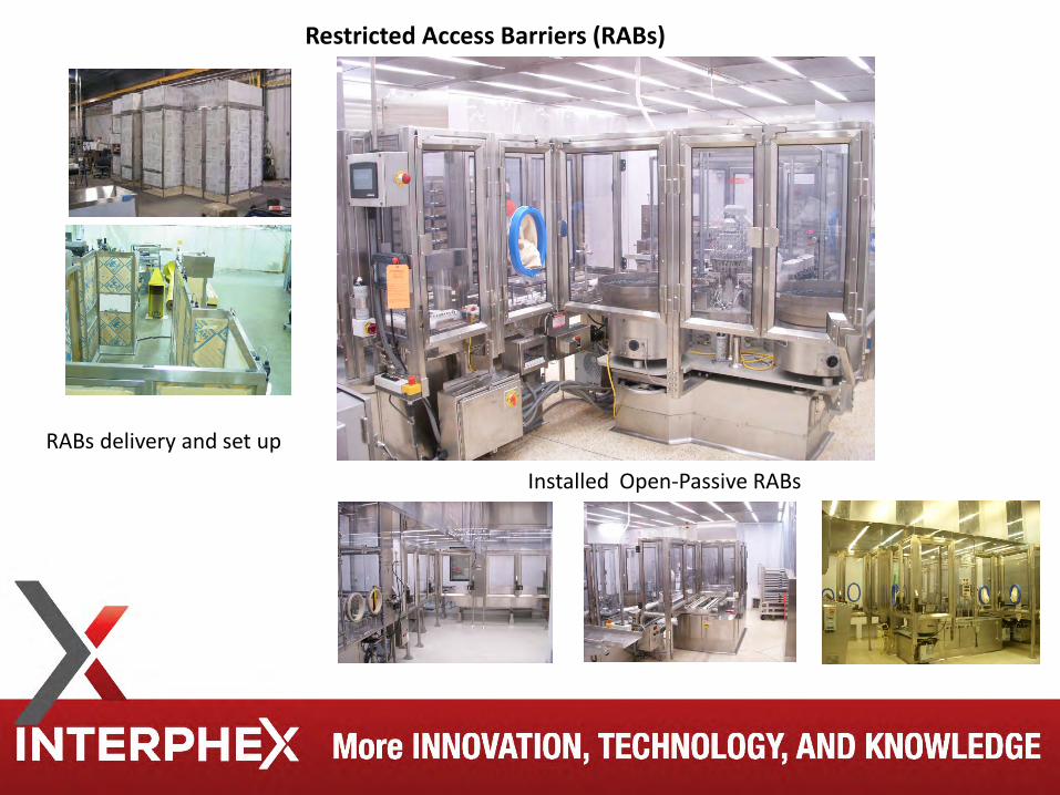
RABs delivery and set up
Installed Open-Passive RABs
Restricted Access Barriers (RABs)
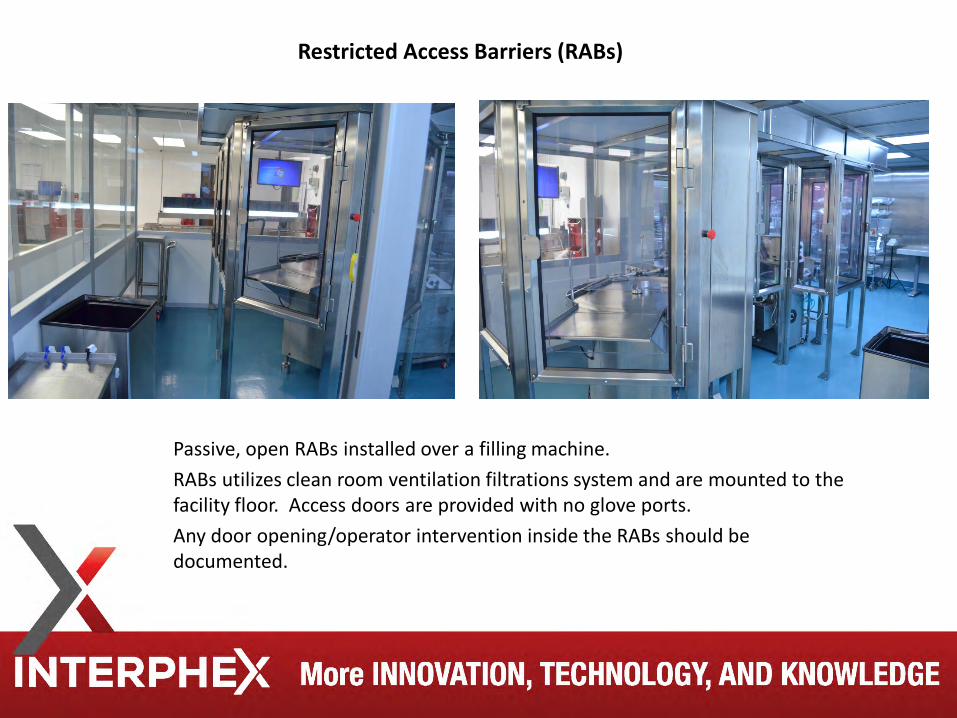
Passive, open RABs installed over a filling machine. RABs utilizes clean room ventilation filtrations system and are mounted to the
facility floor. Access doors are provided with no glove ports. Any door opening/operator intervention inside the RABs should be
documented.
Restricted Access Barriers (RABs)
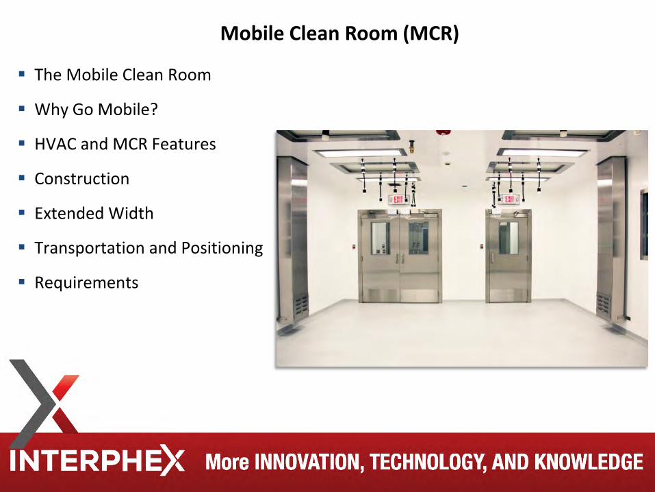
The Mobile Clean Room
Why Go Mobile?
HVAC and MCR Features
Construction
Extended Width
Transportation and Positioning
Requirements
Mobile Clean Room (MCR)
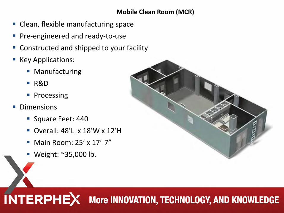
Clean, flexible manufacturing space Pre-engineered and ready-to-use Constructed and shipped to your facility Key Applications:
Manufacturing R&D Processing
Dimensions Square Feet: 440 Overall: 48’L x 18’W x 12’H Main Room: 25’ x 17’-7” Weight: ~35,000 lb.
Mobile Clean Room (MCR)
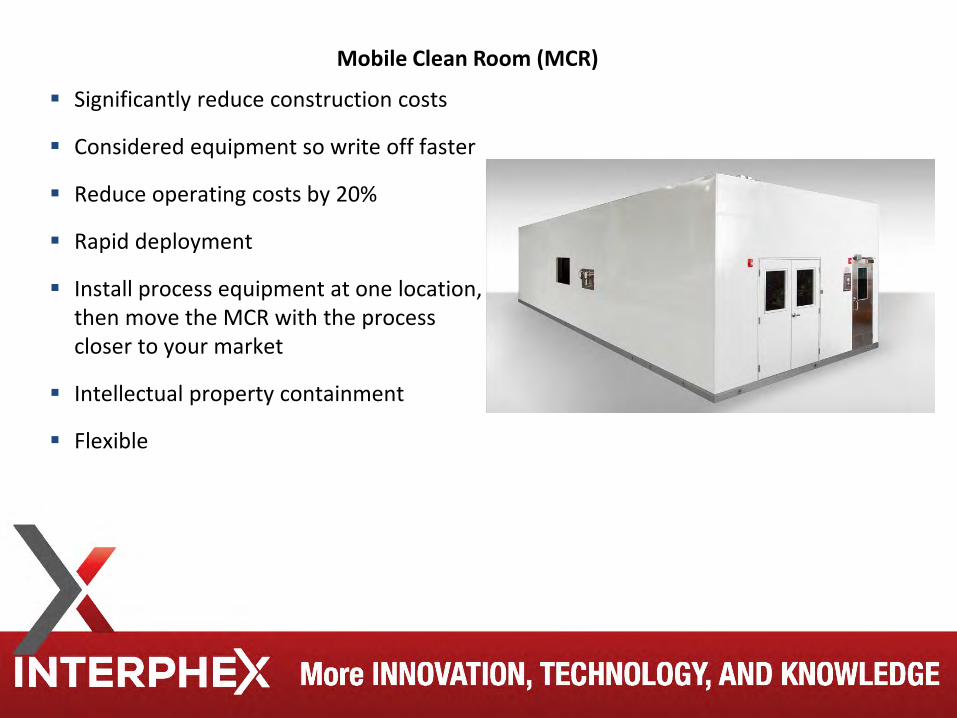
Significantly reduce construction costs
Considered equipment so write off faster
Reduce operating costs by 20%
Rapid deployment
Install process equipment at one location, then move the MCR with the process closer to your market
Intellectual property containment
Flexible
Mobile Clean Room (MCR)
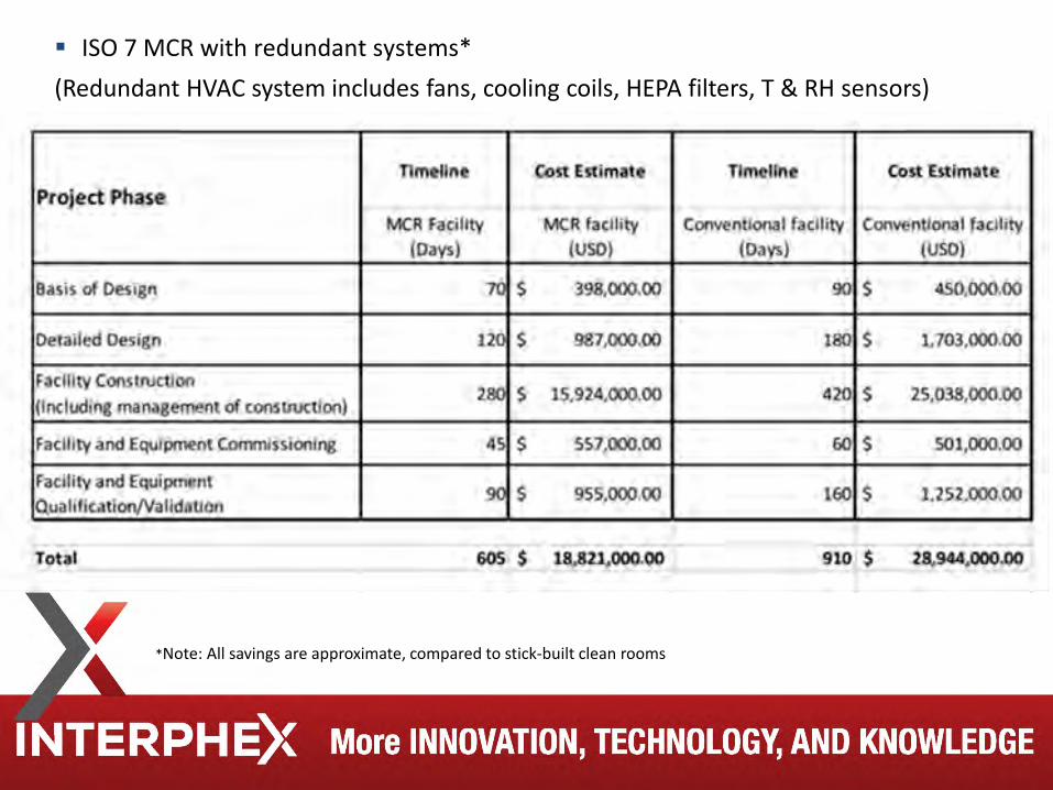
ISO 7 MCR with redundant systems* (Redundant HVAC system includes fans, cooling coils, HEPA filters, T & RH sensors)
*Note: All savings are approximate, compared to stick-built clean rooms
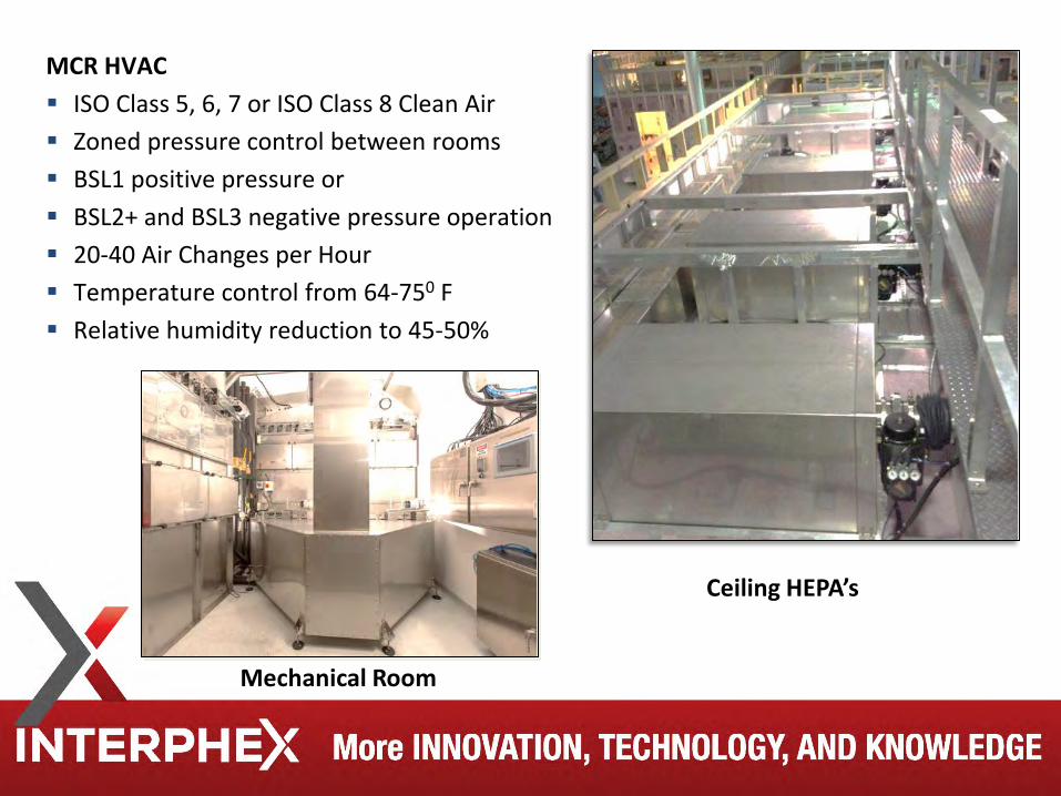
MCR HVAC ISO Class 5, 6, 7 or ISO Class 8 Clean Air Zoned pressure control between rooms BSL1 positive pressure or BSL2+ and BSL3 negative pressure operation 20-40 Air Changes per Hour Temperature control from 64-750 F Relative humidity reduction to 45-50%
Mechanical Room
Ceiling HEPA’s
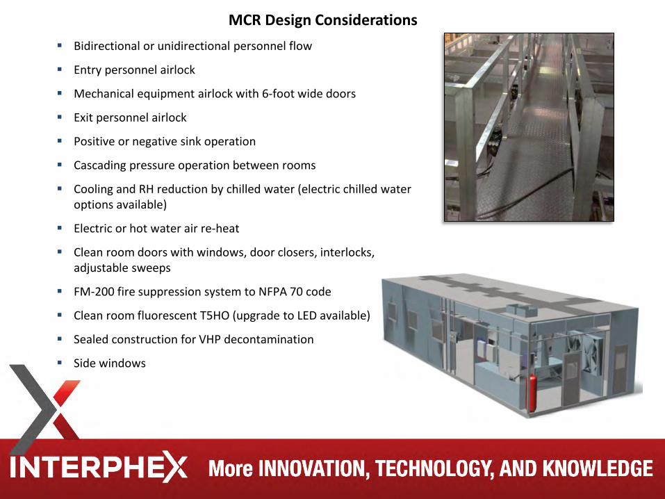
Bidirectional or unidirectional personnel flow
Entry personnel airlock
Mechanical equipment airlock with 6-foot wide doors
Exit personnel airlock
Positive or negative sink operation
Cascading pressure operation between rooms
Cooling and RH reduction by chilled water (electric chilled water options available)
Electric or hot water air re-heat
Clean room doors with windows, door closers, interlocks, adjustable sweeps
FM-200 fire suppression system to NFPA 70 code
Clean room fluorescent T5HO (upgrade to LED available)
Sealed construction for VHP decontamination
Side windows
MCR Design Considerations
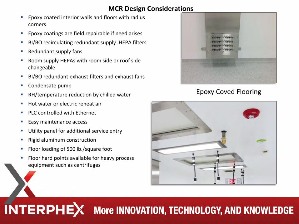
Epoxy coated interior walls and floors with radius corners
Epoxy coatings are field repairable if need arises BI/BO recirculating redundant supply HEPA filters Redundant supply fans Room supply HEPAs with room side or roof side
changeable BI/BO redundant exhaust filters and exhaust fans Condensate pump RH/temperature reduction by chilled water Hot water or electric reheat air PLC controlled with Ethernet Easy maintenance access Utility panel for additional service entry Rigid aluminum construction Floor loading of 500 lb./square foot Floor hard points available for heavy process
equipment such as centrifuges
Epoxy Coved Flooring
MCR Design Considerations
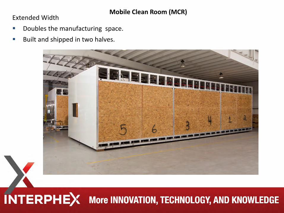
Extended Width Doubles the manufacturing space. Built and shipped in two halves.
Mobile Clean Room (MCR)
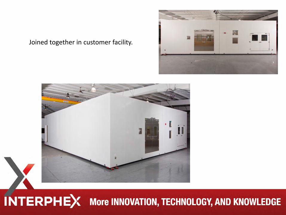
Joined together in customer facility.
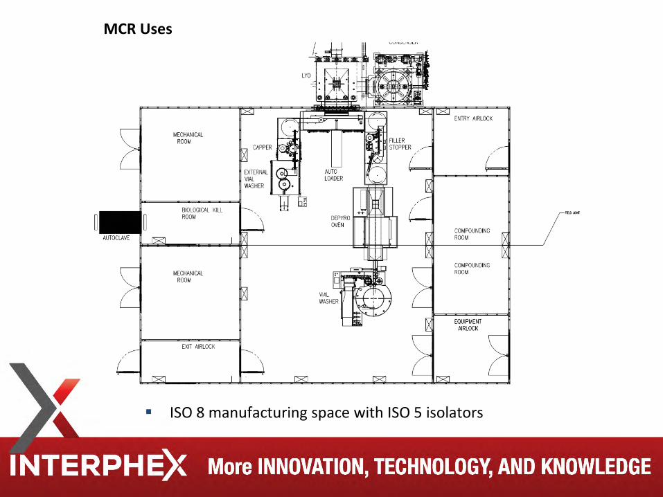
ISO 8 manufacturing space with ISO 5 isolators
MCR Uses
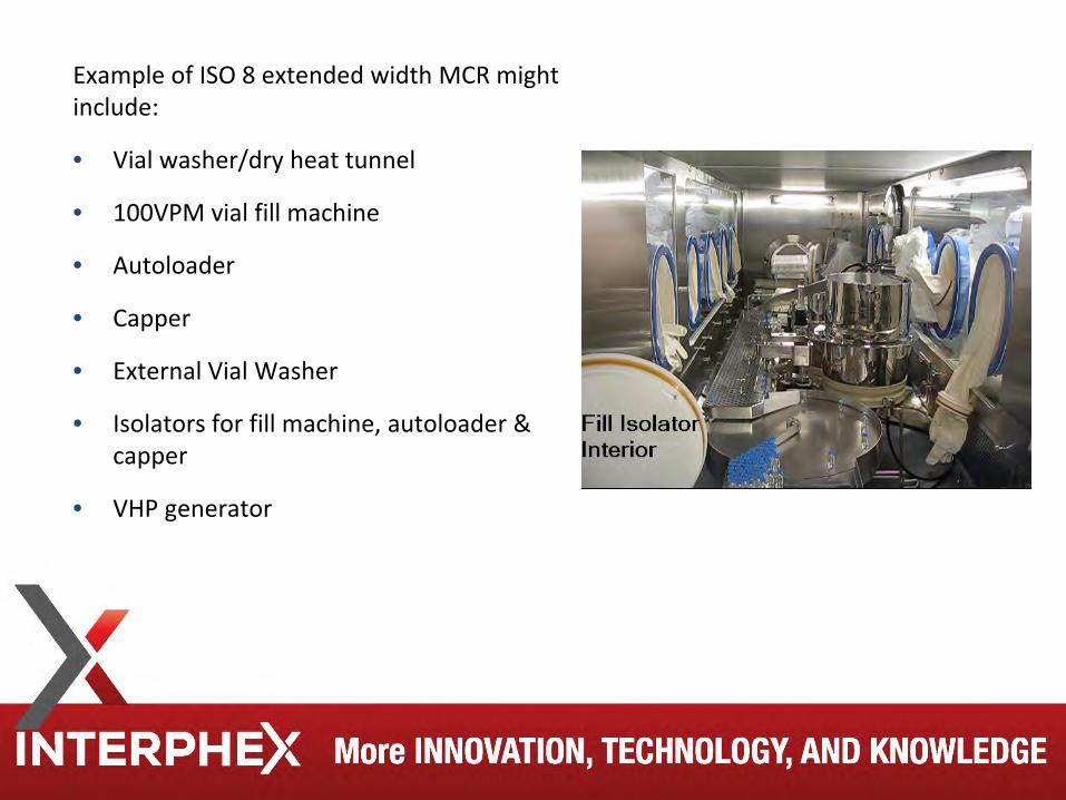
Example of ISO 8 extended width MCR might include:
• Vial washer/dry heat tunnel
• 100VPM vial fill machine
• Autoloader
• Capper
• External Vial Washer
• Isolators for fill machine, autoloader & capper
• VHP generator
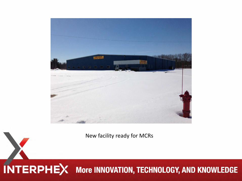
New facility ready for MCRs
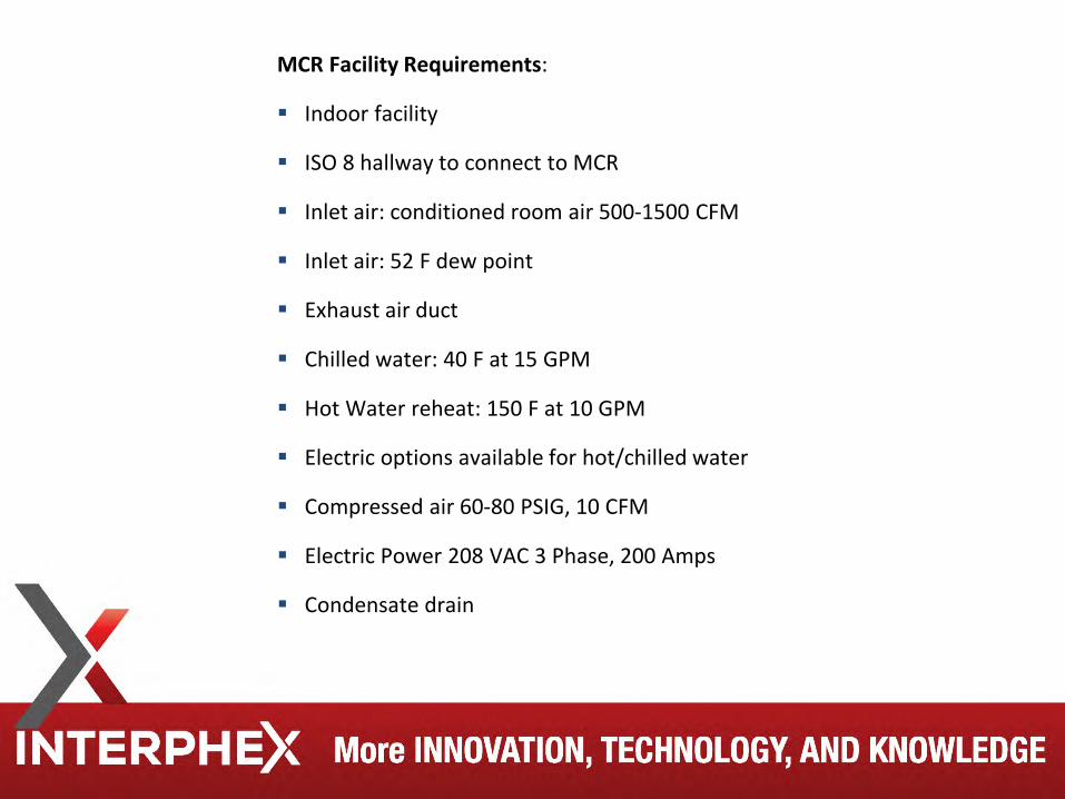
MCR Facility Requirements:
Indoor facility
ISO 8 hallway to connect to MCR
Inlet air: conditioned room air 500-1500 CFM
Inlet air: 52 F dew point
Exhaust air duct
Chilled water: 40 F at 15 GPM
Hot Water reheat: 150 F at 10 GPM
Electric options available for hot/chilled water
Compressed air 60-80 PSIG, 10 CFM
Electric Power 208 VAC 3 Phase, 200 Amps
Condensate drain
Thank You