isoria 16 - ksb€¦ · butterfly valves centred-disc butterfly valves isoria 16 main applications...
TRANSCRIPT
Butterfly Valve
ISORIA 16
Centred-disc Butterfly ValveAMRING Elastomer LinerDN 40-1000PS 16 bar
Type Series Booklet

Legal information/Copyright
Type Series Booklet ISORIA 16
All rights reserved. The contents provided herein must neither be distributed, copied, reproduced,edited or processed for any other purpose, nor otherwise transmitted, published or made available toa third party without the manufacturer's express written consent.
Subject to technical modification without prior notice.
© KSB S.A.S, Gennevilliers (Paris), France 21.07.2014
Butterfly Valves
Centred-disc Butterfly Valves
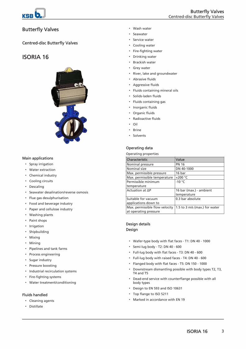
ISORIA 16
Main applications
▪ Spray irrigation
▪ Water extraction
▪ Chemical industry
▪ Cooling circuits
▪ Descaling
▪ Seawater desalination/reverse osmosis
▪ Flue gas desulphurisation
▪ Food and beverage industry
▪ Paper and cellulose industry
▪ Washing plants
▪ Paint shops
▪ Irrigation
▪ Shipbuilding
▪ Mixing
▪ Mining
▪ Pipelines and tank farms
▪ Process engineering
▪ Sugar industry
▪ Pressure boosting
▪ Industrial recirculation systems
▪ Fire-fighting systems
▪ Water treatment/conditioning
Fluids handled
▪ Cleaning agents
▪ Distillate
▪ Wash water
▪ Seawater
▪ Service water
▪ Cooling water
▪ Fire-fighting water
▪ Drinking water
▪ Brackish water
▪ Grey water
▪ River, lake and groundwater
▪ Abrasive fluids
▪ Aggressive fluids
▪ Fluids containing mineral oils
▪ Solids-laden fluids
▪ Fluids containing gas
▪ Inorganic fluids
▪ Organic fluids
▪ Radioactive fluids
▪ Oil
▪ Brine
▪ Solvents
Operating data
Operating properties
Characteristic ValueNominal pressure PN 16Nominal size DN 40-1000Max. permissible pressure 16 barMax. permissible temperature +200 °CPermissible minimumtemperature
-10 °C
Actuation at ΔP 16 bar (max.) - ambienttemperature
Suitable for vacuumapplications down to
0.3 bar absolute
Max. permissible flow velocityat operating pressure
1.5 to 3 m/s (max.) for water
Design details
Design
▪ Wafer-type body with flat faces - T1: DN 40 - 1000
▪ Semi-lug body - T2: DN 40 - 600
▪ Full-lug body with flat faces - T3: DN 40 - 600
▪ Full-lug body with raised faces - T4: DN 40 - 600
▪ Flanged body with flat faces - T5: DN 150 - 1000
▪ Downstream dismantling possible with body types T2, T3,T4 and T5
▪ Dead-end service with counterflange possible with allbody types
▪ Design to EN 593 and ISO 10631
▪ Top flange to ISO 5211
▪ Marked in accordance with EN 19
Butterfly ValvesCentred-disc Butterfly Valves
ISORIA 16 3
▪ Absolutely tight shut-off (no leakage visible to the nakedeye) in either direction of flow in accordance with EN12266-1, leakage rate A, and ISO 5208, category A.
▪ Face-to-face length to ISO 5752-20 and EN 558-1-20
▪ EN, ASME, JIS, AWWA connections possible.
▪ Body with polyurethane coating, thickness 80 µm, colour:RAL 5002, blue.
▪ Valve disc made of nodular cast iron, epoxy-coated,thickness 80 μm, colour: RAL 8012, brown
▪ The valves satisfy the safety requirements of Annex I ofthe European Pressure Equipment Directive 97/23/EC (PED)for fluids in Groups 1 and 2.
▪ Valves with actuators can meet the requirements of the2006/42/EC Machinery Directive for partly completedmachinery.
▪ The valves meet the requirements of the REACH 1907/2006regulation. None of the substances listed in the candidatelist and in Annex XIV of the regulation is present in aconcentration above 0.1 % (w/w) (Article 33/REACH).
Variants
▪ Valve cleaned and packaged, free from substances whichimpair the adhesive strength of paint
▪ S / SR / SP quarter-turn levers
▪ MN / MR manual gearboxes
▪ ACTELEC electric actuators
▪ ACTAIR / DYNACTAIR pneumatic actuators
▪ ACTO/DYNACTO/ENNACTO hydraulic actuators
▪ AMTROBOX control unit for position indication
▪ AMTRONIC valve controller with compressed air supply viadirectional control valve
▪ SMARTRONIC intelligent positioner
▪ ATEX design in compliance with the 94/9/EC Directive
Body materials
Overview of available materials
Material Materialnumber
Body DN (max.) KSBcode
EN-GJL-250 JL 1040 T1 DN 40-600 3tEN-JS1030
ASTM A536gr. 60.40.18
JS 1030 DN 650-1000 3g
EN-JS1030 JS 1030 T2 DN 40-600 3gASTM A 216gr. CCC
T3 DN 40-600 1
EN-JS1030 JS 1030 T4 DN 40-600 3gEN-JS1030 JS 1030 T5 DN 150-600 3gEN-JS1030
ASTM A536gr. 60.40.18
JS 1030 DN 650-1000
Product benefits
▪ Spherically machined valve disc with rounded sealingcontour
– ensures durable and permanently tight shut-off
▪ Splined or keyed connection between stem and valve disc
– Dry stem, no contact with fluid handled
▪ Sealing to atmosphere and tight shut-off are ensured,
– even when the actuator has been removed
▪ Marking indicates position of valve disc
▪ Stem in anti-blow-out design
– Stem is retained in the body.
▪ Valve equipped with stainless steel bearings withreinforced PTFE coating
▪ The elastomer liner provides tight sealing at the flangedline connections, eliminating the need for a flange gasket.
▪ Valve certified to
– ACS / DVGW / WRAS for drinking water applications,with elastomer liner, KSB code XC
▪ Elastomer liner
– EPDM - XC approved by KTW, ILP Nancy, WRC
▪ Valve actuation options:
– Manual
– Electric
– Pneumatic
– Hydraulic
Related documents
Other applicable documents
Document Reference No.Actuator selection 8445.11Operating manual 8449.8
On all enquiries / orders please specify
1. Type series
2. Nominal pressure
3. Nominal size
4. Fluid handled
5. Flow rate/velocity
6. Temperature
7. Materials (body, valve disc, seat)
8. Line connection, flange facing and flange surface quality
9. Actuator/automation
10. Reference number of type series booklet
Butterfly ValvesCentred-disc Butterfly Valves
4 ISORIA 16
Technical data
Pressure limits of AMRING liners
DN NPS Max. permissible pressure PS [bar]
XA - XC - XV - K Z40-600 1½-24 16 16650-1000 26-40 16 -
Vacuum resistance
DN NPS Liner mounting method Minimum pressure Max. temperature
[bar absolute] XV Other40-300 1½-12 Non-glued (standard) 1,33 . 10 -5 (10-2torr) 130 °C 80 °C350-1000 14-40 Non-glued (standard) 0,3 130 °C 80 °C350-1000 14-40 Glued (optional) 1,33 . 10 -5 (10-2torr) 80 °C 80 °C
Hydraulic characteristics
DN NPS Flow coefficient with disc fully open Zeta
Kvo Cvo
40 1½ 53 62 1,4650 2 133 154 0,5665 2½ 240 280 0,4980 3 410 475 0,39100 4 655 760 0,37125 5 900 1044 0,48150 6 1800 2090 0,25200 8 3550 4120 0,20250 10 7350 8453 0,12300 12 9100 10465 0,16350 14 8060 9269 0,37400 16 10500 12075 0,37450 18 13300 15295 0,37500 20 17400 20010 0,33550 22 21000 24150 0,33600 24 25000 28750 0,33650 26 37700 43730 0,20700 28 47500 55100 0,17750 30 51500 59740 0,19800 32 63500 73660 0,16900 36 84700 98250 0,151000 40 108500 125860 0,14
Butterfly ValvesCentred-disc Butterfly Valves
ISORIA 16 5
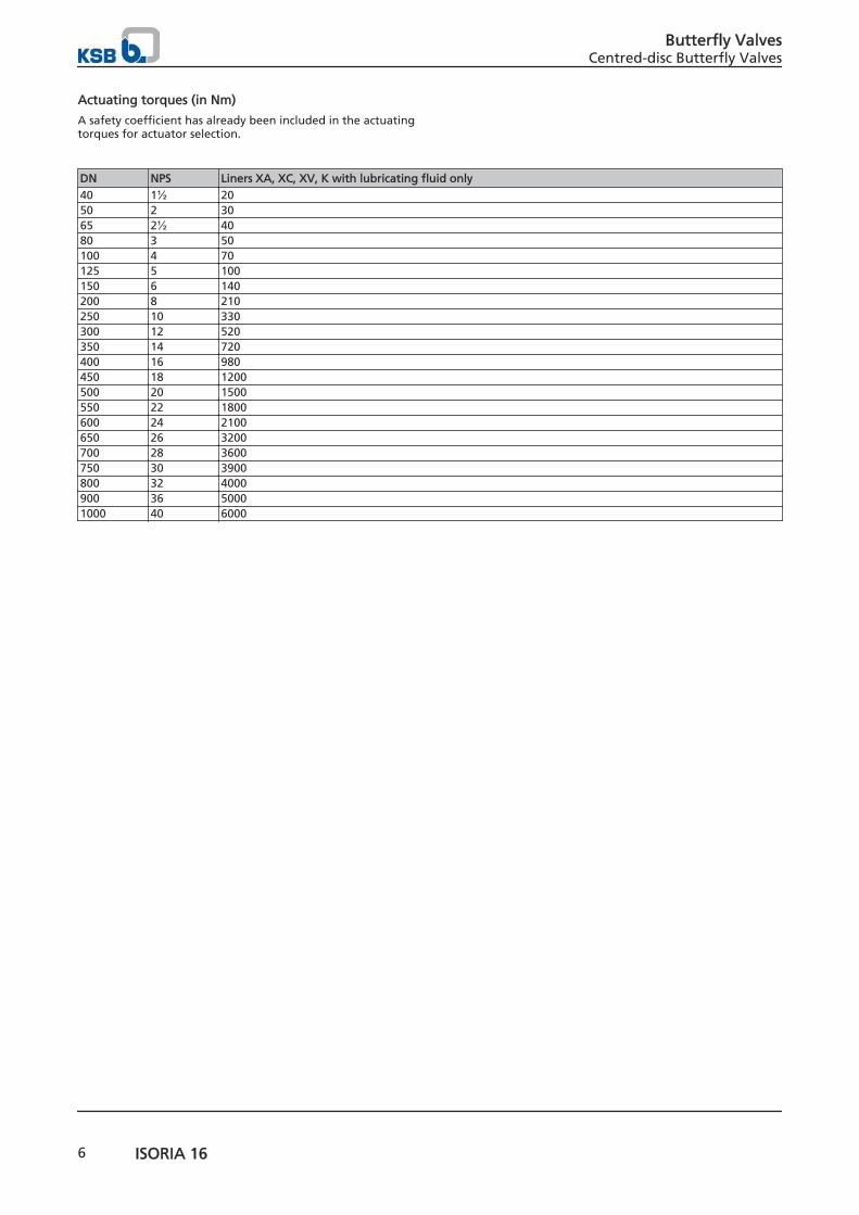
Actuating torques (in Nm)
A safety coefficient has already been included in the actuatingtorques for actuator selection.
DN NPS Liners XA, XC, XV, K with lubricating fluid only40 1½ 2050 2 3065 2½ 4080 3 50100 4 70125 5 100150 6 140200 8 210250 10 330300 12 520350 14 720400 16 980450 18 1200500 20 1500550 22 1800600 24 2100650 26 3200700 28 3600750 30 3900800 32 4000900 36 50001000 40 6000
Butterfly ValvesCentred-disc Butterfly Valves
6 ISORIA 16
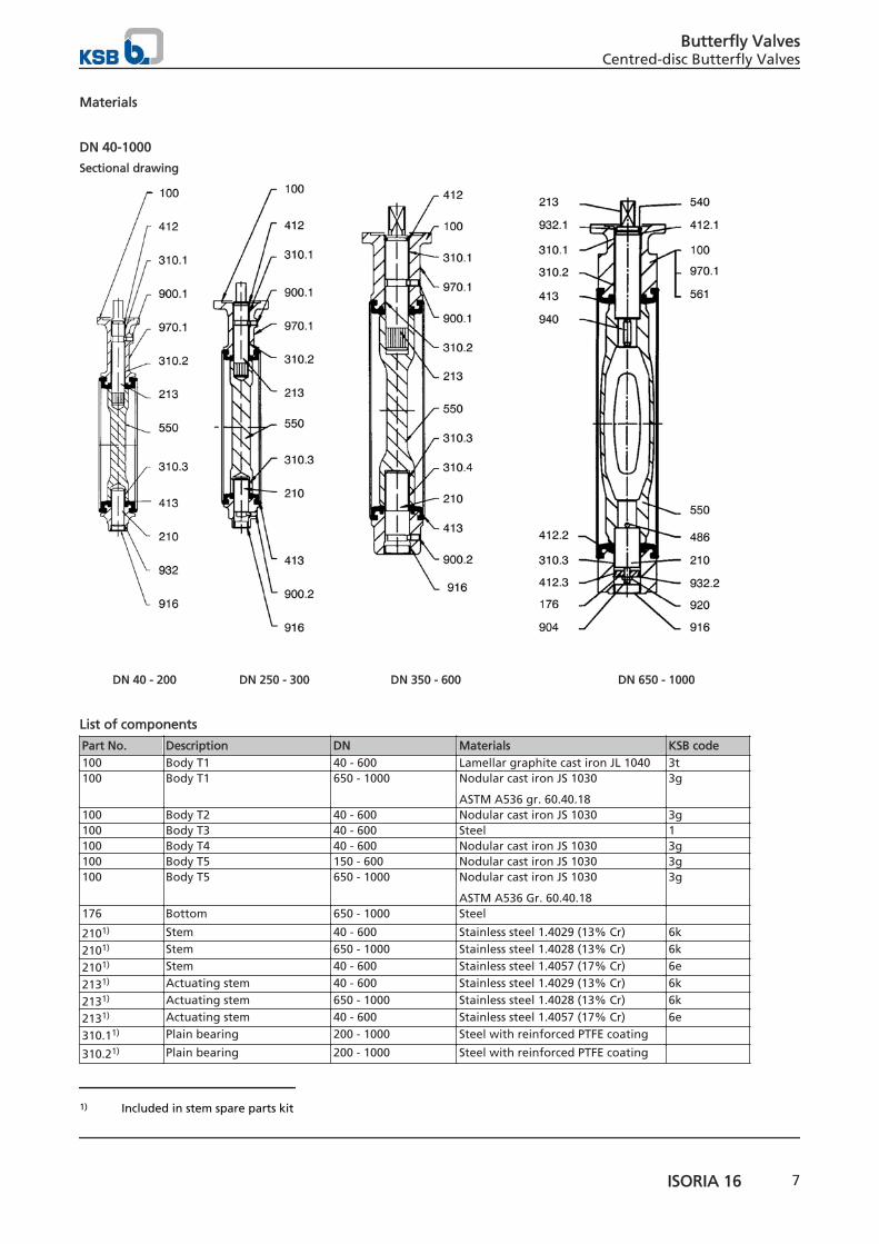
Materials
DN 40-1000
Sectional drawing
DN 40 - 200 DN 250 - 300 DN 350 - 600 DN 650 - 1000
List of components
Part No. Description DN Materials KSB code100 Body T1 40 - 600 Lamellar graphite cast iron JL 1040 3t100 Body T1 650 - 1000 Nodular cast iron JS 1030
ASTM A536 gr. 60.40.18
3g
100 Body T2 40 - 600 Nodular cast iron JS 1030 3g100 Body T3 40 - 600 Steel 1100 Body T4 40 - 600 Nodular cast iron JS 1030 3g100 Body T5 150 - 600 Nodular cast iron JS 1030 3g100 Body T5 650 - 1000 Nodular cast iron JS 1030
ASTM A536 Gr. 60.40.18
3g
176 Bottom 650 - 1000 Steel 2101) Stem 40 - 600 Stainless steel 1.4029 (13% Cr) 6k
2101) Stem 650 - 1000 Stainless steel 1.4028 (13% Cr) 6k
2101) Stem 40 - 600 Stainless steel 1.4057 (17% Cr) 6e
2131) Actuating stem 40 - 600 Stainless steel 1.4029 (13% Cr) 6k
2131) Actuating stem 650 - 1000 Stainless steel 1.4028 (13% Cr) 6k
2131) Actuating stem 40 - 600 Stainless steel 1.4057 (17% Cr) 6e
310.11) Plain bearing 200 - 1000 Steel with reinforced PTFE coating 310.21) Plain bearing 200 - 1000 Steel with reinforced PTFE coating
1) Included in stem spare parts kit
Butterfly ValvesCentred-disc Butterfly Valves
ISORIA 16 7
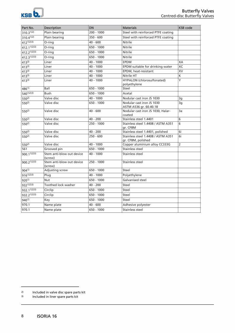
Part No. Description DN Materials KSB code
310.31)2) Plain bearing 200 - 1000 Steel with reinforced PTFE coating 310.41)2) Plain bearing 350 - 600 Steel with reinforced PTFE coating 4121)2)3) O-ring 40 - 600 Nitrile 412.11)2)3) O-ring 650 - 1000 Nitrile 412.21)2)3) O-ring 650 - 1000 Nitrile 412.31)2)3) O-ring 650 - 1000 Nitrile 4133) Liner 40 - 1000 EPDM XA
4133) Liner 40 - 1000 EPDM suitable for drinking water XC
4133) Liner 40 - 1000 EPDM, heat-resistant XV
4133) Liner 40 - 1000 Nitrile HT K
4133) Liner 40 - 1000 HYPALON (chlorosulfonated)polyethylene
Y
4861) Ball 650 - 1000 Steel 5401)2)3) Bush 650 - 1000 Acetal 5502) Valve disc 40 - 1000 Nodular cast iron JS 1030 3g
5502) Valve disc 650 - 1000 Nodular cast iron JS 1030ASTM A536 gr. 60.40.18
3g
5502) Valve disc 40 - 600 Nodular cast iron JS 1030, Halar-coated
3a
5502) Valve disc 40 - 200 Stainless steel 1.4401 6
5502) Valve disc 250 - 1000 Stainless steel 1.4408 / ASTM A351gr. CF8M
6
5502) Valve disc 40 - 200 Stainless steel 1.4401, polished 6i
5502) Valve disc 250 - 600 Stainless steel 1.4408 / ASTM A351gr. CF8M, polished
6i
5502) Valve disc 40 - 1000 Copper aluminium alloy CC333G 2561 Grooved pin 650 - 1000 Stainless steel 900.11)2)3) Stem anti-blow out device
(screw)40 - 1000 Stainless steel
900.21)2)3) Stem anti-blow out device(screw)
250 - 1000 Stainless steel
9041) Adjusting screw 650 - 1000 Steel 9161)2)3) Plug 40 - 1000 Polyethylene 9201) Nut 650 - 1000 Galvanised steel 9321)2)3) Toothed lock washer 40 - 200 Steel 932.11)2)3) Circlip 650 - 1000 Steel 932.21)2)3) Circlip 650 - 1000 Steel 9401) Key 650 - 1000 Steel 970.1 Name plate 40 - 600 Adhesive polyester 970.1 Name plate 650 - 1000 Stainless steel
2) Included in valve disc spare parts kit3) Included in liner spare parts kit
Butterfly ValvesCentred-disc Butterfly Valves
8 ISORIA 16
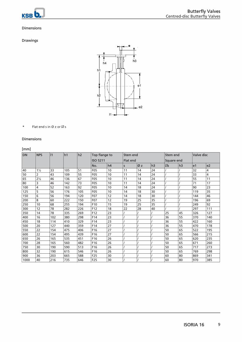
Dimensions
Drawings
* Flat end s in Ø z or s
Dimensions
[mm]
DN NPS l1 h1 h2 Top flange to
ISO 5211
Stem end
Flat end
Stem end
Square end
Valve disc
No. h4 s Ø z h3 s h3 e1 e240 1½ 33 105 51 F05 10 11 14 24 / / 32 450 2 43 109 55 F05 10 11 14 24 / / 33 465 2½ 46 136 67 F05 10 11 14 24 / / 55 1180 3 46 142 73 F05 10 11 14 24 / / 71 17100 4 52 163 92 F05 10 14 18 24 / / 90 23125 5 56 176 105 F05 10 14 18 30 / / 119 35150 6 56 194 120 F07 12 14 18 30 / / 144 46200 8 60 222 150 F07 12 19 25 35 / / 196 69250 10 68 255 194 F10 15 19 25 35 / / 249 92300 12 78 282 226 F12 18 22 28 40 / / 297 111350 14 78 335 269 F12 23 / / / 25 45 326 127400 16 102 380 298 F14 23 / / / 36 55 370 140450 18 114 410 329 F14 23 / / / 36 55 422 160500 20 127 440 359 F14 27 / / / 36 55 470 178550 22 154 475 406 F16 27 / / / 50 65 522 195600 22 154 495 439 F16 27 / / / 50 65 566 215650 26 165 535 451 F16 26 / / / 50 65 620 235700 28 165 560 482 F16 26 / / / 50 65 671 260750 30 190 590 513 F16 26 / / / 50 65 717 273800 32 190 615 546 F16 26 / / / 50 65 769 298900 36 203 665 588 F25 30 / / / 60 80 869 3411000 40 216 735 646 F25 30 / / / 60 80 970 385
Butterfly ValvesCentred-disc Butterfly Valves
ISORIA 16 9
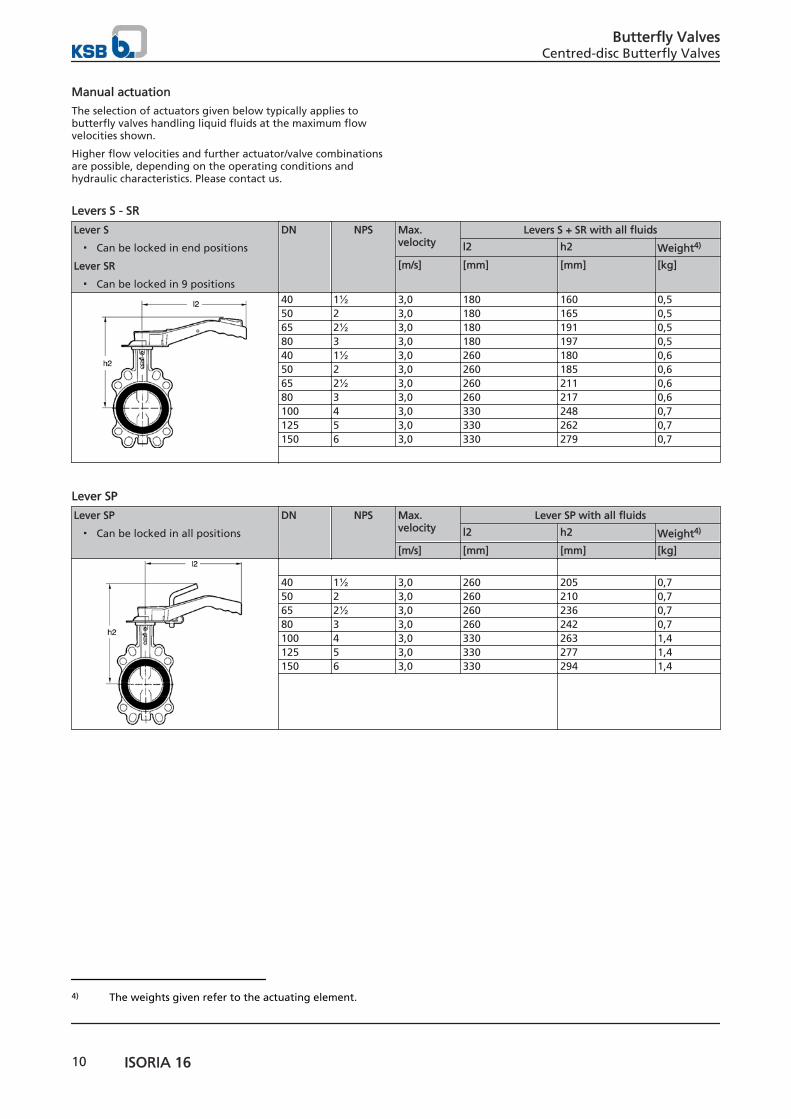
Manual actuation
The selection of actuators given below typically applies tobutterfly valves handling liquid fluids at the maximum flowvelocities shown.
Higher flow velocities and further actuator/valve combinationsare possible, depending on the operating conditions andhydraulic characteristics. Please contact us.
Levers S - SR
Lever S
▪ Can be locked in end positions
Lever SR
▪ Can be locked in 9 positions
DN NPS Max.velocity
Levers S + SR with all fluids
l2 h2 Weight4)
[m/s] [mm] [mm] [kg]
40 1½ 3,0 180 160 0,550 2 3,0 180 165 0,565 2½ 3,0 180 191 0,580 3 3,0 180 197 0,540 1½ 3,0 260 180 0,650 2 3,0 260 185 0,665 2½ 3,0 260 211 0,680 3 3,0 260 217 0,6100 4 3,0 330 248 0,7125 5 3,0 330 262 0,7150 6 3,0 330 279 0,7
Lever SP
Lever SP
▪ Can be locked in all positions
DN NPS Max.velocity
Lever SP with all fluids
l2 h2 Weight4)
[m/s] [mm] [mm] [kg]
40 1½ 3,0 260 205 0,750 2 3,0 260 210 0,765 2½ 3,0 260 236 0,780 3 3,0 260 242 0,7100 4 3,0 330 263 1,4125 5 3,0 330 277 1,4150 6 3,0 330 294 1,4
4) The weights given refer to the actuating element.
Butterfly ValvesCentred-disc Butterfly Valves
10 ISORIA 16
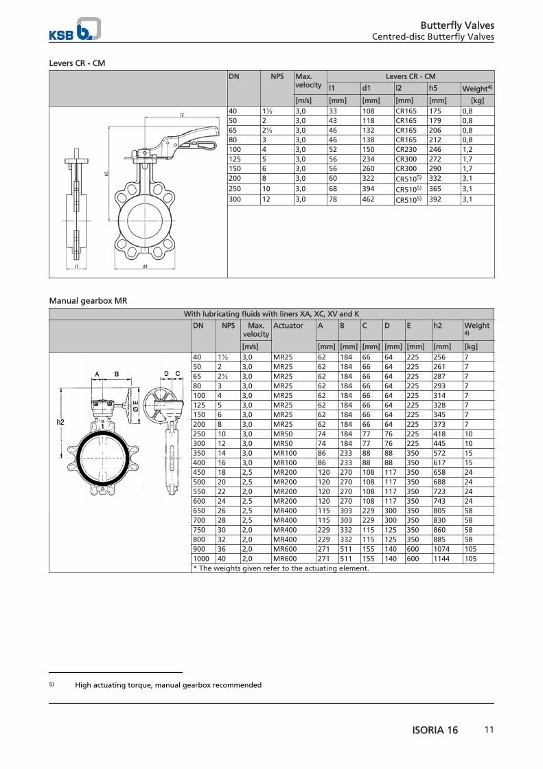
Levers CR - CM
DN NPS Max.velocity
Levers CR - CM
l1 d1 l2 h5 Weight4)
[m/s] [mm] [mm] [mm] [mm] [kg]40 1½ 3,0 33 108 CR165 175 0,850 2 3,0 43 118 CR165 179 0,865 2½ 3,0 46 132 CR165 206 0,880 3 3,0 46 138 CR165 212 0,8100 4 3,0 52 150 CR230 246 1,2125 5 3,0 56 234 CR300 272 1,7150 6 3,0 56 260 CR300 290 1,7200 8 3,0 60 322 CR5105) 332 3,1250 10 3,0 68 394 CR5105) 365 3,1300 12 3,0 78 462 CR5105) 392 3,1
Manual gearbox MR
With lubricating fluids with liners XA, XC, XV and K
DN NPS Max.velocity
Actuator A B C D E h2 Weight4)
[m/s] [mm] [mm] [mm] [mm] [mm] [mm] [kg]40 1½ 3,0 MR25 62 184 66 64 225 256 750 2 3,0 MR25 62 184 66 64 225 261 765 2½ 3,0 MR25 62 184 66 64 225 287 780 3 3,0 MR25 62 184 66 64 225 293 7100 4 3,0 MR25 62 184 66 64 225 314 7125 5 3,0 MR25 62 184 66 64 225 328 7150 6 3,0 MR25 62 184 66 64 225 345 7200 8 3,0 MR25 62 184 66 64 225 373 7250 10 3,0 MR50 74 184 77 76 225 418 10300 12 3,0 MR50 74 184 77 76 225 445 10350 14 3,0 MR100 86 233 88 88 350 572 15400 16 3,0 MR100 86 233 88 88 350 617 15450 18 2,5 MR200 120 270 108 117 350 658 24500 20 2,5 MR200 120 270 108 117 350 688 24550 22 2,0 MR200 120 270 108 117 350 723 24600 24 2,5 MR200 120 270 108 117 350 743 24650 26 2,5 MR400 115 303 229 300 350 805 58700 28 2,5 MR400 115 303 229 300 350 830 58750 30 2,0 MR400 229 332 115 125 350 860 58800 32 2,0 MR400 229 332 115 125 350 885 58900 36 2,0 MR600 271 511 155 140 600 1074 1051000 40 2,0 MR600 271 511 155 140 600 1144 105* The weights given refer to the actuating element.
5) High actuating torque, manual gearbox recommended
Butterfly ValvesCentred-disc Butterfly Valves
ISORIA 16 11
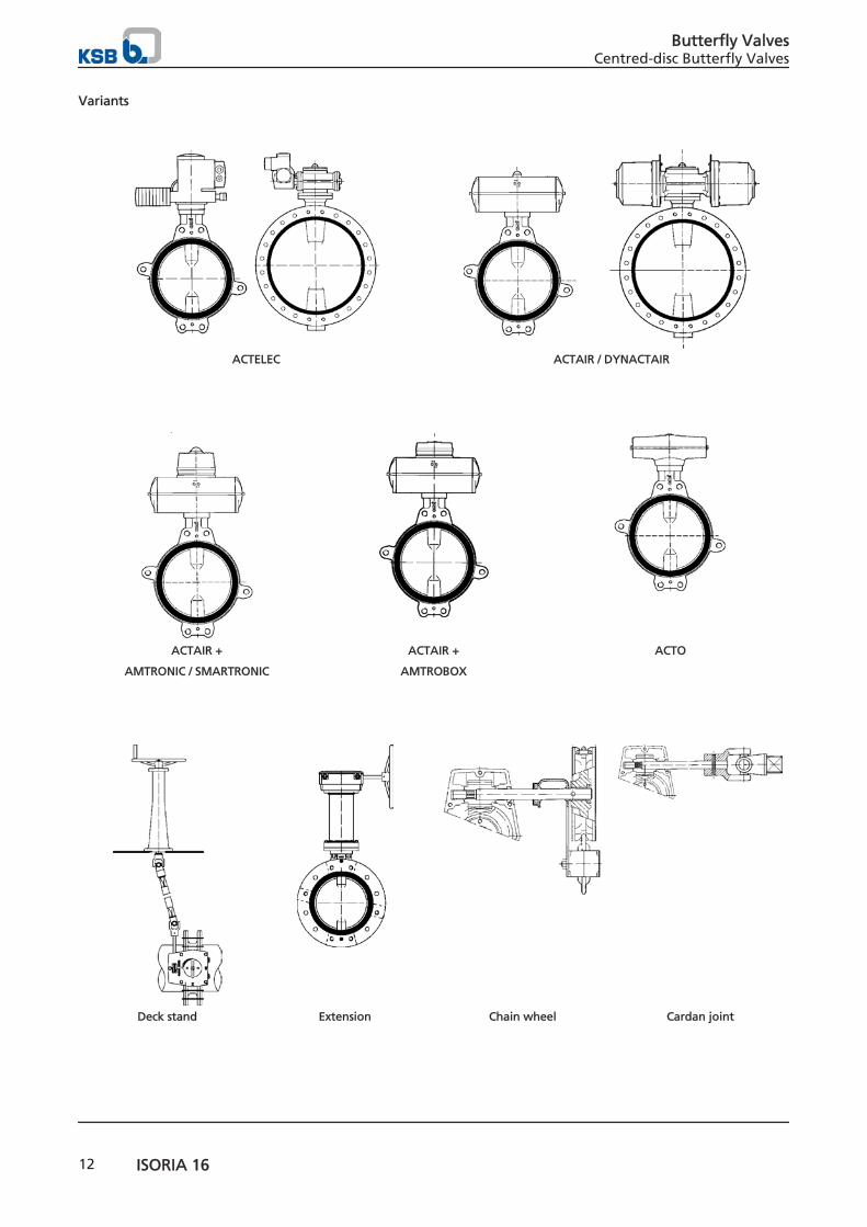
Variants
ACTELEC ACTAIR / DYNACTAIR
ACTAIR +
AMTRONIC / SMARTRONIC
ACTAIR +
AMTROBOX
ACTO
Deck stand Extension Chain wheel Cardan joint
Butterfly ValvesCentred-disc Butterfly Valves
12 ISORIA 16
Notes on installation
Connections
The valves can be installed between the following lineconnections (other line connections on request):
▪ EN 1092 PN 10 and 16
▪ ASME B16.1 Cl.125 and B16.5 Cl.150
▪ ASME B16.47 Cl.150 Series A
▪ MSS SP 44 Cl.150
▪ AWWA C207 Cl. B, D and E
▪ AS 2129 Tables D and E
▪ BS 10 Tables D and E
▪ JIS B2220, B2238 and B2239 5K, 10K,16K and 20K
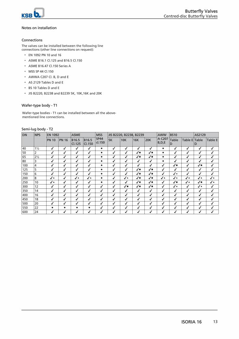
Wafer-type body - T1
Wafer-type bodies - T1 can be installed between all the above-mentioned line connections.
Semi-lug body - T2
DN NPS EN 1092 ASME MSSSP44cl.150
JIS B2220, B2238, B2239 AWWA C207B,D,E
BS10 AS2129
PN 10 PN 16 B16.5Cl.125
B16.5Cl.150
5K 10K 16K 20K TableD
Table E TableD
Table E
40 1½ ✔ ✔ ✔ ✔ ● ✔ ✔ ✔ ✔ ● ✔ ✔ ✔ ✔50 2 ✔ ✔ ✔ ✔ ● ✔ ✔ ✔■ ✔■ ● ✔ ✔ ✔ ✔65 2½ ✔ ✔ ✔ ✔ ● ✔ ✔ ✔■ ✔■ ● ✔ ✔ ✔ ✔80 3 ✔ ✔ ✔ ✔ ● ✔ ✔ ✔ ✔ ● ✔ ✔ ✔ ✔100 4 ✔ ✔ ✔ ✔ ● ✔ ✔ ✔ ✔ ✔ ✔■ ✔ ✔■ ✔125 5 ✔ ✔ ✔ ✔ ● ✔ ✔ ✔■ ✔■ ✔ ✔ ✔ ✔ ✔150 6 ✔ ✔ ✔ ✔ ● ✔ ✔ ✔■ ✔■ ✔ ✔▲ ✔ ✔ ✔200 8 ✔▲ ✔ ✔▲ ✔▲ ● ✔ ✔▲ ✔■ ✔■ ✔▲ ✔▲ ✔▲ ✔▲ ✔▲250 10 ✔▲ ✔ ✔ ✔ ● ✔ ✔ ✔■ ✔■ ✔ ✔■ ✔▲ ✔■ ✔▲300 12 ✔ ✔ ✔ ✔ ✔ ✔ ✔■ ✔■ ✔■ ✔ ✔▲ ✔ ✔▲ ✔350 14 ✔ ✔ ✔ ✔ ✔ ✔ ✔ ✔ ✔ ✔ ✔ ✔ ✔ ✔400 16 ✔ ✔ ✔ ✔ ✔ ✔ ✔ ✔ ✔ ✔ ✔ ✔ ✔ ✔450 18 ✔ ✔ ✔ ✔ ✔ ✔ ✔ ✔ ✔ ✔ ✔ ✔ ✔ ✔500 20 ✔ ✔ ✔ ✔ ✔ ✔ ✔ ✔ ✔ ✔ ✔ ✔ ✔ ✔550 22 ● ● ● ● ✔ ✔ ✔ ✔ ✔ ✔ ✔ ✔ ✔ ✔600 24 ✔ ✔ ✔ ✔ ✔ ✔ ✔ ✔ ✔ ✔ ✔ ✔ ✔ ✔
Butterfly ValvesCentred-disc Butterfly Valves
ISORIA 16 13
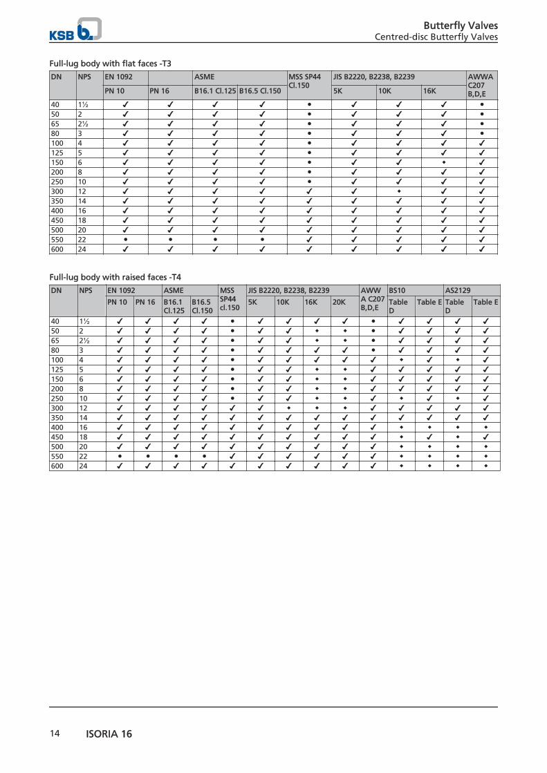
Full-lug body with flat faces -T3
DN NPS EN 1092 ASME MSS SP44Cl.150
JIS B2220, B2238, B2239 AWWAC207B,D,EPN 10 PN 16 B16.1 Cl.125 B16.5 Cl.150 5K 10K 16K
40 1½ ✔ ✔ ✔ ✔ ● ✔ ✔ ✔ ●50 2 ✔ ✔ ✔ ✔ ● ✔ ✔ ✔ ●65 2½ ✔ ✔ ✔ ✔ ● ✔ ✔ ✔ ●80 3 ✔ ✔ ✔ ✔ ● ✔ ✔ ✔ ●100 4 ✔ ✔ ✔ ✔ ● ✔ ✔ ✔ ✔125 5 ✔ ✔ ✔ ✔ ● ✔ ✔ ✔ ✔150 6 ✔ ✔ ✔ ✔ ● ✔ ✔ ◆ ✔200 8 ✔ ✔ ✔ ✔ ● ✔ ✔ ✔ ✔250 10 ✔ ✔ ✔ ✔ ● ✔ ✔ ✔ ✔300 12 ✔ ✔ ✔ ✔ ✔ ✔ ◆ ✔ ✔350 14 ✔ ✔ ✔ ✔ ✔ ✔ ✔ ✔ ✔400 16 ✔ ✔ ✔ ✔ ✔ ✔ ✔ ✔ ✔450 18 ✔ ✔ ✔ ✔ ✔ ✔ ✔ ✔ ✔500 20 ✔ ✔ ✔ ✔ ✔ ✔ ✔ ✔ ✔550 22 ● ● ● ● ✔ ✔ ✔ ✔ ✔600 24 ✔ ✔ ✔ ✔ ✔ ✔ ✔ ✔ ✔
Full-lug body with raised faces -T4
DN NPS EN 1092 ASME MSSSP44cl.150
JIS B2220, B2238, B2239 AWWA C207B,D,E
BS10 AS2129
PN 10 PN 16 B16.1Cl.125
B16.5Cl.150
5K 10K 16K 20K TableD
Table E TableD
Table E
40 1½ ✔ ✔ ✔ ✔ ● ✔ ✔ ✔ ✔ ● ✔ ✔ ✔ ✔50 2 ✔ ✔ ✔ ✔ ● ✔ ✔ ◆ ◆ ● ✔ ✔ ✔ ✔65 2½ ✔ ✔ ✔ ✔ ● ✔ ✔ ◆ ◆ ● ✔ ✔ ✔ ✔80 3 ✔ ✔ ✔ ✔ ● ✔ ✔ ✔ ✔ ● ✔ ✔ ✔ ✔100 4 ✔ ✔ ✔ ✔ ● ✔ ✔ ✔ ✔ ✔ ◆ ✔ ◆ ✔125 5 ✔ ✔ ✔ ✔ ● ✔ ✔ ◆ ◆ ✔ ✔ ✔ ✔ ✔150 6 ✔ ✔ ✔ ✔ ● ✔ ✔ ◆ ◆ ✔ ✔ ✔ ✔ ✔200 8 ✔ ✔ ✔ ✔ ● ✔ ✔ ◆ ◆ ✔ ✔ ✔ ✔ ✔250 10 ✔ ✔ ✔ ✔ ● ✔ ✔ ◆ ◆ ✔ ◆ ✔ ◆ ✔300 12 ✔ ✔ ✔ ✔ ✔ ✔ ◆ ◆ ◆ ✔ ✔ ✔ ✔ ✔350 14 ✔ ✔ ✔ ✔ ✔ ✔ ✔ ✔ ✔ ✔ ✔ ✔ ✔ ✔400 16 ✔ ✔ ✔ ✔ ✔ ✔ ✔ ✔ ✔ ✔ ◆ ◆ ◆ ◆450 18 ✔ ✔ ✔ ✔ ✔ ✔ ✔ ✔ ✔ ✔ ◆ ✔ ◆ ✔500 20 ✔ ✔ ✔ ✔ ✔ ✔ ✔ ✔ ✔ ✔ ◆ ◆ ◆ ◆550 22 ● ● ● ● ✔ ✔ ✔ ✔ ✔ ✔ ◆ ◆ ◆ ◆600 24 ✔ ✔ ✔ ✔ ✔ ✔ ✔ ✔ ✔ ✔ ◆ ◆ ◆ ◆
Butterfly ValvesCentred-disc Butterfly Valves
14 ISORIA 16
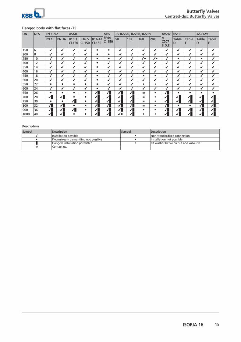
Flanged body with flat faces -T5
DN NPS EN 1092 ASME MSSSP44Cl.150
JIS B2220, B2238, B2239 AWWAC207B,D,E
BS10 AS2129
PN 10 PN 16 B16.1Cl.150
B16.5Cl.150
B16.47Cl.150
5K 10K 16K 20K TableD
TableE
TableD
TableE
150 6 ✔ ✔ ✔ ✔ ● ● ✔ ✔ ✔ ✔ ✔ ✔ ✔ ✔ ✔200 8 ✔ ✔ ✔ ✔ ● ● ✔ ✔ ✔ ✔ ✔ ✔ ✔ ✔ ✔250 10 ✔ ✔ ✔ ✔ ● ● ✔ ✔ ✔■ ✔■ ✔ ◆ ✔ ◆ ✔300 12 ✔ ✔ ✔ ✔ ● ✔ ✔ ✔ ✔ ✔ ✔ ✔ ✔ ✔ ✔350 14 ✔ ✔ ✔ ✔ ● ✔ ✔ ✔ ✔ ✔ ✔ ✔ ✔ ✔ ✔400 16 ✔ ✔ ✔ ✔ ● ✔ ✔ ✔ ✔ ✔ ✔ ✔ ✔ ✔ ✔450 18 ✔ ✔ ✔ ✔ ● ✔ ✔ ✔ ◆ ◆ ✔ ✔ ✔ ✔ ✔500 20 ✔ ✔ ✔ ✔ ● ✔ ✔ ✔ ✔ ✔ ✔ ✔ ✔ ✔ ✔550 22 ● ● ● ● ● ✔ ✔ ✔ ◆ ◆ ✔ ✔ ✔ ✔ ✔600 24 ✔ ✔ ✔ ✔ ● ✔ ✔ ✔ ✔ ✔ ✔ ✔ ✔ ✔ ✔650 26 ● ● ● ● ✔█ ✔█ ✔█ ✔█ ☎ ◆ ✔█ ● ● ● ●700 28 ✔█ ✔█ ● ● ✔█ ✔█ ✔█ ✔█ ☎ ◆ ✔█ ✔█ ✔█ ✔█ ✔█750 30 ● ● ✔█ ● ✔█ ✔█ ✔█ ✔█ ☎ ◆ ✔█ ✔█ ✔█ ✔█ ✔█800 32 ✔█ ✔█ ● ● ✔█ ✔█ ✔█ ✔█ ☎ ◆ ✔█ ● ● ✔█ ✔█900 36 ✔█ ✔█ ✔█ ● ✔█ ✔█ ✔█ ✔█ ◆ ◆ ✔█ ✔█ ✔█ ✔█ ✔█1000 40 ✔█ ✔█ ● ● ✔█ ✔█ ✔■ ✔█ ◆ ◆ ✔█ ✔█ ✔█ ✔█ ✔█
Description
Symbol Description Symbol Description
✔ Installation possible ● Non-standardised connection■ Downstream dismantling not possible ◆ Installation not possible█ Flanged installation permitted ▲ Fit washer between nut and valve rib.☎ Contact us.
Butterfly ValvesCentred-disc Butterfly Valves
ISORIA 16 15
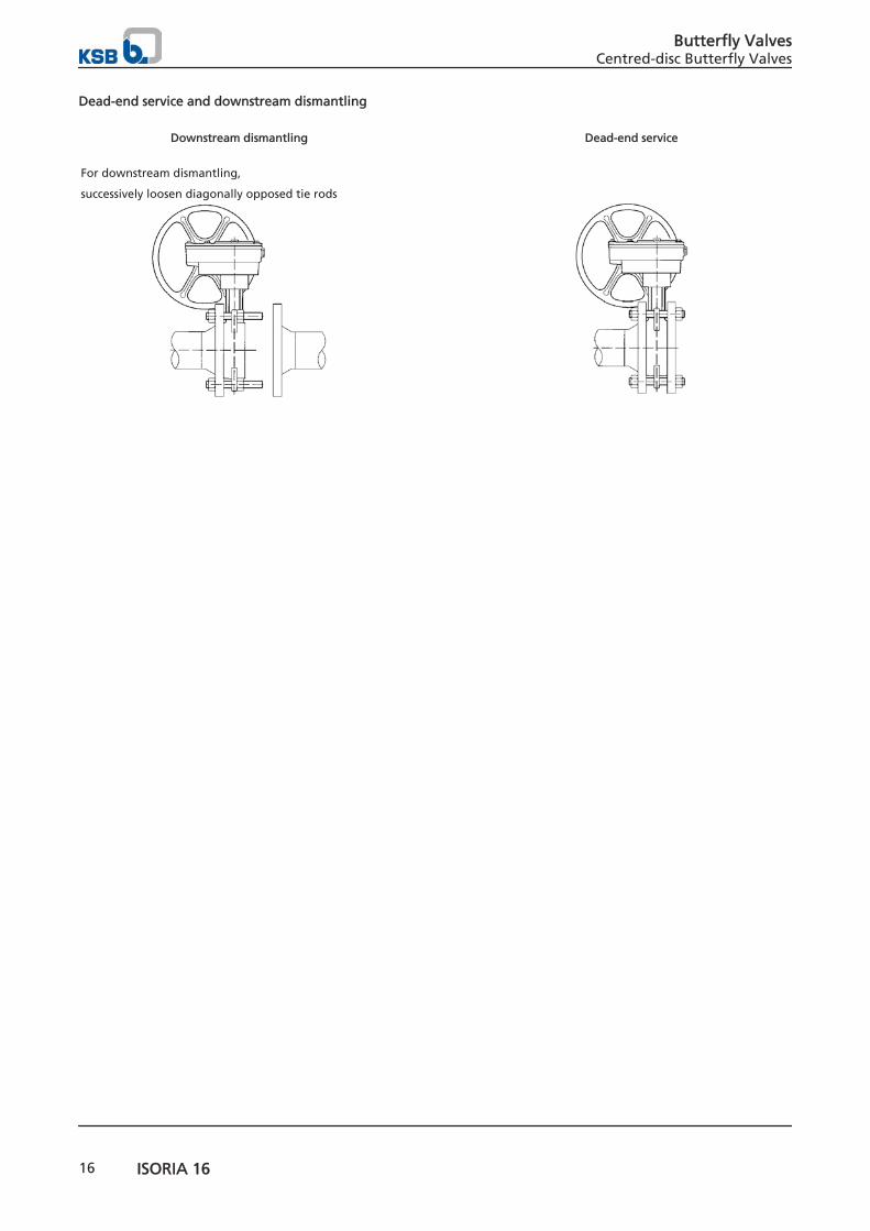
Dead-end service and downstream dismantling
Downstream dismantling Dead-end service
For downstream dismantling,
successively loosen diagonally opposed tie rods
Butterfly ValvesCentred-disc Butterfly Valves
16 ISORIA 16
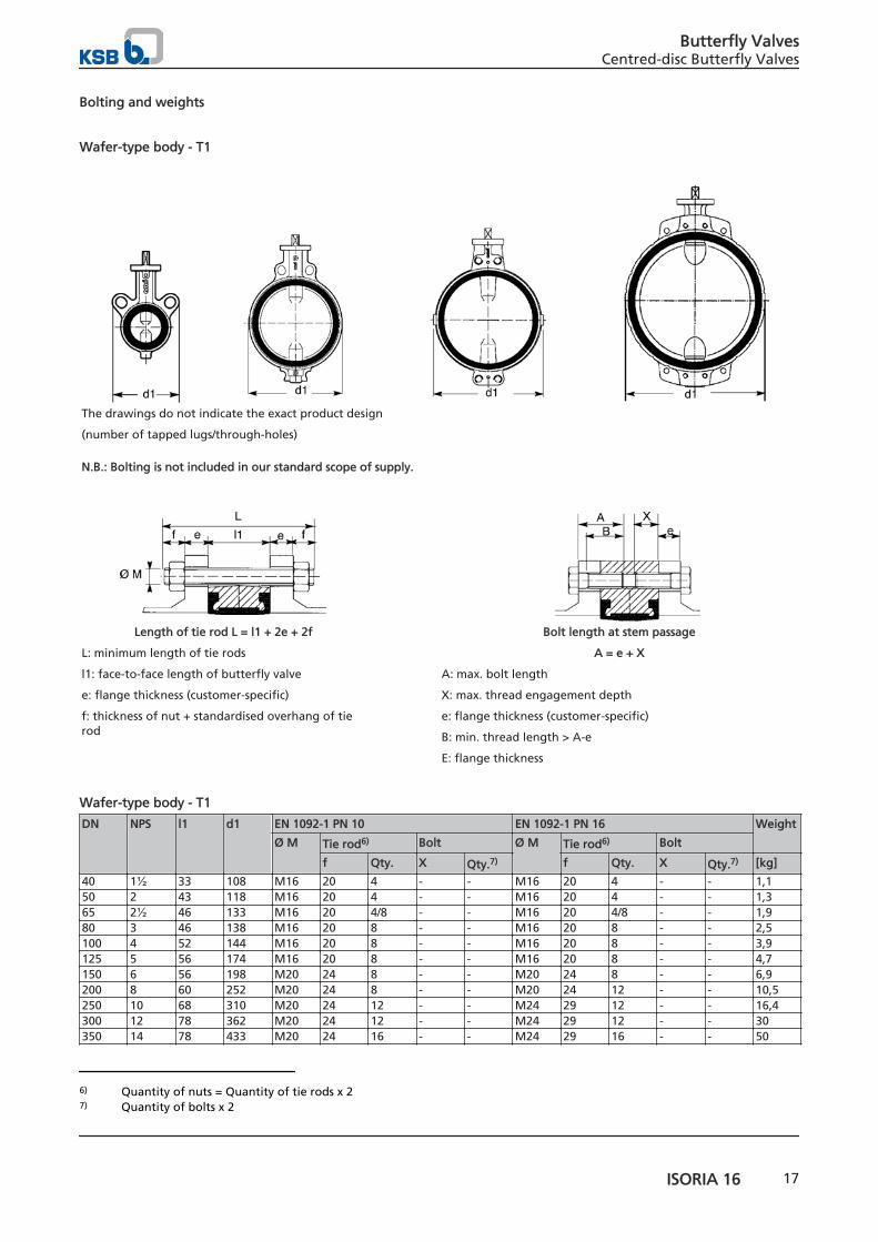
Bolting and weights
Wafer-type body - T1
The drawings do not indicate the exact product design
(number of tapped lugs/through-holes) N.B.: Bolting is not included in our standard scope of supply.
Length of tie rod L = l1 + 2e + 2f
L: minimum length of tie rods
l1: face-to-face length of butterfly valve
e: flange thickness (customer-specific)
f: thickness of nut + standardised overhang of tierod
Bolt length at stem passage
A = e + X
A: max. bolt length
X: max. thread engagement depth
e: flange thickness (customer-specific)
B: min. thread length > A-e
E: flange thickness
Wafer-type body - T1
DN NPS l1 d1 EN 1092-1 PN 10 EN 1092-1 PN 16 Weight
Ø M Tie rod6) Bolt Ø M Tie rod6) Bolt
f Qty. X Qty.7) f Qty. X Qty.7) [kg]
40 1½ 33 108 M16 20 4 - - M16 20 4 - - 1,150 2 43 118 M16 20 4 - - M16 20 4 - - 1,365 2½ 46 133 M16 20 4/8 - - M16 20 4/8 - - 1,980 3 46 138 M16 20 8 - - M16 20 8 - - 2,5100 4 52 144 M16 20 8 - - M16 20 8 - - 3,9125 5 56 174 M16 20 8 - - M16 20 8 - - 4,7150 6 56 198 M20 24 8 - - M20 24 8 - - 6,9200 8 60 252 M20 24 8 - - M20 24 12 - - 10,5250 10 68 310 M20 24 12 - - M24 29 12 - - 16,4300 12 78 362 M20 24 12 - - M24 29 12 - - 30350 14 78 433 M20 24 16 - - M24 29 16 - - 50
6) Quantity of nuts = Quantity of tie rods x 27) Quantity of bolts x 2
Butterfly ValvesCentred-disc Butterfly Valves
ISORIA 16 17
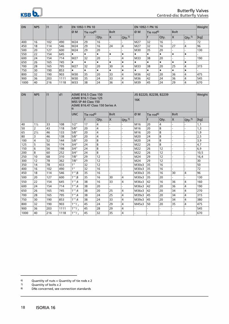
DN NPS l1 d1 EN 1092-1 PN 10 EN 1092-1 PN 16 Weight
Ø M Tie rod6) Bolt Ø M Tie rod6) Bolt
f Qty. X Qty.7) f Qty. X Qty.7) [kg]
400 16 102 490 M24 29 16 - - M27 32 16 - - 72450 18 114 546 M24 29 16 24 4 M27 32 16 27 4 96500 20 127 600 M24 29 20 - - M30 35 20 - - 130550 22 154 645 ● ● ● ● ● ● ● ● ● ● -600 24 154 714 M27 32 20 - 4 M33 38 20 - - 190650 26 165 745 ● ● ● ● ● ● ● ● ● ● -700 28 165 795 M27 32 20 30 4 M33 38 20 25 4 315750 30 190 853 ● ● ● ● ● ● ● ● ● ● -800 32 190 903 M30 35 20 33 4 M36 42 20 36 4 475900 36 203 1111 M30 35 24 33 4 M36 42 24 36 4 5451000 40 216 1118 M33 38 24 36 4 M39 45 24 29 4 670
DN NPS l1 d1 ASME B16.5 Class 150 ASME B16.1 Class 125MSS SP 44 Class 150ASME B16.47 Class 150 Series A8)
JIS B2220, B2238, B2239
16K
Weight
UNC Tie rod6) Bolt Ø M Tie rod6) Bolt
f Qty. X Qty.7) f Qty. X Qty.7) [kg]
40 1½ 33 108 1/2" 17 4 - - M16 20 4 - - 1,150 2 43 118 5/8" 20 4 - - M16 20 8 - - 1,365 2½ 46 133 5/8" 20 4 - - M16 20 8 - - 1,980 3 46 138 5/8" 20 4 - - M20 24 8 - - 2,5100 4 52 144 5/8" 20 8 - - M20 24 8 - - 3,9125 5 56 174 3/4" 24 8 - - M22 26 8 - - 4,7150 6 56 198 3/4" 24 8 - - M22 26 12 - - 6,9200 8 60 252 3/4" 24 8 - - M22 26 12 - - 10,5250 10 68 310 7/8" 29 12 - - M24 29 12 - - 16,4300 12 78 362 7/8" 29 12 - - M24 29 12 - - 30350 14 78 433 1" 32 12 - - M30x3 35 16 - - 50400 16 102 490 1" 32 16 - - M30x3 35 16 - - 72450 18 114 546 1"1
/8 35 16 - - M30x3 35 16 30 4 96500 20 127 600 1"1
/8 35 16 30 4 M30x3 35 20 - - 130550 22 154 645 1"1
/4 38 16 33 4 M36x3 42 16 36 4 160600 24 154 714 1"1
/4 38 20 - - M36x3 42 20 36 4 190650 26 165 745 1"1
/4 38 20 25 4 M36x3 42 20 34 4 270700 28 165 795 1"1
/4 38 24 25 4 M39x3 45 20 34 4 315750 30 190 853 1"1
/4 38 24 33 4 M39x3 45 20 34 4 380800 32 190 903 1"1/ 2 45 24 29 4 M45x3 50 20 35 4 475900 36 203 1111 1"1/ 2 45 28 29 4 - - - - - 5451000 40 216 1118 1"1/ 2 45 32 35 4 - - - - - 670
6) Quantity of nuts = Quantity of tie rods x 27) Quantity of bolts x 28) DNs concerned, see connection standards
Butterfly ValvesCentred-disc Butterfly Valves
18 ISORIA 16
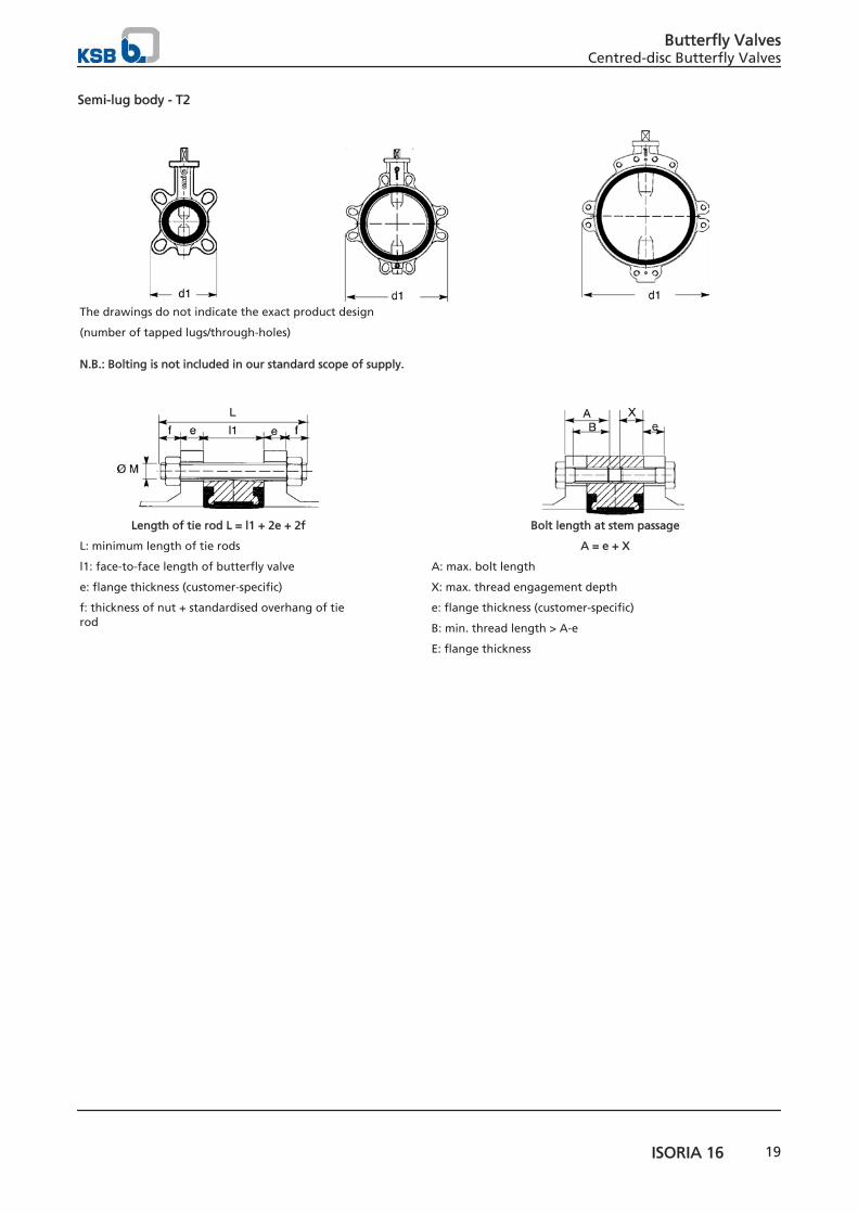
Semi-lug body - T2
The drawings do not indicate the exact product design
(number of tapped lugs/through-holes) N.B.: Bolting is not included in our standard scope of supply.
Length of tie rod L = l1 + 2e + 2f
L: minimum length of tie rods
l1: face-to-face length of butterfly valve
e: flange thickness (customer-specific)
f: thickness of nut + standardised overhang of tierod
Bolt length at stem passage
A = e + X
A: max. bolt length
X: max. thread engagement depth
e: flange thickness (customer-specific)
B: min. thread length > A-e
E: flange thickness
Butterfly ValvesCentred-disc Butterfly Valves
ISORIA 16 19
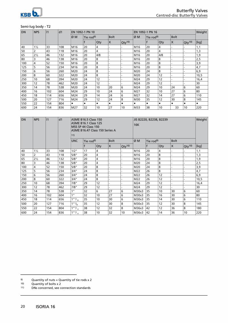
Semi-lug body - T2
DN NPS l1 d1 EN 1092-1 PN 10 EN 1092-1 PN 16 Weight
Ø M Tie rod9) Bolt Ø M Tie rod9) Bolt
f Qty X Qty10) f Qty X Qty10) [kg]
40 1½ 33 108 M16 20 4 - - M16 20 4 - - 1,150 2 43 118 M16 20 4 - - M16 20 4 - - 1,365 2½ 46 132 M16 20 4/8 - - M16 20 4/8 - - 1,980 3 46 138 M16 20 8 - - M16 20 8 - - 2,5100 4 52 150 M16 20 8 - - M16 20 8 - - 3,9125 5 56 234 M16 20 8 - - M16 20 8 - - 4,7150 6 56 260 M20 24 8 - - M20 24 8 - - 6,9200 8 60 322 M20 24 8 - - M20 24 12 - - 10,5250 10 68 394 M20 24 12 - - M24 29 12 - - 16,4300 12 78 462 M20 24 12 - - M24 29 12 - - 30350 14 78 538 M20 24 10 20 6 M24 29 10 24 6 60400 16 102 604 M24 29 10 24 6 M27 32 10 27 6 80450 18 114 656 M24 29 14 24 6 M27 32 14 27 6 110500 20 127 716 M24 29 12 24 8 M30 35 12 30 8 145550 22 154 804 ● ● ● ● ● ● ● ● ● ● ●600 24 154 836 M27 32 10 27 10 M33 38 10 33 10 220
DN NPS l1 d1 ASME B16.5 Class 150 ASME B16.1 Class 125MSS SP 44 Class 150ASME B16.47 Class 150 Series A
11)
JIS B2220, B2238, B2239
16K
Weight
UNC Tie rod9) Bolt Ø M Tie rod9) Bolt
f Qty X Qty10) f Qty X Qty10) [kg]
40 1½ 33 108 1/2" 17 4 - - M16 20 4 - - 1,150 2 43 118 5/8" 20 4 - - M16 20 8 - - 1,365 2½ 46 132 5/8" 20 4 - - M16 20 8 - - 1,980 3 46 138 5/8" 20 4 - - M20 24 8 - - 2,5100 4 52 150 5/8" 20 8 - - M20 24 8 - - 3,9125 5 56 234 3/4" 24 8 - - M22 26 8 - - 4,7150 6 56 260 3/4" 24 8 - - M22 26 12 - - 6,9200 8 60 322 3/4" 24 8 - - M22 26 12 - - 10,5250 10 68 394 7/8" 29 12 - - M24 29 12 - - 16,4300 12 78 462 7/8" 29 12 - - M24 29 12 - - 30350 14 78 538 1" 32 6 27 6 M30x3 35 10 30 6 60400 16 102 604 1" 32 10 27 6 M30x3 35 16 30 6 80450 18 114 656 1"1/ 8 35 10 30 6 M30x3 35 14 30 6 110500 20 127 716 1"1/8 35 12 30 8 M30x3 35 12 30 8 145550 22 154 804 1"1/ 4 38 12 32 8 M36x3 42 12 36 8 180600 24 154 836 1"1/ 4 38 10 32 10 M36x3 42 14 36 10 220
9) Quantity of nuts = Quantity of tie rods x 210) Quantity of bolts x 211) DNs concerned, see connection standards
Butterfly ValvesCentred-disc Butterfly Valves
20 ISORIA 16
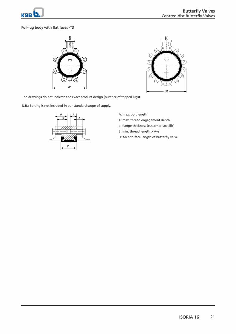
Full-lug body with flat faces -T3
The drawings do not indicate the exact product design (number of tapped lugs). N.B.: Bolting is not included in our standard scope of supply.
A: max. bolt length
X: max. thread engagement depth
e: flange thickness (customer-specific)
B: min. thread length > A-e
l1: face-to-face length of butterfly valve
Butterfly ValvesCentred-disc Butterfly Valves
ISORIA 16 21
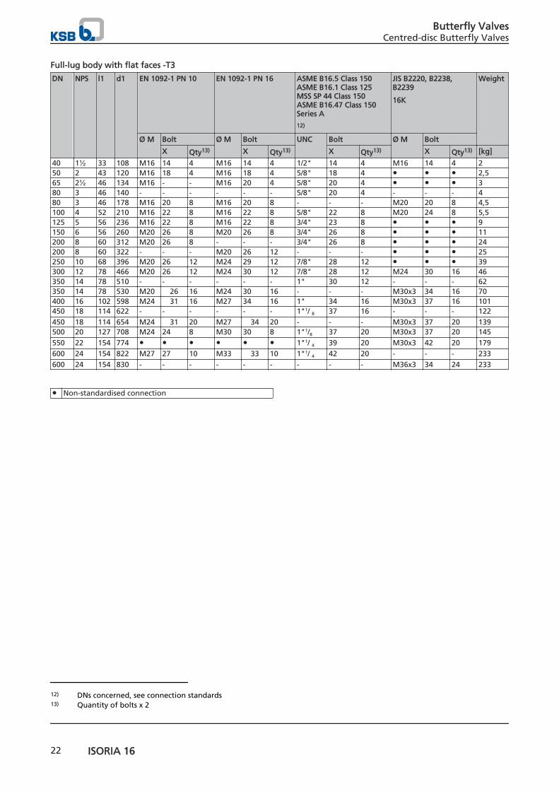
Full-lug body with flat faces -T3
DN NPS l1 d1 EN 1092-1 PN 10 EN 1092-1 PN 16 ASME B16.5 Class 150 ASME B16.1 Class 125MSS SP 44 Class 150ASME B16.47 Class 150Series A
12)
JIS B2220, B2238,B2239
16K
Weight
Ø M Bolt Ø M Bolt UNC Bolt Ø M Bolt
X Qty13) X Qty13) X Qty13) X Qty13) [kg]
40 1½ 33 108 M16 14 4 M16 14 4 1/2" 14 4 M16 14 4 250 2 43 120 M16 18 4 M16 18 4 5/8" 18 4 ● ● ● 2,565 2½ 46 134 M16 - - M16 20 4 5/8" 20 4 ● ● ● 380 3 46 140 - - - - - - 5/8" 20 4 - - - 480 3 46 178 M16 20 8 M16 20 8 - - - M20 20 8 4,5100 4 52 210 M16 22 8 M16 22 8 5/8" 22 8 M20 24 8 5,5125 5 56 236 M16 22 8 M16 22 8 3/4" 23 8 ● ● ● 9150 6 56 260 M20 26 8 M20 26 8 3/4" 26 8 ● ● ● 11200 8 60 312 M20 26 8 - - - 3/4" 26 8 ● ● ● 24200 8 60 322 - - - M20 26 12 - - - ● ● ● 25250 10 68 396 M20 26 12 M24 29 12 7/8" 28 12 ● ● ● 39300 12 78 466 M20 26 12 M24 30 12 7/8" 28 12 M24 30 16 46350 14 78 510 - - - - - - 1" 30 12 - - - 62350 14 78 530 M20 26 16 M24 30 16 - - - M30x3 34 16 70400 16 102 598 M24 31 16 M27 34 16 1" 34 16 M30x3 37 16 101450 18 114 622 - - - - - - 1"1/ 8 37 16 - - - 122450 18 114 654 M24 31 20 M27 34 20 - - - M30x3 37 20 139500 20 127 708 M24 24 8 M30 30 8 1"1/8 37 20 M30x3 37 20 145550 22 154 774 ● ● ● ● ● ● 1"1/ 4 39 20 M30x3 42 20 179600 24 154 822 M27 27 10 M33 33 10 1"1/ 4 42 20 - - - 233600 24 154 830 - - - - - - - - - M36x3 34 24 233
● Non-standardised connection
12) DNs concerned, see connection standards13) Quantity of bolts x 2
Butterfly ValvesCentred-disc Butterfly Valves
22 ISORIA 16

Full-lug body with raised faces -T4
The drawings do not indicate the exact product design (number of tapped lugs). N.B.: Bolting is not included in our standard scope of supply.
A: max. bolt length
X: max. thread engagement depth
e: flange thickness (customer-specific)
B: min. thread length > A-e
E: flange thickness
Butterfly ValvesCentred-disc Butterfly Valves
ISORIA 16 23
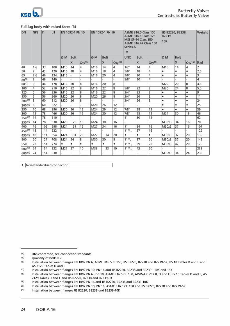
Full-lug body with raised faces -T4
DN NPS l1 d1 EN 1092-1 PN 10 EN 1092-1 PN 16 ASME B16.5 Class 150 ASME B16.1 Class 125MSS SP 44 Class 150ASME B16.47 Class 150Series A
14)
JIS B2220, B2238,B2239
16K
Weight
Ø M Bolt Ø M Bolt UNC Bolt Ø M Bolt
X Qty15) X Qty15) X Qty15) X Qty15) [kg]
40 1½ 33 108 M16 14 4 M16 14 4 1/2" 14 4 M16 14 4 250 2 43 120 M16 18 4 M16 18 4 5/8" 18 4 ● ● ● 2,565 2½ 46 134 M16 - - M16 20 4 5/8" 20 4 ● ● ● 38016) 3 46 140 - - - - - - 5/8" 20 4 - - - 4
8017) 3 46 178 M16 20 8 M16 20 8 - - - M20 20 8 4,5100 4 52 210 M16 22 8 M16 22 8 5/8" 22 8 M20 24 8 5,5125 5 56 236 M16 22 8 M16 22 8 3/4" 23 8 ● ● ● 9150 6 56 260 M20 26 8 M20 26 8 3/4" 26 8 ● ● ● 1120018) 8 60 312 M20 26 8 - - - 3/4" 26 8 ● ● ● 24
20019) 8 60 322 - - - M20 26 12 - - - ● ● ● 25250 10 68 396 M20 26 12 M24 29 12 7/8" 28 12 ● ● ● 39300 12 78 466 M20 26 12 M24 30 12 7/8" 28 12 M24 30 16 4635016) 14 78 510 - - - - - - 1" 30 12 - - - 62
35017) 14 78 530 M20 26 16 M24 30 16 - - - M30x3 34 16 70400 16 102 598 M24 31 16 M27 34 16 1" 34 16 M30x3 37 16 10145016) 18 114 622 - - - - - - 1"1/ 8 37 16 - - - 122
45017) 18 114 654 M24 31 20 M27 34 20 ● ● ● M30x3 37 20 139500 20 127 708 M24 24 8 M30 30 8 1"1/8 37 20 M30x3 37 20 145550 22 154 774 ● ● ● ● ● ● 1"1/ 4 39 20 M36x3 42 20 179
60020) 24 154 822 M27 27 10 M33 33 10 1"1/ 4 42 20 - - - 233
60021) 24 154 830 - - - - - - - - - M36x3 34 24 233
● Non-standardised connection
14) DNs concerned, see connection standards15) Quantity of bolts x 216) Installation between flanges EN 1092 PN 6, ASME B16.5 Cl.150, JIS B2220, B2238 and B2239-5K, BS 10 Tables D and E and
AS 2129 Tables D and E17) Installation between flanges EN 1092 PN 10, PN 16 and JIS B2220, B2238 and B2239 - 10K and 16K18) Installation between flanges EN 1092 PN 6 und 10, ASME B16.5 Cl. 150, AWWA C 207 B, D and E, BS 10 Tables D and E, AS
2129 Tables D and E and JIS B2220, B2238 and B2239-5K19) Installation between flanges EN 1092 PN 16 and JIS B2220, B2238 and B2239-10K20) Installation between flanges EN 1092 PN 10, PN 16, ASME B16.5 Cl. 150 and JIS B2220, B2238 and B2239-5K21) Installation between flanges JIS B2220, B2238 und B2239-10K
Butterfly ValvesCentred-disc Butterfly Valves
24 ISORIA 16
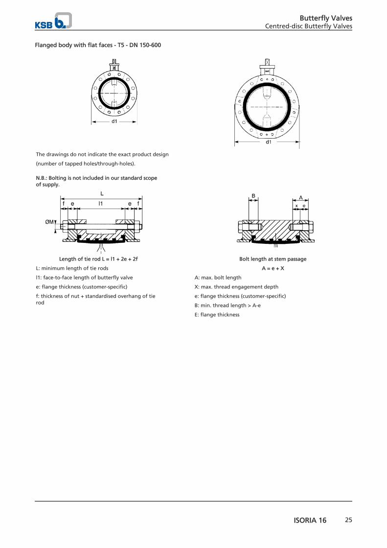
Flanged body with flat faces - T5 - DN 150-600
The drawings do not indicate the exact product design
(number of tapped holes/through-holes).
N.B.: Bolting is not included in our standard scopeof supply.
Length of tie rod L = l1 + 2e + 2f
L: minimum length of tie rods
l1: face-to-face length of butterfly valve
e: flange thickness (customer-specific)
f: thickness of nut + standardised overhang of tierod
Bolt length at stem passage
A = e + X
A: max. bolt length
X: max. thread engagement depth
e: flange thickness (customer-specific)
B: min. thread length > A-e
E: flange thickness
Butterfly ValvesCentred-disc Butterfly Valves
ISORIA 16 25
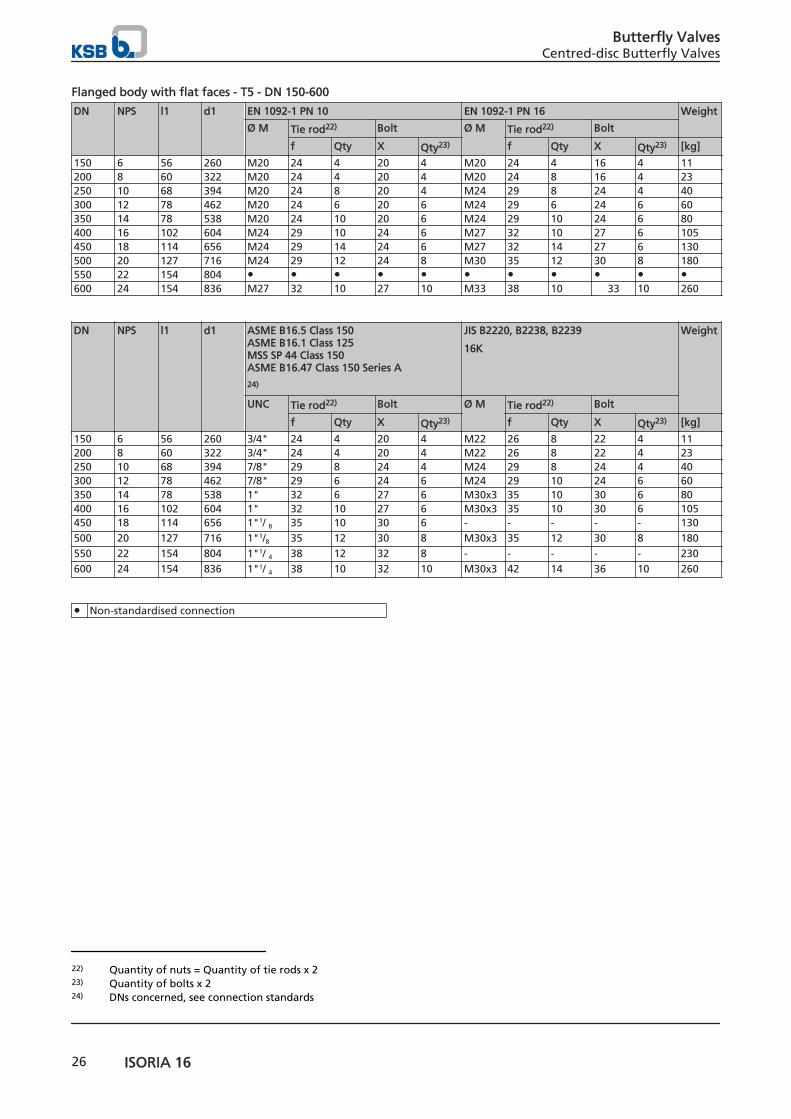
Flanged body with flat faces - T5 - DN 150-600
DN NPS l1 d1 EN 1092-1 PN 10 EN 1092-1 PN 16 Weight
Ø M Tie rod22) Bolt Ø M Tie rod22) Bolt
f Qty X Qty23) f Qty X Qty23) [kg]
150 6 56 260 M20 24 4 20 4 M20 24 4 16 4 11200 8 60 322 M20 24 4 20 4 M20 24 8 16 4 23250 10 68 394 M20 24 8 20 4 M24 29 8 24 4 40300 12 78 462 M20 24 6 20 6 M24 29 6 24 6 60350 14 78 538 M20 24 10 20 6 M24 29 10 24 6 80400 16 102 604 M24 29 10 24 6 M27 32 10 27 6 105450 18 114 656 M24 29 14 24 6 M27 32 14 27 6 130500 20 127 716 M24 29 12 24 8 M30 35 12 30 8 180550 22 154 804 ● ● ● ● ● ● ● ● ● ● ●600 24 154 836 M27 32 10 27 10 M33 38 10 33 10 260
DN NPS l1 d1 ASME B16.5 Class 150 ASME B16.1 Class 125MSS SP 44 Class 150ASME B16.47 Class 150 Series A
24)
JIS B2220, B2238, B2239
16K
Weight
UNC Tie rod22) Bolt Ø M Tie rod22) Bolt
f Qty X Qty23) f Qty X Qty23) [kg]
150 6 56 260 3/4" 24 4 20 4 M22 26 8 22 4 11200 8 60 322 3/4" 24 4 20 4 M22 26 8 22 4 23250 10 68 394 7/8" 29 8 24 4 M24 29 8 24 4 40300 12 78 462 7/8" 29 6 24 6 M24 29 10 24 6 60350 14 78 538 1" 32 6 27 6 M30x3 35 10 30 6 80400 16 102 604 1" 32 10 27 6 M30x3 35 10 30 6 105450 18 114 656 1"1/ 8 35 10 30 6 - - - - - 130500 20 127 716 1"1/8 35 12 30 8 M30x3 35 12 30 8 180550 22 154 804 1"1/ 4 38 12 32 8 - - - - - 230600 24 154 836 1"1/ 4 38 10 32 10 M30x3 42 14 36 10 260
● Non-standardised connection
22) Quantity of nuts = Quantity of tie rods x 223) Quantity of bolts x 224) DNs concerned, see connection standards
Butterfly ValvesCentred-disc Butterfly Valves
26 ISORIA 16
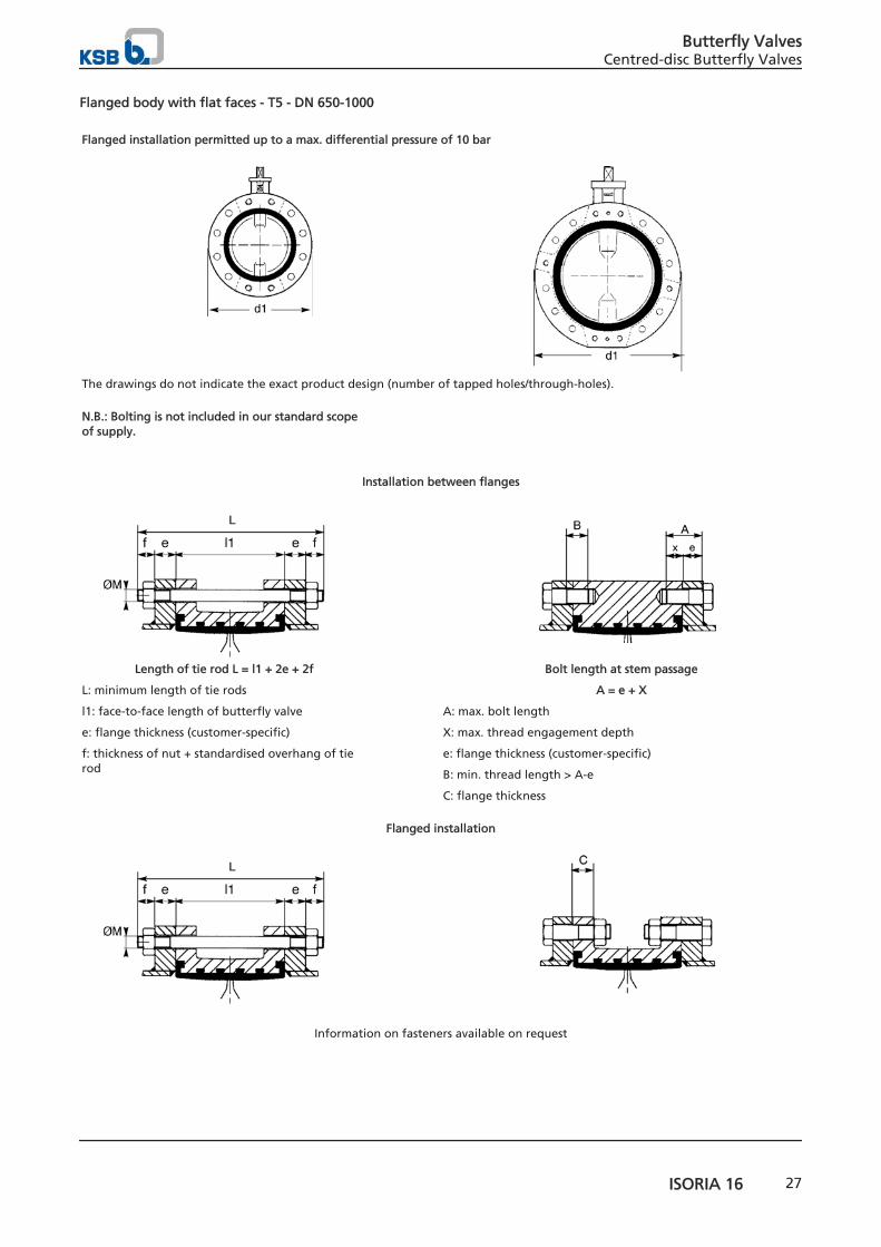
Flanged body with flat faces - T5 - DN 650-1000
Flanged installation permitted up to a max. differential pressure of 10 bar
The drawings do not indicate the exact product design (number of tapped holes/through-holes). N.B.: Bolting is not included in our standard scopeof supply.
Installation between flanges
Length of tie rod L = l1 + 2e + 2f
L: minimum length of tie rods
l1: face-to-face length of butterfly valve
e: flange thickness (customer-specific)
f: thickness of nut + standardised overhang of tierod
Bolt length at stem passage
A = e + X
A: max. bolt length
X: max. thread engagement depth
e: flange thickness (customer-specific)
B: min. thread length > A-e
C: flange thickness
Flanged installation
Information on fasteners available on request
Butterfly ValvesCentred-disc Butterfly Valves
ISORIA 16 27
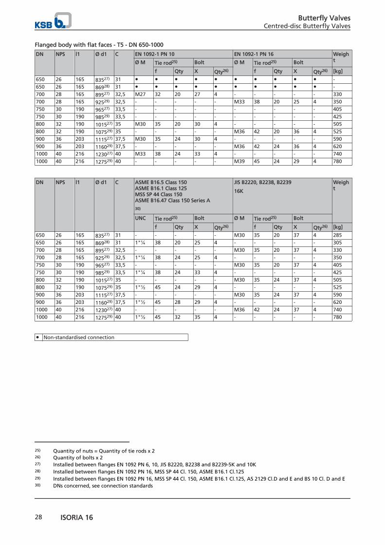
Flanged body with flat faces - T5 - DN 650-1000
DN NPS l1 Ø d1 C EN 1092-1 PN 10 EN 1092-1 PN 16 WeightØ M Tie rod25) Bolt Ø M Tie rod25) Bolt
f Qty X Qty26) f Qty X Qty26) [kg]
650 26 165 83527) 31 ● ● ● ● ● ● ● ● ● ● -650 26 165 86928) 31 ● ● ● ● ● ● ● ● ● ● -700 28 165 89527) 32,5 M27 32 20 27 4 - - - - - 330700 28 165 92529) 32,5 - - - - - M33 38 20 25 4 350750 30 190 96527) 33,5 - - - - - - - - - - 405750 30 190 98529) 33,5 - - - - - - - - - - 425800 32 190 101527) 35 M30 35 20 30 4 - - - - - 505800 32 190 107529) 35 - - - - - M36 42 20 36 4 525900 36 203 111527) 37,5 M30 35 24 30 4 - - - - - 590900 36 203 116029) 37,5 - - - - - M36 42 24 36 4 6201000 40 216 123027) 40 M33 38 24 33 4 - - - - - 7401000 40 216 127529) 40 - - - - - M39 45 24 29 4 780
DN NPS l1 Ø d1 C ASME B16.5 Class 150 ASME B16.1 Class 125MSS SP 44 Class 150ASME B16.47 Class 150 Series A
30)
JIS B2220, B2238, B2239
16K
Weight
UNC Tie rod25) Bolt Ø M Tie rod25) Bolt
f Qty X Qty26) f Qty X Qty26) [kg]
650 26 165 83527) 31 - - - - - M30 35 20 37 4 285650 26 165 86928) 31 1"¼ 38 20 25 4 - - - - - 305700 28 165 89527) 32,5 - - - - - M30 35 20 37 4 330700 28 165 92529) 32,5 1"¼ 38 24 25 4 - - - - - 350750 30 190 96527) 33,5 - - - - - M30 35 20 37 4 405750 30 190 98529) 33,5 1"¼ 38 24 33 4 - - - - - 425800 32 190 101527) 35 - - - - - M30 35 24 37 4 505800 32 190 107529) 35 1"½ 45 24 29 4 - - - - - 525900 36 203 111527) 37,5 - - - - - M30 35 24 37 4 590900 36 203 116029) 37,5 1"½ 45 28 29 4 - - - - - 6201000 40 216 123027) 40 - - - - - M36 42 24 37 4 7401000 40 216 127529) 40 1"½ 45 32 35 4 - - - - - 780
● Non-standardised connection
25) Quantity of nuts = Quantity of tie rods x 226) Quantity of bolts x 227) Installed between flanges EN 1092 PN 6, 10, JIS B2220, B2238 and B2239-5K and 10K28) Installed between flanges EN 1092 PN 16, MSS SP 44 Cl. 150, ASME B16.1 Cl.12529) Installed between flanges EN 1092 PN 16, MSS SP 44 Cl. 150, ASME B16.1 Cl.125, AS 2129 Cl.D and E and BS 10 Cl. D and E30) DNs concerned, see connection standards
Butterfly ValvesCentred-disc Butterfly Valves
28 ISORIA 16
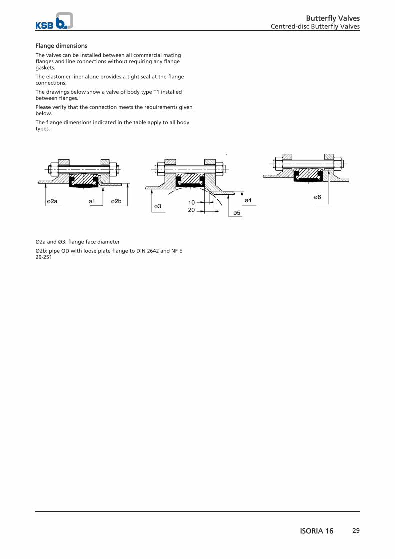
Flange dimensions
The valves can be installed between all commercial matingflanges and line connections without requiring any flangegaskets.
The elastomer liner alone provides a tight seal at the flangeconnections.
The drawings below show a valve of body type T1 installedbetween flanges.
Please verify that the connection meets the requirements givenbelow.
The flange dimensions indicated in the table apply to all bodytypes.
Ø2a and Ø3: flange face diameter
Ø2b: pipe OD with loose plate flange to DIN 2642 and NF E29-251
Butterfly ValvesCentred-disc Butterfly Valves
ISORIA 16 29
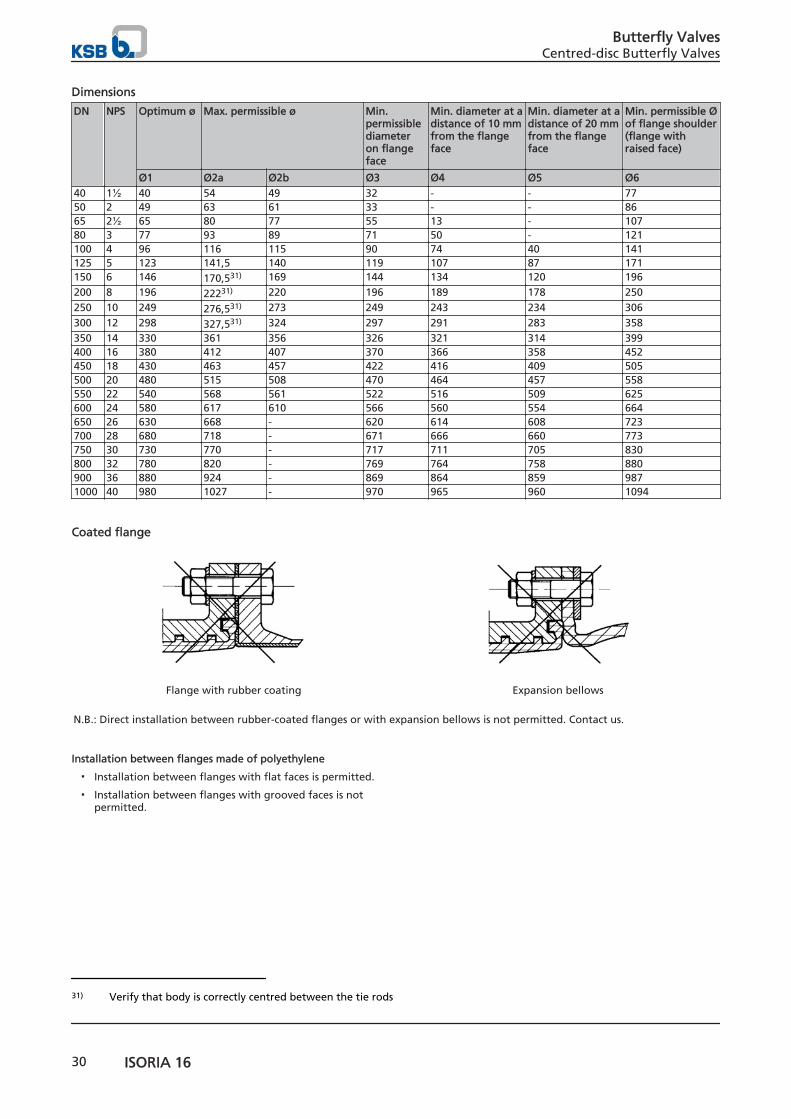
Dimensions
DN NPS Optimum ø Max. permissible ø Min.permissiblediameteron flangeface
Min. diameter at adistance of 10 mmfrom the flangeface
Min. diameter at adistance of 20 mmfrom the flangeface
Min. permissible Øof flange shoulder(flange withraised face)
Ø1 Ø2a Ø2b Ø3 Ø4 Ø5 Ø640 1½ 40 54 49 32 - - 7750 2 49 63 61 33 - - 8665 2½ 65 80 77 55 13 - 10780 3 77 93 89 71 50 - 121100 4 96 116 115 90 74 40 141125 5 123 141,5 140 119 107 87 171150 6 146 170,531) 169 144 134 120 196200 8 196 22231) 220 196 189 178 250250 10 249 276,531) 273 249 243 234 306300 12 298 327,531) 324 297 291 283 358350 14 330 361 356 326 321 314 399400 16 380 412 407 370 366 358 452450 18 430 463 457 422 416 409 505500 20 480 515 508 470 464 457 558550 22 540 568 561 522 516 509 625600 24 580 617 610 566 560 554 664650 26 630 668 - 620 614 608 723700 28 680 718 - 671 666 660 773750 30 730 770 - 717 711 705 830800 32 780 820 - 769 764 758 880900 36 880 924 - 869 864 859 9871000 40 980 1027 - 970 965 960 1094
Coated flange
Flange with rubber coating Expansion bellows
N.B.: Direct installation between rubber-coated flanges or with expansion bellows is not permitted. Contact us.
Installation between flanges made of polyethylene
▪ Installation between flanges with flat faces is permitted.
▪ Installation between flanges with grooved faces is notpermitted.
31) Verify that body is correctly centred between the tie rods
Butterfly ValvesCentred-disc Butterfly Valves
30 ISORIA 16


8445
.1/1
2-EN
21.0
7.20
14
KSB S.A.S.4, allée des Barbanniers • 92635 Gennevilliers Cedex (France)Tél. +33 1 41 47 75 00 • Fax +33 1 41 47 75 10 • www.ksb.com