ispring reverse osmosis water filtration systems · thank you for choosing the ispring reverse...
TRANSCRIPT

iSpring Reverse Osmosis Water Filtration Systems
INSTALLATION INSTRUCTIONS & OWNER’S MANUAL Ver 201606
Copyright ©20052016 ISPRING WATER SYSTEMS, LLC. All rights reserved.

Thank you for choosing the iSpring Reverse Osmosis Water Filtration System! Built from quality components and delivering exceptional performance, it has earned the WQA GOLD SEAL certification against NSF/ANSI STANDARD 58 for performance and material safety. Please review the attached iSpring RO Systems WQA Gold Seal Certification for details.
Please keep this owner’s manual for future reference. It includes the necessary information on how to properly install, operate, and
maintain your iSpring Reverse Osmosis water filtration system.
Page 1 www.123filter.com | (678) 2617611 | [email protected]

TABLE OF CONTENTS
Prior to Installation Page 4 Inspect the package Recommended tools list Operating conditions Components Identification How to use the QuickConnect fittings How to connect the compression fitting How to drill a ½” hole in your sink or countertop
Installation Steps Page 9 Step 1: Installing the Feed Water Adapter (AFW) Step 2: Installing the RO Step 3: Installing the Drain Saddle Step 4: Installing the Vertical Filters: Stages 1, 2, and 3 Step 5: Installing the Tank Shutoff Valve (TSV) Step 6: Installing the Reverse Osmosis Membrane Step 7: Tubing Hook Up (model specific substeps are marked with * ) Step 8: System Start Up (model specific substeps are marked with a * )
ISPRING RO SYSTEM MAINTENANCE Page 17 Stage 1 – 3 PreFilters Stage 4 RO Membrane: Replace every 2 – 3 years Stage 5 FT15 Inline Post Carbon Filter and Stage 6 Inline Alkaline Filter UV Filter (UVF11A) Ice Maker Kit (ICEK) Section 1: Knowledge Base Page 20
What Is Reverse Osmosis? How Effective Is Reverse Osmosis Filtration? What are the specific contaminants that a reverse osmosis system removes? Does Reverse Osmosis remove pharmaceuticals from water? Will a reverse osmosis water system taste as good as the water I pay $5.00 a bottle for? I have heard that reverse osmosis wastes a lot of water! What is an Alkaline Filter? What is a DI filter? What is a UV filter? What is a TDS meter? Maximum distance from tank to faucet What is an ASOV and what does it do? Does the UV filter run 24/7? Will the water out of UV filter be hot? How does your RCS5T tankless RO system compare to the GE Merlin 700GPD system?
Section 2: Troubleshooting Guide Page 24 Leaking from where the tubing is pushed into the quickconnect fitting Leaking around filter housing (Oring is too small or is not in place) Low water pressure at the RO faucet or output location Little water from the RO faucet Continuous Drain High TDS level in RO water Tastes and Odors in Product Water Faucet Leaks or Drips Cloudy Water and Ice Cubes After installation, the water out of the RO faucet is only a trickle Sudden drop in RO water production
Page 2 www.123filter.com | (678) 2617611 | [email protected]

Prior to Installation
Inspect the package Open the box and remove all of the components. Inspect them to ensure nothing was damaged during shipping. If any part is cracked or broken, please immediately contact iSpring Customer Support for replacement. Identify and get familiar with the components.
Recommended tools list ● Variable speed drill with two bits: ¼” (for drilling a hole on PVC drain pipe), ½” hollow diamond (for drilling
a hole on countertop for drinking faucet) ● 5/8”, 9/16” openend wrench, or adjustable wrench, pliers ● Phillips head screwdriver ● Scissors or utility knife
Operating conditions ● Maximum water pressure: 80 psi, otherwise a pressure regulator (part no. APR70) is required to lower the
psi to an adequate level. ● Minimum water pressure: 45 psi, otherwise a booster pump is necessary to raise the incoming water
pressure and improve the RO efficiency. ● Operating water temperature: 40 – 100 °F (4 37 °C) (This RO system is NOT designed for HOT water) ● Maximum TDS: 750 ppm ● Install this RO system in a location where it is safe from hot/cold weather and direct sunlight. Avoid hitting,
dropping, or dragging the system as this can cause cracks and leaks.
Page 3 www.123filter.com | (678) 2617611 | [email protected]
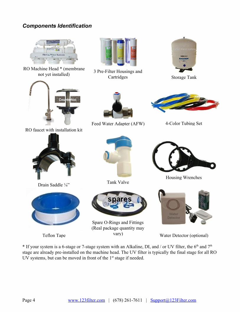
Components Identification
RO Machine Head * (membrane
not yet installed)
3 PreFilter Housings and
Cartridges
Storage Tank
RO faucet with installation kit
Feed Water Adapter (AFW)
4Color Tubing Set
Drain Saddle ¼”
Tank Valve
Housing Wrenches
Teflon Tape
Spare ORings and Fittings (Real package quantity may
vary)
Water Detector (optional) * If your system is a 6stage or 7stage system with an Alkaline, DI, and / or UV filter, the 6th and 7th stage are already preinstalled on the machine head. The UV filter is typically the final stage for all RO UV systems, but can be moved in front of the 1st stage if needed.
Page 4 www.123filter.com | (678) 2617611 | [email protected]

Installation Tips
How to use the QuickConnect fittings
Figure 1
To connect: 1. See Figure 1. Check and cut the tubing end squarely and cleanly with utility knife or scissors. 2. Make a ½” mark at the end of the tube so you will be able to confirm when the tube is inserted
fully into the fitting. 3. Remove the blue lock clip from the fitting with your nail. If the lock sleeve pops out of the
fitting when doing this, simply pop it back in. 4. Insert the tube into the fitting until you reach the ½” mark on the tube. You will feel resistance
when the tube reaches the small rubber O ring inside the fitting. You will need to wiggle the tube and apply additional pressure to get it past this O ring and create the seal. If the tube is not ½” into the fitting and past the O ring, no seal will be created and leaking will occur.
5. Once the tube is fully inserted into the fitting, pop the blue lock clip back on the fitting. This will lock the tube in place and prevent it from moving.
Figure 2
Figure 3
Page 5 www.123filter.com | (678) 2617611 | [email protected]

To disconnect:
1. See Figures 2 and 3. Remove the blue lock clip from the fitting. 2. With the blue lock clip removed, use your thumb and index finger to hold down the lock
sleeve. This will release the metal teeth holding the tube in place. While holding the lock sleeve down with that hand, use your other hand to remove the tube from the fitting.
How to connect the compression fitting A compression fitting is used to connect the PVC tubing to the threaded metal inlet with a tapered open end, such as the refrigerator water inlet, drinking faucet water inlet, etc.
Figure 4
1. Slide the brass nut and tube collar onto the tube. 2. Fully insert the tube insert into the end of the tube. 3. Slide the tube collar towards the tube insert until it stops. 4. Insert the tube into the tapered, open end of the threaded metal inlet as shown in the picture. 5. Screw on the brass nut and tighten it up. The brass nut compresses the plastic tube collar onto
the tapered metal surface and creates a water seal between them while the tube insert stiffens the tubing.
How to drill a ½” hole in your sink or countertop 1. It’s highly recommended to watch the YouTube video “How To Drill Faucet Holes” to get a
better understanding of the process. Depending on what kind of countertop you have, you may want to hire an experienced professional to ensure the hole is drilled correctly.
2. Choose a half inch Diamond Core Bit for granite, and a titanium drill bit for steel. Do NOT use a hammer drill on nature stone, glass, and ceramic.
3. An indent should be made with a punch on steel before drilling to help guide the bit. 4. Use caution when drilling on a Porcelain sink, as it could be easily chipped. Set drill speed on
slow. Press the bit downward firmly until breaking through the slippery surface. 5. Use coolant to disperse heat. Choose water for granite, and oil for steel. Use the Water Suction
Cup to hold coolant inside and prevent the drill bit from slipping. 6. Starting at slowest speed, hold the drill firmly and vertically and prevent the drill bit from
slipping on the counter. 7. Once breaking through the smooth surface, swirl the drill a little to apply pressure in a circle
evenly. 8. Be patient and deliberate. It can take 20 – 40 minutes to drill through one inch.
Page 6 www.123filter.com | (678) 2617611 | [email protected]

Sample Installation
Figure 5
A. Source water from Feed Water Adapter → B. Source water to 1st stage water inlet C. Waste water from Flow Restrictor → D. Waste water to Drain Saddle/drain pipe E. RO water from stage 5 “T” fitting → F. RO water to Storage Tank F. When the drinking faucet is opened, RO water from the tank passes through E and G → H. RO water to the drinking faucet
An Ice Maker Kit (Part# iSpring ICEK) can be purchased separately to feed RO water to your refrigerator output and ice maker to get crystal clear ice cubes and great tasting water at ease. Hooking up the RO system directly to your refrigerator output can replace the need for the RO faucet.
Page 7 www.123filter.com | (678) 2617611 | [email protected]
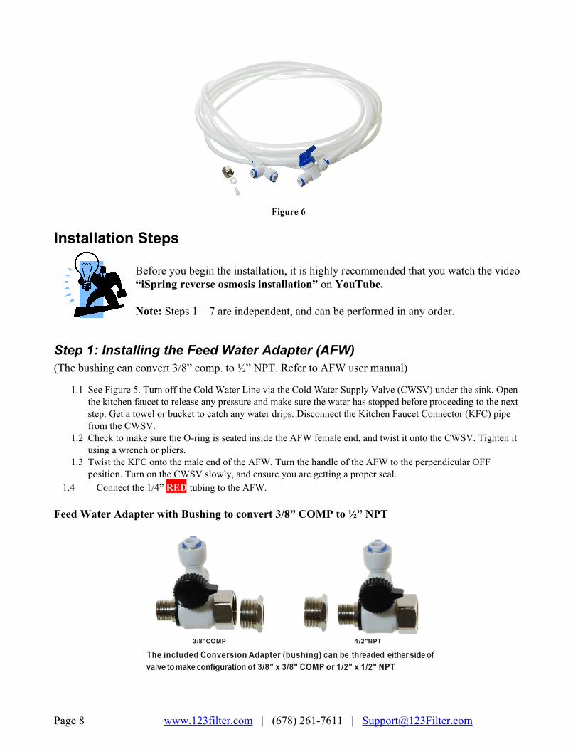
Figure 6
Installation Steps Before you begin the installation, it is highly recommended that you watch the video “iSpring reverse osmosis installation” on YouTube. Note: Steps 1 – 7 are independent, and can be performed in any order.
Step 1: Installing the Feed Water Adapter (AFW) (The bushing can convert 3/8” comp. to ½” NPT. Refer to AFW user manual)
1.1 See Figure 5. Turn off the Cold Water Line via the Cold Water Supply Valve (CWSV) under the sink. Open the kitchen faucet to release any pressure and make sure the water has stopped before proceeding to the next step. Get a towel or bucket to catch any water drips. Disconnect the Kitchen Faucet Connector (KFC) pipe from the CWSV.
1.2 Check to make sure the Oring is seated inside the AFW female end, and twist it onto the CWSV. Tighten it using a wrench or pliers.
1.3 Twist the KFC onto the male end of the AFW. Turn the handle of the AFW to the perpendicular OFF position. Turn on the CWSV slowly, and ensure you are getting a proper seal.
1.4 Connect the 1/4” RED tubing to the AFW. Feed Water Adapter with Bushing to convert 3/8” COMP to ½” NPT
Page 8 www.123filter.com | (678) 2617611 | [email protected]

Step 2: Installing the RO 2.1 If your kitchen sink does not have an existing ½” faucet hole, you will have to drill one. (Refer to How to
drill a Hole on Sink or Countertop). Wipe clean and dry the area. 2.2 Slip the front plate on the faucet stem, followed by the rubber washer. Insert the faucet stem into the hole on
the countertop. Under the sink, slip on the back rubber washer, and tighten the nut with the plastic wing. 2.3 Screw the tubing adapter onto the faucet stem. Insert the BLUE tubing about 1/2 inch into the Pushin fitting.
Step 3:
Installing the Drain Saddle 3.1 Choose a spot on the drain pipe that is convenient for
installing the drain saddle and tubing. A horizontal pipe is recommended to minimize the dripping sound.
3.2 Drill a 1 /4” hole in the drain pipe, and paste the black sticky pad around the hole. 3.3 Cut the BLACK tubing end to make a 45 degree angle. Slip the plastic nut and front plate on
the tubing. Insert the tubing into the 1 / 4” hole in the drain pipe, install the back plate, and tighten the two screws with hex nuts while the tubing remains in the hole.
3.4 Tighten the nut on the Drain Saddle by hand. Pull the tubing lightly to make sure it is secure.
Page 9 www.123filter.com | (678) 2617611 | [email protected]

Step 4: Installing the Vertical Filters: Stages 1, 2, and 3 4.1 Make sure the Oring is seated inside the groove on
top of the filter housing. (Figure 10). A light amount of foodgrade silicon jelly may be used to help the Oring seal better, but is not required.
4.2 The filter cartridges are preserved in shrink wrap. Note the direction sign on the sticker before removing the wrap (GAC stage).
4.3 When placing the filter cartridge into its housing, make sure it is centered and the knob protruding from the bottom of the housing fits in the central hole of the filter.
4.4 Screw the housing, with filters attached, onto the housing caps (caps are preassembled on the machine head). The cap also has a center knob which should be inserted into the center hole of the filter cartridge. Twist the housing on in a clockwise direction by hand, and then use the housing wrench to tighten it another 1/4 – 1/2 of a turn. Do not over tighten. This can cause leaks and make it difficult to unscrew the housing when replacing filters.
4.5 Follow steps 1.1 – 1.4 to install the GAC and CTO filters. *Note* The second stage GAC is the only filter that must go in a certain direction. Make sure the end with the rubber washer faces up, thereby attaching it to the housing cap.
Step 5: Installing the Tank Shutoff Valve (TSV) 5.1 Wrap 10 15 wraps of Teflon tape clockwise (when looking from above) onto the metal thread
at the top of the tank. 5.2 Screw (clockwise) the Tank Shutoff Valve on and tighten it by hand. Do not over tighten. 5.3 Connect the YELLOW tubing into the QuickFitting on the TSV.
Step 6: Installing the Reverse Osmosis Membrane
Figure 8 Figure 9
6.1 First, disconnect the white tube from the quickfitting connection on the membrane cap. This will allow you to unscrew the membrane housing cap.
6.2 Unscrew (counter clockwise) and remove the membrane cap. 6.3 Remove the membrane from the vacuum sealed packaging. Following the flow direction sign
on the membrane, firmly insert it into the housing. The side with the two small black Orings should be inserted first. When it is inserted fully and properly, the end of the membrane will be even with the housing opening. See Figure 89.
Page 10 www.123filter.com | (678) 2617611 | [email protected]

6.4 **Before twisting the housing cap back on, make sure the Oring is seated at the end of the membrane housing as shown in figures 8 and 9. This is very important to avoid leaking and damage to the Oring.
6.5 Place the membrane housing cap back on and hand tighten it, then use the housing wrench to tighten it another ¼½ of a turn. Do not over tighten.
6.6 **DO NOT reconnect the tubing to the fitting on the cap at this point (will be done in system start up).
Step 7: Tubing Hook Up (model specific substeps are marked with * )
7.1 See figure Sample Installation and figures of system top view, and note connection points AB, CD, EF, and GH.
Page 11 www.123filter.com | (678) 2617611 | [email protected]
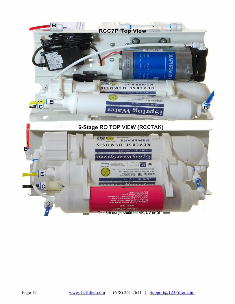

7.2 Facing the front of the system, 1st stage is the see through housing located on the right hand side. Connect the RED tubing Feed Water Adapter (AFW) (point A) to the stage 1 elbow fitting (point B).
7.3 Connect the Flow Restrictor (point C, 3inch long cylinder with a FLOW labeled on it) to the Drain Saddle (point D) with the BLACK tubing.
7.4 On the right side of the Post Carbon Filter (FT15, 5th stage), connect the Tfitting (point E) and the Tank Valve (point F) with the YELLOW tubing.
7.5 * Models without UV/AK/DI (5 stage systems): At the left end of the stage 5 FT15 filter, insert the BLUE tubing (links to RO faucet) into the elbow fitting.
Page 13 www.123filter.com | (678) 2617611 | [email protected]
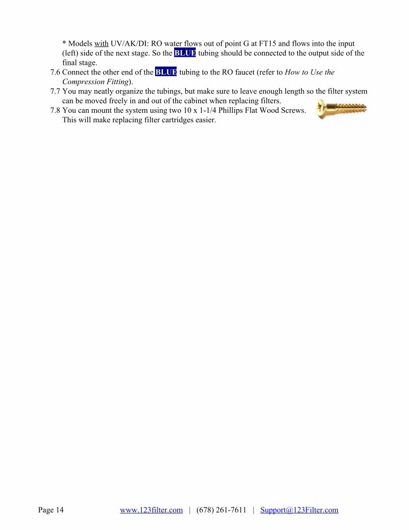
* Models with UV/AK/DI: RO water flows out of point G at FT15 and flows into the input (left) side of the next stage. So the BLUE tubing should be connected to the output side of the final stage.
7.6 Connect the other end of the BLUE tubing to the RO faucet (refer to How to Use the Compression Fitting).
7.7 You may neatly organize the tubings, but make sure to leave enough length so the filter system can be moved freely in and out of the cabinet when replacing filters.
7.8 You can mount the system using two 10 x 11/4 Phillips Flat Wood Screws. This will make replacing filter cartridges easier.
Page 14 www.123filter.com | (678) 2617611 | [email protected]

Step 8: System Start Up (model specific substeps are marked with a * ) * If your model has a UV stage, do not plug in the power until the system has been fully flushed * 8.1 Make sure no tubings are kinked. Turn the Tank Shutoff Valve OFF (perpendicular to the
yellow tube). Place a towel under the system to catch any possible water leaks. 8.2 To prevent any residual carbon from the carbon pre filters from getting into the RO membrane,
you previously left the tubing to the inlet of the RO membrane housing cap disconnected. Open the Feed Water Adapter Valve (AFW) and Cold Water Supply Valve (CWSV), and flush the first three stages into a bucket until the water turns clear.
8.3 Once the water is clear, shut off the AFW and reconnect the tubing to the RO membrane housing cap. You will want to flush the system like this whenever the first three stages are changed.
8.4 Open the RO faucet. Slowly open the AFW back up and check for any leaks. The top 3 causes of leaks are 1) The tubing is not fully inserted into the quickconnect fitting. 2) The Oring is not in the correct place or is kinked. 3) The Housing/Cap is not tightened properly or misaligned with the threads.
8.5 * After confirming that there are no leaks, plug in the booster pump power supply if your model has a booster pump.
8.6 Within 5 minutes, RO water will start slowly trickling from the faucet. Let the faucet trickle for at least 15 minutes to flush out the entire system apart from the tank. The water may appear black due to loose carbon from new carbon filters. It will eventually turn clear apart from many tiny air bubbles leaving the system.
8.7 Shut off the RO Drinking Faucet. Turn on the Tank Shutoff Valve. Wait for the tank to fill up completely. It will take 1.5 to 2.5 hours depending on your water temperature (40F100F, the warmer the faster), water TDS (up to 750, the lower the faster), and incoming water psi (35 80, the higher the faster).
8.8 After the tank is full, open the RO Drinking Faucet to drain the tank completely. Do not use the first tank of water. Let it drain into the sink until the stream turns back to a trickle this means the tank has emptied and you can close the RO faucet to let it begin filling again.
8.9 * If your system has a UV filter, plug in the UV power and check to make sure the UV light is turning on when water flows through it. The UV filter has a Flow Sensor Switch that detects water flow and only turns the light on when needed.
8.10 The TDS (total dissolved solids) of the water should be tested periodically to verify that the system is performing properly. iSpring RO systems have earned WQA GOLD SEAL by exceeding NSF/ANSI standard 58 and should be giving a 90%+ TDS rejection rate, so if your tap water is 100ppm you should be getting 10ppm or less from the RO water (200/20>, 400/40> etc.). TDS is measured with a TDS meter it is an inexpensive, easy to use device that can be found on Amazon.com or 123filter.com by searching “TDS3”.
8.11 Check for leaks daily for the first two weeks after installation to ensure the system is functioning properly. Install the included Flood Alarm to provide additional peace of mind and protection.
Page 15 www.123filter.com | (678) 2617611 | [email protected]

Congratulations, you have successfully installed your iSpring Reverse Osmosis Water Filtration System!
Start enjoying fantastic reverse osmosis water right from your tap!
End of Installation Section
Page 16 www.123filter.com | (678) 2617611 | [email protected]

ISPRING RO SYSTEM MAINTENANCE All iSpring RO systems are designed with ease of use and low maintenance in mind. If the filter cartridges are changed on schedule as suggested below, the system will work properly for years to come.
Note: Stages 6 and/or 7 only exist on certain models. To order replacement filters for your system, visit
123Filter.com and search your system’s model number.
Stage 1 – 3 PreFilters Replace every 6 months, or sooner if you notice a decrease in water flow or quality. The replacement frequency depends on your water usage and source water quality. To protect the RO membrane from chlorine and other damaging contaminants, it is important to change the prefilters according to schedule. How to change the stage 1 – 3 prefilters:
1. Shut off the cold water supply valve and tank valve, and open the RO faucet to depressurize the system. Place a bucket or towel under the system to catch any water spills.
2. If there is enough room under the sink and the filter system is hung on the wall, you can twist the filter housing off without removing the system from the wall. Otherwise, you will need to pull the system out, lay it down, and remove the housings at that point. Be careful with the tubing connections when removing the system.
3. Twist off the filter housings in a counterclockwise direction using the filter housing wrench. 4. Refer to Installation Step 1.1 to install the new vertical filter cartridges, and tighten the filter
housings back on. Remember not to over tighten them or they will be hard to unscrew next time.
Stage 4 RO Membrane: Replace every 2 – 3 years or sooner if the TDS level starts increasing.
Page 17 www.123filter.com | (678) 2617611 | [email protected]

Check the TDS level at least once a month to monitor the system’s performance. The TDS rejection rate should be 90%+. To calculate the rejection rate, divide the RO water TDS into your tap water TDS and subtract from 1. For example, 20 (RO TDS) / 200 (Tap water TDS) = 0.1 10.1 = 0.9 so the TDS rejection rate would be 90%. (NSF/ASIN STANDARD 58 for RO water filter). How to Change the Reverse Osmosis Membrane
Figure 11
Figure 12 1. The RO membrane typically lasts about 2 – 3 years. The membrane life span depends on the
source water quality, your water usage, and how often the three prefilters are replaced. To ensure the system’s performance and water purity, it is important to replace the prefilter cartridges on schedule. Use a TDS meter to periodically to check the RO water purity.
2. Shut off the cold water supply valve and tank valve, and open the RO faucet to depressurize the system. Place a bucket or towel under the system to catch any water spills.
3. Remove the tubing from the quickconnect fitting on the membrane housing cap. Use the membrane housing wrench to twist off the housing cap in a counterclockwise direction.
4. Pull out the old membrane. Use scissors or pliers to apply leverage if necessary. 5. Clean the membrane housing using hot water and scentfree dish soap (optional). Rinse
thoroughly. 6. Cut open the small end of the vacuum sealed packaging containing the new RO membrane.
Hold the new membrane through the packaging, and insert it into the housing without touching the membane with your bare hands to avoid contamination of the membrane.
7. Make sure the Oring is properly seated on the end of the membrane housing as shown in the previous images. We recommend replacing the Oring every 3 years to prevent leaking due to an expired or dried out Oring.
8. Place the membrane housing cap back on and hand tighten it, then use the housing wrench to tighten it another ¼½ of a turn. Do not over tighten.
Stage 5 FT15 Inline Post Carbon Filter and Stage 6 Inline Alkaline Filter (if your system has one): Replace the FT15 every 12 months and the Alkaline filter every 6 months
1. Remove all quickconnect tubing connections from the FT15 Post Carbon Filter. 2. Unscrew the fittings from both ends of the old Post Carbon Filter. Wrap the thread of each fitting 23 times
with Teflon tape, and screw them into their respective sides on the new Post Carbon Filter. 3. Reconnect the quick connect tubing connections to the new Post Carbon Filter.
PreFilter and Membrane Housing ORings: Replace every 3 years To prevent possible leaking due to an expired Oring. The package comes with 3 spare Orings for the prefilter housings, and 1 spare Oring for the membrane housing. Save them with this manual for future use.
Page 18 www.123filter.com | (678) 2617611 | [email protected]
Extra Installation
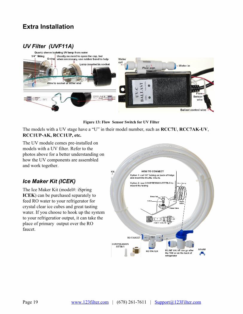
UV Filter (UVF11A)
Figure 13: Flow Sensor Switch for UV Filter
The models with a UV stage have a “U” in their model number, such as RCC7U, RCC7AKUV, RCC1UPAK, RCC1UP, etc. The UV module comes preinstalled on models with a UV filter. Refer to the photos above for a better understanding on how the UV components are assembled and work together.
Ice Maker Kit (ICEK) The Ice Maker Kit (model#: iSpring ICEK) can be purchased separately to feed RO water to your refrigerator for crystal clear ice cubes and great tasting water. If you choose to hook up the system to your refrigeratior output, it can take the place of primary output over the RO faucet.
Page 19 www.123filter.com | (678) 2617611 | [email protected]

OWNER’S MANUAL Please read this manual for useful reverse osmosis system maintenance information.
Section 1: Knowledge Base
What Is Reverse Osmosis? Reverse osmosis, also known as hyper filtration, is a membrane filtration process that separates undesirable contaminants from water by using pressure to force the water molecules through a semipermeable membrane. This process is called "reverse" osmosis because the pressure forces the water to flow in the reverse direction (from the concentrated solution to the dilute solution) to the flow direction (from the dilute to the concentrated) in the process of natural osmosis. Reverse osmosis is used to purify water and remove salts and other impurities in order to improve the color, taste, odor and/or properties of your water. RO filtration can remove up to 99% of most contaminants including arsenic, nitrates, radium, chromium, fluoride, and dissolved solids such as sodium, calcium, iron, magnesium, copper, etc.
How Effective Is Reverse Osmosis Filtration? Reverse osmosis filtration is by far the most effective and economic method of water filtration. It filters water by squeezing water through a semipermeable membrane, which is rated at 0.0001 micron (equal to 0.00000004 inch). This is the same technology used to make bottled drinking water. It is also the most used technology for desalinating seawater, making it into drinking water.
What are the specific contaminants that a reverse osmosis system removes? iSpring Reverse Osmosis filtration systems reject a wide variety of impurities. Here is a partial list: Item Rejection Rate Item Rejection Rate Item Rejection Rate Aluminum 9798% Ferro cyanide 9899% Proteins 90+% Amoebic Cysts 99% Fluoride 9496% Protozoa 99% Ammonium 8595% Giardia 99% Pyrogen 99+% Arsenic 9496% Hardness 9397% Radioactivity 9598% Asbestos 99% Herbicides 97% Radium 97% Bacteria 99+% Hydrocarbons 90+% Sediment 99% Barium 9098% Insecticides 97% Selenium 97% Bicarbonate 9596% Iron 9899% Silica 8590% Boron 5070% Lead 9698% Silicate 9597% Bromide 9396% Magnesium 9698% Silver 9597% Cadmium 9698% Manganese 9698% Sodium 9298% Calcium 9698% Mercury 9698% Strontium 9095% Chloride 9495% Nickel 9799% Sulfur/Sulfate 9798% Chromate 9098% Nitrate 9396% Sulphite 9698% Chromium 9698% PCBs 97% TDS 9599% Copper 9799% Pesticides 90+% THMs 90+% Cryptosporidium 99% Phosphate 99+% Trichlorethylene 90+% Cyanide 9095% Polyphosphate 9899% Virus 99+% Detergents 97% Potassium 9297% Zinc 9899%
Page 20 www.123filter.com | (678) 2617611 | [email protected]

Note: You may or may not have these contaminants in your water. The percentage rejection rate is for reference only. Percentages may vary since water chemistry varies in each water supply.
Does Reverse Osmosis remove pharmaceuticals from water? Yes, the 5stage RO with carbon pre filters can remove most of pharmaceuticals from water. An activated carbon filter gives these contaminants a charge so they are absorbed and removed.
Will a reverse osmosis water system taste as good as the water I pay $5.00 a bottle for? Yes! Sometimes better, depending how well the bottled water company is maintaining their purification equipment. Reverse Osmosis is the same process used by most major bottled water companies. Even some companies that use "spring water" still use Reverse Osmosis to ensure purity.
I have heard that reverse osmosis wastes a lot of water! It wastes a little but not a lot. On average, these systems will use less than 2% of your home's total water consumption. In addition, all of our Reverse Osmosis Systems use automatic shut off valves, immediately stopping the drain when the tank is full. The ratio of drain water to RO water is 2:13:1 for all of our RO systems. For a regular residential household, the waste water per day averages to about two to three flushes of the toilet.
What is an Alkaline Filter? The Alkaline filter changes the acidic RO water into a perfect Natural Alkali Calcium Ionized Water. The Alkaline filter simply gives back minerals such as ionized calcium, magnesium, sodium, potassium ion, which were taken away while purifying the water.
● Produces pHbalanced alkaline water, helps minimize the fluctuations of your body's pH.
● Turns acidic drinking water into alkali calcium ion water. ● The natural calcium, magnesium, sodium, and potassium ions can be absorbed 100% by the
body. ● These minerals are easily absorbed by the body because they have structurally smaller
molecules which help the body take in more water and replenish lost water quicker. ● Makes the water cleaner and healthier. ● Improves the qualities of RO water by adding necessary minerals for proper human
development, such as calcium, magnesium, sodium, potassium, and others readily found in many natural mineral waters.
● Mainly installed with RO systems to complement their absolute filtration qualities.
Page 21 www.123filter.com | (678) 2617611 | [email protected]

What is a DI filter? DI stands for deionization. The DI filter takes reverse osmosis to a higher level of filtration. It is an excellent inline filter, especially for those who live in areas with exceptionally high levels of total dissolved solids (TDS) in their tap water. The DI filter takes the small percentage of contaminants that the membrane could not remove and filters the water to 99.99% purity, and give you close to 0 ppm TDS. Conductivity attainable less than 0.1uS/cm or resistivety of close to 18 meg.ohm.
What is a UV filter? Our UV filter comes with an 11W UV sterilization lamp in a stainless still housing. The UV kills 99% of viruses and bacteria in the water. The UV light has wavelengths between 250 and 270 nanometers (UVC or UVC band) and is extremely effective in killing many species of bacteria, mold spores, viruses and other microorganisms. It is recommended for customers who use well water, rain water, or have bacteria concerns in their water.
What is a TDS meter? A TDS meter is a handheld Total Dissolved Solids tester. TDS is the total weight of all solids dissolved in a given volume of water. It is expressed in parts per million (PPM). With a TDS meter, you can compare the quality of the RO water with your original source water, and also periodically check the RO water to know when it’s time to change the filters.
Maximum distance from tank to faucet We recommend staying under a total distance of 15 feet of tubing between the tank and the RO faucet or output location. The system will produce a faster flow at the faucet with the shortest tubing run from tank to faucet.
What is an ASOV and what does it do? The ASOV is the automatic shutoff valve. This valve allows the system to turn off the water supply using pressure from the pure water side of the system. The ASOV is a critical piece to the system as it saves water, extends filter life, and improves the performance of the unit. As the storage tank fills, the tank pressure increases. When the tank fills completely, a pressure signal is sent to the ASOV, and the water supply to the system is shut off.
Page 22 www.123filter.com | (678) 2617611 | [email protected]

Does the UV filter run 24/7? Will the water out of UV filter be hot? The iSpring UV filter features a Smart Flow Sensor Switch that automatically turns the UV filter on and off by water flow. The UV stays off until the RO faucet is opened, which will then switch the UV filter on via water flow. So the UV filter only runs when needed, and does not heat the water either.
How does your RCS5T tankless RO system compare to the GE Merlin 700GPD system? Our tankless RCS5T RO system is a complete 5stage filtration system, with 3 pre filters (Sediment, GAC, and CTO), SideFlow® membrane, and post carbon filter, while the GE Merlin 700GPD has only one prefilter (either sediment or carbon), two membranes, and 1 post filter. Therefore, the GE Merlin is used in light commercial applications where a separate prefilter system or backwashing carbon filter system will be required. Furthermore, our tankless RCS5T RO system utilizes patented SideFlow membrane technology, delivering a waste ratio equal to or less than 1:1, compared to 3:1 in other systems.
Page 23 www.123filter.com | (678) 2617611 | [email protected]

Section 2: Troubleshooting Guide
Leaking from where the tubing is pushed into the quickconnect fitting It is very likely that the tube is not fully inserted into the fitting. If you remove the tube and look inside the elbow fitting, you will see a small black O ring. If the tube is not pushed past this O ring, no seal will be created. To make sure you are getting the tubes pushed in past the O ring, make a ½” mark on the end of the tube. When inserted properly, the tube will be inserted to this mark. You will get resistance when you reach the O ring initially, but wiggle the tube and use extra pressure to get it past the O ring. You will feel it go in further when you do so. Once the tube is in all the way, re insert the blue clip on the elbow fitting. If this does not fix the problem, switch out the elbow fitting for one of the extras that came with the system. Before replacing, wrap the new fitting thread 23 times with Teflon tape to ensure a proper seal.
Leaking around filter housing (Oring is too small or is not in place) Please check to make sure all of the filter cartridges are sitting upright inside the canisters. Then, ensure the Oring is properly in place. The Orings may be a little too small, please stretch it out and put it back inside the groove. You may overstretch a little so when it is back in the canister, it will shrink and fit just right. Then insert the cartridge to the top cap, and screw the canister all the way up. MAKE SURE ORINGS are staying in place during this process. Then use a wrench to tighten (no need to over tighten it). If the membrane housing is leaking, please make sure the Oring is seated correctly as shown in the manual. It should be seated on the end of the membrane housing before the threads begin. When in the correct place, there will not be any pressure or tension on the Oring.
Low water pressure at the RO faucet or output location ● Have you given the system enough time to fill up the tank? If you just installed the system, give
it 1.52 hours to fill the tank. ● What is the total distance between the tank and the output location? If it is over 15 feet or going
vertically, the pressurized tank is struggling to push out the water at an adequate pace. Shorten the distance beetween the tank and output location, or add a delivery/demand pump to assist with the output. Do not confuse this with a Booster Pump which is only for raising the INPUT pressure.
● The stage 5 Post Carbon Filter is clogged and needs to be replaced. ● If you are dispensing the RO water through your refrigerator, remove the filter that is currently
installed in your fridge. ● What is the incoming water PSI to your home? If it is below 45 PSI, we recommend getting a
system with a booster pump so the reverse osmosis process can be performed correctly. If you water pressure is below 45 PSI, there will not be enough water pressure to push the water through the RO membrane on a continous basis.
● Incorrect air pressure in the tank. Shut off the main water supply to the system, and open the faucet to drain the tank. After the faucet stops dripping, close the tank valve, remove the connected yellow tube, and take the tank outside or somewhere that can get wet. Remove the tank valve from the top of the tank, and turn it upside down to drain out any remaining water. Then, use a standard tire pressure gauge to check the air pressure at the nozzle on the bottom half of the tank. The air nozzle is under a screw off blue cap. If the pressure is not between 710
Page 24 www.123filter.com | (678) 2617611 | [email protected]

PSI, use a bicycle pump to get the air pressure within that range and reconnect the tank to the system.
● If the tank feels full and no water is coming from the faucet, the tank bladder could be broken. You can verify this by measuring the tank’s PSI and it being zero.
Little water from the RO faucet Tank is heavy and appears full of water, but the stream turns very weak after a few seconds. If there is no change in the supply water pressure, the problem is very likely from the tank. It could be due to low tank pressure or broken bladder. Perform the following steps first.
1. Shut off main water supply 2. Get a bucket under the tank and remove tank by disconnecting the ball valve. 3. Dump the water from the tank by turning it upside down (through the top stem). You may add
air from the front valve to help emptying the water. 4. Use a gauge at the front air valve to check tank pressure. It should be within 710 PSI. If too
low, you can use a bicycle pump to add more pressure to the tank. 5. Reconnect tank to the system and turn on the water supply.
Continuous Drain All RO systems require drain water. The drain water should run only when the system is producing water. The ratio of drain water to RO water is about 2:13:1 for our residential RO systems (SideFlow systems have a lower 1:1 ratio). The drain should stop after the tank is full. Allow 3 hours to ensure the tank has been filled completely. If the drain is still running, try the following to determine the cause:
● What is your incoming water pressure? If it is below 45 PSI, this is likely the cause of the continous drain. When there is not enough water pressure to force the water through the RO membrane, most or all of the water will go to the drain. Because the water is unable to get through the RO membrane, the tank never fills up, and never triggers the system to cut off the water supply.
● Close the tank valve and wait 20 minutes. After 20 minutes, remove the black drain line from the drain pipe to see if it has stopped draining continously. If it has stopped, we will know the continous drain has something to do with the tank, and you will want to follow the directions below to check the air pressure in the tank. If it has not stopped, we will know it has something to do with the system, likely the automatic shutoff valve (ASOV) or check valve (the check valve is the elbow fitting at the pure water outlet of the membrane housing).
● If the continous drain stopped after you closed the tank valve, you will want to measure the air pressure in the tank. Shut off the main water supply to the system, and open the faucet to drain the tank. After the faucet stops dripping, close the tank valve, remove the connected yellow tube, and take the tank outside or somewhere that can get wet. Remove the tank valve from the top of the tank, and turn it upside down to drain out any remaining water. Then, use a standard tire pressure gauge to check the air pressure at the nozzle on the bottom half of the tank. The air nozzle is under a screw off blue cap. If the pressure is not between 710 PSI, use a bicycle pump to get the air pressure within that range and reconnect the tank to the system.
Page 25 www.123filter.com | (678) 2617611 | [email protected]

High TDS level in RO water The RO system should produce a TDS rejection rate of about 8595%. If it is not, check the following:
● How long have you had the current filters installed for? Check the filter change times to make sure no filters (especially the membrane) are expiring and causing the TDS increase.
● What is tap water TDS reading? Is there a sudden increase in tap water TDS level? ● Has the RO membrane been installed into the membrane housing? It is a long blue filter packed
in a vacuum sealed plastic bag, and located in the accessories box. ● Are the drain and pure RO water lines reversed? Compare your tubing connections to the
diagram on the manual to double check. ● The automatic shutoff valve (ASOV) could be getting stuck open and mixing the tap and pure
RO water. This is typically, but not always, accompanied by continous drain water.
Tastes and Odors in Product Water Possible Cause Solution
Carbon Post Filter is exhausted. Replace Filter. There is foreign matter in Holding Tank. Clean, flush and sanitize the Holding Tank.. Replace filters. Product water and Drain water lines are reversed. Correct plumbing. Dissolved gases in feed water. Pretreat feed water to remove gasses. Increase in Product Water TDS. See High TDS in Product Water Section
Faucet Leaks or Drips Adjust the faucet by turning the tee bar located under the handle to provide a small amount of free play in the handle when shut off. Should this not work, repair or replace the faucet.
Cloudy Water and Ice Cubes If you just installed the system, you are very likely seeing many tiny air bubbles in the water. During the first week or two after installing the system or changing filters, the system will be clearing itself of every nook and cranny of trapped air.
After installation, the water out of the RO faucet is only a trickle Reverse osmosis is a very slow process. The pressurized tank is included so the RO water can be produced over a couple hours, and then be readily available when you open the RO faucet. After installation, you will need to let the tank fill for 1.52 hours before seeing a steady stream from the faucet.
Sudden drop in RO water production There are a few potential factors causing the problem.
● Feed water valve is plugged or closed.
● Sediment/Carbon prefilters or Post Carbon Filter is clogged.
Page 26 www.123filter.com | (678) 2617611 | [email protected]

● Low incoming water pressure. ● Reverse Osmosis Membrane is fouled. ● Air pressure in the holding tank is incorrect. ● Air bladder in the holding tank is ruptured. ● Holding tank valve is closed. ● No water to drain. Drain Flow Restrictor is clogged. ● The Check Valve on the RO Membrane housing is faulty. ● The Automatic ShutOff Valve (ASOV) is malfunctioning.
Page 27 www.123filter.com | (678) 2617611 | [email protected]

Warranty This Limited Warranty extends to the original purchaser of the system only. This warranty covers all Manufacturersupplied items only that prove to be defective in material, workmanship, or factory preparation. This warranty covers parts only; all labor is excluded from this warranty, including, but not limited to, services related to the removal, replacement, installation, adjustment, maintenance, and/or repair of the unit or its components items. excludes all nonManufacturer labor required for any servicing of the unit, including, but not limited to, servicing related to installation, adjustment, maintenance, and repair of the unit. This warranty applies only for the first full calendar year from date of purchase. The following items are excluded from this warranty: membranes, filters, Orings, and all other parts or components that require regular replacement as a result of ordinary usage. Disclaimers: This Limited Warranty applies only if the system is installed, used, and maintained in compliance with all instructions and requirements enclosed with the system. This warranty will be void for failure to observe the following conditions: 1. The system is to be used with potable water supply only. 2. Feed water pressure to the unit is no less than 40 PSI (30 PSI for systems with builtin booster pump) and no greater than 80 PSI. 3. The system is to be used on water supplies with chlorine concentrations of 1.0 mg/L (ppm) or less. 4. Feed water temperature to the unit must be no less than 40°F and no more than 100°F. 5. Total dissolved solids (TDS) in feed water must be less than 750 mg/L (ppm). 6. Feed water must have a pH between 4 and 8. 7. Turbidity must be less than 1.0 NTU. 8. SDI must be less than 5. 9. Feed water must be completely free of iron, manganese or hydrogen sulfide. While the testing was performed under standard laboratory conditions, actual performance may vary. The Manufacturer does not know the characteristics of your water supply. The quality of water supplies may vary seasonably or over a period of time. Your water usage may vary as well. Water characteristics can also change if the drinking water appliance is moved to a new location. The Manufacturer assumes no liability for the determination of the proper equipment necessary to meet your requirements, and we do not authorize others to assume such obligation on our behalf. This Limited Warranty does not cover any Manufacturersupplied items that are defective as a result of the use of improper parts, equipment or materials. This warranty does not cover alterations or modifications of the unit or failure of a unit caused by such alterations and modifications. This Limited Warranty does not cover malfunctions of the unit due to tampering, misuse, alteration, lack of regular maintenance, misapplication, fouling due to hydrogen sulfide, manganese or iron, scaling from excessive hardness, turbidity greater than 1.0 NTU, Silt Density Index (SDI) greater than 5.0 SDI, or excessive membrane hydrolysis due to chlorine levels in excess of 1.0 mg/L (ppm). In addition, damage to the unit due to fire, accident, negligence, act of God, or events beyond the control of the Manufacturer are not covered by this warranty. Incidental and Consequential Damages Limitation: The Manufacturer will not be responsible for any incidental or consequential damages as a result of the failure of this unit to comply with express or implied warranties or any defect in the unit, including but not limited to, lost time, inconvenience, damage to personal property, loss of revenue, commercial losses, postage, travel, telephone expenditures, or other losses of this nature. In case some states do not allow the exclusion or limitation of incidental or consequential damages, you may choose to return the system. If you choose to keep it, you insist this exclusion STILL apply to you. Owner’s Warranty Responsibilities: As a condition of this Limited Warranty, the owner must ensure that periodic maintenance of the system is performed as described in the literature enclosed with the system. Neglect, improper maintenance, abuse, modification, or alteration of the unit will invalidate this Warranty. Should your unit develop a defect or otherwise fail to perform in accordance with this warranty, you should contact the retailer from whom the product was originally purchased. Implied Warranties: The implied atlaw warranties of merchantability and fitness for a particular purpose shall terminate on the date one year after the date of purchase. NOTE: IN CASE SOME STATES DO NOT ALLOW LIMITATIONS ON HOW LONG AN IMPLIED WARRANTY LASTS, YOU MAY CHOOSE TO RETURN THE SYSTEM. IF YOU CHOOSE TO KEEP IT, YOU AGREE THAT THE ABOVE LIMITATIONS STILL APPLY TO YOU.
Page 28 www.123filter.com | (678) 2617611 | [email protected]

Warranty Registration We provide a 30day money back guarantee, a 1 year manufacturer warranty, and lifetime tech support for all of our products. However, we do not have the order information from vendors other than 123Filter.com (Amazon, Home Depot, etc.), so please be sure to fill in that information upon registration of your system. To register your product for the warranty, please visit our website at 123filter.com and go to the “Warranty Registration” tab. If you have any questions or concerns about your product, please do not hesitate to call or email us, or put it in the notes/comments upon your warranty registration. Your satisfaction is our business! If you are happy with our products and service, we would truly appreciate you leaving a review for your product on Amazon.com, Homedepot.com, or whichever vendor you purchased from. We sell exclusively online, and customer feedback helps us stay in business and continue supplying replacement filter cartridges at factory direct prices. Thank you and enjoy your system!
iSpring Warranty Registration Your Name:
Your EMail:
Your Phone:
Order#:
Model#:
Order Date:
Reviewer ID:
Notes:
Please remember, we love to help our customers. If you have any questions or concerns about our products, please don’t hesitate to call or email us. We will do all we can to make your purchase a 5star experience. If you are happy with our product and service, please show your support by writing a product review on Amazon, even with a single line. It takes you just a minute, but means a lot to us. Thank you! How To Contact Us
Office Hours: MondayFriday 9:00 a.m. 5 p.m. EST
Page 29 www.123filter.com | (678) 2617611 | [email protected]

3020 Trotters Parkway Alpharetta, GA 30004, USA
For technical support, please contact us at:
[email protected] 16782617611
Page 30 www.123filter.com | (678) 2617611 | [email protected]