issn - ijcrar and t. warmate.pdf · issn: 16 introduction the geotechnical evaluation of subsoil...
TRANSCRIPT

16
Introduction
The geotechnical evaluation of subsoil condition of a site is necessary in generating relevant data inputs for the design and construction of foundations for proposed structures (Nwankwoala & Warmate, 2014). Sub-soil geotechnical data
are required for proper design and construction of civil engineering structures to prevent adverse environmental impact or structural failure/prevention of post construction problems ((Oghenero et al, 2014; Ngah & Nwankwoala, 2013). This is
ISSN: 2347-3215 Volume 2 Number 4 (April-2014) pp. 16-25 www.ijcrar.com
A B S T R A C T
The study establishes the sub-soil types and profile to ascertain the geotechnical characteristics of the underlying soils in Okochiri, Okrika, Rivers State, Nigeria for appropriate foundation design considerations in the area. Borings were accomplished using a percussion rig with the aid of augers. Representative samples were analyzed in the laboratory in accordance with relevant geotechnical engineering standards. The study revealed that the topsoil is underlain by firm clay of moderate compressibility with Cu: 56-64KN/m2 (about 10m thick). Underneath this layer , is loose sandy layer with phi =28-29o (thickness 8m ) overlying a poorly sorted medium dense sand layer with Phi between 300 to 350. The drainage characteristics of the sub-soils are low. The allowable bearing capacity profile of the sub-surface shows moderate bearing Capacity characteristics (1.5m:120KN/m2). Settlement predictions based on a loading of 300KN/m2 indicated a settlement of < 100mm. Pile foundation is therefore recommended for consideration. This study therefore, has provided valuable data that can be used for foundation design and construction of future civil engineering structures in the study area.
KEYWORDS
Sub-soil, geo-technical, lithology, foundation, Okochiri
Geotechnical Evaluation of Subsoil for Foundation Design Considerations in Okochiri, Okrika Island, Rivers State, Nigeria
H.O.Nwankwoala1* and T. Warmate2
1Department of Geology, College of Natural and Applied Sciences, University of Port Harcourt, Nigeria 2Geostrat International Services Limited, No.14 Mannila Pepple Street, D-Line, Port Harcourt, Nigeria *Corresponding author

17
desirable in view of the rapid urbanization, resulting in extensive infrastructural development.
Generally, from the engineering point of view, the soils in wetlands are generally low-bearing-capacity foundation materials with the voids saturated with water with major engineering problems including: excess surface and groundwater, poor drainage, high compressibility, low bearing capacity and differential settlement, among others (Oghenero et al, 2014). Quaternary soils which are the foundation materials in the Niger Delta were deposited in a wide variety of environmental conditions with unique gemorphological features which have rendered them vertically and laterally heterogenous in form and anisotropic in engineering properties. This study determines the stratigraphy of the superficial deposit underlying the area as well as the relevant engineering characteristics of the deposits to enable appropriate foundation design of the structure.
Study Area Description
Okochiri is in Okrika Local Government Area of Rivers State, and is located within the Niger Delta Sedimentary Basin (Fig. 1). The general geology of the Niger Delta consists of various types of Quaternary deposits overlying the three major lithostratigraphic units. These are from bottom to top the Akata, Agbada and Benin Formations. The units have been extensively studied and described in literature, including the classic work of Short and Stauble (1967). The Akata Formation forms the basal unit of the Niger Delta stratigraphic sequence and consists of an open marine facies unit dominated by high-pressured carbonaceous shales. The formation ranges in age from Paleocene to
Eocene in age and its thickness could exceed 1000 meters. It is overlain by the Agbada Formation consisting of a sequence of alternating deltaic sands and shales. It is Eocene to Oligocene in age and exceeds 3000meters in thickness. This formation is oil-reservoir of the Niger Delta Basin. The overlying Benin Formation is Oligocene to Pleistocene in age and consists predominantly of fresh water continental friable sands and gravel that are of excellent aquifer properties with occasional intercalation of shales. The thickness of the formation is variable but generally exceeds 2000 meters. Geologically, the formation generally does not exceed 120 meters in thickness and it is predominantly unconfined. The Benin Formation is overlain by various types of quaternary alluvial deposit comprising mainly of Recent deltaic sand, silt and clay of varying thickness. These alluvial deposits occur in five major geomorphic units namely: Active and abandoned coastal beaches, Salt water /Mangrove swamp, Fresh water swamp, Sombreiro-Warri Deltaic plain with abundant fresh water swamps and Dry flat land and plain overly the Benin Formation. The Benin Formation constitutes the regional aquifer in the Niger Delta. Knowledge of the groundwater conditions in the Niger Delta area is obtained from the work of Etu-Efeotor and Akpokodje (1990) which delineated several irregular, lenticular and laterally discontinuous layers of clay aquitard that regionally subdivide the regional aquifers into five units. Except in most of the coastal beach islands, all the aquifers in the other geomorphic units are generally overlain by sandy/silty clay or clay at near the surface. However in the coastal beach islands, a thin surficial sand layer, 0.5-3m thick, directly overlies relatively thick clay which in turn overlies the regional aquifer resulting in perched aquifers. In the study

18
area, the aquifers occur under semi confined and unconfined conditions. The water table is very close to the ground surface and varies from 0 to 4meters. The hydraulic conductivities of the sand vary from 3.82 x 10⁻³ to 9.0 x 10⁻²cm/sec which indicates a potentially productive aquifer Offodile (1991). Specific capacities recorded from different areas within this formation vary from 6700lit/hr/m to 13,500lit/hr/m. Groundwater recharge is mainly by precipitation. The hydraulic conductivities of the sand vary from 3.82 x 10⁻³ to 9.0x10⁻²cm/sec which indicates a potentially productive aquifer. Specific capacities recorded from different areas within this formation vary from 6700lit/hr/m to 13,500lit/hr/m. The water table is very close to the ground surface and varies from 0 to 4 meters but was encountered between 2.5 and 4m below the ground surface during this study.
Methods of Study
The methods of study comprised of six (6) borings, twelve (12) Cone Penetrometer Test and Vane Shear Test at a pre-determined locations in the study area.
Cone Penetration Testing (CPT)
Hydraulically operated, GMF type, static penetrometer of 100KN capacity was used in the cone resistance soundings. Mechanical mantle cone with friction jacket was used in the operation. Discontinuous sounding procedure was adopted in the test. The cone in its retracted position is first forced into the ground a distance of 10cm by the application of force to the outer sounding tubes. The cone is then pushed out a distance of about 4cm by the application of force to the inner rods only and the magnitude of the force required to achieve
this, is measured on the pressure gauges and recorded. This is the cone resistance.
Soil Borings
Conventional boring method which consists of the use of the light shell and auger hand rig was used in the boring operation. During the boring operations, disturbed samples were regularly collected at depths of 0.75m intervals and also when change of soil type was noticed. Undisturbed cohesive soil samples were retrieved from the boreholes with conventional open-tube sampler 100mm in diameter and 450mm in length. The open-tube sampler consists essentially of a lower end and upper end screwed into a drive head which is attached to the rods of the rig. The head has an overdrive space and incorporates a non-return valve to permit the escape of air or water as the samples enters the tube. The sampler was driven into the soil by dynamic means using a drop hammer. On withdrawal of the sampler, the non-return valve assisted in retaining the sample in the tube. All samples recovered from the boreholes were examined, identified and roughly classified in the field.
Standard Penetration Tests (SPT) were performed every 1.5m advance through cohesionless soils. The main objective of this test was to assess the relative densities of the cohesionless soils penetrated. In this test, a 50mm diameter split spoon sampler was driven 450mm into the soil with a 63.5kg hammer falling freely a distance of 760mm. The sampler was driven into the soil in two stages. The initial 150mm penetration of the sampler is the seating drive and the last 300mm penetration, the test drive. The number of blows required to effect the last 300mm penetration below the seating drive provided an indication of the relative density of the cohesionless soil

19
stratum tested. This is also referred to as the N-value. The penetration resistances of blow counts with depths are indicated on the borehole logs (Fig.2).
Results and Discussion
Bearing Capacity
The bearing capacity analysis for the underlying soils is limited to the near surface sandy clay. In general, the sandy clay is partially saturated and when tested in unconsolidated and undrained conditions, exhibits both cohesion and angle of internal friction for its shear strength characteristics. However, the frictional component of shear strength is neglected for the clay encountered within normal founding depths for shallow foundations when estimating ultimate bearing pressures for the clay. Undrained cohesion of 56kPa and angle of internal friction of zero were adopted for the bearing capacity analysis. Table 1 shows the allowable bearing capacities for shallow foundations (Water depth > foundation Depth), continuous foundation.
Soil Stratigraphy
The data from the soil sampling, standard penetration tests, cone resistance soundings and laboratory tests were carefully evaluated for the determination of the stratification of the underlying soils. The evaluation uncovered two primary soil zones beneath the site. A typical soil profile characterizing the study area is described below: (i) Firm Sandy Clay (0.0-10m) (ii) Loose Dense sandy layer (10m-19m),
(iii) Medium Dense sandy layer (19m-30m)
Engineering Properties of the Soils
The study revealed that the soil deposits within the depths explored were characterized by a near-surface deposit of firm sandy clay. Underlying this layer is a loose to medium dense sandy layer. The thickness of the most compressible zone is roughly 10m. The water table was at 10.2m below ground level. Classification, strength and compressibility characteristics of the soils were determined from the laboratory and in-situ tests. The relevant index and engineering parameters of the soils are summarized below. Details of these are presented in tables at the end of this report.
Firm Clay: The thickness of this deposit, as confirmed by both the borings and the cone resistance soundings varied within 10m. The clay is mainly of moderate compressibility with Mv values >0.16m2/MN and Brownish in colour, with average CPT value of 10.0kg/cm2
.The ranges of variations in the relevant geotechnical index and engineering parameters of the clay are summarized below:
Natural moisture content (%) 14.7
Liquid limit (%) 35 Plastic limit (%) 16 Plasticity index (%)19 unit weight (kN/m3) 19.3 Undrained cohesion (kPa) 64 Angle of internal friction (o) 8

20
Table.1 Allowable Bearing Capacities for shallow foundations
(Water depth > foundation Depth)
Foundation Depth
(m)
Width (m)
Undrained Shear Strength (KN/m2)
Ultimate Bearing Pressure (KN/m2)
Allowable Bearing Pressure (KN/m2)
L/B =1 L/B= 1.5 L/B = 5 L/B=1 L/B=1.5 L/B=5
1 1 56 347.55 0 0 115.85 0.00 0.00 1 1.5 56 347.595 0 0 115.87 0.00 0.00 1 2 56 347.64 0 0 115.88 0.00 0.00 1 2.5 56 347.685 0 0 115.90 0.00 0.00 1 5 56 347.91 0 0 115.97 0.00 0.00 1 10 56 348.36 0 0 116.12 0.00 0.00
1.5 1 56 361.68 0 0 120.56 0.00 0.00 1.5 1.5 56 361.725 0 0 120.58 0.00 0.00 1.5 2 56 361.77 0 0 120.59 0.00 0.00 1.5 2.5 56 361.815 0 0 120.61 0.00 0.00 1.5 5 56 362.04 0 0 120.68 0.00 0.00 1.5 10 56 362.49 0 0 120.83 0.00 0.00
2 1 56 375.81 0 0 125.27 0.00 0.00 2 1.5 56 375.855 0 0 125.29 0.00 0.00 2 2 56 375.9 0 0 125.30 0.00 0.00 2 2.5 56 375.945 0 0 125.32 0.00 0.00 2 5 56 376.17 0 0 125.39 0.00 0.00 2 10 56 376.62 0 0 125.54 0.00 0.00
Figure.2 Typical Borehole Log and Cone Penetration Profile (CPTs of BH- 1)

21
Table.1 The ranges of variations in the relevant engineering parameters of the sand
Geotechnical properties Average Effective particle size d10 (mm) 0.23 Mean particle size d50 (mm) 0.8 Coefficient of uniformity Cu=d60 D60
5.2
Coefficient of curvature Cc= d230
D10-d60
1.08
SPT penetration resistance N values (blows/0.3m)
8
Table.2 The ranges of variations in the relevant engineering parameters of the sand
Geotechnical properties Average Effective particle size d10 (mm) 0.22 Mean particle size d50 (mm) 0.6 Coefficient of uniformity Cu=d60 D60
3.18
Coefficient of curvature Cc= d230
D10-d60
1.0
SPT penetration resistance N values (blows/0.3m)
23
Figure.3 Typical Particle Size Distribution Curve from the Study Area

22
Table.3 Triaxial Test Results for BH 1 @ 6 m
Minor Principal Stress
100KN/m2 300KN/m2
Deviator Stress
180KN/m2
248KN/m2
Major Principal Stress
280KN/m2 548KN/m2
C= 64KN/m2, Phi =8o
Table.4 Triaxial Test Results for BH 2 @ 3m
Minor Principal Stress
100KN/m2 300KN/m2
Deviator Stress
197KN/m2
280KN/m2
Major Principal Stress
297KN/m2 580KN/m2
C= 64KN/m2 , Phi =10o
Table.5 Triaxial Test Results for BH 3
Minor Principal Stress
100KN/m2 300KN/m2
Deviator Stress
208KN/m2 329KN/m2
Major Principal Stress
308KN/m2 629KN/m2
C= 60KN/m2 , Phi =13o
Table.6 Triaxial Test Results for BH 4 @ 6 m
Minor Principal Stress
100KN/m2 300KN/m2
Deviator Stress
177KN/m2
241KN/m2
Major Principal Stress
277KN/m2 541KN/m2
C= 62KN/m2 , Phi =8o
Table.7 Triaxial Test Results for BH 5 @ 3 m
Minor Principal Stress
100KN/m2 300KN/m2
Deviator Stress
200KN/m2
300KN/m2
Major Principal Stress
300KN/m2 600KN/m2
C= 63KN/m2 , Phi =11o
23
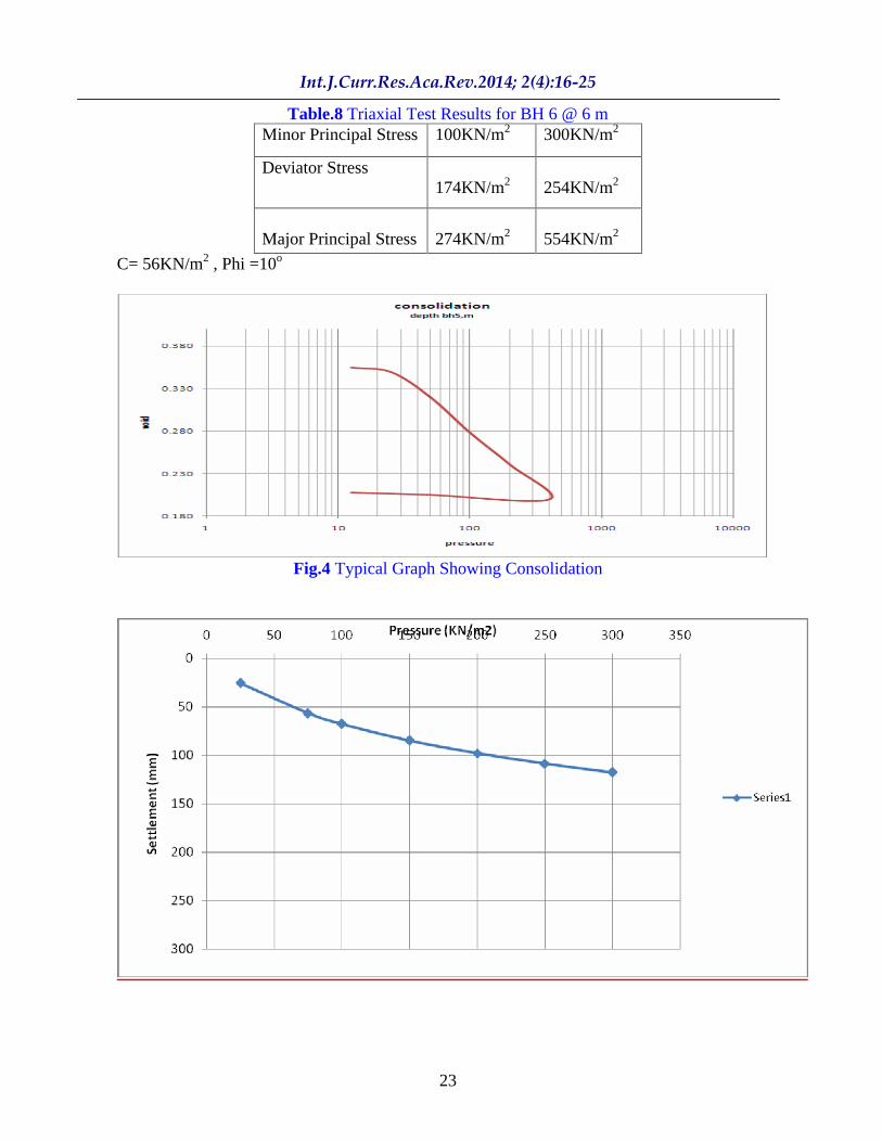
Table.8 Triaxial Test Results for BH 6 @ 6 m
Minor Principal Stress
100KN/m2 300KN/m2
Deviator Stress
174KN/m2
254KN/m2
Major Principal Stress
274KN/m2 554KN/m2
C= 56KN/m2 , Phi =10o
Fig.4 Typical Graph Showing Consolidation

24
Fig. 5 Typical Graph of Settlement Versus Foundation Pressure
Fig.6 Typical Mohr Circles of the Quick Undrained Triaxial Test for the Study Area
Loose Sand: Underlying the sandy clay is a layer of predominantly loose-sand, with about 9m of the sand deposit (Table 1). For design purposes, mean angle of internal friction of 29o and cohesion zero are suggested for the sand layer.
Medium Dense Sand: Underlying the loose sandy is a layer of predominant medium-dense sand, with about 11m of the sand deposit (Table 2).
For design purposes, mean angle of internal friction of 34o and cohesion zero are suggested for the sand layer. Fig. 3 shows the particle size distribution curves while Fig.4 shows the consolidation graph. Fig. 5 shows typical graph of settlement versus foundation pressure while Fig.6 is the typical Mohr Circle of the quick undrained triaxial test for the study area.
Conclusion
This study revealed that the topsoil is underlain by a firm clay of moderate
compressibility with Cu: 56-64KN/m2
(about 10m thick). Underneath this layer, is loose sandy layer with phi =28-29o
(thickness 8m ), overlying a poorly sorted Medium Dense Sand Layer with Phi between 300 to 350. Study also shows that the drainage characteristic of the sub-soil is low. The allowable bearing capacity profile of the sub-surface shows moderate bearing capacities characteristics (1.5m: 120KN/m2). Settlement predictions based on a loading of 300KN/m2 indicated settlements of < 100mm. Pile foundation is therefore recommended for consideration. More importantly, the study has provided valuable data that can be used for foundation design and construction of future civil engineering structures.
References
Amadi, A.N; Eze, C.J; Igwe, C.O; Okunlola, I.A and Okoye, N.O 2012. Architect s and geologist s view on the causes of building failures in Nigeria. Modern Applied Science, Vol.6 6: 31 38.

25
Annor, A.E; Olasehinde, P.I and Pal, P.C 1987.
Basement fracture patterns in the control of water channels
An example from Central
Nigeria. Paper presented at the 23rd Annual Conference of the Nigerian Mining and Geosciences Society, Benin, pp9.
British Standard Methods of Test for soils for Civil Engineering Purposes. B.S 1377: Part 2, 1990. Published by the British Standards Institution, pp 8 200.
Carter M 1983 Geotechnical Engineering Handbook, Pentech Press, 226pp
Dun,T.S, Anderson L.R. and Keifer 1980 Fundamental of Geotechnical Analysis
John Wiley Publisher , 414 pages. Etu-Efeotor, J.O and Akpokodje, E.G 1990.
Aquifer systems of the Niger Delta. J. Mining Geol. Vol.26 2, pp279-285
Lee I.K, White W and Ingles O.G 1983 Geotechnical Engineering, Pitman, 507pgs. Longman, 536 pp
Merki, J.P.1970. Structural Geology of the Cenozoic Niger Delta. African Geology. University of Ibadan Press.pp251-268
Murat, R.C 1970. Stratigraphy and Paleogeography of the Cretaceous and Lower Tertiary in Southern Nigeria. In: Dessauvagie, T.T J and Whiteman, A.J eds.. African Geology, University of Ibadan Press, Ibadan, Nigeria. Pp251
266. Murthy V.N.S 1984 Soil Mechanics and
Foundation Engineering, Dhanpart Rah and Sons , India.763pgs.
NEDECO 1961 Water of the Niger, Niger Delta Environmental Survey 1999 Physical Environment Report on the Hydrology of the Niger Delta
Ngah, S.A and Nwankwoala, H.O 2013. Evaluation of Geotechnical Properties of the Sub-soil for Shallow Foundation Design in Onne, Rivers State, Nigeria. The Journal of Engineering and Science, Vol. 2 11: 08 - 16
Nwankwoala, H.O and Amadi, A.N 2013. Geotechnical Investigation of Sub-soil and Rock Characteristics in parts of Shiroro-Muya-Chanchaga Area of Niger State, Nigeria. International Journal of Earth Sciences and Engineering, Vol.61:8 17.
Oghenero, A.E; Akpokodje, E.G and Tse, A.C 2014. Geotechnical Properties of Subsurface Soils in Warri, Western Niger Delta, Nigeria. Journal of Earth Sciences and Geotechnical Engineering, 41: 89
102
Oke, S.A and Amadi, A.N 2008. An assessment of the geotechnical properties of the sub-soil of parts of Federal University of Technology, Minna, Gidan Kwano Campus, for foundation design and construction. Journal of Science, Education and Technology, Vo.1 2:87 102
Oke, S.A; Okeke, O.E; Amadi, A.N; Onoduku, U.S 2009. Geotechnical properties of the sub-soil for designing shallow foundation in some selected parts of Chanchaga area, Minna, Nigeria.
Journal of Environmental Science, 11:45 54. Peck, R.B; Hanson W.E and Thornburn T.H
1973 Foundation Engineering 2nd Edition John Wiley and Sons 514pgs.
Reyment, R.A 1965. Aspects of Geology of Nigeria. University of Ibadan Press, Nigeria. 133p
Short, K.C and Stauble, A.J 1967. Outline geology of the Niger Delta. Bull. Am. Ass. Petrol Geol. 54:761 779
Skempton, A.W and MacDonald D.H. 1956: The Allowable Settlement of Buildings, Proc. Inst. Of Civil Engineers, Part 3, Vol. 5, pp. 727-784.
Tomlinson M. J 1999 Foundation Design and Construction 6th Edition,
Vickers B 1978 Laboratory Work in Soil Mechanics, Second Edition
Nwankwoala, H.O and Warmate, T 2014. Geotechnical Assessment of Foundation Conditions of a Site in Ubima, Ikwerre Local Government Area, Rivers State, Nigeria. International Journal of Engineering Research and Development IJERD 98: 50 63.
Youdeowei, P.O and Nwankwoala, H.O 2013. Suitability of soils as bearing media at a freshwater swamp terrain in the Niger Delta. Journal of Geology and Mining Research, Vol.53: 58 - 64