issn online : doi: 10.17485/ijst/2020/v13i06/149543
TRANSCRIPT

ISSN (Print) : 0974-6846 ISSN (Online) : 0974-5645
INDIAN JOURNAL OF SCIENCE AND TECHNOLOGY February 2020, Vol 13(06), 630 – 645
DOI: 10.17485/ijst/2020/v13i06/149543,
© 2020 The Author(s). This is an open access article distributed under the terms of the Creative Commons Attribution License, which permits unrestricted use, distribution, and reproduction in any medium, provided the original author and source are credited.
Comparative Analysis of Three-Phase Single Active Bridge DC-DC Converter with Different Mode of Conduction with Transformer Vector GroupsMohsin Raza Mahesar*, Mukhtiar Ahmed Mahar, Abdul Sattar Larik and Muzamil Hussain Solangi
Department of Electrical Engineering, Mehran University of Engineering Technology Jamshoro, Pakistan
AbstractBackground/objectives: This research study compares the performance of a three-phase single active bridge DC-DC converter with several operating modes along with vector groups in order to present the importance and applications of transformer vector groups in the electrical network system. Methods/statistical analysis: In order to analyze and compare the operating characteristics of three-phase single active bridge converter with vector groups of transformer. Initially, we made a detailed study of vector groups of transformers through literature review. Then the development of simulation model of three-phase single active bridge DC-DC converter with transformer vector groups while operating with different operating modes of three-phase inverter by using MATLAB/SIMULINK software was made. Findings: We investigated Total Harmonic Distortion (THD) in terms of voltage and current waveforms with both resistive and inductive load of SAB3 converter with the different transformer vector group while operating with different modes of conduction, i.e., 120, 150, and 180. Improvements: Undoubtedly, today’s world is moving towards replacing fossil fuels with renewable energy resources. Three-phase single active bridge DC-DC converters are widely advantageous. From the simulated results, it is clear that at 150-operating mode, the SAB3 generated fewer harmonics in terms of voltage and current for both resistive and inductive load as compared to other operating modes.
Keywords: DC-DC Converter, Harmonics, Total Harmonic Distortion (THD), Three-Phase Single Active Bridge DC-DC Converter (SAB3).
Article Type: Article
Article Citation: Mohsin Raza Mahesar, Mukhtiar Ahmed Mahar, Abdul Sattar Larik and Muzamil Hussain Solangi. Comparative analysis of three phase single active bridge DC-DC converter with different mode of conduction with transformer vector groups. Indian Journal of Science and Technology. 2020; 13(06), 630-645. DOI: 10.17485/ijst/2020/v013i06/149543
Received date: December 10, 2019
Accepted date: January 16, 2020
*Author for correspondence: Mohsin Raza Mahesar @ [email protected] Department of Electrical Engineering, Mehran University of Engineering Technology Jamshoro, Pakistan

631 / 645
Mohsin Raza Mahesar, Mukhtiar Ahmed Mahar, Abdul Sattar Larik and Muzamil Hussain Solangi
Indian Journal of Science and Technology Vol 13(06), DOI: 10.17485/ijst/2020/v13i06/149543, February 2020
1. IntroductionIn recent decades, high frequency and high-power DC-DC converters have been used because of their outrageous results and significance in a few regions of the energy sector such as distribution grids, renewable energy sector, energy storage system electric vehicles, and data centers. DC-DC converters have very wide industrial applications and in particular, the single active bridge (SAB3) converter is an advanced type of DC-DC converter [1]. SAB3 converter due to its compact size and attractive features, is used in high power applications such as high voltage direct current (HVDC), photovoltaic systems, and wind turbines. The SAB3 shown in Figure 1 is the unidirectional version of the well-known high-power density bidirectional Dual Active Bridge (DAB) for high power applications. Presently, various system-level topologies exist for offshore wind parks [2]. These topologies generally incorporate an AC collection grid and an AC- or a DC (HVDC) transmission line from the wind park to the shore, depending on the distance. The single active bridge is a buck derived topology that delivered power from the source to the load [3]. Harmonics generated due to the switching of solid-state switches in the SAB3 when it operates over a large voltage and load range at a constant frequency, thus for a specific application, a specific vector group gives optimum results [4]. Harmonics analysis and its mitigation reliably and cost-effectively are one of the major concerns of researchers. Commonly used mitigation techniques include linear chocks, isolating transformers, passive filters phase-shifting transformers [5], and active filters [6]. There are various studies on harmonics mitigation that are found in literature which analyzed the performance and the impact on power quality when linked with SAB3 through three-phase power transformer [7]. In spite of many harmonics controlling schemes, a transformer is always utilized to bring down the supply voltage at a handling capability of power electronic devices. There are fourteen (14) vectors groups of transformers that will be discussed in the coming sections. Literature shows the harmonics compressibility limit of some of the vector groups of transformers [8]. Harmonics generated by different nonlinear utilities are different, thus for a specific application, a specific vector group would give optimum results. Due to the switching of power devices in three-phase inverters, the harmonics are generated and when these
S4 S5 S6
S1 S2 S3
Vdc
A
BC
iTin
Uin
iTout
rT
Uout R
L
D1 D2 D3
D4 D5 D6
a
b
c
S
Three phaseTransformer
FIGURE 1. Circuit diagram of three-phase single active bridge DC-DC converter.

Comparative Analysis of Three-Phase Single Active Bridge DC-DC Converter with Different Mode of Conduction with Transformer Vector Groups
632 / 645 Indian Journal of Science and Technology Vol 13(06), DOI: 10.17485/ijst/2020/v13i06/149543, February 2020
converters are integrated with system networks, the power quality of the system is affected. In order to reduce these harmonics, a comparative analysis is made between conventional 150, 180, 120 modes for SAB3 [9–10] with 14 vector groups of transformer as shown in Table 1.
2. Review of Three-Phase Single Active Bridge DC-DC Converter
Figure 1 shows the SAB3 topology. The SAB3 comprises an input inverter, a transformer, and an output diode rectifier. They are normally used for high power applications. In order to get three-phase output, three single-phase inverters can be connected in parallel. The gating signal of the three single-phase inverter should be advanced voltage [11–12]. Three-phase inverter contains six switches. Switch may be IGBT, MOSFET, GTO, etc. depending upon the application; the diodes are connected across the s1 to s6 switches. The three-phase inverter is operated at several modes. In this article, all modes of conduction are investigated [13-14].
2.1. Design of an Inverter Switching Topology in MATLABIn all industrial application, variable frequency & voltage require different applications. Three-phase full-bridge inverter is more popular than any other inverter topology. There are three modes of operation of three-phase inverter i.e. 120,150, and 180. Each mode is discussed in detail below [8]. In 120 Degree conduction mode of the inverter, each switch conducts for 120 Degree as shown in Figure 2. It is preferable for a delta connected load because it provides a six-step waveform across any phase. Only two switches are in conduction state at any instant. The conduction of different switches is listed in Figure 3. In 180-conduction mode of the inverter, each switch conducts for 180 Degree as shown in Figure 4. They are turned on at a regular interval of 60 degrees in the sequence of S1, S2, S3, S4, S5, and S6. Only three switches are in conduction state at any instant. The conduction of different switches is listed in Figure 5. In 150 Degree conduction mode of
TABLE 1. Vector group of transformer with phase shift
H.T side delta connected H.T side star connected
Sr. no V.G Phase shift Sr. no V.G Phase shift
01 Dd0 0 09 Yy0 0 02 Dy1 −30 10 Yd1 −30 03 Dy11 +30 11 Yd11 +30 04 Dy5 −150 12 Yd5 −150 05 Dy7 +150 13 Yd7 +150 06 Dd6 +180 14 Yy6 +180 07 Dd2 −60 08 Dd4 −120

633 / 645
Mohsin Raza Mahesar, Mukhtiar Ahmed Mahar, Abdul Sattar Larik and Muzamil Hussain Solangi
Indian Journal of Science and Technology Vol 13(06), DOI: 10.17485/ijst/2020/v13i06/149543, February 2020
the inverter, each switch conducts for 150 Degree. It has twelve steps, each of 30-Degree duration for completing one cycle of the output ac voltage as shown in Figure 6. In the 150-degree conduction mode of the inverter, a 30-degree dead period is provided between two switches, which are large enough to avoid short circuit on dc supply. It eliminates lower order harmonics largely. The conduction of different switches is listed in Figure 7.
2.1.1. Total Harmonic DistortionTotal harmonic distortion (THD) of a waveform is a quantity of the distortion present due to harmonics. Mathematically, it can be written as:
222 2 2
2 31
..
NNrmsK
Nrms
ITHD I I I
I f
S. no Conduction of states
Conduction of switches
1 0 to 60 S1 S6
2 60 to120 S1 S2
3 120to180 S2 S3
4 180to240 S3 S4
5 240to300 S4 S5
6 300 to360 S5 S6
FIGURE 3. Switching table of conduction of different states & switches in 120 degree conduction mode of inverter.
FIGURE 2. Phase voltages of three-phase inverter at primary side on 120 mode of conduction.
Comparative Analysis of Three-Phase Single Active Bridge DC-DC Converter with Different Mode of Conduction with Transformer Vector Groups
634 / 645 Indian Journal of Science and Technology Vol 13(06), DOI: 10.17485/ijst/2020/v13i06/149543, February 2020
𝐼𝑟𝑚𝑠 is the RMS current of the 𝑁𝑡ℎ harmonics, and 𝐼𝑟𝑚𝑠−𝑓 is the RMS current of the fundamental frequency.
2.1.2. Review of Vector Groups of TransformerThree-phase power transformers and its windings with primary and secondary terminals are shown in Figure 8. It can be configured in many fashions to meet the application
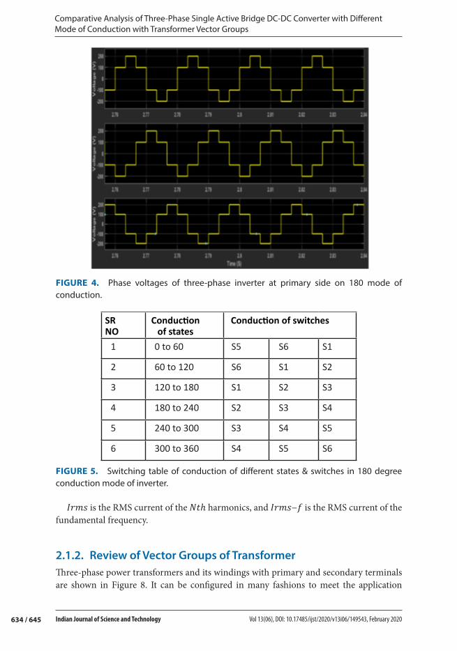
FIGURE 4. Phase voltages of three-phase inverter at primary side on 180 mode of conduction.
SR NO
Conduction of states
Conduction of switches
1 0 to 60 S5 S6 S1
2 60 to 120 S6 S1 S2
3 120 to 180 S1 S2 S3
4 180 to 240 S2 S3 S4
5 240 to 300 S3 S4 S5
6 300 to 360 S4 S5 S6
FIGURE 5. Switching table of conduction of different states & switches in 180 degree conduction mode of inverter.

635 / 645
Mohsin Raza Mahesar, Mukhtiar Ahmed Mahar, Abdul Sattar Larik and Muzamil Hussain Solangi
Indian Journal of Science and Technology Vol 13(06), DOI: 10.17485/ijst/2020/v13i06/149543, February 2020
requirements. International Electro technical Commission (IEC), uses standard coding for each winding connection of a three-phase transformer called the transformer vector group, usually attached to the transformer body [12]. A phase shift can exist between two sidelines voltages vary in the step of 30° for various connections. The phase shift between
SR
No
Conduction of
states
Conduction of switches
1 0 to60 S5 S6 S1
2 60 to120 S6 S1 S2
3 120 to 180 S1 S2 S3
4 180 to240 S2 S3 S4
5 240 to300 S3 S4 S5
6 300 to 360 S4 S5 S6
FIGURE 7. Switching table of conduction of different states & switches in 150 degree conduction mode of inverter.
FIGURE 6. Phase voltages of three-phase inverter at primary side on 150 mode of conduction.

Comparative Analysis of Three-Phase Single Active Bridge DC-DC Converter with Different Mode of Conduction with Transformer Vector Groups
636 / 645 Indian Journal of Science and Technology Vol 13(06), DOI: 10.17485/ijst/2020/v13i06/149543, February 2020
the HT and LT line voltage is very similar to the clock system [15]. The minute needle is for (H.T) voltage and it as shown in Figure 9. Clock, and hour needle for (L.T) line voltage which moves clockwise (HT voltage leading) or anti-clockwise (LT voltage leading) concerning minute needle, that can be easily understood from Figure 9 [16]. For example, the vector group Yd11 shows the HT side is star connected, LT side is delta connected and 11 means phase shifts between the two-line voltages is 30°, LT line voltage leading HT line voltage.
2.1.3. Importance of Transformer Vectors GroupsThe electrical distribution network’s performance is very well concerned with the winding configuration of transformers. These have the harmonics canceling capability at PCC [17]. Either it is stability problem, parallel operation of these transformers or it is the control of real power flow in transmission network selection of a proper vector group at a strategic point for a specific mean has the significance responsibilities. Applications of various vector groups of transformers are depicted in Figure 10 which shows a single line diagram of the power system network. The generation side uses Yd or Dy standard vector group.
FIGURE 8. Three-phase transformer. FIGURE 9. Concept of phase shift is always stationary at 12 O’.
FIGURE 10. Transformer connections from generation to distribution levels.

637 / 645
Mohsin Raza Mahesar, Mukhtiar Ahmed Mahar, Abdul Sattar Larik and Muzamil Hussain Solangi
Indian Journal of Science and Technology Vol 13(06), DOI: 10.17485/ijst/2020/v13i06/149543, February 2020
Since transmission system voltage is very high and it is encountered to large unbalance loading, Dd0 or Dd6 usually selected to suppress unbalance loading ripples. Yd1 or Yd11 are suitable to step up voltage level and Dy1 or Dy11 are designed to step down voltage level.
3. Simulation ModelTo investigate the performance of the SAB3 with various transformer vector groups, comprehensive simulations are performed on MATLAB/SIMULINK environment. The simulation model is shown in Figure 11.
3.1. AssumptionsSAB3 DC-DC converter is supplied 600 DC voltage, and load R 100Ω, L 400 mH. The simulation of the SAB3 is confined in range of the core saturation limit.
4. Results and Discussion The performance of SAB3 is analyzed utilizing FFT algorithm of MATLAB. Simulations are carried on both resistive and inductive loads. In order to compare the performance of SAB3 when connected through various vector group of transformers, first it is simulated
FIGURE 11. Simulation model of three-phase single active bridge DC-DC converter (SAB3).
Comparative Analysis of Three-Phase Single Active Bridge DC-DC Converter with Different Mode of Conduction with Transformer Vector Groups
638 / 645 Indian Journal of Science and Technology Vol 13(06), DOI: 10.17485/ijst/2020/v13i06/149543, February 2020
and analyzed alone to confirm the theoretical calculated THD of three-phase rectifier without connecting any transformer vector group.
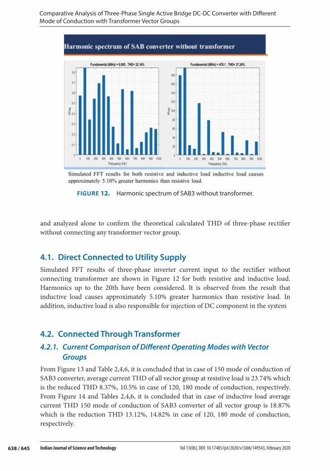
4.1. Direct Connected to Utility SupplySimulated FFT results of three-phase inverter current input to the rectifier without connecting transformer are shown in Figure 12 for both resistive and inductive load. Harmonics up to the 20th have been considered. It is observed from the result that inductive load causes approximately 5.10% greater harmonics than resistive load. In addition, inductive load is also responsible for injection of DC component in the system
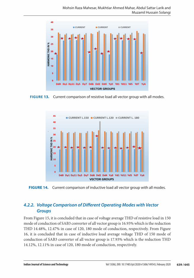
4.2. Connected Through Transformer4.2.1. Current Comparison of Different Operating Modes with Vector
GroupsFrom Figure 13 and Table 2,4,6, it is concluded that in case of 150 mode of conduction of SAB3 converter, average current THD of all vector group at resistive load is 23.74% which is the reduced THD 8.37%, 10.5% in case of 120, 180 mode of conduction, respectively. From Figure 14 and Tables 2,4,6, it is concluded that in case of inductive load average current THD 150 mode of conduction of SAB3 converter of all vector group is 18.87% which is the reduction THD 13.12%, 14.82% in case of 120, 180 mode of conduction, respectively.
FIGURE 12. Harmonic spectrum of SAB3 without transformer.
639 / 645
Mohsin Raza Mahesar, Mukhtiar Ahmed Mahar, Abdul Sattar Larik and Muzamil Hussain Solangi
Indian Journal of Science and Technology Vol 13(06), DOI: 10.17485/ijst/2020/v13i06/149543, February 2020
4.2.2. Voltage Comparison of Different Operating Modes with Vector Groups
From Figure 15, it is concluded that in case of voltage average THD of resistive load in 150 mode of conduction of SAB3 converter of all vector group is 16.93% which is the reduction THD 14.48%, 12.47% in case of 120, 180 mode of conduction, respectively. From Figure 16, it is concluded that in case of inductive load average voltage THD of 150 mode of conduction of SAB3 converter of all vector group is 17.93% which is the reduction THD 14.12%, 12.11% in case of 120, 180 mode of conduction, respectively.
0
5
10
15
20
25
30
35
40
Dd0 Dy1 Dy11 Dy5 Dy7 Dd6 Dd2 Dd4 Yy0 Yd1 Yd11 Yd5 Yd7 Yy6
HAR
MO
NIC
TH
D IN
%
VECTOR GROUPS
CURRENT CURRENT CURRENT
FIGURE 13. Current comparison of resistive load all vector group with all modes.
.
0
5
10
15
20
25
30
35
40
45
Dd0 Dy1 Dy11 Dy5 Dy7 Dd6 Dd2 Dd4 Yy0 Yd1 Yd11 Yd5 Yd7 Yy6
HARM
ON
IC T
HD IN
%
VECTOR GROUPS
CURRENT L.150 CURRENT L.120 CURRENT L. 180
FIGURE 14. Current comparison of inductive load all vector group with all modes.

Comparative Analysis of Three-Phase Single Active Bridge DC-DC Converter with Different Mode of Conduction with Transformer Vector Groups
640 / 645 Indian Journal of Science and Technology Vol 13(06), DOI: 10.17485/ijst/2020/v13i06/149543, February 2020
0
5
10
15
20
25
30
35
40
Yy0 Yd1 Yd11 Yd5 Yd7 Yy6 Dd0 Dy1 Dy11 Dy5 Dy7 Dd6 Dd2 Dd4
HARM
ON
IC T
HD IN
%
VECTOR GROUPS
Voltage R.180 Voltage R.120 Voltage R.150
FIGURE 15. Voltage comparison of resistive load all vector group with all modes.
.
0
5
10
15
20
25
30
35
Yy0 Yd1 Yd11 Yd5 Yd7 Yy6 Dd0 Dy1 Dy11 Dy5 Dy7 Dd6 Dd2 Dd4
HA
RM
ON
IC T
HD
IN %
VECTOR GROUPS
Voltage R-L.180 Voltage R-L.120 Voltage R-L.150
FIGURE 16. Voltage comparison of inductive load all vector group with all modes.
Dd0 Dy1 Dy11 Dy5 Dy7 Dd6 Dd2 Dd4 Yy0 Yd1 Yd11 Yd5 Yd7 Yy60
5
10
15
20
25
30
VECTOR GROUPS
TH
D I
N P
ER
CE
NTA
GE
IN
%
vectR group R. LOAD vectR group L. LOAD
FIGURE 17. Current comparison of resistive and inductive load of 150 mode of conduction.

641 / 645
Mohsin Raza Mahesar, Mukhtiar Ahmed Mahar, Abdul Sattar Larik and Muzamil Hussain Solangi
Indian Journal of Science and Technology Vol 13(06), DOI: 10.17485/ijst/2020/v13i06/149543, February 2020
FIGURE 18. Voltage comparison of resistive and inductive load of 150 mode of conduction.
TABLE 2. Current THD results of SAB3 with 150 mode with transformer vector group
Sr. no Vector group Phase shift Current THD%
R R-L
1 Yy0 0 17.93 118.252 Yd1 −30 27.70 18.293 Yd11 +30 27.60 18.014 Yd5 −150 27.70 18.145 Yd7 +150 27.56 18.396 Yy6 +180 18.13 17.917 Dd0 0 17.88 18.04.8 Dy1 −30 27.41 18.609 Dy11 +30 27.80 18.4210 Dy5 −150 27.73 18.2911 Dy7 +150 27.87 18.2312 Dd6 +180 18.21 17.8713 Dd2 −60 20.68 27.8114 Dd4 −120 18.19 17.95
TABLE 3. Voltage THD results of SAB3 with 150 mode with transformer vector groups
Sr. no Vector groups Phase shift Voltage THD%
R R-L
1 Yy0 0 16.86.86 16.832 Yd1 −30 16.91 16.853 Yd11 +30 16.85 16.844 Yd5 −150 16.93 16.815 Yd7 +150 16.88 16.926 Yy6 +180 16.82 16.87

Comparative Analysis of Three-Phase Single Active Bridge DC-DC Converter with Different Mode of Conduction with Transformer Vector Groups
642 / 645 Indian Journal of Science and Technology Vol 13(06), DOI: 10.17485/ijst/2020/v13i06/149543, February 2020
7 Dd0 0 16.8.8 16.96.98 Dy1 −30 16.84 16.829 Dy11 +30 16.86 16.8410 Dy5 −150 16.80 16.8711 Dy7 +150 16.88 16.8512 Dd6 +180 16.87 16.9113 Dd2 −60 17.87 17.8114 Dd4 −120 16.81 16.87
TABLE 4. Current THD results of SAB3 with 120 mode with transformer vector groups
Sr. no Vector groups Phase shift Current THD%
R R-L
1 Yy0 0 32.39 32.592 Yd1 −30 31.42 31.363 Yd11 +30 31.43 31.444 Yd5 −150 31.47 31.055 Yd7 +150 33.96 31.446 Yy6 +180 32.27 32.597 Dd0 0 32.93 32.928 Dy1 −30 31.51 31.319 Dy11 +30 31.54 31.3910 Dy5 −150 31.48 31.3911 Dy7 +150 31.44 31.3412 Dd6 +180 32.30 32.6713 Dd2 −60 33.36 33.4514 Dd4 −120 32.20 32.71
TABLE 5. Voltage THD results of SAB3 with 120 mode with transformer vector groups
Sr no Vector group Phase shift Voltage THD%
R R-L
1 Yy0 0 30.93 31.132 Yd1 −30 31.08 31.083 Yd11 +30 31.07 31.084 Yd5 −150 31.08 31.265 Yd7 +150 33.68 31.086 Yy6 +180 31.14 31.137 Dd0 0 33.13 33.148 Dy1 −30 31.01 31.099 Dy11 +30 31.00 31.0810 Dy5 −150 31.01 31.0911 Dy7 +150 31.22 31.0812 Dd6 +180 31.07 31.0713 Dd2 −60 31.08 31.2214 Dd4 −120 31.07 30.95

643 / 645
Mohsin Raza Mahesar, Mukhtiar Ahmed Mahar, Abdul Sattar Larik and Muzamil Hussain Solangi
Indian Journal of Science and Technology Vol 13(06), DOI: 10.17485/ijst/2020/v13i06/149543, February 2020
From the results, it is concluded that 150 mode of conduction of SAB3 converter gives lesser value of THD in terms of current and voltage for both resistive and inductive load as shown in Tables 3,5,7.
4.2.3. Voltage and Current Comparison of 150 Mode of Operation with Vector Groups
In Figures 17 and 18, it is concluded that in case of 150 mode of operation, at resistive load vector group Dd0 and Yy0 have best harmonics compressing capability of 14.26% and
TABLE 6. Current THD results of SAB3 with 180 mode with transformer vector groups
Sr no Vector groups Phase shift Current THD%
R R-L
1 Yy0 0 31.70 31.692 Yd1 −30 32.62 32.603 Yd11 +30 32.23 32.204 Yd5 −150 32.78 32.605 Yd7 +150 32.73 32.206 Yy6 +180 31.77 31.627 Dd0 0 31.97 31.898 Dy1 −30 32.28 32.059 Dy11 +30 31.99 32.2010 Dy5 −150 31.99 31.3211 Dy7 +150 32.52 32.7512 Dd6 +180 31.91 32.0413 Dd2 −60 34.19 40.7414 Dd4 −120 31.78 31.88
TABLE 7. Voltage THD results of SAB3 with 180 mode with transformer vector groups
Sr no Vector groups Phase shift Voltage THD%
R R-L
1 Yy0 0 31.15 31.512 Yd1 −30 31.00 31.013 Yd11 +30 31..00 31.004 Yd5 −150 31.22 31.005 Yd7 +150 31.23 31.006 Yy6 +180 31.08 31.087 Dd0 0 31.155 31.308 Dy1 −30 31.34 31.239 Dy11 +30 31.25 31.0010 Dy5 −150 31.25 30.7811 Dy7 +150 31.08 31.2212 Dd6 +180 31.28 30.8013 Dd2 −60 31.34 31.0814 Dd4 −120 31.22 31.01

Comparative Analysis of Three-Phase Single Active Bridge DC-DC Converter with Different Mode of Conduction with Transformer Vector Groups
644 / 645 Indian Journal of Science and Technology Vol 13(06), DOI: 10.17485/ijst/2020/v13i06/149543, February 2020
14.2%, respectively. In case of inductive load preference must be given to Dy6, Dd4, and Yd6 which resourced current THD 19.37%, 19.29%, and 19.33%, respectively Table 2-3.
5. ConclusionHarmonics produced due to three-phase single active bridge SAB3 have their own natural spectrum, consequently mitigation of harmonics in the system from SAB3 and selecting a suitable and reliable method will be cost effective. This study shows the comparative analysis of SAB3 with various vector groups of transformers with different operating modes of three-phase inverter in terms of total harmonics distortion of voltage and current. From the above results, it is concluded that in 150 mode of conduction of SAB3 converter gives lesser value of THD in terms of current and voltage for both resistive and inductive load.
A compromise is need to be made between current THD and voltage THD that is to be minimized, since from the results it is clear that for resistive load vector groups Dd0 or Yy0 efficiently reduced harmonics than other vector groups but at the same time Dd2 has raised voltage THD beyond the standard limit. Thus it is recommended that when such a load which is very sensitive to voltage change connected at PCC, then vector group Dd2 should not be used between three-phase inverter and rectifier.
AcknowledgementThe authors are thankful to Mehran University of Engineering and Technology Jamshoro, (MUET) Pakistan, for providing all needed services for the achievement of this research work.
References 1. Sang Y, Junyent-Ferré A, Green TC, editors. Transformer design in a medium voltage DC/DC
converter for a DC collection network. In: 2017 19th European conference on power electronics and applications. 2017. https://doi.org/10.23919/EPE17ECCEEurope.2017.8099269
2. Jacobs J, Thommes M, De Doncker R, editors. A transformer comparison for three-phase single active bridges. In: 2005 European conference on power electronics and applications. 2005. https://doi.org/10.1109/EPE.2005.219599
3. Sommer C, Mertens A, Larrazabal I, Kortazar I, editors. Analytical investigation of the three-phase single active bridge for offshore applications. In: 2016 18th European conference on power electronics and applications (EPE’16 ECCE Europe). 2016. https://doi.org/10.1109/EPE.2016.7695590
4. Park K, Chen Z, editors. Analysis and design of a parallel-connected single active bridge DC-DC converter for high-power wind farm applications. In: 2013 15th European conference on power electronics and applications (EPE). 2013. https://doi.org/10.1109/EPE.2013.6631854
5. Boudrias J, editor. Harmonic mitigation, power factor correction and energy saving with proper transformer and phase shifting techniques. In: Canadian conference on electrical and computer engineering. 2004. https://doi.org/10.1109/CCECE.2004.1344974

645 / 645
Mohsin Raza Mahesar, Mukhtiar Ahmed Mahar, Abdul Sattar Larik and Muzamil Hussain Solangi
Indian Journal of Science and Technology Vol 13(06), DOI: 10.17485/ijst/2020/v13i06/149543, February 2020
6. Zahira R, Fathima AP. A technical survey on control strategies of active filter for harmonic suppression. Procedia Engineering. 2012; 30, 686–693. https://doi.org/10.1016/j.proeng.2012.01.915
7. Ting Y, De Haan S, Ferreira B. Modular single-active bridge DC-DC converters: efficiency optimization over a wide load range. IEEE Industry Applications Magazine. 2016; 22(5), 43–52. https://doi.org/10.1109/MIAS.2015.2459086
8. Patel DK, Chauhan J, Patel AR, Mishra N, editors. A user friendly simulation for transformer vector group. In: 2012 international conference on communication systems and network technologies. 2012.https://doi.org/10.1109/csnt.2012.178
9. Meng F, Gao L, Yang S, Yang W. Effect of phase-shift angle on a delta-connected autotransformer applied to a 12-pulse rectifier. IEEE Transactions on Industrial Electronics. 2015; 62(8), 4678–4690. https://doi.org/10.1109/TIE.2015.2405058
10. Mahar MA, Uqaili MA, Larik AS. Harmonic analysis of ac-dc topologies and their impacts on power systems. Mehran University Research Journal of Engineering & Technology. 2011; 30(1), 173–178.
11. Bhutia B, Ali S, Tiadi N. Design of three phase PWM voltage source inverter for photovoltaic application. International Journal of Innovative Research in Electrical, Electronics, Instrumentation and Control Engineering. 2014; 2(4), 1364–1367. https://doi.org/10.1109/ICCCE.2016.43
12. Chokkalingham B, Padmanaban S, Blaabjerg F. Investigation and comparative analysis of advanced PWM techniques for three-phase three-level NPC-MLI drives. Electric Power Components and Systems. 2018; 46(3), 258–269. https://doi.org/10.1080/15325008.2018.1445142
13. Mahar M, Abro M, Larik A. Artificial neural network control of sab dc/dc converter. Mehran University Research Journal of Engineering and Technology. 2009; 28(4), 591–592. https://inis.iaea.org/search/search.aspx?orig_q=RN:41000959
14. Liu H, Dahidah M, Naayagi RT, Armstrong M, Yu J. Unidirectional DC/DC modular multilevel converter for offshore wind farm with the control strategy based on stationary frame. The Journal of Engineering. 2019; 2019(17), 4309–4314. https://doi.org/10.1049/joe.2018.8003
15. Lawhead L, Hamilton R, Horak J, editors. Three phase transformer winding configurations and differential relay compensation. In: 60th annual Georgia tech protective relay conference. 2006. https://doi.org/10.1109/PCICON.2007.4365778
16. Katuara S, Gemmani S. Simulink analysis of vector groups of transformers installed at 132kV grid station Qasimabad Hyderabas and their effects on system operation. International Journal of Science and Research. 2016, 1697–1701. http://www.academia.edu/download/43630603/NOV152593.pdf
17. Mahar MA. Analysis and design of neural network controller of single active bridge converter [Doctoral dissertation]. Mehran University of Engineering & Technology: Jamshoro. http://prr.hec.gov.pk/jspui/handle/123456789/1685