issue 1 digital uhp metal-sealed mass flow controllers ... · digital uhp metal-sealed mass flow...
TRANSCRIPT

5Installation and Operation Manual
X-6950-6960March, 2000
Issue 1
Digital UHP Metal-SealedMass Flow ControllersModel 6950andMass Flow MetersModel 6960
DeviceNet Downport
Analog I/O, VCRs
IMPORTANT NOTICEThis IOM is also applicable to Metal
Sealed Models 6850 & 6860Non-UHP MFC/MFM's

Essential InstructionsRead this page before proceeding!
Brooks Instrument designs, manufactures and tests its products to meet many national andinternational standards. Because these instruments are sophisticated technical products, you mustproperly install, use and maintain them to ensure they continue to operate within their normalspecifications. The following instructions must be adhered to and integrated into your safety programwhen installing, using and maintaining Brooks Products.
• Read all instructions prior to installing, operating and servicing the product. If this instruction manualis not the correct manual, telephone 888-554-FLOW or 215-362-3700 and the requested manualwill be provided. Save this instruction manual for future reference.
• If you do not understand any of the instructions, contact your Brooks Instrument representative forclarification.
• Follow all warnings, cautions and instructions marked on and supplied with the product.
• Inform and educate your personnel in the proper installation, operation and maintenance of theproduct.
• Install your equipment as specified in the installation instructions of the appropriate instructionmanual and per applicable local and national codes. Connect all products to the proper electricaland pressure sources.
• To ensure proper performance, use qualified personnel to install, operate, update, program andmaintain the product.
• When replacement parts are required, ensure that qualified people use replacement parts specifiedby Brooks Instrument. Unauthorized parts and procedures can affect the product's performanceand place the safe operation of your process at risk. Look-alike substitutions may result in fire,electrical hazards or improper operation.
• Ensure that all equipment doors are closed and protective covers are in place, except whenmaintenance is being performed by qualified persons, to prevent electrical shock and personalinjury.
Handling Procedure:1. Power to unit must be removed.2. Personnel must be grounded, via a wrist strap or other safe, suitable means before any printed circuit card or
other internal device is installed, removed or adjusted.3. Printed circuit cards must be transported in a conductive bag or other conductive container. Boards must not be
removed from protective enclosure until immediately before installation. Removed boards must immediately beplaced in protective container for transport, storage or return to factory.
CommentsThis instrument is not unique in its content of ESD (electrostatic discharge) sensitive components. Most modernelectronic designs contain components that utilize metal oxide technology (CMOS, etc.). Experience has proventhat even small amounts of static electricity can damage or destroy these devices. Damaged components, eventhough they appear to function properly, exhibit early failure or degraded performance.

i
Contents
Contents
Section 1Introduction
ParagraphNumber Page
1-1 Scope ................................................................................ 1-11-2 Purpose ............................................................................. 1-11-3 Description ........................................................................ 1-11-4 Specifications .................................................................... 1-2
Section 2Installation
2-1 General .............................................................................. 2-12-2 Receipt of Equipment ........................................................ 2-12-3 Recommended Storage Practice....................................... 2-22-4 Return Shipment ............................................................... 2-22-5 Removal from Storage....................................................... 2-22-6 Gas Connections ............................................................... 2-32-7 Installation ......................................................................... 2-32-8 In-Line Filter ...................................................................... 2-42-9 Electrical Interface ............................................................. 2-42-10 Operation Check Procedure .............................................. 2-5
Section 3Operation
3-1 Overview ........................................................................... 3-13-2 Theory of Operation .......................................................... 3-13-3 Features ............................................................................ 3-23-4 Adaptive Valve Control ....................................................... 3-43-5 Analog Mode of Operation................................................. 3-4
Section 4Maintenance
4-1 Overview ........................................................................... 4-14-2 Troubleshooting ................................................................. 4-14-3 Gas Conversion Factors .................................................... 4-54-4 Orifice Sizing ..................................................................... 4-64-5 Restrictor Sizing ................................................................ 4-9
Section ACE Certification
CE Certification of Mass Flow Equipment ......................... A-1
CONTENTS

ii
Brooks Instrument Digital UHP Metal Sealed Model 6950 MFC's and Model 6960 MFM's
FiguresFigureNumber Page
1-1 Model 6950 D-Connector Dimensions............................... 1-41-2 Model 6960 D-Connector Dimensions............................... 1-5
2-1 D-Connector Shielded Cable Hookup Diagram -Voltage I/O Version ............................................................ 2-6
2-2 Common Electrical Hookups Current I/O Version .............. 2-6
3-1 Externally Accessible Adjustments .................................... 3-23-2 Flow Sensor Operational Diagram .................................... 3-33-3 Flow Control System Block Diagram ................................. 3-6
4-1 Bench Troubleshooting Circuit ........................................... 4-34-2 Model 6950 Orifice Sizing Nomograph ............................. 4-134-3 Example Nomograph ........................................................ 4-14
TablesTableNumber Page
2-1 Recommended Filter Size ................................................. 2-4
3-1 Typical Resistor Values ...................................................... 3-5
4-1 Bench Troubleshooting ...................................................... 4-34-2 Sensor Troubleshooting ..................................................... 4-44-3 Orifice Capacities .............................................................. 4-54-4 Conversion Factors (Nitrogen Base) ................................ 4-104-5 Model 6950 Standard Restrictors ..................................... 4-15
1-1
Introduction
Introduction
1-1 Scope
Thank you for purchsing a Brooks® Instrument Model 6950 Mass FlowController (MFC) or Model 6960 Mass Flow Meter (MFM). This manual,X-6950-6960 is a complete installation and operation manual for yourinstrument.
1-2 Purpose
The Brooks 6900 Series are mass flow measurement devices designed foraccurately measuring (MFM's) and rapidly controlling (MFC's) flows ofgases. This instruction manual is intended to provide the user with all theinformation necessary to install, operate and maintain the Brooks Model6950 MFC and the Model 6960 MFM. This manual is organized into foursections.
Section 1 INTRODUCTIONSection 2 INSTALLATIONSection 3 OPERATIONSection 4 MAINTENANCE
It is recommended that this manual be read in its entirety before attemptingto operate or repair the Model 6950 or Model 6960.
1-3 Description
The Brooks Model 6960 Mass Flow Meter (MFM) is a high precision gasflow measuring device. The Model 6950 Mass Flow Controller (MFC) is acomplete, closed-loop system for controlling flow. They are designed foruse in advanced, ultra-clean gas handling systems requiring deterministicperformance, superior accuracy, and diagnostic capabilities. Theseinstruments feature ultra-polished internal surfaces and all metal inboardand outboard seals.
Section1

Brooks Instrument Digital UHP Metal Sealed Model 6950 MFC and Model 6960 MFM
1-2
1-4 Specifications
Do not operate this instrument in excess of the specifications listed below. Failure to heed this warning can result in serious personal injury and/or damage to the equipment.
WARNING
Physical:
Materials of Construction316L Vacuum Arc Remelt (VAR), 316L, and high alloy ferritic stainlesssteel.
External/internal sealsNickel
Valve seat (MFC only)316L
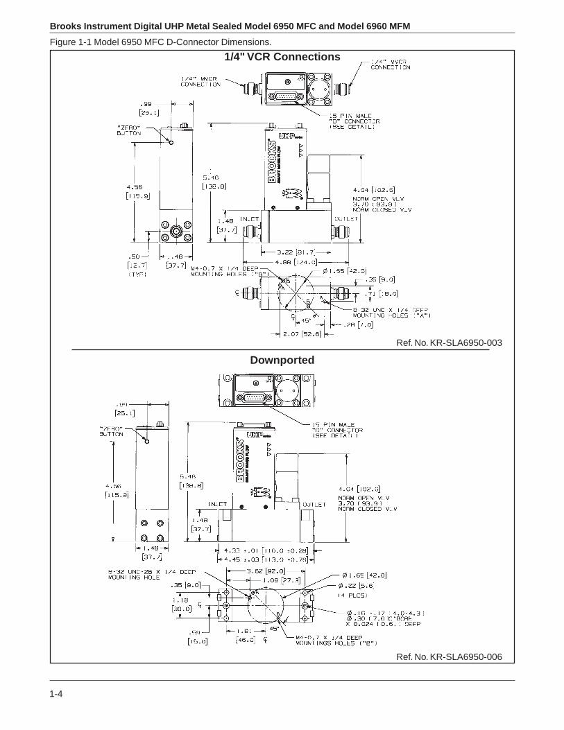
DimensionsRefer to Figure 1-1 for a Model 6950 Mass Flow Controller, Figure 1-2 for aModel 6960 Mass Flow Meter.
Process ConnectionsIntegral 1/4" male VCRTM
C Seal Downport (semi spec. 2787.1 4/99)CS Seal Downport (semi spec. 2787.5 4/99)
Performance Characteristics:
Flow Ranges*Metal Valve Seat: (MFC only)Any full-scale flow rate from 3 sccm to 30,000 sccm Nitrogen equivalentflow at standard temperature and pressure.
*Standard temperature and pressure are in accordance with SEMIStandard E12-96: 0°C and 101.32 kPa (760 torr).
Accuracy±1.0% of rate over range from 20% to 100% FS. ±0.2% of full-scale below20% full-scale.
Repeatability±0.25% of rateSettling TimeLess than one second to within ±2% full-scale of final value for a 0 to100% command step, per SEMI Guideline E17-91.
Control Range (MFC only)Metal Valve Seat:33 to 1

1-3
Introduction
Mounting Attitude Sensitivity0.5% of FS maximum deviation after rezeroing
Leak IntegrityInboard to Outboard: 1x10-11 atm scc/sec Helium max.
Temperature SensitivityZero: Less than 0.075% FS per Deg CSpan: Less than ±1% FS shift over 10-50 Deg C range
Ambient Temperature LimitsOperating: 0°C to 65°C (32°F to 149°F)Non-Operating: -25°C to 100°C (-13°F to 212°F)
ParticulateZero particles per cubic foot greater than 0.1 microns under processconditions. Less than 4 particles per cubic foot greater than 0.02 micronsunder process conditions.
Maximum Operating Pressure Range1500 psig; 150 psig maximum recommended pressure for bestperformance; 5-50 psid pressure drop (minimum pressure drop dependson gas and range - consult factory)
Electrical Characteristics:
Power Supply RequirementsMaximum: +15 Vdc (±5%) at 340 mA
Power Supply SensitivityNone within ±15 Vdc ±5% specified voltage (See Power Requirements)
Setpoint Input (Analog Mode)0-5 Vdc; Input will accept signals up to 6 Vdc and down to -.5 Vdc (120%FS)(Input resistance 15KΩ min.)
Output Signal0-5 Vdc into 2 KΩ minimum.Output will indicate flow signals to 6 Vdc (120%FS).
Electrical Connections15 pin ‘D’ Connector
Brooks Instrument Digital UHP Metal Sealed Model 6950 MFC and Model 6960 MFM
1-4
Figure 1-1 Model 6950 MFC D-Connector Dimensions.
1/4" VCR Connections
Downported
Ref. No. KR-SLA6950-003
Ref. No. KR-SLA6950-006

1-5
Introduction
Figure 1-2 Model 6960 MFM D-Connector Dimensions.
1/4" VCR Connections
Downported
Ref. No. KR-SLA6950-006
Ref. No. KR-SLA6950-003

Brooks Instrument Digital UHP Metal Sealed Model 6950 MFC and Model 6960 MFM
1-6
Figure 1-1 Model 6950 MFC DeviceNet Dimensions.
1/4" VCR Connections
Downported
Ref. No. KR-SLA6950-002
Ref. No. KR-SLA6950-005

2-1
Installation
Installation
2-1 General
This section provides installation instructions for the Brooks Model 6950MFC and Model 6960 MFM. Figure 1-1 (‘D’ Connector) show the Model6950 dimensions, gas connections and electrical connection locations foran MFC, refer to Figure 1-2 (‘D’ Connector) for the Model 6960 MFM.
2-2 Receipt of Equipment
When the equipment is received, the outside packing case should bechecked for damage incurred during shipment. If the packing case isdamaged, the local carrier should immediately be notified regarding hisliability. A report should be submitted to the Product Service Department,Brooks Instrument, 407 West Vine Street, Hatfield, Pennsylvania 19440.
Remove the envelope containing the packing list. Outside of your cleanarea, carefully remove the equipment from the packing case. Make surespare parts are not discarded with the packing material. Inspect fordamaged or missing parts.
This device has been assembled, calibrated and double-vacuum bagged ina Class 100 clean room. In your semi-clean area,remove the outer bagonly. Pass your Model 6950 Ultra-Clean Metal Seal Mass Flow Controllerinto your clean area. Remove the second clean room compatible bag onlywhen the equipment is ready to be tested and/or installed in your cleansystem.
Section2

Brooks Instrument Digital UHP Metal Sealed Model 6950 MFC and Model 6960 MFM
2-2
2-3 Recommended Storage Practice
If intermediate or long-term storage is required for equipment, as suppliedby Brooks Instrument, it is recommended that said equipment be stored inaccordance with the following:
a. In the original vacuum bag and shipping container.b. In a sheltered area with the following conditions:
1. Ambient temperature 21°C (70°F) nominal, 32°C (90°F) maximumand 7°C (45°F) minimum.
2. Relative humidity 45% nominal, 60% maximum and 25% minimum.
2-4 Return Shipment
Prior to returning any Brooks equipment to the factory, contact the factoryfor a Return Materials Authorization Number (RMA#). This can be obtainedat Brooks Instrument, Product Service Department, 407 West Vine Street,Hatfield, PA 19440, or call toll free 1-888-554-FLOW (3569).
Also, completion of Form RPR003-1, Brooks Instrument DecontaminationStatement, as well as, a Material Safety Data Sheet (MSDS) for the fluid(s)used in the meter, is required before any Brooks Personnel can beginprocessing the equipment. Copies of the form can be obtained at thelocations listed below.
Brooks Instrument407 W. Vine StreetP.O. Box 903Hatfield, PA 19440 USAToll Free (888) 554-FLOW (3569)Tel (215) 362-3700Fax (215) 362-3745Email [email protected]://www.brooksinstrument.com
Brooks Instrument B.V. Fisher-Rosemount Japan Co.,Groeneveldselaan 6 Ltd. Brooks DivisionP.O. Box 56 1-4-4 Kitasuna Koto-Ku3900 AB Veenendaal, Netherlands Tokyo 136-0073 JapanTel 31-318-549-549 Tel 011 81-3-5633-7100Fax 31-318-549-559 Fax 011 81-3-5633-7101Email [email protected] Email [email protected]
2-5 Removal from Storage
Upon removal from storage, a visual inspection should be conducted toverify the condition of the equipment is “as received.” If the equipment hasbeen in storage in conditions in excess of those recommended(See Section 2-3), the device should be subjected to a pneumatic pressuretest in accordance with applicable vessel codes. To maintain the ultra-cleanintegrity, this service should be performed by the factory or one of theauthorized service centers.

2-3
Installation
2-6 Gas Connections
Standard inlet and outlet connections supplied on the Model 6950 andModel 6960 are 1/4"(M) VCR. Prior to installation ensure all piping is cleanand free from obstructions. Install piping in such a manner that permitseasy access to the instrument if removal becomes necessary.
2-7 Installation
Recommended installation procedures:a. The Model 6950 MFC and Model 6960 MFM should be located in a
clean, dry atmosphere relatively free from shock and vibration.b. Leave sufficient room for access to Self-zero function push-button.c. Install in such a manner that permits easy removal if the instrument
requires servicing.
d. The Model 6950 MFC and Model 6960 MFM can be installed in anyposition. However, mounting in orientations other than the originalfactory calibration (see calibration data sheet supplied with the instru-ment) can result in a ±0.5% maximum full scale shift after re-zeroing.
Use caution when installing surface mount (downported) controllers. Most metal seals can not be reused after compression. Follow the seal manufacturers’ recommendations for installation. Tighten the mounting screws in 10 in-lb. increments such that the seal undergoes uniform compression. Final torque values depend on the screw and hardware material and lubrication.
CAUTION
e. When installing a mass flow controller or meter with full scale flow ratesof 10 slpm or greater, be aware that sharp, abrupt angles in the systempiping directly upstream of the controller may cause a small shift inaccuracy. If possible, have at least ten pipe diameters of straight tubingupstream of the mass flow controller or meter.

Brooks Instrument Digital UHP Metal Sealed Model 6950 MFC and Model 6960 MFM
2-4
2-8 In-Line Filter
It is recommended that an in-line filter be installed upstream from the massflow controller or meter to prevent the possibility of any foreign materialentering the flow sensor or control valve (MFC). The filtering elementshould be replaced periodically or ultrasonically cleaned.
Table 2-1. Recommended Filter Size.Maximum Flow Rate Recommended Filter
100 sccm 1 micron500 sccm 2 micron
1 to 5 slpm 7 micron10 to 30 slpm 15 micron
2-9 Electrical Interface
The Model 6950 MFC and Model 6960 MFM are controlled using analog 0-5 Vdc signals. The minimum set of connections which must be made to theModel 6950 MFC and Model 6960 MFM include +15 Vdc, supply common,and a setpoint signal. The setpoint signal is supplied as a 0 to 5 Vdc analogsignal. All signals are supplied via the 15-pin ‘D’ connector.
The Model 6950 MFC and 6960 MFM electrical interface is designed tofacilitate low-loss, quiet signal connections. Separate returns (commons)are supplied for the analog setpoint, analog flow signal, and the powersupply. These commons are electrically connected on the Model 6950MFC and Model 6960 MFM PC board.
Volta ge I/O Version• Chassis Ground• Signal Common• Signal Output• +15 Vdc Supply• -15 Vdc Supply (not used by 6950 MFC)• Command Input• Command Common• Supply Common• Valve Return (not used by 6950 MFC)
2-5
Installation
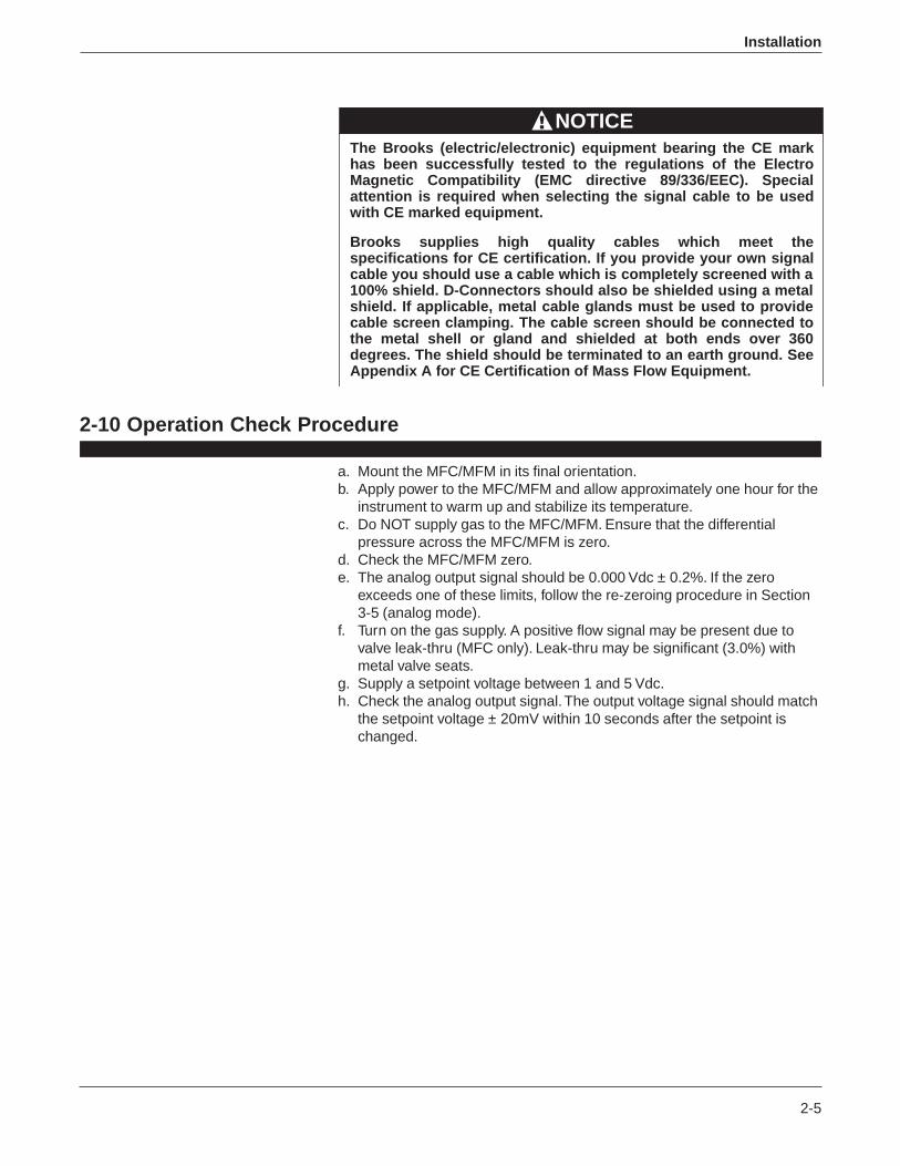
The Brooks (electric/electronic) equipment bearing the CE mark has been successfully tested to the regulations of the Electro Magnetic Compatibility (EMC directive 89/336/EEC). Special attention is required when selecting the signal cable to be used with CE marked equipment.
Brooks supplies high quality cables which meet the specifications for CE certification. If you provide your own signal cable you should use a cable which is completely screened with a 100% shield. D-Connectors should also be shielded using a metal shield. If applicable, metal cable glands must be used to provide cable screen clamping. The cable screen should be connected to the metal shell or gland and shielded at both ends over 360 degrees. The shield should be terminated to an earth ground. See Appendix A for CE Certification of Mass Flow Equipment.
NOTICE
2-10 Operation Check Procedure
a. Mount the MFC/MFM in its final orientation.b. Apply power to the MFC/MFM and allow approximately one hour for the
instrument to warm up and stabilize its temperature.c. Do NOT supply gas to the MFC/MFM. Ensure that the differential
pressure across the MFC/MFM is zero.d. Check the MFC/MFM zero.e. The analog output signal should be 0.000 Vdc ± 0.2%. If the zero
exceeds one of these limits, follow the re-zeroing procedure in Section3-5 (analog mode).
f. Turn on the gas supply. A positive flow signal may be present due tovalve leak-thru (MFC only). Leak-thru may be significant (3.0%) withmetal valve seats.
g. Supply a setpoint voltage between 1 and 5 Vdc.h. Check the analog output signal. The output voltage signal should match
the setpoint voltage ± 20mV within 10 seconds after the setpoint ischanged.

Brooks Instrument Digital UHP Metal Sealed Model 6950 MFC and Model 6960 MFM
2-6
Figure 2-2. Common Electrical Hookups Current I/O Version.
Figure 2-1 D-Connector ShieldedCable Hookup Diagram - VoltageI/O Versions.
Analog I/O Pin Connections:
Signal: 15-pin D-conn 9-pin D-conn
Setpoint/Command Common 1 8
Flow/Signal Out 2 2
+15v 5 3
-15v (unused) 6 9
Setpoint/Command In 8 6
Power Supply Common 9 4
SIgnal Common, Output Return 10 7
+5v reference 11
Valve Override 12 1
Calibration Select Pin 13
Chassis Ground 14
Remote Transducer In 15
1
159
8
Note:* indicates MFC's only
No Connections 3,4,7 5
3-1
Operation
Operation
3-1 Overview
This section contains the following information:• Features and Jumper Configurations• Theory of Operation• Adjustment Potentiometers• Calibration and Response Adjustments
3-2 Theory of Operation for Flow Measurement
The thermal mass flow measurement system consists of two components:the restrictor and the flow sensor. Figure 3-2 contains a diagram of the flowstream of the MFC/MFM with an enlarged view of the flow sensor. Gasflow entering the MFC/MFM is separated into two paths; one straightthrough the restrictor and the other through the flow sensor. This isrepresented in Figure 3-2 where the total flow A+B enters the MFC/MFMand is separated into streams A and B. The streams are joined again at thefar side of the restrictor.
The separation of the flow streams is caused by the restrictor. Therestrictor creates a resistance to flow which results in a difference of gaspressure across the restrictor. This pressure differential forces gas to flowin the sensor.The pressure difference caused by the restrictor varies linearly with totalflow rate. The sensor has the same linear pressure difference versus flowrelationship. The ratio of the flow through the restrictor to the sensor flowremains constant over the range of the MFC/MFM (A/B = constant). Thefull scale flow rate of the MFC/MFM is established by selecting a restrictorwith the correct pressure differential for the desired flow.
The flow sensor is a very narrow, thin-walled stainless steel tube. Onto thistube are built upstream and downstream temperature sensing elements oneither side of a heating element. Constant power is applied to the heaterelement, which is located at the midpoint of the sensor tube. During no-flow conditions, the amount of heat reaching each temperature sensor isequal, so temperatures T1 and T2 (Fig. 3-2) are equal. Gas flowing throughthe tube carries heat away from the upstream temperature sensor andtoward the downstream sensor. The temperature difference, T2 - T1, isdirectly proportional to the gas mass flow. The equation is:
DT = A x P x Cp x m
Where,DT = Temperature difference T2 - T1 (°K)A = Constant of proportionality (S2-°K2/kJ2)P = Heater PowerCp = specific heat of the gas at constant pressure (kJ/kg - °K)
Section3

Brooks Instrument Digital UHP Metal Sealed Model 6950 MFC and Model 6960 MFM
3-2
m = Mass Flow (kg/s)A bridge circuit and a differential amplifier interpret the temperaturedifference and generate an electrical signal directly proportional to the gasmass flow rate.
3-3 Features
Note: All Model 6950 mass flow controllers and Model 6960 mass flowmeters are configured at the factory according to customer order and donot require adjustment. Not all features are available on all instruments.
The Model 6950 is a full-featured digital MFC. The Model 6950 performsmuch like a traditional analog MFC, but with improved accuracy, stepresponse and valve control. The analog interface matches that of Brooks'popular analog MFCs so the Model 6950 can be retrofitted into tools usinganalog MFCs. Other versions of the Model 6950 can provide a varietyof digital protocols, for example DeviceNet.
The Model 6950 is capable of storing up to 10 different sets of gascalibration data. Each set includes a calibration curve, PID controllersettings, valve performance data, and information about the calibrationconditions. The Model 6950 can contain calibrations for different gases orfor the same gas at multiple conditions (pressures, full-scale flow rates).Section 3-5 Analog Mode of Operation describes more information aboutthe data contained in the calibration table and how to access the data.
Calibrations will appear in the calibration table in the same order as theyappeared on the Model 6950 customer order, unless otherwise specified.The first listed gas will appear as calibration #1 the second as calibration#2 and so on. Note that unless specified otherwise on the customer orderModel 6950’s containing a single calibration will have that calibrationstored in calibration #1.
Figure 3-1.Externally Accessible Adjustment.

3-3
Operation
Figure 3-2. Flow Sensor Operational Diagram (VCRTM End Connections Shown)
TruCal Calibration
The 6950/6960 Series also supports the TruCal calibration method. TruCalis an optional level of calibration accuracy available for some specificgases.Traditionally, there has been accuracy problems with thermal flow metersused with gases other than the gas used during calibration. While linearcorrection factors have been calculated for most gases and combinationsbased on thermodynamic properties, these factors are sometimesinadequate. The result is poor accuracy performance for the user.This accuracy problem has existed because many of the problem gasesare dangerous to handle. Brooks developed a patented process thataddresses the accuracy problem and can be implemented safely inproduction. The TruCal process begins with the collection of data for aspecific gas. A MFC is calibrated over its full range using nitrogen and thenevaluated with a specific gas. The evaluation yields a collection of flow rateoutput versus measured flow at multiple setpoints over the range of theMFC.The flow rate data is collected and used to create a new calibrationpolynomial. The new polynomial maps an instrument calibrated (linearized)for nitrogen to a calibration for the specific gas. The new polynomials areused to create accurate instruments while only using nitrogen to performthe calibration. Therefore, it only requires one additional step to perform aTruCal calibration for a customer.A different TruCal polynomial is created for each gas and mixture type,restrictor size, inlet pressure and temperature.
Brooks Instrument Digital UHP Metal Sealed Model 6950 MFC and Model 6960 MFM
3-4
The following paragraphs describe the basic features of the Model 6950.
3-4 Adaptive Valve Control (MFC only)
The Model 6950 offers a feature, called adaptive valve control, whichallows the instrument to learn about the process gas and operatingconditions. If multiple calibrations are being used, the adaptive valvecontrol procedure must be performed separately for each calibration.The adaptive valve control process requires that the process gas besupplied to the Model 6950 at the pressure and temperature which willexist during the process.If the system conditions have changed so substantially that the Model6950 becomes unstable, the adaptive valve control algorithm determinesnew gains which will stabilize the instrument and restore the step responseto the factory performance level.
3-5 Analog Mode of Operation
NOTE: Read Section 3-3, Features, before reading this section.
A. Functional DescriptionThe analog interface is consistent with other Brooks analog MFCs/MFMs.This includes a 0-5 volt setpoint input, 0-5 volt flow signal output, ValveOverride input, and Calibration Select input pin. All analog signals availableare on the 15 pin D-connector with each signal on the same pin as theBrooks Model 5964 MFC (see Fig. 2-5 for connections). Note that oneformerly unused connector pin, pin 13, now allows selection of up to tenseparate calibrations. The contents of the ten calibrations are determinedfrom the customer order, only those calibrations ordered will be available inthe instrument. Unless otherwise specified, a Model 6950 ordered withonly one calibration will have that calibration stored in calibration #1.Before operating the Model 6950, apply power and warm-up theinstrument for approximately one hour. After warm-up, apply gas pressurethen proceed by following the instructions in the following sections.
B. Analog Setpoint (MFC Only)This input allows the user to establish the MFC setpoint. The usable rangeof this input is from 0 to 5.3 Vdc which corresponds to 0 to 104% of theMFC full scale flow rate. The setpoint input is capable of responding toinput changes of 0.5 mV or less. Setpoints below 45 mV will be treated as0 volt setpoints. For setpoints below 0 Vdc the MFC behaves as if a 0 Vdcsetpoint is present. Setpoints above 5.2 Vdc will cause a setpoint of atleast 104% FS.
C. Analog Flow SignalThis output is used to indicate the flow signal. The range of this signal isfrom -0.6 to 5.3 Vdc, with the range of 0 to 6.0 Vdc corresponding to acalibrated flow signal of 0 to 120% of the full scale flow rate. A negativeflow signal indicates reverse flow through the device, but is NOT calibrated.The analog flow signal is capable of resolving signals to 0.5 mV.

3-5
Operation
D. Valve Override (MFC Only)This input allows the valve to be forced to its most closed state or its mostopen state, regardless of setpoint. If this input is not electrically connectedthe MFC will operate according to the current values of the other MFCinputs. If this input is held at 0 Vdc, the valve will be forced to its mostclosed state. If this input is held to +15 Vdc the valve will be forced to itsmost open state.
E. Calibration Select PinOne input, 15 pin ‘D’ Connector pin 13, allows selection of one of tencalibrations stored in the device. This pin is designed to accept pull-downresistors referenced to signal common (pin 10) on the 15 pin ‘D’ connector.Table 3-1 shows typical resistor values required for selecting calibrations 1through 10. Note, these resistor values should be within ± 1% tolerance.The default condition is with no resistor connected which activatesCalibration #1.
When the calibration select pin changes state, the device performs anyrequired processing to change the calibration, then returns to normaloperation. If the device determines that the selected calibration is not valid,(where applicable) the valve is driven to the closed state and the flowsignal is set to zero. Typical time required to change calibrations isapproximately 0.5 seconds.
NOTE: It is recommended to change calibrations during no-flow conditions.
DEFAULT = CAL # 1 (External resistor not installed)CAL # RESISTOR VALUE (ohms) 1 Not Installed 2 665 3 324 4 191 5 124 6 80.6 7 52.3 8 30.9 9 15
10 Shorted
F. Zeroing the MFC (Self-zero)It may be desirable to re-zero the flow sensor if it is operated at itstemperature extremes or if it is positioned in an attitude other than thatspecified on the customer order.Note: Before zeroing the instrument, zero pressure differential MUST beestablished across the device. If there is pressure across the instrumentduring the zero process, any detected flow through the sensor will bemisinterpreted as the zero flow reading. This will result in calibrationinaccuracy during normal operation.
Once zero differential pressure is established and verified, press therecessed, momentary push-button (Self-zero button) located on the side ofthe device (see Fig. 3-1) to start the Self-zero function.
The zero process requires approximately 200mil/sec. During this time, thedevice will set its output signal to 0.0 Vdc.
Table 3-1 Typical Resistor Valuesfor Calibration Select

Brooks Instrument Digital UHP Metal Sealed Model 6950 MFC and Model 6960 MFM
3-6
Figure 3-3 Flow Control System Block Diagram. (MFC only)

4-1
Maintenance
Maintenance
4-1 Overview
No routine maintenance is required on the Model 6950 or Model 6960. Ifan in-line filter is used, the filtering elements should be periodicallyreplaced. This section provides the following information:
• Troubleshooting• Gas Conversion Factors• Orifice Sizing*• Restrictor Sizing
* indicates MFC only
4-2 Troubleshooting
If it becomes necessary to remove the controller from the system after exposure to toxic, pyrophoric, flammable or corrosive gas, purge the controller thoroughly with a dry inert gas such as Nitrogen before disconnecting the gas connections. Failure to correctly purge the controller could result in fire, explosion or death. Corrosion or contamination of the mass flow controller, upon exposure to air, may also occur.
WARNING
This section contains suggestions to help diagnose MFC/MFM relatedproblems in the gas distribution system and answers commonly askedquestions.
a. Problem: Flow/flow signal doesn’t reach setpoint. (MFC Only)Failure of the flow rate or flow signal to achieve the setpoint could becaused by a number of factors:
1. Insufficient pressure drop across the Model 6950 MFC (low or nopressure). If there is not enough pressure differential across the MFC, itis impossible for the MFC’s valve orifice to pass the full scale flow rate.To check for this condition, compare the actual inlet/outlet pressuredrop with that specified on the order. Increase the pressure ifnecessary.
Section4

Brooks Instrument Digital UHP Metal Sealed Model 6950 MFC and Model 6960 MFM
4-2
2. Setpoint is below minimum. MFCs with metal seats may have aleak-through rate of up to 3% of full scale. These instruments are notguaranteed to operate below setpoints of 1.0% FS.
3. Clogged sensor tube. If the MFC sensor tube is clogged, the flow signalwill be very low or zero while the actual flow will be at the valve’smaximum rate.
4. Clogged restrictor. If the MFC restrictor becomes clogged, a much largerportion of the flow stream will pass through the sensor rather than goingstraight through the restrictor. The symptom of this condition is asubstantially reduced actual flow with a flow signal that matches thesetpoint.
5. If the Valve Override pin is active, the valve will be forced open orclosed. Set this pin to its normal level before setting a setpoint.
b. Problem: Flow rate in excess of 100% at zero setpoint.1. Valve Override pin set to open.
c. Problem: Flow/flow signal ‘unstable’.Model 6950 MFC performance is tuned during calibration at theconditions specified on the order. If the conditions in use (inlet andoutlet pressure, temperature, attitude, gas or mixture type) are differentor become different over time, the MFC may not perform as it did whenit left the factory. There are numerous solutions to this situation:
1. Restore the conditions to the values as they appear on the order.
2. ‘Adaptive valve control’ the MFC. The MFC contains a function whichallows it to learn about its environment. Adaptive valve control helps tomatch the valve performance to the gas, pressure, and temperature ofactual use. Carefully read the section on adaptive valve control inSection 3-4.
d. Question: What is the purpose of the recessed push-button on theside of the MFC?Answer: This push-button is used to start a Self-zero function, do NOTpress it unless you are performing this function as described in Section3-5.

4-3
Maintenance
Table 4-1 Bench Troubleshooting for MFC/MFM.Trouble Possible Cause Check/Corrective Action
Output stays at zero level regardless Clogged Sensor tube and restrictor and/or a Clean sensor. Refer to cleaning procedure, Section 4-2D.of command and there is no flow clogged orifice.through the controller.
Closed or clogged flow path up- or downstream or Open valve(s). Clean filter(s). Remove any foreign material from gas delivery system.the controller.
Clogged Control Valve. Check TP3 with the command at 100%. If the voltage is more negative than -11V,disassemble and repair the control valve. Refer to Sections 4-3 and 4-4.
-0 volts applied to the valve override input Check valve override input. Refer to Section 2-6 for terminal assignments.
Defective printed circuit board. Replace printed circuit board. Refer to Section 4-3.
Output signal stays at +6.8 Volts Valve stuck open or leaky. Clean and/or adjust control valve. Refer to cleaning procedure and/or Section 4-2D.(26 mA for Current I/O Vers.) regard-less of command and there is flow +15 Volts applied to the valve override input. Check the valve override terminal. Refer to Section 2-6 for terminal assignments.
through the controller.Defective printed circuit board. Replace printed circuit board. Refer to Section 4-3.
Command input floating. Connect command signal. Refer to Section 2-6 for terminal assignments.
Output signal follows set-point at Leaky control valve Disassemble and repair valve. Refer to Section 4-3.higher commands but will not go tozero.
Output signal follows set-point at Insufficient inlet pressure or pressure drop. Adjust pressures, inspect in-line filters and clear/replace as necessary.lower commands but does not reachfull scale. Partially clogged sensor Check calibration. Refer to Section 3-7.
Partially clogged valve. Disassemble and repair control valve. Refer to Section 4-3.
Controller grossly out of calibration. Partially clogged sensor. Clean sensor. Refer to the cleaning procedure, Section 4-2D.Flow is higher than desired.
Controller grossly out of calibration. Partially clogged restrictor. Replace restrictor. Refer to Section 4-3.Flow is lower than desired.
Controller oscillates. Pressure drop or inlet pressure excessive. Adjust pressures.
Oversized orifice. Check orifice size. Refer to Section 4-6.
Faulty pressure regulator. Check regulator output.
Defective printed circuit board. Replace printed circuit board. Refer to Section 4-3.
Figure 4-1 Bench Troubleshooting Circuit

Brooks Instrument Digital UHP Metal Sealed Model 6950 MFC and Model 6960 MFM
4-4
Remove the sensor connector from the PC Board for this procedure.
OHMMETER CONNECTION RESULT IF ELECTRICALLY FUNCTIONAL
Open circuit on ohmmeter. If either heater (1) orPin 1 or 4 to meter body sensor common (4) are shorted, an ohmmeter
reading will be obtained.
Pin 4 to Pin 2 Nominal 1100 ohms reading, depending on
Pin 4 to Pin 3
Pin 5 to Pin 1 Nominal 1000 ohm reading.
Pin 6 to Pin 7 Nominal ohm reading.
Table 4-2. Sensor Troubleshooting.
temperature and ohmmeter current.
SENSORSCHEMATIC
PINNO. FUNCTION
1 HeaterUpstream
2 TemperatureSensor (Su)Downstream
3 TemperatureSensor (Sd)
4 Sensor Common5 Heater Common

4-5
Maintenance
Table 4-3 Orifice Capacities.Orifice Size (inches) Minimum Flow Rate (sccm)
0°C (21.1°C)0.0013 5.3 (5.7)0.002 12.5 (13.5)0.003 39.2 (42.2)0.004 82.5 (88.9)0.0055 190 (205)0.007 374 (403)0.010 748 (806)0.014 1364 (1469)0.020 2673 (2879)0.032 6490 (6991)0.048 12980 (13980)0.062 22000 (2879)0.078 31900 (34400)0.093 42500 (45800)0.120 69300 (74700)
Inlet Pressure = 10 psigOutlet Pressure = 10 inches of water (0.4 psig) or lessNote: Flow Rate based on Nitrogen
4-3 Gas Conversion Factors
If a mass flow controller is operated on a gas other than the gas it wascalibrated with, a scale shift will occur in the relation between the outputsignal and the mass flow rate. This is due to the difference in heatcapacities between the two gases. This scale shift can be approximated byusing the ratio of the molar specific heat of the two gases or by sensorconversion factor. A list of sensor conversion factors is given in Table 4-5.To change to a new gas, multiply the output reading by the ratio of the gasfactor for the desired gas by the gas factor for the calibration gas used.
Example:The controller is calibrated for Nitrogen.The desired gas is Carbon DioxideThe output reading is 75 sccm when Carbon Dioxide is flowingThen 75 x 0.773 = 57.98 sccm
In order to calculate the conversion factor for a gas mixture, the followingformula should be used:
Where,

Brooks Instrument Digital UHP Metal Sealed Model 6950 MFC and Model 6960 MFM
4-6
P1 = percentage (%) of gas 1 (by volume)
P2 = percentage (%) of gas 2 (by volume)
Pn = percentage (%) of gas n (by volume)
Example: The desired gas is 20% Helium (He) and 80% Chlorine (Cl) byvolume. The desired full scale flow rate of the mixture is 20 slpm. Sensorconversion factor for the mixture is:
Nitrogen equivalent flow = 20/.945 = 21.16 slpm Nitrogen
It is generally accepted that the mass flow rate derived from this equationis only accurate to ±5%. The sensor conversion factors given in Table 4-5are calculated based on a gas temperature of 21°C and a pressure of oneatmosphere. The specific heat of most gases is not strongly pressure, and/or temperature, dependent. However, gas conditions that vary widely fromthese reference conditions may cause an additional error due to thechange in specific heat caused by pressure and/or temperature.
4-4 Orifice Sizing
The Orifice Sizing Nomograph, Figure 4-4, is used to calculate the controlvalve's orifice size when changing any or all of the following factors fromthe original factory calibration:
gasoperating pressure (inlet and outlet)flow range
The flow controller's orifice is factory-sized to a preselected gas, operatingpressure and flow range. Note that the orifice is marked with its size inthousandths of an inch. When changing the aforementioned factors,calculate the new orifice size by following the procedure and exampleoutlined in the following paragraphs.
Example: Determine the orifice size for the following conditions:
Gas: HydrogenFlow Rate: 2,000 sccmOutlet Pressure: 30 psigInlet Pressure: 50 psig
1. Determine Nitrogen equivalent flow rate (refer to Table 4-5).
OR

4-7
Maintenance
Where:Q
NITROGEN= Nitrogen equivalent flow rate (sccm)
QGAS
= Desired flow rate of the gas (sccm)
rNITROGEN
= Density of Nitrogen at 70°F
rGAS
= Density of the gas (taken at customer temperature)
SGGAS
= Specific gravity of the gas (taken at customertemperature)
Refer to Table 4-5 for densities.Example:
Qgas
= 2,000 sccm
= 2,000 x .269
= 538 sccm Nitrogen
In order to calculate the orifice conversion factor when using a gasmixture, the following formula must be used:
Where P1 = percentage by volume of gas 1P2 = percentage by volume of gas 2Pn = percentage by volume of gas n

Brooks Instrument Digital UHP Metal Sealed Model 6950 MFC and Model 6960 MFM
4-8
Example: Find the Nitrogen equivalent for 20 slpm of a 20% Helium and80% Chlorine gas mixture.
QNitrogen
= Qgas
(orifice conversion factor)
= 20 x 1.439
= 28.78 slpm Nitrogen
2. If inlet and outlet pressures are given in gauge pressure (psig) add 14.7to convert to absolute pressure (psia).
Outlet Pressure — 30 psig + 14.7 = 44.7 psiaInlet Pressure — 50 psig + 14.7 = 64.7 psia
3. Determine Critical Pressure DropCritical pressure drop occurs when the outlet pressure (psia) is lessthan half the inlet pressure (psia) or
If these conditions exist, the pressure drop (Dp) should be calculated asfollows:
Dp = Pressure drop (psi)P
in= Inlet pressure (psia)
If these conditions do not exist, pressure drop equals the inlet pressureminus the outlet pressure.
Then Dp = 64.7 - 44.7 = 20 psi
4. Using the nomograph, locate the pressure drop (psi) on the vertical linemarked "Dp" (Point A).
5. Locate the Nitrogen equivalent flow rate (sccm Nitrogen) on the vertical

4-9
Maintenance
line marked "QNitrogen
" (Point B).
6. Draw a line connecting Dp and QNitrogen
and extend it to the baseline.Mark this point (Point C).
7. Locate inlet pressure (psia) on the vertical line marked "Pin" (Point D).
8. Draw a line connecting Pin
(Point D) and baseline (Point C) and thenextend this line to the vertical line marked D
o (orifice diameter, inches)
(Point E).
9. This point on the line is the minimum orifice size for the givenconditions. If this point is between two orifice sizes, select the nextlargest size orifice to ensure adequate flow. If the orifice selected fallsbelow .0013, choose .0013 size orifice.
For the example in Figure 4-5, the .007 size orifice would be selected.
4-5 Restrictor Sizing
The restrictor assembly is a ranging device for the sensor portion of thecontroller. It creates a pressure drop which is linear with flow rate. Thisdiverts a sample quantity of the process gas flow through the sensor. Eachrestrictor maintains the ratio of sensor flow to restrictor flow, however, thetotal flow through each restrictor is different. Different restrictors (activearea) have different pressure drops and produce controllers with differentfull scale flow rates. For a discussion of the interaction of the various partsof the controller, you are urged to review Section 3-3, Theory of Operation.
If the restrictor assembly has been contaminated with foreign matter, thepressure drop versus flow characteristics will be altered and it must becleaned or replaced. It may also be necessary to replace the restrictorassembly when the mass flow controller is to be calibrated to a new flowrate.
Restrictor assembly replacement should be performed only by trainedpersonnel. See Section 4-3, Disassembly and Assembly, for restrictorremoval and installation.
RestrictorsThe Model 6950 mass flow controller/meter uses two types of restrictorassemblies depending on full scale flowrate and expected serviceconditions.
1. Wire mesh for Nitrogen equivalent flow rates above 3.4 slpm. Theserestrictor assemblies are made from a cylinder of wire mesh and areeasily cleaned if they become contaminated in service.
2. Anti-Clog Laminar Flow Element (A.C.L.F.E.) - This type of restrictorassembly is used for Nitrogen equivalent flow rates less than 3.4 slpm.

Brooks Instrument Digital UHP Metal Sealed Model 6950 MFC and Model 6960 MFM
4-10
Table 4-5. Conversion Factors (Nitrogen Base).
GAS NAME FORMULA SENSOR ORIFICE DENSITYFACTOR FACTOR (kg/m 3)
Acetylene C2H2 0.615 0.970 1.173Air Mixture 0.998 1.018 1.293Allene C3H4 0.478 1.199 1.787Ammonia NH3 0.786 0.781 0.771Argon Ar 1.395 1.195 1.784Arsine AsH3 0.754 1.661 3.478Boron Trichloride BCL3 0.443 2.044 5.227Boron Trifluoride BF3 0.579 1.569 3.025Bromine Pentafluoride BrF5 0.287 2.502 7.806Bromine Trifluoride BrF3 0.439 2.214 6.108Bromotrifluoroethylene C2BrF3 0.326 2.397 7.165Bromotrifluoromethane f-13B1 CBrF3 0.412 2.303 6.6151,3-Butadiene C4H6 0.354 1.413 2.491Butane C4H10 0.257 1.467 2.5931-Butene C4H8 0.294 1.435 2.503CIS-2-Butene C4H8 0.320 1.435 2.503Trans-2-Butene C4H8 0.291 1.435 2.503Carbon Dioxide CO2 0.773 1.255 1.977Carbon Disulfide CS2 0.638 1.650 3.393Carbon Monoxide CO 0.995 1.000 1.250Carbon Tetrachloride CCL4 0.344 2.345 6.860Carbon Tetrafluoride f-14 CF4 0.440 1.770 3.926Carbonyl Fluoride COF2 0.567 1.555 2.045Carbonyl Sulfide COS 0.680 1.463 2.180Chlorine CL2 0.876 1.598 3.214Chlorine Dioxide CLO2 0.693 1.554 3.011Chlorine Trifluoride CLF3 0.433 1.812 4.1252-Chlorobutane C4H9Cl 0.234 1.818 4.134Chlorodifluoromethane f-22 CHCLF2 0.505 1.770 3.906Chloroform (Trichloromethane) CHCL3 0.442 2.066 5.340Chloropentafluoroethane f-115 C2CLF5 0.243 2.397 7.165Chlorotrifluoroethylene C2CLF3 0.337 2.044 5.208Chlorotrifluoromethane f-13 CCLF3 0.430 1.985 4.912Cyanogen (CN)2 0.498 1.366 2.322Cyanogen Chloride CLCN 0.618 1.480 2.730Cyclobutane C4H8 0.387 1.413 2.491Cyclopropane C3H6 0.505 1.224 1.877Deuterium D2 0.995 0.379 0.177Diborane B2H6 0.448 1.000 1.235Diboromodifluoromethane f-12B2 CBr2F2 0.363 2.652 8.7681,2-Dibromotetrafluoroethane f-114B2 C2Br2F4 0.215 2.905 10.53Dichlorodifluoromethane f-12 CCL2F2 0.390 2.099 5.492Dichlorofluoromethane f-21 CHCL2F 0.456 1.985 4.912Dichlorosilane SiH2CL2 0.442 1.897 4.5061,2-Dichloroethane C2H4Cl2 0.382 1.879 4.4191,2-Dichlorotetrafluoroethane f-114 C2CL2F4 0.231 2.449 7.4792,2 Dichloro C2HC12F3 0.259 2.336 6.8291,1-Difluoro-1-Chloroethane C2H3CLF2 0.341 1.957 4.7761,1-Difluoroethane CH3CHF2 0.415 1.536 2.9401,1-Difluoroethylene CH2:CF2 0.458 1.512 2.860Diethylsilane C4H12Si 0.183 1.775 3.940Difluoromethane f-32 CF2H2 0.627 1.360 2.411Dimethylamine (CH3)2NH 0.370 1.269 2.013Dimethylether (CH3)2O 0.392 1.281 2.0552,2-Dimethylpropane C(CH3)4 0.247 1.613 3.244Disilane Si2H6 0.332 1.493 2.779Ethane C2H6 0.490 1.038 1.357Ethanol C2H6O 0.394 1.282 2.057Ethylacetylene C4H6 0.365 1.384 2.388Ethyl Chloride C2H5CL 0.408 1.516 2.879Ethylene C2H4 0.619 1.000 1.261Ethylene Oxide C2H4O 0.589 1.254 1.965Fluorine F2 0.924 1.163 1.695Fluoroform f-23 CHF3 0.529 1.584 3.127
Ref. No. J-836D508gasdata.doc Vsn. 8.6

4-11
Maintenance
Table 4-5. Conversion Factors (Nitrogen Base) Continued.GAS NAME FORMULA SENSOR ORIFICE DENSITY
FACTOR FACTOR (kg/m 3)Germane GeH4 0.649 1.653 3.418Germanium Tetrachloride GeCl4 0.268 2.766 9.574Halothane (R-123B1) C2HBrClF3 0.257 2.654 8.814Helium He 1.386 0.378 0.178Hexafluoroacetone F3CCOCF3 0.219 2.434 7.414Hexaflorobenzine C6F6 0.632 2.577 8.309Hexafluoroethane f-116 C2F6 0.255 2.219 6.139Hexafuoropropylene (HFP) C3F6 0.249 2.312 6.663Hexamethyldisilane (HMDS) (CH2)6Si2 0.139 2.404 7.208Hexane C6H14 0.204 1.757 3.847Hydrogen H2 1.008 0.269 0.090Hydrogen Bromide HBr 0.987 1.695 3.645Hydrogen Chloride HCL 0.983 1.141 1.639Hydrogen Cyanide HCN 0.744 0.973 1.179Hydrogen Fluoride HF 0.998 0.845 0.893Hydrogen Iodide HI 0.953 2.144 5.789Hydrogen Selenide H2Se 0.837 1.695 3.613Hydrogen Sulfide H2S 0.850 1.108 1.539Iodine Pentafluoride IF5 0.283 2.819 9.907Isobutane C4H10 0.260 1.440 2.593Isobutene C4H8 0.289 1.435 2.503Isopentane C5H12 0.211 1.605 3.222Krypton Kr 1.382 1.729 3.708Methane CH4 0.763 0.763 0.717Methylacetylene C3H4 0.473 1.196 1.782Methyl Bromide CH3Br 0.646 1.834 4.2363-Methyl-1-butene C5H10 0.252 1.584 3.127Methyl Chloride CH3CL 0.687 1.347 2.308Methyl Fluoride CH3F 0.761 1.102 1.518Methyl Mercaptan CH4S 0.588 1.313 2.146Methyl Silane CH6Si 0.393 1.283 2.061Methyl Trichlorosilane (MTS) CH3Cl3Si 0.267 2.310 6.675Methyl Vinyl Ether C3H6O 0.377 1.435 2.567Monoethanolamine C2H7NO 0.305 1.477 2.728Monoethylamine C2HH5NH2 0.359 1.269 2.013Monomethylamine CH3NH2 0.565 1.067 1.420Neon Ne 1.398 0.847 0.902Nickel Carbonyl Ni(CO)4 0.212 2.371 7.008Nitric Oxide NO 0.995 1.030 1.339Nitrogen N2 1.000 1.000 1.251Nitrogen Dioxide NO2 0.758 1.713 2.052Nitrogen Trifluoride NF3 0.501 1.598 3.168Nitrogen Trioxide N2O3 0.443 1.649 3.389Nitrosyl Chloride NOCL 0.644 1.529 2.913Nitrous Oxide N2O 0.752 1.259 1.964Octofluorocyclobutane C4F8 0.169 2.672 8.933Oxygen O2 0.988 1.067 1.429Oxygen Difluoride OF2 0.672 1.388 2.402Ozone O3 0.738 1.310 2.138Pentafluorethane f-125 C2HF5 0.287 2.070 5.360Pentane (n-Pentane) C5H12 0.212 1.605 3.222Perchloryl Fluoride CLO3F 0.448 1.905 4.571Perfluorobutane C4F10 0.738 2.918 10.61Perfluoro-2-Butene C4F8 0.268 2.672 8.933Perfluoromethyl-vinylether PMVE 0.296 2.029 5.131Perfluoropropane C3F8 0.179 2.591 8.396Pentane (n-Pentane) C5H12 0.212 1.605 3.222Phosgene COCL2 0.504 1.881 4.418Phosphine PH3 0.783 1.100 1.517Phosphorous Pentafluoride PF5 0.346 2.109 5.620Phosphorous Trifluoride PF3 0.495 1.770 3.906Propane (same as CH3CH2CH3) C3H8 0.343 1.274 2.008Propylene (Propene) C3H6 0.401 1.234 1.875Rhenium Hexafluoride ReF6 0.230 3.279 13.41
Ref. No. J-836D508gasdata.doc Vsn. 8.6

Brooks Instrument Digital UHP Metal Sealed Model 6950 MFC and Model 6960 MFM
4-12
SizingAll Model 6900 Series Restrictor Assemblies are factory adjusted toprovide a specific pressure drop for each flow rate. This corresponds to thedesired full scale flow rate. A list of restrictor assemblies used in the 6900Series mass flow controller/meter is shown in Table 4-6.
Example:The desired gas is Silane (SiH4).The desired full scale flow rate is 200 sccm.Sensor conversion factor is 0.625 from Table 4-5.Nitrogen equivalent flow = 200/0.625 = 320 sccm Nitrogen
In the example above a Size P restrictor would be selected.
Note: If the calculated flow rate is such that two different size restrictorscould be used, always select the larger size.
If a mixture of two or more gases is being used, the restrictor selectionmust be based on a Nitrogen equivalent flow rate of the mixture.
Example:The desired gas is 20% Helium (He) and 80% Chlorine (Cl) by volume.The desired full scale flow rate of the mixture is 20 slpm. Sensorconversion factor for the mixture is:
Nitrogen equivalent flow = 20/.945 = 21.16 slpm Nitrogen. In this examplea Size 4 Wire Mesh Assembly would be selected.
GAS NAME FORMULA SENSOR ORIFICE DENSITYFACTOR FACTOR (kg/m 3)
Silane SiH4
0.625 1.070 1.440Silicon Tetrachloride SiCL
40.310 2.465 7.579
Silicon Tetrafluoride SiF4
0.395 1.931 4.648Sulfur Dioxide SO
20.728 1.529 2.858
Sulfur Hexafluoride SF6
0.270 2.348 6.516Sulfur Tetrafluoride SF
40.353 1.957 4.776
Sulfur Trioxide SO3
0.535 1.691 3.575Sulfuryl Fluoride SO
2F
20.423 1.931 4.648
Tetrachloromethane CCL4
0.344 2.345 6.858Tetrafluoroethylene (TFE) C
2F
40.361 1.905 4.526
Tetrafluorohydrazine N2F
40.367 1.926 4.624
Trichlorofluoromethane f-11 CCL3F 0.374 2.244 6.281
Trichlorosilane SiHCL3
0.329 2.201 6.038Trimethyloxyborane (TMB) B(OCH
3)
30.300 1.929 4.638
1,1,2-Trichloro-1,1,2-Triflouroet f-113 C2CL
3F
30.231 2.520 7.920
Trimethylamine (CH3)
3N 0.316 1.467 2.639
Tungsten Hexafluoride WF6
0.227 3.264 13.28Uranimum Hexafluoride UF
60.220 3.548 15.70
Vinyl Bromide C2H
3Br 0.524 1.985 4.772
Vinyl Chloride C2H
3CL 0.542 1.492 2.788
Vinyl Fluoride C2H
3F 0.576 1.281 2.046
Water Vapor H2O 0.861 0.802 0.804
Xenon Xe 1.383 2.180 5.851
Table 4-5. Conversion Factors (Nitrogen Base) Continued.
Ref. No. J-836D508 gasdata.doc Vsn. 8.6

4-13
Maintenance
Figure 4-2 Model 6950 Series Orifice Sizing Nomograph.

Brooks Instrument Digital UHP Metal Sealed Model 6950 MFC and Model 6960 MFM
4-14
Figure 4-3 Example Nomograph.

4-15
Maintenance
Table 4-5 Model 6950 Series Standard Restrictors.Range
SCCM Nitrogen Equivalent Flow* Part NumberSize Low High ACLFE Wire Mesh
D 8.038 11.38 S-110-Z-275-BMGE 11.25 15.93 S-110-Z-276-BMGF 15.75 22.30 S-110-Z-277-BMGG 22.05 31.23 S-110-Z-278-BMGH 30.88 43.73 S-110-Z-279-BMGJ 43.23 61.21 S-110-Z-280-BMGK 60.52 85.70 S-110-Z-281-BMGL 84.73 119.9 S-110-Z-282-BMGM 118.6 167.9 S-110-Z-283-BMGN 166.0 235.2 S-110-Z-284-BMGP 232.5 329.3 S-110-Z-285-BMGQ 325.4 460.9 S-110-Z-286-BMGR 455.7 645.3 S-110-Z-287-BMGS 638.0 903.4 S-110-Z-288-BMGT 893.2 1265. S-110-Z-289-BMGU 1250. 1771. S-110-Z-290-BMGV 1750. 2479. S-110-Z-291-BMGW 2451. 3471. S-110-Z-292-BMGX 3431. 4859. S-110-Z-319-BMGY 4804. 6802. S-110-Z-321-BMG1 6724. 9523. S-110-Z-317-BMG2 9388. 13337. S-110-Z-228-BMG3 13176. 18667. S-110-Z-226-BMG4 18457. 30060. S-110-Z-224-BMG
*Materials: BMG = 316 Stainless Steel ElectropolishedCVA = Hastelloy CTM (ACLFE only)DCA = Monel RTM (ACLFE only)
NOTES: • For flow rates less than 8 sccm, use the low flow plug, P/N 618-K-019-BMG in place of a restrictor assembly.• If two sizes are allowed because of overlap, select the larger size.• Restrictor size not required to enter order.
TRADEMARKSBrooks ................ Brooks Instrument Division, Emerson Electric Co.557 Dry Silicone ..................................................... Dow Corning Co.Freon .................................................E. I. DuPont deNemours & Co.Kalrez .......................................................... DuPont Dow ElastomersTeflon ................................................E. I. DuPont deNemours & Co.VCO ......................................................................... Cajon CompanyVCR ......................................................................... Cajon CompanyViton ............................................................ DuPont Dow ElastomersVol-U-Meter ....... Brooks Instrument Division, Emerson Electric Co.

Brooks Instrument Digital UHP Metal Sealed Model 6950 MFC and Model 6960 MFM
4-16

A-1
CE Certification of Mass Flow Equipment
DanskBrooks Instrument407 West Vine St.Hatfield, PA 19440U.S.A.Emne : Tillæg til instruktions manual.Reference : CE mærkning af Masse Flow udstyrDato : Januar-1996.Brooks Instrument har gennemført CE mærkning af elektronisk udstyr med succes, i henhold til regulativet om elektrisk støj(EMC direktivet 89/336/EEC).
Der skal dog gøres opmærksom på benyttelsen af signalkabler i forbindelse med CE mærkede udstyr.
Kvaliteten af signal kabler og stik:Brooks lever kabler af høj kvalitet, der imødekommer specifikationerne til CE mærkning.
Hvis der anvendes andre kabel typer skal der benyttes et skærmet kabel med hel skærm med 100% dækning.
Forbindelses stikket type “D” eller “cirkulære”, skal være skærmet med metalhus og eventuelle PG-forskruninger skal entenvære af metal eller metal skærmet.
Skærmen skal forbindes, i begge ender, til stikkets metalhus eller PG-forskruningen og have forbindelse over 360 grader.
Skærmen bør være forbundet til jord.
“Card Edge” stik er standard ikke af metal, der skal derfor ligeledes benyttes et skærmet kabel med hel skærm med 100%dækning.
Skærmen bør være forbundet til jord.
Forbindelse af stikket; venligst referer til vedlagte instruktions manual.
Med venlig hilsen,
DeutschBrooks Instrument407 West Vine St.Hatfield, PA 19440U.S.A.Subject : Nachtrag zur Bedienungsanleitung.Referenz : CE Zertifizierung für MassedurchflußgeräteDatum : Januar-1996.Nach erfolgreichen Tests enstprechend den Vorschiften der Elektromagnetischen Verträglichkeit (EMC Richtlinie 89/336/EEC) erhalten die Brooks-Geräte (elektrische/elektronische Komponenten) das CE-Zeichen.
Bei der Auswahl der Verbindungskabel für CE-zertifizierte Geräte sind spezielle Anforderungen zu beachten.
Qualität der Verbindungskabel, Anschlußstecker und der KabeldurchführungenDie hochwertigen Qualitätskabel von Brooks entsprechen der Spezifikation der CE-Zertifizierung.
Bei Verwendung eigener Verbindungskabel sollten Sie darauf achten, daß eine
100 %igenSchirmababdeckung des Kabels gewährleistet ist.
•“D” oder “Rund” -Verbindungsstecker sollten eine Abschirmung aus Metall besitzen.
Wenn möglich, sollten Kabeldurchführungen mit Anschlußmöglichkeiten für die Kabelabschrimung verwendet werden.
Die Abschirmung des Kabels ist auf beiden Seiten des Steckers oder der Kabeldurchführungen über den vollen Umfang von360 ° anzuschließen.
Die Abschirmung ist mit dem Erdpotential zu verbinden.
Platinen-Steckverbindunger sind standardmäßige keine metallgeschirmten Verbindungen. Um die Anforderungen der CE-Zertifizierung zu erfüllen, sind Kabel mit einer 100 %igen Schirmababdeckung zu verwenden.
Die Abschirmung ist mit dem Erdpotential zu verbinden.
Die Belegung der Anschlußpins können Sie dem beigelegten Bedienungshandbuch entnehmen.
SectionA
CE Certification of Mass Flow Equipment

A-2
Brooks Instrument Digital UHP Metal Sealed Model 6950 MFC and Model 6960 MFM
EnglishBrooks Instrument407 West Vine St.Hatfield, PA 19440U.S.A.Subject : Addendum to the Instruction Manual.Reference : CE certification of Mass Flow EquipmentDate : January-1996.The Brooks (electric/electronic) equipment bearing the CE mark has been successfully tested to the regulations of the ElectroMagnetic Compatibility (EMC directive 89/336/EEC).
Special attention however is required when selecting the signal cable to be used with CE marked equipment.
Quality of the signal cable, cable glands and connectors:Brooks supplies high quality cable(s) which meets the specifications for CE certification.
If you provide your own signal cable you should use a cable which is overall completely screened with a 100% shield.
“D” or “Circular” type connectors used should be shielded with a metal shield. If applicable, metal cable glands must be usedproviding cable screen clamping.
The cable screen should be connected to the metal shell or gland and shielded at both ends over 360 Degrees.
The shield should be terminated to a earth ground.
Card Edge Connectors are standard non-metallic. The cables used must be screened with 100% shield to comply with CEcertification.
The shield should be terminated to a earth ground.
For pin configuration : Please refer to the enclosed Instruction Manual.
EspañolBrooks Instrument407 West Vine St.Hatfield, PA 19440U.S.A.Asunto : Addendum al Manual de Instrucciones.Referencia : Certificación CE de los Equipos de Caudal MásicoFecha : Enero-1996.Los equipos de Brooks (eléctricos/electrónicos) en relación con la marca CE han pasado satisfactoriamente las pruebasreferentes a las regulaciones de Compatibilidad Electro magnética (EMC directiva 89/336/EEC).
Sin embargo se requiere una atención especial en el momento de seleccionar el cable de señal cuando se va a utilizar unequipo con marca CE
Calidad del cable de señal, prensaestopas y conectores:Brooks suministra cable(s) de alta calidad, que cumple las especificaciones de la certificación CE .
Si usted adquiere su propio cable de señal, debería usar un cable que esté completamente protegido en su conjunto con unapantallamiento del 100%.
Cuando utilice conectores del tipo “D” ó “Circular” deberían estar protegidos con una pantalla metálica. Cuando sea posible,se deberán utilizar prensaestopas metálicos provistos de abrazadera para la pantalla del cable.
La pantalla del cable deberá ser conectada al casquillo metálico ó prensa y protegida en ambos extremos completamente enlos 360 Grados.
La pantalla deberá conectarse a tierra.
Los conectores estandar de tipo tarjeta (Card Edge) no son metálicos, los cables utilizados deberán ser protegidos con unapantallamiento del 100% para cumplir con la certificación CE.
La pantalla deberá conectarse a tierra.
Para ver la configuración de los pines: Por favor, consultar Manual de Instrucciones adjunto.

A-3
CE Certification of Mass Flow Equipment
FrançaisBrooks Instrument407 West Vine St.Hatfield, PA 19440U.S.A.Sujet : Annexe au Manuel d’Instructions.Référence : Certification CE des Débitmètres Massiques à Effet Thermique.Date : Janvier 1996.Messieurs,
Les équipements Brooks (électriques/électroniques) portant le label CE ont été testés avec succès selon les règles de laCompatibilité Electromagnétique (directive CEM 89/336/EEC).
Cependant, la plus grande attention doit être apportée en ce qui concerne la sélection du câble utilisé pour véhiculer le signald’un appareil portant le label CE.
Qualité du câble, des presse-étoupes et des connecteurs:Brooks fournit des câbles de haute qualité répondant aux spécifications de la certification CE.
Si vous approvisionnez vous-même ce câble, vous devez utiliser un câble blindé à 100 %.
Les connecteurs « D » ou de type « circulaire » doivent être reliés à la terre.
Si des presse-étoupes sont nécessaires, ceux ci doivent être métalliques avec mise à la terre.
Le blindage doit être raccordé aux connecteurs métalliques ou aux presse-étoupes sur le pourtour complet du câble, et àchacune de ses extrémités.
Tous les blindages doivent être reliés à la terre.
Les connecteurs de type « card edge » sont non métalliques. Les câbles utilisés doivent être blindés à 100% pour satisfaire à laréglementation CE.
Tous les blindages doivent être reliés à la terre.
Se référer au manuel d’instruction pour le raccordement des contacts.
GreekBrooks Instrument407 West Vine St.Hatfield, PA 19440U.S.A.
1996

A-4
Brooks Instrument Digital UHP Metal Sealed Model 6950 MFC and Model 6960 MFM
NederlandsBrooks Instrument407 West Vine St.Hatfield, PA 19440U.S.A.Onderwerp : Addendum voor Instructie HandboekReferentie: CE certificering voor Mass Flow Meters & ControllersDatum : Januari 1996Dames en heren,
Alle CE gemarkeerde elektrische en elektronische produkten van Brooks Instrument zijn met succes getest en voldoen aan dewetgeving voor Electro Magnetische Compatibiliteit (EMC wetgeving volgens 89/336/EEC).
Speciale aandacht is echter vereist wanneer de signaalkabel gekozen wordt voor gebruik met CE gemarkeerde produkten.
Kwaliteit van de signaalkabel en kabelaansluitingen:• Brooks levert standaard kabels met een hoge kwaliteit, welke voldoen aan de specificaties voor CE certificering.
Indien men voorziet in een eigen signaalkabel, moet er gebruik gemaakt worden van een kabel die volledig is afgeschermdmet een bedekkingsgraad van 100%.
• “D” of “ronde” kabelconnectoren moeten afgeschermd zijn met een metalen connector kap. Indien kabelwartels wordentoegepast, moeten metalen kabelwartels worden gebruikt die het mogelijk maken het kabelscherm in te klemmen
Het kabelscherm moet aan beide zijden over 360° met de metalen connectorkap, of wartel verbonden worden.
Het scherm moet worden verbonden met aarde.
• “Card-edge” connectors zijn standaard niet-metallisch. De gebruikte kabels moeten volledig afgeschermd zijn met eenbedekkingsgraad van 100% om te voldoen aan de CE certificering.
Het scherm moet worden verbonden met aarde.
Voor pin-configuraties a.u.b. verwijzen wij naar het bijgesloten instruktie handboek.
Hoogachtend,
ItalianoBrooks Instrument407 West Vine St.Hatfield, PA 19440U.S.A.Oggetto : Addendum al manuale di istruzioni.Riferimento : Certificazione CE dei misuratori termici di portata in massaData : Gennaio 1996.Questa strumentazione (elettrica ed elettronica) prodotta da Brooks Instrument, soggetta a marcatura CE, ha superato con successole prove richieste dalla direttiva per la Compatibilità Elettomagnetica (Direttiva EMC 89/336/EEC).
E’ richiesta comunque una speciale attenzione nella scelta dei cavi di segnale da usarsi con la strumentazione soggetta a marchioCE.
Qualità dei cavi di segnale e dei relativi connettori:Brooks fornisce cavi di elevata qualità che soddisfano le specifiche richieste dalla certificazione CE. Se l’utente intende usarepropri cavi, questi devono possedere una schermatura del 100%.
I connettori sia di tipo “D” che circolari devono possedere un guscio metallico. Se esiste un passacavo esso deve essere metallicoe fornito di fissaggio per lo schermo del cavo.
Lo schermo del cavo deve essere collegato al guscio metallico in modo da schermarlo a 360° e questo vale per entrambe le estemità.
Lo schermo deve essere collegato ad un terminale di terra.
I connettori “Card Edge” sono normalmente non metallici. Il cavo impiegato deve comunque avere una schermatura del 100%per soddisfare la certificazione CE.
Lo schermo deve essere collegato ad un terminale di terra.
Per il corretto cablaggio dei terminali occorre fare riferimento agli schemi del manuale di istruzioni dello strumento.

A-5
CE Certification of Mass Flow Equipment
NorskBrooks Instrument407 West Vine St.Hatfield, PA 19440U.S.A.Vedrørende : Vedlegg til håndbokReferanse : CE sertifisering av utstyr for massestrømsmåling og reguleringDato : Januar 1996
Til den det angårBrooks Instrument elektrisk og elektronisk utstyr påført CE-merket har gjennomgått og bestått prøver sombeskrevet i EMC forskrift om elektromagnetisk immunitet, direktiv 89/336/EEC.For å opprettholde denne klassifisering er det av stor viktighet at riktig kabel velges for tilkobling av detmåletekniske utstyret.
Utførelse av signalkabel og tilhørende plugger:• Brooks Instrument tilbyr levert med utstyret egnet kabel som møter de krav som stilles til CE-sertifisering.
• Dersom kunden selv velger kabel, må kabel med fullstendig, 100% skjerming av lederene benyttes.“D” type og runde plugger og forbindelser må være utført med kappe i metall og kabelnipler må være utført i metall forjordet innfesting av skjermen. Skjermen i kabelen må tilknyttes metallet i pluggen eller nippelen i begge ender over 360°,tilkoblet elektrisk jord.
• Kort-kantkontakter er normalt utført i kunststoff. De tilhørende flatkabler må være utført med fullstendig, 100%skjerming som kobles til elektrisk jord på riktig pinne i pluggen, for å møte CE sertifiseringskrav.
For tilkobling av medleverte plugger, vennligst se håndboken som hører til utstyret.Vennlig hilsen
PortuguêsBrooks Instrument407 West Vine St.Hatfield, PA 19440U.S.A.Assunto : Adenda ao Manual de InstruçõesReferência : Certificação CE do Equipamento de Fluxo de MassaData : Janeiro de 1996.O equipamento (eléctrico/electrónico) Brooks com a marca CE foi testado com êxito nos termos do regulamento daCompatibilidade Electromagnética (directiva CEM 89/336/EEC).
Todavia, ao seleccionar-se o cabo de sinal a utilizar com equipamento contendo a marca CE, será necessário ter uma atençãoespecial.
Qualidade do cabo de sinal, buchas de cabo e conectores:A Brooks fornece cabo(s) de qualidade superior que cumprem os requesitos da certificação CE.
Se fornecerem o vosso próprio cabo de sinal, devem utilizar um cabo que, na sua totalidade, seja isolado com uma blindagem de 100%.
Os conectores tipo “D” ou “Circulares” devem ser blindados com uma blindagem metálica. Se tal for necessário, deveutilizar-se buchas metálicas de cabo para o isolamento do aperto do cabo.
O isolamento do cabo deve ser ligado à blindagem ou bucha metálica em ambas as extremidades em 360º.
A blindagem deve terminar com a ligação à massa.
Os conectores “Card Edge” não são, em geral, metálicos e os cabos utilizados devem ter um isolamento com blindagem a100% nos termos da Certificação CE..
A blindagem deve terminar com ligação à massa.
Relativamente à configuração da cavilha, queiram consultar o Manual de Instruções.

A-6
Brooks Instrument Digital UHP Metal Sealed Model 6950 MFC and Model 6960 MFM
SuomiBrooks Instrument407 West Vine St.Hatfield, PA 19440U.S.A.Asia : Lisäys KäyttöohjeisiinViite : Massamäärämittareiden CE sertifiointiPäivämäärä : Tammikuu 1996Brooksin CE merkillä varustetut sähköiset laitteet ovat läpäissyt EMC testit (direktiivi 89/336/EEC).
Erityistä huomiota on kuitenkin kiinnitettävä signaalikaapelin valintaan.
Signaalikaapelin, kaapelin läpiviennin ja liittimen laatuBrooks toimittaa korkealaatuisia kaapeleita, jotka täyttävät CE sertifikaatin vaatimukset. Hankkiessaan signaalikaapelin itse, olisihankittava 100%:sti suojattu kaapeli.
“D” tai “Circular” tyyppisen liitimen tulisi olla varustettu metallisuojalla. Mikälì mahdollista, tulisi käyttää metallisia kaapeliliittimiäkiinnitettäessä suojaa.
Kaapelin suoja tulisi olla liitetty metallisuojaan tai liittimeen molemmissa päissä 360°:n matkalta.
Suojan tulisi olla maadoitettu.
“Card Edge Connector”it ovat standarditoimituksina ei-metallisia. Kaapeleiden täytyy olla 100%: sesti suojattuja jotta ne olisivatCE sertifikaatin mukaisia.
Suoja on oltava maadoitettu.
Nastojen liittäminen; katso liitteenä oleva manuaali.
Ystävällisin terveisin,
SvenskBrooks Instrument407 West Vine St.Hatfield, PA 19440U.S.A.Subject : Addendum to the Instruction ManualReference : CE certification of Mass Flow EquipmentDate : January 1996Brooks (elektriska / elektronik) utrustning, som är CE-märkt, har testats och godkänts enligt gällande regler för elektromagnetiskkompabilitet (EMC direktiv 89/336/EEC).
Speciell hänsyn måste emellertid tas vid val av signalkabel som ska användas tillsammans med CE-märkt utrustning.
Kvalitet på signalkabel och anslutningskontakter:Brooks levererar som standard, kablar av hög kvalitet som motsvarar de krav som ställs för CE-godkännande.
Om man använder en annan signalkabel ska kabeln i sin helhet vara skärmad till 100%.“D” eller “runda” typer av anslutningskontakter ska vara skärmade. Kabelgenomföringar ska vara av metall alternativt medmetalliserad skärmning.
Kabelns skärm ska, i bada ändar, vara ansluten till kontakternas metallkåpor eller genomföringar med 360 graders skärmning.
Skärmen ska avslutas med en jordförbindelse.
Kortkontakter är som standard ej metalliserade, kablar som används måste vara 100% skarmade för att överensstämma med CE-certifieringen.
Skärmen ska avslutas med en jordförbindelse.
För elektrisk anslutning till kontaktstiften hänvisas till medföljande instruktionsmanual.


LIMITED WARRANTY
Seller warrants that the Goods manufactured by Seller will be free from defects in materials orworkmanship under normal use and service and that the Software will execute the programminginstructions provided by Seller until the expiration of the earlier of twelve (12) months from thedate of initial installation or eighteen (18) months from the date of shipment by Seller.
Products purchased by Seller from a third party for resale to Buyer (“Resale Products”) shallcarry only the warranty extended by the original manufacturer.
All replacements or repairs necessitated by inadequate preventive maintenance, or by normalwear and usage, or by fault of Buyer, or by unsuitable power sources or by attack or deteriorationunder unsuitable environmental conditions, or by abuse, accident, alteration, misuse, improperinstallation, modification, repair, storage or handling, or any other cause not the fault of Seller arenot covered by this limited warranty, and shall be at Buyer’s expense.
Goods repaired and parts replaced during the warranty period shall be in warranty for the remainderof the original warranty period or ninety (90) days, whichever is longer. This limited warranty isthe only warranty made by Seller and can be amended only in a writing signed by an authorizedrepresentative of Seller.