issue 210 - april 2015
TRANSCRIPT

NOT FOR R
EPRIN
TING
©
IRSE NEWSISSUE 210 APRIL 2015

NOT FOR R
EPRIN
TING
©
Signet SolutionsSignet SolutionsRaising the Standards in Development
Tel: 01332 343585www.signet-solutions.com
FOR MORE INFORMATION CONTACT US TODAY ONTel: 01332 343585 www.signet-solutions.com [email protected]
‘EGGING ON’ THE CLASS OF 2015!
Easter Eggs all round as Signalling Solutions conversion group receive their BST & Mod 5 certificates. This is the second group to embark on the conversion programme that is assisting Signalling Solutions to enhance their testing skills base.
Following a programme of training and an exam preparation event provided by Signet Solutions a group of Irish Rail signal
engineering staff have achieved a 79% success rate in the recent IRSE Exam results.
The group of approximately 10 worked extremely hard in their studies and found the exam preparation event very useful. If you’ve got ambitions for next years exams give us a call on 01332 343585
and see if we can possibly help your staff suceed.
CONGRATULATIONS TO IRISH RAIL IRSE EXAM CANDIDATES!
HAPPY EASTER FROM ALL OF US AT SIGNET SOLUTIONS!

NOT FOR R
EPRIN
TING
©
IRSE NEWS | ISSUE 210 | APRIL 2015 1
IRSE NEWS is published monthly by the Institution of Railway Signal Engineers (IRSE). The IRSE is not as a body responsible for the opinions expressed in IRSE NEWS.
© Copyright 2015, IRSE. All rights reserved. No part of this publication may be reproduced, stored in a retrieval system, or transmitted in any form or by any means without the permission in writing of the publisher. Copying of articles is not permitted except for personal and internal use. Multiple copying of the content of this publication without permission is always illegal.
EditorIan J Allison102 Beacon Road, Loughborough, LE11 2BH, UKTel +44 (0) 7794 879286e-mail: [email protected]
Deputy EditorTony Rowbotham36 Burston Drive, Park Street, St Albans, AL2 2HP, UKe-mail: [email protected]
Assistant EditorsHarry Ostrofsky (Africa)e-mail: [email protected] Howker (Australasia)e-mail: [email protected] Thurston (N. America)e-mail: [email protected] Buddhadev Dutta Chowdhury (Asia)e-mail: [email protected] Coenraad (Europe)e-mail: [email protected] Priyank Patel (Younger Members)e-mail: [email protected]
ContributionsArticles of a newsworthy or technical nature are always welcome for IRSE NEWS. Members should forward their contributions to one of the Editors listed above.
AdvertisingFor advertising rates and deadlines callAndrew Walker at DVV MediaTel: +44 (0)208 652 5214e-mail: [email protected]
Advertisements are accepted on the basis that the advertiser and agency (if any) warrant that the contents are true and correct in all respects.
Web SiteFor up to date information about the Institution or its activities, or to download a membership application form, log on to the IRSE Web Site: www.irse.org
London OfficeIRSE, 4th Floor, 1 Birdcage Walk, Westminster, London, SW1H 9JJ, United Kingdom
EnquiriesMeMbership or of a General nature
Tel: +44 (0)20 7808 1180Fax: +44 (0)20 7808 1196 e-mail: [email protected] DevelopMent
Tel: +44 (0)20 7808 1186 e-mail: [email protected]
Tel: +44 (0)20 7808 1190 e-mail: [email protected]
www.facebook.com/IRSEUKwww.facebook.com/IRSEOzwww.facebook.com/ian.allison
NEWS VIEW 210
IN THIS ISSUE Page
The Apprenticeship landscape in England is undergoing radical reform. The Government is making Apprenticeships more rigorous and responsive to employer needs through the introduction of new Trailblazer Apprenticeship Standards, designed and developed by employers.
A group of Rail Engineering employers, large and small, are taking the opportunity to develop new Rail Engineering Apprenticeship Standards in order to make the Rail Apprenticeships more flexible, focussed on delivering the current and future needs of employers and apprentices and recognising the scale of technological and operational change the industry is facing. The group is currently working on Apprenticeship Standards at Operative, Technician and Advanced Technician levels. The National Skills Academy for Railway Engineering (NSARE) is supporting the employers through the project management, facilitation and delivery support.
The employers group identified that they require future apprentices to be:• Higher skilled and multi-skilled, providing more role agility & flexibility;• Able to take a more proactive/preventative approach with more emphasis on
systems thinking and diagnostics where appropriate; • Aware of the wider rail industry and how their role fits within it.To support this vision it was agreed that Rail Engineering should be treated as one
“occupation” encompassing a number of disciplines being: track; telecommunications; signalling; electrification; overhead lines; traction & rolling stock and rail systems. Within each discipline Rail Engineering covers maintenance, renewal and construction/installation. The Standards have been developed on a “core and options” basis where the core content across all the disciplines is treated as such and apprentices will undertake core learning plus one specialism in order to complete their Apprenticeship. It is the intention that the Rail Engineering Technician Standard will map to EngTech enabling apprentices completing their Rail Engineering Technician Apprenticeship to be “EngTech ready”.
This approach to apprentice development will support the vision of more flexible apprentices for employers whilst, for the apprentice, enhancing the transferability and recognition of their apprenticeship across the industry. If you would like find out more or to be involved in the further development of the new Apprenticeship Standards please contact [email protected].
Sue Gill, Project Director, National Skills Academy for Railway Engineering
Australian Signalling Revisited(London March Paper) Peter Symons
2
Why Organisations Need to Think About Reliability in the 21st CenturyHarry Munro
12
Signalling with Hindsight - from Clapham to Finaghy and Beyond!Colin McVea
14
Industry News 20IRSE Matters 23
Finance Committee: Watching the Money 23
International Convention: Brisbane and Rockhampton 24
Midland & North Western Section: Ethernet for Railway Telecoms and Signalling
24
York Section: ERTMS National Integration Facility, Remote Condition Monitoring and Hitachi ETCS
26
Feedback 27Membership Matters 28 and Back Cover
New Apprenticeship Standards
Front Cover: A long distance tilting train passing a suburban train on the April 25 Bridge over the Tagus River in Lisbon, Portugal. The two signals show are for normal direction (oval background) and reverse direction (rectangular background) (Preparation and idea: Nuno Silverio Barrento. Photo: Pedro Ferreira).
IRSE NEWSISSUE 210
APRIL 2015

NOT FOR R
EPRIN
TING
©
IRSE NEWS | ISSUE 210 | APRIL 20152
MARCH TECHNICAL PAPER
Australian Signalling RevisitedBy Peter Symons FIRSETechnical Director, Tritun Pty Ltd
Paper read in London on 12 March, 2015
INTRODUCTIONIt is now some 13 years since the IRSE held its first International Convention in Australia, in Sydney in 2002. This year sees the return of the Convention to Australia, this time to Queensland, and it seems an opportune time to revisit Australasian signalling.
In the meantime there have been articles in IRSE NEWS covering relevant signalling and control systems for RailCorp in Sydney, New South Wales (Issue 163); Queensland Rail (Issue 157 and 158); and the Public Transport Authority in Perth, Western Australia (Issues 182 and 183).
In this paper brief summaries are provided for each geographic area of the current rail industry, network and structure, and significant signalling and control system infrastructure changes. The aim is to provide a resource for those that wish to educate and update themselves about signalling in Australia and New Zealand, and particularly to serve as an introduction to members attending the Queensland Convention.
AUSTRALASIAN RAIL INDUSTRY NETWORK AND STRUCTURENEW ZEALANDThe industry structure is summarised as follows.
New Zealand Transport Agency – The New Zealand Rail Regulator responsible for the maintenance of National Rail System Standards (NRSS) and the licensing of rail operators and rail network providers in New Zealand.
KiwiRail – A State Owned Enterprise (SOE) responsible for the provision, maintenance, renewal and upgrade of all fixed infrastructure (track, signalling, telecommunications, overhead lines, structures) on the New Zealand rail network. KiwiRail also provides train control for the entire rail network. KiwiRail runs a rail freight operation and is the only rail freight provider in NZ.
Tranz Metro – a wholly-owned subsidiary of KiwiRail which operates rail passenger services on the Wellington suburban rail network under contract to the Greater Wellington Regional Council.
Tranz Scenic – a wholly-owned subsidiary of KiwiRail which operates long distance passenger services on the New Zealand Rail network.
Transdev – Operator of rail passenger services on the Auckland suburban rail network under contract to Auckland Transport.
AUSTRALIAThe ownership and management arrangements for Australia’s rail infrastructure and rail operations are generally divided into “below” rail (track management) and “above” rail (operators of trains and rolling stock). These functions are performed by a mixture of Government and private sector operators.
Office of the National Safety RegulatorA major change in 2013 to the Australian regulatory safety
situation was the creation of Office of the National Safety Regulator (ONRSR). This body takes responsibility in those
jurisdictions where the Rail Safety National Law has been enacted. This currently includes South Australia, Victoria, Tasmania, the Northern Territory and New South Wales.
The Rail Safety National Law states in part, “A rail transport operator must ensure, so far as is reasonably practicable (SFAIRP), the safety of the operator’s railway operations.”
Figures 1, 2, and 3 show industry structure summaries covering Australian Metropolitan, Country and Intra State, and Heavy Haul Mining railway networks.
QueenslandThe Queensland Government owned Queensland Rail Limited operates the inner-city and long-distance passenger services, owns approximately 7000 km of track, and provides “below rail” access to third-party rail operators. The Airtrain Railway at Brisbane Airport is a privately owned and operated railway that joins with the suburban tracks between Eagle Junction and Toombul.
The Central Queensland Coal Networks are leased by Aurizon, (formerly QR National), a privately owned corporation. The Interstate network between the NSW border and Acacia Ridge Intermodal Freight Terminal is leased to the Australian Rail Track Corporation. There is dual (Standard/Narrow) gauge from Acacia Ridge to the Port of Brisbane, and to Roma Street in Brisbane for interstate passenger trains.
So starting with Queensland Rail, the South East Queensland (SEQ) network (the major metropolitan area surrounding Brisbane), spans roughly 700 km of track, stretching from Varsity Lakes on the Gold Coast in the south to Nambour on the Sunshine Coast in the north, and from Moreton Bay in the east and inland to Rosewood in the west. It is electrified at 25 kV. The SEQ System is, in the main, operated by Remote Control Signalling (RCS) from Mayne, using the Universal Traffic Control (UTC) system that controls around 2200 signals, with four-aspect route signalling in the inner city area and three-aspect elsewhere. Train protection is provided by an Automatic Warning System (AWS).
Queensland Rail also has an extensive regional freight network. This includes the North Coast Line, which is the principal regional freight and passenger line, and is where the tilting passenger trains operate, running the length of coastal Queensland between Nambour in the south and Cairns in the north. The line extends over approximately 1400 km, excluding sections of the Aurizon network. The line is predominately single track with passing loops between Caboolture and Gladstone, and dual track from Gladstone to Rockhampton. The entire length between Roma Street in Brisbane and Rockhampton is electrified; the section from Caboolture to Rocklands uses an autotransformer system with overhead line equipment operating at 25 kV, 50 Hz. The North Coast Line System is operated by Remote Control Signalling (RCS) with Train Control, from Nambour to Parana located in Brisbane and Parana to Rockhampton located in Rockhampton.
An example of a regional line is the Mount Isa Line, consisting of over 1000 km of track from Stuart (near Townsville) to Mount Isa. This single track line with 54 passing loops is operated by

NOT FOR R
EPRIN
TING
©
IRSE NEWS | ISSUE 210 | APRIL 2015 3
RCS between Stuart and Antill Plains and Direct Traffic Control (DTC), with Automatic Train Protection fitted, between Antill Plains and Mt Isa/Phosphate Hill, with train movements controlled from Townsville.
Aurizon operates and manages the Central Queensland Coal Network, approximately 2670 km of heavy haul rail infrastructure. It operates all around Australia, and is finalising major infrastructure works for the Wiggins Island Rail Project in Gladstone.
Queensland Rail NetworkThe following is a brief summary of Queensland signalling. Queensland has three main forms of safeworking systems:
• RCS colour light route signalling, often referred to more generically as Centralised Train Control (CTC);
• DTC, a form of train order working assisted by controller workstations and driver workstations;
• Staff and Ticket.
Main Signal Aspects Main signal aspects are as follows:• Red (R) – stop;• Flashing yellow (F/Y) - a driver situational
awareness aspect, more restrictive than yellow, used for Warner class routes. It indicates a maximum route speed of 40 km/h unless further restricted by speed boards, and that a normal overlap beyond the next signal may not be available. This aspect is not displayed to standard gauge trains;
• Offset yellow (OsY) - used for main routes applying into a refuge or a track circuited siding. It consists of a red main aspect and a yellow offset aspect on either the left or right of the red, on the divergent side;
• Calling-on (CO) - a modified three lamp position light subsidiary aspect, consisting of the proceed indication as for a subsidiary shunt signal and an illuminated letter “C”, in the position which would otherwise be occupied by the red lamp;
• Yellow (Y) - be prepared to stop at the next signal as the signal protecting entry to the next section may be at stop;
• Double yellow (YY) - the next signal is Y;• Flashing Green - used for main routes which
control entry into Staff and Ticket, DTC or other territory where a proceed authority for the train is required in addition to the Proceed aspect in the entry signal;
• Green (G) - indicates that the next signal is YY (four-aspect areas), Y (two or three aspect areas) or G.
There have been no major changes to Queensland signalling practices since the IRSE NEWS articles were written; noting that there continue to be differences between the Brisbane Suburban Area principles and the principles used in the Regional parts of the network.
The only “significant” changes for the Brisbane area:
Freight e.g. Pacific National, Aurizon
)
NSW Trains(Country diesel,
25kV future)
Sydney Trains(EMU)
Abov
e Ra
il
NSW Trains
Belo
w R
ail
Sydney Trains
Transport for NSW
Standard Gauge
1500V dcTrac
tion/
Gau
ge /A
sset
Ow
ner
Sydney
Freight e.g. Pacific National
V/line(Country diesel)
MTM(EMU)
PTV / Metro Trains
Melbourne (Franchise)
Victrack
Broad Gauge
1500V dc
Melbourne
Freight e.g. Aurizon
Queensland Rail(Country diesel)
Queensland Rail(EMU)
Queensland Rail
DTMR
Narrow & some Dual Gauge
25kV ac
Brisbane
none
Adelaide Metro(EMU/DMU)
Public TransportServices
DPTI
Broad and some Dual Gauge
Some 25kV ac
Adelaide
PTA(Country diesel)
PTA(EMU)
Public TransportAuthority
PTA
Narrow & some Dual Gauge
25kV ac
Perth
Figure 1 - Australian Metropolitan Railways - Network and Industry Structure
Freight e.g. Pacific National, Aurizon
)
NSW Trains(Country diesel,
25kV future)
Abov
e Ra
il
ARTC
Belo
w R
ail
Country Rail Network/John Holland
Transport for NSW
Standard Gauge
‐Trac
tion/
Gau
ge /A
sset
Ow
ner
NSW
Freight e.g. Pacific National
V/line(Country diesel)
Victrack
Broad / Standard Gauge
‐
Victoria
Freight e.g. Aurizon
Queensland Rail(Country diesel)
Queensland Rail(Country EMU)
Aurizon
DTMR
Narrow / Standard Gauge
Some 25kV ac
Queensland
Genesee & Wyoming
Great Southern Rail
ARTC
DPTI
Broad / Standard Gauge
‐
South Australia/NT
Freight e.g. Pacific National, Aurizon
PTA(Country diesel)
Leased to Brookfield
Rail
PTA
Narrow / Standard Gauge
‐
WesternAustralia
ARTC
V/line
ARTC
Figure 2 - Australian Country and Interstate Railways - Network and Industry Structure
Heavy Haul Iron Ore
Rio TintoAbov
e Ra
il
Rio Tinto
Belo
w R
ail
Rio Tinto
Standard Gauge
‐
Sign
allin
g/Tr
actio
n/G
auge /A
sset
Ow
ner
Rio Tinto
Heavy Haul Iron Ore
BHPBIO
BHPBIO
Standard Gauge
‐
BHPBIO
Heavy Haul Iron Ore
FMG
FMG
FMG
Standard Gauge
‐
Heavy Haul Coal
Many Including PN, Aurizon
ARTC
NSW Gov’t
Standard Gauge
‐
Heavy Haul Coal
Many Including PN, Aurizon
Aurizon
QLD Gov’t
Narrow Gauge
Some 25kV ac
BHPBIO
FMG HVCC CQCN
Coded continuous ICSS ATP ‐ ASTS
Coded continuous ATP ‐ GE ITCS ‐ Some Westect
ATP
Figure 3 - Australian Mining Railways - Network and Industry Structure

NOT FOR R
EPRIN
TING
©
IRSE NEWS | ISSUE 210 | APRIL 20154
MARCH TECHNICAL PAPER• Split points detection (to enable routes to be set over cross-
overs if the end not in the route has failed detection). To make this easier to state in Control Tables, all point ends are separately numbered;
• The introduction of local disabling panels for level crossings to allow road traffic flow when there is track work within the control area of the crossing, avoiding the need to design and implement temporary signalling changes every time. Disabling can be route specific. For Aurizon’s approach see Truscott et al., “Vital Disabling Panel for Level Crossings”, IRSEA 2013.
UTC ProvokeQueensland Rail has done some interesting work of late, at a very detailed level, to improve headways at critical stations in Brisbane for the 2014 time table.
Changes to train operations, as exemplified by a new timetable, typically require physical infrastructure changes at critical bottlenecks. For example the requirement through platform 1 at Bowen Hills was for 23 or 24 trains per hour (see Figure 4). Options considered were the addition of a signal or the addition of a Warner (F/Y) aspect to increase throughput. Note that F/Y is more restrictive than Y (see above).
The selected design was to provide automatically selected Warner routes on the two merging signals (ME24 & ME26) that clears to F/Y when the train ahead has cleared the platform but still occupies the overlap track. This allows the following train to occupy the platform earlier, providing a headway improvement of 120 m (the length of the overlap). The F/Y aspect steps to Y when the overlap is cleared. Design and wiring changes were simple, and no major construction was required.
Subsequently it was discovered through feedback from drivers that they had not seen the anticipated F/Y aspect, and that the two modified signals were clearing directly to Y once the previous train had cleared the overlap.
The signalling and control system was analysed, particularly the UTC system and its interaction with the interlocking. It was found that delays within the UTC and associated telemetry resulted in the signals not actually clearing until the departing train had cleared the 120 m overlap track. The delay would be even greater if the merging points had to be swung for a second train coming from a different line.
The UTC system, like most Traffic Management Systems, performs some route availability checking before attempting to call a route (implementing the signalling layout and control table logic as closely as possible and including in-route and/or overlap tracks occupied at the time of calling). This is intended to reduce “stress” on the interlocking from route calls that it would reject
- the “Non-Provoking” principle. This checking, plus buffering of track circuit inputs, typically a delay of 4 to 7 seconds to avoid track circuit bobs or misreads affecting the stepping, plus the system scan time, meant that UTC was constraining system performance.
So it became evident that the UTC non-provoking principle needed to be changed, to allow bypassing of the track clearance timer, and routes to be called with tracks occupied—so that UTC would “provoke” the signalling system and initiate earlier route setting. The feature of allowing UTC to call signal routes that still have tracks occupied in the route or overlap has become known as “UTC Provoke”. Provided the relevant rules are followed, there is no removal of any safety or locking features of the signal interlocking. All changes to the UTC have to be tested with the signalling system to confirm that everything works as intended, with no unforeseen consequences.
UTC Provoke modifies software and data to:
• exclude certain tracks from route checks;• delay “Signal Not Clear” alarms when calling over occupied
tracks;• change how “early cleared” signals are displayed on the
Controller Workstation. It allows a route to be called whilst the conditions are not met in UTC, i.e. track circuits occupied, but are met in the interlocking, due to the dynamic nature of operation of successive trains. UTC only calls the route when the excluded track(s) are occupied by a preceding train travelling in the same direction (i.e., it does not call the route over a track fault or an opposing train).
The general signalling rule for excluding tracks from UTC route checking is that a track should only be excluded if calling the route with it occupied:
• will not cause any unsafe situation to occur; • will not cause any undesirable locking condition to be
applied.The principle is that the signal being called early is treated as if it were an automatic signal (track controlled only), being called at a stage at which:
• there are no opposing or conflicting routes;• points are in the correct lie or free to move to it;• an overlap is available (apart from track occupancy).
Summarising, UTC Provoke provides a headway improvement without the costs, risks and inconvenience of major physical infrastructure changes. The methodology adopted can be applied very easily to other signals throughout the rest of the Brisbane network.
The example from Bowen Hills is one where converging points can be called early. Provoke can also be applied where a swinging overlap involves a preferred overlap that is only set when the route ahead is set. Provoke can enable the route ahead to be set while it still has occupied in-route tracks, and this could even avoid time-of-operation locking on the swinging points. A similar approach can be used to call a level crossing 30 seconds early to avoid impacting capacity.
The typical time saving for the overlap reduction associated with the F/Y change would be 7 to 10 s. With UTC Provoke the change is 10 to 20 s, depending on how many sets of points need to operate, interlocking delays, etc. A saving of 15 to 20 s per train may not seem significant, but if applied to critical signals, and aggregated over 20 trains per hour, equates to 300 to 400 s, easily equivalent to one or two extra trains per hour through the centre of Brisbane.
BOWEN HILLS
Figure 4 - Bowen Hills Layout

NOT FOR R
EPRIN
TING
©
IRSE NEWS | ISSUE 210 | APRIL 2015 5
Aurizon NetworkAurizon signalling principles remain relatively harmonised with Queensland Rail. There are separate operational procedures now for each network, also harmonised. The main differences in approach are between the Brisbane Suburban Area and Regional RCS signalling principles, rather than between Queensland Rail and Aurizon.
Aurizon operational systems are still either DTC or RCS, using the UTC control system. One change has been that Aurizon has implemented a “no simultaneous entry” policy, with the loop train needing to arrive first in clear in the loop, to mitigate the consequences of entry to the wrong road. This is enforced by the Controller’s workstation, and it reduces capacity. So as soon as there are as many crosses as through moves (which occurs often in the coal network), the capacity benefit associated with line speed through the straight road is lost.
WESTECT II Automatic Train ProtectionIn total Queensland has approximately 9500 km of narrow (1067 mm) gauge railway. Of this, some 2500 km is fitted with the WESTECT ATP system catering for mixed traffic, most of that being single track with crossing loops.
There are approximately 20 000 track mounted ATP transponders installed (for track data purposes), 150 ATP radio encoders (for interlocking signal status purposes), 110 ATP fitted locomotives and four ATP fitted tilt trains. WESTECT ATP is used on the North Coast Line between Caboolture to Townsville.
Originally the system was created for track circuited interlockings, and block sections using RCS. In this system signal authorities are issued to the train via the wayside ATP radio encoder using continuous radio broadcasts. Passive transponders provide topography information to the on-board computer to control braking and speed. The WESTECT ATP system is predictive and continuous in all circumstances, guaranteeing that a train will not pass a signal at stop or exceed a speed restriction by more than 10 km/h.
WESTECT II was developed to supersede the WESTECT ATP system. It is a one-for-one plug in replacement for existing systems installed on 2800, Clyde, 5300, and 5400 class locomotives. The functionality was also extended to include:
• upgrade from a 2oo2 to 2oo3 architecture;• Doppler radar to mitigate spin and slide errors;• upgrade of the driver’s interface for greater reliability;• resolution of operational inconsistencies related to the
WESTECT ATP.
The ATP system has been adapted and enhanced for operation on sections of DTC territory on the Mount Isa line without track circuits or point detection.
DTC operates on the principle of absolute block working - only one train is authorised to be in a given block at any one time. In DTC territory the track is divided into sections known as DTC blocks, identified by Block Limit Boards. A DTC Authority gives a train possession of the block or blocks up to a nominated board. Ownership of the block(s) will be passed from the controller to the driver when the controller issues a DTC Authority in accordance with DTC Operational Procedures, and will be transferred back to the controller when the driver releases the blocks.
On the Mount Isa line, limits of authority are issued to the train’s onboard ATP computer via the onboard DTC computer in place of conventional ATP wayside radio encoders. The system also includes GPS positioning and an onboard database to warn the driver that the ATP is not operating in the event that transponders go missing.
Unlike ATP in RCS territory, where ATP route information is continuously available through stations and block sections, the DTC-ATP system ATP information and protection is only available for 3 km on the approach to and through the station. The on-board ATP boots into ATP-DTC mode 3 km on the approach to the station. This distance has been chosen as it allows the system to initialise, process topography information and receive the block limit authority from the on-board DTC computer. The ATP-DTC system calculates braking curves for approaching speed and Block Limit Board authorities, and provides ATP supervision.
For further details see: “Queensland Rail (QR) Ltd, Westect ATP Enhancements”, Zabel, Bruce, & Walker, 2008, IRSEA.
Western AustraliaThe interstate standard gauge line from Kalgoorlie to Adelaide is owned by ARTC.
Rail lines in the south west of the state are leased to Brookfield Rail, a privately owned corporation.
The PTA in Perth has continued to extend its network (see IRSE NEWS 182 and 183). Future plans could include a signalling upgrade using Communication-Based Train Control.
Heavy haul in the Northwest of Western AustraliaLines in the Pilbara in northwest Australia are owned and managed by mining companies. Rio Tinto and the other big Pilbara iron ore producers, BHP Billiton and Fortescue Metals Group, are all pushing towards fully automated “pit to port” operations to cut costs, improve safety, lift productivity and make better use of capital.
Rio Tinto Pilbara Rail Network – Signalling principles and practicesRio Tinto operates a heavy haul freight network transporting iron ore from its inland mines to the ports of Dampier and Cape Lambert for export. It currently carries around 300 million tonnes of iron ore per year, with anticipated growth to at least 360 million tonnes. The network consists of around 1600 track kilometres of standard gauge track, mixed single and dual track. The existing signalling system, developed and commissioned by Hamersley Iron in the 1990s, is currently in service over the entire main line network, having displaced the last sections of train order working in 2009. Trains are diesel hauled, about 2.3 km in length with gross mass up to about 33 00 tonnes. The company is currently in the early stages of its AutoHaul project, which will provide for unmanned automatic operation of trains over much of the main line.Figure 5 - WESTECT Cab Equipment

NOT FOR R
EPRIN
TING
©
IRSE NEWS | ISSUE 210 | APRIL 20156
MARCH TECHNICAL PAPERSystem overviewRio Tinto will continue to use advanced technology to drive efficiency and safety improvements, with AutoHaul commencing staged operations in the second half of 2014 and becoming fully operational during 2015.” See: http://bit.ly/1JpRJyq
Like most railway signalling systems, AutoHaul is designed to achieve safe and efficient operation of multiple trains over the network. To achieve this, it has been designed with the vast majority of signalling indications transmitted via a cab display. Other than in yard areas there are no lineside colour light signals. Where they do exist, a four-aspect system similar to British practice is employed, with the exception that the Double Yellow aspect instructs a specific speed reduction.
All main line sections are fully supervised by an ATP system that also drives the cab display. The cab display is alphanumeric, giving a target speed (zero for a signal at stop) and a distance to the target location. The ATP system receives its input from fixed transponders (balises) on track (conveying route specific information such as distances, gradients and speed limits) and a pulsed cab signal applied to the rails (conveying the equivalent of a signal aspect). The on-board system on the locomotive processes these inputs to generate speed supervision (braking) curves and control the driver’s display. Contravention of these curves by more than a set margin will initiate a brake application that can only be recovered once the train has stopped. This is necessary due to the excessive draw gear forces that could be generated from an attempt to release the brakes on a moving train.
Voice and Data Communications
Voice communications are largely covered by an analogue UHF radio system. This is common to rail, mines and port with open channels allocated for specific functions. Channels with multiple repeaters are configured to correspond with the train controllers’ areas. Voting equipment to determine the strongest signal arriving at the appropriate repeater for re-broadcast from other repeaters on the same channel is located at various points on the rail network. A number of simplex channels are allocated for local use (e.g. shunting, asset protection alarms, loadouts and dumpers).
Data transmission between the Perth Operations Centre and the rail sites utilises both public carriers and Rio Tinto’s extensive private network. High capacity links between Perth and specific Pilbara sites are generally leased. These carry the majority of real time control functions, voice communications and the significant traffic generated from the company’s IT networks. The carrier manages route diversity and equipment redundancy to achieve the high availability target required. The gateways to the Perth-Pilbara links are mainly at the extremities of the rail network, but due to its central position relative to other sites there is also a gateway at Tom Price mine site. As a backup, there are satellite links to the majority of these gateway sites, for critical control functions only.
Within the rail network, fully owned fibre optic links cover about 75% of the route km. The remainder of coverage is a combination of microwave and leased fibre optic capacity. The fibre optic cables provide access at all main signalling sites and radio repeaters. In some cases the network topography also includes links between the extremities to create a physical ring encompassing two separate branches of the railway. Distribution of data within the railway is then by a layered structure of IP rings covering smaller segments of the railway route. This provides a high level of redundancy in the event of failure of an entire cable or local hardware.
Sites that have no direct connection to the fibre optic network generally employ point to point UHF data radios. Depending on criticality, a radio linked site may communicate via one or two fibre optic nodes. Typical applications include stream flow detector and dragging equipment detector sites. These sites generate only very small quantities of data.
A small number of signalling sites still employ the original UHF data network introduced at the time of commissioning the cab signalling and ATP systems. Due to difficulty in sourcing some of the components of this system, sites are generally transferred to IP based transmission over the fibre optic network as upgrades to the rail network are carried out.
Control Centre
The entire network, with the exception of one of the mine yards, is controlled from the Rio Tinto Operations Centre in Perth (near Perth airport, about 1500 km from the actual railway). The Operations Centre is also the main control facility for the company’s mines, ports and power infrastructure.
Layout of Track, Signals and Marker Boards
An overriding consideration is that the limited set of cab signal codes can approximately replicate the behaviour of a four-aspect signalling system. Therefore the spacing of signals and marker boards must achieve braking distance from maximum speed to stop in less than two signal sections.
The safety margins normally associated with the provision of overlaps in many signalling systems are built into the braking curve calculation. Therefore there are no explicitly designed overlaps and no requirements for a release speed. The equivalent of an overlap will be visible to the driver as the difference between the indicated (and supervised) target location in the cab and the actual position of the marker board on the track.
This approach to the design of the ATP system allows a very simple approach to the layout of signals (or more usually marker boards). On single lines, most stations (passing loops) are laid out to a standard configuration. The length of the passing loop between clearance points is the greatest train length plus 100 metres – about 2.48 km. The “passing track” is accessed by 1:20 turnouts at each end. Within the passing track, two 1:12 turnouts lead off to a “back track” about 1 km in length, which also contains a spur to an end loading ramp. The main line to passing track turnouts are centrally controlled. The back track turnouts are electrically or mechanically operated (subject to a release from the train controller when no route is set through the passing track and any previous movement has come to a stand).
The marker boards are set at the facing ends and the trailing clearance points of the main line turnouts and are generally numbered to a standard nomenclature – the same number for the same position in each station, with a two letter prefix unique to each station. Between the stations, the single line section is usually divided by a set of “mid-block” marker boards that divide the section into two separate block sections. If the section is short (inadequate braking distance or standing room for a full length train) the mid-block will be omitted. On some very long sections, there may be two mid-blocks.
As most of the dual track sections have been created from the original single track main lines, the most usual configuration is the conversion of the single turnouts at each end to crossovers. This gives direct access from the back track to all four main line sections, useful for track maintenance machines. There are a few locations where the station consists only of adjacent left hand and right hand crossovers.
NOT FOR R
EPRIN
TING
©
IRSE NEWS | ISSUE 210 | APRIL 2015 7
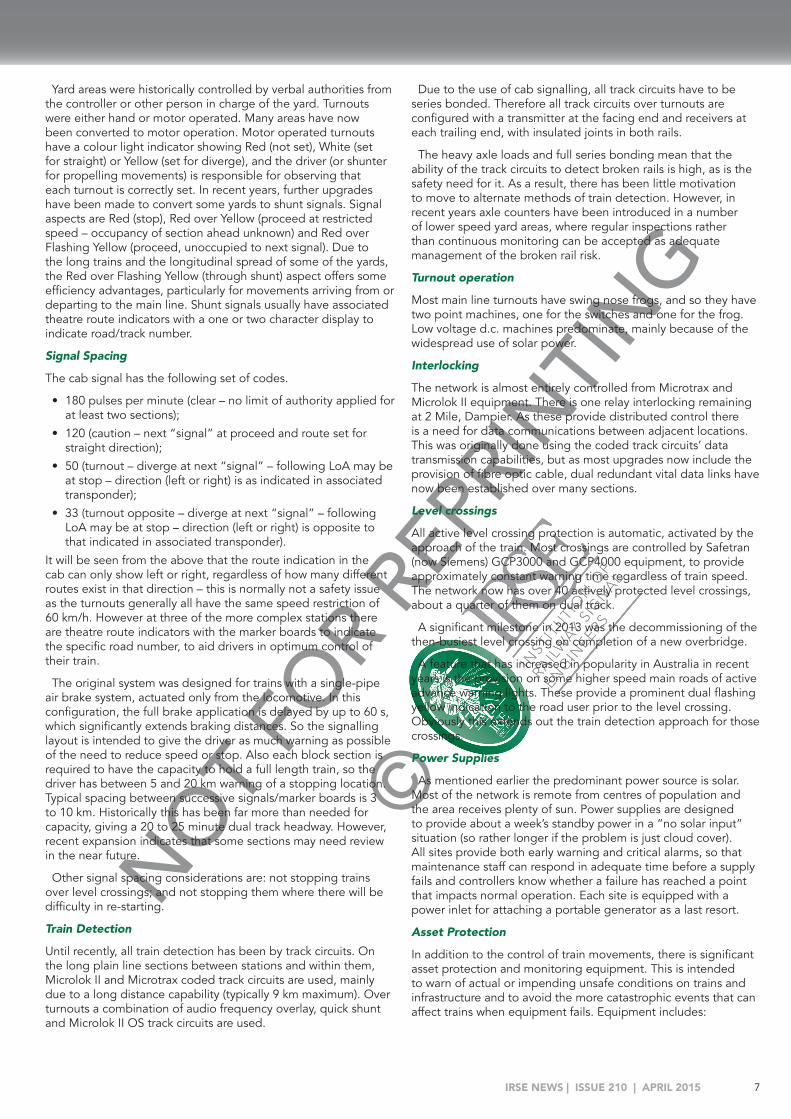
Yard areas were historically controlled by verbal authorities from the controller or other person in charge of the yard. Turnouts were either hand or motor operated. Many areas have now been converted to motor operation. Motor operated turnouts have a colour light indicator showing Red (not set), White (set for straight) or Yellow (set for diverge), and the driver (or shunter for propelling movements) is responsible for observing that each turnout is correctly set. In recent years, further upgrades have been made to convert some yards to shunt signals. Signal aspects are Red (stop), Red over Yellow (proceed at restricted speed – occupancy of section ahead unknown) and Red over Flashing Yellow (proceed, unoccupied to next signal). Due to the long trains and the longitudinal spread of some of the yards, the Red over Flashing Yellow (through shunt) aspect offers some efficiency advantages, particularly for movements arriving from or departing to the main line. Shunt signals usually have associated theatre route indicators with a one or two character display to indicate road/track number.
Signal Spacing
The cab signal has the following set of codes.
• 180 pulses per minute (clear – no limit of authority applied for at least two sections);
• 120 (caution – next “signal” at proceed and route set for straight direction);
• 50 (turnout – diverge at next “signal” – following LoA may be at stop – direction (left or right) is as indicated in associated transponder);
• 33 (turnout opposite – diverge at next “signal” – following LoA may be at stop – direction (left or right) is opposite to that indicated in associated transponder).
It will be seen from the above that the route indication in the cab can only show left or right, regardless of how many different routes exist in that direction – this is normally not a safety issue as the turnouts generally all have the same speed restriction of 60 km/h. However at three of the more complex stations there are theatre route indicators with the marker boards to indicate the specific road number, to aid drivers in optimum control of their train.
The original system was designed for trains with a single-pipe air brake system, actuated only from the locomotive. In this configuration, the full brake application is delayed by up to 60 s, which significantly extends braking distances. So the signalling layout is intended to give the driver as much warning as possible of the need to reduce speed or stop. Also each block section is required to have the capacity to hold a full length train, so the driver has between 5 and 20 km warning of a stopping location. Typical spacing between successive signals/marker boards is 3 to 10 km. Historically this has been far more than needed for capacity, giving a 20 to 25 minute dual track headway. However, recent expansion indicates that some sections may need review in the near future.
Other signal spacing considerations are: not stopping trains over level crossings; and not stopping them where there will be difficulty in re-starting.
Train Detection
Until recently, all train detection has been by track circuits. On the long plain line sections between stations and within them, Microlok II and Microtrax coded track circuits are used, mainly due to a long distance capability (typically 9 km maximum). Over turnouts a combination of audio frequency overlay, quick shunt and Microlok II OS track circuits are used.
Due to the use of cab signalling, all track circuits have to be series bonded. Therefore all track circuits over turnouts are configured with a transmitter at the facing end and receivers at each trailing end, with insulated joints in both rails.
The heavy axle loads and full series bonding mean that the ability of the track circuits to detect broken rails is high, as is the safety need for it. As a result, there has been little motivation to move to alternate methods of train detection. However, in recent years axle counters have been introduced in a number of lower speed yard areas, where regular inspections rather than continuous monitoring can be accepted as adequate management of the broken rail risk.
Turnout operation
Most main line turnouts have swing nose frogs, and so they have two point machines, one for the switches and one for the frog. Low voltage d.c. machines predominate, mainly because of the widespread use of solar power.
Interlocking
The network is almost entirely controlled from Microtrax and Microlok II equipment. There is one relay interlocking remaining at 2 Mile, Dampier. As these provide distributed control there is a need for data communications between adjacent locations. This was originally done using the coded track circuits’ data transmission capabilities, but as most upgrades now include the provision of fibre optic cable, dual redundant vital data links have now been established over many sections.
Level crossings
All active level crossing protection is automatic, activated by the approach of the train. Most crossings are controlled by Safetran (now Siemens) GCP3000 and GCP4000 equipment, to provide approximately constant warning time regardless of train speed. The network now has over 40 actively protected level crossings, about a quarter of them on dual track.
A significant milestone in 2013 was the decommissioning of the then-busiest level crossing on completion of a new overbridge.
A feature that has increased in popularity in Australia in recent years is the provision on some higher speed main roads of active advance warning lights. These provide a prominent dual flashing yellow indication to the road user prior to the level crossing. Obviously this extends out the train detection approach for those crossings.
Power Supplies
As mentioned earlier the predominant power source is solar. Most of the network is remote from centres of population and the area receives plenty of sun. Power supplies are designed to provide about a week’s standby power in a “no solar input” situation (so rather longer if the problem is just cloud cover). All sites provide both early warning and critical alarms, so that maintenance staff can respond in adequate time before a supply fails and controllers know whether a failure has reached a point that impacts normal operation. Each site is equipped with a power inlet for attaching a portable generator as a last resort.
Asset Protection
In addition to the control of train movements, there is significant asset protection and monitoring equipment. This is intended to warn of actual or impending unsafe conditions on trains and infrastructure and to avoid the more catastrophic events that can affect trains when equipment fails. Equipment includes:
NOT FOR R
EPRIN
TING
©
IRSE NEWS | ISSUE 210 | APRIL 20158
MARCH TECHNICAL PAPER• Dragging equipment detectors spaced at 3 to 5 km intervals;• Hot wheel and hot bearing detectors spaced between 20 and
50 km dependent on intensity of operation;• Stream flow detectors at major culverts and bridges;• Wheel impact detectors on approach to the ports;• Bearing acoustic monitor, to assist in longer term monitoring
and predictive maintenance of axle bearings.Other Rail Movements
Apart from the trains on the network there are many track maintenance and Hi-Rail (road-rail vehicle) movements to support maintenance activities. Following a number of incidents where incorrect protection was applied, protection prematurely removed or vehicles had moved outside their protection limits, a non-vital GPS based system was introduced to monitor all Hi-Rail and track machine movements and display them on the train controller’s screen (by mapping their location to the existing track circuits). The system will then also alarm if any of the above undesired events occurs and prevent conflicts at the train control system level. While this is not a safety-critical application it assists greatly in reinforcing procedures and mitigating human error.
South Australia and Northern TerritoryThe interstate standard gauge line is owned by ARTC. The network is not fitted with ATP. However Advanced Train Management System (ATMS), a system similar to Positive Train Control, has completed a proof of concept phase, and is now being tested for two years on a section of ARTC’s rail network in South Australia between Whyalla and Port Augusta.
Other lines (mainly for grain traffic), are operated by Genesee and Wyoming Australia Pty Ltd., a North American based corporation. This includes the 2200 km long line from Tarcoola to Darwin. See “Signalling the Alice Springs to Darwin Railway”, McDonald W., IRSE, 2003.
Public Transport Services (PTS), a South Australian government agency, provides passenger rail services within Adelaide as part of the Adelaide Metropolitan Public Rail Network (AMPRN), see http://bit.ly/1BvQHg5
Adelaide Metropolitan Public Rail Network (AMPRN)The major change to the signalling for the Adelaide Metropolitan area has come from electrifying at 25 kV and related extensions to the network and grade separations. These works included supply of 22 three-car sets of new A-City Class 4000 electric trains. The first was delivered on 19 July 2013, and electric passenger services from Adelaide to Seaford commenced on 23 February 2014, supplemented by the existing diesel fleet.
Originally all lines were to be electrified at 25 kV, but complete electrification deployment has been rescheduled due to budget problems. See: http://bit.ly/1vj339n
South Australia historically has been early to adopt new signalling technologies, including the first SSI in Australia (in Adelaide), WESTRACE Mk 1 (at Dry Creek) and computer based CTC. Continuing this tradition the project sees, along with the immunisation of the signalling system, introduction of WESTLOCK and WESTRACE II interlocking with integrated Frauscher FAdC axle counters and ETCS Level 1.
As with all modern signalling systems, data communications are crucial. The system uses Ethernet, with a fibre optic cable in a ring architecture. Bearer diversity is provided by using Optical Ground Wire (OPGW) fibre optic cable. The new lineside signalling uses a modular signalling approach, with new LED tilting signals, Computer-Based Interlocking, and fibre optic communications to ensure compatibility with the new overhead electrification system. A new train control system is being installed across the entire network. The Seaford and Belair tracksides have been fitted with ETCS Level 1 LEU ready for system commissioning when the rolling stock is fitted. See: http://bit.ly/1ASVwPp
Overview of the AMPRN Signalling SystemAll main line signals on the Adelaide network are of the single head, multi-aspect type, using either incandescent lamps or LEDs. All low speed and ground shunt signals are of the position light type.
Signalling is based predominantly on the route signalling system with different aspects (Red, Yellow, Flashing Yellow and Green main aspects and White for subsidiary signals) to indicate the extent and type of movement authority.
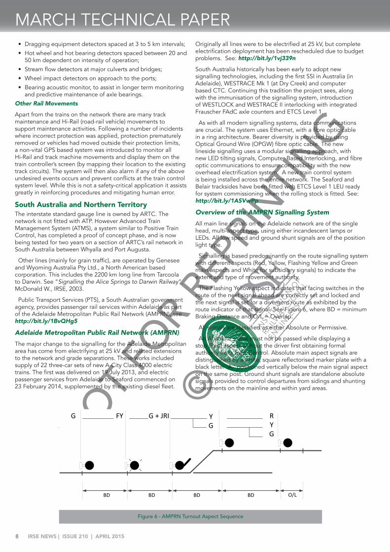
The Flashing Yellow aspect indicates that facing switches in the route of the next signal ahead are correctly set and locked and the next signal is set for a divergent route as exhibited by the route indicator of that signal. See Figure 6, where BD = minimum Braking Distance and O/L = Overlap.
All signals are classified as either Absolute or Permissive.
An Absolute signal must not be passed while displaying a stop (Red) aspect without the driver first obtaining formal authority from Train Control. Absolute main aspect signals are distinguished by a white, square reflectorised marker plate with a black letter ‘A,’ positioned vertically below the main signal aspect on the same post. Ground shunt signals are standalone absolute signals provided to control departures from sidings and shunting movements on the mainline and within yard areas.
G
O/LBDBDBDBD
FY G + JRI RYG
YG
Figure 6 - AMPRN Turnout Aspect Sequence

NOT FOR R
EPRIN
TING
©
IRSE NEWS | ISSUE 210 | APRIL 2015 9
Ground shunt signals display either a stop aspect (one red and one white light) or a proceed aspect (two white lights in a diagonal configuration). Ground shunt signals may be displayed in conjunction with a stencil route indicator where more than one route exists. Ground shunt signals provide authority to the driver to proceed at low speed being prepared to stop clear of any obstruction.
Absolute main aspect signals may be fitted with a position light subsidiary signal mounted directly below the “A” marker plate, on the same post. These signals display two white lights in a diagonal configuration and provide authority to the driver to enter an occupied section of track at low speed being prepared to stop clear of any obstruction.
A Permissive signal is a main-aspect signal which may be passed while displaying a stop (Red) aspect without the driver first obtaining formal permission from Train Control. Regulations require that the train be brought to a stand at such a signal for at least 1 minute and then proceed past the stop signal in accordance with PTS Common General Operating Rules. Permissive signals are distinguished by a round, white reflectorised marker plate with a black letter ‘P,’ positioned diagonally below the main signal aspect. Permissive signals can display Red, Yellow, Flashing Yellow or Green aspects. They are generally automatic signals with no control facility, although under location-specific operational requirements Train Control is able to replace certain Permissive signals to Red.
Automatic Warning System
An advisory Automatic Warning System (AWS) is provided for main line signals. This presents the driver of a suitably equipped train with an audible and visual alert to warn that the train is approaching a caution or stop aspect. If the driver does not acknowledge this alert within a specified time, emergency braking is automatically applied.
The trainborne equipment is activated by magnets positioned between the rails. The system features three magnet types:
• A permanent magnet used to “arm” the on-board equipment;
• An electromagnet used to cancel arming of the on-board equipment when the protected signal is displaying a Green aspect;
• A suppressed permanent magnet energised only as required, to prevent arming of the onboard equipment when a train traverses a permanent magnet in an opposite direction to which the permanent magnet applies (e.g. for bi-directional running).
New installations of AWS magnets are nominally located at a distance of 125 m on the approach to the associated signal for all line speeds up to 110 km/h. The exact positioning of the equipment takes into consideration that the driver must be able to sight the signal aspect at the time the warning is received by the trainborne receiver, but also for not less than 4 s at the permissible track speed.
For example, where sighting is poor and line speeds are lower, the AWS is positioned closer to the signal, at the point where the signal becomes visible and also considering this location not to be less than 4 s at the prevailing line speed. On bi-directional lines, AWS magnets are provided for both directions of movement.
VictoriaThe interstate standard gauge lines are leased to the Australian Rail Track Corporation. Broad gauge (and some standard gauge), branch lines are owned by the Victorian Government owned
Victrack. The Melbourne urban system is managed by the Victorian Government authority Public Transport Victoria and is operated by MTM, with regional services operated by V/Line.
The 2002 Convention paper provides an overview of Victorian systems. The Victorian Rail Industry Operators’ Group Standards (VRIOGS) are another useful resource.
Regional Rail Link The Regional Rail Link (RRL) project has seen extensive changes, to separate regional (V/Line) traffic from Geelong, Ballarat and Bendigo from metropolitan (MTM) services, as the lines approach Southern Cross Station (formerly Spencer St Station), from the west of Melbourne. To increase capacity and reliability, some 90 km of new lines have been delivered, with six work packages from three different suppliers that included modifications to existing signalling and control systems and new signalling systems. See: http://bit.ly/1G3j9oC
Geographically, separation of the two operations has not been easy. MTM and V/Line shared tracks, signalling and platforms at the main stations of Flinders Street and Southern Cross. However space was found to add two separate lines through the metropolitan area to a junction at Sunshine, about 15 km from the city. A new double track line some 30 km long was built there in a green field site, to join up with the country main line to Geelong. It has taken four years to complete this complicated project, with many staged works including track diversions, temporary tracks, and areas of dual trackwork to accommodate standard gauge trains.
The new RRL lines and all V/Line signalling are controlled by new equipment in an existing control centre called CENTROL, in the heart of Melbourne.
Of note has been the gradual divergence between the two operators in their choice of signalling subsystems.
Sub System V/Line MTM
Train detection Axle Counters Track circuits, HVI, JTC
Points M23ANote both blades are now independently
detected. Previously only one blade was detected and the correct detection relied on the mechanical integrity of the layout.
Train Protection TPWS enforcement and over speed detection at all signals capable of showing a medium
speed (40 km/h)
Train Stop
Interlocking CBI (Alstom Smartlock, Siemens WESTLOCK and
GE Electrologic)
CBI plus a large number of relay
Signals Tricolour LED, fixed masts
LED with tilting masts
This divergence has led to revised principles and changes to previously common standards. For example, Victoria uses speed signalling with full braking overlaps. Both operators follow these principles, MTM with train stops and V/Line with TPWS. As V/Line uses an overspeed TPWS at medium speed signals and thus enforces a 40 km/h speed, their full braking overlap at the stop signal is only the distance the train needs to stop from 40 km/h,

NOT FOR R
EPRIN
TING
©
IRSE NEWS | ISSUE 210 | APRIL 201510
MARCH TECHNICAL PAPERso the overlap is shortened, which allows a better headway.
This principle is applied throughout RRL and is treated as four-aspect signalling. Note that V/Line now specify a full braking overlap - as being the distance whose length is equal to the braking distance (for the appropriate approach speed) plus 10%. So principles common in Europe are not applied; for example, at a left hand double junction, if a train is trailing through the junction from the left, the facing points are not set to the left as a trapping protection as it is assumed that the opposing train will have been stopped before the junction if it had passed the junction signal at Red. This divergence is likely to become more marked in future with plans to introduce high capacity signalling.
TasmaniaRail in Tasmania is owned and operated by Tasmanian Railway Pty Ltd (TasRail), a Tasmanian Government-owned rail company established in December 2009. Current TasRail train control operations are based on Track Warrant Control, using verbal radio communications to grant authorities to trains and track vehicles. TasRail is implementing an Advanced Network Train Control System (ANCS), where the upgraded Train Control System is based on North American Positive Train Control (PTC), and combines a graphical Train Control Centre with electronic communication to onboard computers equipped with display and GPS location. For more details see:
“Upgrading the TasRail Train Control System”, Atchison et al., IRSEA 2013; and also http://bit.ly/1vGs2hK
New ZealandAuckland ElectrificationThe Auckland network was electrified at 25 kV in 2014, and re-signalled including bi-directional signalling and ETCS Level 1 ATP. See IRSE NEWS Issue 207 for full details.
Local Lockout ZonesLocal lockout zones providing enhanced worksite protection are a feature in the Auckland area. These are areas where signals are interlocked, using a local control to prohibit train movements, in order to allow maintenance staff to work safely. In addition signals must be limited to displaying a low speed aspect when a lockout zone is reversed in its overlap.
Lockout zones require a release from the control centre before they can be reversed in the interlocking. Intermediate signals must show Stop and Stay if the overlap extends into the lockout zone. Once the lockout zone is given, all routes through it are locked normal. Routes with overlaps in the lockout zone can still be set. The lockout zone for these routes is tested at main aspect level. The Maintainer claims the lockout zone, and it then becomes fully reverse.
The lockout zone cannot be taken back by the Signaller until the Maintainer hands it back by normalising the lockout zone switch. Once this is done the Signaller may normalise the zone and normal traffic movements can then take place. Points within the lockout zone are not locked when the zone is reverse, as they may be required to move as part of the maintenance activities, or if they are in the overlap of a signal.
The lockouts provide trackside staff with a safety-critical mechanism to protect themselves co-operatively, and the ability to place a physical ‘tag out’ padlock on their protection once given (see Figure 7).
New South WalesIn NSW the five-year re-organisation cycle began anew on 1 July 2013, with the separation of RailCorp into Sydney Trains, NSW Trains and the creation of the Transport for NSW (TfNSW) – Asset Standards Authority and a Projects group. Sydney Trains and NSW Trains operate and maintain, and TfNSW delivers major projects. The RailCorp signalling systems described in IRSE NEWS 163 have not yet changed significantly.
The defined Interstate Network and Hunter Valley lines are leased to ARTC, which now also manages the Metropolitan Freight Network, including the Southern Sydney Freight Line, and the dedicated freight line to Port Botany. Other freight separation works are in progress at North Strathfield, and on the Main North Line.
Regional branch lines (the Country Rail Network) are owned by a NSW Government agency, Transport for NSW, and maintained by John Holland Rail.
Major Metropolitan Passenger Network projects have included new track, turnbacks, and stabling facilities for capacity and reliability improvements, and the new South West Rail Link at Glenfield due to enter revenue service in 2015.
As for Automatic Train Protection, a project to install ETCS Level 1 as an overlay, retaining lineside signals, is currently in progress.
TfNSW has commenced the North West Rail Link which is essentially a separate Metro line, comprising conversion of the present Epping - Chatswood rail line and the construction of a new line from Epping to Cudgegong Road. These Sydney Rapid Transport lines are to use automatically operated single deck rolling stock with CBTC signalling and control systems. See: http://bit.ly/17gtWzC
Hunter Valley - Simultaneous Entry to Crossing Loops The following section is an abridged version of the cunning use of additional signals in the Hunter Valley to permit simultaneous train entry at CTC passing loops while minimising expensive construction of additional track. ARTC NSW standards state that trains must stop at home signals when crossing at loops. Application of these standards severely reduces throughput by increasing transit times at crossings.
Simultaneous (SIM) Entry into CTC passing loops provides operational advantages by:
• not stopping trains at home signals – reduces crossing time;• minimising down time for level crossings in the single line
section.
Figure 7 - Lockout Zone at Papakura

NOT FOR R
EPRIN
TING
©
IRSE NEWS | ISSUE 210 | APRIL 2015 11
The standard SIM arrangements require additional track construction, with starting signals located 300 m from the clearance points to provide the required overlaps. The modified approach, still providing a 300 m overlap, has only 34 m of track construction with an extra four signals, track circuits and overlay timing tracks.
The standard states, “The home signal shall be provided with an overlap immediately in advance of the main and loop starting signals.” It further details the requirement: “The 300 m overlap entirely within the crossing loop and clear of the clearance point for the other path through the crossing loop ... will allow for the clearing of both home signals for simultaneous entry to the loop line and the main line. The aspect sequence is to be appropriate for the path to the stop signal with a 300 m overlap. The points shall be set to direct any conflicting movement to an alternate path.” Note that a low speed subsidiary signal overlap is specified as 100 m. Also, “The Low Speed aspect is to be considered a running signal aspect although it may be time approach cleared and not part of the running aspect sequence.” So adding extra signals fitted with low speed aspects and the
associated timing tracks complies with these principles.
When a train is signalled into either the Loop or Main to cross, the home signal controlling the entrance to the loop is provided with a 300 m non-shared overlap between the Loop/Main Home Signal and the clearance point (see Figure 8). An overlap is provided immediately beyond the stop signal to which the warning aspect applies. This overlap must be vacant for the home signal to clear to caution. When the train approaches the new signals, the train is speed checked by approach timing. The new signal displays a low speed signal aspect:
• when the timing sequence is complete, • and the train is proved to have reduced speed to 25 km/h or
lower (estimated by the timing track), • and the 100 m overlap is unoccupied (see Figure 9, where
BOL = Band of Lights).For a full description see Malaviya A and Sweeny D: “Economic Signalling Enhancement - Providing capacity improvements in a mixed traffic environment”, IRSEA 2014.
UpHome
Up Main Starting
Down Main
Starting
Down Loop
Starting
Up Loop Starting
DownHome
R/RR/R
R + LSp R/R
R +LH
BOL
YR/R R/R
R + LSpR/R
Timing Tracks
BOL = Band of Lights
UpHome
Up Main Starting
Down Main
Starting
Down Loop
Starting
Up Loop Starting
DownHome
UpHome
Up Main Starting
Down Main
Starting
Down Loop
Starting
Up Loop Starting
DownHome
Additional Signals Fitted With Low Speed (LSp)
apsect
Figure 9 - Modified SIM Operation and Aspect Sequences
Figure 8 - Standard and Modified SIM Crossing Arrangements

NOT FOR R
EPRIN
TING
©
IRSE NEWS | ISSUE 210 | APRIL 201512
MARCH TECHNICAL PAPERFINAL COMMENTSIn Australasia there is no harmonisation of signalling standards and principles. For example, a flashing yellow aspect displayed to drivers means:
• in Queensland – maximum speed 40 km/h, possible zero overlap;
• in Adelaide - diverging junction ahead;• in New South Wales - single head signals - Medium, next signal Caution, double head Signals - Preliminary Medium, next signal
Medium;• in Auckland – Advance Caution (next signal Caution).
Perhaps with the wider use of cab signalling systems such differences will become irrelevant?
All the major cities have similar issues with increasing patronage, and the freight railways need more efficient operations, leading to the need for clever application and implementation of more
advanced signalling systems. There has been a steady increase in investment in rail infrastructure throughout Australia and New Zealand since 2002. Let us hope this trend continues!
ACKNOWLEDGEMENTSThe author is grateful to the following people for their assistance in the preparation of this paper: Tony Godber, Malcolm Menadue, Mayank Jain, Charles Page, John Skilton, Tony Howker, George Nikandros, Paul Huth, and Ian Joyner.
REFERENCES“Australasian Signalling”, Symons Peter, IRSE Australasia,
13 March 2002. “Fundamentals of Signalling a Heavy Haul Railway”,
Godber Tony, IRSE Australasia, March 2007, “Signalling Challenges of the Sector 2 Timetable Queensland
Rail”, Joyner Ian and Wieland Maurice, Brisbane Local IRSE Meeting 2014.
YOUNGER MEMBERS PAPER
Why Organisations Need to Think About Reliability in the 21st CenturyBy Harry Munro BEng (Hons) AMIMechE
“When things break, it’s not the actual breaking that prevents them from getting back together again. It’s because a little piece gets lost — the two remaining ends couldn’t fit together even if they wanted to. The whole shape has changed.”- John Green, David Levithan and Will Grayson
A MATTER OF IMPORTANCEReliability is one of the fundamental pillars to a high level of quality in an organisation. It could be argued that the new industrial revolution is held together by the glue of high quality and reliability.
In fact, out of all the ‘ilities’ (non-functional requirements) which constitute a system, research from MIT [1] shows that the top five terms which appear most in journal articles are, in this order:
1. Quality;2. Reliability;3. Safety;4. Flexibility;5. Robustness.
Reliability is therefore becoming quite important. Not just from a cost point of view but also from a social and ethical point of view. When a train is delayed on the way home from work a passenger will not be able to spend as much time with their family that evening or the regular act of commuting to work may take longer than expected as a result of routine maintenance (Figure 1).
The problems do not stop here, as the quote at the beginning of this article alludes to, when failures occur a system is not the same after fixing it. Failures cause a ripple effect that extends beyond the accounting books. A delayed train might cause some customers to refund their tickets, but worse, more customers will believe that the train service is poor quality, and rightly so if the delays are frequent. This could result in a modal shift to alternative forms of transport. Reliability is inseparably
linked to emotions and feelings about a product, organisation or service.
The Mayor of London has set a target to reduce delays on London Underground’s serviced by 30% from 2011 to this year [2]. The fact that this has been made a keystone of an organisation like London Underground’s strategy highlights the importance of reliability to the general public. One example of a company which failed to uphold reliability was Railtrack. This organisation was responsible for Britain’s rail infrastructure between 1999 and 2003. During that period delays nearly doubled and Railtrack subsequently went into administration [3]. It was acquired by Network Rail which has subsequently reduced delays since, but not without damage to the reputation of Britain’s railways.
Figure 1- Rush hour queue at Brixton Underground station, London, caused by escalator maintenance

NOT FOR R
EPRIN
TING
©
IRSE NEWS | ISSUE 210 | APRIL 2015 13
0
50
100
150
200
250
Train doorsjammed due
to debris
Customersholding
open doors
CCTV failure Startersignal failure
Brakesystemsfailed
OtherFailures
Risk
Prio
rity
Num
ber
Figure 3 – An example Pareto chart of risks
RELIABILITY COSTSPerfect reliability is an impossibility, as the costs to achieve it rise to the point of diminishing returns, and like training to run a mile, new gains become increasingly more marginal and require more effort for the reward.
Reliability is an aspect of a product or service so directly linked to the customer, and thus reputation, that any organisation taking measures to ensure success does so at its benefit. Organisations need to think about not just the frequency of their failures, but also the severity of them, and any control and mitigating factors that can be put in place.
Product development is a good example of why it is important to target reliability as early as possible in the life cycle. There is a concept known as the “rule of 10” when designing products. This rule states that at each step the product gets closer to the customer, the cost of correcting a failure is 10 times that of the last step [4]. These steps are arbitrary, and there is no one size fits all approach. Figure 2 is a suggestion for one such framework:
The next question is how to improve reliability. Traditionally a prototype of the product or service is produced, tested, observed where and how it does not work, and then the failures corrected. Unfortunately this approach is no longer competitive. If waiting until the product is somewhat developed before testing for failures, then having to make changes at step 3 or 4 is very costly! So the corrections could be costing three to four times as much as they would do if corrected earlier on. How to correct failures early on in the product cycle is as much an art as a science. However, there exist failure-free design principles which should be employed; one such tool is failure modes and effects analysis (FMEA).
FAILURE MODES AND EFFECTS ANALYSISFailure Modes and Effects Analysis (FMEA) is a team-based exercise where risks and failures are brainstormed. The group systematically evaluates each risk by scoring how often they believe it will occur, how severe the impact is when it does occur and finally the likelihood that the problem will be detected and corrected before it manifests into a problem for the customer. The philosophy of this approach is that the organisation can direct its finite resources to the greatest risks. It is thus essential that following the FMEA, the risks are sorted and prioritised. A Pareto chart can be created with the results, which forms a simple but effective communication tool. An hypothetical example is shown in Figure 3.
There are three broad types of FMEA:
1. System FMEA;2. Design FMEA;3. Process FMEA.The system level FMEA, which provides a high level view,
should be carried out by the original equipment manufacturer (OEM) or the organisation responsible for delivering the final system, and should be delivered to the customer or operator. Operating organisations responsible for the deployment of
multiple different assets (e.g. London Underground and Network Rail) should carry out higher level system FMEAs to assess risks between the interactions of different systems working together.
Responsibility for the design FMEA(s) should be given to the organisation(s) most responsible for the design and development process of subsystems (and the subsystems of subsystems). These would usually be the tier 1 and tier 2 suppliers.
Process FMEA(s) should be carried out by the manufacturer(s), in order to reduce the risk of producing a low quality product and therefore not meeting the specifications of the design. Manufacturers will include the OEMs, usually in the case of assembly manufacturing. However the responsibility for process FMEAs will also rest with tier 1 and tier 2 suppliers since they will usually carry out the majority of the manufacturing.
The irony of a brilliantly designed highly reliability product or service is that the credit rarely goes to the engineers involved in designing the system up front. Thanks to our negativity bias, what works well often does not get the attention it deserves! However one beauty of FMEA is that risks are documented, meaning that organisations can learn. These risks are quantified and are a demonstration of reliability improvement, it allows organisations to assess risk of their product or service before implementation and it serves as an excellent collaboration tool between supplier and customer. The FMEA also provides preliminary data for modelling and simulation purposes.
CONCLUSIONReliability improvement is a challenge to achieve in any organisation; it may require a change of thought process in the culture, which can take time and education. It will certainly require full commitment from management at the top. Organisations need to dedicate energy to its pursuit, or risk exposing themselves and their customers to damaging failures which can slowly erode the balance book, or catastrophic failures which can destroy their reputation overnight.
REFERENCES1. Weck, O L, Roos D., & Magee, C L (2011). Engineering
Systems. Massachusetts Institute of Technology.2. Transport for London. (2013). Business Plan. London.3. National Audit Office. (2008). Reducing passenger rail delays
by better management of incidents. London: The Stationery Office.
4. Carlson, C S (2012). Effective FMEAs. Hoboken, New Jersey: John Wiley and Sons.
State of Product Cost Change / ImpactConcept 10£ Words, ideas and concept designsDesign 100£ Technical documentation changeDevelopment 1,000£ Physical prototype design changeValidation 10,000£ Testing programme needs to be adjustedFull-production 100,000£ Change to a factory in full-productionCustomer 1,000,000£ Reputation impact, recalls, liability
Figure 2 - Suggested table showing the cost of correcting failures

NOT FOR R
EPRIN
TING
©
IRSE NEWS | ISSUE 210 | APRIL 201514
IRISH SECTION PAPER
Signalling with Hindsight - from Clapham to Finaghy and Beyond!By Colin McVeaSignal Maintenance Engineer, Northern Ireland Railways
This paper was originally produced and presented at the formation of the Irish section IRSE in December 2014. It was written to give an insight of the changes which have occurred within Northern Ireland Railways (NIR) signalling, detailing the reasons why. The changes and reasons are similar to those that occurred within BR, a decade earlier, and the lessons learnt are still as relevant today (and beyond)
So what can be learnt?
Signalling has changed greatly over the past decade, the scope of engineers involved in developing modern signalling systems has increased significantly, and now covers a wider range of competencies than ever before. Telecommunications, radio transmission, computer programming as well as fleet engineering are all involved in the process of producing modern railway control systems, and to further complicate this, these individual systems need to be interfaced with each other to produce a safe, efficient, maintainable and reliable system. Those engineers new to signalling will comply with the regulations without much thought, whilst those more experienced (older) will know the reasons behind them. Knowing how offers some comfort, but knowing why gives a fuller understanding and as such provides a further barrier. It is hoped this paper gives some insight as to why, and helps create a better understanding.
There is a responsibility placed upon everyone in the process of providing a signalling system, but those that feature most when incidents or accidents occur are those engineers which complete the final task before allowing signalling systems to resume, or begin. This paper highlights the vulnerability and responsibility of these engineers, as well as the possible consequences of their actions.
This paper looks at two railway accidents of quite different magnitude and it links some of the common findings and recommendations. It is not aimed at criticising any individual or company, but to capture a flavour of the culture that existed at both times, the circumstances which led to both accidents, and the changes which have occurred since. The evidence used is based upon the accident report completed by Sir Anthony Hidden, a NIR report by an accident investigation panel, along with personal experiences of the author. It is hoped it…
• provides some insight into the safety culture that existed within both companies and the wider industry;
• explains how the culture contributed to events leading up to the final errors that occurred;
• explains the mitigating measures which exist today to prevent similar occurrences;
• reminds Railway Engineers, of all ages of the responsibilities placed upon them;
• identifies the possible consequences of not meeting these.Whilst writing this paper I was hoping to keep clear of any academia, there are a great number more of academics, particularly within the IRSE, who can offer a lot more than me. The majority of this paper is based upon my personal experiences, rather than any academic research, although I have included Reason’s “Swiss Cheese model”- which helps
put some theory behind the circumstances of both accidents. I think it is suitable due to the simplicity and visual representation it provides, especially when looking back with hindsight, and comparing systems in place today, to those which existed then.
I had originally placed this section regarding Reason’s “Swiss Cheese Model” at the end of this paper, but again with hindsight I believe in providing the reader with this knowledge at the beginning, it gives a greater opportunity to identify some of the “underlying causes” that existed before both accidents occurred.
Reason produced what is referred to as the “Swiss Cheese Model”. Every step in a process has the potential for failure, to a varying degree. Consider the holes to be opportunities for a process to fail, and each of the slices as “defensive layers” in the process. An error may allow a problem to pass through a hole in one layer, but in the next layer the holes are in different places, and the problem should be caught. Each layer is a defence against potential error impacting the outcome. Each slice of cheese is an opportunity to stop an error. The more defences you put up, the better. Also the fewer the holes and the smaller the holes, the more likely you are to prevent the circumstances that lead to accidents. This is shown in Figures 1 and 2 below.
Accidents are caused by active failures or latent conditions which can lead to human error or violations.
Figure 1 - Reason’s Swiss Cheese Model
Figure 2 - Reason’s Layers of Defence
Hazards
Accident
Some holes due to active failures
Other holes due to latent conditions
HazardsSome holes due to
active failures
Other holes due to latent conditions

NOT FOR R
EPRIN
TING
©
IRSE NEWS | ISSUE 210 | APRIL 2015 15
Active failures are the acts or conditions precipitating the incident situation. They usually involve the front line staff; the consequences are immediate and can often be prevented by design, training or operating systems.
Latent conditions are the managerial influences and social pressures that make up the culture (“the way we do things round here”), influence the design of equipment or systems, and define supervisory inadequacies. They tend to be hidden until triggered by an event.
We are often “set up to fail” by the way our brain processes information, by our training, through the design of equipment, and the procedures and even through the culture of the organisation we work for.
Latent failures are made by people whose tasks are removed in time and space from the operational activities, e.g. designers, decision makers and managers. Latent failures are typically failures in Health and Safety management systems:
• Poor design of plant and equipment;• Ineffective training;• Inadequate supervision;• Ineffective communications;• Inadequate resources (e.g. people and equipment);• Uncertainties in roles and responsibilities.
Latent failures are usually hidden within an organisation until they are triggered by an event likely to have serious consequences. This paper highlights some of the latent failures that existed before both accidents that occurred.
Typical examples of immediate causes and contributing factors for human failures are shown in Figure 3.
Job factors:
• Illogical design of equipment and instruments;• Constant disturbances and interruptions;• Missing or unclear instructions;• Poorly maintained equipment;• High workload;• Noisy or unpleasant working conditions.
Individual factors:
• Low skill and competence levels;• Tired staff;• Bored or disheartened staff;• Individual medical problems.
Organisation and management factors:
• Poor work planning, leading to high work pressure;• Lack of safety systems and barriers;• Inadequate responses to previous accidents;• Management based upon one-way communication;• Deficient co-ordination and responsibilities;• Poor management of health and safety; • Poor health and safety culture.
At 08:10 on the morning of Monday 12 December 1988, a crowded commuter train ran head-on into the rear of another which was stationary in a cutting just South of Clapham Junction station in the UK. After that impact the first train veered to its right and struck a third oncoming train. As a result of the accident 35 people died and nearly 500 were injured, 69 of them seriously.
Anthony Hidden QC was appointed by the Secretary of State to complete a formal investigation of the accident and the causes and of the circumstances,. Their report was presented to Parliament in November 1989. The report had 231 pages and made some 93 recommendations
At 06:40 the morning of 7 April 1998, a goods train carrying cement collided at low speed into the rear of another goods train carrying Guinness, the collision occurred some 200 metres on the Belfast side of Finaghy station, the driver and guard escaped with relatively minor injuries. The general layout of the area is shown in Figure 4.
The accident was caused by the omission of the track circuit from the signal circuitry (149),this occurred during work to facilitate track upgrade, the modifications installed removed the protection offered by the occupation of the associated track circuit, and prevented the protecting signal from displaying the correct aspect. (Figure 5)
An enquiry panel was appointed by Translink, the remit was to report the immediate causes, as well as root cause(s) of the incident whilst making necessary recommendations to prevent re-occurrence. The report was completed on November 1998 and consisted of 25 pages, which made a total of seven recommendations.
The circumstances surrounding these events are almost identical, in that human error on the part of the signalling technicians removed the protection offered by the interlocking, although the severity of the incidents greatly differed. (Note: the severity of outcome is often the main distinguishing feature between similar accidents).
Mr Hemingway and I were both employed as signalling technicians by our respective companies, and in that role, we made the final errors which led to both accidents. We were responsible for changing the safety culture within both railway companies, not because we recognised the deficiencies within both our departments, and were diligent enough to point these out, but because we both made mistakes. These in turn led to investigations, and it was from these that improvements were made.
According to the report into the Finaghy incident:
“the expectation of the Technician Officer (TO) was too great, from his behaviour it would appear that he was not capable of responding to the responsibility which was placed upon him. To fulfil the role expected of him he would have needed to have thought intelligently about the modifications and the tests which he would have needed to carry out. This he did not do, carrying out the allocated work without full consideration of what he was doing.”Figure 3 - Typical causes and failures leading to an accident
ACCIDENT
Human failures
Latent errors Unsafe plant/condition
Unsafe act
Failure to recoversituation
INCIDENT
Failure ofmitigation
Organisation
Person Job
Performance influencing factors

NOT FOR R
EPRIN
TING
©
IRSE NEWS | ISSUE 210 | APRIL 201516
IRISH SECTION PAPER
“Not capable of responding to the responsibility placed upon him”, again looking back to the occasion of the accident, I was a maintenance Technician Officer, who was capable of responding to failures. Occasionally I was involved in new works, these tasks required and included, modification of wiring under instruction, and verification of signalling equipment on the ground, which usually entailed standing at some remote location, and reporting back the aspect being displayed, or the lie of points. From a maintenance perspective I carried out adjustments to signals and tracks, and verified these on the ground, I did not alter interlocking controls. In today’s market I was a “like for like” technician. I was not trained, nor was I competent for the task allocated to me, the task was treated as normal maintenance work, it warranted more, and I was not aware of this.
I would have needed to have thought intelligently and considered the impact of what I was doing – to think intelligently requires training, and competency, training was minimal, whilst competency, and measurement of such, was a yet an untried concept. I was not chosen for the task based on my competency, but rather my availability and willingness to respond. A similar process existed within BR at the time of the Clapham accident. Work was planned and staff requested, the work planned was not adjusted when suitable staff were not available. The plan took precedence over the competency of staff available, no-one thought to challenge and it became normal practice. As you will see later in this paper, the latent conditions for the accidents to occur were already in place, and had been for some time.
So why was this so?
Mr Hemingway received “a bare minimum” of training, with no technical qualifications, whilst my own training consisted of Basic Signalling 1 (BS1,ten days) and Basic Signalling 2 (BS2, five days)
at Crewe, this was given in my first year with minimum training courses thereafter. Given the amount of responsibility placed upon me, I believe this would fit comfortably into the same category as Mr Hemingway - “bare minimum”.
Example : understanding signal circuitry and interlocking is critical for any signal technician, for the first eight years of my career I was more or less self-taught. I can recall on many a wet afternoon, looking over barrier and interlocking drawings, whilst attempting to determine how it was designed to work, some of these assumptions were later proved correct (following training courses) whilst others, not so!
So with hindsight, it would be fair to say that Mr Hemingway and I were not trained to an adequate level to perform the tasks for which we were employed. (I was not capable because I was not trained, nor competent for the job I was assigned to).
TRAINING AND COMPETENCY Looking back at the means of achieving competency, it was informal and less measured. It was something similar to an apprenticeship, but with less structure, in that you were under the control of an experienced Technician who would informally assess your ability to perform, and give you tasks based on this. If you were fortunate to have a good mentor, who was willing to spend time and share his experience, whilst coaching you accordingly, you enjoyed the experience and learned. Such informal mentors existed, I was fortunate to come under a number of these, others were not so fortunate. Eventually you were given full responsibility and expected to perform. To ask for help or clarification was not encouraged, and most felt this showed their incompetencies, and as such where reluctant to ask.
Assurances that individuals have the correct skills and ability to consistently perform at the expected level to complete the responsibilities placed upon them, add to the barriers that go some way to prevent an accident occurring. In fact if such commitment and investment in training and competency exists, it may make amends for larger holes in other barriers. If investment had been made in both Mr Hemingway and myself, with little else, both accidents would most probably have been prevented (hindsight). The technician on the ground provides the last defence, and as such should receive full support and investment, to ensure they have all the skills and competencies required to do the job.
Today within NIR, the investment to ensure staff attain the required level of competency is considerable. To train a recruit
BALMORAL(BL)
FINAGHY(FY)
DUMURRY(DM)
XD254-MCB(Glebe Road)
XD255 - MWL(Meeting House)
DERRIAGHY(DH)
MP
110.25
109.5
108.5
108.25
108
107.5
82m
110m
117m
99m 102m
127m
110m
66m
CL148
CL149
CL150
CL145
CL152
CL147
CROSSINGKEEPERS
CABIN
765A
765B
Figure 4 - Finaghy Area
Figure 5 - Signal CL149

NOT FOR R
EPRIN
TING
©
IRSE NEWS | ISSUE 210 | APRIL 2015 17
from an external electrical engineering background to meet the requirements of the signalling maintenance technician, takes on average two - three years, with upwards of £45,000 in training costs (nine weeks including technical, safety and track competency). There is also additional support available for those wishing to take further education, and to date NIR has sponsored a number of signalling staff in attaining HNC, HND and Degree standard qualifications. This includes the IRSE exam, which in itself provides signal engineers a further opportunity to develop and learn, whilst providing a route to membership of the IRSE. This should be encouraged amongst new and not so new signal engineers. NIR provides sponsorship to signalling managers and Technician Officers to join the IRSE.
Previous training was supplied by sending staff to various locations in England (Derby, Crewe, Ipswich and Doncaster), this was not always met with enthusiasm. The creation of the small compact training facility within York Road, Belfast has reduced both the need and costs involved. As well as training, the facility offers the additional opportunity to carry out workplace assessments in a safer and more accessible environment (Figure 6).
It would be remiss of me when writing an article for the IRSE, not to identify the advantages offered by the IRSE competency assessment process. This ensures that staff required to carry out signalling work have been measured against a suitable standard, and the process has rigour and independence. A company can set their own competency standards, but in using the IRSE they are measured against a worldwide and respected body, which can be transferable. To date all NIR signalling technicians with three or more years’ experience, have gained the required competency license, this has been done by using internal Workplace and Competency assessors (Figure 7).
“In order for safety to be achieved it is essential that sufficient numbers of individuals fit and competent people are available to perform all activities which may have an effect on safety. The IRSE Licensing scheme makes an important contribution to railway safety by providing recognised standards against which the competence of individuals working in a wide variety of roles in signal engineering can be assessed and by providing systematic procedures for recording and assessing the competence of individuals.”, (100 years of Railway Signalling and Communications - IRSE 2012).
“Even without being excessively optimistic, investing in a competent workforce through training produces an excellent return on that investment. Indeed there can be few better
schemes in which to invest money and managerial effort!” (Peter Wing BR S&T training Central Services Group, Sept 1993).
MITIGATIONS INDEPENDENCE - (RECOMMENDATION)“Any worker will make mistakes during his working life. No matter how conscientious he is in preparing and carrying out his work, there will come a time when he makes a slip (holes in barriers). It is those unusual and infrequent events that have to be guarded against by a system of independent checking of work. This is true of any Industry, but is essential in such a safety-critical industry as the Railway.”
What Lord Hidden was referring to, was a two-from-two process, that is that two independent systems are used for verification before an output was allowed to be accepted. The likelihood of one system making a mistake, was going to occur at some time, but adding another system of checks in series reduces the risk to an acceptable level. So for both accidents, another person would have checked the work before allowing normal train working to proceed.
The flaw in this procedure exists due to human factors, the checker needs to know what is not acceptable. On the occasion of Clapham, the practice of not insulating redundant wiring could well have been accepted as normal, and therefore the checker would have allowed normal train running to proceed. Likewise with regards to Finaghy, the tests carried out by the maintainer may too have been deemed acceptable by someone with the same background, so on these two occasions independent checking may have offered limited protection. Independent checking offers a barrier to the accident, but holes do exist. Competency, independence,time and commitment of checkers determine the level of assurance offered.
WORKING HOURSAt the time of the Finaghy accident the signalling department within NIR was expected to cover a wide scope of work at short notice, these ranged from new works, support for Permanent Way, structures requirements, signalling defects, upgrades and maintenance routines. Planning was reduced to who was available, with little regard to competency, “I cannot recall any job being cancelled due to the lack of numbers or competency of signalling staff available”. The number of staff within signalling were half those available today, with various competencies (few were competent at everything, but measurement of such was limited). The wages were poor and supplemented with high amounts of overtime, sometimes over 50% of the weekly wage
Figure 7 - Workplace AssessmentFigure 6 - Belfast Training Facility

NOT FOR R
EPRIN
TING
©
IRSE NEWS | ISSUE 210 | APRIL 201518
IRISH SECTION PAPERwas made up from overtime. Staff were rostered to work 39 hours per week, but actual hours equated to a lot more, some working 70+ hours, depending on the business needs and personal circumstances. There was minimum monitoring of working hours whilst TOs (Technician Officers) were expected to respond to call-outs (normally on their own) with little consideration given to “rest and fatigue”. Staff needed the overtime to make up a reasonable wage (low basic wage) and NIR needed overtime to cover the work (due to the lack of resources). From Lord Hidden’s report it can be assumed that much the same circumstances existed within BR.
Within the last eight years the signalling department in NIR has gone through a restructuring process, four separate working patterns have been formed including 24/7 and permanent nightshift. The normal rostered hours are now 44 hours, it is rare for staff to work in access of this (less than 5% overtime). Basic weekly wages have risen, this has made the job more attractive to those of a higher skill base, which in turn has led to recently recruited technicians having the ability to adapt and understand the requirements of becoming a competent signalling technician within shorter timescales.
The regular high overtime and infrequent monitoring of hours that existed then, increased the likelihood for staff to become fatigued, with the increased risk of human error. Although staff today may work more rostered unsociable hours, they work considerably less overtime, and as such are guaranteed more rest. Hours are monitored to ensure that staff comply with both working time directives and HSE fatigue / risk indexes. It is seldom staff are not given at least 12 hours rest between each shift. Retention of staff (knowledge) is quite high, few seldom leave, and for those that leave there are a high number of external applicants that apply. Those recently employed from the external private industries, recognise the benefits NIR offer.
There is support in the form of independent health assessments and educational programmes, which identify how best to approach unsociable shifts and identify those who may be suffering from their working pattern.
The culture that exists today, recognises the responsibility to reduce fatigue, and creating a better work-life ethos. Although this is off-set with the need to run an efficient business. The safest and most effective period to carry out signalling work is when train frequencies are reduced or stopped, and these are usually the most unsocial times (nights and weekends).
SAFETY MANAGEMENT “Just as those charged with responsibility for monitoring and supervision fell down completely on their tasks, so did management as did those responsible for the issuing instructions, both oral and written and for the provision of training, both “on the job” and in the classroom.”
“The Officer of Rail Regulation (ORR) determine that duty holders management competence is important, as low risk poorly managed sites entail greater risk than high hazard well managed sites. ORR recognise the importance of good management.”
I have searched through the Finaghy report into “my”accident, and although there are references to management, nothing as defined as Lord Hidden’s report can be found, but I believe those issues identified within the signalling department in BR, existed within NIR. In regards to the work being carried out at the time, it was constantly changing and staff were responding at short notice to the needs of others, to ensure the track upgrade project continued on time and budget , with minimum time for planning, limited resources, project commitments, and little time for managing (planning). I feel within Infrastructure, managers at various levels were in survival mode, that is they
were concentrating on the continuance of NIR. If they had not done what they did to keep things running, the opportunity and the subsequent success of the Strategy Safety Review may not have occurred. There was a very real risk NIR would have been either seriously truncated, or eventually closed, it is hard to conceive the pressures both political and financial, that senior management may have been under. I am sure BR fell under similar pressures.
“Management systems must ensure that there is in being a regime which will preserve the first place of safety in the running of the railway. It is not enough to talk in terms of absolute safety and of Zero accidents. There must also be proper organisation and management to ensure that actions live up to words.”
“The result was that the true position in relation to safety lagged frighteningly far behind the idealism of the words.”
Put quite simply they did not follow words with actions, and although there seemed to be a commitment to safety, there was no actions on the ground which in anyway showed this. I could add much the same about my own experiences. At that time safety was not the number one priority of both railway companies. Although not said, the actions leading up to both accidents provide the evidence to enhance that assumption. (When in survival mode, it somewhat clouds the judgement - cover with what you have or close).
Lord Hidden put it quite distinctly, the idealism of the words were not matched by actions of those who were responsible. The safety culture within both companies from then to now has changed substantially, words detailing actions are represented in standards, which are generally applied. (Government now realises the critical requirements supplied by railway signalling, and the public assumptions that safe movement of trains is always guaranteed).
“In the Management of an organisation which is dedicated to ensuring a safe signalling system it is essential that day-to-day functions are properly planned, organised, implemented and regularly reviewed. Management systems must be sufficiently robust to ensure that human error does not go unchecked. The systems were not robust enough and they failed.”
Truer words could not be spoken, and this is where both companies failed. This was the first line of defence offered to both myself and Mr. Hemingway. Had there been robust procedures to ensure risks were identified, it may well have highlighted the poor working practices and taken appropriate action. The fact that BR had two departmental instructions in place (SL-16 & SL-53) which had not been properly implemented on the ground, provided further evidence for Lord Hidden.
Although In defence of BR, they were looking to implement Total Quality Management (TQM) shortly before this incident occurred. This shows that someone had recognised the issues which had existed and were preparing to address them, unfortunately the holes in the barriers were aligned before they could be eliminated.
STANDARDSLord Hidden refers to standards three times in this short summary:1. Quality of work and installation to an acceptable standard.2. Need to communicate via instruction and training on
improvement of standards.3. Maintain standards.
BR had identified a standard, or at least a “departmental Instruction” which if correctly implemented may well have prevented Mr Hemingway’s installation practices from going

NOT FOR R
EPRIN
TING
©
IRSE NEWS | ISSUE 210 | APRIL 2015 19
unchecked, and as previously highlighted they had also embarked on TQM, which was identified by Lord Hidden and recommended as a means to improve quality standards. NIR was much further away from having sufficient,suitable, standards identified and implemented.
The quality standards within my own company at that time, varied from location to location. It was normally set by the responsible person on the ground, and was dependent on his commitment to quality, which within NIR, varied greatly. The quality standards were set by individuals on the ground, as opposed by company quality standards, the auditing of such quality was rare, and feedback even more so (poor quality was rarely identified).
“The aim of standards is to provide the most cost effective, efficient and compatible means of rail system delivery, whilst providing for a safe railway. To meet this aim, standards define and record what has to be done or how something needs to be done. This avoids having to re-invent the wheel each time the same situation occurs.” (Railway Safety Standards Board (RSSB)).
Useful way of setting and responding to Standards (ORR):
• Identifying which standards are most relevant, and helping to develop these;
• Clearly define who is responsible for monitoring and meeting specific standards;
• Creating a system of checks to make sure standards are being met by employees as well as by the organisation as a whole;
• Reviewing company standards regularly to make sure they are still relevant.
Within NIR today we have recently adopted 67 company signalling standards, normally closely based to that within Network Rail. It is clear from both reports that Standards offer a further barrier against the occurrence of accidents, but it is also clear from these and subsequent accident reports, written standards alone are not enough. (Assurance of compliance needs to be provided, as holes may still exist).
COMMUNICATION“The quality and effectiveness of communication is frequently a reliable guide to the health of that industry. When those messages fail to get through, staff will no longer be working in the way that management wishes them to. In this way poor communications leads to poor control and management begins not to manage.”
This statement probably says a lot about the culture that prevailed at the time, in that those at various levels of authority that issued instructions, expected those tasked to carry them out, to naturally do so in a way that was safe and reliable, notwithstanding that enough resources were not available, and training was insufficient, to enable risks to be identified and managed. Furthermore those who carried out the instruction were brought up in a culture that did not encourage questioning of superiors, as should be normal practice today. Lord Hidden clearly identifies these (adequate and well trained resources and a supportive culture) as management responsibilities.
Those that managed were either oblivious to the problems associated with their instruction, or did not wish to know. Those are the same managers who give the impression that safety was the number one priority.
Within NIR today the business needs are still very important, but the means in which this is communicated to all levels is measured to ensure it is delivered in the most appropriate manner. Staff surveys, union forums, safety committees, and anonymous whistle blowing procedures, provide ample opportunity to raise concerns. It is not sufficient to ensure staff have resources
available to complete the task, but ensuring the request is delivered and received in the most appropriate manner, to ensure engagement is achieved.
I cannot recall a conversation during the period when the accident occurred when I was ever asked, “How do you feel about your job?”, “What could we do better to motivate you?” or “Could you suggest another way of doing this, that would make you feel better?” In my view communication is important, especially through all levels in all directions.
How does this present a more formidable barrier? If staff are encouraged to raise their concerns regarding the tasks they are being asked to perform without fear, then mangers may find themselves challenged a lot more. If their reasoning stands up to challenge, then there is a good chance it is appropriate. In previous eras nobody thought to challenge, and knowing the era that existed, the challenge of one individual would not have held much substance, particularly if this came from a lower level! Managers today should not fear challenge nor criticism, these are opportunities to verify decisions, explain and improve.
CONCLUSIONReferring back to the title of my paper “Signalling with Hindsight and Beyond”, as Lord Hidden recognised “There is almost no human action or decision that cannot be made to look more flawed and less sensible in the misleading light of hindsight. It is essential that the critic should keep himself constantly aware of that fact.”
It is easy as a “critic”, when I look back and see the latent conditions that existed before the accidents occurred, and I wonder why myself, Mr Hemingway or others never challenged these. One needs to be aware of the culture that existed at that time, within NIR they were under-resourced, underfunded and concerned about its future, which led to accept the working practices that existed, these would be totally unacceptable today!
The Finaghy accident was one of three that occurred in NIR within a short timescale. The others were Train Axle failure at Brookmount Hill (fleet engineering) and a low speed collision at Belfast (driver error). These in part led to the Strategic Safety Review 2000 which ultimately led to investment and paved the way to the success of the business today. (Local politicians recognised and secured the urgent need for investment whilst the “save our railway” campaign captured public opinion. This was one of the first duties of the Northern Ireland Assembly.)
“Overall the Clapham accident led to a number of improvements in the signalling industry most particularly in the now closely regulated area of technical staff training, competence and certification. Many other countries looked at their management and competence procedures following the publication of the Hidden report. The IRSE Licensing Scheme, launched in January 1994, has become Clapham`s lasting legacy.” (100 years of Railway Signalling and Communications, IRSE).
I am currently employed as a signal maintenance engineer within the same company, and when I look back now, I can clearly see those deficiencies, not because I am more diligent and professional, but because the culture and accepted working practices from that era have changed significantly. NIR have adopted recognised standards and quality controls, some of which have come about from this, and previous accidents.
Safety and quality standards today promote continuous improvement in all aspects of my organisations activities, identifying key processes, setting performance standards, measuring and auditing against these standards, and then taking corrective action when deficiencies are found.

NOT FOR R
EPRIN
TING
©
IRSE NEWS | ISSUE 210 | APRIL 201520
IRISH SECTION PAPERTo complete signalling works on today’s network requires
sufficient competent staff who must ensure compliance to both rules and procedures. They must generate the required documentation to prove compliance. Independent auditing and safety checks ensure what should be applied is being applied. Compared to the previous era, where you made do with the staff available, completed the task in a manner as safe as possible, whilst documentation detailing requirements was rare (back of a cigarette packet in the case of Finaghy), audits even rarer, briefings were exactly that, if at all.
There is a fine balance between, safety, costs, efficiency and performance, all those involved in the process have a duty to ensure that risk is reduced to level as low as reasonably practical and provide the resources to do so. Referring back to “Reason’s Swiss Cheese”, there are more barriers and fewer holes today, but the potential for accidents still exist. Signal Engineers have a safety critical responsibility placed upon them, and should be aware of the consequences of not meeting this.
I finish with a statement from Lord Hidden, which remains as relevant today, as when it was first published.
“It is upon the accurate and timely dissemination of signalling information that the safety of the modern railway depends. As speeds get higher and traffic density greater, so the demands upon that signalling system become more urgent and complex. In a modern railway system these demands bring with them not only a need for modern technology but also a complementary need for an attitude receptive to change. There has to be a willingness, not just to accept change grudgingly, but to welcome it with enthusiasm. The challenge has to be met and the change effectively managed if the cause of safety is not to fail.”
Let’s hope the next generation of signal engineers, never have to look back with hindsight, and wonder at the culture which existed before their era!
INDUSTRY NEWSHitachi Agrees to Buy Ansaldo STS and AnsaldoBreda
On the 24 February 2015 in Italy, the Hitachi and Finmeccanica boards announced the signing of binding agreements for the Japanese group to buy Napoli-based rolling stock manufacturer AnsaldoBreda and Finmeccanica’s 40% stake in Genova-based signalling, train control and turnkey transport system supplier Ansaldo STS.
Hitachi Rail said the acquisitions would represent a ‘key milestone’ in its strategy to become ‘a global leader in total rail solutions’, significantly expanding its international footprint, offering a unique opportunity to pursue untapped growth potential in new markets, and strengthening its position in signalling, traffic management and turnkey operations.
The transactions are expected to close later this year, subject to regulatory approval. Hitachi will pay €773m for Ansaldo STS (€9.65 per share), subject to a possible pre-closing downward adjustment in the event that Ansaldo STS approves any distribution of dividends. In accordance with Italian law, Hitachi will then launch a tender offer for all remaining Ansaldo STS shares.
The total net consideration to be paid to Finmeccanica for the current business of AnsaldoBreda and the real estate assets amounts to €36m. Some of AnsaldoBreda’s refurbishment activities and residual contracts are excluded from the deal.
As a result of the transactions Finmeccanica’s net debt at the end of 2015 will reduce by €600m, with a net total capital gain of €250m. The company said Hitachi had been selected as ‘the best industrial partner to ensure a successful long-term repositioning’ of its transport activities. “The sale of the rail transport business is a key step in the execution of our Industrial Plan, aimed at focusing and strengthening the group in the core business – hi-tech Aerospace, Defence & Security”, said CEO & General Manager Mauro Moretti. “Hitachi has clearly recognised the know-how and expertise which would be contributed by both AnsaldoBreda and Ansaldo STS within the new group and I am sure both companies will play a key role in the future development of the Hitachi Rail business worldwide, with their centres of excellence in Transportation Systems and Mass Transit.”
Bombardier Expands Rail Control and Signalling Presence in China
Bombardier Transportation and the New United Group (NUG) have finalised their agreement to establish a new joint venture (JV) for signalling and rail control in China. Each company will have a 50% share in the new venture, which will be known as Bombardier NUG Signalling Solutions Company Limited.
The new company will focus on rail transportation communication, signalling and integrated monitoring systems for the Chinese mass transit and light rail markets, and be committed to introducing moving-block signalling technology for metro applications. The JV will be located in Changzhou, a city of 4.6 million inhabitants near Shanghai in the Jiangsu province. his region is home to a number of major cities that are planning future growth and metro and tram upgrades.
Bombardier brings its proven mass transit experience to the new partnership, with its CITYFLO 150 tram solution and CITYFLO 650 CBTC technology already operating in China, on the Suzhou Tram and Tianjin and Shenzhen Metro Lines. NUG brings its extensive knowledge of the Chinese market and links with municipal authorities. Already long-term partners, Bombardier and NUG have co-operated in the Bombardier CPC Propulsion System Co., Ltd. (BCP) joint venture since 2003. BCP is dedicated to producing, marketing and maintaining advanced propulsion and control system products for rail transportation vehicles in China.
Jianwei Zhang, President and Chief Country Representative, Bombardier China said, “Bombardier has been actively participating in the development of China’s rail transportation providing a broad range of products, systems and services, including rail signalling equipment. This new joint venture is one of our strategies to ensure our sustainable success in this huge but fiercely competitive market.”
Peter Cedervall, President, Bombardier Transportation Rail Control Solutions added, “Bombardier has a strong relationship in the pioneering Chinese rail control market. This latest partnership reflects our successful co-operation and technical reputation. We look forward to working together with NUG to continue to contribute to the exponential growth of mass transit transportation in cities across China.”

NOT FOR R
EPRIN
TING
©
IRSE NEWS | ISSUE 210 | APRIL 2015 21
Siemens Awarded Banbury Resignalling
Siemens Rail Automation has been awarded a £40 million contract by Network Rail to renew life-expired signalling equipment from Leamington Spa to Heyford.
The project will transfer operation of the signalling areas that are currently controlled by Banbury North and Banbury South signal boxes, to a single workstation based at the West Midlands Signalling Centre (WMSC). The remaining signalling control functions at Leamington Spa Signalling Centre will also be transferred to the WMSC.
The work will see the installation of Siemens’ Trackguard Westlock computer-based interlocking solution. On completion it will deliver improved headways between Banbury and Aynho Junction, as well as a rationalised layout at Banbury Station to improve operational flexibility and minimise on-going maintenance requirements. Delivering value and efficiencies, the use of new LED signals and associated structures in the re-signalled area will also provide a highly reliable, low maintenance, long-term solution.
The 22 month project started on 26 January 2015 and will run alongside the permanent way track renewal programme.
DEG Awarded Two New Contracts
DEG Signal Ltd has been awarded the contract to develop the Signalling Scheme Plan (GRIP 4) and detailed design (GRIP 5) for the Uckfield Branch Platform Extension project with BAM and Amaro Signalling.
The train operator plans on running longer trains to improve the service to its clients. Led by their Design Manager Will Palmer, the multidisciplinary team will apply mainline experience achieved through multiple Network Rail projects.
DEG Signal Ltd has also been awarded the contract to analyse risk and support Metro Rio in the run-up to the Olympic Games in Rio de Janeiro, Brazil.
Multiple projects are in progress to improve their operation, reducing the headway and increasing safety for the 900 000 passengers that use their service every day.
DEG Signal has been trusted as Signalling Consultancy and will support with inputs from its long list of complex project experience.
CBTC ‘Kickstarter’ Course
The IRSE NEWS recently received this Press Release plus an invitation to attend the first course held in Sydney, NSW.
The comments that follow have been written by Peter Symons,representing the IRSE NEWS,who attended the two day course as the guest of Dr Frank Heibel..
The following were takeaway points that summarised the 2 days.
The seminar was led by Dr Frank Heibel, with guest presenters Rodrigo Alvarez and Victor Abbott.
The course attendees, ~ 30, ranged from graduate signalling and control systems engineers, communication engineers, to operators and a regulator.
The course covered at a starter (basic) level all the attributes of a typical CBTC system, and aimed to demystify CBTC, and demonstrate that a CBTC system is simple.
The definition of CBTC is taken from IEEE 1474 that specifies the performance of a complete train control system. Noting that CBTC is not equivalent to ERTMS/ETCS as these Train Management and Automatic Train Protection systems do not comprise a complete train control system. CBTC systems from different suppliers are not interoperable or interchangeable.
Most currently supplied CBTC systems utilise unlicensed WiFi for data communications, and are subject to interference. The emergent CBTC systems are likely to use licensed LTE (Long Term Evolution) which uses similar components, and this generally means less trackside infrastructure than WiFi.
As with implementation of all new signalling and control systems, it is paramount to apply system engineering and assurance methodologies, and CBTC is no exception.
CBTC particularly using moving block, along with Automatic Train Operation and Supervision offers an integrated train control solution to meet user requirements. Adoption of CBTC also provides the catalyst for fundamental organisational changes, arising from implementation of high capacity, and automated “Metro” type systems.
CBTC Kickstarter Seminar.
PRESS RELEASE
Globally unique training course on the basics of
Communications-Based Train Control (CBTC) launched in Sydney
Sydney, 2 December 2014
Doc Frank, the leading Australian consultant for high performance in-cab signalling systems has closed a
critical global gap in knowledge development for the popular Communications-Based Train Control (CBTC)
technology by launching a two-day training course on CBTC fundamentals which is presently the only one of
its kind in the world.
Communications Based Train Control is the global de facto standard for signalling and train control of
high capacity metro railway systems. In Australia, the first CBTC contract has been awarded earlier this
year for the North West Rail Link project in Sydney which will be the inception of a new Rapid Transport
mode in Australia’s biggest city. Further applications of CBTC are planned for the metropolitan rail
networks in Melbourne and Perth.
In the light of the global popularity of CBTC technology, the present lack of educational material or
training on CBTC is both surprising and concerning. CBTC is not just a technology change, but requires
fundamental shifts in operational rules and processes to be fully utilised, compared to the conventional
signalling systems it commonly replaces. Too much is at stake to learn about this new technology by
accident.
Doc Frank Training and Consulting has addressed this critical issue for the introduction of CBTC by
developing a two-day training course called ‘CBTC Kickstarter’. As the name implies, the course provides a
kickstart to rail professionals and managers by teaching the fundamentals of CBTC for quick build-up of a
comprehensive and solid knowledge base. The course consists of eight modules: Basics, Data
Communications, Features, Expectations, Benefits, Challenges, Application and Careers. The focus on
attendees gaining confidence in understanding and dealing with CBTC is a specific feature of this course
which is usually neglected in traditional signalling trainings.
Dr Frank Heibel, well known in the signalling industry as “Doc Frank” and an internationally
acknowledged expert for CBTC and ETCS, teaches six of the eight modules himself, but adds: “It was
important for me to develop a comprehensive course plan that covers all necessary basics of CBTC to
provide attendees with a solid working knowledge and the confidence that CBTC is not rocket science, but
can be comfortably understood when taught properly and by applying some common sense. I have
included selected guest speakers with specific expertise in data communications and practical CBTC
application in the program, to cover all aspects of the course at the highest possible quality.”
Making the seminar attendees understand the course content is of paramount importance to Doc
Frank: “I did not want to hammer my guests with volumes of technical detail that is more confusing than
educating for them. The seminar handout is 168 pages strong and covers a lot for only two days, but it is
presented in a way that attentive participants can really ‘get it’. There is an alumni forum on LinkedIn
where course participants can get answers on any question regarding the course content for a minimum of
12 months, from myself or my specialist guest presenters. I believe this service is unmatched in the
industry and shows my determination to help my clients get to the next level of knowledge and
confidence.”
Acknowledging the leading role of Sydney in the pioneering of CBTC in Australia, it was an obvious
choice for launching the CBTC Kickstarter seminar in this city. Enquiries from four different states across
Australia and from Asia, Europe and Middle/South America confirmed the wide interest in such an event.
Plans for 2015 include events in London and one other European city in March, several seminars across
Australia and further prospects for events in South East Asia.
“The response to the event in Sydney has been outstanding and drives the further improvement of the
seminar. Enhanced information and booking options will soon be provided on the website
www.cbtckickstarter.com which is expected to get online in January 2015.”
INDUSTRY NEWS

NOT FOR R
EPRIN
TING
©
IRSE NEWS | ISSUE 210 | APRIL 201522
INDUSTRY NEWSUK Trackside National Training Academy is officially open!
Linbrooke Service’s state of the art all-encompassing National Training Academy specialising in Telecommunications, Power and Signalling training was officially opened at Sheffield on Thursday 5 February 2015 by music mogul and railway enthusiast Pete Waterman OBE.
With over 130 visitors from 43 different organisations, the Sheffield Deputy Lord Mayor and our local MP Angela Smith, the day consisted of multiple tours of the academy, demonstrations of blown fibre, fibre splicing and live cable jointing as well as the official opening with addresses from Lee Hallam – Linbrooke Services Ltd CEO, Pete Waterman OBE and a personal message from the Rt Hon Patrick McLoughlin Secretary of State for Transport.
With an authentic platform and tracks layout, a live fibre network, unique sub-sea cables, a high-quality transmissions unit, a Relocatable Equipment Building, a wealth of telecoms, power and signalling, an incorporation of both legacy and 21st century equipment, each tour was interesting, exciting and informative!
The passion felt for the training academy, the industry and the benefits it can bring to our community and our Nation was evident in each speech, each demonstration and the reverence continually displayed.
Pete Waterman OBE said: “I’m passionate about training and have fought all my life for training. We do not give enough time for training and we need to take training far more seriously than we have ever done. My plea is ‘more centres like this, please’, [and] a change in attitude from the government that employers need a break and some help to train up the next generation.”
Although unable to make the actual event, the Rt Hon Patrick McLoughlin Secretary of State for Transport sent a personal message via Chris Leech MBE from the Prince of Wales charity Business in the Community:
“In order to build a world-class rail network, you need a world-class workforce – and with an engineering industry that is recognised around the globe, South Yorkshire is the perfect home for the Trackside National Training Academy. As part of our long-term economic plan, we are investing record amounts in the UK’s railways. By generating jobs and training opportunities, this new academy will ensure that local people in Chapeltown, near Sheffield, will see the benefits of this investment – as well as developing a lasting skills legacy for the future. I congratulate Lee Hallam and everyone involved in bringing this project to fruition.”
Developed to address the skills shortage in the rail and engineering sector, as an accredited City & Guilds training school and an EAL (Excellence, Achievement and Learning) approved assessment centre, Linbrooke’s centre will deliver resettlement training for forces leavers, on behalf of the Ministry of Defence (MOD).
If you have any questions or would like to visit our National Training Academy, please contact Tony Gaunt: [email protected] or the trainers: [email protected].
Below left: A student undertaking realistic works on the authentic track layout. Below right: Pete Waterman, OBE and Lee Hallam – Linbrooke’s CEO officially opening the NTA. Bottom left: Some of the traditional and legacy signalling equipment at the NTA. Bottom right: Students training
to install structured cabling.

NOT FOR R
EPRIN
TING
©
IRSE NEWS | ISSUE 210 | APRIL 2015 23
IRSE MATTERS
Finance Committee: Watching the Moneyby Andrew Smith, Treasurer
The Finance Committee is one of the main committees that advises Council and assists with the running of the IRSE. It normally meets earlier the same day as each Council meeting in order that any recommendations can be addressed and ratified as soon as possible. At the same time, the Finance Committee meeting is probably
the main occasion when the Treasurer is put on the spot to account for the financial activities of the Institution. Although the same discussion may then happen at the Council meeting, finance is normally only a small part of that meeting, and rarely its focus.The committee consists of the Treasurer and Chief Executive,
along with senior members of Council, namely the President, Vice Presidents and the immediate Past President. In addition, to represent the community of the Council, and thus the membership as a whole, there is one other member from Council. Finally, in order to represent the interests of the IRSE’s business arm, the Chairman of IRSE Enterprises also attends. The natural movement of people through most of these posts means there is a regular change to the composition of the committee, with just the Treasurer and Chief Executive providing continuity.The work of the Finance Committee falls into two areas, the
regular year-round activities and those that are related to the Institution’s calendar and therefore appear and disappear as the year goes by.Falling into the first category is very definitely the review of
payments. In order to run the London office, provide services to members, including the Licensing Scheme, as well as the events the Institution organises, there is a regular flow of invoices coming into the office for payment.On the other side, we send out a number of invoices each week,
especially in connection with Licensing. Most are paid on time, but each meeting sees a report of the Institution’s debtors. It has not happened to me yet, but undoubtedly the committee members would give the Treasurer a hard time if the amount of money outstanding for more than three or four months started to rise significantly.A third measure of the general state of the Institution’s finances
is the numbers of outstanding subscriptions, both the first one from new members and those outstanding as the year goes by. It’s always to be hoped that this second number falls to zero very quickly and everyone pays their subscriptions as soon as they are due!Probably the most important of the calendar-based activities is
the setting of the budget for the following year. Naturally this is largely informed by the budget for the current year, but also by exceptional activities that are proposed. An example of such an activity is the replacement of the Institution’s membership
database; a project that is currently underway. Although Council ultimately agrees the budget, it receives advice from the Finance Committee, which itself receives advice from other committees, particularly the Licensing Committee.Another element that informs the budget and is agreed by the
Finance Committee is the salaries of the staff in London, the fees that each of the officers may charge and any other payments in recognition of work done for the Institution. All of this allows the Institution to determine its prices, such as the subscription levels to ensure the on-going existence of the Institution.The budget forms a direct link between the regular and
calendar activities, in that it is also in Finance Committee’s remit to review income and expenditure in comparison with the budget in order that action can be taken at the earliest opportunity, should unexpected expenses arise, or an unexpected reduction in anticipated income be detected.At the other end of the financial year, the production of
Balance Sheets and Annual Accounts are also the responsibility of the Finance Committee. As a business as a well as a charity, we are required to have our accounts formally audited by our accountants. This and their formal submission to the relevant statutory authorities in accordance with UK law are both part of the Finance Committee’s remit.As such needs arise, the budgets for individual events, for
example the ASPECT conferences and the Annual Convention, are also reviewed, in order to ascertain, as far as possible, that the Institution is not being exposed to unforeseen and unexpected costs.The Finance Committee has two final responsibilities, both of
which can arise on an irregular basis. The first is the pricing of items that are available for sale, where, naturally, it is important that we cover our costs, but select prices that do not obstruct the overall aims of the Institution. The second is the agreement of investment policies. Over the years the Institution has received various sums of money to be used for specific purposes. In order to make best use of those monies and ensure that the purposes, for example the Thorrowgood Scholarship, continue, much of it is invested in a variety of stocks and shares. Although we have investment advisors, they need direction on a number of issues, such as the targets of the investments and the types of businesses we wish our money to be invested in.And finally….there’s an unwritten item, namely the monitoring
of the Treasurer. Naturally the day to day financial matters of Institution are dealt with by the Treasurer, aided by the Finance Assistant. At each of the committee’s meetings most of the issues discussed stem from our day to day work and, likewise, we put most of the decisions into practice. There haven’t been any complaints…yet.
The next subscription year begins on 1 July 2015 and renewal invoices will be prepared during May ready for issue at the beginning of June. If you wish to opt into or out of the reduced service level provided with e-membership for the new subscription year, you need to register the change by 30 April 2015. Otherwise your existing service level will continue. To register a change go to www.irse.org, log in
Subscription Renewal: e-membershipand select ‘Home’, then ‘Manage your record’ and scroll to the bottom of the page. Tick or untick the box labelled e-membership as appropriate to your requirement. A tick means that you wish to be an e-member.
For information on subscription rates and service levels go to ‘Membership’ and select the ‘Subscription rates’ page.

NOT FOR R
EPRIN
TING
©
IRSE NEWS | ISSUE 210 | APRIL 201524
IRSE MATTERSInternational Convention - Brisbane and Rockhampton
The 2015 Annual IRSE International Convention is being held in Australia this year. It will be held in two cities in Queensland commencing with the Welcome Reception in Brisbane on 31 May 2015 and finishing in Rockhampton with the Gala Dinner on 5 June 2015. The Convention is relevant to urban, regional and heavy haul
operators, and a great opportunity to compare methods between railway modes as well as compare methods with international visitors. Site inspections include a mixed traffic suburban system as well as a heavy haul coal railway and their two quite different control centres. Inspections also include harbour facilities as well as the latest urban rolling stock facilities. The Convention includes a journey on a modern 25 kV tilt train from the ‘River City’ of Brisbane to the ‘Beef Capital’ of Rockhampton a journey of over 600 km. An interesting and varied partner’s program is also being offered in both cities.The draft programme, booking form and hotel details were
distributed to all except e members with the December IRSE NEWS. Details can be found on the Australasian section website. The booking form is not required if you register on the Australian Section website as explained below.
Australasian Section Website Registration Now AvailableRegistration is now available to members living in Australia and New Zealand on the Australasian Section website in Australian Dollars. Follow the links from the home page of www.irse.org.au.
Partial RegistrationIt is also now possible to register for the Brisbane events only. That includes the Welcome Reception Sunday evening, Monday and Tuesday Technical papers and site visits and the Outback Spectacular Tuesday evening. Note that there is a restriction on numbers through the Mayne
control centre and full registrants will have priority followed by partial registrants in order of their registration. So register early to avoid disappointment. Alternative arrangements will be made for those partial registrants who are not able to participate in that visit.Note as this is an International Convention there are two
significant changes to Australasian Section events:• Registrations close on the 30 April 2015. It will not be
possible to register after the closing date. This is because we have to notify names to security at Mayne and QR for the Tilt Train;
• Registration is available for IRSE members and their partners only. If you know somebody who wishes to participate but is not currently a member there is time for them to join. Application forms can be obtain by following this link www.irse.org/membership/public/applicationform.aspx.
Sponsorship OpportunitiesThere is a range of sponsorship opportunities available for the International Convention which will give companies access to participants from a wide range of countries. Either follow the link on the home page of www.irse.org.au or contact Tony Howker at [email protected].
MIDLAND & NORTH WESTERN SECTIONEthernet for Railway Telecoms and Signalling, by Paul Darlington
Report by Ian R Bridges
The January 2015 meeting of the M&NWS was held at the Holiday Inn Express Crewe. Paul Toole acted as Chair for the evening, and on behalf of the committee was pleased to invite Paul Darlington to repeat the talk that he recently gave to the York section – Ethernet for Railway Telecoms and Signalling. Paul retired from Network Rail in October 2013, having spent almost all his career in telecoms, but with the last three years in signalling as a Route Asset Manager (RAM). His talk was originally written in 2013 for the 40th anniversary of Ethernet being introduced, but has been updated as things have moved on.Paul covered the invention of Ethernet and how it changed
computer connectivity for ever. The original idea came from the ALOHAnet computer radio network, developed to link several Hawaiian Islands in the late 1960s and becoming active in June 1971. This was the first ever demonstration of a wireless packet data network and used to connect the central university computer at Oahu to the other islands. Whilst working for Xerox PARC, Bob Metcalfe read a paper about the ALOHAnet and decided that improvements could be made to the system. Working with David Boggs he went on to invent what is today know as Ethernet on the 22 May 1973, although it would be a little while longer before it became commercially available. One of the initial uses for the new Ethernet system was for all of the computers within the PARC offices to be networked to central printers. Such was the success of the technology, due to its simple architecture and open standard, that in 2012, 400 million switch ports were shipped for the first time.
Paul later discussed some of the convergence between the signalling and telecommunications disciplines. For many years now, telecommunication circuits have carried signalling information, both vital and non-vital. With the advent of Network Rail’s Fixed Telecommunications Network (FTN), a huge amount of signalling traffic now passes over the telecommunications network, complete with built in diversity. Even the current FTN technology is now becoming obsolete with FTNx set to replace it, a new higher speed data network using the same fibre network. As technology becomes more data hungry, so it becomes necessary to provide the additional bandwidth to support it.With the constant improvement in cable technology and
increases in transmission speeds, Paul concluded his talk by looking at some of the new capabilities of telecommunications transmission. EtherCAT, a new form of industrial control automation using the Fieldbus system has been invented by Beckhoff Automation and standardised as IEC61158. It is very fast and enables components to start to process the information before it is all received, with data updates times of less than 100 µs.Further technical details can be found in the report by
Tony Pinkstone in the December 2014 issue of IRSE NEWS. The M&NWS offers its thanks to Paul for taking time out to deliver his talk.

NOT FOR R
EPRIN
TING
©
IRSE NEWS | ISSUE 210 | APRIL 2015 25

NOT FOR R
EPRIN
TING
©
IRSE NEWS | ISSUE 210 | APRIL 201526
IRSE MATTERS
YORK SECTIONERTMS National Integration Facility and Remote Condition Monitoring
Report by Quentin Macdonald
NovemberTwenty two members and one guest came to listen to Bob Barnard give his Supplier’s Perspective of ENIF, the ERTMS National Integration Facility on Wednesday 19 November 2014.
This presentation was published in full in Issue 207 of the NEWS.
This was a extremely interesting paper whether one had good knowledge of ERTMS or not because it showed a novel approach being taken to resolve a problem which has not existed before; the testing of multiple combinations of different equipment.
Questions were asked by Tony Kornas, Ian Moore, Quentin Macdonald, Dennis Dyson, James Hullan and Doug Gillanders who also gave the vote of thanks.
DecemberIs Remote Condition Monitoring (RCM) the Future of a
Reliable Infrastructure?
By Craig Longley and Rick Anderson of Network Rail
On Thursday 11 December 2014, the technical meeting began with the statement that traditionally the S&T response to a failure has been following a report from a Signaller that something is not working, asking for it to be fixed. If trains have been stopped as a result, then emergency procedures are put in hand to get things moving again while repairs are being made.
With the railway of today having more trains and less scope for track access it has become more difficult to carry out routine maintenance and inspection. Traditional maintenance practices had to change. Against this background and with the falling price of electronic monitoring systems RCM for railway signalling
apparatus was born. The three principal pieces of external equipment which cause problems are signals, points and track circuits.
The advent of LED signal heads has revolutionised the work necessary to maintain signals and reduced the failure rate dramatically.
For points it is now possible to capture the transit time of the points, the current drawn both peak and average and the point heater temperature. This allows a normal signature for each set of points to be recoded and alarm thresholds to be set.
In the case of track circuits the current drawn can be recorded and again the curve for normal operation can be defined for each individual track circuit. As before the normal signature can be defined and alarm thresholds determined.
We were shown very interesting examples of graphs for both points and track circuits of abnormal conditions which the system had picked up and reported to the duty maintenance engineer’s office for attention prior to failure. It was this aspect of the system which was particularly tantalising because it offered the prospect of selectively maintaining points and track circuits more frequently or less frequently than the SMS standard and being able to pre-empt failure and hence reduce delay minutes.
Work is now proceeding to include Earth Leakage Monitoring in order to predict likely cable failures. This was a most interesting presentation because it was making real progress in a seemingly mundane part of S&T activities.
Questions were asked by Jim Cowan, Stephen Wye, James Fallon, Michael Robinson, Quentin Macdonald, Steve Bradley, and Dan Heeley. The vote of thanks was given by Ian Moore.
Hitachi ETCSby Richard TomlinReport by Tony Pinkstone
By kind invitation of JMD Railtech, the meeting was held in their offices in the Clifton Business Village, York on Thursday 15 January 2015. This followed the formal opening of the offices by Mark James, Head of Engineering Signalling, Infrastructure Projects at Network Rail, to which members of the York Section had been invited. After a welcome, introduction to JMD Railtech and a company presentation by Dilip Goyal, Grace Nodes, the York Section chairman welcomed members and guests to the York Section meeting. Grace then introduced the speaker, Richard Tomlin, Signalling Project Manager for Hitachi Rail Europe, who presented his paper on “Hitachi ETCS”.
Richard began by giving a brief outline of recent signalling developments in the UK including CTRL (HS1), the ordering by the DoT of the IEP trains for East Coast Main Line and the Great Western from Hitachi and the testing of ETCS systems and components on the Cambrian lines and on the ETCS National Integration Facility (ENIF), on the Hertford Loop. Hitachi was a total system supplier of a complete traffic management system.
Richard detailed the Signalling System Architecture, and the company organisation including the train construction factory in Kasado, and the other works in Hitachi City, Japan, and now the new European facility at Aycliffe, Co. Durham. Aycliffe will be the base for European operations which will be Hitachi’s principal export market together with China. Their initial break into the U.K. market was in 2005 with the Class 395 Javelin Units on HS1, and the Kent area tracks, running at up to 140 MPH (230 km/h) with TVM430 on HS1, and the UK Train Protection and Warning System and Automatic Warning System on conventionally signalled routes. This was followed by involvement in the Cambrian line trials using Class 37 locos as test beds (Class 97s, in NR yellow livery).
Since Hitachi have also the maintenance contract for the IEP trains, in addition to the Aycliffe plant, depots are being built at Ashford, Doncaster, Bristol, Swansea, and the conversion of the former Eurostar depot at North Pole. Hitachi IEP trains, Class 800/801, will use GSM-R, ETCS with associated control centre

NOT FOR R
EPRIN
TING
©
IRSE NEWS | ISSUE 210 | APRIL 2015 27
technology eventually, but conventional signalling until the Great Western and ECML are fitted.
The ultimate aim is to remove lineside signalling and cabling with savings in maintenance costs, reducing theft and vandalism, and increasing safety for the maintenance staff on high speed lines. Richard outlined the steps to achieving this through ETCS Levels 1 and 2 to Level 3 with no track circuits, passive balises and block marker boards. In China around 80% of the high speed lines are on the equivalent to Level 2. In the UK the Cambrian Lines with the Class 97 locos were seen as a turnkey project for interoperability, where items from different manufacturers such as the driver machine interface were tested.
Test shifts were operated at night when the Cambrian were not running service trains. ECTS tests went well. The pre–series IEP train has just left Japan by ship and will arrive in the UK in March. Richard finally detailed Hitachi’s involvement in the National Operating Strategy.
Among those partaking in the subsequent questions and discussion were Colin Porter, Grace Nodes, Quentin Macdonald and Simon Green. The vote of thanks was given for a very interesting and informative paper, the attendance being 48 members and 12 guests, well above the section’s normal numbers. Thanks were expressed to JMD Railtech for the use of their meeting room and their hospitality.
Re: Video Positioning – Looking out for youOh dear! Seven principal use requirements for train location and no mention of the back of the train. This is just as important as the front and is the big difficulty with all these non wheel-based systems.
I was interested in the arrangement for converting a diagonal view into a plan one. In 1959 when I was required to take a two year holiday from the railway, I was involved in aerial radar reconnaissance. In order to produce a plan of the area a long way alongside the aircraft, a ‘triangle solving circuit’ using valves and Pythagoras’ theorem was used. Luckily that equipment came off the Official Secrets list soon after I returned to the railway or I could not tell you now.
John R Batts
Manchester Deal Street Junction Speed RestrictionHaving recently travelled around the junction from Ordsall on a special train, I noted that the totally unnecessary 10 mph Permanent Speed Restriction (it should be 25) is still in place. As referred to in my letter in issue 193 (October 2013,) this has been there since the junction was remodelled in 1998, 16 years ago. Will not anybody do anything about it?
The restriction remains even though the line is being electrified. I would be interested to understand why it remains in place.
David Thornber
Centralising Traffic ControlI refer to the article by Christian Sevestre in the February issue.
It is disappointing to note the emphasis on reduced operating costs being achieved by staff reductions rather than by maximising the savings made from delay reduction by better management of the network. Perhaps the reason the savings are not greater is that manning is being reduced to levels at which it is impossible to deal adequately with incidents and that far too many incidents continue to occur. Until there is a large improvement in reliability much of the improvement in fine service regulation is wasted and the real need is to invest far more in preventive maintenance and in the installation of systems that are inherently more reliable.
A striking feature of the article is that it clearly assumes an architecture where the interlockings are at least to some extent distributed rather than being concentrated at the large operations centre itself. The article discusses different approaches to fall-back operation in case of large scale failure or damage to the control centre systems but there is an underlying assumption that local control of the interlockings is always possible. In future what I refer to here as interlockings will include radio block centres.
The British approach is to house new interlockings in the regional operations centres and then to make the regional operations centres robust in terms of the systems and the buildings themselves, including all essential services. Presumably this reduces the risk of total or substantial loss of service to something acceptable. I am not sure what level of risk is regarded as acceptable for the simultaneous loss of much of the English part of the East Coast Main Line and the bulk of West Yorkshire’s rail services including suburban, cross country and trans-Pennine routes, as would happen if York’s flagship ROC, once fully implemented, was seriously damaged.
Ironically of course the areas where older interlockings are retained and re-controlled prior to ETCS resignalling are those where some sort of service could be maintained by local operation.
Whilst I understand that total loss of one of these centres is very unlikely, the consequences for the industry would be disastrous. I suggest that at the very least there should be a plan that is kept up to date of what exactly would be done in case of such a disaster.
It must be certain that sufficient interlockings as well as control system equipment can be made available at a suitable pre-defined location with the necessary services and network access. Data for all interlockings and control systems is already held at diverse locations and would therefore be available to allow rapid configuration. A pragmatic view needs to be taken about just how much testing is really needed.
It may not be possible to locate emergency accommodation immediately adjacent to a damaged operations centre, or there might in any case be a dedicated national standby operations centre somewhere, and so the plans must also include the necessary reconfiguration of telecommunications networks for long distance data links and all other operational communication services. Such a plan must be rehearsed as there will inevitably be some details that will be missing or wrong at the first attempt. (Continued overleaf)
FEEDBACK

NOT FOR R
EPRIN
TING
©
IRSE NEWS | ISSUE 210 | APRIL 201528
FEEDBACK
MEMBERSHIP CHANGES DUE TO NON-PAYMENT IN THE FIRST YEARDue to non-payment of first subscriptions, the names of the members below will be removed from the membership database.
MEMBERSHIP MATTERS
N Bandi Avik Kumar Das D Paul
Please note that applications to sit modules of this year’s exam must be completed online and the deadline by which we must receive them is 30 June. If you have not applied by this method before, please go to the home page of IRSE’s website (www.irse.org), click on ‘Register’, and follow the instructions. A guidance document is also available on the IRSE Exam page of the website.
2015 IRSE PROFESSIONAL EXAMPlease note that applications can only be accepted from
those who are fully paid-up members of the Institution at the time of applying.
TOGETHER WEMAKE LONDONMORE CONNECTED
Thales signalling solutions got London to the Olympics and allows the Northern Line to transport 20% more people than ever before. Every year, we get billions of travellers all over the world to their destinations safely. And we do it all together, as part of one supportive, highly knowledgeable team.
Our people make a huge impact on urban rail in the UK and, with some immensely challenging projects in the pipeline, we are looking for more talented Signalling Designers to join us. As part of the Thales
team, you will deliver best-in-class signalling design packages for a high-profile, highly complex programme. For someone with your drive, design knowledge and collaborative mindset, this is an exceptional opportunity.
If you are an IRSE-registered engineer with experience on major mainline or urban rail projects, please contact David Hodges at [email protected]. Or, to learn more and apply, visit
thalesgroup.com/uk/transportationcareers
jobs .tha lesg roup.co.uk
SIGNALLING DESIGN ENGINEERLONDON • £NEGOTIABLE
TRANSPORTATION
An alternative approach could be to provide some spare capacity in every regional operations centre. In this way a total loss might be accommodated in several other centres. Again, the necessary associated data loading of the reserve interlockings and control systems and the changeover of communications links must be planned and the whole exercise rehearsed. This spare capacity might be used at other times for training or system
development and testing, perhaps even replacing or at least supplementing testing systems currently located in contractors’ premises.
Perhaps there is already a plan for all this; if so it would be very interesting to read about it in a future issue.
Bruce MacDougall

NOT FOR R
EPRIN
TING
©I’m
”
”
the rules.rewriting
”
”
I’m
the rules.rewriting
Simon, Senior Project EngineerSimon, Senior Project Engineer
Start your story at Network Rail.Here at Network Rail we’re taking the innovative step of enhancing the signalling and radio systems between Paddington and Heathrow Airport. This is to support the introduction of new Crossrail services by 2018.
Right now, we need Senior and Project Engineers to join us at the cutting edge.
Whether you are working on ETCS delivery, ETCS development, Systems Safety, GSM-R/Comms or taking on DPE responsibility – you will be shaping the future of our railway.
www.networkrail.co.uk/Careers/StartYourStory
IRSE NEWS | ISSUE 210 | APRIL 2015 29

NOT FOR R
EPRIN
TING
©
IRSE NEWS | ISSUE 210 | APRIL 201530
MEMBERSHIP MATTERS
Current Membership: 5317
ADMISSIONSWe have great pleasure in welcoming the following members newly elected to the Institution:
FELLOW
Dubois S RATP FranceJourdain P-D Alstom FranceLaurin M SNCF-Infra FranceNugroho D A PT Len Railway Systems Indonesia
ACCREDITED TECHNICIAN
ASSOCIATE MEMBERAli M N Aurecon AustraliaBanks K Aurecon AustraliaGoel S K Radharani Rail IndiaGowrisetty U JMD Rail Technology UKHe G Bombardier Transportation UKHumphries A Thales UKLorach N Bombardier Transportation ThailandMaharajan B Systra Middle East UAEMuddavaram R JMD Rail Technology UKPeers C G TQ Catalis UKPraptoadi C PT Len Railway Systems IndonesiaRestu W R PT Len Industry IndonesiaSamakkha W Bombardier Transportation ThailandSetiawan S PT Len Railway Systems IndonesiaSmith G Serco Docklands UKSomdestsakun S Bombardier Transportation ThailandSyarif M S PT Jaya CM Indonesia
AFFILIATE
Walcott P London Underground UKWestwood L Carillion Rail UK
TRANSFERSMEMBER TO FELLOW
ASSOCIATE MEMBER TO MEMBER
Finn J Atkins UKKhurana R London Underground UK
ACCREDITED TECHNICIAN TO MEMBER
AFFILIATE TO FELLOW
AFFILIATE (CONTD)
RE-INSTATEMENTSPaxton D Truong TMT
MEMBERBin Sulaiman M F Mass Rapid Transit Corp MalaysiaBocharnikov Y Bombardier Transportation UKCunningham S Global Signals Group USADeshpande S V Atkins IndiaEdwards E P Rail Planning Services AustraliaHenson K G Lowery Ltd UKLaurelut N SNCF-Reseau FranceSt Mart R Network Rail UKStoneham M Australian Rail Track Corp AustraliaTurner C S Opus Rail Pty Ltd AustraliaYasuoka K JR East Japan
Adcock R J Siemens Rail Automation UKAwoye A A Siemens Rail Automation UKCornforth S G UKCrowfoot S Siemens Rail Automation UKDale S Queensland Rail AustraliaDanyluk G Siemens UKEarnshaw C Thales UKEkhator J E Network Rail UKFerris W Ferris Design Solutions UKHassan H Thales UK
Helm J G Thales UKHowell G K Siemens Rail Automation UKKetteringham T Network Rail UKKüster L O Siemens Rail Automation UKLally C Iarnrod Infrastructure IrelandLeonard J Siemens Rail Automation UKNarahari A K AM Signalling Services IndiaObeng-Bediako E Siemens Rail Automation UKOkafor R Siemens Rail Automation UKPappu B B Cyient IndiaParkinson J Siemens Rail Automation UKRajakumarian N Scomi Rail Berhad MalaysiaRichard-Agyei N Siemens Rail Automation UKRidley K C Thales UKRuane P Signalling Solutions Ltd UKStimpson A J Ove Arup UKTaylor M A Siemens Rail Automation UKVidinopoulos Ashley Advision AustraliaWillis A Atkins UKYounger J Siemens Rail Automation UKZamarreño M Thales SpainZhang X Beijing MTR Corporation ChinaZheng Y P Beijing MTR Corporation China
Nithianandan S Aurecon Australia
Pascault G Ansaldo France
Rustandi PT Len Railway Systems Indonesia
AFFILIATE TO MEMBERMulholland A Ark Signalling Consultancy UKSmith S J Jacobs UKZhao X Lloyds Register Rail China
ACCREDITED TECHNICIAN TO ASSOCIATE MEMBERJoshi H Transport for London UKReilly A Atkins UK
ENGINEERING COUNCIL REGISTRATIONSCongratulations to Members Pomfret A, Rarikar D and Thandavan S for achieving their final stage CEng registration.