issued: april 2012. ela aviaciÓn, s.l....ela 07-07s maintenance manual version: m07-04 issued:...
TRANSCRIPT

ELA 07-07S MAINTENANCE MANUAL
Version: M07-04
Issued: April 2012.
1
ELA AVIACIÓN, S.L.
POLIGONO INDUSTRIAL EL BLANQUILLO, M7 P26
14290 FUENTE OBEJUNA, CÓRDOBA, ESPAÑA
Phone: 0034 957 58 51 75 Fax: 0034 957 58 50 37
Email: [email protected] . Web: www.elaaviacion.com
ELA 07-07S MAINTENANCE MANUAL
Version: M07-04
Issued: April 2012.
2
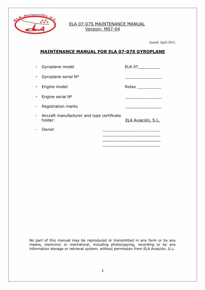
MAINTENANCE MANUAL FOR ELA 07-07S GYROPLANE
- Gyroplane model ELA 07_________
- Gyroplane serial Nº _______________
- Engine model Rotax __________
- Engine serial Nº _______________
- Registration marks _______________
- Aircraft manufacturer and type certificate holder: ELA Aviación, S.L.
- Owner ________________________
______________________
______________________ ______________________
No part of this manual may be reproduced or transmitted in any form or by any
means, electronic or mechanical, including photocopying, recording or by any
information storage or retrieval system, without permission from ELA Aviación, S.L.
ELA 07-07S MAINTENANCE MANUAL
Version: M07-04
Issued: April 2012.
3
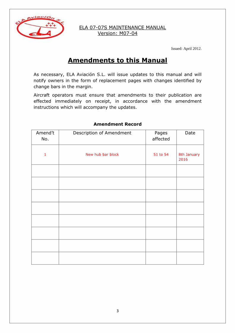
Amendments to this Manual
As necessary, ELA Aviación S.L. will issue updates to this manual and will
notify owners in the form of replacement pages with changes identified by
change bars in the margin.
Aircraft operators must ensure that amendments to their publication are
effected immediately on receipt, in accordance with the amendment
instructions which will accompany the updates.
Amendment Record
Amend’t
No.
Description of Amendment Pages
affected
Date
1
New hub bar block
51 to 54
8th January
2016

ELA 07-07S MAINTENANCE MANUAL
Version: M07-04
Issued: April 2012.
4
Contents
Section I – INTRODUCTION
1.1 General.
1.2 Applicability.
1.3 Terminology.
1.4 Conversion table.
1.5 Periodical maintenance.
1.6 Gyroplane degradation.
1.7 Cleaning.
1.8 Road transport.
1.9 Gyroplane identification.
1.10 Bolts torque.
1.11 Consumables.
Section II – DESCRIPTION OF THE AIRCRAFT
2.1 General.
2.2 Constructional details.
2.3 Overall dimensions.
2.4 Technical data and performances.
2.5 Engine.
2.6 Main parts.
Section III – MAINTENANCE DESCRIPTION
3.1 Maintenance schedule.
3.2 Periodical maintenance.
ELA 07-07S MAINTENANCE MANUAL
Version: M07-04
Issued: April 2012.
5
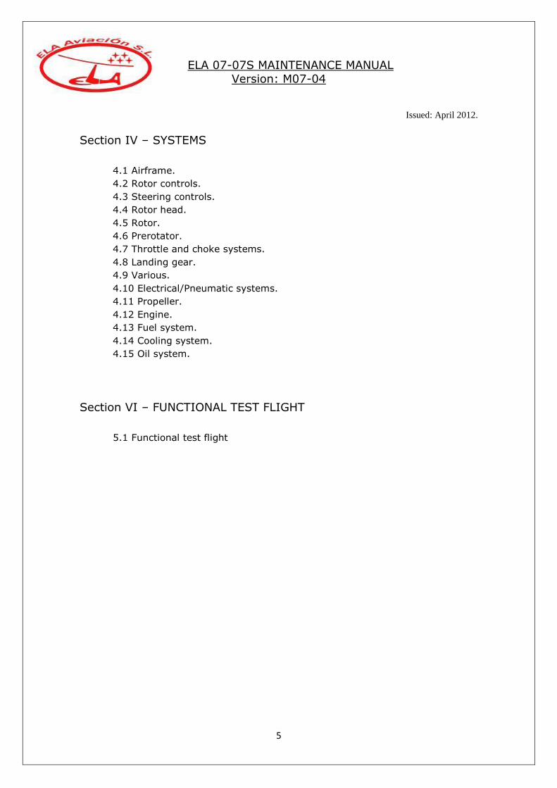
Section IV – SYSTEMS
4.1 Airframe.
4.2 Rotor controls.
4.3 Steering controls.
4.4 Rotor head.
4.5 Rotor.
4.6 Prerotator.
4.7 Throttle and choke systems.
4.8 Landing gear.
4.9 Various.
4.10 Electrical/Pneumatic systems.
4.11 Propeller.
4.12 Engine.
4.13 Fuel system.
4.14 Cooling system.
4.15 Oil system.
Section VI – FUNCTIONAL TEST FLIGHT
5.1 Functional test flight

ELA 07-07S MAINTENANCE MANUAL
Version: M07-04
Issued: April 2012.
6
SECTION I – INTRODUCTION
1.1 GENERAL
This maintenance manual contains the necessary information for safe and
efficient operation of the ELA 07 series of gyroplanes. It explains the
maintenance processes to keep this aircraft airworthy and in good
conditions.
This guide describes the correct maintenance for the parts manufactured by ELA Aviación, S.L. The instructions for the engine maintenance and
servicing are not included in this manual. To carry out engine maintenance appropriately, please refer to the updated engine´s maintenance manual.
Some of the operations described in this manual should be carried out only by approved maintenance ELA staff. See “Maintenance Schedule”.
The owner/operator of this aircraft is the responsible to keep it properly maintained according with the maintenance manuals, provided with this
gyroplane.
Maintenance tasks must be performed by experienced mechanics. Special inspections have to be performed after an operational incident like:
- Hard landing.
- Strikes in flight with birds, trees… - Rotor contact with obstacles. - Lightning strike.
- Rotor over-speed. - Engine failure.
Contact ELA Aviación, S.L. for advice.
ELA 07-07S MAINTENANCE MANUAL
Version: M07-04
Issued: April 2012.
7
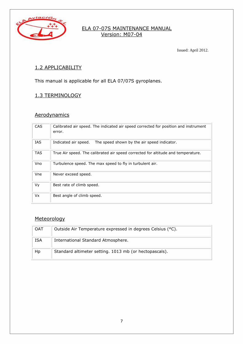
1.2 APPLICABILITY
This manual is applicable for all ELA 07/07S gyroplanes.
1.3 TERMINOLOGY
Aerodynamics
CAS Calibrated air speed. The indicated air speed corrected for position and instrument
error.
IAS Indicated air speed. The speed shown by the air speed indicator.
TAS True Air speed. The calibrated air speed corrected for altitude and temperature.
Vno Turbulence speed. The max speed to fly in turbulent air.
Vne Never exceed speed.
Vy Best rate of climb speed.
Vx Best angle of climb speed.
Meteorology
OAT Outside Air Temperature expressed in degrees Celsius (°C).
ISA International Standard Atmosphere.
Hp Standard altimeter setting. 1013 mb (or hectopascals).

ELA 07-07S MAINTENANCE MANUAL
Version: M07-04
Issued: April 2012.
8
1.4 CONVERSION TABLE
Temperature from Symbol to Symbol Factor
Fahrenheit Fº Celsius Cº 5/9*(F-
32)
Celsius Cº Fahrenheit Fº 9/5*C+32
Weight from to
Kilograms Kg Pounds Lb *2,205
Pounds Lb Kilograms Kg * 0,4536
Speed from to
Metres per
second m/s Feet per minute ft/min * 196,86
Feet per minute ft/min Metres per second m/s * 0,00508
Kilometres per
hour km/h Knots Kts * 0,54
Knots kts Kilometres per
hour Km/h * 1,852
Knots Kts Miles per hour mph * 1,15
Miles per hour mph Knots Kts * 0,87
Pressure from to
Atmospheres Atm Pounds per square
inch psi * 14,8
Pounds per square
inch psi Atmospheres Atm * 0,06756
Distance from to
Kilometres Km Nautical Miles nm * 0,540
Nautical miles nm Kilometres Km. * 1.852
Statute miles sm Nautical Miles nm * 0,87

ELA 07-07S MAINTENANCE MANUAL
Version: M07-04
Issued: April 2012.
9
Nautical Miles nm Statute miles sm * 1,15
Meters m Feet ft * 3.281
Centimetres cm Inches in * 0,3937
Inches in Centimetres cm. * 2.54
Volume from to
Litres lt US Gallons US gal * 0,2642
US Gallons US gal Litres lt * 3.785
Area from to
Square Meters m² Square Feet ft² * 10,76
Square Feet ft² Square Meters m² * 0,0929
1.5 PERIODICAL MAINTENANCE
Certain parts require scheduled maintenance regardless of flying hours. This
maintenance must be carried out in addition to the flight hours related
maintenance.
The relevant maintenance to the 100 hrs should be carried out (as an
annual inspection) in case that the gyroplane has not flown the 100 hrs
within a year.
All rubber parts and hoses should be replaced every 5 years or 500 flight hours, which comes first.
1.6 GYROPLANE DEGRADATION
High humidity, especially in combination with salt-laden atmosphere will
lead to degradation and corrosion of some parts of the gyroplane. Protect the metal parts of the gyroplane such the engine, rotor head, rotor
hub bar, control systems… with WD-40 or ACF-50 oil. Sunlight and heat impact can degrade the composite parts of the gyroplane.
Whenever possible place the gyro in a protected area.
ELA 07-07S MAINTENANCE MANUAL
Version: M07-04
Issued: April 2012.
10
The manufacturer takes no responsibility for damage due to improper
usage.
1.7 CLEANING
It is important to keep the gyroplane and its engine clean to maintain it in
good conditions. When cleaning, some mistakes or damages can be found.
Rotor blades and propeller should be always clean as they are very important to keep the best performances.
In order to protect the gyroplane from dust, humidity, bird soil… is advisable to cover it when parked in the hangar.
Use car soap with water to clean the external parts, windscreen should be cleaned only with polycarbonate soup or polish.
Protect the metal parts of the gyroplane and engine against corrosion, especially in high humidity conditions with “WD-40” or ACF-50 oil.
1.8 ROAD TRANSPORT
Take the rotor blades off and package them carefully as they can be
damaged during transportation by road. Transport the gyro with minimum
fuel for safety.
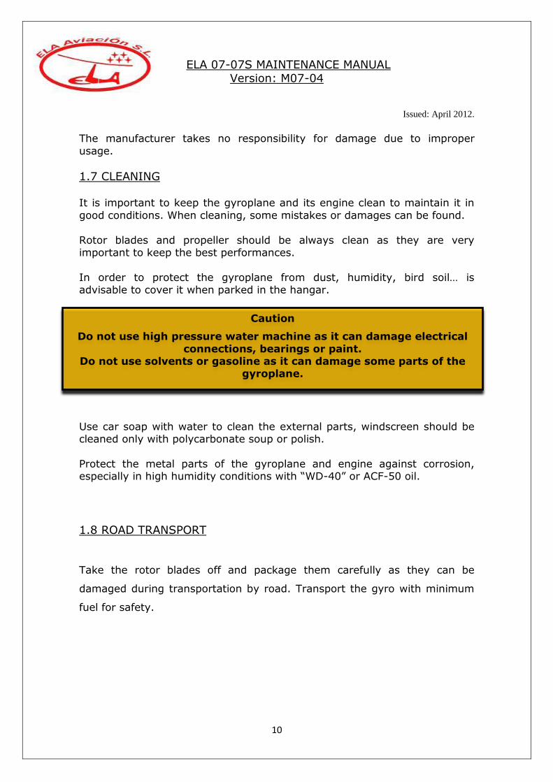
Caution
Do not use high pressure water machine as it can damage electrical
connections, bearings or paint. Do not use solvents or gasoline as it can damage some parts of the
gyroplane.
ELA 07-07S MAINTENANCE MANUAL
Version: M07-04
Issued: April 2012.
11
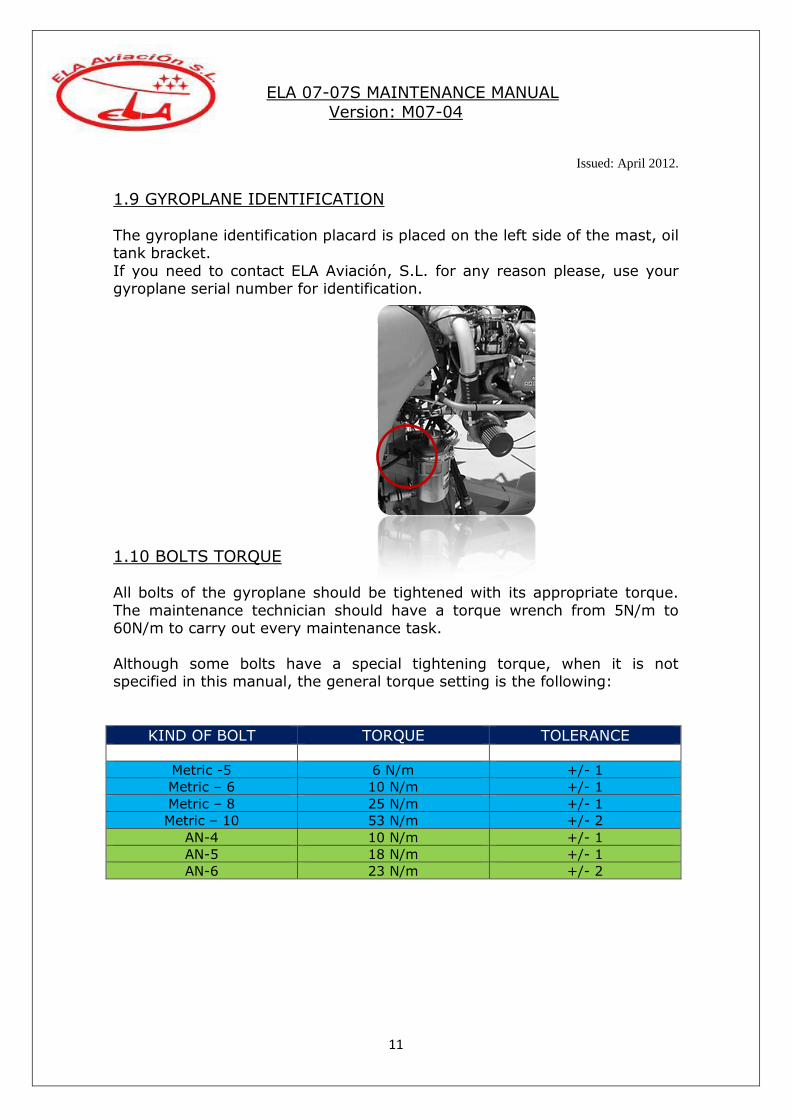
1.9 GYROPLANE IDENTIFICATION
The gyroplane identification placard is placed on the left side of the mast, oil tank bracket.
If you need to contact ELA Aviación, S.L. for any reason please, use your gyroplane serial number for identification.
1.10 BOLTS TORQUE All bolts of the gyroplane should be tightened with its appropriate torque.
The maintenance technician should have a torque wrench from 5N/m to 60N/m to carry out every maintenance task.
Although some bolts have a special tightening torque, when it is not specified in this manual, the general torque setting is the following:
KIND OF BOLT TORQUE TOLERANCE
Metric -5 6 N/m +/- 1
Metric – 6 10 N/m +/- 1
Metric – 8 25 N/m +/- 1
Metric – 10 53 N/m +/- 2
AN-4 10 N/m +/- 1
AN-5 18 N/m +/- 1
AN-6 23 N/m +/- 2

ELA 07-07S MAINTENANCE MANUAL
Version: M07-04
Issued: April 2012.
12
1.11 CONSUMABLES Consumables used to perform the maintenance or assembly parts in the gyroplane:
- Lubricants:
- Oil WD-40. - Spray grease Krafft. - Grease Molykote BR2 Plus.
- Grease “water repellent” Brugarolas JET-70. - Oil ACF-50.
- Valvoline sae-90.
- Threadlockers: - Loctite 243.
- Loctite 270. - Loctite 641.
- Loctite 638. - Engine oil: (see latest issue of engine maintenance manual)
- Coolant: 50/50 Antifreeze with water (see latest issue of engine
maintenance manual). - “Meguiar´s Mirror Glaze” for the windscreens.

ELA 07-07S MAINTENANCE MANUAL
Version: M07-04
Issued: April 2012.
13
Section II – DESCRIPTION OF THE AIRCRAFT
2.1 GENERAL
The ELA 07 gyroplane is designed as a 2-seater, tandem-configured three-
axis aircraft with dual controls and single engine, ideal for flight instruction
purposes. In addition to flight training and general recreational flying, the
flight characteristics of this gyroplane make such aircraft ideally suited for
tasks such as air transportation, forestry, border, livestock and traffic
surveillance, electrical pylon inspection, aerial still and film photography,
fumigation, crop spray etc. These are typically the kind of activities which
benefit from the very low speeds at which this gyroplane can operate as
well as its characteristic zero downwash. The manoeuvring capability of the
aircraft in all configurations is exceptionally high, and since it is impossible
for the machine to enter into a stall or a spin, it has an unequalled flight
safety record. Its characteristic short take-off and landing runs make it
particularly suitable for operation from fields of modest dimension.
2.2 CONSTRUCTIONAL DETAILS
The Airframe is one single part built from stainless steel TIG (tungsten-
inert-gas) welded to guarantee lifetime freedom from corrosion. The
gyroplane is a tricycle landing gear with front wheel.
The cockpit is made from composite materials, ensuring high strength with
low weight. The high sided open cockpits have clear polycarbonate
windshields to protect the occupants from wind effects but offer excellent
all-round visibility.
The layout of the instrument panel house switches which fall easily to
hand around the desired set of instruments.
The rotor blades are made from aluminium and composite materials.
The power unit consists of a pusher piston engine and three bladed
composite propeller.
The tail planes are made from composite materials and consist of a fix
horizontal stabilizer with winglets at the ends and a vertical surface in the
centre subdivided in a fix fin and rudder.
ELA 07-07S MAINTENANCE MANUAL
Version: M07-04
Issued: April 2012.
14
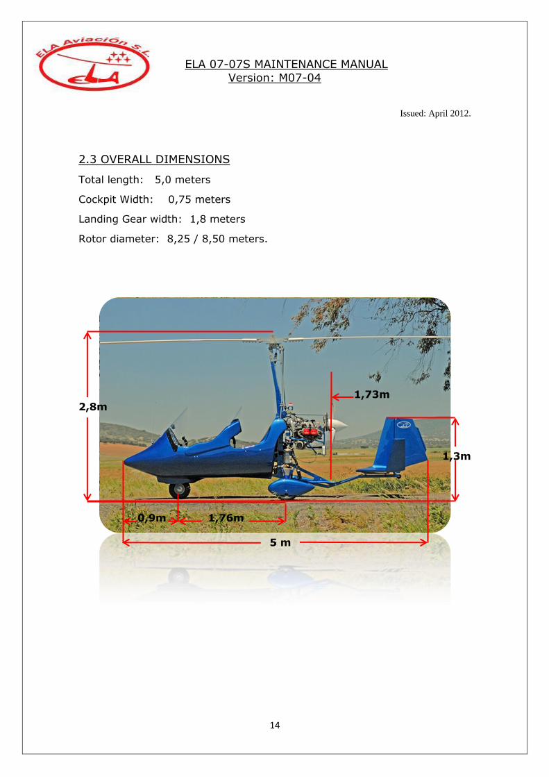
2.3 OVERALL DIMENSIONS
Total length: 5,0 meters
Cockpit Width: 0,75 meters
Landing Gear width: 1,8 meters
Rotor diameter: 8,25 / 8,50 meters.
1,73m 2,8m
1,3m
0,9m 1,76m 5 m

ELA 07-07S MAINTENANCE MANUAL
Version: M07-04
Issued: April 2012.
15
2.4 TECHNICAL DATA AND PERFORMANCES
The following performance parameters were determined by flight testing with average piloting skills, aircraft with 450 kg MTOW, in good conditions
and clean rotor blades and propeller. The parameters apply to standard conditions ISA (15ºC temperature, sea level and standard pressure).
Gyroplane data With Rotax 912 ULS (100 HP) With Rotax 914 TURBO (115
HP)
Empty weight (standard equipment) 258 kg 264 kg
MTOW 450 kg 450 kg
Useful load (standard equipment) 192 kg 186 kg
Vne 100 mph 100 mph
Cruise speed 60 – 85 mph 60 – 90 mph
Min speed (level flight/full power)) 25 mph 20 mph
Rate of climb 650 ft/min 1000 ft/min
Take-off distance 100 m 70 m
Landing distance 0 – 30 m 0 – 30 m
Fuel Gasoline
Fuel capacity 75 l
Unusable fuel 3 l
Fuel consumption 15 – 20 l/h
2.5 ENGINE
- Manufacturer ……………………………………………………………………………… Rotax
- Take-off power: o 912 ULS……………………………………………………………….………… 100 hp o 914 UL………………………………………………………………………….. 115 hp - Max. engine speed……………….……………………………….…………… 5800 rpm
- Cooling system………………………………………………………………………. Air/liquid

ELA 07-07S MAINTENANCE MANUAL
Version: M07-04
Issued: April 2012.
16
- Coolant………………………………………………………………. 50% water/antifreeze - Electric installation…………………………………………………………………………. 12v
2.6 MAIN PARTS
1
2
3 4
12 11 13
9
5 6
10 7
8
Parts:
1 – Rotor blades.
2 – Hub bar.
3 – Rotor head.
4 – Mast.
5 – Rear keel.
6 – Landing gear.
7 – Main wheels.
8 – Front wheel.
9 – Cockpit.
10 – Landing light.
11 – Windscreens.
12 – Engine.
13 – Tail planes.
ELA 07-07S MAINTENANCE MANUAL
Version: M07-04
Issued: April 2012.
17
8 1
4 5
2 3 6 7
Parts:
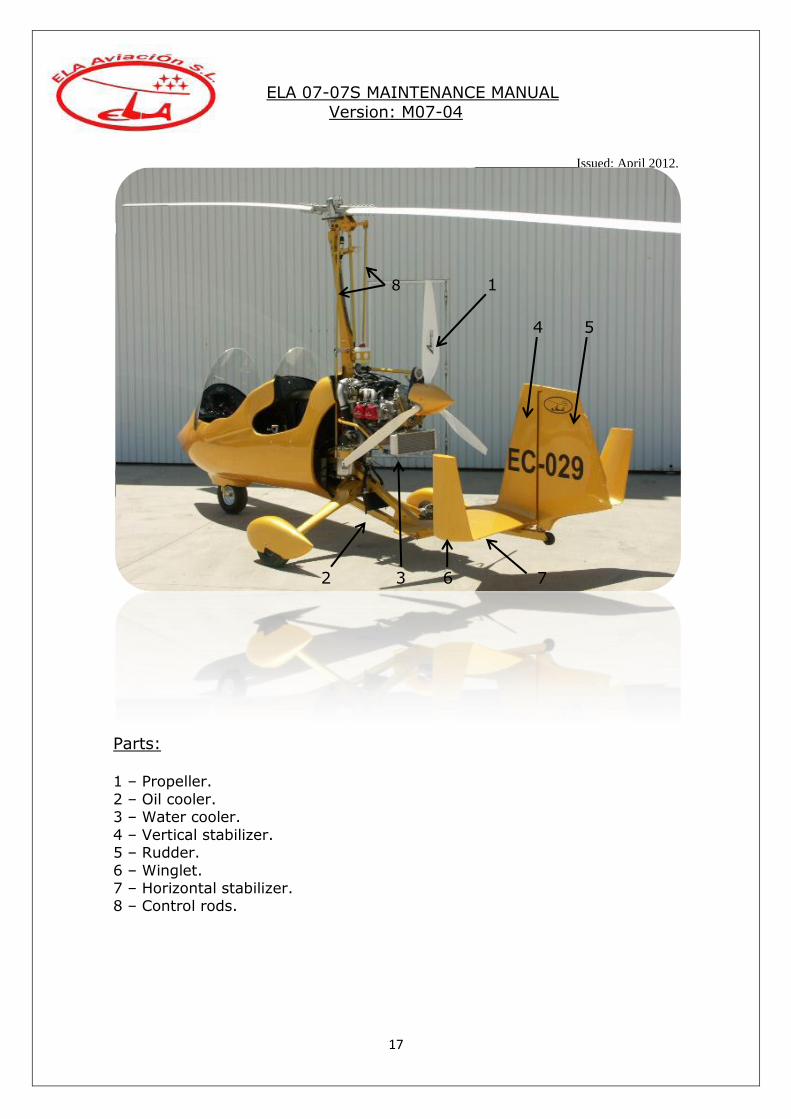
1 – Propeller.
2 – Oil cooler. 3 – Water cooler.
4 – Vertical stabilizer. 5 – Rudder.
6 – Winglet. 7 – Horizontal stabilizer. 8 – Control rods.

ELA 07-07S MAINTENANCE MANUAL
Version: M07-04
Issued: April 2012.
18
2 3 1 4
5
6
7
Parts:
1 – Engine.
2 – Water tank. 3 – Horizontal prerotator transmission. 4 – Prerotator system.
5 – Carburettor. 6 – Oil tank.
7 – Air filter (914).
ELA 07-07S MAINTENANCE MANUAL
Version: M07-04
Issued: April 2012.
19
5
1
2
3
4
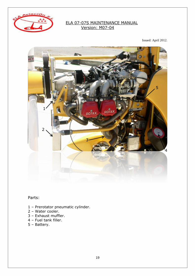
Parts: 1 – Prerotator pneumatic cylinder. 2 – Water cooler.
3 – Exhaust muffler. 4 – Fuel tank filler.
5 – Battery.
ELA 07-07S MAINTENANCE MANUAL
Version: M07-04
Issued: April 2012.
20
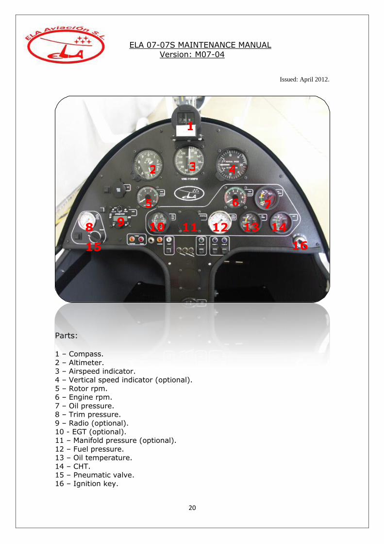
Parts:
1 – Compass.
2 – Altimeter. 3 – Airspeed indicator. 4 – Vertical speed indicator (optional).
5 – Rotor rpm. 6 – Engine rpm.
7 – Oil pressure. 8 – Trim pressure.
9 – Radio (optional). 10 - EGT (optional). 11 – Manifold pressure (optional).
12 – Fuel pressure. 13 – Oil temperature.
14 – CHT. 15 – Pneumatic valve. 16 – Ignition key.
1
2 3 4
5 6 7
8 9
15
10 11 12 13 14
16
ELA 07-07S MAINTENANCE MANUAL
Version: M07-04
Issued: April 2012.
21
1 2 3 4 5 6 7
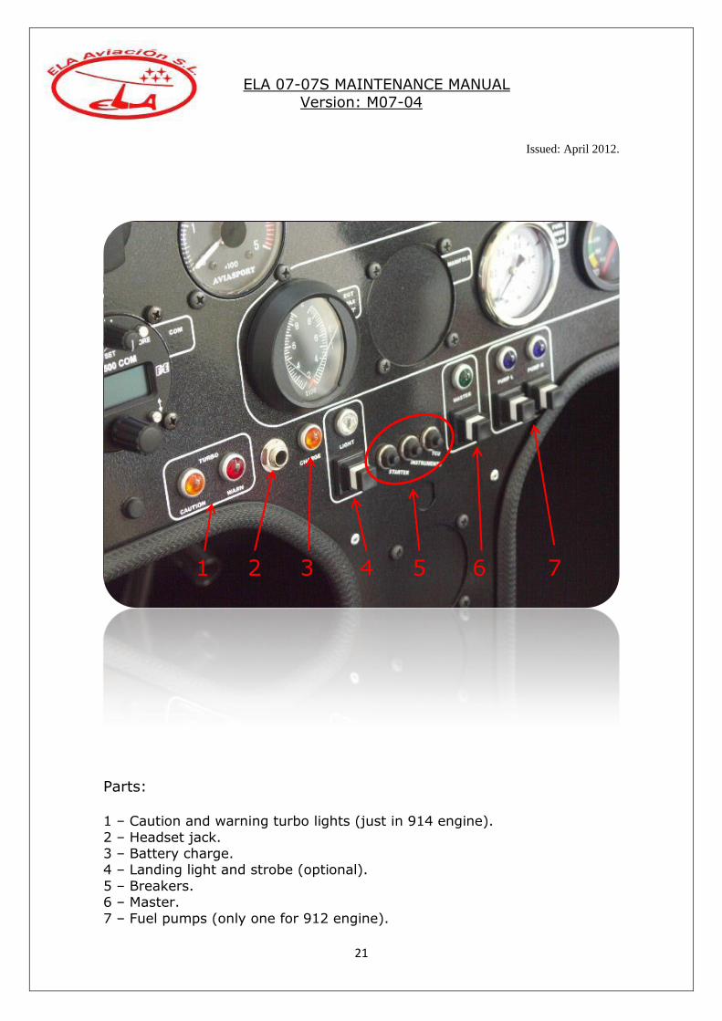
Parts:
1 – Caution and warning turbo lights (just in 914 engine).
2 – Headset jack. 3 – Battery charge. 4 – Landing light and strobe (optional).
5 – Breakers. 6 – Master.
7 – Fuel pumps (only one for 912 engine).

ELA 07-07S MAINTENANCE MANUAL
Version: M07-04
Issued: April 2012.
22
Front/Rear Stick Front pedals
Trim
Prerotator
PTT Radio
Throttle, brake and roll trim
Throttle
Wheel brake
Roll trim
ELA 07-07S MAINTENANCE MANUAL
Version: M07-04
Issued: April 2012.
23
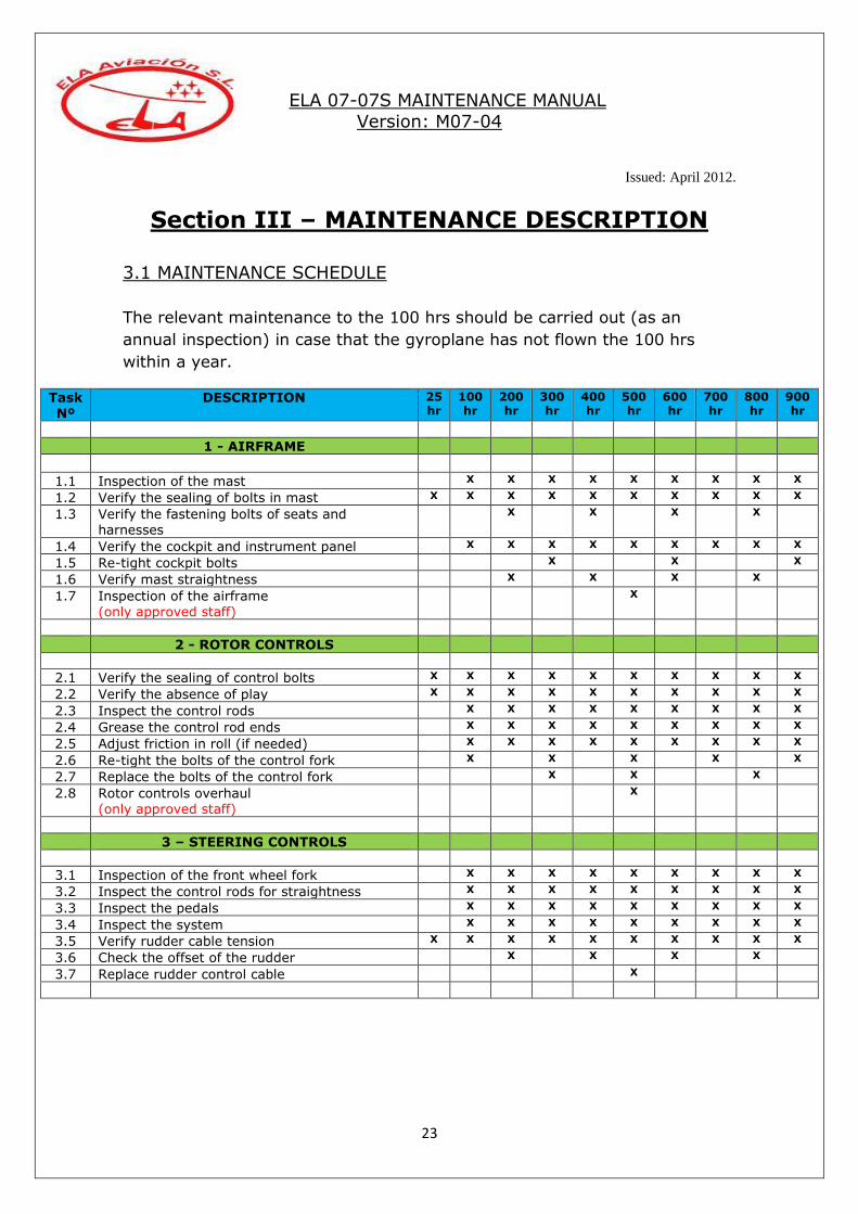
Section III – MAINTENANCE DESCRIPTION
3.1 MAINTENANCE SCHEDULE
The relevant maintenance to the 100 hrs should be carried out (as an
annual inspection) in case that the gyroplane has not flown the 100 hrs
within a year.
Task Nº
DESCRIPTION 25 hr
100 hr
200 hr
300 hr
400 hr
500 hr
600 hr
700 hr
800 hr
900 hr
1 - AIRFRAME
1.1 Inspection of the mast X X X X X X X X X
1.2 Verify the sealing of bolts in mast X X X X X X X X X X
1.3 Verify the fastening bolts of seats and harnesses
X X X X
1.4 Verify the cockpit and instrument panel X X X X X X X X X
1.5 Re-tight cockpit bolts X X X
1.6 Verify mast straightness X X X X
1.7 Inspection of the airframe (only approved staff)
X
2 - ROTOR CONTROLS
2.1 Verify the sealing of control bolts X X X X X X X X X X
2.2 Verify the absence of play X X X X X X X X X X
2.3 Inspect the control rods X X X X X X X X X
2.4 Grease the control rod ends X X X X X X X X X
2.5 Adjust friction in roll (if needed) X X X X X X X X X
2.6 Re-tight the bolts of the control fork X X X X X
2.7 Replace the bolts of the control fork X X X
2.8 Rotor controls overhaul (only approved staff)
X
3 – STEERING CONTROLS
3.1 Inspection of the front wheel fork X X X X X X X X X
3.2 Inspect the control rods for straightness X X X X X X X X X
3.3 Inspect the pedals X X X X X X X X X
3.4 Inspect the system X X X X X X X X X
3.5 Verify rudder cable tension X X X X X X X X X X
3.6 Check the offset of the rudder X X X X
3.7 Replace rudder control cable X
ELA 07-07S MAINTENANCE MANUAL
Version: M07-04
Issued: April 2012.
24
Task
Nº
DESCRIPTION 25 hr
100 hr
200 hr
300 hr
400 hr
500 hr
600 hr
700 hr
800 hr
900 hr
4 – ROTOR HEAD
4.1 Verify the sealing of bolts X X X X X X X X X X
4.2 Inspect the rotor head X X X X X X X X X
4.3 Adjust lightening of roll and pitch pivot bolts X X X X
4.4 Grease the roll and pitch pivots X X X X
4.5 Inspect the prerotator ring gear and bendix
pinion
X X X X X X X X X
4.6 Grease the prerotator X X X X X X X X X
4.7 Grease the top bearing of bendix (see version) X X X X X X X X X
4.8 Inspect the rotor brake´s pad X X X X
4.9 Clean/degrease the portion part of the rotor brake
X X X X X X X X X
4.10 Replace rotor head bolts X
4.11 Inspect teeter towers
(only approved staff)
X
5 – ROTOR BLADES
5.1 Inspect the rotor X X X X X X X X X
5.2 Verify tightening of teeter bolt X X X X
5.3 Perform general inspection of rotor (only approved staff)
X
6 – PREROTATOR
6.1 Verify sealing of bolts X X X X X X X X X X
6.2 Inspect prerotator X X X X X X X X X
6.3 Replace the belt X X X
6.4 Adjust prerotator cable (if fitted) X X X X X X X X X
6.5 Adjust the prerotator rubber pulley X X X X X X X X X
6.6 Inspect the universal joints for play X X X X X X X X X
6.7 Inspect the O-rings X X X X X X X X X
6.8 Grease the bearing of the tensioner X X X X X X X X X
6.9 Grease the rod end bearing of the piston X X X X X X X X X
6.10 Clean and re-grease the universal joints X X X
6.11 Inspect the prerotator axle box X X X X X X X X X
6.12 Replace the bearing of the tensioner X
6.13 Replace the prerotator cable Bowden X
7 – THROTTLE AND CHOKE SYSTEMS
7.1 Inspect the system for smooth operation X X X X X X X X X X
7.2 Inspect the levers for damage X X X X X X X X X X
7.3 Adjust levers friction X X X X X X X X X X
7.4 Inspect the choke system x x x x x x x x x x
7.5 Inspect the locking wires x x x x x x x x x x
7.6 Adjust carburettor synchronization x x x x
7.7 Replace carburettors cable Bowden X

ELA 07-07S MAINTENANCE MANUAL
Version: M07-04
Issued: April 2012.
25
.Task
Nº DESCRIPTION 25
hr 100 hr
200 hr
300 hr
400 hr
500 hr
600 hr
700 hr
800 hr
900 hr
8 – LANDING GEAR
8.1 Tires X X X X X X X X X X
8.2 Verify sealing of landing gear bolts x x x x x x x x x x
8.3 Re-tight landing gear bolts x x x x x
8.4 Inspect landing gear X X X X X X X X X X
8.5 Brake pads X X X X X X X X X
8.6 Clean and re-grease bearings X X X
9 - VARIOUS
9.1 Inspect tail planes X X X X X X X X X X
9.2 Re-tight tail planes attachment bolts X X X
9.3 Replace tail planes bolts X
9.4 Verify conditions of windscreens X X X X X X X X X
9.5 Verify placards X X X X X X X X X
10 – ELECTRICAL/PNEUMATIC SYSTEM
10.1 Inspect the harnesses x X x x X
10.2 Check the battery level X X X X
10.3 Instrument panel X
10.4 Oil the compressor x x X x x X x x X
11 - PROPELLER
11.1 Inspection of the propeller X X X X X X X X X X
11.2 Re-tight the propeller bolts X X X X
11.3 Propeller pitch X X X X
11.3 Replace the propeller bolts X
11.4 Overhaul X X
12 – ENGINE (see engine´s maintenance manual)
12.1 Verify the sealing of engine bolts X X X X X X X X X X
12.2 Replace the engine silent-blocks
(only approved staff)
X
12.3 Replace engine attachment bolts (only approved staff)
X
12.4 Inspect the locking wire for the air filters X X X X X X X X X X
12.5 Inspect the exhaust X X X X X X X X X
13 – FUEL SYSTEM
13.1 Clean the gascolator X X X X X X X X X
13.2 Replace fuel filter X X X X X X X X X
13.3 Clean the filters of the 914 fuel pumps X X X
13.4 Inspect hoses X X X X X X X X X
13.5 Replace the fuel hoses X

ELA 07-07S MAINTENANCE MANUAL
Version: M07-04
Issued: April 2012.
26
3.2 PERIODICAL MAINTENANCE Certain parts require scheduled maintenance regardless of flying hours. This
maintenance must be carried out in addition to the flight hours related
maintenance.
If the gyroplane does not fly for a total time of 100 hrs within a year, the
100hrs maintenance program should be carried out as an annual inspection.
All rubber parts and hoses should be replaced every 5 years independently
of the flight hours. Remove the bolts of the rotor controls rotor head and rotor blades/hub bar
every two years and confirm the absence of corrosion or wear. Apply WD-40 or ACF-50 oil to the unthreaded part of the bolt and install it with a new
stop nut. If corrosion or wear is found replace the bolt immediately.
13.6 Perform the fuel tank test X X X X
Task Nº
DESCRIPTION 25 hr
100 hr
200 hr
300 hr
400 hr
500 hr
600 hr
700 hr
800 hr
900 hr
14 – COOLING SYSTEM
14.1 Inspection of the system X X X X X X X X X X
14.2 Replace the silent-blocks X X X x
14.3 Replace hoses and coolant X
15 – OIL SYSTEM
15.1 Inspection of the system X X X X X X X X X X
15.2 Replace the hoses and clamps X
ELA 07-07S MAINTENANCE MANUAL
Version: M07-04
Issued: April 2012.
27
Section IV – SYSTEMS
4.1 AIRFRAME The main airframe of the gyroplane is constructed from stainless steel, TIG
welded. The airframe is one single unit which don´t have replaceable parts. Any repair or modification to the airframe by third persons are not allowed
or approved.
1.1 Inspection of the mast
Inspect the mast and its welds to
confirm the absence of cracks in the engine brackets.
Inspect the welds of the bracket for the 90º prerotator box.
Inspect the battery´s bracket.
ELA 07-07S MAINTENANCE MANUAL
Version: M07-04
Issued: April 2012.
28
Inspect the oil tank bracket and the mast reinforcements.
Inspect the mast and welds at the bottom part.

ELA 07-07S MAINTENANCE MANUAL
Version: M07-04
Issued: April 2012.
29
1.2 Verify the sealing of bolts in mast
Verify that the red marks are aligned between nut and bolt in:
- Rear four point harness (if fitted)
- 90º Prerotator box. - Battery bracket.
- Engine brackets.
- Starter relay.
- Regulator.

ELA 07-07S MAINTENANCE MANUAL
Version: M07-04
Issued: April 2012.
30
1.4 Verify cockpit and instrument panel
Verify that the cockpit and instrument panel are secured.
1.3 Verify the fastening bolts of seats and harnesses
- Re-tight the four M-6 attachment bolts for each seat.
- Re-tight the bolts for the harnesses.
1.5 Re-tight cockpit bolts
Note
The M-10 bolts for the harness in the rear seat should be tightened to 25 N/m.

ELA 07-07S MAINTENANCE MANUAL
Version: M07-04
Issued: April 2012.
31
Re-tight the cockpit bolts.
M-4 bolts gently tightened by hand.
ELA 07-07S MAINTENANCE MANUAL
Version: M07-04
Issued: April 2012.
32
1.7 Inspection of the airframe (only approved staff)
Inspection of all welds for possible cracks in the airframe.
1.6 Verify mast straightness
Remove the instrument panel and measure the distance between the mast
and the keel. The measurement should be between 2595 and 2615mm.
ELA 07-07S MAINTENANCE MANUAL
Version: M07-04
Issued: April 2012.
33
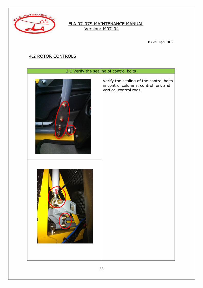
4.2 ROTOR CONTROLS
2.1 Verify the sealing of control bolts
Verify the sealing of the control bolts in control columns, control fork and vertical control rods.

ELA 07-07S MAINTENANCE MANUAL
Version: M07-04
Issued: April 2012.
34
2.1 Verify the sealing of control bolts
ELA 07-07S MAINTENANCE MANUAL
Version: M07-04
Issued: April 2012.
35
2.5 Adjust the friction in roll (if needed)
Some friction in the roll axis of the rotor controls is more comfortable to
avoid resonant vibration in flight. Slightly tight the bolts of the plastic bracket.
Test in ground the amount of friction, it should be a compromise
between handle and friction.
2.2 Verify the absence of play
With the rotor brake ON”, hold the front stick and make some pressure fore and aft to check if there is play in the whole control system. Some
millimetres of play at the top of the stick are allowed, 8 mm or more are not acceptable.
2.3 Inspect the control rods
Visually inspect the vertical control rods for wear or cracks.
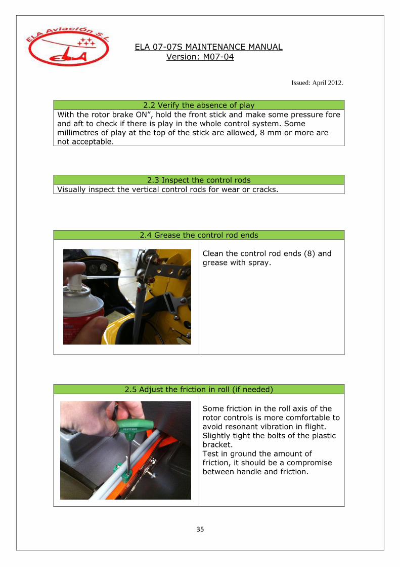
2.4 Grease the control rod ends
Clean the control rod ends (8) and
grease with spray.
ELA 07-07S MAINTENANCE MANUAL
Version: M07-04
Issued: April 2012.
36
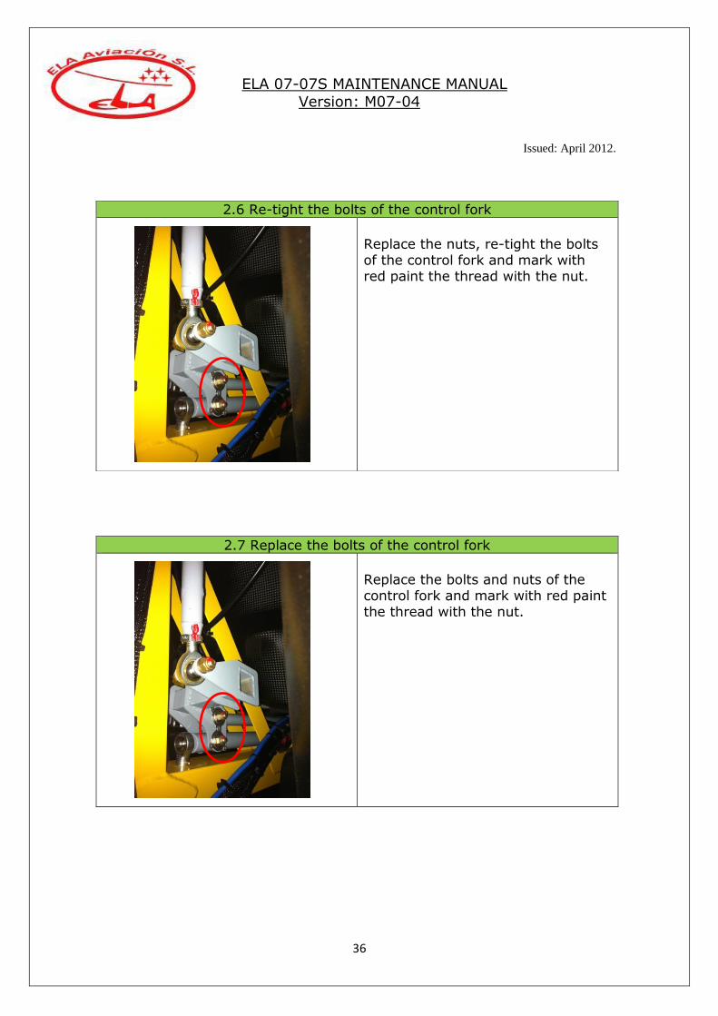
2.6 Re-tight the bolts of the control fork
Replace the nuts, re-tight the bolts of the control fork and mark with red paint the thread with the nut.
2.7 Replace the bolts of the control fork
Replace the bolts and nuts of the control fork and mark with red paint the thread with the nut.

ELA 07-07S MAINTENANCE MANUAL
Version: M07-04
Issued: April 2012.
37
2.8 Rotor controls overhaul (only approved staff)
Disassembly the whole rotor system
from the gyroplane. Inspect every control rod (2
horizontal and 4 vertical) for straightness, cracks or damage.
Inspect the control fork for cracks or
damage.
Replace the bearings of the control columns (8).
Replace the bearings of the control fork.

ELA 07-07S MAINTENANCE MANUAL
Version: M07-04
Issued: April 2012.
38
Replace the rod end bearings of the vertical rods (8).
Assembly the new rod end bearings
with the following measurements between centres:
Upper rods:
- Right: 900mm. - Left: 882mm.
Lower rods:
Right and left: 770mm. Grease the rod ends.
Replace all bolts and nuts of the
control system, 10 for the horizontal rods and 10 for the vertical rods.
ELA 07-07S MAINTENANCE MANUAL
Version: M07-04
Issued: April 2012.
39
4.3 STEERING CONTROLS
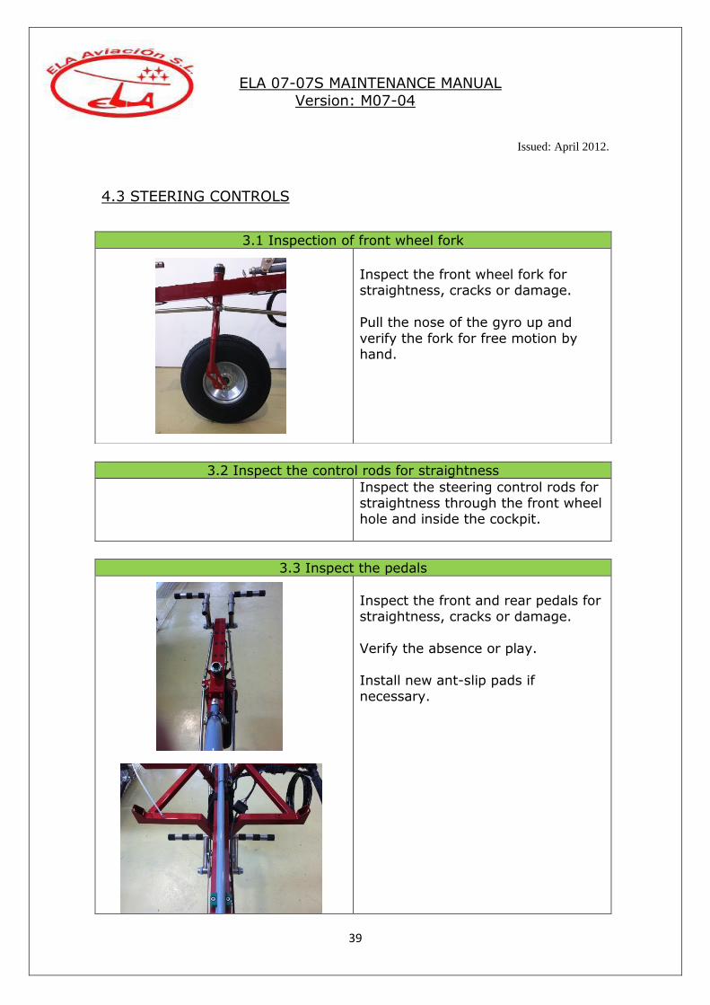
3.2 Inspect the control rods for straightness
Inspect the steering control rods for straightness through the front wheel hole and inside the cockpit.
3.3 Inspect the pedals
Inspect the front and rear pedals for straightness, cracks or damage.
Verify the absence or play.
Install new ant-slip pads if necessary.
3.1 Inspection of front wheel fork
Inspect the front wheel fork for straightness, cracks or damage.
Pull the nose of the gyro up and
verify the fork for free motion by hand.

ELA 07-07S MAINTENANCE MANUAL
Version: M07-04
Issued: April 2012.
40
3.4 Inspect the system
Inspect the entire rudder cable for wear or damage.
Inspect the rudder cable pulleys for free motion. Inspect the conditions of the cable retainers of the rudder.
3.5 Verify rudder cable tension
Verify rudder cable tension. With the front wheel straight, the tension
should be between 45 and 55 pounds.
It is important that the tension of
this cable is within limits to avoid a probably rudder flutter at high speeds.
Adjust the tension tightening the turnbuckle near the rear/right pedal. Secure it again with safety wire.
After adjusting the cable check the offset of the rudder (see point 3.6)

ELA 07-07S MAINTENANCE MANUAL
Version: M07-04
Issued: April 2012.
41
3.6 Check the offset of the rudder
The rudder should be mounted
offset respect to the front wheel. Ensure the front wheel of the gyro is
straight and measure the distance between the trailing edge at the top of the rudder and the trailing edge
of the top of the right winglet. It should be 90cm +/- 1.
3.7 Replace rudder control cable.
Replace the rudder cable and turnbuckle.

ELA 07-07S MAINTENANCE MANUAL
Version: M07-04
Issued: April 2012.
42
4.4 ROTOR HEAD
4.1 Verify the sealing of bolts
Verify the sealing of the bolts of the
rotor head.
4.2 Inspect the rotor head
Inspect the rotor head for cracks.
Inspect the rotor head for
deformities or twisting using a rule.

ELA 07-07S MAINTENANCE MANUAL
Version: M07-04
Issued: April 2012.
43
4.3 Adjust tightening of roll and pitch pivot bolts
Adjust the tightening of roll and pitch bolts.
Tight them up to 20N/m and slacken about ¼ of turn, or the necessary to
operate the controls easily. Put a new safety pin.
4.4 Grease the roll and pitch pivots
Grease with Molycote (pag 29) the rotor head pivots. Push the greaser
until see the grease coming out.
4.5 Inspect prerotator ring gear and bendix pinion
Inspect the prerotator´s ring gear
and bendix pinion for wear or damage.

ELA 07-07S MAINTENANCE MANUAL
Version: M07-04
Issued: April 2012.
44
4.6 Grease the prerotator
Grease the prerotator ring gear with
“Brugarolas JET70” (pag 9).
Engage the bendix with the ring
gear and grease the interior body of the bendix with WD-40 spray (pag
9).
4.7 Grease top bearing of the bendix (see version)
Grease the needle bearing at the top
of the bendix with spray grease.
See version, new versions don´t need maintenance.
4.8 Inspect the rotor brake´s pad

ELA 07-07S MAINTENANCE MANUAL
Version: M07-04
Issued: April 2012.
45
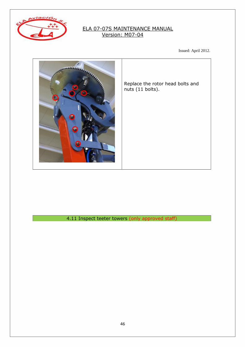
4.10 Replace rotor head bolts
Inspect the brake´s pad for excessive wear or damage.
4.9 Clean/de-grease the portion part for the rotor brake.
Clean/degrease the portion part for
the rotor brake.
ELA 07-07S MAINTENANCE MANUAL
Version: M07-04
Issued: April 2012.
46
Replace the rotor head bolts and nuts (11 bolts).
4.11 Inspect teeter towers (only approved staff)

ELA 07-07S MAINTENANCE MANUAL
Version: M07-04
Issued: April 2012.
47
Disassembly the teeter towers, clean the interior´s hole of the main gear axle and inspect it carefully for
cracks, use a lantern. Oil it with WD-40 to prevent for rusting.
Clean and inspect carefully the
teeter towers for cracks or damage.

ELA 07-07S MAINTENANCE MANUAL
Version: M07-04
Issued: April 2012.
48
4.5 ROTOR
5.1 Inspect the rotor
Visually inspect the rotor blades for cracks, wear, deformities…
Visually inspect the hub bar for cracks, wear, deformities…
5.2 Verify tightening of teeter bolt
Old system:
Tight the nut to 20N/m and slacken about ¼ turn. Put safety pin.
New system:
That bolt should be tightened strong “BY HAND”. Then tighten the allen
bolt and put the safety pin.
A lower or higher torque will create
rotor vibrations.
ELA 07-07S MAINTENANCE MANUAL
Version: M07-04
Issued: April 2012.
49
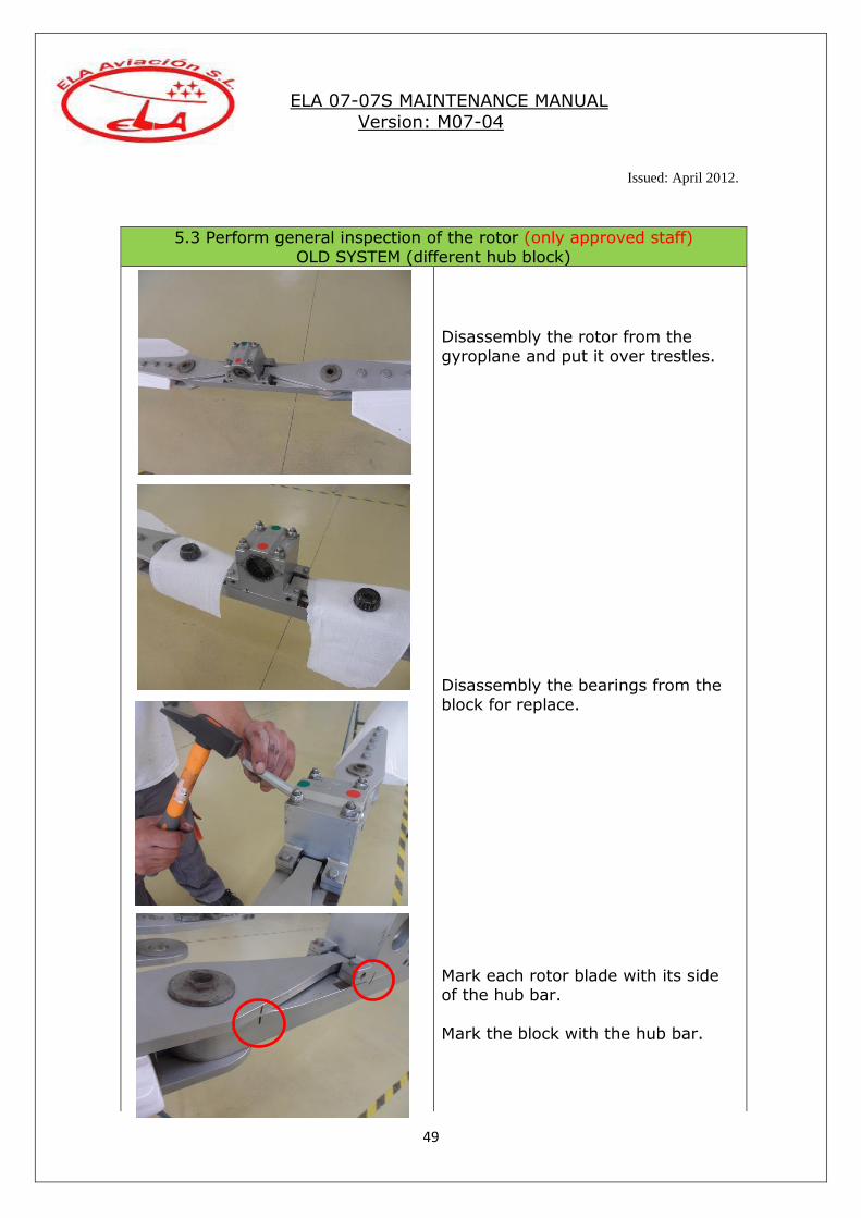
5.3 Perform general inspection of the rotor (only approved staff)
OLD SYSTEM (different hub block)
Disassembly the rotor from the
gyroplane and put it over trestles.
Disassembly the bearings from the block for replace.
Mark each rotor blade with its side of the hub bar.
Mark the block with the hub bar.

ELA 07-07S MAINTENANCE MANUAL
Version: M07-04
Issued: April 2012.
50
Remove the rotor blades from the hub bar.
Clean the bolts of the rotor blades and grease with spray.
Disassembly the block from the hub bar for cleaning.
Inspect carefully the block for
possible cracks or damage. Remove the bolts and bushes from
the hub bar and inspect it for possible cracks or damage.
Remove the bolts and bushes that hold the block. Clean and inspect the holes for
cracks. Install new bushings greased with
spray.

ELA 07-07S MAINTENANCE MANUAL
Version: M07-04
Issued: April 2012.
51
Remove the plates from the rotor
blades and inspect the holes for possible cracks or defects.
Inspect the plates of the rotor blades.
Re-assembly the plates with new bolts and nuts.
Install the new bearings in the block
and assembly the block in the hub bar.
Assembly the blades with the hub bar using new “safety washers” and
nuts.
Install the rotor in the gyroplane using a new teeter bolt.

ELA 07-07S MAINTENANCE MANUAL
Version: M07-04
Issued: April 2012.
52
5.3 Perform general inspection of the rotor (only by approved staff) NEW SYSTEM (different hub block)
Disassembly the rotor from the gyroplane and put it over
trestles.
Slack the retainers of the
threaded hub.
ELA 07-07S MAINTENANCE MANUAL
Version: M07-04
Issued: April 2012.
53
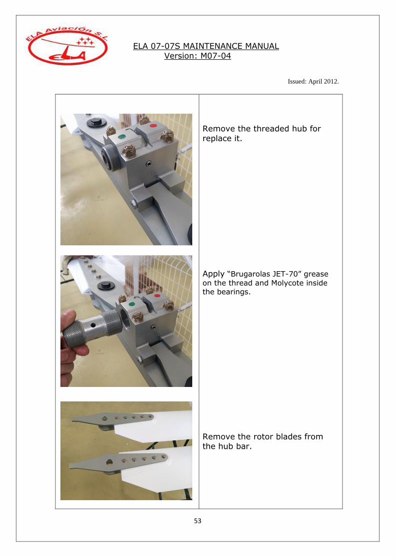
Remove the threaded hub for
replace it.
Apply “Brugarolas JET-70” grease
on the thread and Molycote inside the bearings.
Remove the rotor blades from the hub bar.
ELA 07-07S MAINTENANCE MANUAL
Version: M07-04
Issued: April 2012.
54
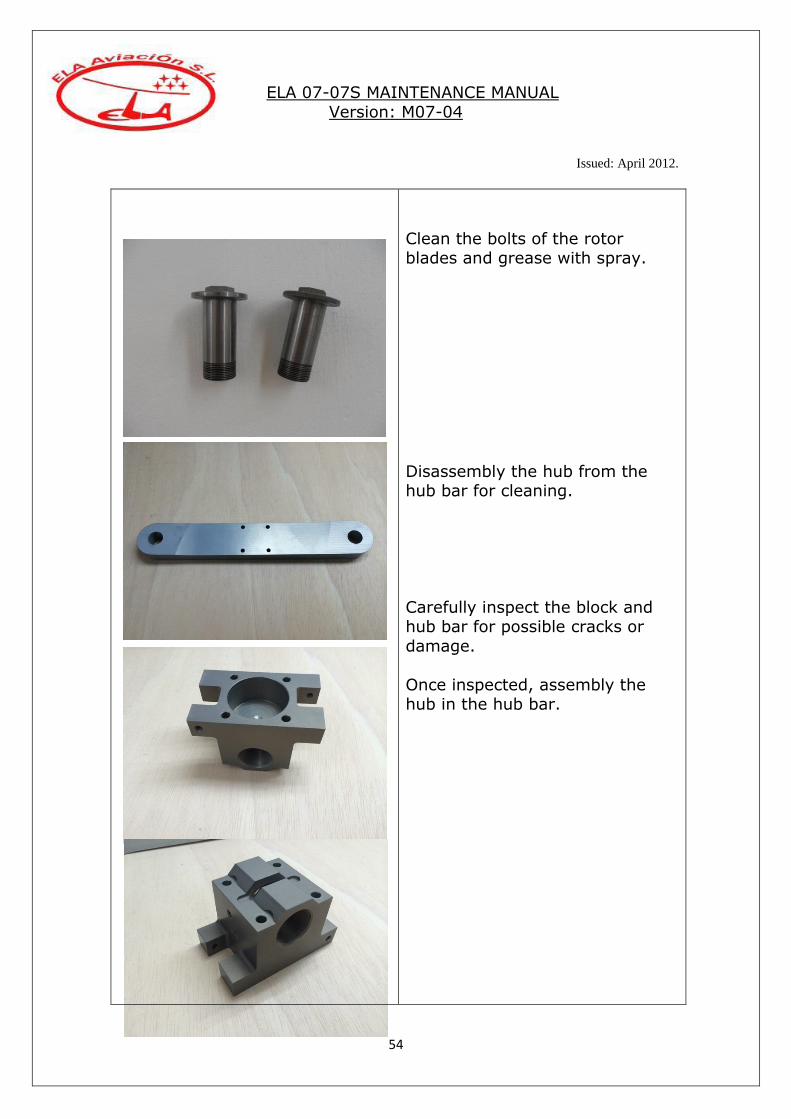
Clean the bolts of the rotor blades and grease with spray.
Disassembly the hub from the hub bar for cleaning.
Carefully inspect the block and hub bar for possible cracks or
damage.
Once inspected, assembly the hub in the hub bar.

ELA 07-07S MAINTENANCE MANUAL
Version: M07-04
Issued: April 2012.
55
Remove the plates from the rotor
blades and inspect the holes for possible cracks or defects.
Inspect the plates of the rotor
blades.
Re-assembly the plates with new bolts and nuts.
Assembly the blades with the hub bar using new “safety washers”
and nuts.
Take into account the correct position of each part.
Install the rotor in the gyroplane using a new teeter bolt.
ELA 07-07S MAINTENANCE MANUAL
Version: M07-04
Issued: April 2012.
56
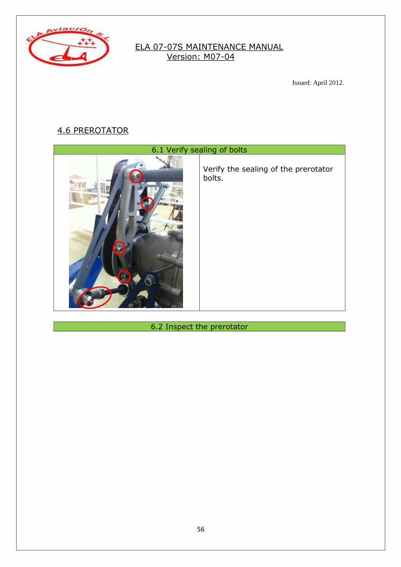
4.6 PREROTATOR
6.1 Verify sealing of bolts
Verify the sealing of the prerotator bolts.
6.2 Inspect the prerotator

ELA 07-07S MAINTENANCE MANUAL
Version: M07-04
Issued: April 2012.
57
6.4 Adjust the prerotator cable (if fitted)
Inspect the prerotator tensioner and bracket for cracks or damage.
Inspect the belt for damage or deformities.
Inspect the horizontal and vertical shafts for cracks or deformities.
6.3 Replace the belt
Remove the propeller and replace the belt. Install new bolts (6) in the propeller.
ELA 07-07S MAINTENANCE MANUAL
Version: M07-04
Issued: April 2012.
58
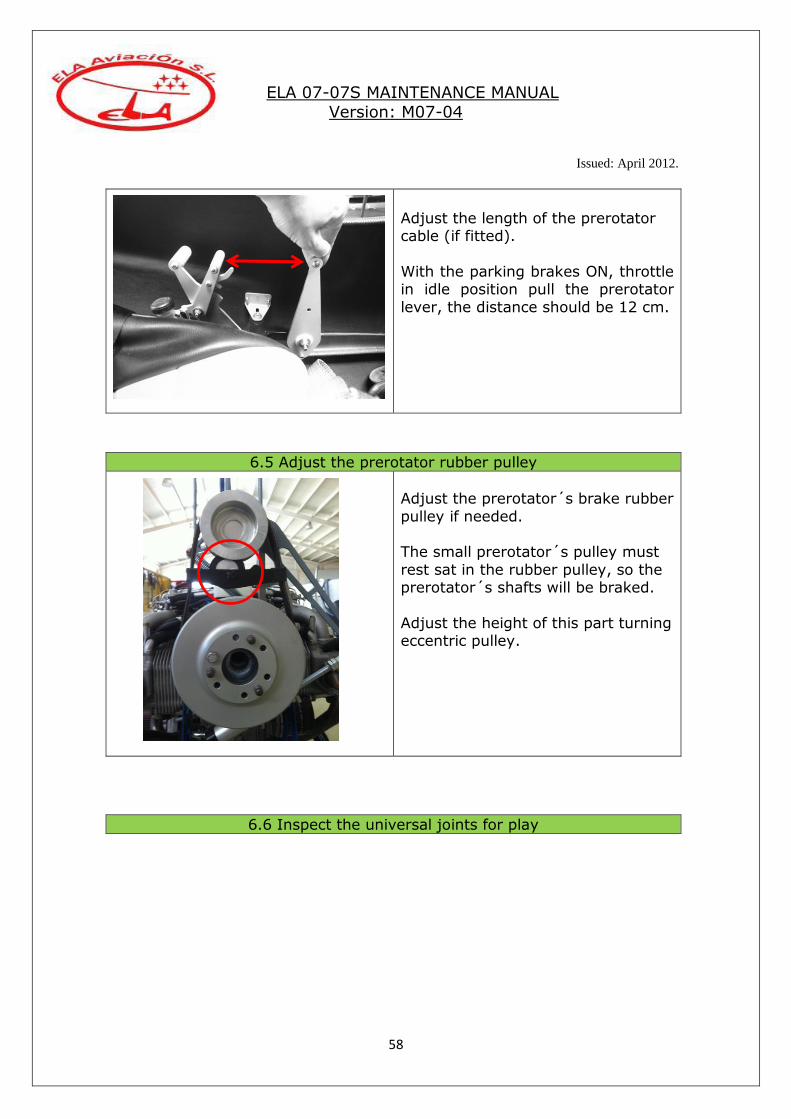
Adjust the length of the prerotator cable (if fitted).
With the parking brakes ON, throttle in idle position pull the prerotator
lever, the distance should be 12 cm.
6.5 Adjust the prerotator rubber pulley
Adjust the prerotator´s brake rubber
pulley if needed. The small prerotator´s pulley must
rest sat in the rubber pulley, so the prerotator´s shafts will be braked.
Adjust the height of this part turning eccentric pulley.
6.6 Inspect the universal joints for play
ELA 07-07S MAINTENANCE MANUAL
Version: M07-04
Issued: April 2012.
59
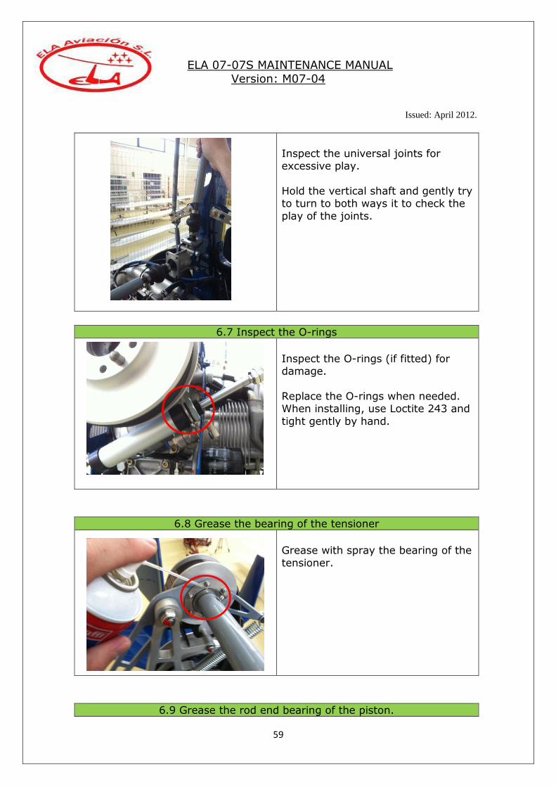
Inspect the universal joints for excessive play.
Hold the vertical shaft and gently try to turn to both ways it to check the
play of the joints.
6.7 Inspect the O-rings
Inspect the O-rings (if fitted) for damage.
Replace the O-rings when needed. When installing, use Loctite 243 and
tight gently by hand.
6.8 Grease the bearing of the tensioner
Grease with spray the bearing of the
tensioner.
6.9 Grease the rod end bearing of the piston.

ELA 07-07S MAINTENANCE MANUAL
Version: M07-04
Issued: April 2012.
60
Grease with spray the rod end bearing of the prerotator piston (if
fitted)
6.10 Clean and re-grease the universal joint
Remove the rubber covers of the universal joints for cleaning and re-
grease with Molycote.
6.11 Inspect the prerotator axle box.
Verify that the prerotator axle box has not oil leaks.
In case of leaks replace the oil seals.
6.12 Replace the bearing of the tensioner

ELA 07-07S MAINTENANCE MANUAL
Version: M07-04
Issued: April 2012.
61
Replace the bearing of the tensioner. Grease with Molycote before assembling.
6.12 Replace the prerotator cable bowden
Replace the prerotator cable Bowden (if fitted)
4.7 THROTTLE AND CHOKE SYSTEMS
ELA 07-07S MAINTENANCE MANUAL
Version: M07-04
Issued: April 2012.
62
7.1 Inspect the system for smooth operation
Operate the system from idle to full power position to confirm a smooth
operation.
7.2 Inspect the levers for damage
Inspect the front and rear levers for damage or malfunction.
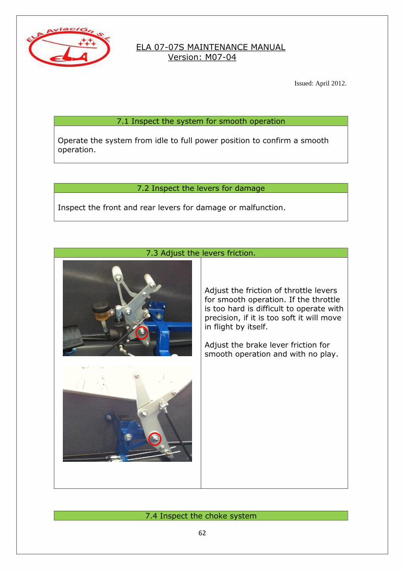
7.3 Adjust the levers friction.
Adjust the friction of throttle levers
for smooth operation. If the throttle is too hard is difficult to operate with
precision, if it is too soft it will move in flight by itself.
Adjust the brake lever friction for smooth operation and with no play.
7.4 Inspect the choke system

ELA 07-07S MAINTENANCE MANUAL
Version: M07-04
Issued: April 2012.
63
7.5 Inspect the locking wires
Inspect the locking wires of throttle
and choke systems. Replace if necessary.
7.6 Adjust carburettor synchronization
Operate the choke system to confirm its smooth operation.

ELA 07-07S MAINTENANCE MANUAL
Version: M07-04
Issued: April 2012.
64
Adjust the carburettor synchronization according with the latest issue of the Rotax maintenance manual.
7.7 Replace cables bowden
Replace carburettor and choke cables Bowden. Then it is necessary to
adjust the carburettor synchronization.
4.8 LANDING GEAR

ELA 07-07S MAINTENANCE MANUAL
Version: M07-04
Issued: April 2012.
65
8.1 Wheels
Verify tires pressure:
- Front wheel: 1,5 bar.
- Main wheels: 2 bar.
Check the tires for wear, replace when needed.
Inspect the wheel rims for cracks or damage.
Inspect the red marks between tires
and rims.
8.2 Verify sealing of landing gear bolts
Verify the sealing of the landing gear bolts in the aluminium landing
gear (new).
8.3 Re-tight landing gear bolts
In the old landing gear, made in composite, re-tight the 4 bolts that
fix it to the frame and re-tight the bolts that fix the wheels axles.

ELA 07-07S MAINTENANCE MANUAL
Version: M07-04
Issued: April 2012.
66
4.9 VARIOUS
8.4 Inspect landing gear
Inspect the old landing gear (composite), for cracks or damage.
8.5 Brake pads
Inspect the wheel brake pads for wear, replace when needed.
8.6 Clean and grease bearings
Clean and re-grease with Molycote
the wheels bearings in the old system (open rollers bearings).

ELA 07-07S MAINTENANCE MANUAL
Version: M07-04
Issued: April 2012.
67
4.10 ELECTRICAL/PNEUMATIC SYSTEMS
9.1 Inspect tail planes
Inspect tail planes and rudder for cracks or damage.
9.2 Re-tight tail planes attachment bolts
Re- tight tail planes attachment
bolts (4).
9.3 Replace tail planes bolts
Replace tail planes bolts, use Loctite 243.
9.4 Verify conditions of windscreens
Verify the absence of scratches or cracks. Polish them often with “Meguiar´s Mirror Glaze”.
9.5 Verify placards
Verify all placards, when fitted, are readable and in good conditions,
replace if necessary.

ELA 07-07S MAINTENANCE MANUAL
Version: M07-04
Issued: April 2012.
68
4.11 PROPELLER
10.1 Inspect the harnesses
Inspect the routing and connections of the electrical and pneumatic
harnesses for damage, wear, replacement of cable ties…
10.2 Check the battery level
Check the battery level in the old battery (Varta), refill with distilled water if necessary.
The new batteries DECA or Super-B don´t need maintenance.
10.3 Instrument panel
Remove the instrument panel for cleaning and inspect all wires and
connections for damage, wear…
10.4 Oil the compressor
Oil the compressor (new system) with engine oil.
Remove the cover of the compressor
and oil it with 3 or 4 drops of engine oil.
ELA 07-07S MAINTENANCE MANUAL
Version: M07-04
Issued: April 2012.
69
4.12 ENGINE
11.1 Inspection of the propeller
Inspect the propeller blades and hub for cracks or damages.
11.2 Re-tight the propeller bolts
Re-tight all the propeller bolts.
11.3 Propeller pitch
Verify that the pitch of the three propeller blades is the same.
11.4 Replace the propeller bolts
Replace the 6 propeller bolts of the centre of the hub.
11.5 Overhaul
Duc Windspoon propeller: Send to manufacturer for overhaul at 800
flight/hours.
ELA 07-07S MAINTENANCE MANUAL
Version: M07-04
Issued: April 2012.
70
The instructions for the engine maintenance and servicing are not included in this manual. To carry out engine maintenance appropriately, please refer to the updated engine maintenance manual.
12.1 Verify the sealing of engine bolts
Verify the red marks of the engine bolts.
12.2 Replace the engine silent-blocks
Replace the engine silent-blocks.
12.3 Replace the engine attachment bolts
Replace the engine attachment bolts.
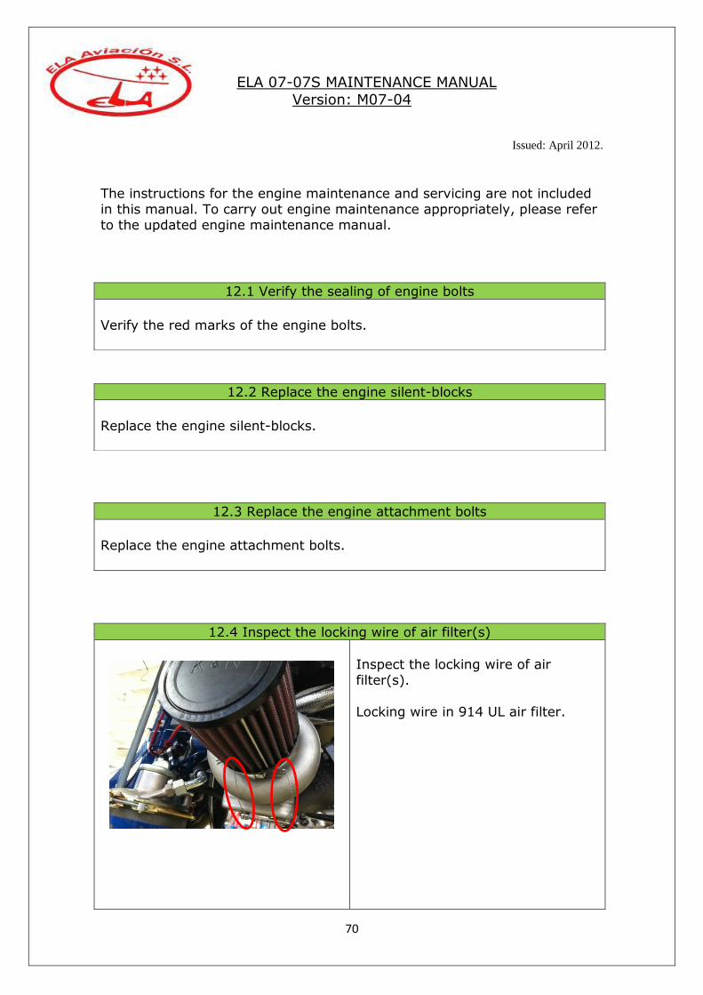
12.4 Inspect the locking wire of air filter(s)
Inspect the locking wire of air filter(s).
Locking wire in 914 UL air filter.

ELA 07-07S MAINTENANCE MANUAL
Version: M07-04
Issued: April 2012.
71
4.13 FUEL SYSTEM
Locking wire in 912 ULS air filters.
12.5 Inspect the exhaust system
Inspect the exhaust system for cracks or damage.
Inspect the after muffler for cracks or damage. Replace the springs and safety wire of the exhaust system of the 912
engine.

ELA 07-07S MAINTENANCE MANUAL
Version: M07-04
Issued: April 2012.
72
13.1 Clean the gascolator
Open and clean the gascolator.
13.2 Replace fuel filter
Replace the fuel filter.

ELA 07-07S MAINTENANCE MANUAL
Version: M07-04
Issued: April 2012.
73
4.14 COOLING SYSTEM
13.3 Clean the filters of the 914 pumps
Carefully remove the fuel filters
inside the electrical fuel pumps of the 914 and clean them.
13.4 Inspect hoses
Inspect the routing of the fuel hoses for wear or damage.
13.5 Replace the fuel hoses.
Replace the fuel hoses and clamps.
13.6 Perform fuel tank test
Check the inside filter of the fuel tank, procedure:
- Fill completely the tank with fuel.
- Open the outlet of the tank and measure the time to get one litre. - The max. time to get one litre should be less than 40 seconds.
ELA 07-07S MAINTENANCE MANUAL
Version: M07-04
Issued: April 2012.
74
4.15 OIL SYSTEM
14.1 Inspection of the system
Verify the absence of leaks in the system.
Inspect the conditions of the silent-blocks of the cooler. Check coolant level, the black tank should be full, the white tank should be
in the middle.
Inspect the rubber washer and spring of the cap of the black tank.
14.2 Replace the silent-blocks
Replace the silent-blocks of the cooler.
14.3 Replace hoses and coolant
Replace the rubber hoses and clamps of the system.
Replace the coolant. (See engine´s maintenance manual for approved coolants, 50%water / 50% pure antifreeze.
ELA 07-07S MAINTENANCE MANUAL
Version: M07-04
Issued: April 2012.
75
15.2 Replace hoses
Replace the hoses and clamps.
Section V – FUNCTIONAL TEST FLIGHT
15.1 Inspection of the system
Verify the absence of leaks in the system.
Inspect the hoses for wear or damage.
ELA 07-07S MAINTENANCE MANUAL
Version: M07-04
Issued: April 2012.
76
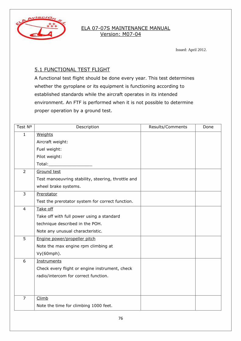
5.1 FUNCTIONAL TEST FLIGHT
A functional test flight should be done every year. This test determines
whether the gyroplane or its equipment is functioning according to
established standards while the aircraft operates in its intended
environment. An FTF is performed when it is not possible to determine
proper operation by a ground test.
Test Nº Description Results/Comments Done
1 Weights
Aircraft weight:
Fuel weight:
Pilot weight:
Total:_________________
2 Ground test
Test manoeuvring stability, steering, throttle and
wheel brake systems.
3 Prerotator
Test the prerotator system for correct function.
4 Take off
Take off with full power using a standard
technique described in the POH.
Note any unusual characteristic.
5 Engine power/propeller pitch
Note the max engine rpm climbing at
Vy(60mph).
6 Instruments
Check every flight or engine instrument, check
radio/intercom for correct function.
7 Climb
Note the time for climbing 1000 feet.

ELA 07-07S MAINTENANCE MANUAL
Version: M07-04
Issued: April 2012.
77
Airport elevation:
QNH:
Temp:
8 Controls
Test rotor and rudder controls in flight.
Note any unusual characteristic.
9 Speeds
Test general stability at speeds from 0 to 100
mph.
10 Trim
Test trim function at speeds from 0 to 100 mph.
11 Landing
Land with engine at idle speed and note any
unusual behaviour.
Comments/Remarks:
Date: Location:
Pilot Name: License Nº: