ist-1999-11729 metra d3ipd481/papers varios/v114si6g.pdf · 2018. 1. 15. · ist-1999-11729 metra...
TRANSCRIPT

IST-1999-11729 METRA
D3.2
Review and Selection of Relevant Algorithms
Contractual Date of Delivery to the CEC: 31 May, 2000
Actual Date of Delivery to the CEC: 1 June, 2000
Author(s): M. J. Heikkilä, K. Majonen, J. R. Fonollosa, R. Gaspa, M.A. Lagunas, M.Lamarca, X. Mestre, D. P. Palomar, A. Pérez-Neira, E. Tiirola, J. Ylitalo,M. Dowds, D. Lister.
Participant(s): All partners
Workpackage: WP3 Algorithm Study
Est. person months: 7.0
Security: Public
Nature: Report
Version: 1.1
Total number of pages: 65
Abstract:
This document reviews a number of relevant and potential multisensor transmit/receivealgorithms for the FDD and TDD modes of UTRA. Based on the presented review and theworking assumptions in METRA deliverable D3.1, the most applicable and promisingalgorithms are selected for further evaluation.
Keyword list: Multisensor algorithms, space-time processing

IST-1999-11729 METRA Doc.: IST-1999-11729/NMP-WP3-D3.2-V1.1
Title: Review and Selection of Relevant Algorithms 28 June, 2000
File: NMP-WP3-D3.2-V1.1 Page 2 of 65
0 EXECUTIVE SUMMARY
This document reviews a number of multiantenna receiver and transmitter algorithmsapplicable in FDD and TDD modes of UTRA. The theoretical capacity of multiple-inputmultiple-output (MIMO) channels is also discussed. In addition, the preliminary performanceresults of some multiantenna transmission techniques are compared. Based on the review, themost relevant and applicable techniques are selected for further studies in METRA project.
A MIMO channel can be represented as a number of parallel subchannels and the totalchannel capacity is thus the sum of the capacities of the individual channels. The number ofsubchannels equals to min(nT, nR) where the symbols denote the number of transmit andreceive antennas, respectively. It has been demonstrated that increasing the number ofantennas in the both ends results in a rapid increase in theoretical capacity. In practice, thecapacity is a random variable depending on the channel state and is thus measured with acertain outage probability. It should be noted that the capacity calculations do not assume orsuggest any practical technique to achieve a higher throughput and they serve as theoreticalupper bounds. This fact motivates the investigation of algorithms using multiple transmit andreceive antennas.
The studied algorithms have been devided in standard friendly and standard non-friendlytechniques. Standard friendly methods comply with the UTRA specifications and in mostcases rely on advanced signal processing using multiple receiver antennas. The preliminarytests show that UTRA transmit diversity schemes clearly outperform the single-antennatransmission and are thus chosen to be the basic techniques used for multiantennatransmission. At the receiver end, multiantenna RAKE serves as a basic receiver. Thisreceiver is not capable to perform optimal antenna and multipath combining in the presenceof temporally and spatially coloured noise. To overcome this drawback and to exploit thespatial dimension offered by a multiantenna array, linear MMSE receiver will be applied. Thelinear single-user MMSE receiver can also be extended to function in the temporal domain tosuppress the multiple access interference caused by multipath propagation. In addition,especially in the TDD system, maximum likelihood sequence estimators and multiuserreceivers will be considered for enhanced performance.
As standard non-friendly techniques, different space-time trellis coding stategies, joint spatio-temporal processing as well as techniques using parallel data streams (in a single channel)will be further studied. It has been demonstrated that space-time coding offers promisingcoding gains in addition to full diversity gain without causing any bandwidth expansion. Theconcept of parallel data streams (e.g. BLAST) relies directly on the large theoretical capacityof MIMO channels and will be considered as a candidate for achieving high data rates.Especially in the uplink, different beamforming and antenna hopping/selection strategies willalso be investigated as possible standard non-friendly techniques.
Many of the techniques selected for further studies improve the receiver sensitivity comparedto the currently standardized methods and, as such, increase the cell coverage or capacity. Toachieve higher data rates, their performance gain can be utilized by introducing a higher-level

IST-1999-11729 METRA Doc.: IST-1999-11729/NMP-WP3-D3.2-V1.1
Title: Review and Selection of Relevant Algorithms 28 June, 2000
File: NMP-WP3-D3.2-V1.1 Page 3 of 65
modulation or by reducing the rate of the error correcting code. Parallel data streams, on theother hand, directly increase the throughput. The exploitation of the improved performancedepends on the used system (FDD, TDD, uplink, downlink) according to the preferencesagreed within METRA project.

IST-1999-11729 METRA Doc.: IST-1999-11729/NMP-WP3-D3.2-V1.1
Title: Review and Selection of Relevant Algorithms 28 June, 2000
File: NMP-WP3-D3.2-V1.1 Page 4 of 65
DISCLAIMER
The work associated with this report has been carried out in accordance with the highest technical standards andthe METRA partners have endeavoured to achieve the degree of accuracy and reliability appropriate to the workin question. However since the partners have no control over the use to which the information contained withinthe report is to be put by any other party, any other such party shall be deemed to have satisfied itself as to thesuitability and reliability of the information in relation to any particular use, purpose or application.
Under no circumstances will any of the partners, their servants, employees or agents accept any liabilitywhatsoever arising out of any error or inaccuracy contained in this report (or any further consolidation,summary, publication or dissemination of the information contained within this report) and/or the connectedwork and disclaim all liability for any loss, damage, expenses, claims or infringement of third party rights.
IST-1999-11729 METRA Doc.: IST-1999-11729/NMP-WP3-D3.2-V1.1
Title: Review and Selection of Relevant Algorithms 28 June, 2000
File: NMP-WP3-D3.2-V1.1 Page 5 of 65
0 EXECUTIVE SUMMARY .........................................................................................................................2
1 INTRODUCTION .......................................................................................................................................7
2 CAPACITY OF MIMO CHANNELS .......................................................................................................8
2.1 INTRODUCTION..........................................................................................................................................8
2.2 CAPACITY FOR A GIVEN CHANNEL REALISATION......................................................................................8
2.2.1 Frequency-Nonselective SISO Channel.................................................................8
2.2.2 Frequency-Selective SISO Channel .......................................................................8
2.2.3 Frequency-Nonselective MIMO Channel ..............................................................9
2.2.4 Frequency-Selective MIMO Channel ....................................................................92.3 POWER ALLOCATION STRATEGIES ..........................................................................................................10
2.3.1 Uniform Distribution............................................................................................10
2.3.2 Water-Filling ........................................................................................................102.4 CAPACITY AS A RANDOM VARIABLE.......................................................................................................11
2.5 CAPACITY RESULTS.................................................................................................................................11
2.5.1 Capacity of a Flat SIMO/MISO vs. Flat MIMO Channels ..................................11
2.5.2 Capacity as a Function of Fading Correlation......................................................12
2.5.3 Capacity as a Function of Transmitted Power .....................................................13
2.5.4 Capacity as a Function of Number of Antenna Elements ....................................14
2.5.5 Capacity as a Function of Channel Knowledge ...................................................14
2.5.6 Capacity as a Function of Frequency-Selectivity.................................................152.6 CONCLUSIONS .........................................................................................................................................16
3 STANDARD FRIENDLY TECHNIQUES..............................................................................................19
3.1 FDD MODE OF UTRA.............................................................................................................................19
3.1.1 FDD Downlink.....................................................................................................19
3.1.2 FDD Uplink..........................................................................................................283.2 TDD MODE OF UTRA ............................................................................................................................37
3.2.1 TDD Downlink.....................................................................................................38
3.2.2 TDD Uplink..........................................................................................................42
4 STANDARD NON-FRIENDLY TECHNIQUES ...................................................................................43
4.1 JOINT TRANSMIT-RECEIVE SPATIO-TEMPORAL PROCESSING ..................................................................43
4.2 SPACE-TIME BLOCK CODES FOR UPLINK ................................................................................................43
4.3 SPACE-TIME TRELLIS CODES ..................................................................................................................43

IST-1999-11729 METRA Doc.: IST-1999-11729/NMP-WP3-D3.2-V1.1
Title: Review and Selection of Relevant Algorithms 28 June, 2000
File: NMP-WP3-D3.2-V1.1 Page 6 of 65
4.4 DELAY DIVERSITY...................................................................................................................................44
4.5 BLAST: BELL LABS LAYERED SPACE-TIME ARCHITECTURE .................................................................45
4.6 INTELLIGENT SELECTION OF TRANSMISSION/RECEPTION TECHNIQUE.....................................................45
5 PERFORMANCE OF STANDARDIZED METHODS.........................................................................46
5.1 SIMULATION ENVIRONMENT AND ASSUMPTIONS ....................................................................................46
5.1.1 Antenna Verification ............................................................................................465.2 PRELIMINARY SIMULATION RESULTS......................................................................................................47
6 PERFORMANCE OF SPACE-TIME CODED TRANSMISSION COMBINED WITHCONVOLUTIONAL AND TURBO CODING ................................................................................................51
6.1 STTC WITHOUT OUTER CHANNEL CODES ..............................................................................................51
6.2 STBC WITH CONVOLUTIONAL OUTER CODES.........................................................................................52
6.3 STTC WITH CONVOLUTIONAL OUTER CODES.........................................................................................54
7 SELECTION OF ALGORITHMS FOR FURTHER EVALUATION.................................................57
7.1 FDD MODE OF UTRA.............................................................................................................................57
7.1.1 Standard Friendly Techniques..............................................................................57
7.1.2 Standard Non-Friendly Techniques .....................................................................587.2 TDD MODE OF UTRA ............................................................................................................................58
7.2.1 Standard Friendly Techniques..............................................................................58
7.2.2 Standard Non-Friendly Techniques .....................................................................59
8 ABBREVIATIONS....................................................................................................................................60
9 REFERENCES ..........................................................................................................................................62

IST-1999-11729 METRA Doc.: IST-1999-11729/NMP-WP3-D3.2-V1.1
Title: Review and Selection of Relevant Algorithms 28 June, 2000
File: NMP-WP3-D3.2-V1.1 Page 7 of 65
1 INTRODUCTION
Many of the future wireless services to be provided by the 3rd generation mobilecommunications systems are likely to be used in low-mobility environments with limitedtemporal or multipath diversity. For this reason, conventional techniques, such as a RAKEreceiver applying interleaving in connection to channel coding, fail to provide sufficientdiversity thus causing a performance problem especially for high data-rate communications.The problem is most visible especially in the downlink where the strict power and sizerequirements of the terminals prohibit the use of the most advanced techniques for thereception. In the current specifications for the 3rd generations systems both open loop andclosed loop transmit diversity techniques applying two transmit antennas have been definedto better support higher data rates. Multiple antennas are located in the base stations to movethe complexity burden from terminals to base stations where it is more affordable.
While the current specifications already utilise the multiplicity of antennas to some degree, itis an open question what can be gained by further increasing the number of antennas in thebase station and/or in the user equipment (UE). There exist several well-known techniques,which could be applied in connection to multiple transmit or receive antennas to increase thecapacity, coverage or data rates of the system. In general, the field of investigation can beseparated into a number of parts:
UTRA FDD
• Downlink
• Multiple antenna transmission
• Multiple antenna reception
• Uplink
• Multiple antenna transmission
• Multiple antenna reception
UTRA TDD
• Downlink
• Multiple antenna transmission
• Multiple antenna reception
• Uplink
• Multiple antenna transmission
• Multiple antenna reception
In addition, different methods can be classified to be either standard friendly or standard non-friendly. It is the purpose of this document to shortly review some of the known techniquesapplicable in these contexts, and also point out some new possibilities. Some preliminaryperformance results are also presented. The most promising and applicable techniques arefinally selected to be further examined in METRA project.

IST-1999-11729 METRA Doc.: IST-1999-11729/NMP-WP3-D3.2-V1.1
Title: Review and Selection of Relevant Algorithms 28 June, 2000
File: NMP-WP3-D3.2-V1.1 Page 8 of 65
2 CAPACITY OF MIMO CHANNELSIn this section, the potentially achievable bit rate (capacity) over frequency-selectiveRayleigh multiple-input multiple-output (MIMO) channels for single-user communication isanalysed. The two extreme situations of fully correlated and completely uncorrelated fadingchannels are considered.
2.1 IntroductionRecently, MIMO channels arising from the use of multi-element antenna (MEA) systems thatuse spatial diversity at both the transmitter and the receiver have drawn considerable attention[Foschini98, Telatar00]. We will focus on the information-theoretic channel capacity, whichis a measure that represents the maximum achievable bit rate free of errors. Since the capacityis, indeed, a function of the random channel realisation, it is treated as a random quantity.
It will be shown that an nT-input, nR-output multiple antenna channel consists of n=min(nT,nR) parallel subchannels or eigenmodes. Therefore, the channel capacity of the MEA can becomputed as the sum of the individual subchannel capacities [Cover82]. Depending on theknowledge that the transmitter has about the channel, different power allocation strategiescan be used, leading to different capacities [Shiu98b].
It will also be observed that, when the fades are correlated, the channel capacity can besignificantly smaller than when the fades are i.i.d. [Shiu98a].
2.2 Capacity for a Given Channel RealisationThe capacity of a channel depends completely on the channel realisation, noise, andtransmitted signal power. In this section, the expression of the capacity is reviewed forSISO/MIMO frequency-nonselective/selective channels.
2.2.1 Frequency-Nonselective SISO ChannelFor a single-input single-output (SISO) channel, the received signal model is given by
)()()( tntxty +⋅=α (1)
and the capacity for such a model, as was derived by Shannon in 1948, is1
+= 2
22 1log ασ
n
PC . (2)
2.2.2 Frequency-Selective SISO ChannelIn case the channel is frequency-selective, the received signal can be expressed as
)()()(0
tntxtyL
lll +−=∑
=
τα (3)
or, equivalently, after subdividing the signal into flat-fading frequency bands as
1 The capacity expressions given throughout the paper are normalized with respect to the bandwidth, i.e., theyare given in terms of bits/sec/Hz.

IST-1999-11729 METRA Doc.: IST-1999-11729/NMP-WP3-D3.2-V1.1
Title: Review and Selection of Relevant Algorithms 28 June, 2000
File: NMP-WP3-D3.2-V1.1 Page 9 of 65
)()()()( fNfXffY +⋅α= . (4)
where now Y(f), α(f), X(f) and N(f) stand for the Fourier-transformed y(t), αt, x(t) and n(t)respectively. The capacity expression is then given by
∫
Φ+=
Wnn
dfff
fPW
C 22 )(
)()(1log1 α . (5)
with Φnn(f) the noise power spectral density, W the transmitting bandwidth andP(f)=E[|X(f)|2]. The transmitted power constraint is fixed as
∫ ≤W avPdffP )( . (6)
2.2.3 Frequency-Nonselective MIMO ChannelThe received signal model for the case of a flat MIMO channel is
)()()( ttt nHxy += , (7)
where x(t) is the transmitted vector, y(t) the received signal vector, n(t) the noise vector, andH the channel matrix that contains the fading from each transmission antenna to eachreceiving one (see Figure 1 for an illustration of a 4x4 flat MIMO channel).
h11
h12
h13h14
h44
Tx1
Tx2
Tx4
Tx3
Rx1
Rx2
Rx3
Rx4
h h h h11 12 13 14h h h hh h h hh h h h
21 22 23 24
31 32 33 34
41 42 43 44
H =
Figure 1. Illustrative example of a 4x4 flat MIMO channel.
The capacity of a flat MIMO channel is given by the expression [Telatar00, Foschini98]
+= H
n
C HQHI 221detlog
σ, (8)
where Q is the covariance matrix of the transmitted signal vector x(t). Note that thetransmission power constraint can be expressed as trace(Q)≤Pav.
2.2.4 Frequency-Selective MIMO ChannelFor this case, as for the frequency-nonselective SISO channel, the capacity is computed byintegrating over the utilised bandwidth
∫
Φ+=
W
H
nn
dfffffW
C )()()()(
1detlog12 HQHI (9)
with the power constraint as

IST-1999-11729 METRA Doc.: IST-1999-11729/NMP-WP3-D3.2-V1.1
Title: Review and Selection of Relevant Algorithms 28 June, 2000
File: NMP-WP3-D3.2-V1.1 Page 10 of 65
( )∫ ≤W avPdfftrace )(Q . (10)
2.3 Power Allocation StrategiesUnlike in the case of a flat SISO channel, where there is only one available channel, for thecase of frequency-selective and/or MIMO channels, the available transmission power can bedistributed over the antennas and/or frequency bands according to different strategies. Thepower allocation techniques will depend on the knowledge of the channel [Shiu98b].
2.3.1 Uniform DistributionThe uniform distribution of the available transmission power has to be used when the channelis unknown for the transmitter. Note that the channel is always assumed known by thereceiver. The capacity expression for the flat MIMO channel is then
+= HT
n
nPC HHI 22/
detlogσ (11)
and for a frequency-selective MIMO channel
∫
Φ+=
W
H
nn
T dffff
WnP
WC )()(
)(detlog1
2 HHI . (12)
2.3.2 Water-FillingNevertheless, in some situations, such as cases of reciprocity of the channel (TDD mode ofUTRA) or the use of explicit feedback information, the transmitter knows the channel and,therefore, can perform an optimum distribution of the power over the antennas and frequencybands. The maximisation of the capacity gives a power distribution technique commonlyreferred to as “water-filling” or “water-pouring” because it resembles the act of filling a bowl[Cover82].
The “water-filling” technique can be easily derived after performing the SVD2 of the channelmatrix HUDVH = and expressing the flat MIMO channel as a set of L=min(nT, nR) parallelchannels
)(~)(~)(~ ttt nxDy += (13)
or equivalently as
Lktntxty kkkk ≤≤+= 1 )(~)(~)(~ λ (14)
yielding the following optimum power allocation:
2 singular value decomposition.

IST-1999-11729 METRA Doc.: IST-1999-11729/NMP-WP3-D3.2-V1.1
Title: Review and Selection of Relevant Algorithms 28 June, 2000
File: NMP-WP3-D3.2-V1.1 Page 11 of 65
k
nk Kp
λσ 2
−= (15)
where K is a constant to meet power constraints. The global capacity is the sum of thecapacity of each subchannel. Note that for frequency-selective MIMO channels, the optimumpower allocation has to be done simultaneously over the set of parallel channels resultingfrom the spatial channel parallelisation and the orthogonal frequency bands.
2.4 Capacity as a Random VariableWe presume that the communication is carried out using bursts (packets). The burst durationis assumed to be short enough and the channel can be regarded as essentially fixed during aburst, but long enough that the standard information-theoretic assumption of infinitely longcode block lengths is a useful idealisation. In this quasi-static scenario, it is meaningful toassociate a channel capacity with a given realisation of the channel matrix H.
Since the channel capacity is a function of the random channel matrix, it can be regarded as arandom quantity whose distribution is determined by the distribution of H. In such cases, animportant measure for the channel capacity is the channel capacity at a given outageprobability q, denoted by Cq. It simply means that the channel capacity is less than Cq withprobability q or, in other words, it is greater than Cq with probability (1-q). In the following,the capacity results for different system configurations will be given by means of cumulativedistribution functions (CDF) of the capacity, expressing it as the probability (1-q) that thecapacity is greater than Cq.
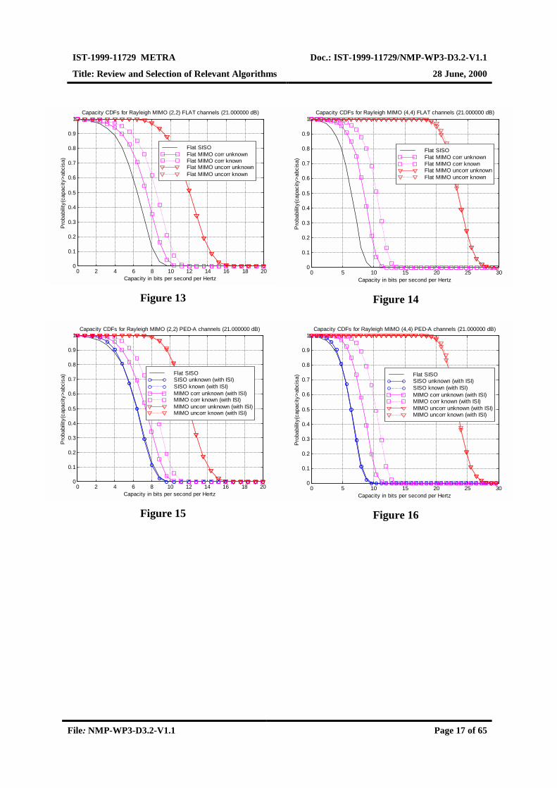
2.5 Capacity ResultsThe capacity results for the different system configurations are given as curves of CDF oroutage probability. They are computed using Monte-Carlo simulations based on 10,000random channel realisations. Different configurations will depend on many factors such asthe number of transmit and receive antennas (nT, nR), whether the channel is known or not atthe transmission side (it is always assumed known by the receiver), whether the fading isfully correlated or completely uncorrelated, the transmission power, and the frequency-selectivity of the channel (or its power delay profile). Note that, unless stated otherwise, thetransmitted power is kept constant for fair comparisons (SNR=21dB at each receivingantenna independent of the number of transmit antennas).
2.5.1 Capacity of a Flat SIMO/MISO vs. Flat MIMO ChannelsAs can be seen in Figure 2, where some capacity curves for different configurations ofuncorrelated flat SIMO and MISO Rayleigh channels are plotted, the capacity increases asthe number of either transmitting or receiving antennas does. Nevertheless, as can be seen inFigure 3, when arrays of antennas are utilised both in transmission and receptionsimultaneously, i.e. MIMO channels, the capacity boosts (note that for the case of (4,4) C=21bits/sec/Hz at Pout=0.1). This significant increase of capacity is due to the existence of parallelchannels, which do not exist in SIMO/MISO channels.

IST-1999-11729 METRA Doc.: IST-1999-11729/NMP-WP3-D3.2-V1.1
Title: Review and Selection of Relevant Algorithms 28 June, 2000
File: NMP-WP3-D3.2-V1.1 Page 12 of 65
0 2 4 6 8 10 120
0.1
0.2
0.3
0.4
0.5
0.6
0.7
0.8
0.9
1Capacity CDFs for uncorrelated flat-freq. Rayleigh channels (SNR = 21.000000 dB)
Capacity in bits per second per Hertz
Pro
babi
lity(
capa
city
>abc
isa)
SISO MIMO(1,2) Known MIMO(2,1)MIMO(1,4) Known MIMO(4,1)
Figure 2
0 5 10 15 20 25 300
0.1
0.2
0.3
0.4
0.5
0.6
0.7
0.8
0.9
1Capacity CDFs for uncorrelated flat-freq. Rayleigh channels (SNR = 21.000000 dB)
Capacity in bits per second per Hertz
Prob
abili
ty(c
apac
ity>a
bcis
a)
SISO Known MIMO(2,2)Known MIMO(2,4)Known MIMO(4,2)Known MIMO(4,4)
Figure 3
2.5.2 Capacity as a Function of Fading CorrelationThe effect of the fading correlation can be seen comparing Figure 2 with Figure 4 (for the(4,1) case, the capacity decreases from 8 to 6 bits/sec/Hz at Pout=0.1) and Figure 3 with (forthe (4,4) case, the capacity decreases from 21 to 8 bits/sec/Hz at Pout=0.1).
It can be seen how the huge potential capacity of the uncorrelated channels vanishes when thechannel becomes fully correlated. The explanation for that substantial difference is the factthat, when the channel gets correlated, the number of parallel channels decreases to the pointof just having one single channel, which corresponds to the fully correlated case. In suchcases, there is only a gain of beamforming.

IST-1999-11729 METRA Doc.: IST-1999-11729/NMP-WP3-D3.2-V1.1
Title: Review and Selection of Relevant Algorithms 28 June, 2000
File: NMP-WP3-D3.2-V1.1 Page 13 of 65
0 2 4 6 8 10 120
0.1
0.2
0.3
0.4
0.5
0.6
0.7
0.8
0.9
1Capacity CDFs for correlated flat Rayleigh channels (SNR = 21.000000 dB)
Capacity in bits per second per Hertz
Pro
babi
lity(
capa
city
>abc
isa)
SISO MIMO(1,2) Known MIMO(2,1)MIMO(1,4) Known MIMO(4,1)
Figure 4
0 5 10 150
0.1
0.2
0.3
0.4
0.5
0.6
0.7
0.8
0.9
1Capacity CDFs for correlated flat Rayleigh channels (SNR = 21.000000 dB)
Capacity in bits per second per Hertz
Probability(capacity>abcisa) SISO
Known MIMO(2,2)Known MIMO(2,4)Known MIMO(4,2)Known MIMO(4,4)
Figure 5
2.5.3 Capacity as a Function of Transmitted PowerIn Figure 6 and Figure 7, capacity CDF curves are plotted for uncorrelated flat MIMO (2,2)and (4,4) cases, respectively, as a function of the transmitted power (or equivalently thereceived average SNR at each antenna element). Note that for high SNR values, whereas thecapacity of the SISO channel increases 1 bit per 3dB increase of SNR, the capacity of a (n, n)channel increases n bits per 3 dB increase of SNR (see eq. (11)).

IST-1999-11729 METRA Doc.: IST-1999-11729/NMP-WP3-D3.2-V1.1
Title: Review and Selection of Relevant Algorithms 28 June, 2000
File: NMP-WP3-D3.2-V1.1 Page 14 of 65
0 5 10 150
0.1
0.2
0.3
0.4
0.5
0.6
0.7
0.8
0.9
1Capacity CDFs for uncorrelated flat Rayleigh channels
Capacity in bits per second per Hertz
Pro
babi
lity(
capa
city
>abc
isa)
SNR: 0, 3, 6, 9, 12, 15, 18, 21 dB
SISO Unknown MIMO(2,2)
Figure 6
0 5 10 15 20 25 300
0.1
0.2
0.3
0.4
0.5
0.6
0.7
0.8
0.9
1Capacity CDFs for uncorrelated flat Rayleigh channels
Capacity in bits per second per Hertz
Prob
abili
ty(c
apac
ity>a
bcis
a)
SNR: 0, 3, 6, 9, 12, 15, 18, 21 dB
SISO Unknown MIMO(4,4)
Figure 7
2.5.4 Capacity as a Function of Number of Antenna Elements
In Figure 8, the capacity CDF curves of flat MIMO (n, n) channels are plotted. As predictedby eq.(11), the capacity grows without limit as n increases for the case of uncorrelatedchannel.
0 10 20 30 40 50 600
0.1
0.2
0.3
0.4
0.5
0.6
0.7
0.8
0.9
1Capacity CDFs for unknown flat Rayleigh channels (SNR = 21.000000 dB)
Capacity in bits per second per Hertz
Pro
babi
lity(
capa
city
>abc
isa)
n = 1, 2, 3, 4, 5, 6, 7, 8, 9
Uncorr-MIMO(n,n)Corr-MIMO(n,n)
Figure 8
2.5.5 Capacity as a Function of Channel KnowledgeIn Figure 9, Figure 10, Figure 11, and Figure 12, capacity CDF curves are depicted for all thepreviously considered configurations with both uniform (channel unknown to the transmitter)and optimum (channel known to the transmitter) power allocation. The conclusion to bedrawn is that for the completely uncorrelated (n, n) case, it does not make a difference the use

IST-1999-11729 METRA Doc.: IST-1999-11729/NMP-WP3-D3.2-V1.1
Title: Review and Selection of Relevant Algorithms 28 June, 2000
File: NMP-WP3-D3.2-V1.1 Page 15 of 65
of one or another power allocation strategy. For the fully correlated case, however, there is asignificant difference on capacity.
0 2 4 6 8 10 120
0.1
0.2
0.3
0.4
0.5
0.6
0.7
0.8
0.9
1Capacity CDFs for uncorrelated flat-freq. Rayleigh channels (SNR = 21.000000 dB)
Capacity in bits per second per Hertz
Pro
babi
lity(
capa
city
>abc
isa)
SISO MIMO(1,2) Unknow n MIMO(2,1)Know n MIMO(2,1) MIMO(1,4) Unknow n MIMO(4,1)Know n MIMO(4,1)
Figure 9
0 5 10 15 20 25 300
0.1
0.2
0.3
0.4
0.5
0.6
0.7
0.8
0.9
1Capacity CDFs for uncorrelated flat-freq. Rayleigh channels (SNR = 21.000000 dB)
Capacity in bits per second per Hertz
Pro
babi
lity(
capa
city
>abc
isa)
SISO Unknow n MIMO(2,2)Know n MIMO(2,2) Unknow n MIMO(2,4)Know n MIMO(2,4) Unknow n MIMO(4,2)Know n MIMO(4,2) Unknow n MIMO(4,4)Know n MIMO(4,4)
Figure 10
0 2 4 6 8 10 120
0.1
0.2
0.3
0.4
0.5
0.6
0.7
0.8
0.9
1Capacity CDFs for correlated flat-freq. Rayleigh channels (SNR = 21.000000 dB)
Capacity in bits per second per Hertz
Pro
babi
lity(
capa
city
>abc
isa)
SISO MIMO(1,2) Unknow n MIMO(2,1)Know n MIMO(2,1) MIMO(1,4) Unknow n MIMO(4,1)Know n MIMO(4,1)
Figure 11
0 5 10 150
0.1
0.2
0.3
0.4
0.5
0.6
0.7
0.8
0.9
1Capacity CDFs for correlated flat-freq. Rayleigh channels (SNR = 21.000000 dB)
Capacity in bits per second per Hertz
Prob
abili
ty(c
apac
ity>a
bcis
a)
SISO Unknow n MIMO(2,2)Know n MIMO(2,2) Unknow n MIMO(2,4)Know n MIMO(2,4) Unknow n MIMO(4,2)Know n MIMO(4,2) Unknow n MIMO(4,4)Know n MIMO(4,4)
Figure 12
2.5.6 Capacity as a Function of Frequency-SelectivityIn Figure 13 - Figure 18, capacity CDF curves for MIMO(2,2) and MIMO(4,4)configurations over two frequency-selective channels (with delay profiles PED-A and VEH-A) are plotted. It can be observed how the increase of frequency diversity increases the slopeof the capacity curve, but does not shift it (as for the increase of n in the (n, n) case),

IST-1999-11729 METRA Doc.: IST-1999-11729/NMP-WP3-D3.2-V1.1
Title: Review and Selection of Relevant Algorithms 28 June, 2000
File: NMP-WP3-D3.2-V1.1 Page 16 of 65
improving the capacity at low probabilities of outage. In the limit of an infinitely frequencydiversity channel, the capacity CDF approaches a step function, which implies a deterministicvalue of the capacity (as for the nonfading case).
This analysis of capacity CDF has been performed over two extreme channel situations:completely uncorrelated fading and fully correlated fading. In a real situation (see[Fonollosa99, Shiu98a]), the correlation of the fades can be studied by analysing the PDF orthe CDF of the eigenvalues associated with the channel. For a low angle spread, the channelbecomes fully correlated, whereas for high angle spread, the channel decorrelates. Aninteresting possibility to further decorrelate the fades is the use of dual polarisation antennas.
2.6 Conclusions
After the present study of the capacity of Rayleigh MIMO channels, there are someinteresting conclusions to be drawn:
• The capacity of a MEA system generally decreases as the channel becomes morecorrelated or, in other words, as the angular spread decreases. For uncorrelated fading inMIMO channels, there is a large amount of capacity available.
• The performance of a wireless communication system that has multiple transmit antennasdepends on how transmitted power is distributed among these antennas. The differencebetween the capacities achieved by the uniform and optimum power allocation is smallwhen the fades associated with transmit-receive antenna pairs are independent, but canbecome very large when the fades are highly correlated. Therefore, the additionalcomplexity of optimum power allocation over uniform power allocation is justified onlyis the fades are strongly correlated.
As a final conclusion, we can say that uncorrelated MIMO channels are desirable overcorrelated ones and that the additional complexity of optimum power allocation (water-filling) over uniform one is justified only if the fades are strongly correlated.
IST-1999-11729 METRA Doc.: IST-1999-11729/NMP-WP3-D3.2-V1.1
Title: Review and Selection of Relevant Algorithms 28 June, 2000
File: NMP-WP3-D3.2-V1.1 Page 17 of 65
0 2 4 6 8 10 12 14 16 18 200
0.1
0.2
0.3
0.4
0.5
0.6
0.7
0.8
0.9
1Capacity CDFs for Rayleigh MIMO (2,2) FLAT channels (21.000000 dB)
Capacity in bits per second per Hertz
Pro
babi
lity(
capa
city
>abc
isa)
Flat SISO Flat MIMO corr unknown Flat MIMO corr known Flat MIMO uncorr unknownFlat MIMO uncorr known
Figure 13
0 5 10 15 20 25 300
0.1
0.2
0.3
0.4
0.5
0.6
0.7
0.8
0.9
1Capacity CDFs for Rayleigh MIMO (4,4) FLAT channels (21.000000 dB)
Capacity in bits per second per Hertz
Pro
babi
lity(
capa
city
>abc
isa)
Flat SISO Flat MIMO corr unknown Flat MIMO corr known Flat MIMO uncorr unknownFlat MIMO uncorr known
Figure 14
0 2 4 6 8 10 12 14 16 18 200
0.1
0.2
0.3
0.4
0.5
0.6
0.7
0.8
0.9
1Capacity CDFs for Rayleigh MIMO (2,2) PED-A channels (21.000000 dB)
Capacity in bits per second per Hertz
Pro
babi
lity(
capa
city
>abc
isa)
Flat SISO SISO unknown (with ISI) SISO known (with ISI) MIMO corr unknown (with ISI) MIMO corr known (with ISI) MIMO uncorr unknown (with ISI)MIMO uncorr known (with ISI)
Figure 15
0 5 10 15 20 25 300
0.1
0.2
0.3
0.4
0.5
0.6
0.7
0.8
0.9
1Capacity CDFs for Rayleigh MIMO (4,4) PED-A channels (21.000000 dB)
Capacity in bits per second per Hertz
Prob
abilit
y(ca
paci
ty>a
bcis
a) Flat SISO SISO unknown (with ISI) SISO known (with ISI) MIMO corr unknown (with ISI) MIMO corr known (with ISI) MIMO uncorr unknown (with ISI)MIMO uncorr known (with ISI)
Figure 16

IST-1999-11729 METRA Doc.: IST-1999-11729/NMP-WP3-D3.2-V1.1
Title: Review and Selection of Relevant Algorithms 28 June, 2000
File: NMP-WP3-D3.2-V1.1 Page 18 of 65
0 2 4 6 8 10 12 14 16 18 200
0.1
0.2
0.3
0.4
0.5
0.6
0.7
0.8
0.9
1Capacity CDFs for Rayleigh MIMO (2,2) VEH-A channels (21.000000 dB)
Capacity in bits per second per Hertz
Pro
babi
lity(
capa
city
>abc
isa) Flat SISO
SISO unknown (with ISI) SISO known (with ISI) MIMO corr unknown (with ISI) MIMO corr known (with ISI) MIMO uncorr unknown (with ISI)MIMO uncorr known (with ISI)
Figure 17
0 5 10 15 20 25 300
0.1
0.2
0.3
0.4
0.5
0.6
0.7
0.8
0.9
1Capacity CDFs for Rayleigh MIMO (4,4) VEH-A channels (21.000000 dB)
Capacity in bits per second per Hertz
Prob
abili
ty(c
apac
ity>a
bcis
a)
Flat SISO SISO unknown (with ISI) SISO known (with ISI) MIMO corr unknown (with ISI) MIMO corr known (with ISI) MIMO uncorr unknown (with ISI)MIMO uncorr known (with ISI)
Figure 18

IST-1999-11729 METRA Doc.: IST-1999-11729/NMP-WP3-D3.2-V1.1
Title: Review and Selection of Relevant Algorithms 28 June, 2000
File: NMP-WP3-D3.2-V1.1 Page 19 of 65
3 STANDARD FRIENDLY TECHNIQUES
3.1 FDD Mode of UTRA
Multisensor transmission algorithms can be separated into open loop and closed looptechniques. The former techniques do not require any feedback from the receiver back to thetransmitter while the latter techniques are based on feedback information. In FDD systemsuplink and downlink radio channels use separated frequency bands making the correspondingfading processes uncorrelated. Clearly, the transmitter cannot have knowledge of the radiochannel experienced by the downlink signal unless a feedback channel is utilised.
Closed loop techniques in FDD mode can potentially outperform open loop techniquesbecause more knowledge of the channel can be utilised. However, any kind of feedback isvulnerable in fast changing channels due to delays in the feedback link. Moreover, the datarate of the feedback is limited and the feedback data suffers from detection errors.
It should be pointed out that in some cases a certain transmission scheme requires a specificreceiver algorithm to be used while some other methods are transparent at the receiver. Alsoin these cases, the multiplicity of receive antennas can be utilised based on some of thetechniques presented in the later sections.
3.1.1 FDD Downlink
3.1.1.1 Basestation Multisensor Transmission AlgorithmsTable 1 summarises the use of open and closed loop techniques for the FDD mode of UTRA.Basically, the open loop mode is applied to all the logic channels while closed loop schemesare only intended for dedicated channels. In the open loop mode, two different techniques areproposed: Time-Switching Transmit Diversity (TSTD) for the Synchronisation Channel andSpace-Time Transmit Diversity (STTD) for the rest. The closed loop mode only includestransmit beamforming schemes.

IST-1999-11729 METRA Doc.: IST-1999-11729/NMP-WP3-D3.2-V1.1
Title: Review and Selection of Relevant Algorithms 28 June, 2000
File: NMP-WP3-D3.2-V1.1 Page 20 of 65
"X" – can be applied, "–" – not applied
Channel Open loop mode Closed loopTSTD STTD Mode
P-CCPCH – X –SCH X – –S-CCPCH – X –DPCH – X XPICH – X –PDSCH (associated with DPCH) – X XAICH – X –
Table 1 Applicability of open and closed loop techniques to different logic channels inthe FDD mode of UTRA.
3.1.1.1.1 Open Loop Techniques
As shown in Table 1, two distinct techniques are used in this mode: Time-SwitchingTransmit Diversity (TSTD) for the Synchronisation Channel and Space-Time TransmitDiversity (STTD) for the rest. The TSTD technique basically consists in an Antenna Hoppingstrategy where consecutive slots are sent from different antennas (see Figure 19). Assumingantennas sufficiently separated, transmissions of consecutive slots will undergo independentdistortion and fading, providing additional diversity at the mobile station.
Antenna 1
Antenna 2
acsi,0
acp
acsi,1
acp
acsi,14
acp
Slot #0 Slot #1 Slot #14
acsi,2
acp
Slot #2
Figure 19. Time-switching transmit diversity scheme for UTRA-FDD.
Figure 20 represents the second transmit diversity alternative for the open mode of UTRA-FDD, commonly referred to as space-time transmit diversity (STTD). The scheme basicallyconsists of a space-time block encoder based on the repetition of symbols across space andtime dimensions. In general much more powerful coding schemes can be employed, the onlyrestriction imposed being the block nature of the code.
The UTRA-FDD standard as defined at present only considers the scheme shown in Figure20, which is a 4x4 repetition code designed for two transmit antennas. The scheme is mostlyapplicable in large angle spread channels, such as in micro cells. Note that the block codingdoes not increase the required bandwidth.

IST-1999-11729 METRA Doc.: IST-1999-11729/NMP-WP3-D3.2-V1.1
Title: Review and Selection of Relevant Algorithms 28 June, 2000
File: NMP-WP3-D3.2-V1.1 Page 21 of 65
b0 b1 b2 b3
b0 b1 b2 b3
-b2 b3 b0 -b1
Antenna 1
Antenna 2Channel bits
STTD encoded channel bitsfor antenna 1 and antenna 2.
Figure 20. Space-Time Transmit Diversity scheme for UTRA-FDD.
3.1.1.1.2 Closed Loop Techniques
In the closed loop mode, the transmitter makes use of some feedback from the mobile station,which conveys information about the state of the channel in the downlink. The currentspecifications consider transmit beamforming techniques for the transmission in closed modeutilising two transmitting antennas (see Figure 21). Particularly, two distinct modes ofoperation are defined, namely:
• Mode 1: Distinct dedicated pilot signals are sent from each of the antennas (see Figure22) and the mobile station is allowed to request a change of only the phase of one out ofthe two transmit antennas.
• Mode 2: The same dedicated pilot signal is sent from all the antennas (see Figure 22) andthe mobile station is allowed to request a change of both phase and amplitude of one outof the two antennas.
Spread/scramblew1
w2
DPCHDPCCH
DPDCH
Rx
Rx
∑
CPICH1
Tx
∑
CPICH2
Ant1
Ant2
Tx
Weight Generation
w1 w2
Determine FBI messagefrom Uplink DPCCH
Figure 21. Closed mode transmit diversity in UTRA-FDD.

IST-1999-11729 METRA Doc.: IST-1999-11729/NMP-WP3-D3.2-V1.1
Title: Review and Selection of Relevant Algorithms 28 June, 2000
File: NMP-WP3-D3.2-V1.1 Page 22 of 65
More details on how the mobile station modifies the phase/amplitude of each antenna aregiven in [UTRA99b].
NPilot
NPilot
Antenna 1
Antenna 2
Slot i Slot i+1
NData2NData1
NTFCINData1
Antenna 1
Antenna 2
Slot i Slot i+1
NTPC
NTPC NData2
NTFCI
NData1 NTPC NTFCI NData2 NPilot
NData1 NTPC NTFCI NData2 NPilot
NData1
NData1
NTPC
NTPC
NTFCI
NTFCI
NData2
NData2
NPilot
NPilot
NPilotNData2NData1 NTPC NTFCI
NPilotNTFCINData1 NTPC NData2M
ode
1M
ode
2
Figure 22. Allocation of the dedicated pilot symbols across the space dimension formodes 1 and 2 in closed loop of UTRA-FDD.
3.1.1.2 Terminal Multisensor Reception AlgorithmsSince we are only interested in the reception of traffic data, we will focus on the demodu-lation at the mobile station of conventional and space-time block coded signals only.
3.1.1.2.1 Downlink Signal Model
Let us first consider the reception with a single antenna of a WCDMA-modulated signal asdefined in [UTRA99a]. For simplicity reasons we will assume that the conformation pulsehas roll-off = 0 so that a sampling rate of 1 sample/chip is enough to characterise the system.Gathering M samples3 of the received signal at one antenna into a column vector x:
[ ]TMnxnxn )1()()( −+=m
x (16)we can express this vector as:
( ) )()()()( nnnn nsChx +ℑ= (17)
where ( )hℑ is an Mx(N+1)SF Toeplitz convolution matrix associated with the channel of theuser of interest (length L) – see in Figure 23 the structure of this matrix –, N is the number oftransmitted symbols per parallel channel (multi-code transmission) in the observationwindow and SF the Spreading Factor. We assume perfect synchronisation with the user ofinterest and L<SF (if the last assumption were not true, the number of bits to be modelled inan observation window would be higher than N+1). The channel impulse response is denotedh and assumed constant within the observation window:
[ ]TLhhh m21=h (18)
3 The number of received samples M is assumed to be a multiple of the spreading factor of the system (in ourcase, denoted SF).
IST-1999-11729 METRA Doc.: IST-1999-11729/NMP-WP3-D3.2-V1.1
Title: Review and Selection of Relevant Algorithms 28 June, 2000
File: NMP-WP3-D3.2-V1.1 Page 23 of 65
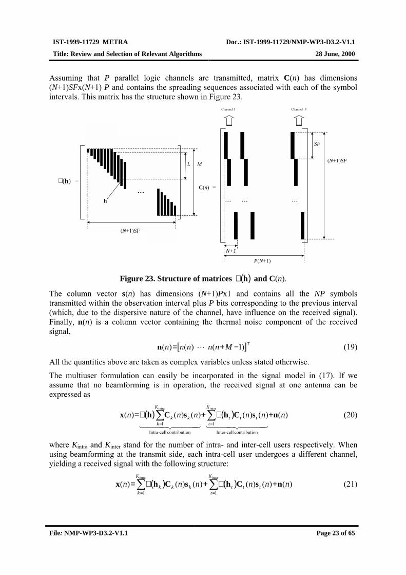
Assuming that P parallel logic channels are transmitted, matrix C(n) has dimensions(N+1)SFx(N+1) P and contains the spreading sequences associated with each of the symbolintervals. This matrix has the structure shown in Figure 23.
(N+1)SF
... ... ...
P(N+1)
N+1
SF
C(n) =
Channel 1 Channel P
L
=
...h
M
(N+1)SF
)(hℑ
Figure 23. Structure of matrices ( )hℑ and C(n).
The column vector s(n) has dimensions (N+1)Px1 and contains all the NP symbolstransmitted within the observation interval plus P bits corresponding to the previous interval(which, due to the dispersive nature of the channel, have influence on the received signal).Finally, n(n) is a column vector containing the thermal noise component of the receivedsignal,
[ ]TMnnnnn )1()()( −+= ln (19)
All the quantities above are taken as complex variables unless stated otherwise.
The multiuser formulation can easily be incorporated in the signal model in (17). If weassume that no beamforming is in operation, the received signal at one antenna can beexpressed as
( ) ( ) )()()()()()(
oncontributi cell-Inter
1
oncontributi cell-Intra
1
interintra
nnnnnnK
tttt
K
kkk nsChsChx +ℑ+ℑ= ∑∑
==NNN MNNN LKNNN MNNN LK
(20)
where Kintra and Kinter stand for the number of intra- and inter-cell users respectively. Whenusing beamforming at the transmit side, each intra-cell user undergoes a different channel,yielding a received signal with the following structure:
( ) ( ) )()()()()()(interintra
11
nnnnnnK
tttt
K
kkkk nsChsChx +ℑ+ℑ= ∑∑
==
(21)

IST-1999-11729 METRA Doc.: IST-1999-11729/NMP-WP3-D3.2-V1.1
Title: Review and Selection of Relevant Algorithms 28 June, 2000
File: NMP-WP3-D3.2-V1.1 Page 24 of 65
The model can be easily generalised to include the reception with more than one antenna.Consider first the single-user case with Q receive antennas at the mobile station. We denoteH the LxQ matrix containing the Q channel impulse responses:
[ ]QhhhH�21= (22)
We stack the column vectors corresponding to the signal received at each antenna – denotedxq(n) – into an MQx1 common column vector x(n),
( ) )()()()( nnnn nsCHx +ℑ= (23)
where
[ ][ ]
( ) ( ) ( )[ ]TTQ
T
TTQ
T
TTQ
T
nnn
nnn
hhH
nnn
xxx
ℑℑ=ℑ
=
=
�
�
�
1
1
1
)()()(
)()()(
(24)and C and s(n) remaining as in the single antenna case. If multiuser access is to beincorporated, the model in (21) becomes
( ) ( ) )()()()()()(interintra
11
nnnnnnK
tttt
K
kkkk nsCHsCHx +ℑ+ℑ= ∑∑
==
(25)
where now x(n) and n(n) have dimensions MQx1.
We must finally include the effect of a Space-Time encoding scheme at the transmission side.Assume that s(n) is the transmitted symbol sequence at the first antenna. The coded sequence(transmitted from the second antenna, for instance) can be expressed in general terms as
[ ][ ]
[ ][ ]
=
)(Im)(Re
)(Im)(Re
nn
nn
c
cssTs
s(26)
with T a 2(N+1)Px2(N+1)P unitary coding matrix (typically a permutation matrix with somechanged signs). Let us denote se(n) the extended real-valued vector containing the real andimaginary parts of s(n). The sequence of transmitted coded symbols can be expressed as
[ ][ ] )()(Im
)(Re)( nnnn e
c UsssUs =
= (27)
where U is a (N+1)P x2(N+1)P coding matrix generated as
[ ]VTU
IIV=
= ++ PNPN j )1()1( (28)
and I(N+1)P standing for the (N+1)Px(N+1)P identity matrix. With this formulation, thecontribution of a particular user to the received signal at a mobile station can be expressed as(for the case of two antennas)
( ) ( )[ ] )()()( 21 nnn ekkkkk sUCHVCH ℑ+ℑ (29)
IST-1999-11729 METRA Doc.: IST-1999-11729/NMP-WP3-D3.2-V1.1
Title: Review and Selection of Relevant Algorithms 28 June, 2000
File: NMP-WP3-D3.2-V1.1 Page 25 of 65
where now Hki stands for the channel impulse response from the i-th transmitting antenna to
the mobile station. If no beamforming is performed at the basestation (as it is the caseproposed in the standard), we will have Hk
i constant for all k associated with intra-cell users.
3.1.1.2.2 Modelling Assumptions
In order to propose useful receiver structures for the FDD mode of UTRA, the nature of theinterference and the particularities of the downlink transmitted signal must be taken intoaccount. The most relevant characteristics regarding the structure of the signal are:
• Long code sequences (period of the scrambling code: 218-1).
• Intra-cell interfering signals are transmitted synchronously with the desired signal andthrough the same channel as long as no transmit beamforming is used.
• Asynchronous inter-cell interference.
The use of long code sequences imposes harsh constraints on the receiver design. Almost alladvanced systems designed for the joint reception of CDMA signals are based on theassumption of short code sequences, with repetition periods of up to 256 chips. Directapplication of these techniques to the reception of long code sequences results in time-variantstructures involving the inverse of correlation matrices on a slot-by-slot basis. Since this istoo expensive from a computational point of view, it seems advisable to introduce somemodelling simplifications in order to reach simplified receiver structures.
A rather common simplification consists in modelling the spreading sequences of theinterfering users as independent circularly symmetric identically distributed complex randomvariables with zero mean, unit variance and finite fourth order moment. This would implythat for a general complex-valued column vector f of dimensions (N+1)Px1 and twointerfering users indexed by k and l
[ ] ( )
[ ] 0CffC0
IffCffC
=
≠=⊗=
)()(
)()(
nnE
lklkdiagnnE
Tl
Tk
SFH
Hl
Hk (30)
with ⊗ denoting Kronecker product.
3.1.1.2.3 Optimum Receiver Involving Second-Order Statistics Only
Assuming a known channel impulse response4, the optimum receiver would select the symbolsequence that maximises the likelihood function of the received signal conditioned on thissequence. If we assume that the code sequences associated with the interfering users belongto a finite alphabet, the likelihood function will depend in a rather complicated fashion onmoments higher than two, which are always tedious to compute. A much more simplifiedexpression for this likelihood function can be obtained modelling these code sequences ascircularly symmetric complex Gaussian-distributed variables, i.e.,
4 In practice, the channel impulse response will be estimated from the training sequence, which is not includedin our model for simplicity.
IST-1999-11729 METRA Doc.: IST-1999-11729/NMP-WP3-D3.2-V1.1
Title: Review and Selection of Relevant Algorithms 28 June, 2000
File: NMP-WP3-D3.2-V1.1 Page 26 of 65
( )( )
( )( ) ( )( ))()()()()()(expdet
1)( 1111
111)(1nnnnnnnf x
H
xn sCHxRsCHx
Rx s ℑ−ℑ−−
π= − (31)
where we have labelled the desired user with k=1 and matrix Rx represents the covariancematrix of the received signal
( ) ( ) ( ) ( ) M
K
j
Hjjj
K
k
Hkkkx IHHHHR 2
1
2
2
2interinter
σ+ℑℑα+ℑℑα= ∑∑==
(32)
In the last expression, 2kα represents the signal power corresponding to the k-th user and 2σ
the thermal noise power. Matrix Rx has been obtained using formula (30) and taking expectedvalue with respect to the interfering users’ symbols E[sk(n)sk(n)H] = αk
2 I(N+1)P. Thanks to the
assumption of randomised code sequences, this matrix does not depend on the time index n.In practice, however, the channel impulse responses must be estimated continuously, so thatmatrix Rx will have to be actualised with new channel estimations. Still, since abrupt changesof the channel impulse responses are not expected, we can always design adaptive methodsoperating on the inverse of Rx (using, for instance, the matrix inverse lemma) so that theinversion of the matrix is circumvented.
The optimum detector when transmitting with space-time block coding can be implementedselecting the symbol sequence that minimises the following expression:
21 1)()( −−=η
xnn e
STB RAsx (33)
where, for the case of two transmitting antennas,
( ) ( ) UCHVCHA )()()( 1211
11 nnn ℑ+ℑ= (34)
Now the contribution of the k-th user to the covariance matrix Rx can be expressed as
( ) ( )[ ]( )
( )( )( )
ℑℑ
⊗
⊗ℑℑα H
k
Hk
MSFH
k
SFHT
kM
kkk
diag
diag2
1212
21
21
HH
IIVVT
IVVTIHH (35)
where we have assumed E[ske(n)sk
e(n)T] = αk2/2 I(N+1)P. Matrix Tk denotes the coding matrix
corresponding to the k-th user and V is defined in (28). With all these definitions, theoptimum receiver operates as in the classical scheme, selecting s1
e(n) that minimises (33).
3.1.1.2.4 Linear Receivers
The maximum likelihood detector in (33) involves an exhaustive search among all thepossible symbol sequences potentially generated at the transmit side. Since this might resultrather expensive from the computational cost point of view, simpler algorithms – typicallybased on linear operations plus a decision device – are investigated here. If we denote L ageneral linear receiver, decisions will be obtained as
[ ] [ ])(sgn)(sgn)(ˆ1 nnn He xLys == (36)

IST-1999-11729 METRA Doc.: IST-1999-11729/NMP-WP3-D3.2-V1.1
Title: Review and Selection of Relevant Algorithms 28 June, 2000
File: NMP-WP3-D3.2-V1.1 Page 27 of 65
where L has dimensions MQx2P(N+1). The linear filter L is usually designed to minimise themean squared error between its output and the symbol sequence to be detected
{ }211 )()( nnE eH sxL −=η (37)
Depending on the statistical assumptions that we make when taking the expectation in (37),different receive structures will be derived. We now proceed to enumerate them.
• Rake Receiver. If the presence of interference is disregarded and the expectation is takenwith respect to the noise vector n(n) and symbols s1
e(n), we obtain
( ) ( )[ ]VTCHCHAL )()()()( 1211
11 nnnnrake ℑ+ℑ== (38)
which is a form of Rake receiver taking into account the space-time coding formulation.
• Wiener Filter. Both multiuser interference and noise are taken into account in theexpected value of (37):
)()( 1 nn xWiener ARL −= (39)
where now the covariance matrix Rx includes the contribution of noise plus interference.
• Decorrelating Detector. This approach yields data estimates minimising cost function2
12 )()()(W
sAx nnn e−=η (40)
with respect to the unknown data vector s1e(n), where W is a weighting matrix obtained
as5
[ ][ ]{ } xHee nnnnnnE RsAxsAxW =−−=− )()()()()()( 11
1 (41)
Carrying out the minimisation it is easy to show that
[ ] 111 )()()()( −−−= nnnn xH
xorDecorrelat ARAARL (42)
• MMSE Detector. In this case, a Bayesian approach is taken. The symbols are modelled aszero mean i.i.d. random variables and the detector is obtained as a conditional meanestimator [Kay93-p316]
( )[ ] 112
11 )()()()( −−
−− += NPxH
xMMSE nnnn IARAARL (43)
Other more simplified detectors can be obtained from the last two filters disregarding thepresence of interfering signals (Rx = IM):
[ ]( )[ ] 1
12Noint
1Noint
)()()()(
)()()()(−
−
−
+=
=
NPH
MMSE
HorDecorrelat
nnnn
nnnn
IAAAL
AAAL(44)
5 The election of the weighting matrix W follows from statistical considerations of the Asymptotically BestConsistent Estimator theory. See [Söderström89] for more details.
IST-1999-11729 METRA Doc.: IST-1999-11729/NMP-WP3-D3.2-V1.1
Title: Review and Selection of Relevant Algorithms 28 June, 2000
File: NMP-WP3-D3.2-V1.1 Page 28 of 65
One can also use a non-structured estimation of the covariance matrix Rx or makesimplifications in its presumed structure (low-rank models).
In any case, it is worth noting that any valid detection technique must rely on both the spaceand time dimensions of the problem. This is because of the presence of intracell interference,which can only be cancelled out in the temporal domain (note that all intracell interferencesignals come from the same direction of arrival).
3.1.2 FDD Uplink
3.1.2.1 Terminal Multisensor Transmission Algorithms
Mobile stations are not allowed to transmit with space-time coding capabilities in a standard-friendly environment. This means that only beamforming techniques can in principle be usedas transmitting schemes for a multi-antenna deployment at the mobile station. Simplerschemes – such as antenna hopping algorithms – will still be applicable at the mobile stationside.
3.1.2.2 Basestation Multisensor Reception Algorithms
Since only beamforming and pre-distortion techniques can be used at the mobile station, thereception schemes at the basestation in a standard-friendly environment will be restricted toclassical reception techniques, from RAKE receivers and other linear receivers tointerference cancellation schemes and linear and non-linear multiuser detectors. In any case,the introduction of multiple antennas at the mobile station does not impose any reformulationof the receiving strategies in base stations in classical standard-friendly environments.
3.1.2.2.1 Optimum Combining
3.1.2.2.1.1 Background
Optimum combining techniques have traditionally been used to combine the differentbranches in the antenna diversity. They can also be employed with the antenna arrays in orderto obtain a radiation pattern in which nulls take places towards the interfering signals whilethe main lobe enhances the desired signal. The optimum combining offers a solution foradaptive null steering and notchforming in the spatial domain [Widrow67, Winters84]. Theterms ‘adaptive beamforming’ and ‘interference rejection combining’ are also used instead ofthe term ‘optimum combining’.
The training signal based combining methods offer computationally inexpensive estimates ofthe signal and they can be used also without the knowledge of the AOA (Angle Of Arrival)[Widrow67, Winters84, Naguib96]. Moreover, the training signal based techniques do notmake any assumptions about the multipath angle spread and do not place any structuralconstraints on the antenna configuration itself. Due to that, the training signal basedalgorithms can be also be used to combine optimally the multiple branches in antennadiversity.
Figure 24 [Widrow67, Naguib96, Johnson93] depicts the general structure of the adaptiveantenna system. It consists of L antenna elements and the adaptive signal processor that

IST-1999-11729 METRA Doc.: IST-1999-11729/NMP-WP3-D3.2-V1.1
Title: Review and Selection of Relevant Algorithms 28 June, 2000
File: NMP-WP3-D3.2-V1.1 Page 29 of 65
generates a complex weight wl for each antenna element according to some algorithm. Theexact structure of the adaptive antenna system is dependent on the available information ofthe transmitted signal and the used adaptive algorithm.
.
.
.wL*
w2*
w1*
Adaptivesignal
processing
L antennaelements
Availableinformation
ΣΣΣΣBeamformer
output
t
Figure 24. Block diagram of an adaptive antenna system.
The optimum combining procedure will be next presented in the matrix notations[Widrow67, Winters84, Naguib98]. The received signal vector of L-antenna system isdenoted as
[ ] T21 Lrrr m=r . (45)
The beamforming weight vector w consists of independent complex-valued weights wl (l ∈{ 1,2,…, L} ) for each antenna element l and is denoted as
[ ] T21 Lwww �=w . (46)
The output signal of the beamformer denoted as t is the weighted sum of the antennaelements and given as
rwH=t (47)
where superscript H denotes the complex conjugation and transposition of the vector.
Most of the adaptive antenna algorithms depend on the measured field via the correlationfunction computed from the antenna signals. A useful measure of the correlation between theantenna elements is the spatial covariance matrix Rrr. That is a symmetric matrix of cross-

IST-1999-11729 METRA Doc.: IST-1999-11729/NMP-WP3-D3.2-V1.1
Title: Review and Selection of Relevant Algorithms 28 June, 2000
File: NMP-WP3-D3.2-V1.1 Page 30 of 65
correlations and autocorrelations of the input signals to the adaptive elements [Widrow67,Naguib96, Johnson93, Bar-Ness98, Monzingo80]. Generally Rrr is a function of the meanangle-of-arrival, the angle spread, the element spacing and the angular frequencies[Johnson93] and it is defined as
[ ]HE rrR ≡rr , (48)
where E[·] denotes the statistical expectation.
3.1.2.2.1.2 Optimum Combining Algorithms
Many algorithms and criteria for calculation of the weight vector w have been presented inthe literature. Minimisation of mean squared error (minimum mean squared error, MMSE),maximisation of signal-to-interference-plus-noise ratio (SINR), maximum likelihood (ML)and minimum noise variance (MV) have been used as optimisation criteria. Within all thecriteria the optimal weight vector turns out to be a function of signal strengths of the desiredand undesired signals and their covariances [Johnson93].
MMSE-algorithm that is often referred to as the optimum Wiener solution provides astraightforward way to define the weight vector w. It is based on the minimisation of themean square error between the known bit pattern and the beamformer output bit pattern[Widrow67, Naguib98, Johnson93, Damm96]. The difference between the desiredbeamformer output, i.e., the transmitted pilot symbol sp and the output of the beamformerforms the complex error signal e(k)
)()()( Hp kkske rw−= , (49)
where index k refers to a discrete time sample out of a sufficient statistics of size K[Naguib96, Damm96]. The quantity of interest is the expected value of the square of theerror, i.e., the mean-square-error, given by
[ ] [ ] [ ]( ) [ ][ ] ( ) wRwrw
wrrwrw H
rrH
rH
HH
ksE
kEkksEksEkeE
+−=
+−=
p2p
*p
2p
2
Re2)(
)()()(Re2)()(, (50)
where rrp is the cross-correlation function between the samples of the antenna signal vectorr(k) and the known pilot symbol sp(k) and · is the magnitude of the argument. Equation (50)is minimised by taking the partial derivative with respect to w and setting the result to zero asfollows
[ ]wRr
w rrr
keE22
)(0 p
2
+−=∂
∂= . (51)
The Wiener solution for the optimum antenna weights will be obtained by solving (51). Theoptimum weight vector is expressed as
IST-1999-11729 METRA Doc.: IST-1999-11729/NMP-WP3-D3.2-V1.1
Title: Review and Selection of Relevant Algorithms 28 June, 2000
File: NMP-WP3-D3.2-V1.1 Page 31 of 65
p1
opt rrr rRw −= , (52)
where superscript –1 is the inversion of the matrix. With the assumption that the desired signalcomponents sp,1, sp,2, ··· , sp,NxM are uncorrelated (M is the number of users and N the numberof multipath components) (52) can be expressed as [Naguib96, Bar-Ness98]
p1H
ps
p1
sopt 1 ruur
ruu
pp
rRrrR
w −
−
+= , (53)
where uuR is the spatial correlation matrix of the interference plus noise and ps is the desiredsignal power.
The weight vector w can be optimised also by maximising the SINR at the output of thebeamformer. It is assumed that the signal vector r(k) consists of the desired signal components(k) and the noise plus interference component u(k). Correspondingly the spatial correlationmatrix Rrr can be separated into the desired signal part Rss and interference plus noise partRuu. The SINR at the output of beamformer is given as [Naguib96, Bar-Ness98]
wRwwRw
T
T
uu
ss==power noise plus ceInterferen
power signal DesiredSINR . (54)
The optimal weight vector w SINR that maximises the SINR at the output of beamformer isgiven as [Winters84, Naguib96, Asztély95]
p1
SINR β ruu rRw −= (55)
where β is any nonzero complex constant and it does not affect the SINR at the output of thebeamformer.
The ML beamformer is obtained by finding the estimate that maximises the likelihoodfunction of the input signal vector. The optimum weight vector w ML that has been derived,e.g., in [Bar-Ness98, Monzingo80] is given as
p1H
p
p1
MLruur
ruu
rRrrR
w −
−
= . (56)
3.1.2.2.1.3 Optimum Combining for WCDMA
In this section the baseband signal model of the CDMA uplink will be presented inmathematical terms. After that, the structure of interference rejection combining RAKEreceiver in the presence of spatially coloured interference will be derived. The mathematicalformulation of the signal model used in this section is based on [Juntti97] and the derivationof the IRC RAKE demodulator is based on [Damm96, Asztély95, Muzynski98, Li95].

IST-1999-11729 METRA Doc.: IST-1999-11729/NMP-WP3-D3.2-V1.1
Title: Review and Selection of Relevant Algorithms 28 June, 2000
File: NMP-WP3-D3.2-V1.1 Page 32 of 65
Figure 25 illustrates the general model of multiuser CDMA system [Juntti97]. In this modelM users share the same communication media and the signals transmitted pass throughseparate and independent channels hm. The outputs of the channels are added to a commonnoise process z(t). This model can be used to depict the asynchronous uplink of the WCDMAcellular system.
h1(t)
h2(t)
...hM(t)
c1(p) (t)
s1(p) A1
(p)
s2(p) A2
(p)
sM(p) AM
(p)
c2(p) (t)
cM(p) (t)
z (t)
r (t)
Figure 25. CDMA uplink system model.
Let us consider a user m ∈ { 1,2,…, M} which transmits in the pth symbol interval t ∈ [(p-1)T,pT] complex (spread) signal xm(t) denoted as
)τ()( )()(m
pmm
pmm tcAstx −= , (57)
where sm(p)(t), Am, τm and cm
(p)(t) are the transmitted complex data symbol, amplitude oftransmitted signal of mth user, the time delay of mth user’s transmitted signal, and thesignature waveform of user m, respectively. The CDMA uplink is assumed to beasynchronous which means that the delays τm are uniformly distributed into the symbolinterval.
We assume multi antenna reception where each transmitted signal is received by L antennaelements. The radio channel for user m is considered as a linear filter with impulse responsematrix Hm
(p)(t). The rows in the matrix describe L antennas and each of them has anindependent channel for mth user. The channels consist of N complex fading taps hm,l,n each ofwhich has its own amplitude, phase and time delay. So the channel impulse response matrixfor mth user can be expressed as
[ ]T
pm,L,n
N
n
pm,L,n
pnm
N
n
pnm
pLm
pm
pm
thth
tttT
−
−=
=
∑∑==
)τ(δ)τ(δ
)()()(
)(
1
)()(,1,
1
)(,1,
)(,
)(1,
)(
m
mhhΗ. (58)

IST-1999-11729 METRA Doc.: IST-1999-11729/NMP-WP3-D3.2-V1.1
Title: Review and Selection of Relevant Algorithms 28 June, 2000
File: NMP-WP3-D3.2-V1.1 Page 33 of 65
The received CDMA signal at each antenna element is the convolution of the transmittedsignal xm and the corresponding row in the channel impulse response matrix Hm. Alsoadditive thermal noise will be summed up to the received signal. Thus, the complex envelopeof the received signal vector at the lth antenna element can be expressed as
∑∑∑
∑∑
=
−
= =
−
= =
+−−−=
+∗)−−=
N
nlm,n
pm
pm,l,n
P
p
M
mm
pm
lp
m,lmp
m
P
p
M
mm
pml
tzpTtchAs
tztpTtcAst
1m
)()(1
0 1
)(
)()(1
0 1
)(
)()ττ(
)()(τ()( Hr, (59)
where P is the number of symbols in the data packet, the asterisk ∗ denotes convolution andzl(t) is the complex zero mean additive white Gaussian noise process with two sided powerspectral density σ2.
Nr out of N multipath components (temporal RAKE fingers) of mth user are resolved in thetime domain by code matched filtering and are each received by L antenna elements. Eachdespread multipath component vector of length L is denoted by rm,n and it contains thereceived information symbol of mth user denoted by sm, the vector for complex fading channeltaps hm,n and the interference plus noise denoted by um,n. By assuming that we can collect asufficient number of statistics of the received signal by discretising each symbol period into Ksamples [Muzynski98, Glisic97, Proakis95], we can express the nth despread multipathcomponent of mth user as
( ) ( ) ( )kksk m,nmm,nm,n uhr += . (60)
A more compact notation will be obtained by stacking all the received and despreadmultipath components, rm,n(k) onto a vector rm(k) of length LNr as
( ) ( ) ( )
+
=+=
)(
)()(
)(
)(
)()(
,
2,
1,
,
2,
1,
k
kk
ks
k
kk
kksk
rr Nm
m
m
m
Nm
m
m
mmmm
u
uu
h
hh
uhroo
. (61)
The conventional single user matched filter receiver is not optimal for demodulation of themultiuser signal rl(t) [Juntti97, Glisic97, Proakis95]. Therefore the despread signal rm(k) has,besides the signal-of-interest (SOI), the interference-plus-noise term um, which containsmultiple access interference MAI caused by the other users (intercell and intracell MAI), selfinterference of desired signal due to multipath propagation, and despread thermal additivewhite Gaussian noise. The MAI term can be assumed temporally white when the spreadingfactor is large enough but it can be spatially coloured especially with variable bit rate users[Glisic97, Litva96, Viterbi96]. The error covariance matrix is denoted as Ruu,m and itillustrates the spatial properties of the mth user undesired signal components. Matrix is definedas

IST-1999-11729 METRA Doc.: IST-1999-11729/NMP-WP3-D3.2-V1.1
Title: Review and Selection of Relevant Algorithms 28 June, 2000
File: NMP-WP3-D3.2-V1.1 Page 34 of 65
( ) ( ) ( )[ ]kkk mmuu,mHE uuR = . (62)
The Gaussian variables um,n are mutually uncorrelated across sampling instants and alsoacross the different multipath components due to the nature of despreading process[Muzynski98, Proakis95]. Therefore Ruu,m can be expressed as
( ) ( ) ( )( )kkk uu,m,Nuu,m,uu,m r,diag 1 RRR �= . (63)
Assuming equal transmitting a priori probabilities for symbols sm and perfectly known bothchannel complex taps hm (channel estimates) and the error covariance matrix Ruu,m, theoptimum demodulation involves the maximisation of the log-likelihood function in sm[Asztély95, Muzynski98, Proakis95] as
{ }
( ) ( )( )∑
∏
=
−
−
=
+−−−=
−=
K
kmmmuu,mmmm
muu,mm
K
k uu,mLNmm
kskkksk
kkkk
sL
11
1H
,
1H
1
c)()()()()(
)()()(exp))((det
1ln),(
hrRhr
uRuR
rπ (64)
where det(·) denotes determinant, ln(·) the natural logarithm and c1 nonzero complexconstant, respectively. Assuming equal energy symbols sm, (64) can be further developed tothe form
( )
( )m*m
K
k
N
nm,nm,nm
K
km
N
nm,nm,n
mm
K
kuu,mmmm
s
kkks
kskk
ksksL
r
r
t
rw
rw
hRrr
Re2
c)()()(Re2
c)()()(Re2
c)()(Re2),(
21 1
H*
,2
1
*
1
H
21
1H
=
+
=
+
=
+=
∑ ∑
∑ ∑
∑
= =
= =
=
−
(65)
where superscript * denotes the complex conjugation. The maximum of the log-likelihoodfunction in sm contains Nr beamforming (IRC) weights wm,n(k), i.e., a weight vector for eachtemporal RAKE finger. As can be seen from (65) the complex weights wm,n are defined as
m,nuu,m,nm,n kk hRw )()( 1−= . (66)
The maximum of the log-likelihood function in sm contains, besides the terms wm,n, the vectortm of length K. The vector tm is the beamformer output defined as
)()()(1
H kkk m,n
N
nm,nm
r
rwt ∑=
= (67)
As a whole the optimum IRC receiver can be decomposed into Nr temporal RAKE fingerseach of which performs spatial IRC filtering on L antenna inputs using weights wm,n. The

IST-1999-11729 METRA Doc.: IST-1999-11729/NMP-WP3-D3.2-V1.1
Title: Review and Selection of Relevant Algorithms 28 June, 2000
File: NMP-WP3-D3.2-V1.1 Page 35 of 65
outputs of the fingers are summed and a correlation detector is applied to determine thesymbol with largest correlation metric [Proakis95].
The principal block diagram of the IRC RAKE receiver is illustrated in Figure 26. It consistsof L antenna elements, Nr temporal RAKE fingers, a code acquisition block, a SIR estimatorand a correlation detector. Each temporal RAKE finger has a block for the channel estimationand the IRC weight generation, 2L correlators for despreading a particular multipathcomponent and two summing blocks for combining the weighted antenna signals.
Delaydomain
Despr 1
Despr L
Despr 2
DPCCH
.
.
.
wL*
w1*
w2*
.
.
.
Re ( ) ΣΣΣΣNr SIR
estimationΣΣΣΣ
Despr 1
Despr L
Despr 2
ΣΣΣΣ
h , Ruu estimationweight generation
Re ( ) CorrelationdetectorΣΣΣΣ
Nr
DPDCH
MF 1
MF 2
MF L
Rakefinger
allocation
Nr
Nr Rake fingers
Code acquisition
Received data
symbol
SIRestimate
Figure 26. Principal block diagram of IRC RAKE receiver.
The code acquisition block contains an MF for each antenna element. The task of the MFs isto match the spread and scrambled pilot sequence to the complex conjugated antenna signalin order to resolve the delays of the channel impulse response taps. The code acquisitionblock also performs the RAKE finger allocation function in which the temporal RAKEfingers are allocated according to the total received energy per code phase.
Each temporal RAKE finger has two correlators for each antenna signal, namely the data andcontrol signals have their own correlators. After spatial combining weights wm,n are computedin each RAKE finger, they can be applied to the data channel to obtain the soft bit estimatesfor further temporal combining. After the spatial and temporal combining of the received datasignal the correlation detector is applied to determine the symbol with the largest correlationmetric [Muzynski98, Li95].
The IRC weights may also be used in the DPCCH channel for computation of post-combining SIR estimate, which is needed in the fast transmission power control. The SIR
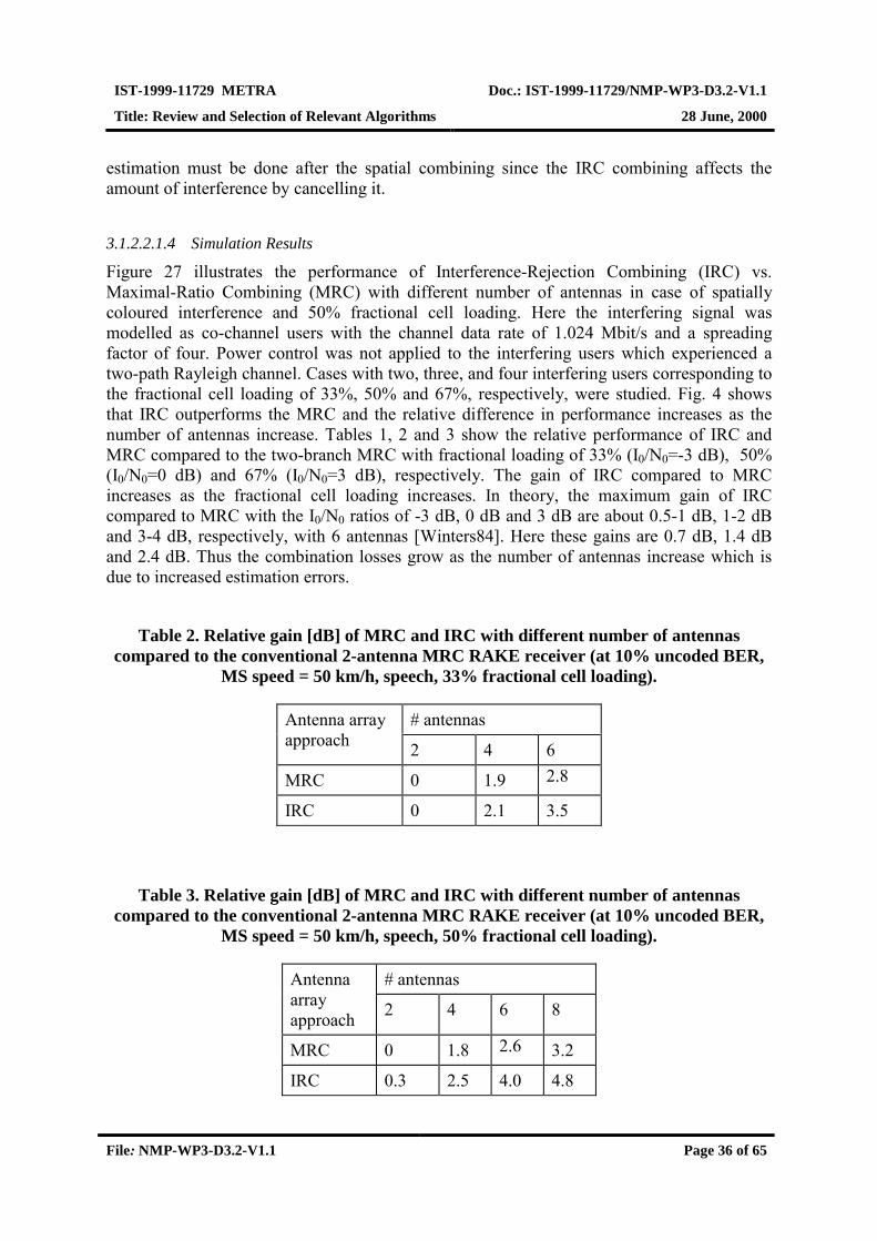
IST-1999-11729 METRA Doc.: IST-1999-11729/NMP-WP3-D3.2-V1.1
Title: Review and Selection of Relevant Algorithms 28 June, 2000
File: NMP-WP3-D3.2-V1.1 Page 36 of 65
estimation must be done after the spatial combining since the IRC combining affects theamount of interference by cancelling it.
3.1.2.2.1.4 Simulation Results
Figure 27 illustrates the performance of Interference-Rejection Combining (IRC) vs.Maximal-Ratio Combining (MRC) with different number of antennas in case of spatiallycoloured interference and 50% fractional cell loading. Here the interfering signal wasmodelled as co-channel users with the channel data rate of 1.024 Mbit/s and a spreadingfactor of four. Power control was not applied to the interfering users which experienced atwo-path Rayleigh channel. Cases with two, three, and four interfering users corresponding tothe fractional cell loading of 33%, 50% and 67%, respectively, were studied. Fig. 4 showsthat IRC outperforms the MRC and the relative difference in performance increases as thenumber of antennas increase. Tables 1, 2 and 3 show the relative performance of IRC andMRC compared to the two-branch MRC with fractional loading of 33% (I0/N0=-3 dB), 50%(I0/N0=0 dB) and 67% (I0/N0=3 dB), respectively. The gain of IRC compared to MRCincreases as the fractional cell loading increases. In theory, the maximum gain of IRCcompared to MRC with the I0/N0 ratios of -3 dB, 0 dB and 3 dB are about 0.5-1 dB, 1-2 dBand 3-4 dB, respectively, with 6 antennas [Winters84]. Here these gains are 0.7 dB, 1.4 dBand 2.4 dB. Thus the combination losses grow as the number of antennas increase which isdue to increased estimation errors.
Table 2. Relative gain [dB] of MRC and IRC with different number of antennascompared to the conventional 2-antenna MRC RAKE receiver (at 10% uncoded BER,
MS speed = 50 km/h, speech, 33% fractional cell loading).
# antennasAntenna arrayapproach 2 4 6
MRC 0 1.9 2.8
IRC 0 2.1 3.5
Table 3. Relative gain [dB] of MRC and IRC with different number of antennascompared to the conventional 2-antenna MRC RAKE receiver (at 10% uncoded BER,
MS speed = 50 km/h, speech, 50% fractional cell loading).
# antennasAntennaarrayapproach 2 4 6 8
MRC 0 1.8 2.6 3.2
IRC 0.3 2.5 4.0 4.8

IST-1999-11729 METRA Doc.: IST-1999-11729/NMP-WP3-D3.2-V1.1
Title: Review and Selection of Relevant Algorithms 28 June, 2000
File: NMP-WP3-D3.2-V1.1 Page 37 of 65
Table 4. Relative gain [dB] of MRC and IRC with different number of antennascompared to the conventional 2-antenna MRC RAKE receiver (at 10% uncoded BER,
MS speed = 50 km/h, speech, 67% fractional cell loading).
# antennasAntennaarrayapproach 2 4 6
MRC 0 1.7 2.3
IRC 0.5 3.0 4.7
-7 -6 -5 -4 -3 -2 -1 0 1 2
10-2
10-1
MRC vs. IRC in spatially coloured interference
SINR per antenna (dB)
UncodedBER
2-MRC2-IRC4-MRC4-IRC8-MRC8-IRC
Figure 27. Simulation result with MRC and IRC with different number of antennas(MAI modelled as spatially coloured noise, MS speed = 50 km/h, speech, fractional cell
loading 50%).
3.2 TDD Mode of UTRA
The 3GPP takes into account the possibility of using an array of antennas at the base stationbut not at UE. It should be noted that, unless stated otherwise, the algorithms are designed forclosed loop operation. In TDD systems no feedback is required for the knowledge of channelstate information because the same carrier frequency is used for both uplink and downlink.The only factor causing uncertainty to the knowledge of instantaneous channel conditions isthe channel time variation. It is important to remark that closed loop transmission does not

IST-1999-11729 METRA Doc.: IST-1999-11729/NMP-WP3-D3.2-V1.1
Title: Review and Selection of Relevant Algorithms 28 June, 2000
File: NMP-WP3-D3.2-V1.1 Page 38 of 65
imply an explicit feedback from the receiver, but only knowledge about the channel impulseresponse.
3.2.1 TDD Downlink
3.2.1.1 Basestation Multisensor Transmission Algorithms
3GPP envisages two open loop transmit diversity methods (suitable for common or broadcastchannels) and a closed loop beamforming approach (intended for dedicated channels, DPCH)[3GPP224].
3.2.1.1.1 Time Switched Transmit Diversity for Open Loop
This scheme can be employed for the SCH (Synchronisation Channel). It simply alternatesbetween the available antennas on a slot-by-slot basis (see Figure 28).
S-SCH
FIR RF
P-SCH
Ant 2
FIR RF
Ant 1
Switching Control
Figure 28. Scheme of the TSTD.
3.2.1.1.2 Block Space Time Transmit Diversity for Open Loop
Block STTD may be employed for the Primary Common Control Physical Channels (P-CCPCH). This scheme requires a different midamble per antenna so that the differentchannels can be estimated properly (see Figure 29).
BlockSTTDEncoder
Tx.Antenna 1
Tx.Antenna 2
Encoded and Interleaved Data
Midamble 2
MUX
MUX
Midamble 1
SPR-SCR
SPR-SCR Symbols, 2 data fields
Figure 29. Scheme of the block STTD.

IST-1999-11729 METRA Doc.: IST-1999-11729/NMP-WP3-D3.2-V1.1
Title: Review and Selection of Relevant Algorithms 28 June, 2000
File: NMP-WP3-D3.2-V1.1 Page 39 of 65
3.2.1.1.3 Narrowband Beamforming
For the closed loop downlink diversity scheme, the 3GPP proposes a narrowbandbeamforming approach [3GPP224], one different beamforming per each user (see Figure 30).Since each UE will see a different single equivalent antenna, one midamble per user has to beused. Note that in TDD mode of UTRA, unlike in FDD mode, the closed loop operation isbased on the property of the reciprocity of the uplink and downlink channels, which is a validassumption as long as the delay between channels is small compared to the coherence time ofthe channel.
MUX
INTENCData
Midamble w1
w2
FIR RF
FIR RF
Uplink channel estimate
ANT1
ANT2SPR+SCR
Figure 30. Scheme for the narrowband downlink beamforming.
Weighting factors w1 and w2 are computed on a per slot and per user basis by the base stationaccording to a specific algorithm and using the estimated uplink channel. For thedetermination of the beamforming weights, the 3GPP Technical Specification (TS) gives twopossible examples:
1. Selective Transmit Diversity (STD). This technique uses either {w1=1, w2=0} or {w1=0,w2=1}, that is, employing the antenna receiving the highest power.
2. Transmit Adaptive Antennas (TxAA). In a generic sense, the weights will maximise thedelivered power to the desired user according to
HwHw HHP = (68)
where [ ]NhhhH �21= , and ih is the uplink estimated channel impulse response forith antenna (reciprocity).
3.2.1.1.4 Joint Predistortion
This technique aims to reduce the complexity of the receiver, i.e., UE, from acomputationally expensive joint detection scheme to a simple matched filtering by increasingthe complexity burden of the transmitter, i.e., the BS.
It is based on predistorting the multiuser signal to be transmitted from the BS to the UEs in ajoint way. The reception of this properly predistorted signal will be, in an ideal situation, a

IST-1999-11729 METRA Doc.: IST-1999-11729/NMP-WP3-D3.2-V1.1
Title: Review and Selection of Relevant Algorithms 28 June, 2000
File: NMP-WP3-D3.2-V1.1 Page 40 of 65
signal free of intracell interference and ISI, allowing the utilisation of simple receivingschemes.
3.2.1.2 Terminal Multisensor Reception Algorithms
The signal model developed for the FDD mode of UTRA can easily be applied to the TDDmode, bearing in mind the following specific considerations for the current scenarios:
• Presence of guard intervals between slots (this obviates the need for modelling theinfluence of past symbols in the received signal, at least when the observation window istaken equal to a slot period).
• Use of short spreading codes in both up and down links.
• No space-time coding schemes in standard-friendly scenarios (only traffic channels aretaken into account).
According to this, the received signal at the mobile station can be modelled as (see section3.1.1.2.1)
( ) ( ) )()()()(interintra
11
nnnnK
tttt
K
kkkk nsCHsCHx +ℑ+ℑ= ∑∑
==
(69)
where now the column vectors sk(n) have dimensions NPx1 and contain the NP symbolstransmitted within the observation interval (we do not consider the influence of past symbolsthanks to the insertion of a guard interval). Accordingly, matrices Ck have dimensionsNSFxNP, and do not depend on the time index due to the use of short code sequences.
It seems reasonable to consider that the user equipment has the knowledge of the spreadingcodes used by all the users receiving in the same slot (i.e., intracell interfering users). Thismight not be the case for intercell interference, making it sensible to consider its influenceunder the assumption of randomised codes.
Following the same procedure that in the FDD mode, and under the assumptions statedabove, we can easily derive the following optimum and sub-optimum receive structures.
3.2.1.2.1 Optimum Non-Linear Detector Using Second-Order Statistics
Under the assumption that the interference is Gaussian-distributed, the Maximum Likelihoodsequence estimator finds s1(n) that maximises
( ) ( ) ( )( ) ( )( ){ })()()()(expdet
1)( 1111
111)(1nnnnnf x
H
xn
sCHxRsCHxR
xs
ℑ−ℑ−−= −
π(70)
where now the covariance of the received signal takes the expression
( ) ( ) ( ) ( ) M
K
j
Hjjj
K
k
Hk
Hkkkkx IHHHCCHR 2
1
2
2
2interinter
σ+ℑℑα+ℑℑα= ∑∑==
(71)
Like in FDD mode, this matrix could be estimated taking into account its structure as shownin (71) or disregarding it and using the non-structured sample covariance matrix (suboptimumsolution).

IST-1999-11729 METRA Doc.: IST-1999-11729/NMP-WP3-D3.2-V1.1
Title: Review and Selection of Relevant Algorithms 28 June, 2000
File: NMP-WP3-D3.2-V1.1 Page 41 of 65
3.2.1.2.2 Linear Single-User Detectors
Like in the FDD mode, a set of linear detectors to be applied prior to a decision device can bederived minimising different optimisation criteria (see section 3.1.1.2.4 for details):
• Rake Receiver:
( ) 11 CHAL ℑ==rake (72)
• Wiener Filter:
ARL 1−= xWiener (73)
• Decorrelating Detector:
[ ] 111 −−−= ARAARL xH
xorDecorrelat (74)
• MMSE Detector:
[ ] 111 −−− += PNxH
xMMSE IARAARL (75)
Note that these detectors provide estimations of the complex valued data, and that they do notvary over time thanks to the assumption of short code sequences.
3.2.1.2.3 Optimum Multiuser Detection
Dropping the assumption that the intra-cell interference is Gaussian-distributed, theMaximum Likelihood sequence estimator finds s1(n) that maximises
( ) ( ) ( ) ( )
ℑ−
ℑ−−= ∑∑
=
−
=
intraintra
1
1inter,
1inter,)(
)()()()(expdet
1)(K
kkkkx
HK
kkkk
xn
nnnnnf sCHxRsCHxR
xs π
(76)
Note that the contribution from inta-cell interference is assumed deterministic, so that thecovariance of the received signal takes the expression
( ) ( ) M
K
j
Hjjjx IHHR 2
1
2inter,
inter
σ+ℑℑα=∑=
(77)
Once again, this matrix could be estimated taking into account its structure or disregarding itand using the non-structured sample covariance matrix. On the other hand, minimisation of(76) implies a search in a space whose dimension increases exponentially with the number ofintra-cell users Kintra. This motivates the use of linear multi-user detectors.
3.2.1.2.4 Linear Multiuser Detection
Following the procedure outlined in other sections, we now consider the detection of all theintra-cell interfering users. The different minimisation criteria give rise to the solutionsbelow.
• Rake Receiver:
( ) ( ) ( )[ ]intraintra2211 KKrake CHCHCHAL ℑℑℑ== l (78)
IST-1999-11729 METRA Doc.: IST-1999-11729/NMP-WP3-D3.2-V1.1
Title: Review and Selection of Relevant Algorithms 28 June, 2000
File: NMP-WP3-D3.2-V1.1 Page 42 of 65
• Wiener Filter:
ARL 1inter,
−= xWiener (79)
• Decorrelating Detector:
[ ] 11inter,
1inter,
−−−= ARAARL xH
xorDecorrelat (80)
• MMSE Detector:
[ ] 11inter,
1inter, intra
−−− += PNKxH
xMMSE IARAARL (81)
Since only the NP first symbols are of interest to the desired user, in practice we will truncatethe obtained receivers to the fist NP columns of L. When doing so, the expressions of thelinear multiuser receivers above turn out to be equal to those presented in Section 3.2.1.2.4.This can be easily shown by applying the classical formula of the Matrix Inversion Lemma.
3.2.2 TDD Uplink
If the UE is provided with an array of antennas, it can perform a narrowband beamforming tomaximise the transmitted power towards the BS. Other standard-friendly techniques, such asantenna selection based on downlink channel measurements can also be useful. In any case,the use of an antenna array at the user equipment must be completely transparent to thebasestation reception algorithms, which may range from beamforming techniques to multi-user detection algorithms or combinations thereof.
IST-1999-11729 METRA Doc.: IST-1999-11729/NMP-WP3-D3.2-V1.1
Title: Review and Selection of Relevant Algorithms 28 June, 2000
File: NMP-WP3-D3.2-V1.1 Page 43 of 65
4 STANDARD NON-FRIENDLY TECHNIQUES
4.1 Joint Transmit-Receive Spatio-Temporal Processing
One of the intended types of service, especially in TDD mode, will support data rates over 2Mb/s. This means that for a particular scenario of TDD mode, a single user may use a wholetime slot. In this specific case, and for the sake of the desired high bit rate, a joint spatio-temporal processing design distributed between the transmitter and the receiver in anoptimised way can be utilised either for uplink or downlink. This joint design is a standardnon-friendly approach because it requires co-operation between the transmit and receivesides, i.e., one side of the communication system relies on the fact that the other is also usinga joint design [Andersen98, Raleigh98, Yang94].
Such a standard non-friendly approach is expected to yield a significant improvement in thechannel throughput at the expense of a higher computational complexity.
For the case of multiuser environment, more complex joint transmit-receive spatio-temporalprocessing techniques can also be used.
4.2 Space-Time Block Codes for Uplink
STBC are standardised only for downlink channels. However, when using more than oneantenna at the mobile, it is also possible to transmit using STBC for uplink channels, and no‘a priori’ limitations have been identified, neither with respect to the air interface nor to thesignalling needed to specify when STBC are used.
In the TDD mode, STBC could also be considered as a transmission scheme in the downlinknot only for the broadcast channels but also for the dedicated data channels.
4.3 Space-Time Trellis Codes
Contrary to STBC, a space-time trellis code (STTC) is defined by a trellis in which eachtransition is labelled with a set of m-PSK symbols each of which assigned to a transmissionantenna [Tarokh98]. All transmit antennas use the same spreading code and their channels areassumed to undergo uncorrelated fading. Preferably STTC should to be decoded by usingmaximum-likelihood sequence estimation (MLSE) resulting in more complex receivers thanin case of STBC. Channels from all transmit antennas have to be estimated for appropriatedecoding. In addition to the diversity gain, these codes have been shown to offer some non-negligible coding gain.
Most of the STTCs presented in the literature are designed for two transmit antennas and forquasi-static, frequency-nonselective Rayleigh fading channels. This can limit theirperformance in UTRAN where the channels may be frequency selective. A more difficultproblem could be the successful concatenation of STTC with the outer channel codes(convolutional and turbo codes). STTC are designed to minimise FER by increasing thedistances of the code words. In this respect, STTC are weak codes because they are restricted

IST-1999-11729 METRA Doc.: IST-1999-11729/NMP-WP3-D3.2-V1.1
Title: Review and Selection of Relevant Algorithms 28 June, 2000
File: NMP-WP3-D3.2-V1.1 Page 44 of 65
not to cause any bandwidth expansion. While optimising FER performance, the bit errorprobability is uncontrolled. For some space-time trellis codes, the optimised structure ofSTTC actually causes more bit errors than when using, for example, unoptimised delaydiversity trellis. This kind of behaviour may have a negative effect on the outer codeperformance.
When an additional outer channel code is used, soft values should be fed to the outer decoderin order to improve the performance of the code. This implies that either a soft output viterbialgorithm (SOVA) [Hagenauer89] or any a posteriori probability algorithm (APP) (i.e. MAP,log-MAP, max-log-MAP) [Robertson97] should be used to decode the STTC. This increasesboth the decoding complexity and the decoding delay.
From a coding perspective STTC seem attractive since they can provide not only diversitybut also coding gain. An option is to decode both codes (STTC and outer code) in an iterativemanner, similarly to turbo codes. Preliminary results in TDMA based systems show thatiterative decoding offers a considerable performance gain.
4.4 Delay Diversity
In delay diversity (DD) transmission two or more uncorrelated transmission antennastransmit the same symbols with a delay offset. In general, the delay offset should a multipleof a chip interval thus increasing the number of separable multipaths. This increases thediversity order at the receiver. The receiver does not necessarily require any knowledge ofwhether DD is applied of not. However, the number of RAKE fingers in the receiver maylimit the applicability of this approach. For optimal performance the delay offset shouldexceed the channel delay spread making the impulse responses corresponding to the eachtransmit antennas completely distinct thus resulting in the maximum number of propagationpaths separable by the receiver.
Another problem of DD is the intersymbol interference (ISI) caused by the extra multipathsand the suboptimal autocorrelation properties of the spreading codes. The problem isespecially severe with low spreading factors but can be partly compensated for by usingadvanced receivers.
In a special case of a delay offset of one symbol interval, delay diversity can be seen as asimple space-time trellis code. In fact, the simplest STTC optimised for QPSK modulation(4-state STTC for two transmit antennas [Tarokh98]) equals to DD transmission with a delayoffset of one symbol interval. However, one should make a clear distinction between:
• DD creating artificial multipaths separable due to spreading code properties, and
• DD trellis code making two consecutive symbols overlap with same spreading code. Thesymbols cannot be separated by despreading.
While the former relies on autocorrelation properties of the code, the latter results ininseparable symbols which can be resolved by using MLSE.
It should be noted that STBC supplies the receiver at least the same diversity order as DD.Unfortunately no STBC offering optimal linear decoding with a complex constellation exists
IST-1999-11729 METRA Doc.: IST-1999-11729/NMP-WP3-D3.2-V1.1
Title: Review and Selection of Relevant Algorithms 28 June, 2000
File: NMP-WP3-D3.2-V1.1 Page 45 of 65
for more than two transmit antennas. This can make DD useful with larger antenna arrayswhen combined e.g. with STBC or beamforming.
4.5 BLAST: Bell Labs Layered Space-Time Architecture
BLAST is a new bandwidth-efficient transmitter architecture, which takes advantage of thespatial dimension by transmitting and detecting a number of independent co-channel datastreams (substreams) each one transmitted from different antenna [Foschini99], [Golden99],[Wolniansky98].
Basically, the bitstream (coded or uncoded data from previous blocks) is demultiplexed intodifferent substreams (one per each transmit antenna), encoded into symbols and fed to itsrespective transmit antenna.
Depending on how is the encoding of these substreams defined this architecture leads toVertical-BLAST (V-BLAST) or Diagonal-BLAST (D-BLAST).
The first encodes each substream independently from the others by a channel code (i.e.convolutional code) without introducing any inter-substream redundancy, hence each antennatransmits different bits encoded independently ones from the others, in contrast to STBC orSTTC where all bits are transmitted “directly or indirectly” from all antennas.
On the other hand D-BLAST introduces redundancy between all substreams through specificcoding strategy. This approach offers higher spectral efficiencies than V-BLAST, although italso requires higher computational complexity.
The detection process of all substreams is divided into three key aspects: interference nulling,interference cancelling and compensation. Interference nulling projects out interference fromthose substreams not yet detected, interference cancelling substracts out interference of thosesubstreams already detected, finally stronger substreams compensates weaker ones.
For the V-BLAST architecture a multiuser detector can also be considered since datatransmitted from each antenna is independent from data transmitted from other antennas.
4.6 Intelligent Selection of Transmission/Reception Technique
In general, there is no algorithm which achieves the best performance is every scenario buttypically each available technique is most effective in a certain environment. Theapplicability of a specific method is dependent on channel conditions such as the number ofmultipaths, angular spread, fading speed and interference level. Moreover, the used servicetype, data rate and quality requirements may affect the optimal choice oftransmission/reception scheme. Especially in TDD, due to the channel reciprocity, thetranceiver has a good possibility to select the used algorithm to meet the requirements aseffectively as possible. Intelligent selection of a transmission/reception method could bebased on predefined thresholds for a number of factors either measured or signaled through afeedback channel and on frequent signalling of the selected algorithm. The decisions can alsobe made at a system level to optimise the overall capacity.

IST-1999-11729 METRA Doc.: IST-1999-11729/NMP-WP3-D3.2-V1.1
Title: Review and Selection of Relevant Algorithms 28 June, 2000
File: NMP-WP3-D3.2-V1.1 Page 46 of 65
5 PERFORMANCE OF STANDARDIZED METHODS
The multiantenna transmission schemes currently in the standard serve as benchmark in theperformance evaluation of the techniques to be selected for further studies. Thesestandardised methods were described in Chapter 3. In the following, some preliminary resultsfor the techniques in the 3rd generation standard proposal are presented in UTRA FDD systemin different environments. In particular, we evaluate the performance of single-antennatransmission, STTD, closed loop mode 1 and mode 2.
5.1 Simulation Environment and Assumptions
The simulated system is UTRA FDD downlink without power control and interfering users.In the case of multiantenna transmission, two transmit antennas is assumed while the receiveralways uses a single antenna. The turbo coding scheme defined in the specification has beenapplied as a channel code (rate 1/3 with 10 ms interleaving). The desired user uses spreadingfactor 32 which results in channel bit rate 240 kb/s and user data rate 67.2 kb/s.
The receiver performs channel estimation using the common pilot channel. The delays of thechannel paths are assumed to be known by the receiver. The simulated fading channels are:
• 1-tap Rayleigh fading channel (3 km/h)
• ITU Pedestrian A (3 km/h, 2 channel taps)
• ITU Vehicular A (50 km/h, 5 channel taps)
For closed loop modes, a constant feedback bit error rate of 4% has been used withoutexplicitly simulating the detection of the feedback data.
5.1.1 Antenna Verification
In the closed loop modes, where a specific feedback from the UE to the BS is applied, it ispossible that the feedback information is received erroneously by the BS. UE preferablyestimates the complex channel amplitudes from the continuous common pilot channel whichis not affected by the phase rotation (in mode 1&2) or by the amplitude weighting (in mode2). To obtain the actual channel estimates, the tentative estimates are modified by UEassuming that BS has received the feedback without errors. However, in case of feedbackerrors, this approach results in UE detecting the diversity transmission with wrong channelestimates.
In closed loop mode 1, the two transmit antennas are assigned different, orthogonal pilotpatterns for the dedicated pilot channel (time-multiplexed within each slot). Because thededicated pilot symbols are weighted with the same complex weights as the data itself, it is

IST-1999-11729 METRA Doc.: IST-1999-11729/NMP-WP3-D3.2-V1.1
Title: Review and Selection of Relevant Algorithms 28 June, 2000
File: NMP-WP3-D3.2-V1.1 Page 47 of 65
possible to generate reference channel estimates which already include the effect of antennaweighting and compare the estimates to the estimates generated by using the common pilotchannel. Based on this comparison, it is possible to make a decision on whether the feedbackfrom UE to BS was received erroneously or not, and to compensate the effect of the error.This technique is referred to as antenna verification [UTRA99b]. According to the UTRAspecification antenna verification is not applied in closed loop mode 2. A reason for this isthe higher resolution of the antenna weighting when compared to mode 1 which makes such averification more difficult both in terms of reliability and complexity.
In the performance results, BER of 4% has been assumed for the feedback channel both inclosed loop mode 1 and 2, and two cases for antenna verification has been used when mode 1is applied:
• Ideal antenna verification (UE always detects feedback errors and knows which feedbackbits BS has actually used in its transmission)
• Actual antenna verification (UE does not know if there have been feedback errors, andtries to detect them)
Closed loop mode 2 applies always ideal antenna verification.
5.2 Preliminary Simulation Results
Graphs in Figure 31 to Figure 36 show BER and BLER (block error rate) of single-antennatransmission, STTD (space-time block code) and the closed loop modes. Here, one blockconsists of 15 slots and thus equals to a radio frame. The closed loop modes are assumed touse either ideal antenna verification (solid lines) or, in case of mode 1, actual antennaverification (dashed lines).
In can be noticed that in both 3 km/h channels the closed loop modes outperform STTD.With antenna verification this is true only in one tap channel. Also, it is visible that as thenumber of channel taps increases the potential gain from the closed loop modes decreases.Antenna weighting cannot separately control different multipaths which makes the optimalsolution a compromise between individual paths. In the 50 km/h channel, most probably alsothe feedback delay decreases the performance of the closed loop modes. STTD performs in arobust way in all the cases.

IST-1999-11729 METRA Doc.: IST-1999-11729/NMP-WP3-D3.2-V1.1
Title: Review and Selection of Relevant Algorithms 28 June, 2000
File: NMP-WP3-D3.2-V1.1 Page 48 of 65
Figure 31
Figure 32

IST-1999-11729 METRA Doc.: IST-1999-11729/NMP-WP3-D3.2-V1.1
Title: Review and Selection of Relevant Algorithms 28 June, 2000
File: NMP-WP3-D3.2-V1.1 Page 49 of 65
Figure 33
Figure 34

IST-1999-11729 METRA Doc.: IST-1999-11729/NMP-WP3-D3.2-V1.1
Title: Review and Selection of Relevant Algorithms 28 June, 2000
File: NMP-WP3-D3.2-V1.1 Page 50 of 65
Figure 35
Figure 36

IST-1999-11729 METRA Doc.: IST-1999-11729/NMP-WP3-D3.2-V1.1
Title: Review and Selection of Relevant Algorithms 28 June, 2000
File: NMP-WP3-D3.2-V1.1 Page 51 of 65
6 PERFORMANCE OF SPACE-TIME CODED TRANSMISSION COMBINEDWITH CONVOLUTIONAL AND TURBO CODING
For the present only STBC are considered in the standardisation process of UMTS, but evenif any other space time code is considered, it will be probably concatenated to an outerchannel code (convolutional code rate 1/2 or 1/3 with K=9, or turbo code with rate 1/3 andK=4 for each constituent encoder).
In such a concatenated system where space-time codes and convolutional/turbo codes shareinformation from one to the other, several factors may influence the performance of theresulting combined system, among others: the frame (interleaver) length, which depends onthe data rate and the TTI (transmission time interval), estimation of reliability of the decodedbits (soft-values), channel estimation, etc.
In the following, preliminary results concerning some of the above mentioned factors arepresented and discussed.
6.1 STTC without Outer Channel CodesSpace-time trellis codes are designed to minimise frame error rate in single-path fadingchannels without causing any bandwidth expansion. Simulations indicate that STTC for e.g.8-PSK modulation [Tarokh98] provide 2-3 dB gain in BLER when compared to suboptimaldelay diversity (DD) trellis code which only guarantees the optimal diversity gain[Heikkilä00], see Figure 37. The performance of the delay diversity code is, in turn,comparable to STBC, which offers the same order of diversity but does not suffer fromsimilar SNR loss due to ISI.
However, BER plays a more significant role when the performance after the outer channeldecoding is considered. The tests show that optimised STTC are not able to improve the biterror rate achieved by the simple delay diversity code. Moreover, when the number of statesin STTC is increased, BER may even get worse as seen in Figure 38 [Heikkilä00]. Thus, it isexpected that concatenation of STTC with outer convolutional or turbo codes may beproblematic. In the literature, STTC is normally presented concatenated to some block errorcorrecting code [Naguib98] which are known to be inferior to the channel codes currently inthe specification.

IST-1999-11729 METRA Doc.: IST-1999-11729/NMP-WP3-D3.2-V1.1
Title: Review and Selection of Relevant Algorithms 28 June, 2000
File: NMP-WP3-D3.2-V1.1 Page 52 of 65
Figure 37. BLER of different space-time trellis codes and single-antenna transmission.
Figure 38. BER of different space-time trellis codes and single-antenna transmission.
6.2 STBC with Convolutional Outer CodesFigure 39 shows the concatenation of a STBC and a convolutional code separated with aninterleaver. The metrics to generate soft-output values out from the STBC decoder are alsodetailed. After deinterleaving these metrics feed the Viterbi algorithm.

IST-1999-11729 METRA Doc.: IST-1999-11729/NMP-WP3-D3.2-V1.1
Title: Review and Selection of Relevant Algorithms 28 June, 2000
File: NMP-WP3-D3.2-V1.1 Page 53 of 65
The BER curves of Figure 40 show the performance of this concatenated coding schemeusing as space-time code the Alamouti code or the orthogonal transmit diversity code (OTD).Also the repetition code (same symbol transmitted from each antenna) is plotted.
We observe that both space-time codes achieve almost the same performance. In fact, in mostcases, the STBC will provide diversity advantage and the convolutional or turbo code willproduce a coding gain. From this point of view any iteration process will be useless.
However an iterative procedure could be performed if higher order modulations were used(i.e. 8-PSK, 16-QAM, ...) between the demodulator-STBC decoder and the convolutionaldecoder. Assume that 8-PSK modulation is used, then each symbol represents 3 bits. Tocompute the soft-bit-values out of the demodulator the Euclidean distances between thereceived symbol and all the symbols of the constellation should be somehow combined. If ‘apriori’ information about the other 2 bits that represent the same symbol is supplied, then thesoft-bit-value can be computed using only the Euclidean distances between the receivedsymbol and those symbols form the constellation that, most likely, were transmitted(according to the ‘a priori’ information).
*122
*12
22
21
*122
*1
22*111
22
212
*2
*11
)(
)(
αααααα
αααααα
nnsrr
nnsrr
+−+=+−
+++=+
Viterbi, M APCC, r=1/3,K=9
STBC decodersoft-(symbol)-
output
2 time slots
Uncodeddata
4-PSK
− *1
*2
21
xxxx
coded data
CC, r=1/3,K=9
Coded data
Inter-leaving
Deinter-leaving
‘A priori’ feedback ?
A) Encoder
B) Decoder
Figure 39. Space-time block encoder and decoder.
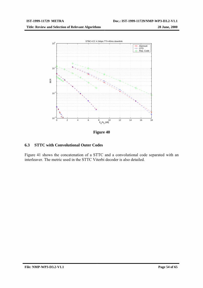
IST-1999-11729 METRA Doc.: IST-1999-11729/NMP-WP3-D3.2-V1.1
Title: Review and Selection of Relevant Algorithms 28 June, 2000
File: NMP-WP3-D3.2-V1.1 Page 54 of 65
0 2 4 6 8 10 12 14 16 1810
−3
10−2
10−1
100
STBC+CC 4.1kbps TTI=40ms downlink
Eb/N
0 [dB]
BE
R
Alamouti OTD Rep. Code
Figure 40
6.3 STTC with Convolutional Outer Codes
Figure 41 shows the concatenation of a STTC and a convolutional code separated with aninterleaver. The metric used in the STTC Viterbi decoder is also detailed.

IST-1999-11729 METRA Doc.: IST-1999-11729/NMP-WP3-D3.2-V1.1
Title: Review and Selection of Relevant Algorithms 28 June, 2000
File: NMP-WP3-D3.2-V1.1 Page 55 of 65
Uncodeddata
STTC, 4-states
4-PSK
CC, r=1/3,K=9
Coded data
Viterbi, MAPCC, r=1/3,K=9
STTC decoderViterbi, SOVA
MAP
Inter-leaving
Deinter-leaving
‘A priori’ feedback ?
codeddata
2
1 1,∑ ∑
= =
−R Tn
j
n
i
itji
jt qr α
A) Encoder
B) Decoder
Figure 41. Space-time trellis encoder and decoder.
0 2 4 6 8 10 12 14 16 1810
−4
10−3
10−2
10−1
100
STTC 4−state log−MAP + CC, downlink
Eb/N
0 [dB]
BE
R
384kbps TTI=40ms nr=1384kbps TTI=40ms nr=2384kbps TTI=40m nr=4 4.1kbps TTI=10ms nr=14.1kbps TTI=10ms nr=24.1kpbs TTI=10ms nr=4
Figure 42
In Figure 42 performance results of STTC (4-state code for 4-PSK) concatenated with aconvolutional code are shown. The dashed lines represent a service with a data rate of4.1Kbps and TTI = 40ms, solid lines show the BER for a service at 384Kbps and TTI = 10

IST-1999-11729 METRA Doc.: IST-1999-11729/NMP-WP3-D3.2-V1.1
Title: Review and Selection of Relevant Algorithms 28 June, 2000
File: NMP-WP3-D3.2-V1.1 Page 56 of 65
ms. It is possible to observe that the performance improves as the length of the inputsequence increases. This result will also be observed if turbo codes are used as outer codes.
The two lines plotted per each simulation represent the BER performance after 1 and 2iterations respectively. We do not observe any significant gain, however, simulations withother STTC with larger memory should be analysed. Perhaps the main drawback of thisconcatenated scheme is that in order to iterative decode it, the feedback information from theoutput of the convolutional decoder to the input of the STTC decoder should involve bothcoded and uncoded bits (notice that this is a serial concatenation). An extra computationaleffort is then required in order to feedback ‘a priori’ information in the form of soft-values.
Finally, we compare an 8-state DD trellis code (with one symbol delay offset betweenantennas), an 8-state STTC [Tarokh98] and Alamouti STBC for 8-PSK modulation when aconvolutional outer code of rate 1/3 has been used. Figure 43 shows the BLER of thesespace-time codes in known 1-tap Rayleigh channel. The unoptimised DD trellis results in abetter performance than the optimised STTC when concatenated with a strong convolutionalcode as discussed in Section 6.1. It should be noted that because DD trellis code (see Section4.4) causes ISI, it is more preferable to use STBC to obtain the same diversity order. TheSNR penalty caused by the ISI is clearly visible in Figure 43.
Figure 43. Comparison of DD, 8-state STTC and STBC with convolutional outer code.

IST-1999-11729 METRA Doc.: IST-1999-11729/NMP-WP3-D3.2-V1.1
Title: Review and Selection of Relevant Algorithms 28 June, 2000
File: NMP-WP3-D3.2-V1.1 Page 57 of 65
7 SELECTION OF ALGORITHMS FOR FURTHER EVALUATION
In this chapter, a number of multisensor transmit and receive algorithms have been listed tobe further studied in the project. This is to prioritise and focus the scope of the work but notnecessarily to restrict the field of investigation to the chosen items. The selection is in partbased on [Ylitalo00] describing the basic working assumptions for the project.
7.1 FDD Mode of UTRA
7.1.1 Standard Friendly Techniques
For the FDD mode, the emphasis is mainly on standard friendly techniques [Ylitalo00]. Thefocus is set on UE reception and transmission algorithms applying two antenna ports. Inaddition, only transmission of traffic data is considered. The methods to be tested are shownin Table 5.
Table 5. UTRA FDD standard friendly techniques (including reference cases)
Downlink Uplink
Single-antenna Single-antenna
STTD Beamforming
BS Tx
Beamforming (closed loop mode1&2)
UE Tx
Antenna hopping
RAKE RAKEUE Rx
Linear single-user MMSE
BS Rx
Linear single-user MMSE
In the table, RAKE refers to conventional maximal-ratio combining (MRC) over one or moreantenna ports. It is also possible to use some approximate or adaptive solutions for theMMSE receiver if found more appropriate.

IST-1999-11729 METRA Doc.: IST-1999-11729/NMP-WP3-D3.2-V1.1
Title: Review and Selection of Relevant Algorithms 28 June, 2000
File: NMP-WP3-D3.2-V1.1 Page 58 of 65
7.1.2 Standard Non-Friendly Techniques
Some standard incompatible techniques are studied in the later phase of the project. A fewpossibilities can initially be considered as shown in Table 6. The listed methods are subject tochanges.
Table 6. UTRA FDD standard non-friendly techniques
Downlink Uplink
STTC STTDBS Tx
BLAST architectures
UE Tx
DD
7.2 TDD Mode of UTRA
7.2.1 Standard Friendly Techniques
Several UE reception and transmission algorithms compatible with UTRA TDD specificationwill be studied. Only traffic channels are considered. The techniques to be evaluated areshown in Table 7.
Table 7. UTRA TDD standard friendly techniques (including reference cases)
Downlink Uplink
Single-antenna Single-antenna
Beamforming (TxAA) Beamforming
BS Tx UE Tx
Antenna selection
Single-user MLSE Multiuser MMSE
Multiuser RAKE
UE Rx
Multiuser MMSE
BS Rx

IST-1999-11729 METRA Doc.: IST-1999-11729/NMP-WP3-D3.2-V1.1
Title: Review and Selection of Relevant Algorithms 28 June, 2000
File: NMP-WP3-D3.2-V1.1 Page 59 of 65
7.2.2 Standard Non-Friendly Techniques
Also in the TDD mode a few standard incompatible techniques can be considered. The list ofin Table 8 is subject to changes during the project.
Table 8. UTRA TDD standard non-friendly techniques
Downlink Uplink
Joint Tx-Rx ST processing Joint Tx-Rx STprocessing
BS Tx/UE Rx
BLAST architectures
UE Tx/BS Rx
BLAST architectures

IST-1999-11729 METRA Doc.: IST-1999-11729/NMP-WP3-D3.2-V1.1
Title: Review and Selection of Relevant Algorithms 28 June, 2000
File: NMP-WP3-D3.2-V1.1 Page 60 of 65
8 ABBREVIATIONS
3GPP 3rd generation partnership projectAOA angle of arrivalAPP a posteriori probabilityBER bit error rateBLAST Bell Labs layered space-time architectureBLER block error rateBS base stationCC convolutional codeCDF cumulative distribution functionCDMA code division multiple accessCPICH common pilot channelD-BLAST diagonal-BLASTDD delay diversityDPCCH dedicated physical control channelDPCH dedicated physical channelDPDCH dedicated physical data channelFBI feedback informationFDD frequency division duplexFER frame error rateIRC interference rejection combiningISI intersymbol interferenceITU international telecommunication unionMAI multiple access interferenceMAP maximum a posterioriMEA multielement antennaMETRA multielement transmit and receive antennasMIMO multiple-input multiple-outputMISO multiple-input single-outputML maximum likelihoodMLSE maximum likelihood sequence estimationMMSE minimum mean-square errorMRC maximal-ratio combiningMS mobile stationMV minimum noise varianceOTD orthogonal transmit diversityP-CCPCH primary common control physical channelPDF probability density functionPSK phase shift keyingQAM quadrature amplitude modulationQPSK quadrature phase shift keyingRAKE rakeRX receiverSCH synchronisation channel

IST-1999-11729 METRA Doc.: IST-1999-11729/NMP-WP3-D3.2-V1.1
Title: Review and Selection of Relevant Algorithms 28 June, 2000
File: NMP-WP3-D3.2-V1.1 Page 61 of 65
SIMO single-input multiple-outputSINR signal-to-interference-plus-noise-ratioSIR signal-to-interference ratioSNR signal-to-noise ratioSOI signal-of-interestSOVA soft output Viterbi algorithmST space-time, spatio-temporalSTBC space-time block codeSTD selective transmit diversitySTTC space-time trellis codeSTTD space-time transmit diversitySVD singular value decompositionTDD time division duplexTDMA time division multiple accessTS technical specificationTSTD time-switching transmit diversityTTI transmission time intervalTX transmitterTxAA transmit adaptive antennaUE user equipmentUMTS universal mobile telecommunications systemUTRA universal terrestrial radio accessUTRAN universal terrestrial radio access networkV-BLAST vertical-BLASTWCDMA wideband code division multiple access
IST-1999-11729 METRA Doc.: IST-1999-11729/NMP-WP3-D3.2-V1.1
Title: Review and Selection of Relevant Algorithms 28 June, 2000
File: NMP-WP3-D3.2-V1.1 Page 62 of 65
9 REFERENCES
[3GPP224] 3GPP TS 25.221, “Physical channels and mapping of transport channels ontophysical channels (TDD)”, 3G TS 25.221 version 3.1.1 (1999-12),http://www.3gpp.org.
[Andersen98] J. Bach Andersen, “High Gain Antennas in a Random Environtment”,PIMRC’98, Boston, Vol. 3, pp. 1275-1279, 1998.
[Asztély95] D. Asztély, “Antenna Arrays in Mobile Communication Systems Fast Fadingand GSM Base Station Receiver Algorithms”, M.Sc. E.E. Thesis, RoyalInstitute of Technology, Stockholm, Sweden, 1995.
[Bar-Ness98] Y. Bar-Ness, “Adaptive Array Processing and Interference Cancellation”,Course Material, University of Oulu, 1998.
[Cover82] T.M. Cover, and J.A. Thomas, “Elements of Information Theory”, JohnWiley & Sons, New York, 1982.
[Damm96] H. Damm, “Smart Antennas in the GSM System”, M.Sc. E.E. Thesis,Aalborg University, Denmark, 1996.
[Heikkilä00] M.J. Heikkilä, K. Majonen, and J. Lilleberg, “Decoding and Performance ofSpace-Time Trellis Codes in Fading Channels with IntersymbolInterference”, PIMRC’2000, London, accepted for publication.
[Johnson93] D.H. Johnson, and D.E. Dudgeon, “Array Signal Processing, Concepts andTechniques”, Prentice Hall Inc., New Jersey, USA, 1993.
[Kay93] S.M. Kay, “Fundamentals of Statistical Signal Processing”, Prentice Hall,1993.
[Fonollosa99] J.R. Fonollosa, J.P. Kermoal, X. Mestre, P. Mogensen, D.P. Palomar, and K.Pedersen, “Algorithms for Flexible Multi-Standard Array Processing: Part 4,TDD Mode of UTRA”, Deliverable D711, AC347/UPC/A71/DR/P/008/a1,ACTS 0347 SUNBEAM project, 1999.
[Foschini98] G.J. Foschini, and M.J. Gans, “On Limits of Wireless Communications in aFading Environment when Using Multiple Antennas”, Wireless PersonalCommunications 6: 311-335, 1998.
[Foschini99] G.J. Foschini, G.D. Golden, R.A. Valenzuela, P.W. Wolniansky, “Simplifiedprocessing for high spectral efficiency wireless communication employing

IST-1999-11729 METRA Doc.: IST-1999-11729/NMP-WP3-D3.2-V1.1
Title: Review and Selection of Relevant Algorithms 28 June, 2000
File: NMP-WP3-D3.2-V1.1 Page 63 of 65
multi-element arrays”, IEEE Journal on Selected Areas in Communications,vol.17, no.11, p.1841-52, Nov. 1999.
[Glisic97] S. Glisic, and B. Vucetic, “Spread Spectrum CDMA Systems for WirelessCommunications”, Artech House Inc., Boston, USA, 1997.
[Golden99] G.D. Golden, G.J. Foschini, R.A. Valenzuela, P.W. Wolniansky, “DetectionAlgorithm and Initial Laboratory Results using the V-BLAST Space-TimeCommunication Architecture”, Electronics Letters, Vol. 35, No. 1, Jan. 7,1999, pp. 14-15. Available at http://www.bell-labs.com/project/blast/.
[Hagenauer89] Hagenauer, P. Hoeher, “A Viterbi Algorithm with Soft-Decisions and itsApplications” Proc. IEEE GLOBECOM’89, pp. 1680-1686, November,1989.
[Juntti97] M. Juntti, “Multiuser Demodulation for DS-CDMA Systems in FadingChannels”, Acta Universitatis Ouluensis, Series C, Technica 106, Universityof Oulu, Oulu, Finland, 1997.
[Li95] J. Li, “Computationally Efficient Angle Estimation for Signals with KnownWaveforms”, IEEE Transactions on Signal Processing, Vol. 43 p. 2154-2163,1995.
[Litva96] J. Litva, and T. Lo, “Digital Beamforming in Wireless Communications”,Artech House Publishers, USA, 1996.
[Monzingo80] R.A. Monzingo, and T.W. Miller, “Introduction to Adaptive Arrays”, JohnWiley & Sons Inc., New York, USA, 1980.
[Muzynski98] P. Muzynski, “Interference Rejection RAKE-Combining for WCDMA”, In:Wireless Personal Multimedia Communications, Tokyo, Japan, 1998.
[Naguib96] A.F. Naguib, “Adaptive Antennas for CDMA Wireless Networks”, DoctoralThesis, Standford University, USA.
[Naguib98] A.F. Naguib, V. Tarokh, N. Seshadri, and A.R. Calderbank, “A Space-TimeCoding Modem for High-Data-Rate Wireless Communications”, IEEEJournal on Selected Areas in Communications, pp 1459-1478, October, 1998.
[Proakis95] J.G. Proakis, “Digital Communications”, McGraw-Hill Inc., 3rd edition,1995.
[Raleigh98] G.G. Raleigh, and J.M. Cioffi, “Spatio-Temporal Coding for WirelessCommunication”, IEEE Trans. on Comm., Vol 46, No. 3, pp. 357-366,March, 1998.

IST-1999-11729 METRA Doc.: IST-1999-11729/NMP-WP3-D3.2-V1.1
Title: Review and Selection of Relevant Algorithms 28 June, 2000
File: NMP-WP3-D3.2-V1.1 Page 64 of 65
[Robertson97] P. Robertson, P. Hoeher, Yillebrun, “Optimal and Sub-Optimal Maximum aPosteriori Algorithms Suitable for Turbo Decoding”, European Trans. onTelecom. (ETT), Communication Theory, vol. 8, no. 2, pp. 119-125, March-April, 1997.
[Shiu98a] D. Shiu, G.J. Foschini, M.J. Gans, and J.M. Kahn, “Fading Correlation andIts Effect on the Capacity of Multi-Element Antenna Systems”, Internalreport of University of California at Berekley and Lucent Technologies,October 29, 1998.
[Shiu98b] D. Shiu, and J.M. Kahn, “Power Allocation Strategies for Wireless Systemswith Multiple Transmit Antennas”, Internal report of University of Californiaat Berekley, July 1, 1998.
[Söderström89] T. Söderström, P. Stoica, “System Identification”, Prentice Hall, 1989.
[Tarokh98] V. Tarokh, N. Seshadri, A.R. Calderbank, “Space-time codes for high datarate wireless communications: Performance analysis and code construction”,IEEE Trans. Inform. Theory, vol. 44, pp. 744-765, Mar. 1998.
[Telatar00] I. Emre Telatar, “Capacity of Multi-antenna Gaussian Channels”, to appearin European Telecommunications Transactions (ETT).
[UTRA99a] 3GPP Technical Specification 25.213, “Spreading and Modulation (FDD)”,available at http:\\www.3gpp.org, December 1999.
[UTRA99b] 3GPP Technical Specification 25.214, “Physical Layer Procedures”,available at http:\\www.3gpp.org, December 1999.
[Viterbi96] A.J.Viterbi, “Principles of Spread Spectrum Communications”, Addison-Wesley Publishing Company Inc., Massachusetts, USA, 3rd edition, 1996.
[Widrow67] B. Widrow, “Adaptive Antenna Systems”, Proceedings of IEEE, vol. 55, pp.2143-2159, 1967.
[Winters84] J. Winters, “Optimum Combining in Digital Mobile Radio with CochannelInterference”, IEEE Transactions on Vehicular Technology, pp. 144-155,1984
[Wolniansky98] P.W. Wolniansky, G.J. Foschini, G.D. Golden, R.A. Valenzuela, “V-BLAST: An Architecture for Realizing Very High Data Rates Over the Rich-Scattering Wireless Channel”, invited paper, Proc. ISSSE-98, Pisa, Italy,Sept. 29, 1998. Available at http://www.bell-labs.com/project/blast/.

IST-1999-11729 METRA Doc.: IST-1999-11729/NMP-WP3-D3.2-V1.1
Title: Review and Selection of Relevant Algorithms 28 June, 2000
File: NMP-WP3-D3.2-V1.1 Page 65 of 65
[Yang94] J. Yang, and S. Roy, “On Joint Transmitter and Receiver Optimization forMultiple-Input-Multiple-Output (MIMO) Transmission Systems”, IEEETrans. on Comm., Vol. 42, No. 12, pp. 3221-3231, Dec., 1994.
[Ylitalo00] J. Ylitalo, and I. Keskitalo, “Working Assumptions”, Deliverable D3.1, IST-1999-11729 METRA project, 2000.