istanbul technical university graduate … · electronics and communication engineer . x . xi table...
TRANSCRIPT

ISTANBUL TECHNICAL UNIVERSITY GRADUATE SCHOOL OF SCIENCE
ENGINEERING AND TECHNOLOGY
M.Sc. THESIS
MAY 2014
QoS-AWARE SCHEDULER FOR SELF-ORGANIZING LTE NETWORKS
Thesis Advisor: Prof. Dr. Hakan Ali Çırpan
Beste AKKUZU
Department of Electronics & Communication Engineering
Telecomunication Engineering Programme
Anabilim Dalı : Herhangi Mühendislik, Bilim
Programı : Herhangi Program


MAY 2014
ISTANBUL TECHNICAL UNIVERSITY GRADUATE SCHOOL OF SCIENCE
ENGINEERING AND TECHNOLOGY
QoS-AWARE SCHEDULER FOR SELF-ORGANIZING LTE NETWORKS
M.Sc. THESIS
Beste AKKUZU
(504111308)
Department of Electronics & Communication Engineering
Telecomunication Engineering Programme
Anabilim Dalı : Herhangi Mühendislik, Bilim
Programı : Herhangi Program
Thesis Advisor: Prof. Dr. Hakan Ali Çırpan


MAYIS 2014
İSTANBUL TEKNİK ÜNİVERSİTESİ FEN BİLİMLERİ ENSTİTÜSÜ
LTE AĞLAR İÇİN SERVİS KALİTESİNE DUYARLI KENDİNİ DÜZENLEYEN
ÇİZELGELEYİCİ
YÜKSEK LİSANS TEZİ
Beste AKKUZU
(504111308)
Elektronik ve Haberleşme Mühendisliği Anabilim Dalı
Telekomümikasyon Mühendisliği Programı
Anabilim Dalı : Herhangi Mühendislik, Bilim
Programı : Herhangi Program
Tez Danışmanı: Prof. Dr. Hakan Ali ÇIRPAN


v
Thesis Advisor : Prof. Dr. Hakan Ali Çırpan ..............................
İstanbul Teknik Üniversitesi
Jury Members : Prof. Dr. Selçuk Paker .............................
İstanbul Teknik Üniversitesi
Öğr. Gör. Dr. İbrahim Hökelek ..............................
TÜBİTAK - BİLGEM
Beste Akkuzu , a M.Sc. student of ITU Institute of Science and Technology of
Telecomunication Engineering student ID 504111308, successfully defended the
thesis entitled “QoS-AWARE SCHEDULER FOR SELF-ORGANIZING LTE
NETWORKS”, which she prepared after fulfilling the requirements specified in the
associated legislations, before the jury whose signatures are below.
Date of Submission : 05 May 2014
Date of Defense : 27 May 2014

vi

vii
To my family,

viii

ix
FOREWORD
First I would like to express my appreciation to my thesis advisor Prof. Dr. Hakan
Ali ÇIRPAN for his invaluable comments and advices during my graduate education.
Besides, I would like to express my appreciation to Dr. Ibrahim Hokelek for his
marvelos guidance and encouragement throughout my research study. I am thankful
to my friends for their favorable discussions and constructive suggestions during
courses and on this thesis.
I would also like to express my profound gratitude to my family due to their precious
support and motivation that made this thesis all possible.
Last but not least, I would like to thank Ericsson for supporting me to develop myself
and being sponsor for my M.Sc. study.
May 2014
Beste AKKUZU
Electronics and Communication Engineer

x

xi
TABLE OF CONTENTS
Page
FOREWORD ............................................................................................................. ix TABLE OF CONTENTS .......................................................................................... xi
ABBREVIATIONS ................................................................................................. xiii LIST OF TABLES ................................................................................................... xv LIST OF FIGURES ............................................................................................... xvii
SUMMARY ............................................................................................................. xix ÖZET ........................................................................................................................ xxi 1. INTRODUCTION .................................................................................................. 1
1.1 Purpose of Thesis ............................................................................................... 3 1.2 Literature Review ............................................................................................... 3
1.3 Hypothesis .......................................................................................................... 5
2. BACKGROUND INFORMATION ...................................................................... 7 2.1 Long Term Evolution (LTE) .............................................................................. 7 2.2 Technologies Behind LTE Radio Access ........................................................... 9
2.2.1 Orthogonal frequency devision multiple access (OFDMA) ..................... 10 2.2.2 Channel dependent scheduling .................................................................. 11 2.2.3 Bandwidth and spectrum flexibility .......................................................... 13
2.2.4 CQI reporting and AMC ........................................................................... 14 2.2.5 Hybrid ARQ and Soft-Combining ............................................................ 14
2.3 LTE System Architecture ................................................................................. 15 2.3.1 Radio access protocols .............................................................................. 15 2.3.2 MAC layer ................................................................................................. 17 2.3.3 Downlink frame structure ......................................................................... 19
2.3.4 Resource allocation ................................................................................... 21
3. SCHEDULING ALGORITHMS ........................................................................ 23 3.1 Non Real Time Scheduling Algorithms ........................................................... 24
3.1.1 Round robin ............................................................................................... 25 3.1.2 Max C/I ..................................................................................................... 26 3.1.3 Proportional fair ........................................................................................ 26
3.2 Real Time Scheduling Algorithms ................................................................... 28
3.2.1 Largest delay first ...................................................................................... 28 3.2.2 Modified largest weighted delay first ....................................................... 28
3.3 Mixture of Real Time and Non Real Time Scheduling Algorithms ................ 29 3.3.1 Exponential proportional fair .................................................................... 29 3.3.2 Virtual token modified largest weighted delay first .................................. 30
4. PROPOSED SCHEDULING ALGORITHMS ................................................. 33 5. SIMULATION RESULTS .................................................................................. 39
5.1 Simulation Environment .................................................................................. 39
5.1.1 Simulation tool OMNeT++ ....................................................................... 39 5.1.2 Simulation scenarios and parameters ........................................................ 41

xii
5.2 Simulation Results of Algorithms .................................................................... 42 5.2.1 Algorithm_1 and Algorithm_2 .................................................................. 42 5.2.2 Algorithm_3 .............................................................................................. 46
6. CONCLUSION AND FUTURE WORK............................................................ 55 REFERENCES ......................................................................................................... 57 APPENDICES .......................................................................................................... 61
APPENDIX A: VoIP – Streaming – FTP............................................................... 61
CURRICULUM VITAE .......................................................................................... 65

xiii
ABBREVIATIONS
3GPP : Third Generation Partnership Project
ACK : Acknowledgement
ARQ : Automatic Repeat Request
AMC : Adaptive Modulation and Coding
CP : Cyclic Prefix
CRC : Cyclic Redundancy Check
CQI : Channel Quality Indicator
eNodeB : Evolved NodeB
EPC : Evolved Packet Core
EPS : Evolved Packet System
FTP : File Transfer Protocol
GSM : Global System for Mobile
GPRS : General Packet Radio Service
HARQ : Hybrid Automatic Repeat Request
Mbps : Megabits per second
MCS : Modulation and Coding Schemes
MIMO : Multiple Input Multiple Output
MLWDF : Modified Largest Weighted Delay First
NACK : Not Acknowledgement
NRT : Non Real Time
OFDM : Orthogonal Freqency Devision Multiplexing
OFDMA : Orthogonal Freqency Devision Multiple Access
PHY : Physical Layer
PDCP : Packet Data Convergence Protocol
PDCCH : Packet Data Control Channel
PDSCH : Packet Data Shared Channel
PF : Proportional Fair
QAM : Quadrature Amplitude Modulation
QoS : Quality of Service
RAN : Radio Access Network
RB : Resource Block
RLC : Radio Link Control
RR : Round Robin
RT : Real Time
SISO : Single Input Single Output
SINR : Signal with Interference to Noise Ratio
TCP : Transmission Control Protocol
TDD : Time Devision Duplex
TDM : Time Devision Multiplexing
TTI : Transmission Time Interval
UDP : User Datagram Protocol
UE : User Equipment

xiv
UMTS : Universal Mobile Telecomunication System
VoIP : Voice over Internet Protocol
VT-MLWDF : Virtual Token Modified Largest Delay First

xv
LIST OF TABLES
Page
Table 2.1 : Relation between channel bandwidth, corresponding resource blocks... 13
Table 2.2 : LTE Channel Types. ............................................................................... 17
Table 2.3 : Mapping of CQI values versus MCS. ..................................................... 21
Table 5.1 : Simulation Parameters. ........................................................................... 41

xvi

xvii
LIST OF FIGURES
Page
Figure 2.1 : Cellular Network Evolutions from GSM to LTE. ................................... 7 Figure 2.2 : S1 and S2 interfaces of LTE. ................................................................... 9
Figure 2.3 : LTE Radio Access Overview. ............................................................... 10 Figure 2.4 : OFDM Subcarriers. ............................................................................... 10 Figure 2.5 : Downlink Scheduling in time and frequency domains.......................... 12 Figure 2.6 : Frequency and Time Devision Duplex. ................................................. 13
Figure 2.7 : LTE RAN - EPC Architecture. .............................................................. 15 Figure 2.8 : LTE Downlink Layer Flow. .................................................................. 16 Figure 2.9 : Transport Block Status Reports. ............................................................ 18 Figure 2.10 : LTE Downlink Frame Structure. ......................................................... 19
Figure 2.11 : LTE Frame - Slot Structure. ................................................................ 20 Figure 2.12 : Guard Period Cycle Prefix. ................................................................. 20
Figure 2.13 : Simplified Model of Resource Allocation. .......................................... 22 Figure 3.1 : RR, Max C/I, PF Schedulers. ................................................................ 25
Figure 4.1 : Scheduling Algorithm Flow Chart. ....................................................... 34
Figure 5.1 : OMNeT++ Simulation Environment Example. .................................... 40
Figure 5.2 : OMNeT++ Simulator GUI. ................................................................... 40
Figure 5.3 : Simulation Environment. ....................................................................... 41
Figure 5.4 : Packet Loss of RT traffic (UDP). .......................................................... 42
Figure 5.5 : Packet Loss of NRT traffic (TCP). ........................................................ 43
Figure 5.6 : Throughput of NRT traffic (TCP). ........................................................ 44
Figure 5.7 : Packet Loss of RT traffic (UDP). .......................................................... 44
Figure 5.8 : Fairness of NRT traffic (UDP). ............................................................. 45
Figure 5.9 : Fairness of RT traffic (UDP). ................................................................ 45
Figure 5.10 : VoIP Delay for MaxC/I and PF. .......................................................... 46
Figure 5.11 : Video Delay MaxC/I and PF. .............................................................. 47
Figure 5.12 : VoIP Packet Loss for MaxC/I and PF. ................................................ 47
Figure 5.13 : TCP (FTP) Packetloss for MaxC/I and PF. ......................................... 48
Figure 5.14 : UDP (VoIP,Video) Throughput for MaxC/I and PF. .......................... 48
Figure 5.15 : TCP (FTP) Throughput for MaxC/I and PF. ....................................... 49
Figure 5.16 : VoIP delay for MaxC/I,PF and Algorithm_3. ..................................... 49
Figure 5.17 : Video delay for MaxC/I,PF and Algorithm_3. .................................... 50
Figure 5.18 : TCP Throughput for MaxC/I,PF and Algorithm_3. ............................ 50
Figure 5.19 : Video Throughput for MaxC/I,PF and Algorithm_3. ......................... 51
Figure 5.20 : VoIP Throughput for MaxC/I,PF and Algorithm_3. ........................... 51
Figure 5.21 : UDP Packet Loss for MaxC/I,PF and Algorithm_3. ........................... 52
Figure 5.22 : TCP Fairness for MaxC/I,PF and Algorithm_3. ................................. 52
Figure 5.23 : UDP Fairness for MaxC/I,PF and Algorithm_3. ................................. 53

xviii

xix
QoS-AWARE SCHEDULER FOR SELF-ORGANIZING LTE NETWORKS
SUMMARY
The convergence and interoperability of heterogeneous wired and wireless mobile
networks became a reality with the recent advances in communication networks.
Heterogeneous networks host multiple access technologies with varying capabilities
such as coverage areas and Quality of Service (QoS) support. Higher rate wireless
broadband communication such as Long Term Evolution (LTE) providing end-to-
end IP based services will be the key enabler for achieving coherent heterogeneity in
the context of future networks.
The widespread usage of smartphones reveals the necessity of higher data rates in
mobile communication networks. Long Term Evolution (LTE), one of the 4th
generation cellular technologies, has been developed as a next step of the 3G cellular
systems to meet higher capacity and QoS requirements in mobile communication.
Compared to former cellular technologes, LTE architecture is designed to
implementation and management complexity, reduce the cost while providing higher
data rates and spectral efficiency. In 3rd Generation Partnership Project (3GPP), LTE
is introduced as a flexible radio interface which enables the digital convergence via
carrying audio, video and data traffic end to end over IP packets.
Explosive growth of wireless data usage is expected to continue with the success of
new and emerging mobile devices (e.g., smartphones). However, time varying link
qualities and user mobility in wireless access networks require new mechanisms to
support this traffic growth. Intelligent network management tools and more adaptive
protocols providing self-optimization at different OSI layers are the key concepts to
support efficient utilization of the limited resources in such complex networks. In
this thesis, we propose a new LTE downlink scheduler with a reconfigurable
resource prioritization mechanism to address these challenges and hence exploit new
opportunities to improve the networking effectiveness and the user perceived QoS.
An LTE base station called evolved NodeB (eNodeB) includes the functionalities of
both Base Station Controller (BSC) and Radio Network Controller (RNC), which
were two distinct entities in the traditional cellular network architecture. The radio
resource allocation task, which distributes available radio resources to UEs, is carried
out within eNodeB. None of the existing standard scheduling algorithms such as
Round Robin, MaxCQI and Proportional Fair takes channel qualities and traffic
types into account at the same time when the available resources are allocated to
UEs. For example, MaxCQI scheduler allocates Resource Blocks (RBs) to UEs
solely using Channel Quality Indicator (CQI) information without taking the QoS
requirements of UEs into account. These schedulers do not provide any instrument to
influence the scheduling operation according to changing network conditions.
Self-Organizing Network (SON) is a type of network which optimizes the system
parameters both at the deployment phase (planning stage) and also with respect to
changing network conditions during run-time (e.g., changes in traffic demand,

xx
wireless link qualities, user locations, etc.). A SON feature for the LTE network can
be realized in two steps: (i) extending the existing LTE scheduling algorithms to
make them reconfigurable to varying network conditions, and (ii) reconfiguration of
the LTE scheduling parameters when network conditions changes to reduce human
involvement in network operations. In this thesis, a novel LTE downlink scheduling
algorithm taking both channel qualities and traffic types of UEs into account is
proposed to realize the first step of the SON feature. A reconfigurable parameter in
the proposed scheduler determines the resource prioritization level for real-time
services, and hence allows network administrators to more effectively control the
resource allocation according to the QoS requirements of UEs and changing network
dynamics.
Simulation experiments of the proposed scheduling algorithm are realized using the
OMNeT++ simulation tool. The simulation results demonstrate that the tradeoff
between the performance improvement of real-time flows and the performance
degradation of nonreal-time flows can be controlled by tuning the reconfigurable
traffic prioritization parameter of the proposed scheduling algorithm. In future work
the proposed algorithm will be extended to realize fully automated SON concept.

xxi
LTE AĞLAR İÇİN SERVİS KALİTESİNE DUYARLI KENDİNİ
DÜZENLEYEN ÇİZELGELEYİCİ
ÖZET
Son zamanlarda akıllı mobil cihazların kullanımının yaygınlaşması, mobil iletişimde
yüksek veri hızına olan ihtiyacı ortaya çıkarmıştır. Bu ihtiyacın karşılanması
amacıyla 4. nesil iletişim teknolojilerinden Long Term Evalution (LTE), 3G hücresel
sistemlerin bir sonraki aşaması olarak ve hücresel mobil iletişimin daha yüksek
performanslarla yapılabilmesi için geliştirilmiştir. Önceki hücresel sistemlerle
karşılaştırıldığında, LTE’nin yeni radyo-ağ mimarisi işlemleri basitleştirmek,
maliyeti azaltmak ve hücresel haberleşmenin daha yüksek hızlarda ve spektral
verimlilikle yapılabilmesi için tasarlanmıştır. 3rd Generation Partnership Project
(3GPP) tarafından esnek radyo arayüzü olarak tanımlanan LTE’nin sunduğu yüksek
kapasiteler, yüksek veri hızı, yüksek spektral verimilik, düşük gecikme süreleri
sayesinde; ses, görüntü ve veri trafiği uçtan uca IP paketler ile taşınarak dijital
yakınsama gerçekleştirilir.
Kablolu ve kablosuz çok türel ağlarda, yakınsama ve birlikte çalışabilirlik
haberleşme ağlarındaki son gelişmelerle beraber gerçeklik kazanmıştır. Çok türel
ağlar, kapsama alanları, QoS (Quality of Service) desteği gibi farklı yetenekleri
sayesinde çoklu erişim teknolojilerine hizmet eder. Geniş bantlı kablosuz iletişimde
yüksek veri hızı sağlayan LTE, uçtan uca IP tabanlı servisleriyle gelecekteki çok
türlü mobil ağların uyumunu gerçekleştirecek anahtar teknoloji konumundadır. Bu
sayede uçtan uca hizmet vermesiyle beraber kesintisiz haberlişmeyi de destekler
niteliktedir.
Akıllı mobil cihazların (örneğin, akıllı telefonlar) yaygınlaşması sonucu mobil
iletişimde yüksek veri hızına olan ihtiyacın artarak devam etmesi beklenmektedir.
Kablosuz erişim ağlarında hat kalitesinin dinamik olarak değişmesi ve kullanıcıların
hareketli olması nedeniyle bu talep artışını karşılamak için yeni mekanizmaların
geliştirilmesi gerekmektedir. Akıllı ağ yönetim araçları ve adaptif protokoller farklı
OSI katmanlarında insan eli değmeden optimizasyon sağlayarak sınırlı kaynakların
verimli kullanımını destekler niteliktedir. Bu bağlamda, Self Organizing Network
(SON) LTE’deki önemli kavramlardan biri olarak öne çıkmaktadır. Ağ birimlerinden
alınan ölçümler kullanılarak LTE parametrelerinde dinamik ayarlamalar yapılarak
değişen ağ durumuna göre performans en yüksek hale getirilmeye çalışılır ve böylece
ağ operatörleri için maliyet etkin altyapıların oluşturulması sağlanır. SON’nin bu
özellikleri ancak, (i) var olan LTE çizelgeleme algoritmalarının değişkenlik gösteren
ağ durumlarına göre kendi kendini düzenleyebilir halde geliştirlmesiyle, (ii) LTE
çizelgeleme parametrelerinin ağ koşullarına göre yeniden yapılandırılmasıyla
gerçekleştirilebilir.
Bu çalışmada, ağların verimli kullanımını sağlayan ve kullanıcıların aldığı servis
kalitesine duyarlı yeni bir çizelgeleyici önerilmektedir. Önerilen çizelgeleyicinin

xxii
ayarlanabilir şekilde kaynak önceliklendirmesi yapan mekanizmaya sahip olması,
SON kapsamında belirtilen sorunları adresleyerek yönetilebilir ağları ortaya
çıkarmaktadır. Tezde öne sürülen çizelgeleyici algoritmalarının hem kullanıcıların
kanal kalitelerine hem de trafik türlerini gözönüne alarak çalışması SON’nın ilk
şartını gerçeklemektedir. Ayrıca yeniden yapılandırılabilir LTE parametresinin var
oluşu ve bu parametrenin gerçek zamanlı kullanıcıların kaynaklarının
önceliklendirilmesinde kullanılması ikinci koşulu da sağlamaktadır. Böylece ağ
yöneticisine değişen ağ dinamiklerine göre kullanıcıların QoS gerekliliklerini
sağlamak için var olan kaynakları kullanıcılara daha etkin dağıtabilmesi için daha
güçlü bir kontrol verilmiş olur.
Daha önceki teknolojilerden farklı olarak LTE teknolojisinde kaynakları kontrol
edecek RNC (Radio Resource Controller) veya BSC (Base Station Controller) gibi
merkezi kontrol birimleri yoktur. Bu yüzden kullanıcı kabul denetimi, MAC
(Medium Access Controller) çizelgeleme gibi radyo kaynaklarının yönetimi baz
istasyonu eNodeB (evolved NodeB) üzerinde gerçekleşir. Kısacası, baz istasyonu var
olan fiziksel katman kaynaklarını kullanıcılara tahsis eder. Bu fiziksel kaynakların
kullanıcılara dağıtılması işlemi çizelgeleme işlemidir ve baz istasyonu tarafindan
gerçekleştirilir.
Adaptif Kodlama ve Modülasyon (AMC) kanal şartlarına bağlı olarak modulasyon
seviyesi ve kodlama oranının ayarlanmasını sağlar. Örneğin, kanal kalitesi iyi olan
bir kullanıcı 64QAM ile kodlanırken kanal kalitesi düşük bir kanaldan gelen
kullanıcı 16QAM kodlamaya tabi olur. Böylece kanal kalitesine bağlı çizelgeleme
işlemi yapılabilir ve radyo kaynakları daha verimli kullanılabilir. Baz istasyonu ise
bağlı olan kullanıcılardan periyodik olarak kullanıcıların kanal kalite bilgisini
(Channel Quality Information) alır. Kullanıcının kanal kalitesi arttıkça CQI değeri de
artar.
LTE’de paket iletimi radyo çerçeveleriyle sağlanır. Her bir radyo çerçeve 10 tane alt
çerçeveye bölünmüştür. Her bir alt çerçeve 1 ms uzunluğundadır. Dolayısıyla bir
çerçeve 10 ms uzunluğa sahiptir. Alt çerçeveler ise 0.5 ms uzunluklu iki zaman
dilimine ayrılmıştır ve her bir zaman dilimi 6 veya 7 OFDM sembölü içerir. Sembol
sayısı normal veya uzun çevirmeli önek kullanılıp kullanılmamasıyla alakalıdır. 0.5
ms uzunluklu zaman dilimleri aynı zamanda birer kaynak bloğuna karşılık
gelmektedir. Yani bir zaman dilimi aynı zamanda bir kaynağı RB (Resource Block)
ifade eder. Bir RB’nin bant genişliği 180 kHz’dir. Çizelgeleyici her 1ms’lik alt
çerçeve için hangi kullanıcının iletimine izin verileceğini, hangi frekans
kaynaklarının kullanılacağını ve hangi hızda iletim yapılacağını belirler. Eğer
sönümlü bir kanal söz konusu ise kanal kalitesi zamana ve frekansa göre değişkenlik
gösterebilir. Özellikle bu tarz durumlarda çizelgeleyicinin önemi ortaya çıkar.
LTE’de 1.4 MHz ile 20 MHz arasında değişen bant genişliği kullanılır. LTE’nin bu
özelliği asimetrik spektrum kullanımı mümkün kılar, yani kullanıcının durumuna
göre farklı bant genişlikleri tercih edilebilir. Bant genişliğine göre RB sayısı da
değişir. Örneğin 1.4 MHz seçildiğinde 6 RB sunulurken, 20 MHz’de bu sayı 100
RB’a karşılık gelir. Böylece daha fazla kaynak baz istasyonundan kullanıcıya tahsis
edilmiş olur. Ne var ki sistemin güç tüketimi, ağ şartları veyahut kullanıcı sayısına
göre bu kaynaklar ayarlanabilir. Her bir kaynak ise 12 veya 14 OFDM alt
taşıyıcılardan oluşur ve her bir alt taşıyıcının bant genişliği ise 15 kHz’dir. LTE’de
kaynak iletimi aynı frekans bandında gerçekleşebileceği gibi farklı frekans bandında
da gerçekleşebilir. OFDMA ile verinin çok sayıda paralel, dar-bant alt taşıyıcı ile

xxiii
iletilmesi sağlanır. OFDMA iletimi sayesinde alıcı kısmındaki işlemler kolaylaşır,
terminal kısmı giderleri ve güç tüketimi azalır, ayrıca genişbant ve çoklu anten
kullanımını desteklemesi iletimde önemli avantajlar sağlar. Sunulan çoklu antenler
ile yüksek data hızlarına ulaşılabilir. Tekli anten kullanımında SISO (Single Input
Single Output), maksimum hücre verimliliği 100Mbps olarak indirme yönünde
gerçekleşir. Bu hızlar çoklu antenlerle MIMO (Multiple Input Multiple Output) 2x2
ile 2 katına, MIMO 4x4 antenlerle ile 4 katına kadar çıkartılabilir.
Bugüne kadar sistemdeki bu radyo kaynaklarının daha etkili bir biçimde
kullanılabilmesi için çeşitli yöntemlere dayanan farklı çizelgeleme algoritmaları
geliştirilmiştir. Bunlardan yaygın olarak kullanılan çizelgeleme algoritmaları; kanal
kalitesi yüksek kullanıcıya öncelik veren MaxC/I, kaynakların kullanıcılar arasında
adil kullanımını dikkate alan Round Robin, adil kullanıma dikkat etmekle beraber
kullanıcılara farklı ağırlıkta önem veren Propotional Fair algoritmalarıdır. MaxC/I
algoritması kanal kalitesi yüksek olan kullanıcıya en çok kaynağı sağladığından,
kanal kalitesi iyi olan kullanıcılar yüksek veri hızlarına kolayca ulaşırlarken, kanal
kalitesi düşük olan kullanıcılar en dezavantajlı konuma düşerler. Round Robin
algoritmasında ise kaynaklar kullanıcılara sırasıyla dağıtılır. Kullanıcılar arasında
adil bir kullanım sağlamasına rağmen kanal kalitesi düşük olan kullanıcıya harcanan
kaynaklar ile algoritma verimsiz hale gelir. Propotional Fair algoritmasında ise
kullanıcılara farklı ağırlıkta önem verilerek kanallar kullanıcılar arasında paylaştırılır.
Var olan algoritmalardan farklı olarak bu çalışmada önerdiğimiz algoritma; gerçek
zamanlı kullanıcıların servis kalitesini desteklemek amacıyla, MaxC/I algoritmasının
trafik türüne göre de kaynak tahsis yapacak şekilde ayarlanmış ayrıca önerilen
parametre ile kullanıcılar arasındaki adil kullanım oranı ve hızların ayarlanabilirliği
sağlanmiştir.
Literatürde özellikle ağ iletişimi alanında kabul görmüş, açık kaynak kodlu
OMNeT++ kullanılarak yapılan simulasyonlarla gerçek zamanlı ve gerçek olmayan
zamanlı kullanıcılara önerilen çizelgeleyici algoritmasıyla kaynak tahsisi yapılmıştır.
OMNeT++’daki MaxC/I çizelgeleme algoritması kullanıcıları kanal kalitesine göre
bir sıraya dizer. Kaynaklar kullanıcılara tahsis edilirken bu sıranın en önündeki
kullanıcıdan başlanarak “Round Robin” mekanizmasına göre dağıtılır. Yani kanal
kalitesi en iyi olan kullanıcı sıranın en önünde yer alır ve MaxC/I algoritması için en
avantajlı kullanıcıdır.
Önerdiğimiz çizelgeleyici için üç farklı algoritma tasarlanmıştır. İlk algoritma trafik
türüne göre ayırdığı kullanıclardan gerçek zamanlı olanlarını tamamen
önceliklendirerek çalışır. İkincil önerilen algoritma ise gerçek zamanlı kullanıcıları
önceliklendirdiği gibi; kanal kalitesi yüksek, gerçek olmayan zamanlı kullanıcıların
da kaynaklardan faydalanmasına olanak tanır. Bu algoritma ile beraber gelen yeniden
yapılandırılabilir parametre gerçek zamanlı trafiğin gecikme değerindeki iyileştirme
ile taşınan gerçek zamanlı olmayan veri miktarındaki azalma arasındaki değiş
tokuşun ağ yöneticisi tarafından ayarlanabilmesini sağlar. Son olarak geliştirdiğimiz
algoritma ise artan VoIP ve video trafiğinin servis kalitesini destekleyerek gerçek
zamanlı trafik kullanıcılarına daha iyi hizmet verecek şekilde tasarlanmıştır.
Simulasyon sonuçları MaxC/I ve PF algoritmalarına göre karşılastırıldığında adil
kullanım oranları ve verimlilik arasındaki değiş tokuşu sağlayabildiğini, aynı
zamanda gereken düşük gecikme sürelerini desteklediğini göstermektedir.

xxiv

1
1. INTRODUCTION
An explosive growth in the number of mobile users necessitates higher capacities in
the cellular network infrastructure. Emerging real-time services such as VoIP and
video streaming, online gaming have stringent delay requirements. 3GPP introduces
LTE which has been developed to fulfill the requirements of 4G cellular networks
such as higher data rates, lower latency, for real-time services and lower cost of
operation with its all-IP based architecture [1]. Therefore, many academic and
industrial studies have been carried out to realize high performing LTE network
using innovative solutions.
Compared to previous networks, LTE introduces as a flexible radio interface to
provide interopabilitiy of heterogenous networks [2], flexible bandwidth usage and
support end to end IP based services. Therefore, it will be key enabler to ensure
Quality of Service (QoS) perceived by user with higher data rates (i.e., the allowed
peak data rates, higher spectral efficiency and lower delay. To meet these objectives,
Medium Access Control (MAC) layer functions such as resource management,
Channel Quality Indicator (CQI) reporting and link adaptation through Adaptive
Modulation and Coding (AMC) to have a key role. In this regard, efficient resource
allocation according to QoS requirements of users are realized within evolved
NodeB (eNodeB) which includes the functionalities of both Base Station Controller
(BSC) and Radio Network Controller (RNC). These were two used to be performed
distinct entities in the traditional cellular network architecture.
Physical radio resources of eNodeB can be seen as frequency time grid. In the
frequency domain, LTE network exploits Orthogonal Frequency Division Multiple
Access (OFDMA) at the downlink which uses narrow-band subcarriers distributed in
the entire spectrum. In the time domain, time is divided into frames and sub-frames
such that duration of each subframe is 1ms. In LTE, a resource block (RB), which is
the minimum resource unit assigned to UE, corresponds to the bandwidth of 180kHz
in the frequency domain and 0.5ms in the time domain. In this context, the scheduler
located at the base station plays a key role by assigning the resource block to the

2
mobile terminals. The scheduler determines for each sub-frame which user(s) are
permitted to transmit and on what frequency resources the transmission will take
place. According to the operating bandwidth from 1.4MHz to 20MHz, number of
available RB is changes from 6 to 100, respectively.
LTE MAC scheduler plays a crucial role to support efficient utilization of the limited
radio resources amoung users in such complex networks. In this thesis, we propose a
new LTE downlink scheduler with a reconfigurable resource prioritization
mechanism to exploit new opportunities to improve the networking effectiveness and
the user perceived QoS. In next generation wireless networks will use self-organizing
features to achieve two main objectives; the first is to reduce human involvement in
network operational tasks and second one is to improve network coverage and
service quality by automatically adapting its resource allocation decision when the
network condition change. Our proposed scheduling algorithms are designed to
achieve Self Organizing Network (SON) concept [3], by taking traffic type into
account to prioritize resources for real-time users and providing a reconfigurable
parameter to minimize the human involvement for network operations.
In this thesis, simulation experiment ar performed by using OMNeT++ simulation
tool which has been heavily used by the researchers in the area of communication
networks. It is an open source tool in which we analyze and simulate proposed
scheduling algorithms for LTE access network. OMNeT++ based simulation results
demonstrate that the tradeoff between the performance improvement of real-time
flows and the performance degradation of nonreal-time flows can be controlled by
tuning the reconfigurable traffic prioritization parameter of the proposed scheduling
algorithms.
This section gives an overview of the LTE network architecture and our novel work
on scheduling algorithms. Next, the purpose of the thesis, literature review and the
hypothesis of the relevant study is presented.

3
1.1 Purpose of Thesis
In this thesis, novel LTE downlink scheduling algorithms, taking both channel
qualities and traffic types of UEs into account, are proposed to realize the SON
concept. For this purpose, the existing LTE scheduling are extended to make them
reconfigurable to varying network conditions. Make them reconfigurable to provide
dynamic adaptation when the network conditions vary. A reconfigurable parameter
in the proposed schedulers determines the resource prioritization level for real-time
services, and hence allows network administrators to more effectively control the
resource allocation according to the QoS requirements of UEs and changing network
dynamics. OMNeT++ will be used to study the performance of scheduling algorithm.
1.2 Literature Review
Resource allocation problem has been extensively studies in the context of varies
network to maximize the network performance and fulfill the QoS requirements of
user. In LTE, a downlink scheduling is the process used for resource allocation at the
Medium Access Control layer and underlying technology is Orthogonal Frequency
Division Multiple Access. It is essential to design efficient resource scheduling
algorithms to improve the performance of data services and end user experiences. In
this context, scheduling algorthms are evaluated according to several performance
metrics, such as packet loss, throughput, fairness, spectral efficinecy, delay, power
reduction, etc.
Generally, scheduling can be divided into two classes: channel-independent
scheduling and channel-dependent scheduling [26]. Channel-independent scheduling
does not take channel conditions into account. On the contrary, channel-dependent
scheduling is performed by allocating resources based on channel conditions. It deals
with how to share available radio resources between different terminals to achieve
efficient resource utilization as possible. This implies to minimize the amount of
resources needed per user while still satisfying quality of service requirements. Thus,
as many users as possible in the system can use the resources.
Furthermore scheduling can be classified based on application scenarios, since the
performance of scheduling algorithms highly relies on the type of incoming flows. In

4
order to achieve application specific performance, it is important to select suitable
algorithms according to traffic types of flows which can be divided into Real-Time
and Non-Real-Time by considering LTE services, including such as voice, data, and
video [23].
The most popular scheduling algorithms for nonreal-time flows in LTE networks are
Round Robin [25], MaxC/I [26] and Proportional Fair [29]. The details of algorithms
are in given in Chapter 3. Recent studies on LTE scheduling are summurized below.
Ref [4] extend, virtual token modified largest weighted delay first (VT-MLWDF)
algorithm and token modified largest weighted delay first algorithm (MLWDF) to
achieve inter-class fairness for resource allocation. VT-MLWDF focuses on real-
time (RT) services whereas a minimum throughput is provided for nonreal-time
(NRT) services. Constitutively, this scheduler is based on the queue size of each RT
flow’s buffer to allocate most of the resources to video streaming services. On the
other hand, MLWDF algorithm mainly relies on the delay of the packets for RT,
while NRT services are scheduled using standart PF scheduler. Their algorithm
consider queue size of each class and end ot end packet delay of each class where
such that video and VoIP traffic for RT class and constant bit rate traffic for NRT
class are used. It has better performance with respect to non-classification weighted
algorithms in terms of packet loss ratio, average throughput, fairness and system
spectral density. The distribution of the users, in terms of traffic classes is essential to
provide an adequate QoS, however they do not consider using various services under
different load situations.
Ref [5], the authors propose two new algorithms based on PF metric and design to
enhance delay performance of RT users. One of the algorithms considers delay
performance and gives almost all resources to RT users. In the second approach, they
prioritize all packets of real-time traffic that are lower than delay-constraint, however
priority factor is based on simulation results and do not represent optimal solution.
In [6], improved resource scheduling algorithm is proposed by extending the existing
semi-contionuous scheduling algorithm for VoIP data packets. Their scheme maps
the TCP packets to higher priority to decrease the occurrence of discarded ACK
packets and avoid the frequent use of TCP congestion control mechanism that would
increase the round trip time latencies and reduce system throughput. Nevertheless,

5
their mapping mechanism working on PDCP layer in LTE and only consider the TCP
acknowledgement packet to map idle logical channel with higher priority.
In the paper [7], their target is developing a new scheduling strategy for LTE-
Advanced in relay-enhanced networks. Their offer is on cells enhanced by outdoor
in-band relays. The QoS-aware metric they introduce is the multiplication form of
the end to end delay, service priority, rate and proportional fair. Their controlling
mechanisim works between bachaul and direct link of the user equipments to relay
nodes and eNodeBs. Rearranging quality channel indicators to the users according to
their traffic types such as video streaming, VoIP and NRT traffic, they allocate
resources to relay node and eNodeB for UEs. Nonetheless, their simulations are not
realized for different load scenarios and not take into account the real channel
indicator parameters.
Ref [8] proposes a new scheduling algorithm which considers scalable video coding.
Layered coding schema of video streaming provides better service qualities under
different network loads. In [9], their proposed algorithm is based on proportional fair
packet scheduling which categorizes real-time and nonreal-time services to maintain
the fairness of all services and avoid the latency or starvation. However, their
proposed algorithm has not been evaluated in any simulator. Ref [10] presents a
downlink scheduling strategy for video transmission relying on cooperative game
theory.
1.3 Hypothesis
Unlike previous works on resource allocation; in this thesis, we propose novel
reconfigurable scheduler algorithms by considering the channel qualities and traffic
types at the same time to provide certain QoS guaranteed for real-time traffic and
manage overall network effectiveness. For example, the MaxC/I scheduler decides
allocation of Resource Blocks (RBs) according to Channel Quality Indicator (CQI)
parameters and hence it provides higher throughputs while there is no service
guarantee for real-time traffic [11].
Our proposed scheduler takes both channel qualities and the traffic types into
consideration and gives an opportunity to the administrator to control the tradeoff
between the performance of real-time and non-real-time traffic. First, incoming

6
traffic is classified into real-time and nonreal-time flows which are inserted into a
priority list according to traffic types and channel qualities. The scheduler assigns
available resource blocks to user equipments (UEs) using the order in the list. A
reconfigurable parameter in the proposed scheduler determines the resource
prioritization level for real-time services, and hence allows network administrators to
more effectively control the resource allocation according to the QoS requirements of
UEs and changing network dynamics.
We conjecture that our proposed scheduling can effectively used to provide efficient
utilization of limited radio resources in time varying network condition.

7
2. BACKGROUND INFORMATION
2.1 Long Term Evolution (LTE)
3GPP introduces LTE by “LTE Release 8”, called also the E-UTRAN (Evolved
Universal Terrestrial Access Network) as the access part of the Evolved Packet
System (EPS). LTE Release 8 is the first LTE standart released in December 2008
[12]. Release 9, Release 10, and Release 11 versions of LTE are evolution step taken
over LTE release 8. After the Release 10 organization give a name of the developed
technology as LTE-Advanced.
The main reason behind the world’s switching to LTE technology is its promise of
high end-user data transfer rates, low delay and latency, and high spectral efficiency.
With LTE, people can get higher data transfer rates of up to 300 Mbps, with latency
less than 5 milli-seconds [13]. The most powerful multicarrier transmission
technology called Orthogonal Frequency Division Multiplexing (OFDM) with
Multiple Input Multiple Output (MIMO) scheme has made this high data transfer rate
possible in LTE. Figure 2.1 illustrates the network evolution from second generation
Global System for Mobile (GSM), intermediate formation General Packet Radio
Service (GPRS), third generation Universial Mobile Communication System
(UMTS) to Long Term Evolution (LTE).
Figure 2.1 : Cellular Network Evolution from GSM to LTE[36].

8
From the Figure 2.1, it can be seen that GSM is connected circuit switch box with
blue link. It carries real-time services in traditional circuit switched way. The data
services are only available over a circuit switched modem connection, with very low
data rates. The first step towards an IP based packet switched solution is
demonstrated by green link that was taken with the evolution of GSM to GPRS,
using the same air interface and access method, TDMA (Time Division Multiple
Access).
Later, the new access technology is developed, WCDMA (Wideband Code Division
Multiple Access), to reach higher data rates in third generation network called
UMTS. The access network in UMTS uses both circuit switched and packet
switched connection. However, these connections are separated that circuit switched
connection for real-time services and a packet switched connection for data
communication services. The point take into the consideration is in UMTS, the IP
address allocation of the user equipment (UE) is carried out when a data
communication service is established [1]. Similarly, when the service is released, the
IP address is released then. It shows that data communication services still tied to
the circuit switched core for paging. Disperately, EPC is purely formed of Internet
Protocol (IP) structure that both real-time and data communication services are
carried by IP. Moreover, the IP address allocation of the user equipment has been
done when the mobile is switched on and released when switched off.
The new access solution, LTE is based on OFDMA (Orthogonal Frequency Division
Multiple Access) that provides orthogonality between the users, reducing the
interference and improving the network capacity. Furthermore, the advantages are a
combination with higher order modulation (up to 64QAM), large bandwidths (up to
20 MHz) and spatial multiplexing in the downlink (up to 4x4) that yields higher data
rate. The highest theoretical peak data rate on the transport channel is 75 Mbps in the
uplink, and in the downlink, using spatial multiplexing, the rate can be as high as 300
Mbps [14].
Figure 2.2 illustrates the EPC base stations evolved NodeB and interface relations
internal and external gates.

9
Figure 2.2 : S1 and S2 interfaces of LTE[36].
The eNodeBs are normally inter-connected via the X2-interface. Externally, these
base stations are connected to the core network by the S1-interface. The remarkable
difference is that there is no centralized intelligent controller like GSM and UMTS
technologies. Since the controller intelligence are distributed among the base
stations, the connection set-up and elapsed time for handover is reduced. For an end-
user the connection set-up time for a real-time data session is in many cases crucial,
especially in on-line gaming. The time for a handover is essential for real-time
services where end-users tend to end calls if the handover takes too long.
2.2 Technologies Behind LTE Radio Access
Figure 2.3 indicates the LTE radio access overview from Release 8 to Release 10 that
initial work in LTE technology relies on the late 2004 to provide new radio access
technology focusing on packet switched data only. The first phase of the 3GPP work
on LTE was to define a set of performance and capability targets for LTE. The
targets are defined to maintain peak data rates, higher user and system throughput,
spectral efficiency, and lower latency [14]. The most important technologies bring by
LTE Release 8 are transmission schemes, scheduling, multi-antenna support and
spectrum flexibility. Then, Release 8 is followed by additional LTE releases as LTE
releases 9 and 10, introducing additional functionality and capabilities in different
areas like positioning, relaying, multi antenna extension as illustrated in Figure 2.3.

10
Figure 2.3 : LTE Radio Access Overview[14].
2.2.1 Orthogonal frequency devision multiple access (OFDMA)
The LTE downlink transmission scheme is based on OFDMA which is multi-carrier,
multiple-access transmission technology [15]. Radio spectrum access is based on the
OFDM scheme. In this technology, whole data is divided into smaller chunks, and
each chunk of data is transmitted in parallel in many narrowband orthogonal
subcarriers. OFDM is a special case of Frequency Division Multiplexing (FDM). In
FDM whole data is sent in a single wideband carrier. Orthogonality of sub-carriers is
very important in this transmission technique. If the subcarriers are not orthogonal to
each other, it causes inter-carrier interference. The orthogonal subcarriers are shown
in Figure 2.4.
Figure 2.4 : OFDM Subcarriers[37].

11
Each subcarrier can be modulated with different modulation techniques in parallel,
depending upon the channel condition of the particular subcarrier. The sub-carrier
having good channel condition can go for higher order modulation like 64-
Quadrature Amplitude Modulation (64-QAM), while the sub-carrier having bad
channel condition has to adapt to QAM.
Differently from basic OFDM, OFDMA allow multiple access by assigning sets of
sub-carriers to each individual user. It can exploit sub-carriers distributed inside the
entire spectrum [16]. It means sub-carries are used for several users instead of a
single user like in OFDM. In the case of OFDMA, subcarriers are multiplexed or
combined into a larger set of subcarriers to which the IFFT operation is applied [17].
Information on which subcarriers belong to which user is also sent in the downlink.
The main advantage of OFDM modulation is its good performance in frequency
selective channels. If a channel has deep fades at some frequencies, only the
corresponding sub-carriers are affected. It also makes channel equalization easy in
receiver side, where frequency domain equalization can be implemented.
Furthermore, insertion of cyclic prefix makes it robust against the delay spreading of
signal [17].
OFDM also provides some additional benefits relevant for LTE:
OFDM is key enabler to provide operation in the frequency domain that
allows channel-dependent scheduler to work compared to time domain only
scheduling used in major 3G systems.
From a baseband perspective, varying number of OFDM subcarriers used for
transmission. It means, transmission bandwidth is flexible enough to support
operation in spectrum allocations of different size.
Moreover, for broadcast or multicast transmission OFDM provides to have
the same information is transmitted from multiple base stations.
2.2.2 Channel dependent scheduling
Usage of OFDM in the physical layer of LTE provides that the scheduler can operate
with both the time and frequency domains. It means, the scheduler can select users
with the best channel conditions for each time instant and frequency region. The
advantage is scheduler can schedule a terminal taking consideration of the channel in

12
time and frequency domain. This is one of the main features of LTE. Figure 2.5
demonstrates the downlink scheduling in time and frequency domains.
Figure 2.5 : Downlink Scheduling in time and frequency domains[37].
Channel-dependent scheduling in a mobile communication system deals with the
question of how to share, between different users (different terminals), the radio
resources available in the system to achieve as efficient resource utilization as
possible [19]. Typically, this implies minimizing the amount of resources needed per
user and hence allowing for as many users as possible in the system, while still
satisfying their QoS requirements. According to the channel conditions, the
scheduler can determine how many resource blocks should be allocated to a user, and
what time slot and frequency band should be used. Furthermore, as to the channel
condition the scheduler can also decide what data rate the terminal should use to
transfer data. Better channel conditions enables higher data rates to be used.
Channel-dependent scheduling depends on channel quality variations between users
to obtain a gain in system capacity. The frequency domain scheduling is suitable
when the channel is varying slowly in time. However, for delay sensitive services
time domain scheduler helps to schedule a particular user. For LTE, scheduling
decisions can be taken as often as once every 1 ms and the granularity in the
frequency domain is 180 kHz. This allows for relatively rapid channel variations in
both the time and frequency domains to be followed and utilized by the scheduler. To
support downlink scheduling, user equipments provide the network channel quality
reports instantaneously in both time and frequency domains. The channel state
reports are obtained by measuring on reference signals transmitted in the downlink.
According to these reports, the downlink scheduler can assign resources for

13
downlink transmission to different users considering the channel quality in
scheduling decision. Principly, a scheduled user can be assigned an arbitrary
combination of 180 kHz wide resource blocks in each 1 ms scheduling interval [14].
2.2.3 Bandwidth and spectrum flexibility
Bandwith flexibility is an important characteristic of LTE that provides different
transmisson bandwidths in downlink and uplink. It means LTE deployments can vary
between different frequency bands that allows operating in different spectrums which
are paired and unpaired spectrum by supporting both Frequency Division Duplexing
(FDD) and Time Division Duplexing (TDD) as shown in Figure 2.6.
Usage of OFDM brings the possibility of frequency dependent channel scheduling
and dynamic allocation of transmission bandwidth. Allocation of bandwidth is done
in terms of resource blocks (RB) [19].
Figure 2.6 : Frequency and Time Devision Duplex[14].
The Table 2.1 indicates the available LTE channel bandwidth ranging from 1.4 MHz
up to around 20 MHz and corresponding number of resource blocks.
Table 2.1 : Relation between channel bandwidth, corresponding resource blocks.
Channel Bandwidth (MHz) Number of Resource Blocks
1.4 6
3 15
5 25
10 50
15 75
20 100

14
2.2.4 CQI reporting and AMC
The procedure of the Channel Quality Indicator (CQI) reporting is a fundamental
feature of LTE networks [17] since it enables the estimation of the quality of the
downlink channel at the eNodeB. Each CQI is calculated as a quantized and scaled
measure of the experienced Signal to Interference plus Noise Ratio (SINR). The
main issue related to CQI reporting methods is to find a good tradeoff between a
precise channel quality estimation and a reduced signaling overhead.
The CQI reporting procedure is strictly related to the Adaptive Modulation and
Coding (AMC) module, which selects the proper Modulation and Coding Scheme
(MCS) trying to maximize the supported throughput with a given target Block Error
Rate (BLER) [17]. In this way, a user experiencing a higher SINR will be served
with higher bitrates, whereas a cell edge user or in general a user experiencing bad
channel conditions will maintain active connections, but at the cost of a lower
throughput.
In section 2.3.4 Resource Allocation part, more explanation is held about the CQI
reporting and AMC related with the state of work.
2.2.5 Hybrid ARQ and Soft-Combining
Hybrid ARQ (HARQ) is combination of Automatic Repeat- reQuest (ARQ) and
Forward Error Correction (FEC). ARQ is used for retransmission purposes, in which
receiver sends Acknowledged (ACK) or Not Acknowledged (NACK) corresponding
to the correct or incorrect message it receives [18]. The receiver uses Cyclic
Redundancy Check (CRC) to check the accountability of the received message. The
terminal can correct some erroneous messages itself. For the correction, it uses some
Forward Error Correction (FEC) codes such as Turbo codes. Moreover, the receiver
combines the previously received erroneous messages while retransmitting the new
messages. The process is called soft combining. With soft combining, the energy per
bit of the received message can be increased [18]. Retransmission is held at two
levels in LTE that are Radio Link Control (RLC) level retransmission and Medium
Access Control (MAC) level retransmission. Only MAC layer supports HARQ; the
RLC layer supports ARQ only.

15
2.3 LTE System Architecture
3GPP standardize LTE with two part formed with radio-access and core network
which are called LTE RAN (LTE- Radio Access Network) and EPC (Evolved Packet
Core) respectively [36] as shown in Figure 2.7. The LTE RAN is responsible for all
radio related functionality of the overall network including, for example, scheduling,
radio-resource handling, retransmission protocols, coding and various multiantenna
schemes. Besides, the EPC is responsible for functions not related to the radio
interface but needed for providing a complete mobile-broadband network. This
includes, for example, authentication, charging functionality, and setup of end to end
connections. Handling these functions separately, instead of integrating them into the
RAN, is beneficial as it allows for several radio-access technologies to be served by
the same core network.
Figure 2.7 : LTE RAN - EPC Architecture[14].
However since this thesis related with the QoS aware scheduling based on radio
access side of the LTE network, primarily radio access downlink protocols, traffic
flows, scheduling models are explained followingly.
2.3.1 Radio access protocols
Figure 2.8 shows the radio protocol architecture for LTE downlink case. For IP
packets provided by RAN, PDCP (Packet Data Conversion Protocol) adds some
header to the packets for in-sequence delivery, and also applies some header
compression algorithm to reduce overheads [16]. PDCP also does encription of the

16
data. RLC (Radio Link Control) does segmentation of the packets passed by PDCP
to it. Its responsibility also includes simple retransmission handling (it does not
support HARQ) and in-sequence delivery of the packets. The RLC provides services
to the PDCP in the form of radio bearers. HARQ resides in MAC layer. Scheduling
is handled in this layer. The MAC provides services to the RLC in the form of logical
channels.
Figure 2.8 : LTE Downlink Layer Flow.
PHY (Physical Layer) is the lowest layer in the protocol architecture. Its main
responsibility is handling coding, modulation, and antenna mapping. The PHY
provides services to the MAC in the form of transport channels. Different layers at
the receiver side reverse process the works done by corresponding layers at the
transmitter. For example, functions of PHY layer at receiver side are de-mapping,
demodulation, and decoding to lists different kinds of channels at different protocol
layers of LTE, both in uplink and downlink directions. Furhermore, Table 2.2
includes the related channels for logical, transport and physical channels in both
directions. However, this thesis mainly relies on MAC layer.

17
Table 2.2 : LTE Channel Types.
LTE Downlink Channels LTE Uplink Channels
Logical Channels
PCCH, BCCH, CCCH,
DTCH, DCCH, MTCH,
MCCH
CCCH, DTCH, DCCH
Transport Channels PCH, BCH, DL-SCH,
MCH UL-SCH, RACH
Physical Channels
PBCH, PDSCH,
PDCCH, PHICH,
PCFICH, PMCH
PUSCH, PUCCH,
PRACH
2.3.2 MAC layer
In this section MAC layer and its state of work for scheduling is explained. MAC
layer primarily works on multiplexing of logical channels, HARQ retransmissions,
and uplink and downlink scheduling [18]. The scheduling functionality of the MAC
takes an important role for this thesis that is located in the eNodeB for both uplink
and downlink channel. Moreover, the HARQ protocol part of MAC layer presents
the transmitting and receiving ends of the MAC protocol. After the processing of
data in MAC layer, MAC provides services to the RLC in the form of logical
channels.
Inside the eNodeB, MAC is responsible for multiplexing of different logical channels
and mapping them to the appropriate transport channels. In addition to multiplexing
of different logical channels, the MAC layer can also insert the MAC control
elements into the transport blocks to be transmitted over the transport channels. The
MAC control element is used for inband control signaling for example, timing-
advance commands and random-access response. As can be seen in the Figure 2.9,
these control elements are identified with reserved values in the Logical Channel
Index (LCID) field, where the LCID value indicates the type of control information.
The LCID field in one of the MAC subheaders is set to a reserved value indicating
the presence of a buffer status report [14]. From a scheduling perspective, buffer
information for each logical channel is beneficial. The buffer size field in a buffer-

18
status report indicates the amount of data awaiting transmission across all logical
channels in a logical channel group. The buffer-status report can be triggered
periodically when the arrival of data has higher priority that the one that is currently
in the transmission buffer. This process affects the scheduling decision. Secondly, if
the user begin to be served by another cell, buffer-status report will provide about the
new cell information and situation of the user.
Figure 2.9 : Transport Block Status Reports[14].
From the physical layer, the MAC layer uses services in the form of transport
channels [13]. A transport channel shows the information characterictics during
transmission over the radio interface. This information on a transport channel is
organized into transport blocks. In each Transmission Time Interval (TTI), at most
one transport block is transmitted over the radio interface from a terminal in the
absence of spatial multiplexing. In the case of spatial multiplexing (MIMO), there
can be up to two transport blocks per TTI. The transport format which is defined for
each transport block includes information about the transport-block size, the
modulation and coding scheme, and the antenna mapping. By varying the transport
format, the MAC layer can thus realize different data rates. Rate control is therefore
also known as transport format selection. The MAC layer in data link layer of Open
System Interconnection (OSI) aims to control the authority of user about the
accessing media and resource [14].
Scheduler is an important issue in MAC layer for the system performance could be
improved by an efficient scheduling algorithm to assign the priority of each user. For
this reason, scheduler in MAC layer is the main factor to effects the system
performance and resource reusability.
19
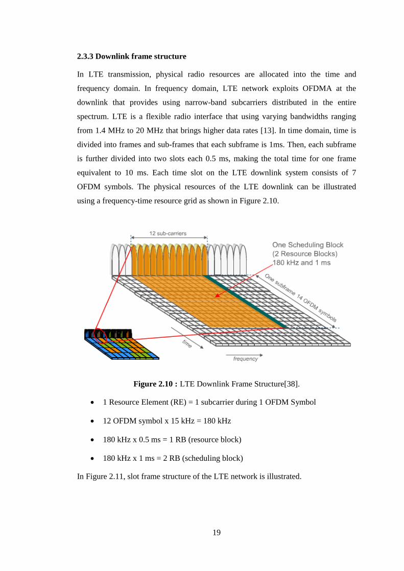
2.3.3 Downlink frame structure
In LTE transmission, physical radio resources are allocated into the time and
frequency domain. In frequency domain, LTE network exploits OFDMA at the
downlink that provides using narrow-band subcarriers distributed in the entire
spectrum. LTE is a flexible radio interface that using varying bandwidths ranging
from 1.4 MHz to 20 MHz that brings higher data rates [13]. In time domain, time is
divided into frames and sub-frames that each subframe is 1ms. Then, each subframe
is further divided into two slots each 0.5 ms, making the total time for one frame
equivalent to 10 ms. Each time slot on the LTE downlink system consists of 7
OFDM symbols. The physical resources of the LTE downlink can be illustrated
using a frequency-time resource grid as shown in Figure 2.10.
Figure 2.10 : LTE Downlink Frame Structure[38].
1 Resource Element (RE) = 1 subcarrier during 1 OFDM Symbol
12 OFDM symbol x 15 kHz = 180 kHz
180 kHz x 0.5 ms = 1 RB (resource block)
180 kHz x 1 ms = 2 RB (scheduling block)
In Figure 2.11, slot frame structure of the LTE network is illustrated.

20
Figure 2.11 : LTE Frame - Slot Structure[14].
In LTE network, a resource block (RB), which is the minimum resource unit
assigned to User Equipment (UE), corresponds to the bandwidth of 180kHz in
frequency domain and 0.5ms in time domain [13]. In this context, scheduler becomes
the key element which located at the base station and it assigns the resource block to
the terminals.The scheduler determines for each 1 ms sub-frame which user(s) are
allowed to transmit and on which resources are allocated.
In order to maintain orthogonality of the subcarriers, the guard period is generated as
a cyclic prefix (CP), by repeating some samples from the end of each symbol at the
beginning [15] as shown in Figure 2.12.
Figure 2.12 : Guard Period Cycle Prefix.
According to chosen bandwidth from 1.4Mhz to 20MHz, number of available RB is
varied from 6 to 100 respectively. It is straightforward to see that each RB has 84
resource elements in the case of normal cyclic prefix and 72 resource elements in the
case of extended cyclic prefix [13].

21
2.3.4 Resource allocation
In the scheduling process, the selection of the Modulation and Coding Schemes
(MCS) is a key issue. In LTE downlink Adaptive Modulation and Coding (AMC)
technique is used to select an appropriate MCS level for UE’s transmission according
to user channel state or condition [19].
Firstly, the UE estimates the instantaneous channel condition to determine Channel
Quality Indicator (CQI) index. Then, UE sends this CQI report as a feedback to the
eNodeB. Consequently, the eNodeB uses this CQI index to choose a certain level of
MCS and allocates resource block pairs accordingly to the UE. The relationship
between CQI index and the MCS is shown in Table 2.3, where larger CQI indices
represent higher MCS levels. Moreover, the table demonstrates more efficient usage
of channel resources and fewer resource block pairs occupied for transmission.
Table 2.3 : Mapping of CQI values versus MCS.
CQI
Index Modulation
Code
Rate x
1024
Efficiency CQI
Index Modulation
Code
Rate x
1024
Efficiency
0 Out of range 8 16QAM 490 1.914
1 QPSK 78 0.152 9 16QAM 616 2.406
2 QPSK 120 0.234 10 16QAM 466 2.730
3 QPSK 193 0.377 11 64QAM 567 3.322
4 QPSK 308 0.602 12 64QAM 666 3.902
5 QPSK 449 0.877 13 64QAM 772 4.523
6 QPSK 602 1.176 14 64QAM 873 5.115
7 16QAM 378 1.477 15 64QAM 948 5.554
However, differences in modulation and coding rates produces different Block Error
rate (BLER) performances. The relationship between Signal to Noise Ration (SNR)
and BLER curves of each CQI index were studied extensively in the literature [19]
indicating clearly that CQI is a reflection of channel quality as SNR, where a high
CQI reflects good channel condition, under which a high level of MCS could be
selected to achieve high bit rate and efficiency [20].
Figure 2.13 represents the main resource allocation modules that interact with the
downlink packet scheduler.

22
Figure 2.13 : Simplified Model of Resource Allocation[21].
The entire process shown in Figure 2.13 is repeated in every every TTI. The initial
step each UE decodes the reference signals, computes the CQI. Therby, UE sends
this CQI information as feedback to the eNodeB. Secondly, the eNodeB uses the CQI
information for the allocation decisions. Thereafter, the AMC module selects the best
MCS. These information about these users which are the allocation of RBs and the
selection of MCS are sent to the UEs on the Physical Downlink Control Channel
(PDCCH). Then each UE reads the PDCCH payload and, in case it has been
scheduled, accesses to the proper Physical Downlink Shared Channel (PDSCH)
payload [21].

23
3. SCHEDULING ALGORITHMS
In LTE networks, a dynamic scheduling is a key process to provide efficient usage of
limited resources with the lowest cost. A resource block (RB), which is the minimum
unit assigned to terminals, corresponds to the bandwidth of 180kHz in frequency
domain and 0.5ms in time domain. For the downlink direction, if the bandwidth is 20
MHz, there are 100 RBs available in the system. When there are 50 active users,
there are 10050
different RB to UE assignments. This huge possibility shows the
scheduler importance and ability. Especially for highly loaded networks, scheduler
can significantly affect the system performance.
We also know that the key characteristic of the mobile radio communication is rapid
and significant changes in the channel conditions due to shadowing, fast fading,
multipath, etc. These instantaneous and random variations affect the quality of each
radio channel in a cell. Therefore, the changes in channels should be taken into
account when scheduling is performed. Thus, our objective in this thesis is to
propose a novel scheduler to maximize the network performance.
Scheduling controls the allocation of shared resources among the users at each time
constant. In LTE, for each Transmission Time Interval (TTI) of 1 ms, the scheduler
determines which user(s) are allowed to transmit and which resources are allocated.
After scheduling, scheduling map will be sent to all terminals. Individual terminal
only decodes received data in certain particular time and frequency based on
scheduling map. By periodically receiving the feedback information from the
terminals, the scheduler in the base station dynamically adjusts scheduling decisions
to ensure efficient resource allocation and quality of service requirements.
Generally, scheduling can be divided into two classes: channel-independent
scheduling and channel-dependent scheduling [26]. Channel-independent scheduling
does not take channel conditions into account. On the contrary, channel-dependent
scheduling is performed by allocating resources based on channel conditions. It deals
with how to share available radio resources between different terminals to achieve
efficient resource utilization as possible. This implies to minimize the amount of

24
resources needed per user while still satisfying quality of service requirements. Thus,
as many users as possible in the system can use the resources.
Furthermore, scheduling can be classified based on application scenarios, since the
performance of scheduling algorithms highly relies on the type of incoming flows. In
order to achieve application specific performance, it is important to select suitable
algorithms according to traffic types of flows which can be divided into real-time and
non real-time by considering LTE services, including such as voice, data and video
[28].
In this chapter, existing scheduling algorithms considering traffic types and channel
qualities are explained below along with their main ideas. Followingly, Chapter 4
represents the proposed algorithms which are focus on channel-dependent
scheduling to achieve better performance in resource allocation between real-time
and nonreal-time users.
3.1 Non Real Time Scheduling Algorithms
A packet scheduler performs its allocation decision to maximize the satisfaction level
of system requirements. A scheduler measures system satisfaction based on a
desirable performance metric, such as per UE's experienced data rate, fairness in
resource allocation among UEs, average packet delay experienced by UEs, etc. The
choice of what performance metric to optimize influences how the scheduler resolves
resource contention among UEs. In general, the scheduling algorithms aim at
providing efficient resource sharing, better performance in terms of delay,
throughput, link utilization, fairness, complexity, etc. Scheduler pursues the optimal
or suboptimal solution of above functions, while considers computation overhead.
The most popular scheduling algorithms for nonreal-time flows in LTE networks are
Round Robin [25], MaxC/I [26] and Proportional Fair [29]. The performance of
nonreal-time algorithms is measured with throughput and fairness.
In the following subsection we will provide more detailed discussion on studied three
scheduler algorithms.

25
3.1.1 Round robin
Round Robin is one of the simplest resources scheduling algorithms. It is commonly
applied in operating systems and computer networks. In the beginning, terminals are
ordered randomly in a queue. The new terminals are inserted at the end of the queue.
The first terminal of this queue is assigned all the available resources by scheduler,
and then put it at the rear of the queue. The rest of step sound follow the same way,
until no terminal applies for resources. On one hand, it is a fair scheduling, since
every terminal is given the same amount of resources. On the other hand, it neglects
the fact that terminals in bad channel conditions need more resources to carry out the
same rate, so it is not absolutely fair. However, it is much fairer than Max C/I.
Although Round Robin gives every terminal equal chance to obtain resources, the
overall throughput is much lower than Max C/I, because scheduler does not consider
channel conditions.
Robin scheduling is a non-aware scheduling scheme that lets users take turns in using
the shared resources (time/RBs), without taking the instantaneous channel conditions
into account [29]. Therefore, it offers great fairness among the users in radio resource
assignment, but degrades the system throughput performance.
In LTE, different terminals have different service with different QoS requirements. It
is impossible to allow every terminal to take up the same resources in the same
possibility, because it will decrease efficiency of resources. Nevertheless, Round
Robin is a good reference to measure the fairness of scheduling for LTE.
Fig 3.1 illustrates the Round Robin, MaxC/I and Proportional Fair algorithms’
resource allocation as a ring chart flow.
Figure 3.1 : RR, Max C/I, PF Schedulers[37].

26
3.1.2 Max C/I
As the name implies, this scheduling strategy assigns RBs to the UE with the best
radio link conditions. In order to perform scheduling, the channel quality indicator
(CQI) reports are generated by the UE and fed back to the eNodeB in quantized form
periodically. Scheduler analyzes CQI values from terminals to obtain data rate of an
identical sub-channel for different terminals. Then scheduler assigns this sub-channel
to the terminal which can achieve the highest data rate in this sub-channel based on
SNR. A higher CQI value means better channel condition. Based on the CQI
received, the best CQI is selected for scheduling. The following equation describes
the Max C/I that Rk,n (t) represens data rate of terminal k for one sub-channel n in
time slot t (3.1).
)(maxarg , tRi nkk
(3.1)
As a channel dependant scheduling, Max C/I takes advantage of multiuser diversity
to carry out maximum system throughput[28]. However, terminals in bad channel
conditions are never considered by this scheduler algorithm that causes starving
terminals while having best channel terminals obtain maximum throughput.
Therefore, this scheduler is not a fair algorithm. Nevertheless, it can be considered as
a good reference to distribute resources among terminals while they realy acquire
maxcimum throughput rates. In this thesis, Max C/I is used as mainly reference
scheduler algorithm to allocate resource blocks to the users.
3.1.3 Proportional fair
Proportional Fair is a compromise between Maximum Rate and Round Robin [29]. It
pursues the maximum rate, and meanwhile assure that none of terminals is starving.
The terminals are ranked according to the priority function. Then scheduler assigns
resources to terminal with highest priority. These steps are executed recursively until
all the resources are used up or all the resources requirements of terminals are
satisfied.
The following equation describes the priority function that Rk,n (m) represens the
estimation of the supported data rate of terminal k for resource block n where Rk (m)
shows the average data rate of terminal k over a windows in the past (3.2).

27
)(
)(maxarg
,
mR
mRi
k
nk
k
(3.2)
The update of the Rk in this scheduler can be specified in two ways. One of them is
that Rk is updated when all resource blocks are allocated. The other one is that Rk is
updated after each resource block allocation. (3.3) is the equation to present Rk
update where T shows the windows size of the average throughput if the user k is
selected. In our simulation environment, PF scheduler takes the second update
prosedure during allocation.
)(1
)()1
1()1( , mRT
mRT
mR nkkk (3.3)
The PF provides a good trade off between system utility and fairness by selecting the
user with highest instantaneous data rate relative to its average data rate [28], [29].
The PF was designed specifically for the BE service class and hence does not
guarantee any QoS requirement such as delay, jitter and latency.
In the literature, many approaches are proposed to define fairness parameter; one of
the most outstanding parameter is Ray Jain’s fairness index [27]. Thus, in this thesis
Jain’s fairness index, (3.4) is used to measure fairness among users in the system.
K
k
K
k
kTK
kT
TJ
1
2
2
1
)(
))((
)( (3.4)
It is a throughput and number of UEs based equation where K is the total number of
users and ̅ is a vector representation of user equipments’ current throughput values.
The fairness index changes between zero and one. When whole users have the same
throughput in the system, the fairness index becomes one that it is the ideal fairness
scenario.

28
3.2 Real Time Scheduling Algorithms
Real-time flows have more delay sensitive than nonreal-time flows. Therefore the
scheduling algorithms are differentiated resulting in the reduction of influence of
error correction.
In wireless communication, RT flows can be modeled as arrival process of
independent packets to respective queues, under a delay target constraint. For
different wireless network models, there are several stabilizing policies to satisfy
different delay target constraints [28]. For example, the stabilizing policy of system
whose delay target is the maximum delay deadline is to make sure that the length of
queues is in a certain bound.
The most popular scheduling algorithms for RT flows are Largest Delay First,
Modified Largest Weighted Delay First. The main performance metrics are firstly
delay experience then packet loss rate and fairness for RT purpose.
3.2.1 Largest delay first
This scheduler is very similar to the Round Robin algorithm for NRT flows. It
neglects the channel condition and when the first package is received by base station,
it will be sent out in the first place. According to equation (3.5), Dk is the time that
package of terminal k has spent at the base station waiting for scheduling.
)(maxarg mDi kk
(3.5)
However, because of this scheduler first in first out characteristic property, result
becomes with poor throughput.
3.2.2 Modified largest weighted delay first
Modified Largest Weighted Delay First Algorithm is designed to balance the delay
of the packects to use the channel resources efficiently. The M-LWDF resource
allocation algorithm is tailored to support multimedia services, considering that this
scheduler outperforms other state-of-the-art schedulers in supporting video streaming
services [30].

29
This scheduler mainly relies on the delay of the packets: the packets that violate the
target delay of the service while waiting at the MAC buffer will be discarded.
However, NRT services are scheduled using the classical PF rule. The MLWDF was
designed to meet QoS requirements and has been proved to be throughput-optimal in
[31]. A scheduling rule is termed throughput optimal if it satisfies the rule that it
renders the queues to be stable.
(3.6) describes the priority function of the MLWDF scheduler where Rk (m) shows
the average data rate of terminal k, Dk is the delay of the first packet to be
transmitted in the queue and αk is the maximum probability that the packet delay
exceeds the target delay.
)(
)(*)(*maxarg
,
mR
mRmDi
k
nk
kkk
(3.6)
Although this thesis has not had enough resource to extend our algorithms to
compare these algorithm results, MLWDF are studied here to prepare for the future
work in Section 6.
3.3 Mixture of Real Time and Non Real Time Scheduling Algorithms
In realistic networks RT and NRT traffics are flowing together and both of them are
considered with mixture real-time and nonreal-time scheduling algorithms. The most
popular scheduling algorithms for mixture of real-time and nonreal-time flows are
Exponential Rule, Virtual Token Modified Largest Weighted Delay First. The QoS
performance parameters are measured by throughput, delay experience and fairness.
3.3.1 Exponential proportional fair
It is important to ensure that a proper trade-off is maintained between fairness,
throughput-optimality and delay requirements for a scheduling algorithm to be truly
efficient. The Exponential Rule algorithm is designed to achieve this goal. The
intuition is to increase the weight of the far away users on slight improvement in
their channel conditions while keeping the weight of the users near by
proportionately less since they would get very good data rates due to their
proximityis designed to balance the delay of the packects to use the channel
resources efficiently [30]. The exponential rule is given by (3.7), (3.8), (3.9):

30
aW
WtWtRi kk
kkk 1
)(exp)(maxarg
(3.7)
k kk tW
NW )(
1 (3.8)
)(tRk
kk
(3.9)
Rk (t) shows estimation of supported data rate of terminal k in time slot t. )(tRk is the
average data rate of terminal k. k is the priority coefficient which reflects the
desired QoS of terminal k. W(t) is the longest time that terminal k’s packets are spent
on base station. When the differences in the waiting times are very small, a small
change in the waiting time is reflected as a large change in the exponent value due to
which, the rule behaves like the PF algorithm.
3.3.2 Virtual token modified largest weighted delay first
Virtual Token Modified Largest Weighted Delay First Algorithm is designed to
balance the delay of the packects to use the channel resources efficiently. The virtual
token resource allocation algorithm,VT-M-LWDF, focuses on RT services whereas a
minimum throughput has been guaranteed for NRT services [31].
This scheduler is mainly based on the queue size of each RT flow‘s buffer, as this
helps allocate most of the resources to video flows first, whereas NRT services are
penalized. The virtual token scheme is a modification of the M-LWDF rule that VT-
M-LWDF scheduler takes into consideration, in addition to the earlier parameters,
the queue size parameter of each RT flow‘s buffer. This provides the scheduler an
indication about the significance of the flow available in the buffer. Conversely, the
M-LWDF scheduling decision is made with regard mainly to the packet delays.
The main goal of the VT-M-LWDF rule is to improve the QoS performance metrics
for multimedia services, such as video and VoIP, and to maintain minimum
throughput guarantee for NRT services. Furthermore, the latter impacts on the QoS
requirements that belong to NRT services. Hence, there is a trade-off in the delivery

31
of the QoS requirements between the RT and the NRT services. The following
equation (3.10) illustrates the metric used to represent the VT-M-LWDF scheduler:
)(
)(*)(*)(
,
,mR
mRmQmW
k
nk
kknk (3.10)
Qk(m) refers to the queue size of the k-th flow at a particular scheduling epoch (m)
when serving RT users. On the contrary, the PF scheduler is selected to make
scheduling decisions when serving NRT users.

32

33
4. PROPOSED SCHEDULING ALGORITHMS
The task of a scheduler in an LTE base station is to allocate available physical
resource blocks to the users. This allocation process is carried out within evolved
NodeB (eNodeB) in the LTE network architecture. An eNodeB includes the
functionalities of both Base Station Controller (BSC) and Radio Network Controller
(RNC) which were two distinct entities in the traditional cellular network
architecture. Radio resource allocation task, which distributes available radio
resources to UEs, is carried out within eNodeB. None of the existing standard
scheduling algorithms such as Round Robin, MaxC/I and Proportional Fair takes
channel qualities and traffic types into account at the same time when the available
resources are allocated to UEs. For example, MaxCQI scheduler allocates Resource
Blocks (RBs) to UEs solely using Channel Quality Indicator (CQI) information
without taking the QoS requirements of UEs into account. These schedulers also do
not provide any instrument to influence the scheduling operation according to
changing network conditions. Similarly, recent studies on the QoS-aware LTE
schedulers can be found in Section 1.2 Literature Review part.
Self-Organizing Network (SON) is a type of network which optimizes the system
parameters both at the deployment phase (planning stage) and also with respect to
changing network conditions during run-time (e.g., changes in traffic demand,
wireless link qualities, user locations, etc.). A SON feature for the LTE network can
be realized in two steps:
(i) extending the existing LTE scheduling algorithms to make them
reconfigurable to varying network conditions
(ii) reconfiguration of the LTE scheduling parameters when network
conditions changes.
In this thesis, three LTE downlink scheduling algorithms, taking both channel
qualities and traffic types of UEs into account, are proposed to realize the first step of
the SON feature. A reconfigurable parameter in the proposed schedulers determines

34
the resource prioritization level for real-time services, and hence allows network
administrators to more effectively control the resource allocation according to the
QoS requirements such as throughput, packet loss, delay and fairness of UEs and
changing network dynamics.
Figure 4.1 demonstrates a high level design of our scheduling algorithm. First,
incoming traffic is classified into real-time and nonreal-time flows. Active UEs,
which need a resource block, are inserted into a priority list. The priorities are
determined using traffic type and channel quality information of UEs. For example,
real-time traffic has strict priority over nonreal-time traffic in one variant of the
proposed scheduling algorithms. Finally, the scheduler assigns available resource
blocks to the users according to the order in the priority list.
Identify Traffic Type
UDP TCP
List
Scheduling
Figure 4.1 : Scheduling Algorithm Flow Chart.
The pseudo code of the first variant of our proposed scheduling algorithm
(Algorithm_1) is shown below. The incoming traffic user is inserted to the priority
list by using traffic type (real-time or nonreal-time) and channel quality information.
In this version, all real-time flows have higher priority than nonreal-time flows and
hence the traffic type is the most important factor to determine the insertion point of
the incoming traffic in to the priority list.

35
Algorithm_1: Strict Priority based RB allocation for real-time traffic
N = Number of UEs;
CQI_i = Channel Quality Indicator for UE i;
T_i = Traffic Type for UE i;
RB = Available Resource Block;
L = Priority List for RB Allocation;
initialize L to empty
for i=1 to N
if (T_i == UDP)
add UE i to upper part of L,
insertion point to L is determined by CQI_i
else if (T_i == TCP)
add UE i to lower part of L,
insertion point to L is determined by CQI_i
allocate RBs to UEs according to the order in L
It is conjectured that Algoritm_1 maximizes the performance of real-time traffic by
providing higher throughput, lower loss rates, and lower end-to-end delays while the
performance of nonreal-time traffic significantly degrades.
Algorithm_2: RB allocation with reconfigurable traffic prioritization
N = Number of UEs;
CQI_i = Channel Quality Indicator for UE i;
T_i = Traffic Type for UE i;
RB = Available Resource Block;
L = Priority List for RB Allocation;
X = Percentage of nonreal-time users whose priorities are made equal to real-time
users;
initialize L to empty
for i=1 to N
if (T_i == UDP)
add UE i to upper part of L,
insertion point to L is determined by CQI_i
else if (T_i == TCP)
add UE i to lower part of L,
insertion point to L is determined by CQI_i
move X% of TCP flows to upper part of L,
insertion point to L is determined by CQI values
allocate RBs to UEs according to the order in L
The pseudocode of the second variant of our proposed scheduler algorithm,
Algorithm_2, is shown above. This is an improved version of Algorithm_1 in a sense
that the network administrator can control the tradeoff between the performance

36
improvement of UDP flows and the performance degradation of TCP flows by
tuning the reconfigurable traffic prioritization parameter X. When X is set to zero,
Algorithm_2 and Algorithm_1 are the same.
Algorithm_3 : RB allocation with reconfigurable traffic prioritization
N = Number of UEs;
CQI_i = Channel Quality Indicator for UE i;
T_i = Traffic Type for UE i;
RB = Available Resource Block;
L = Priority List for RB Allocation;
X = Percentage of nonreal-time users whose priorities are made equal to real-time
users;
initialize L to empty
for i=1 to N
if (T_i == VoIP )
add UE i to upper part of L,
insertion point to L is determined by CQI_i
if (T_i == Video)
add UE i to lower part of L after VoIP users,
insertion point to L is determined by CQI_i
else if (T_i == TCP)
add UE i to lower part of L,
insertion point to L is determined by CQI_i
move X% of TCP flows to upper part of L,
insertion point to L is determined by CQI values
allocate RBs to UEs according to the order in L
From the result of real-time and nonreal-time flow algorithms, Algorithm_3 is
formed to serve multi traffic scenario including the administrative control aspect.
This algorithm can also handle multi real-time traffics (VoIP and Video) with the
reconfigurable performance parameter X.
The pseudocode of our proposed scheduler Algorithm_3 is shown above.
Additionally, Algorithm_3 has advantages both supporting the multi-traffic scneraio
and treating the real-time and nonreal-time traffic according to specified QoS
parameters. With the help of this administrative operation, although the origin of the
existing algorithms are only designed for nonreal-time traffics, Algorithm_3 can
handle both real-time and nonreal-time traffic and even multi-traffic.
In this instance, proposed algorithm takes a crucial role to balance real-time traffic to
gain better performance results internally while controlling the nonreal-time as well.
In order to attain QoS for VoIP traffic, VoIP users are evaluated at the top of the

37
priority list. Video streaming and the users has nonreal-time traffic, FTP, can be
operated by the network administrater by using traffic type and channel quality
information. It means, number of non real-time users with higher CQI values can be
moved to planned area to be assessed in real-time traffic by prioritization parameter
X. The tradeoff between the performance advantage of the UDP flows and the
disadvantage of the TCP flows still exist, however the parameter X turns the
undesired conditions to positive way if it is used in the right place in the right time.
It denotes that X parameter is an adjustable parameter that can fullfill the expectation
of network requirements.
Quality of Service (QoS) refers to the capability of a network to guarantee a certain
level of performance to a selected traffic flow using various technologies [32].
In LTE networks, quality of service is measured quantitatively by related
performance measures of each network service such as throughput, packet loss,
delay, jitter, and fairness.
Throughput measurement in LTE downlink depends on the amount of information
transferred from a server to a user equipment within a certain time. For example, for
the file transfer application, the throughput is calculated by dividing the transferred
file size (bits) to the download duration (seconds) to get the throughput in bits per
second. When the users share the same network resources; due to dynamic changes
in network conditions, throughput for real-time services may not be sufficient if all
data streams get the same scheduling priority.
End to end delay is another criteria to fullfill QoS requirements of each traffic flow
because it might take a long time to reach its destination. The average end to end
delay in second is calculated by dividing the sum of end to end delay of all the
received packets to the number of received packet. The lost packets are excluded in
the average end-to-end delay calculation.
The network performance of a user is often measured not only in terms of delay, but
also in terms of the packet loss which is measured as the percentage of the number of
received packets to the number of the total sent packets. A lost packet is
retransmitted for TCP traffic to ensure that all the TCP data are reliably transferred
from source to destination.

38
A fair distribution of system resources among different users is another important
QoS parameter. There are several mathematical definitions of fairness. Our fairness
measurement depends on the Jain’s fairness index. Equation 3.4 shows the
calculation where the fairness index changes between zero and one. When all the
users have the same throughput, the fairness index becomes one that indicates the
ideal fairness scenario.

39
5. SIMULATION RESULTS
In this section, the simulation environments of the proposed algorithms are explained
and simulation results are shown followingly. A brief description of the simulation
tool OMNeT++ is also included in the simulation environment part.
5.1 Simulation Environment
5.1.1 Simulation tool OMNeT++
OMNeT++ is an open source discrete event simulator which is especially designed to
support simulation of network systems. It is mostly useful to build and represent
hierarchical structures that are frequently used in design environment. The platform
of this simulator is mainly implemented using the C++ programming language. Also,
since OMNeT++ uses GCC tool chain or the Microsoft Visual C++ compiler, it can
be executed in three most common platforms: Windows, OS X, Linux [33].
OMNeT++ can be operated freely for non-profit use and provides a powerful and
consistent open-source library that can easily be used by research-oriented
institutions. It is mainly used in research fields especially in communication
networks area. Another advantage of this tool is different model structures can be
implemented in OMNeT++ environment although these models are built outside of
the OMNeT++ platform. Moreover, specific models and frameworks such as
VANET [32] and INET [34] and can be used to extend the functionality provided by
OMNeT++ platform.
OMNeT++ is designed to simplify the simulation of network systems [35]. It
provides visualization and customization with its integrated development
environment (IDE) [39]. OMNeT++ IDE contains multiple source code editors
related to different activities. Also, IDE provides single environment to gather
multiple structures in a single compound and compile them into a single unit. What is
more, network component modification can be completed without coding by
OMNeT++ IDE tool. The simulation environment is shown in Figure 5.1.

40
Figure 5.1 : OMNeT++ Simulation Environment Example.
OMNeT++ simulation tool has two kinds of user interfaces. They are TKENV and
CMDENV interfaces. TKENV is OMNeT++'s GUI as shown in Figure 5.2.
Figure 5.2 : OMNeT++ Simulator GUI.
It is built up to show automatic animation, module output windows and object
inspectors. Automatic animation in OMNeT++ is capable of animating the owner of
messages on network charts. Module output windows make it possible to open
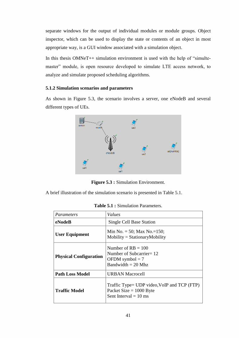
41
separate windows for the output of individual modules or module groups. Object
inspector, which can be used to display the state or contents of an object in most
appropriate way, is a GUI window associated with a simulation object.
In this thesis OMNeT++ simulation environment is used with the help of “simulte-
master” module, is open resource developed to simulate LTE access network, to
analyze and simulate proposed scheduling algorithms.
5.1.2 Simulation scenarios and parameters
As shown in Figure 5.3, the scenario involves a server, one eNodeB and several
different types of UEs.
Figure 5.3 : Simulation Environment.
A brief illustration of the simulation scenario is presented in Table 5.1.
Table 5.1 : Simulation Parameters.
Parameters Values
eNodeB Single Cell Base Station
User Equipment Min No. = 50; Max No.=150;
Mobility = StationaryMobility
Physical Configuration
Number of RB = 100
Number of Subcarrier= 12
OFDM symbol = 7
Bandwidth = 20 Mhz
Path Loss Model URBAN Macrocell
Traffic Model
Traffic Type= UDP video,VoIP and TCP (FTP)
Packet Size = 1000 Byte
Sent Interval = 10 ms

42
As can be seen Table 5.1, simulation parameters are demonstrated. SISO (Single
Input Single Output) system with Single Cell configuration is used during
simulations. While UDP traffic is represented downloading video from server and
VoIP communication, TCP traffic is designed for FTP users. Mobility of the users is
chosen as Stationary Mobility in 20Mhz bandwith that provides 100 available
resource blocks to allocate between mobile users.
For each proposed algorithm simulation environment uses the same simulation
paramaters. The test condition is performed by changing number of RT and NRT
users.
5.2 Simulation Results of Algorithms
5.2.1 Algorithm_1 and Algorithm_2
In the first set of experiments, the performances of Algorithm_1 and MaxC/I are
compared by varying the number of UEs from 60 to 150 shown in Figure 5.4. For all
experiments, 80% of total users have only real-time traffic (UDP) while 20% of total
users have only nonreal-time traffic (TCP). It means, for example 120 UEs with real-
time traffic, 30 UEs with nonreal-time traffic for 150 UEs.
Figure 5.4 : Packet Loss of RT traffic (UDP).
In the second set of experiments, the number of UEs is set to 150 and the effects of
the traffic prioritization parameter on the performances of real-time and nonreal-time
users are analyzed by varying X between 10% and 40%. In other words, the
0
5
10
15
20
25
30
35
40
60 70 80 90 100 110 120 130 140 150
Pac
ket
Loss
(%
)
Users
Real-time (UDP)
Algorithm_1 MAXC/I

43
simulations of Algorithm_2 are realized only with 150 users by changing the
percentage of TCP traffic which is given higher priority. This scenario is particularly
selected to demonstrate the effects of the reconfigurable traffic prioritization
mechanism. Since there are only 100 RBs, radio resources are not sufficient to
support 150 UEs.
Figure 5.4 demonstrates the packet loss percentages for real-time (UDP) traffic as the
number of UEs varies from 60 to 150. Each UDP flow has constant bit rate traffic
(packet size of 1000 bytes and send interval of 10 ms). The amount of traffic injected
to the network increases when the number of UEs increases. Since the number of
resource blocks is limited to 100, the packet loss rates are very low when the number
of UEs is less than 100 for both algorithms. Algorithm_1 provides higher priority to
the real-time flows when the resource blocks are allocated to UEs, and hence the
average packet loss rates are lower compared to MaxC/I when the number of UEs is
higher than or equal to 100. Followingly, Figure 5.5 presents the throughput results
for nonreal-time (TCP) traffic.
Figure 5.5 : Packet Loss of NRT traffic (TCP).
Since Algorithm_1 provides strict priority to real-time flows, throughput values for
nonreal-time traffic become negligible when the number of UEs is beyond 80.
However, MaxC/I always provides certain throughput values irrespective of how
many UEs are in the system.
0
0,5
1
1,5
2
2,5
3
60 70 80 90 100 110 120 130 140 150
Thro
ugh
pu
t (M
bp
s)
Users
Nonreal-time (TCP)
Algorithm_1 MAXC/I

44
Figure 5.6 and Figure 5.7 show throughput values for real-time traffic and average
packet loss rates for real-time traffic, respectively, when Algorithm_2 is used. The x-
axis represents the percentage of nonreal-time traffic users whose priorities are made
equal to real-time traffic users (the parameter X in Algorithm_2, where X% of
nonreal-time flows are moved towards the top of the scheduling list). For these
experiments, the number of UEs is set to 150. The numerical values in Figure 5.6 and
Figure 5.7 are used for MaxC/I and Algorithm_1 as reference (the results do not
depend on X).
Figure 5.6 : Throughput of NRT traffic (TCP).
Figure 5.7 : Packet Loss of RT traffic (UDP).
0
0,5
1
1,5
2
2,5
3
3,5
10 20 30 35 40
Thro
ugh
pu
t (M
bp
s)
Percentage of carried TCP Users
Nonreal-time (TCP)
MAXC/I Algorithm_2
28
29
30
31
32
33
34
35
36
10 20 30 35 40
Pac
ket
Loss
(%
)
Percentage of carried TCP Users
Real-time (UDP)
Algorithm_1 MAXC/I Algorithm_2

45
As depicted in Figure 5.6, when the value of X increases, the throughput values of
nonreal-time traffic increase. However, these improvements reflect performance
degradations in the average packet loss rates for the real-time users as shown in
Figure 5.7. These results demonstrate that the tradeoff between the performance
improvement of UDP flows and the performance degradation of TCP flows can be
controlled by tuning the reconfigurable traffic prioritization parameter X of the
proposed scheduling algorithm. Accordingly, Figure 5.8 shows fairness results for
nonreal-time traffic where 5.9 displays the fairness of the real-time traffic.
Figure 5.8 : Fairness of NRT traffic (UDP).
Figure 5.9 : Fairness of RT traffic (UDP).
0
0,05
0,1
0,15
0,2
0,25
0,3
0,35
0,4
0,45
10 20 30 35 40
Fair
ne
ss
Percentage of carried TCP Users
Nonreal-time (TCP)
MAXC/I Algorithm_2
0,59
0,6
0,61
0,62
0,63
0,64
0,65
10 20 30 35 40
Fair
ne
ss
Percentage of carried TCP Users
Real-time (UDP)
Algorithm_1 MAXC/I Algorithm_2

46
The simulation results confirmed that when the parameter X increases, Algorithm_2
yields more fair results for nonreal-time traffic. Conversely, real-time traffic fairness
is affected by this tradeoff that after the 20% it drops eventually.
5.2.2 Algorithm_3
In this set of experiments, the performances of Algorithm_3 is compared with
MaxC/I and PF by varying the number of UEs from 60 to 150. For all experiments,
80% of total users have only real-time traffic (UDP) that are %40 VoIP traffic and
%40 video streaming while 20% of total users have only nonreal-time traffic (TCP).
It means, for example 40 UEs with real-time VoIP traffic, 40 UEs with real-time
video streaming traffic, 20 UEs with nonreal-time FTP traffic for 100 UEs.
The delay performance of the algorithms MaxC/I and PF are illustrated in Figure
5.10 and 5.11 in terms of VoIP and video traffic users among growing number of
users from 50 to 150. Besides, 5.12 represents VoIP packetloss results.
Figure 5.10 : VoIP Delay for MaxC/I and PF.
Delay distribution of the VoIP is achieved until the network loaded with 110 users.
Neverthless, delay rate increases dramatically as it reaches the 150 users. In addition,
video delay of the existing algorithms rises remarkably especially the network is
used by 150 users.
0
0,001
0,002
0,003
0,004
0,005
0,006
0,007
50 60 70 80 90 100 110 120 130 140 150
(s)
Users (%40 VoIP %40 Video %20 TCP )
VoIP Delay
MAXC/I PF

47
Figure 5.11 : Video Delay MaxC/I and PF.
Figure 5.12 : VoIP Packet Loss for MaxC/I and PF.
Fig 5.12 shows the percentage of VoIP packetloss with respect ro MaxC/I and PF
algorithms by changing number of users in ascending order between 50 and 150. The
user diversity makes sense when the number of users exceeds 90. That point states
the threshold where saturation of the number of available resource blocks starts. It
can be seen from the graph that less than 90 users, MaxC/I perform better whereas
PF algorithm works with lower packetloss above 90. Besides, after the user 130 the
gap of packetloss between the algorithms are increased.
0
0,1
0,2
0,3
0,4
0,5
0,6
0,7
50 60 70 80 90 100 110 120 130 140 150
(s)
Users (%40 VoIP %40 Video %20 TCP )
Video Delay
MAXC/I PF
0
0,01
0,02
0,03
0,04
0,05
0,06
0,07
0,08
50 60 70 80 90 100 110 120 130 140 150
Pac
ketl
oss
(%)
Users (%40 VoIP %40 Video %20 TCP )
VoIP Packetloss
MAXC/I PF

48
In Figure 5.13, it is evident that TCP packetloss among the users are distributed in
favor of PF algorithm with lower percentages of packetloss. Conversely, MaxC/I
packetloss is greater than PF for each network load condition.
Figure 5.13 : TCP (FTP) Packetloss for MaxC/I and PF.
Figure 5.14 indicates the real-time traffic throughput with respect to MaxC/I and PF
algorithms between 50 to 150 number of users.It is inevitable from the figure that
real-time throughput increases with the growing number of users.
Figure 5.14 : UDP (VoIP,Video) Throughput for MaxC/I and PF.
47,6
47,8
48
48,2
48,4
48,6
48,8
50 60 70 80 90 100 110 120 130 140 150
Pac
ketl
oss
(%)
Users (%40 VoIP %40 Video %20 TCP )
TCP Packetloss
MAXC/I PF
0
10
20
30
40
50
60
70
50 60 70 80 90 100 110 120 130 140 150
(Mb
ps)
Users (%40 VoIP %40 Video %20 TCP )
UDP Throughput
MAXC/I PF

49
Figures 5.15 illustrate the throughput performance of the real-time and nonreal-time
traffic according to MaxC/I and PF algorithms. As it is expected throughput rates are
increasing as a result of increasing amount of user.
Figure 5.15 : TCP (FTP) Throughput for MaxC/I and PF.
Figure 5.16, 5.17 demonstrates the delay performance of the proposed algorithm,
Algorithm_3, according to MaxC/I and PF algorithms. Vertical values show how
many nonreal-time users are moved to realtime part of the list.
Figure 5.16 : VoIP delay for MaxC/I,PF and Algorithm_3.
This percentile method is used to define some thresholds in order to fulfill the QoS
requirements between real-time and nonreal-time traffics. It can be concluded from
0
1
2
3
4
5
6
7
8
50 60 70 80 90 100 110 120 130 140 150
(Mb
ps)
Users (%40 VoIP %40 Video %20 TCP )
TCP Throughput
MAXC/I PF
0
0,001
0,002
0,003
0,004
0,005
0,006
0,007
5 10 15 20 25 30 40
(sn
)
User (%40 VoIP %40 Video %20 TCP)
VoIP delay - 150 UE
MAXC/I Algorithm_3 PF

50
the graphs that proposed algorithm can achieve the average delay for VoIP even
much better than MaxC/I algorithm. However, video delay is going up dramatically
after 20% in an unfavorable way when it is compared to MaxC/I. On the other hand,
this delay does not exceed the values of PF algorithm even for 40%.
Figure 5.17 : Video delay for MaxC/I,PF and Algorithm_3.
Moreover, it can be seen from the charts that PF algorithm succeeds in minimize the
VoIP delay where MAXC/I perform well for Video delay. Reconfigurable parameter
is required to accomplish the quality service by Algorithm_3. Consequently, Figure
5.18, 5.19, 5.20 indicate TCP, Video and VoIP throughput results respectively.
Figure 5.18 : TCP Throughput for MaxC/I,PF and Algorithm_3.
0
0,01
0,02
0,03
0,04
0,05
0,06
0,07
0,08
0,09
5 10 15 20 25 30 40
(sn
)
User (%40 VoIP %40 Video %20 TCP)
Video delay - 150 UE
MAXC/I Algorithm_3 PF
0
1
2
3
4
5
6
7
8
5 10 15 20 25 30 40
(Mb
ps)
User (%40 VoIP %40 Video %20 TCP)
TCP throughput - 150 UE
MAXC/I Algorithm_3 PF

51
It can be obtain from the results that TCP throughput value is growing because
percentage of the nonreal-time user increases relatively in the candidate list.
Algorithm_3 supports the stability between MAXC/I and PF algorithms until it
reaches the 40%.
Figure 5.19 : Video Throughput for MaxC/I,PF and Algorithm_3.
Figure 5.20 : VoIP Throughput for MaxC/I,PF and Algorithm_3.
Video throughput and delay graphs 5.19, 5.17 state the tradeoff the prioritization of
nonreal-time users. Since MAXC/I and PF algorithms firstly consider the VoIP
traffic users, Algorithm_3 move VoIP users at the top of the list that gives an
advantage to keep performance expectation between PF and MAXC/I, Fig 5.20.
39,5
40
40,5
41
41,5
42
42,5
43
5 10 15 20 25 30 40
(Mb
ps)
User (%40 VoIP %40 Video %20 TCP)
Video Throughput- 150 UE
MAXC/I Algorithm_3 PF
0,6
0,61
0,62
0,63
0,64
0,65
0,66
0,67
5 10 15 20 25 30 40
(Mb
ps)
User (%40 VoIP %40 Video %20 TCP)
VoIP throughput - 150 UE
MAXC/I Algorithm_3 PF

52
On the other hand, the tradeoff between delay and throughput can be observed
especially after 20%. When the percentage of moving nonreal-time users is
increased, TCP throughput values of them increase as well. Especially after 20%
throughput is rising significantly. However, these improvements reflect the average
packet loss ratio in real-time users. The average packet loss ratio in real-time traffic
is going up dramatically after %20 in an unfavorable way when it is compared to
MAXC/I,Fig 5.21. Moreover, delay and throughput results of video traffic are
affected in that vein, Fig 5.17, 5,19.
Figure 5.21 : UDP Packet Loss for MaxC/I,PF and Algorithm_3.
The graph of 5.22, 5.23 point out the fairness advantage of the proposed algorithm.
Figure 5.22 : TCP Fairness for MaxC/I,PF and Algorithm_3.
0
0,2
0,4
0,6
0,8
1
1,2
1,4
5 10 15 20 25 30 40
Pac
ketl
oss
(%
)
User (%40 VoIP %40 Video %20 TCP)
UDP Packetloss - 150 UE
MAXC/I Algorithm_3 PF
0
0,1
0,2
0,3
0,4
0,5
5 10 15 20 25 30 40
Fair
nes
s In
dex
User (%40 VoIP %40 Video %20 TCP)
TCP Fairness - 150 UE
MAXC/I Algorithm_3 PF

53
Although TCP fairness increase with respect to increasing number of TCP users,
UDP traffic fairness can be maintained within reasonable interval between MAXC/I
and PF algorithms.
Figure 5.23 : UDP Fairness for MaxC/I,PF and Algorithm_3.
The fairness index parameter depicted in 5.22 and Figure 5.23 are illustrated to show
TCP and UDP flows, respectively. This parameter shows how the system is serving
users fairly by assigning a fair share of system resources. Hence, the figures show
that the proposed scheduler achieves better fairness for different types of services.
0,705
0,71
0,715
0,72
0,725
0,73
0,735
0,74
0,745
0,75
5 10 15 20 25 30 40
Fair
nes
s In
dex
User (%40 VoIP %40 Video %20 TCP)
UDP Fairness - 150 UE
MAXC/I Algorithm_3 PF

54

55
6. CONCLUSION AND FUTURE WORK
The main reason behind the world’s switching to LTE technology is to fullfill
growing number of mobile user necessities such as higher end-user data transfer
rates, lower latency for real-time services with lower cost of operation. Compared to
previous networks, LTE introduces as a flexible radio interface to provide
interopabilitiy of heterogenous networks, flexible bandwidth usage and support end
to end IP based services. To objective these specifications LTE scheduler is the key
enabler to ensure QoS requirements by maximizing the usage of limited resources.
In LTE; scheduling, radio resource allocation task, is carried out within eNodeB
instead of controllers such as BSC or RNC in the traditional cellular network
architecture. In this context, channel-dependent scheduling has a crucial role by
allocating resources based on channel conditions. It performs how to share available
radio resources between different terminals to achieve efficient resource utilization
as possible. By periodically receiving the feedback information from the terminals,
the scheduler in the base station dynamically adjusts scheduling decisions to
maximize resource allocation and meet quality of service requirements.
In this thesis; QoS-aware reconfigurable scheduling algorithms which provide higher
priority to the real-time users are proposed using channel-dependent scheduling.
None of the existing scheduling algorithms such as Round Robin, MaxC/I and
Proportional Fair do not take both the traffic types and channel qualities into account
and there is no service guarantee for real-time traffic. However, our proposed
scheduler takes both channel qualities and the traffic types into consideration and
reconfigurable parameter gives an opportunity to the administrator to control the
tradeoff between the performance of real-time and non-real-time traffic.
The main idea of the our algorithms is to meet the delay requirements of real-time
traffic first and then maximize the performance of nonreal-time users in terms of
their throughput, average packet loss ratio and fairness. Algorithms are appiled to
minimize the amount of resources needed per user while still satisfying the QoS. In
this regards, three scheduler algorithms are studied that from first to third, the

56
algorithms are extended to reach more realistic results. First, incoming traffic is
classified into real-time and nonreal-time flows which are inserted into a priority list
according to traffic types and channel qualities. Algorithm_1 mainly consider the
taking traffic types into accout that classifies real-time and nonreal-time traffics to
prioritize real-time flows. The scheduler assigns available resource blocks to user
equipments (UEs) using the order in the list. Algorithm_2 focuses on reconfigurable
parameter that gives a control to the network administrator between real-time and
nonreal-time flows for efficient resource allocation. A reconfigurable parameter in
the proposed scheduler determines the resource prioritization level for real-time
services, and hence allows network administrators to more effectively control the
resource allocation according to the QoS requirements of UEs and changing network
dynamics. Algorithm_3 which is the extended version of Algorithm_2, considers
both channel qualities and multi-traffic types of terminals into account to support
QoS requirements the user perceived. Moreover, a reconfigurable parameter is
included to achieve the resource prioritization level for real-time services, and hence
allows network administrators to more effectively control the resource allocation
according to the QoS requirements of users and changing network dynamics. In this
way, by considering channel qualities and traffic types to support QoS and minimize
human involvement in network operation with reconfigurable parameter satisfies the
self-organizing network requirements.
OMNeT++ based simulation results demonstrate that the tradeoff between the
performance improvement of real-time flows and the performance degradation of
nonreal-time flows can be controlled by tuning the reconfigurable traffic
prioritization parameter of the proposed scheduling algorithm with multiple traffic
scenarios.
For the future work, scenarios and simulation environment can be extended to
support more realistic network dynamics (e.g., multiple base stations, realistic traffic
scenarios including more traffic classes). To add, users with various mobility patterns
will be introduced. Furhermore, the proposed algorithm can be extended to run
autonomously without human in the loop by receiving certain performance results
(e.g., delay, packet loss, etc.) as feedback from the terminals instantanously.
Moreover, autonomous operation of the scheduling will decrease the operational cost
substantially and enable an important SON feature in LTE networks.

57
REFERENCES
[1] Dahlman, E., Parkvall, S., Skold, J., Beming, P., “3G Evaluation HSPA and
LTE for Mobile Broadband”, pp. 277-537. Elsevier Edition, Oxford,
2008
[2] Sachs, J., Prytz, M., and Gebert, J., “Multi-access Management in
Heterogeneous Networks”, Wireless Personal Communications, Vol.
48, No. 1, pp.7-32, 2007
[3] Peng, M., Liang, D., Wei, Y., and Li, J., Chen, H., “Self-Configuration and
Self-Optimization in LTE-Advanced Heterogeneous Networks” IEEE
Communications Magazine, May 2013
[4] Nasralla, M., and Martini, M. G., “A Downlink Scheduling Approach for
Balancing QoS in LTE Wireless Networks”, IEEE 24th International
Symposium on Personal, Indoor and Mobile Radio Communications:
MAC and Cross-Layer Design Track, 2013
[5] Muller, K. M., Schwarz, S. and Rupp, M., “QoS Investigation of Proportional
Fair Scheduling in LTE Networks”, Wireless Days (WD), IFIP, 2013
[6] Shang, P., Zeng, Y., Wu, J., Xiao, P., “A Novel Resource Scheduling Algorithm
to Improve TCP Performance for 3GPP LTE Systems” Wireless
Communications and Networking Conference (WCNC), 2013
[7] de Moraes, T.M., Saleh, A.B., Bauch, G., Seidel, E., QoS-Aware Traffic
Scheduling in LTE-Advanced Relay-Enhanced Networks”, IEEE 77th
Vehicular Technology Conference (VTC Spring), 2013
[8] Lin, G. Y., Lai, W. K., Yang K., Lin M., “An Novel Scheduling Algorithm for
Video Stream in LTE”, Sixth International Conference on Genetic and
Evolutionary Computing, 2012
[9] Wu, S., Chio, L., “A Novel Packet Scheduling Scheme for Downlink LTE
System”, Seventh International Conference on Intelligent Information
Hiding and Multimedia Signal Processing, 2011
[10] Khan, N., Martini, M., G., Bharucha, Z., “Quality-aware Fair Downlink
Scheduling for Scalable Video Transmission over LTE Systems”
IEEE 13th International Workshop on Signal Processing Advances in
Wireless Communications (SPAWC), pp. 264-269, 2012
[11] Chandur., P., Karthik R. M., and Sivalingam, M., Performance Evaluation of
Scheduling Algorithms for Mobile WiMAX Networks, IEEE PerCom
Workshop on Pervasive Wireless Networking 2012

58
[12] Astély, D., Dahlman, E., Furuskär, A., Jading, Y., Lindström, M., Parkvall,
S., “LTE: The Evolution of Mobile Broadband”, IEEE
Communications Magazine, April 2009
[13] Dahlman, E., Furuskär, A., Jading, Y., Lindström, M. and Parkvall, S., Key
features of the LTE radio interface,” Ericsson Review, no. 2, pp. 77–
80, 2008.
[14] Dahlman, E., Parkvall, S., Skold, J., “4G LTE/LTE Advanced for Mobile
Broadband”, pp. 143-335, Academic Press, 2011
[15] Le, K., "Major Trends in Cellular Networks and Corresponding Optimization
Issues," Wireless Network Design: Optimization Models and Solution
Procedures, Springer Science, 2011
[16] Glisic, S. G., “Advanced Wireless Networks 4G Technologies”, Wiley, 2006,
pp. 101-658
[17] Song, L., Shen, J., “Evolved Cellular Network Planning and Optimization for
UMTS and LTE ”, CRC Press, 2011, pp. 399-487
[18] Fares, S. A., and Adachi F., “Mobile and Wireless Communications Physical
Layer Development and Implementations”, 2010, pp. 190-208
[19] Iturralde, M., Yahiya, T.A., Wei, A., and Beylot, A., “Resource Allocation
Using Shapley Value in LTE Networks”, Personal Indoor and Mobile
Radio Communications (PIMRC), 2011 IEEE 22nd International
Symposium
[20] Gemici, Ö.F, Hokelek, İ., Çırpan H.K., “Trade-off Analysis of QoS-Aware
Configurable LTE Downlink Schedulers” on Telecommunications
(ICT), International Conference, 2013
[21] Capozzi, F., Piro, G., Grieco, L.A., Boggia, G., and Camarda, P., “Downlink
Packet Scheduling in LTE Cellular Networks: Key Design Issues and
a Survey”, IEEE Communications Surveys & Tutorials, Vol. 15, No.
2, Second Quarter 2013
[22] Maier, G., Schneider, F. and Feldmann, A., “A First Look at Mobile Hand-
Held Device Traffic,” Lecture Notes in Computer Science, Vol. 6032,
2010
[23] Johansson K., “Cost Effective Deployment Strategies for Heterogeneous
Wireless Networks”, Ph.D. Thesis, KTH, Stockholm, 2007
[24] Karvounas, D., Vlacheas, P., Georgakopoulos, A., Tsagkaris, K.,
Stavroulaki, V., Demestichas, P., “An Opportunistic Approach for
Coverage and Capacity Optimization in Self-Organizing Network”,
Future Network & MobileSummit 2013 Conference Proceedings, Paul
Cunningham and Miriam Cunningham (Eds), IIMC International
Information Management Corporation
[25] AlQahtani, S.A., Alhassany, M., “Comparing Different LTE Scheduling
Schemes”, Wireless Communications and Mobile Computing
Conference (IWCMC), 2013 9th International

59
[26] Habaebi, M. H., Chebil, J., Al-sakkaf, T. H., Comparison Between Scheduling
Techniques In Long Term Evolution Dahawi IIUM Engineering
Journal, Vol. 14, No. 1, 2013
[27] Jain, R., Chiu, D., Hawe, W., “A Quantitative Measure of Fairness and
Discrimination for Resource Allocation in Shared Computer
Systems,” Tech. Rep. TR-301, DEC, September 1984
[28] Alfayly, A., Mkwawa, I. H., Sun, L., “QoE-based Performance Evaluation of
Scheduling Algorithms over LTE”, IEEE GC'12 Workshop: Quality
of Experience for Multimedia Communications, 2012
[29] Kawser, M.M.T., Farid, H.M.A.B., Hasin, A.R., Sadik, M.J., and Razu,
I.K., “Performance Comparison between Round Robin and
Proportional Fair Scheduling Methods for LTE”, International Journal
of Information and Electronics Engineering, Vol. 2, No. 5, September
2012
[30] Wu, S., Chu, L., “A Novel Packet Scheduling Scheme for Downlink LTE
System”, Seventh International Conference on Intelligent Information
Hiding and Multimedia Signal Processing, 2011
[31] Khan, N., and Martini, M.G., “Quality-aware Fair Downlink Scheduling for
Scalable Video Transmission over LTE Systems”, IEEE International
Workshop on Signal Processing Advances in Wireless
Communications (SPAWC), 2012
[32] Kuo, J., Shih, C., and Chen, Y., “Performance analysis of real-time streaming
under TCP and UDP in VANET via OMNET”, International
Communications on ITS Telecomunications,ITST, 2013
[33] Martonalti, B.,“NEPTSim : Simulating NEPTUNE Canada using OMNeT++ ”,
University of Victoria, Master Thesis, 2012
[34] Kellerbauer, H., Hirsch, H., “Simulation of Powerline Communication with
OMNeT++ and INET-Framework”, IEEE International Symposium
on Pwerline Communications and Its Applications, 2011
[35] Andreozzi, M. M., “LTE and LTE-Advanced evaluation through innovative
simulation tool”, IEEE International Symposium, World of Wireless,
Mobile and Multimedia Networks (WoWMoM), 2011
[36]Url-1<http://www.3gpp.org/technologies/keywords-acronyms/98-lte>,date
retrieved 10.01.2014.
[37] Url-3 < http://internal.ericsson.com>, date retrieved 23.03.2014.
[38] Url-2 <https://github.com/inet-framework/simulte>, date retrieved 12.04.2014.

60

61
APPENDICES
APPENDIX A: VoIP – Streaming – FTP
VOIP:
VOIP stands for ‘Voice Over Internet Protocol’ and implies multimedia
communication over Internet Protocol. Voice is digitized, compressed and
packetized, and is sent over IP network in this technology. Thus, it is fully packet-
switched technology. Codecs are used to encode voice. Some popular codecs are
G.711, G.722, G.729, AMR etc. In 3GPP, Adaptive Multi Rate (AMR) wideband
and narrowband codes are used. Different codes have different encoding rate. For
example, G.711 converts voice into 64 Kbps stream, while G.729 converts voice into
8 Kbps stream VoIP uses Session Initiation Protocol (SIP) or H.323 as signaling
protocol to initiate and terminate the connection between voip users. Generally,
VOIP services use User Datagram Protocol (UDP) as datagram protocol as these
services are delay-sensitive. UDP does not guarantee the delivery of the packets as
there is no retransmission scheme. However, this is simple, faster and efficient
scheme. Real-time Transport Protocol (RTP) is data transfer protocol which deals
with the transfer of real-time data. RTP is used to maintain Quality of Service (QoS).
RTP works only on UDP. VOIP traffic consists of talk-spurts and silent periods. One
VOIP packet arrives every 20 msec during talk-spurts, while one Silence Indicator
(SID) packet arrives every 160 msec during silent period that VOIP is peer-to-peer
technology. Skype is an example of VOIP application.

62
Streaming:
Streaming generally means the process of sending digitized video and audio packets
over internet so that the end user can watch video or hear audio in real-time fashion.
With this technology, end-user can play file (video, audio) before entire file is
downloaded. Unlike VOIP, streaming supports multicast technology, that is, many
users can watch/hear the single stream simultaneously. The generally used audio
codec in this application is MP3, while H.264 and MPEG-4 are used as video codec
Session Description Protocol (SDP) is used as signaling protocol used in describing
multimedia sessions like session initiation, session invitation, etc. Other protocols
used in this application are RTP, RTP Control Protocol (RTCP), Hyper Text Transfer
Protocol (HTTP), and Real-time Streaming Protocol (RTSP). RTCP is a control
protocol and works in conjunction with RTP. RTSP is application-level protocol
used in transferring real-time data. RTSP allows user to play the downloaded and
decompressed packets, while it continues downloading and decompressing next
arrived packets in parallel. Thus, it enables end-user to use real-time data. Streaming
takes help from another application-layer protocol HTTP as well. To begin
streaming, user has to go to web-page. The web-page then directs to RTSP server.

63
FTP:
FTP is an application-layer based protocol which allows users to transfer files
between two computers over IP network. It supports Transmission Control Protocol
(TCP) only as transport layer protocol. TCP is connection oriented transport layer
protocol which takes consideration of retransmission for error control, and thus
guarantees successful delivery of data. TCP also supports flow control, that is,
window size to transfer data is already negotiated between sender and user. This
scheme ensures that user gets data only at that data-rate that it supports. FTP works
with server and client approach. When client sends a file-transfer request to server,
TCP connection is established. TCP then segments the data and put unique
identification to each segment. For each segment, client and server do
communications with acknowledgements. If any segment is lost or corrupted, that
segment is retransmitted. Some commercial software such as ‘FileZilla’, ‘CoreFTP’
can be used as FTP client and server. In this project, TI built-in FTP client has been
used.

64

65
CURRICULUM VITAE
Name Surname: Beste Akkuzu
Place and Date of Birth: IZMIR / 21.04.1989
Address: Emniyetevler Mah. 4.Levent / Istanbul
E-Mail: [email protected]
B.Sc.: Electronics and Communication Engineering / IYTE
Professional Experience and Rewards: Highest Ranked Student, B.Sc.
List of Publications and Patents:
PUBLICATIONS/PRESENTATIONS ON THE THESIS
H.Anil Akyildiz, Beste Akkuzu, İbrahim Hökelek, Hakan Ali Çırpan, Servis
Kalitesine Duyarlı Yeniden Yapılandırılabilir LTE MAC çizelgeleyici. IEEE Sinyal
İşleme ve Uygulamaları (SIU) Kurultayı, April 23-25, 2014 Trabzon, Turkey
H.Anil Akyildiz, Beste Akkuzu, İbrahim Hökelek, Hakan Ali Çırpan, QoS-Aware
Reconfigurable LTE MAC Scheduler, IEEE International BlackSea Conference on
Communications and Networking, May 27-30, 2014 Odessa, Ukrain.