istr evolus rel-1-6 cd0500gb x prisma-cdr10 · general safety warnings thoroughly read this manual...
TRANSCRIPT

Operator
for sliding
automatic doors
EVOLUS - GB - Rel.1.6 - 05/2010 - CD0500GB
IGB
INS
TA
LLA
TIO
N M
AN
UA
LIN
STA
LLA
TIO
N M
AN
UA
L EVOLUSEVOLUS
TRANSLATION OF ORIGINAL INSTRUCTIONS

GENERAL SAFETY WARNINGS page 3
MAINTENANCE PROGRAM 3
1 - TYPICAL PLANT 4
2 - AUTOMATED EQUIPMENT DESCRIPTION 4
3 - COVERING CASING 8
4 - ADJUSTMENT OF THE BELT TENSIONING 9
5 - POSITIONING THE MECHANICAL LIMIT SWITCH 9
6 - ANCHORING THE LEAVES TO THE CARRIAGES AND ADJUSTING THEM 10
7 - INSTALLATION MEASURES 11
8 - SLIM ELECTRIC LOCK 14
9 - ELECTRONIC CONTROL UNIT 21
10 - ELECTRIC CONNECTION DESCRIPTION 22
11 - PRJ38 PHOTOCELLS 25
12 - BATTERY-OPERATED OPENING DEVICE EV-BAT1 26
13 - FUNCTIONAL TESTING “INITIAL SET-UP” 26
14 - S1 DIP-SWITCH FUNCTIONS 27
15 - S2 DIP-SWITCH FUNCTIONS 28
16 - CONTROL UNIT POTENTIOMETER ADJUSTMENT 29
17 - WORK PROGRAM SELECTION DEVICES 3017a) - EV-MSEL MECHANICAL KEY SELECTOR 3017b) - EV-DSEL DIGITAL PROGRAMMER 31
18 - “UR1” MODULE 39
19 - DESCRIPTION OF FUNCTIONS SELECTABLE FROM EV-DSEL DIGITAL PROGRAMMER (F01 to F40) 39
20 - DESCRIPTION OF POTENTIOMETERS ADJUSTABLE FROM EV-DSEL DIGITAL PROGRAMMER (P01 to P35) 43
21 - INTERLOCKING SYSTEM BETWEEN TWO AUTOMATIC DOORS 46
22 - DOOR CROSSING WARNING GONG 48
23 - SENSOR TEST 49
24 - MEANING OF BUZZER WARNING SIGNALS (BIPs) 49
25 - PROBLEMS, CAUSES AND REMEDIES 50
DECLARATION OF CONFORMITY 51
TABLE OF CONTENTS:
EVOLUS

GENERAL SAFETY WARNINGS
Thoroughly read this manual before starting installation.Both the mechanical and the electric systems must be installed in compliance with the code of practice and with the regulations in force.Failure to comply with them may result in injuries or damages.The person in charge of installing the product must be skilled and properly qualified; he must make sure that the structure to be automatised is stable and robust, and if necessary make the required structural changes.He must also check that all areas involving any danger of crushing, conveying, shearing, etc are protected by means of electronic safety devices, safety freeboards or safety fences.These devices must be installed in compliance with the regulations in force and with the code of practice, also taking into account the usage environment, the usage type and the product operation logic.Forces generated by the whole system during operation must comply with the regulations in force; should it turn out to be impossible, involved areas must be protected by electronic safety devices.Dangerous areas must be signalled in accordance with the provisions of the regulations in force.Before connecting the product make sure that the mains features are compatible with the technical data indicated in this manual and that upstream of the system there are a suitable residual current device and a suitable overcurrent protection device.Remember to cut off the power supply before opening the machine cover, when performing any maintenance or installation operation.Electrostatic charges may damage electronic components on boards; use grounded antistatic bracelets if you must perform any operation on electronic boards.Don't insert your hands or other parts of your body into moving components like belts, pulleys, carriages, etc...Product maintenance is essential for system operation and safety;The periodical check of the efficiency of all parts should be carried out every 6 months.The manufacturer accepts no responsibility for incorrect product installation and usage, as well as for any damages arising from changes to the system made without his prior consent. Only genuine spare parts must be used for product component replacement and repair.The manufacturer is not responsible for the construction of the fixtures to be automated, nor for any damages arising from failure to observe the code of practice in fixture construction.The IP22 protection degree requires that automated equipment is installed only on the inner side of buildings.The manufacturer accepts no responsibility for any damages caused by outdoor installation without suitable protection measures.Before installing the product always check its integrity.This product cannot be installed in explosive environment and atmosphere, or in the presence of flammable gases or fumes.At the end of its life this product must be disposed of in accordance with the regulations in force.Keep product and packaging materials out of children's reach, as they might be a source of danger.Do not stay within the range of the door and do not impede the door movement voluntarily.Do not let the children stay or play within the range of the door.
3
Every 6 months:
Warning! Before performing any operation on the automated equipment cut off the main power supply.- Check that all screws are tight.- Check the belt's tension.- Clean the carriage sliding rail and the ground sliding guide. - Check that carriages and leaves are properly aligned and that the door's final ledge is in correct position.- Check that the electric lock - if any - is properly fastened and that the mechanical release device operates properly. - Check connections and electric cables- Check leaf stability and make sure that they move smoothly and frictionless along the whole stroke.- Check that motion speeds, involved forces and installed safety devices are working appropriately.- Clean sensors and check that presence detectors activate properly.
Warning! Any damaged or worn system component must be replaced.
Make use only of original spare parts; for this purpose check Label price list.
MAINTENANCE PROGRAM

4
2 - AUTOMATED EQUIPMENT DESCRIPTION
MODEL
Power supply
Power
Maximum weight of door wings
Electric motor
Opening speed
Closing speed
Pause time
Working temperature
Degree of protection
Power supply of external accessories
Transom dimensions (H x P.)
Transom length
EVOLUS-90/2
40Vdc with encoder
Max. 70 cm/s (per leaf)
Max. 60 cm/s (per leaf)
Max. 20 sec.
-20° C +50°C
IP22
13 Vdc
120 x 150 mm
max 6500 mm
÷
115/230V ac +/- 10% , 50-60Hz
80W 130W
90 Kg 130 Kg 150 Kg 200 Kg
1 - TYPICAL PLANT
2.1 - TECHNICAL SPECIFICATIONS
4
6
FT
=2x0.2
5
x 54 0.
4
FR
=3x0.2
5
2x0.5
4x0.5
2x0.5
FT
=2x0.2
5
FR
=3x0.2
5
44
3 2
1a
4x0.5
3x1.5
mm
EXTERNAL RADAR FOR OPENING
START BUTTON
PROGRAM SELECTOR
SAFETY SENSORS FOR OPENING
CLOSING SAFETY CELLS PRJ38 (FT = transmitting photocell, FR = receiving photocell)
EVOLUS AUTOMATED EQUIPMENT
1a
2
3
4
5
1b
6
7
KEY SELECTOR FOR EMERGENCY OPENING
OUTER SIDE INNER SIDE
7
5
51b
Notes: The grey part identifies the radar and sensor detection area. For each device the picture indicates the number of cables and the relevant section in millimetres.
EVOLUS-90/1 EVOLUS-130/2 EVOLUS-130/1
4 0.5x
4.5x0
INTERNAL RADAR FOR OPENING

2.2 - PART DESCRIPTION
5
12
13
14
17
16
12
transom
clip
sliding rail
casing
casing compensating profile
rail gasket
brush
13
14
15
16
17
15
18
18
2
1
3
4
side panel pair
electronic control unit
motor assembly with encoder
cover links
double wheel carriage5 10
6
7
8
9
l
upper belt coupling
ower belt coupling
cable gland
idle pulley
mechanical limit switch
driving belt
21
345678
9
10
1
10
4
11
11

2.3 - COMPONENT ARRANGEMENT
DOUBLE DOOR LEAF WITHOUT ELECTRIC LOCK
LT LT=2PL-B+2S+24
BEAM LENGTH PL FREE PASSAGEPL=(LT+B)/2-S-6
LM LM=(LT-B)/4+S/2-6
LEAF WIDTH F LT*3/4+75
IDLE PULLEY M MOTOR400mm
C CONTROL UNIT345mm
S S
BLM LM
PL
LT
SINGLE LEAF RH WITHOUT ELECTRIC LOCK
LT BEAM LENGTHLT=2PL-B+S+24
PL FREE PASSAGEPL=(LT+B-S)/2-12
LM LEAF WIDTHLM=(LT-B+S)/2-12
F IDLE PULLEYLT-87
M MOTORLT-LM-342
C CONTROL UNITLT-LM-397
S
LT
PL
B
LM
FM
C
FM
C
SINGLE LEAF LH WITHOUT ELECTRIC LOCK
S
LT
PL
B
LM
MC
F
LT BEAM LENGTHLT=2PL-B+S+24
PL FREE PASSAGEPL=(LT+B-S)/2-12
LM LEAF WIDTHLM=(LT-B+S)/2-12
F IDLE PULLEYLT-87
M MOTORLT-LM-342
C CONTROL UNITLT-LM-397
6

SINGLE LEAF LH
WITH SLIM ELECTRIC LOCK
SINGLE LEAF RH
WITH SLIM ELECTRIC LOCK
LT BEAM LENGTHLT=2PL-B+S+24
PL FREE PASSAGEPL=(LT+B-S)/2-12
LM LEAF WIDTHLM=(LT-B+S)/2-12
F IDLE PULLEYLT-212
M MOTORLT-LM-467
C CONTROL UNITLT-LM-522
E ELECTRIC LOCKLT-62
DOUBLE DOOR LEAF WITH SLIM ELECTRIC LOCK
E ELETTROBLOCCO
LT BEAM LENGTHLT=2PL-B+2S+24
PL FREE PASSAGEPL=(LT+B)/2-S-6
LM LEAF WIDTHLM=(LT-B)/4+S/2-6
F IDLE PULLEYT*3/4+100
M MOTOR400mm
C CONTROL UNIT345mm
E ELECTRIC LOCKT/2 + 5mm
S S
BLM LM
PL
LT
LT BEAM LENGTHLT=2PL-B+S+24
PL FREE PASSAGEPL=(LT+B-S)/2-12
LM LEAF WIDTHLM=(LT-B+S)/2-12
F IDLE PULLEYLT-87
M MOTORLT-LM-342
C CONTROL UNITLT-LM-397
E ELECTRIC LOCK75
7
FE
MC
S
LT
PL
B
LM
E
FM
C
MC
E
F
S
LT
PL
B
LM

3 - COVERING CASING
The casing of the EVOLUS automated equipment features two support links (A) specially designed to ensure that it remains stable in the opening position.
A
To fully remove the casing from the automated equipment press the end section of the pins (B) located on the support links and extract them by pulling them from the opposite end (Fig. 1)Manually support the casing before extracting the pin.In the lower section of the casing there is a compensating profile allowing to close the gap between the fixture and the casing, thus improving the automated equipment appearance.To adjust the compensating profile depth you must detach the casing from the automated equipment and put it on a flat surface FIG. 3.Arrange the compensating profile as shown in the figure and fasten it to the casing by means of the special clips.
Choose the optimum adjustment depth for the compensating profile referring to Fig. 4 then fasten each plastic clip by first inserting the clip teeth into the compensating profile grooves and then pushing the upper section of the clip forward until it connects to the casing.Put the casing back in place on the automated equipment by reinstalling the support links with the special pins, then close the casing over the automated equipment hooking the upper section to the transom FIG. 5.
Fasten the casing by means of the screws located on side panels FIG. 6.
If the beam is flush with the wall you can fasten the casing frontally, by drilling a hole at the front seat on the side panel and fastening the casing by means of the special EV-KFCF Kit (optional) FIG. 7.
SIDE PANEL SIDE VIEW
SIDE PANEL FRONT VIEW
A
FIG.1
FIG.2
FIG.5
FIG.3
FIG.6
FIG.7
B
8
X
FIG.4
Number of meshing teeth X dimension
8
7
6
5
4
3
66,8
62,7
58,5
54,4
50,2
46,1

4 - ADJUSTMENT OF THE BELT TENSIONING
To adjust belt tensioning slightly loosen the A screw of the idle pulley, then screw in (to increase belt tensioning) or unscrew (to decrease belt tensioning) the hexagonal screw B.After achieving the optimum driving belt tension fully tighten screw A.
A B
5 - POSITIONING THE MECHANICAL LIMIT SWITCH
The mechanical limit switch must be adjusted so that both during opening and closing it stops the carriage stroke before the mobile leaf crashes against any other component.It is also used by the electronic control unit to acquire the leaf limit points.When adjusting the opening mechanical limit switch take into account that except for the set-up manoeuvre and for the first manoeuvre after a power failure, at the end of the opening the movable leaf stops about 5 mm before coming into contact with the limit switch.To adjust the limit switch loosen the 2 fastening screws, move the limit switch to the desired position, then fully tighten the 2 screws again.
FASTENING SCREWS
9
FIG.8
FIG.9

10
46100
156
46100
156
65
120
175
65
120
175
FIG.11
6 - ANCHORING THE LEAVES TO THE CARRIAGES AND ADJUSTING THEM
!
!
!
!
!
!
!
!
Undo the two front screws "A" of every carriage and remove the movable part "C".Fasten the movable part "C" you removed to the fixture at the distance indicated in figure 11 if no electric lock is installed or in figure 12 if the electric lock is installed.Now hang the leaf to the automated equipment matching the two carriage parts, then screw the "A" screws into their seats without tightening them.Adjust the height of the leaf by means of the control screw "B" and fully tighten the two "A" screws.Adjust the leaf horizontally by means of the eyelets "E" provided in the movable part of the carriage.To ensure that the automated equipment works properly it is important that the mobile leaf is perpendicular to the transom.Adjust the height of the opposing wheel by operating the adjustment screw (D) so that the wheel skims the top inner part of the transom, but without exerting any pressure.Then manually move the leaf until it reaches the end of stroke and check that there are no frictions at any point; otherwise adjust the opposing wheel position again.
D
C
E
A
BE
FIG.10
65
120
175
65
120
175
120
175
120
175
FIG.12
65 65

7 - INSTALLATION MEASURES
The transom must be fastened to a flat surface solid enough to bear the weight of the leaves to be used.If the wall or the support do not meet these characteristics you will have to provide for a suitable tubular element, as the transom is not self-bearing.Fasten the transom by means of M6 steel or equivalent anchors.The fastening points must be distributed alternately between the reference lines on the beam (L1 and L2) every 600mm.The figure shows the fastening dimensions.When drilling the beam and the wall take care not to damage the sliding rail (B1) as that would affect the operation and the noiselessness of the automated equipment.After fastening the beam thoroughly clean the sliding area from any drilling scraps.
11
150
120
27
27,6 23FIG.13
78
16
36,641,5
MAX 8mm
L1
L221,5
78
36,5B1
FIG.14
20

DIMENSIONAL TABLE FOR EVOLUS 90 AND 150 OPERATORS
1 MOBILE LEAF 2 MOBILE LEAVES
Dimensioning mm
PL= nominal passage opening
LT= automationlength
LT=2PL-B+S+24
Dimensioning mm
LM= LT-B S 4 2
+ - 6
LM= leaf S= overlapped partB=ledge withS=50 B=10
PL= LT+B 2
- - 6S
PL= nominal passage opening
LM= LT-B+S 2
- 12
LM= leaf S= overlapped partB=ledge withS=50 B=10
PL= LT+B-S 2
- 12
2000250030003500400045005000550060006500
516.5 641.5 766.5 891.51016.51141.51266.51391.51516.51641.5
949119914491699194921992449269929493199
2000250030003500400045005000550060006500
1008125815081758200822582508275830083258
968121814681718196822182468271829683218
S
LT
PL
B
LM
S S
BLM LM
PL
LT
SECTION WITH POLISHED EDGE ATTACHMENTSECTION WITH COMMERCIAL PROFILES
PAD1
P6S
PT1
150
120
2041,4
78
23
2541,5
39,1
70
50
H
13
H-1636,5
28
27
M801010
PT3
2041,4
78
2541,5
150
120
H H-19
39,1
70 H+6,5
10 38
LT=length
LT=2PL-B+2S+24
automation
LEGEND:
PL = LT = LM = H =
FREE PASSAGEAUTOMATION LENGTHLEAF WIDTHPASSAGE OPENING HEIGHT
12

REFERENCE STANDARDS
Check the presence of the clearance distances indicated by the figures.
>25_
MAXIMUM ALLOWED OPENING
<8_
<8_
>8
>8
>25_
MAXIMUM ALLOWED OPENING
>200_
MAXIMUM ALLOWED OPENING
>250
>500_
MAXIMUM ALLOWED OPENING
<250
Clearance distances for head protection.
Clearance distances for body protection.
Clearance distances for finger protection.
13
Clearance distances for finger protection.

8 - SLIM ELECTRIC LOCK
14
1) GENERAL DESCRIPTION
The EVOLUS automation electric lock is available in 3 models, which have different behaviour during a power failure.
a) “EV-EBSFSA” FAIL SAFE
In the case of a power failure, main power supply and emergency battery power, the electric lock will free the leaves, which can then be moved manually.
b) “EV-EBSFSE” FAIL SECURE
In the case of a power failure, emergency battery power, the electric lock will keep the leaves blocked.
main power supply and
c) BISTABLE “EBSBIS”
In the case of a power failure, emergency battery power, the electric lock will remain in its current position.Therefore, the leaves are free if the electric lock was not activated, or will remain blocked if the electric lock was activated.
main power supply and
2) POSITIONING and ELECTRIC CONNECTION
The dimensions for fastening the electric lock on the automation are specified in the EVOLUS Rel.1.6 Operator Installation Manual (Paragraph 2.3).The electric lock is fastened to the automation by 2 M6 X 10 screws on M6 nuts, which are located in the special lower slot in the transom.The sliding carriages must be regulated so that when the leaf is in the closed position, the electric lock lever can hook to the carriage bracket and keep the leaves blocked.
The electric lock kit includes a power supply cable. This cable has two wires on one end that are connected to the electric lock solenoid wires with the specific terminals. The other end of the cable has a connection that is inserted in the LOCK1 connector on the Evolus operator electronic control unit.If the bistable electric lock EV-EBSBIS is installed, there will be a second power cable. One end of it must be connected to the secondary solenoid cables (LOCK2) of the electric lock and the other end must be connected to the LOCK 2 output on the electronic control unit where the connector is located.
Electric locks are supplied in Kit, including coupling brackets and fastening accessories.

15
3) MANUAL RELEASE
The Fail Secure EV-EBSFSE and Bistable EV-EBSBIS models are equipped with the EV-EBSMA manual release system that is used to release the electric lock in the case of a power failure, and therefore move the leaves freely.
3a) RIGHT SIDE FASTENING
In this case, the bend pipe must be inserted inside the plastic base.
Insert the steel cable inside the bend pipe as shown in the figure.
A
B

16
Fasten the base of the release knob to the side panel using 2 self-threading screws, making the bend pipe enter the hole made in the side panel.Apply the adhesive label as shown in the figure, taking the four black bands on the label as a reference, which must be positioned in correspondence of the 4 cardinal points.Insert the steel cable terminal into the release knob as shown in the figure and fasten the knob to the base with the special screw.
SCREW COVER
LABEL
Apply the screw cover label on the fixing screw.By moving the release knob to the UNRELEASED position, only the orange part of the label must be seen with the drawn black arrows.
At this point, insert the plastic release components inside the specific slot made in the upper part of the crosspiece and check that they can slide freely in their housing without going out.
Insert the sheath and the metal cable inside the plastic component.Fasten the first plastic release component near the right side panel with 2 of the self-threading screws in the kit, which will catch in the slot of the transom.
C
D
E
F
Place the second release component at about 300mm from the centre of the electric lock and fasten it with two self-threading screws supplied in the Kit.Connect the plastic component and the electric lock using the sheath L = 250.Insert the metal cable in the plastic component and in the sheath.
G

17
H
I
L
M
Insert the compression spring and insert the metal cable inside the special release anchor, then lock it with the screw clamp.Adjust the cable tension so to give the spring a light pre-load.
Check that the manual release works, when the knob is in the locked position, the electric lock must work normally.
When the knob is in the released position, the electric lock must remain open and free the leaves.
Cut the exceeding steel cable from the release anchor.
NOTE:In case of FAIL SECURE electric lock, by releasing the release, the electric lock will close.In case of a bistable electric lock, by releasing the release, it will open.In case it is necessary to manually close the door with a bistable electric lock, it will be sufficient to lift the core of the secondary solenoid with a screwdriver.

18
N
O
P
Is even possible to install the release knob on the left side of the automation.
In this case, the adjustment register must be fastened on the base of the release knob.
Insert the steel cable inside the adjustment register and the sheath...
...and fasten the base of the release knob to the side panel using 2 self-threading screws.
3b) LEFT SIDE FASTENING
3c) ELECTRIC LOCK INSTALLATION ON SINGLE LEAF EVOLUS OPERATOR
In case of single-leaf installation, the electric lock must be installed at one end of the transom.In this case the sheath and the metal cable are inserted directly inside the electric lock without using the release plastic components.
FOLLOW THE INSTRUCTIONS FROM ITEM TO ITEM .D M

19
MAX50 cm
CABLE TERMINALCABLE BLOCKCABLE TERMINALLOWER SCREW
Pass the release cable in the slit in the base and then inside the adjustment register as shown in the figure. Then position the cable terminal on the release knob cable block (see figure).
Now, insert the release knob on the base of the mechanism, being careful to keep the cable terminal in the seat of the cable block and the knob in the correct position. When inserting the knob, the cable terminal must be in the position just beyond the lower fastening screw, in a clockwise direction.
Drill the wall and fasten the base of the release mechanism using the fastening screws.Apply the adhesive label as shown in the figure, taking the four black bands on the label as a reference, which must be positioned in correspondence of the 4 cardinal points.Insert the adjustment register using 2 nuts, one in the plastic slot and the other outside of it.
BLACKBANDS
BLACKBANDS
FASTENING SCREW
FASTENING SCREW
Identify the fastening point on the wall, considering that the standard cable sheath is 50 cm long.
SCREW COVER
LABEL
4) INSTALLATION OF THE MANUAL RELEASE ON THE WALL
Once the knob is inserted, fasten the closing screw, insert the sheath and turn the knob to the UNRELEASED position. In this position, only the orange part of the label must be seen with the drawn black arrows.Make sure that the system is operating by turning the knob clockwise and keeping the cable taut with your hand.
WARNING!:THE KNOB TURNS MAX 45-50 DEGREES AND AT THE END, THERE ARE CLICKS IN ORDER TO MAINTAIN THE POSITION AFTER THE RELEASE.
Apply the provided screw cover label as shown in the figure and return the knob to the UNRELEASED position.

20
Fig.A
1) Through the specific slit in the side plastic cap (Fig.A).
PLASTIC RELEASE COMPONENT
2) From the lower part of the transom using a plastic release component when there is no space on the sides of the automation (Fig.B).
Now, bring the cable inside the beam. This can be done in two ways:
Fig.B

9 - ELECTRONIC CONTROL UNIT
21
13
V STA
RT
40
VS
ET-U
P
F123
0V
ac
5A
M+ -
+13V
0
+
DIG
ITA
L
PR
OG
RA
MM
ER
MOTOR
ENCODER
EM
ER
GE
NC
Y
BA
TT
ER
Y
+1
3V
AB
J1
J3J4
J5J6
J7J8
TX PHOTOCELLS (blue)
TX1 PHOTOCELL (brown)
TX2 PHOTOCELL (brown)
TX3 PHOTOCELL (brown)
RX1 PHOTOCELL (brown)
RX2 PHOTOCELL (brown)
RX3 PHOTOCELL (brown)
RX PHOTOCELL VCC (blue)
RX PHOTOCELL GND (black)
EMERGENCY
SAFETY PHOTOCELL FOR CLOSING
COMMON
INTERNAL RADAR
EXTERNAL RADAR
START
COMMON
AUX 1
SAFETY SENSOR FOR OPENING
STOP / INTERLOCK
AUX 2
TEST for prearranged SENSORS
SENSOR POWER SUPPLY
ELECTRIC LOCK 1
ELECTRIC LOCK 2
OUTPUT 3 for UR1 MODULE
OUTPUT 4 for UR1 MODULE
OP
EN
ING
SP
EE
DC
LO
SIN
GS
PE
ED
RE
DU
CE
DO
PE
NIN
GD
ISTA
NC
E
PO
WE
RP
AU
SIN
GT
IME

CONTROL AND DISPLAY COMPONENTS
LEDSDL1 (40V) = presence of 40V voltage at the switching power supply.DL2 (13V) = presence of the 13V output voltage at terminals 17-18.DL3 (E1) - DL4 (E2) = they display the signals coming from the encoder sensor. DL5 (WD) = it displays the proper operation of the main micro-controller MP1 by blinking very fast; if the led is off or it
blinks slowly it indicates an electronic board fault.DL6 (F1) = it displays the status of photocell 1 mod. PRJ38.DL7 (F2) = it displays the status of photocell 2 mod. PRJ38.DL8 (F3) = it displays the status of photocell 3 mod. PRJ38.
Dip switch S1-S2 = they select the work functions of the control unit.TM1 to TM6 potentiometers = calibration of the control unit work parameters.Buzzer = Buzzer.MP1 = micro-controller with software version indication label.PS1 = START button. It performs door opening.PS2 = SET-UP button. It performs the initial set-up of the control unit.
· TERMINAL BOARD 1 (F-N-GROUND)
230Vac 50-60Hz mains supply; phase at terminal F, neutral at terminal N, ground at terminal
The line is protected by 5A fuse F1.
On the power supply network foresee an omni-polar switch/selector with contact opening distance at least of 3 mm.The power supply line must be protected against short circuit and dispersion to ground.Separate the 230Vac power supply line from the very-low voltage line control unit relative to control and safety accessories.
· TERMINAL BOARD M2 (Voltage selection)
If the mains voltage is 230Vac don't wire the terminal.Only if the mains voltage is 115Vac connect the terminal poles to each other.
· TERMINAL BOARD M3 (Power supply of external
accessories)
13Vdc output for power supply to accessories (radar, photocells, sensors). Max. load 400mA.17= Positive terminal +13V.
18= Negative terminal 0.The presence of the output voltage is displayed by the DL2 led.
16= TEST terminal for safety sensors prearranged with test function.(The J12 jumper on the control unit allows to select whether the test signal must be positive P or negative N. The choice depends on the type of sensor in use).
Ground the operator by connecting the ground cable from the line to the Faston connector on the aluminum beam, connect the second ground Faston on the beam to the ground terminal on the electronic control unit.
22
M2
230Vac
M1
F1 5A
+13V
0
M3
13V
TE
ST
fo
r p
rea
rra
ng
ed
SE
NS
OR
S
SE
NS
OR
PO
WE
R S
UP
PLY
10 - ELECTRIC CONNECTION DESCRIPTION
WARNING!!On the plastic side panels of the EVOLUS operator control unit (part 1 in figure in para. 2.2) there is a hole that must be broken open, through which the electric cables must be inserted.Along the upper part of the aluminium crosspiece, there are various fairleads (part 8 in the figure in para. 2.2) inside of which the cables should be run.The installer must prepare suitable fairleads on the side panel of the operator control unit for the passage of the cables and ensure wire stability inside the operator control unit prior to the start-up of the automatic door, in order to prevent any contact between the electric cables and the moving parts of the automatism.

· TERMINAL BOARD M4 (Inputs 11, 12, 13, 14, 15)
11 = Input COMMON.
12 = auxiliary AUX 1. N.O. contact serving for different functions depending on the configuration set on the control board:a) Using the mechanical key selector for the choice of the door
work program (dip 6 of S1 ON) connect terminal 12 to terminal 3 of the mechanical selector.
b) It can be used to set the "Night lock” (closed contact) or two-way traffic (open contact) function if operation with digital programmer (dip 6 of S1 OFF) is selected. In this case the door can be managed by a simple switch allowing to pass from the day function to the night lock, without using the digital programmer.In the digital programmer is present, the activation of the AUX 1 input causes the door to close and the Night lock function to activate, by-passing the digital programmer setting.
c) If INTERLOCK operation is activated between two Label automatic doors (dip 22 ON, only selectable from the digital programmer menu), the activation of the AUX1 input by-passes the interlock function (see the “Interlock system” paragraph).
13 = input of the Safety side sensor for opening; N.C. contact. The door opens at low speed if it detects an obstacle during opening
(if dip 8 of S2 is OFF). The door stops if it detects an obstacle during opening (if dip 8 of S2
is ON)..14 = STOP or INTERLOCK input. N.C. contact that can be used for two
different purposes depending on the configuration set on the control unit:a) Stop command to stop door motion.b) Interlock signal detection, preventing door opening when the
interlock function is set (dip 22 ON, only selectable from the digital programmer menu).
c) Connection of a smoke detector to force the door to close in case of smoke detection, when the F31 function is ON, function specific for fire doors.
15 = AUX 2 auxiliary. N.O. contact. Using the EV-MSEL mechanical key selector for the choice of the
door work program (dip 6 of S1 ON) connect terminal 15 to terminal 4 of the mechanical selector.
· TERMINAL BOARD M5 (Inputs 5, 6, 7, 8, 9, 10)
5 = EMERGENCY input. N.C. contact. Activation always causes the door to open, under any condition.
6 = input of the safety side PHOTOCELL for closing; N.C. contact.If during closing it detects the presence of an obstacle the door stops and reopens.If during pause it detects the presence of an obstacle the door remains open.
7 = Input COMMON.
8 = INTERNAL RADAR input. N.O. contact. Activation causes the door to open when the day functions are on,
except when the program selector is set to incoming only or to night lock.
9 = EXTERNAL RADAR input. N.O. contact. Activation causes the door to open when the day functions are on,
except when the program selector is set to outgoing only or to night lock.
10 = START input. N.O. contact. Activation causes the door to open when the day functions are on,
while it doesn't open when the program selector is set to incoming only or to night lock.When the “WINTER OPENING” work program is selected the START command fully opens the door anyway.
23
M5
EM
ER
GE
NC
Y
SA
FE
TY
PH
OT
OC
EL
L F
OR
CL
OS
ING
CO
MM
ON
INT
ER
NA
L R
AD
AR
EX
TE
RN
AL R
AD
AR
STA
RT
M4
CO
MM
ON
AU
X 1
SA
FE
TY
SE
NS
OR
FO
R O
PE
NIN
G
ST
OP
/ IN
TE
RL
OC
K
AU
X 2

· TERMINAL BOARD M6 (Receiving photocells PRJ38)
FR1 = PRJ38 1 receiving capsule signal (brown cable).
FR2 = PRJ38 2 receiving capsule signal (brown cable).
FR3 = PRJ38 3 receiving capsule signal (brown cable).
VCC = power supply positive for all receiving capsules (blue cables).
GND = power supply negative for all receiving capsules (black cables).
· TERMINAL BOARD M7 (Transmitting photocells
PRJ38)
+FT = power supply positive for all transmitting capsules (blue cables).
FT1 = PRJ38 1 transmitting capsule signal (brown cable).
FT2 = PRJ38 2 transmitting capsule signal (brown cable).
FT3 = PRJ38 3 transmitting capsule signal (brown cable).
· TERMINAL BOARD M8 (Digital programmer)
1 = 13V power supply positive to be connected to the relevant + of the digital programmer.
2 = A communication signal to be connected to the relevant A of the digital programmer.
3 = B communication signal to be connected to the relevant B of the digital programmer.
4 = GND power supply negative to be connected to the relevant - of the digital programmer.
Connect the digital programmer to the control unit through a 4-pole cable with a diameter of 0.5 mm.
·CONNECTOR J1: Battery charger board connection.
·CONNECTOR J3: Encoder wiring connection.
·CONNECTOR J4: Motor wiring connection.
·CONNECTOR J5: Electric lock 1 wiring connection (LOCK1).
·CONNECTOR J6: Electric lock 2 wiring connection (LOCK2).
·CONNECTOR J7: Optional UR1 module connection (OUT3).
·CONNECTOR J8: Optional UR1 module connection (OUT4).
24
DIGITAL
PROGRAMMER
+13V A B
M8
M7+
TX
PH
OT
OC
EL
LS
(b
lue
)
TX
1 P
HO
TO
CE
LL (
bro
wn
)
TX
2 P
HO
TO
CE
LL (
bro
wn
)
TX
3 P
HO
TO
CE
LL (
bro
wn
)
M6
RX
1 P
HO
TO
CE
LL (
bro
wn
)
RX
2 P
HO
TO
CE
LL (
bro
wn
)
RX
3 P
HO
TO
CE
LL (
bro
wn
)
RX
PH
OT
OC
EL
L V
CC
(b
lue
)
RX
PH
OT
OC
EL
L G
ND
(b
lack
)

Selecting the number of installed photocell pairsThe electronic control unit of the Evolus automatic door can manage up to 3 photocell pairs, two of which (FT1/FR1 and FT2/FR2) as safety device for closing, while the third pair (FT3/FR3) can be used in three different ways: as leave breaking sensor if a breakout device is used, (in this case the activation of the photocell immediately stops the movement of the door) as a safety device for closing, or as an opening control. You need to select the pairs of photocells used in the system on the electronic control unit; Table 1 indicates the selection method.
Photocell operation
If the PRJ38 photocells are not installed leds F1, F2, F3 on the electronic control unit are highlighted.To ensure proper operation the photocell pairs must be perfectly aligned and at the same height; that is, the FT1 transmitter must be aligned with the FR1 transmitter, and the same applies to the other pairs. The maximum distance that can be covered by a photocell pair is of 6 metres.
·Calibrate the TM6 potentiometer on the electronic board so as to cover the distance between capsules. The led associated with the photocell pair will switch from high to low lighting, indicating that the photocell is working properly.
·If the infrared beam of the photocells is interrupted the relevant led switches from low to high lighting.
11 - PRJ38 PHOTOCELLS
Distinguishing between transmitting and receiving capsules
Each pair of PRJ38 Label photocells consists of a transmitting and a receiving capsule.Transmitting capsules have a rounded shape, while the receiving ones have a squared shape in the connection cable exit section. The transmitting capsule, besides, is equipped with a 2-wire cable bearing the PRJ38-TX mark, while the receiving capsule has a 3-wire cable bearing the PRJ38-RX mark.Drill an 11.5 mm hole to fasten the capsules into the fixture.To avoid any interference due to exposure to direct sunlight we recommend that you install the receiving capsules on the side that is best protected against sun rays.For the electric connection of the photocells to the control unit please refer to the paragraph "Electric connection description".
TABLE 1
RECEIVING TRANSMITTING
Signalling of any operation faults
·The PRJ38 photocells are constantly monitored by the control unit software, to guarantee a high safety level. If an error is detected during self-testing , the control unit emits one, two or three beeps, depending on the photocell pair that generated the malfunction. To avoid locking the open automated device and guarantee safety during closing, the door closes at reduced speed until normal photocell operation is restored.
·If during normal door operation the photocell beam is interrupted by an obstacle, the door stays open and the photocell control led stays steadily on.
25
+T
X P
HO
TO
CE
LL
S (
blu
e)
TX
1 P
HO
TO
CE
LL (
bro
wn
)
TX
2 P
HO
TO
CE
LL (
bro
wn
)
TX
3 P
HO
TO
CE
LL (
bro
wn
)R
X1
PH
OT
OC
EL
L (
bro
wn
)
RX
2 P
HO
TO
CE
LL (
bro
wn
)
RX
3 P
HO
TO
CE
LL (
bro
wn
)
RX
PH
OT
OC
EL
L V
CC
(b
lue
)
RX
PH
OT
OC
EL
L G
ND
(b
lack
)
EVOLUS control unit DIP switch S2
FT3/FR3 photocell management: F3 display ledDIP 3 DIP 4OFF OFF Photocell FT3/FR3 not installedON OFF Photocell FT3/FR3 installed as leave breaking sensorOFF ON Photocell FT3/FR3 installed as safety device for closingON ON Photocell FT3/FR3 installed as opening control
FT1/FR1 photocell management: F1 display ledDIP 1 OFF Photocell FT1/FR1 not installedDIP 1 ON Photocell FT1/FR1 installed
FT2/FR2 photocell management: F2 display ledDIP 2 OFF Photocell FT2/FR2 not installedDIP 2 ON Photocell FT2/FR2 installed

Insert the battery charger board into connector J1 located on the control unit (see the figure to the side).Connect the battery paying attention to its polarity (red cable +, black cable -), referring to the two male festoons on the control unit.
The battery charger board self-checks the battery charge level and displays a green and a red led.The green led blinks while the battery is being charged, while it stays steadily on at the end of the charging stage and during holding.The red led blinks if the battery is low or damaged with and without mains voltage, while it is steadily on in case of charged battery without mains voltage.If both leds are on that means that the battery is disconnected.
! Periodically check battery efficiency! To allow recharging batteries must always be connected to the electronic control unit! The equipment must be disconnected from the power supply when removing the batteries! In case of replacement, always use genuine batteries (NiMH, 18V, 700mAh). !
! Replacement must be performed by qualified personnel.! Remove batteries from the equipment before its disposal.! Batteries contain polluting substances; therefore they must be disposed of in accordance with the provisions of local
regulations.
In the case of replacement, do not use non-rechargeable batteries.
!
After performing the mechanical installation of the automatic door and the electrical connections to the electronic control unit, you can start up the automated equipment.·Preliminary checks
- check the cleanliness of the sliding rail and of the ground guide;- check the belt's tension;- check that leaves are properly aligned and fastened to chariots;- check that the position of the limit switch mechanical stop is correct;- check that leaves move smoothly and frictionless;- check proper operation of the electric lock, if installed, and of the relevant manual release.
·Initial SET-UPThe SET-UP procedure is a mandatory operation allowing the control unit to store leaf stroke and weight, to optimise door operation.Strictly follow the next steps.a) For the EVOLUS model: if the automated equipment is single-leaf with rightward opening set dip 5 of S1 to ON; if the
automated equipment is double-leaf or single-leaf with leftward opening set dip 5 of S1 to OFF. For the EVOLUS-T model: if the automated equipment has two mobile leaves with leftward opening set dip 5 of S1 to ON, if the automated equipment has 4 mobile leaves or two mobile leaves with rightward opening set dip 5 of S1 to OFF.
b) If the automation model is EVOLUS 90 or EVOLUS-T200 set dip 9 on S2 to OFF, if the automation is EVOLUS 150 or EVOLUS-T300 set dip 9 on S2 to ON.
c) If the FAIL SAFE model electric lock is installed set dip 9 of S1 to ON; if the FAIL SECURE model electric lock is used, instead, or if no electric lock is installed, set 9 of S1 to OFF.
d) If the EV-DSEL digital programmer is installed, set dip6 of S1 to OFF, if the EV-MSEL mechanical key selector is installed, set dip6 of S1 to ON.
e) If the LABEL PRJ38 photocells are installed, set the dips 1 - 4 of S2 according to the number of photocells that are present (see paragraph 15)
f) Check that the TM4 potentiometer (thrust power) is set to a value between middle range and maximum. g) Supply power to the electronic control unit, that will emit an initial beep and a short series of close beeps to indicate that there is
no set-up in its internal memory.h) Press and hold the PS2 set-up button as long as the control unit buzzer emits the fast beeps, then release it when the control
unit emits the 4 final beeps preceding motor starting.i) The door immediately starts in closing mode and performs a slow speed opening/closing cycle that it will have to complete for
the set-up to be correct. At the end of the manoeuver a prolonged BEEP signals the set-up is over.
IMPORTANT: during set-up don't place any obstacles in the door opening area and in the radar detection field; also, don't push the door manually.
·Functional testing- Check automatic door operation by issuing a Start pulse through the PS1 button and checking leaf opening and closing.- When dip 10 of S2 is OFF you can check through the buzzer the door thrust force during motion and verify its actual intensity.
Through the TM4 potentiometer you can adjust the thrust power; take into account that a very short buzz at start only indicates proper power calibration, while multiple intermittent signals during the stroke indicate that thrust power is too low.
To disable power signalling through the buzzer set dip 10 of S2 to ON once the testing is over.- Set the desired control unit functions through dip switches S1 and S2 and adjust the door operation parameters through
potentiometers TM1 to TM6.IMPORTANT!If any of the following parameters is changed, the initial SET-UP procedure will have to be repeated: leaf stroke, leaf weight, electric lock type.To perform a new SET-UP follow the steps described at points a) to i) above.
26
SET-UP
PS2
START
PS1
12 - BATTERY-OPERATED OPENING DEVICE EV-BAT1
BATTERYCHARGER
J1
13 - FUNCTIONAL TESTING “INITIAL SET-UP”
+-
EMERGENCYBATTERY
BATTERY
+-

14 - S1 DIP-SWITCH FUNCTIONS
27
ON
S1
DIP 9 DIP 10
OFF OFF
ON OFF
OFF ON
Electric lock type selection
FAIL SECURE EV-EBSFSE (it locks the door the door if no power is supplied and the door is closed)
FAIL SAFE EV-EBSFSA (it frees the door if no power is supplied)
BISTABLE EV-EBSBIS (if power is not supplied, the electric lock remains in its current position)
Night lock program: the door closes and can be opened by inputs START and RADAR IN for an amount of time that varies between 10” and 120” (see P23 adjustment on EV-DSEL).
DIP 2 = ON
DIP 2 = OFF
DIP 1 = ON
DIP 1 = OFF Standard function: the electric lock activates when the door is closed only in the night lock program.
Bank function: the electric lock activates when the door is closed in both day and night lock programs.
Night lock program: the door closes immediately.
Battery operation: in case of mains failure in day programs the door opens and stays open. In night program the door can be opened through the Emergency input.
DIP 3 = ON
Battery operation: in case of mains failure the door keeps working with all control inputs as long as the battery can supply power.
DIP 3 = OFF
Battery monitoring: if the battery is low or damaged, the control unit emits a 1-second beep before opening the door. The beep is emitted for the first 10 manoeuvres in day programs since battery fault detection.
DIP 4 = OFF
DIP 4 = ON Battery monitoring: if the battery is low or damaged, the door opens and stays open in day programs.
DIP 6 = ON
DIP 6 = OFF
Device for the choice of the work program: EV-MSEL mechanical key selector.
Device for the choice of the work program: EV-DSEL digital programmer.
DIP 7 DIP 8
OFF OFF
ON OFF
OFF ON
Choice procedure of the manual free door program with the key mechanical selector
Standard mode of mechanical selector and manual free door off.
Manual free door enabled for "exit only" position.
Manual free door enabled for "night lock" position.
ON ON Manual free door enabled for "winter" position.
DIP 5 = ON
DIP 5 = OFF
Running direction for EVOLUS-T door: for single leaf with rightward opening.Direction of travel for EVOLUS-T doors: for two mobile leaves with opening to the left.
Running direction for EVOLUS door: for double leaf and single leaf with leftward opening.Direction of travel for EVOLUS-T doors: for four mobile leaves or two mobile leaves with opening to the right.

15 - S2 DIP-SWITCH FUNCTIONS
28
ON
S2
DIP 1 = ON
DIP 1 = OFF PRJ38 FT1/FR1 photocell: not installed.
PRJ38 FT1/FR1 photocell: installed and working as safety device for closing.
DIP 2 = ON
DIP 2 = OFF PRJ38 FT2/FR2 photocell: not installed.
PRJ38 FT2/FR2 photocell: installed and working as safety device for closing.
DIP 3 DIP 4
OFF OFF
ON OFF
OFF ON
Operating mode of the third photocell pair FT3/FR3
PRJ38 FT2/FR2 photocell: not installed.
PRJ38 FT3/FR3 photocell: nstalled and working as leaves breaking sensor.
PRJ38 FT3/FR3 photocell: installed and working as safety device for closing.
ON ON PRJ38 FT3/FR3 photocell: installed and working as opening control.
DIP 5 = ON
DIP 5 = OFF Acceleration and braking ramp: standard.
Acceleration and braking ramp: radual for very narrow and light leaves.
DIP 6 = ON
DIP 6 = OFF Test for safety sensor when opening: NOT ACTIVE.
Test for safety sensor when opening: ACTIVE (for pre-arranged sensors only). See para. 23 "Sensor test".
DIP 7 = ON
DIP 7 = OFF Test for safety sensor when closing: NOT ACTIVE.
Test for safety sensor when closing: ACTIVE (for pre-arranged sensors only). See para. 23 "Sensor test".
DIP 8 = ON
DIP 8 = OFF The activation of the safety sensor during opening slows down motion until the opening stroke ends.
The activation of the safety sensor during opening stops motion until the obstacle is removed.
It activates acoustic signalling through the buzzer related to thrust power restriction. See p. Functional testing Initial set-up.
DIP 10 = OFF
DIP 10 = ON It disables acoustic signalling through the buzzer related to thrust power restriction.
DIP 9 = ON
DIP 9 = OFF Motor management parameters: Evolus 90 or EVOLUS-T200
Motor management parameters: Evolus 150 or EVOLUS-T300

TM1 potentiometerOpening speed adjustment; Increasing the value, the opening speed is increased too. Max. 0.7m. / sec. per leaf.
TM2 potentiometerClosing speed adjustment;Increasing the value, the closing speed is increased too. Max. 0.6m. / sec. per leaf.
TM3 potentiometerWinter opening distance adjustment; Increasing the value, the winter opening distance is increased too.
TM4 potentiometerThrust power restriction;At maximum value, the maximum door thrust is obtained.
Tm5 potentiometerPausing time with open door;Permitted values range from 0 to 20”.
TM6 potentiometerAdjustment of PRJ38 photocell sensitivity. Max range 6 metres.See p. 11 “PRJ38 photocells”.
29
16 - CONTROL UNIT POTENTIOMETER ADJUSTMENT
TM1 TM2 TM3 TM4 TM5
OPENINGSPEED
CLOSINGSPEED
REDUCEDOPENINGDISTANCE
POWER PAUSINGTIME

MANUAL FREE DOOR PROGRAMThe MANUAL FREE DOOR program can be selected by means of the key mechanical selector to disable the automatic mode of the door and to permit the manual movement of the leaves.The Table shows how dips 7 and 8 of dip-switch S1 of the EVOLUS control unit can be setup for the management of the work program with the mechanical selector.
When switching from the MANUAL FREE DOOR program to an automatic program, the door starts working again with a slow opening.
Choice procedure of the manual free door program with the key mechanical selector
DIP7 of dip switch S1 of the EVOLUS control unitDIP8Standard mode of mechanical selector and manual free door offManual free door enabled for "exit only" positionManual free door enabled for "night lock" positionManual free door enabled for "winter" position
OFF OFFON OFF
OFF ON
ON ON
30
To select the EVOLUS automatic door work program you can use the mechanical key selector, or the display digital programmer.
The EV-MSEL key mechanical selector permits to setup the work program of the automatic EVOLUS door.To enable its operation set dip 6 of S1 to ON (see paragraph 14).
ELECTRIC CONNECTIONSTERMINAL 1 = connect to input 8 (INTERNAL RADAR) of the EVOLUS control unit;TERMINAL 2 = connect to input 11 (COMMON) of the EVOLUS control unit;TERMINAL 3 = connect to input 12 (AUX1 auxiliary) of the EVOLUS control unit;TERMINAL 4 = connect to input 15 (AUX2) of the EVOLUS control unit;
OPERATING MODE
TWO-WAY TRAFFIC = to open the door by means of all the control inputs
OUTGOING TRAFFIC ONLY = to exclude the incoming detection (EXTERNAL RADAR)
NIGHT LOCK = to keep the door closed, allowing its opening only by means of the EMERGENCY input
Input and turn the key of the EV-MSEL selector to select the desired function among the 5 available functions:
DOOR ALWAYS OPEN = to keep the door open.
WINTER OPENING = to get a reduction of the opening space(anyway the START command opens the door completely).
The key can be taken out of the selector when in any position in order to prevent the work program from undesired changes.
17 - WORK PROGRAM SELECTION DEVICES
17a) - MECHANICAL KEY SELECTOR
4716
80
45
80
45
52
28
66

17b) - EV-DSEL DIGITAL PROGRAMMER
1) GENERAL INFORMATION
2) ELECTRIC CONNECTIONS
The digital programmer EV-DSEL can operate only together with the electronic control unit of the EVOLUS pedestrian automatic door and is used to set the automation work program. It also makes it possible to access a programming menu used to adjust the door operating parameters.
Connect the digital programmer EV-DSEL to the electronic control unit for the EVOLUS door using a 4 pole cable with a diameter of 0.5 mm.
connect to terminal of the EVOLUS control unit.
connect to terminal of the EVOLUS control unit.
connect to terminal of the EVOLUS control unit.
connect to terminal of the EVOLUS control unit.
Terminal +13V = +13V (1)
Terminal - = GND – (4)
Terminal A = A (2) della
Terminal B = B (3)
3) AUTOMATIC DOOR WORK PROGRAMS
The door opens by activating any installed opening control. The external radar is deactivated, all other opening controls remain active.
1 2
3 4
The internal radar is deactivated, all other opening controls remain active.
The door opens and remains open permanently.
31
By pushing the central button select the automatic door work mode.Each time a button is pressed, it switches from a work program to the next one.
The various available programs are described below.
White or black ABS container, dimensions: L100xH80xD18mm
80
10018

32
5 6
7
8
9
The door is closed and the radars and Start are not active.The door may only be opened with the Emergency opening button.
The door's automatic mode is deactivated and the leaves can be moved manually.
10
11
Press the button to reduce the passage opening.
The symbol on the display indicates that the function is on.To turn off the reduced opening function, press the same button again.
REDUCED OPENING
To prevent the set function from being modified, a password can be entered that must be input every time the digital programmer is used.WARNING!When enabling the password, be careful not to forget the access combination.
To enable the password, follow the steps described below.From the work program display, press the button for 8 seconds.The programming menu will appear on the display.
Press the button until accessing CODE, which corresponds to the password section.Briefly press the ENTER button to access password selection.
The current password is requested.
Enter the default password provided by LABEL with all digital programmers.
The default LABEL password is composed of 5 characters and is A-A-A-A-A.
Press the button in correspondence of the letter "A" and an asterisk will appear on the display in the field for the first letter.
4) PASSWORD

Press the button in correspondence of the letter "A" a second time, and an asterisk will appear on the display in the field for the second letter.
1312
Press the button in correspondence of the letter "A" a third time, and an asterisk will appear on the display in the field for the third letter.
1514
Press the button in correspondence of the letter "A" a fourth time, and an asterisk will appear on the display in the field for the fourth letter.
Press the button in correspondence of the letter "A" a fifth time and a screen will appear on the display that asks whether to enable the password “ON” or disenable the password “OFF” (if the button in correspondence of OFF is pressed, you will exit password selection and return to the programming menu)
If the ON button is pressed, a screen will appear on the display where the new password is requested.Now enter the desired password, selecting a combination of 5 characters from the letters A-B-C-D.To select the letters, press the button in correspondence of the letter itself.
1716
After entering the password the first time, the combination must be repeated a second time.Enter the previous password again.
1918
If the entered password is correct, the message “PASSWORD OK!!” will appear on the display.
The system will now automatically return to the main programming menu.Press the ENTER button for 3 seconds to exit the programming menu and return to the main work programming selection screen.
33

34
20
At this point, the password will be requested each time that the work program must be changed. Simply enter the selected combination to use the digital programmer.To change the password or disenable it, repeat the previous operations.
5) LANGUAGE SELECTION
It is possible to select the preferred language for viewing the programs and functions described on the display .To select the language, follow the steps described below.
From the work program display, press the button for 8 seconds.
The programming menu will appear on the display.
Press the button until accessing the section, which corresponds to language selection.
Briefly press the ENTER button to access language selection.
Use the or button to select the desired language. The arrow to the left shows the preselected language.
Briefly press the EXIT button to return to the main programming menu.
21
22
23
Press the ENTER button for 3 seconds to exit the programming menu and return to the main work programming selection screen.

35
24
6) FUNCTIONS and SETTINGS
The digital programmer can be used to set all dip switch and potentiometer functions to select the operating mode of the automatic door.To carry out the settings, follow the steps described below.
25
From the work program display, press the button for 8 seconds.
The programming menu will appear on the display (see fig.24, to the side).
Press the button until the section that corresponds to the functions and settings is displayed and briefly press the ENTER button to access it.
WARNING!!The functions F01 to F20 correspond to two dip switches with 10 microswitches, S1 and S2, on the electronic control unit.The potentiometers P01 - P05 correspond to the potentiometers TM1 - TM5 on the electric control unit.
It is possible to select if these parameters should be set directly from the electronic control unit or from the digital programmer. The latter solution is extremely helpful if the automatism already has the casing assembled.
To carry out the settings for parameters F01 - F20 and P01 - P05 from the digital programmer, go to function F21 and set it to ON.
Parameters F22 - F40 relative to the dip switches and P06 - P35 relative to the potentiometers are set from the digital programmer independently of the status of the F21 function.
26
To set the functions relative to the dip switches, briefly press the F01 button (see paragraph 6a).
To carry out the settings relative to the potentiometers, briefly press the P01 button (see paragraph 6b).
6a) How to set the FUNCTIONS of the DIP SWITCHES
27 28
To change the status of a dip switch, press the ON button to set the dip switch to ON .
To return the status of the dip switch to OFF, press the OFF button .
The number of the dip switch being set (F01, F02, F03, etc...) is indicated on the left side of the display, in the center.The status of the dip switch being set (OFF, ON) is indicated on the right side of the display, in the center.

36
29
To advance the number of the dip switch to be set briefly press the button.By holding down the button, the functions will advance quickly.
To return to the previous dip switch briefly press the button.By holding down the button, the selection will go back quickly
The available functions arrive up to F40 and the main screen on the display describes the work mode relative to each function.For a more detailed description of the operation of each function, consult paragraph 19.To exit the section relative to FUNCTIONS and SETTINGS, briefly press the EXIT button to return to the main programming menu screen.
Press the ENTER button for 3 seconds to exit the programming menu and return to the main work programming selection screen.
6b) How to carry out POTENTIOMETER SETTINGS
30 31
To decrease the value of the potentiometer, press the button.
The percentage can arrive up to a value of 0.
The number of the potentiometer being set (P01, P02, P03, etc...) is indicated on the left side of the display, in the center.
The percentage scale of the set value is indicated on the right side of the display, at the center.
32 33
The available potentiometers arrive up to P35 and the main display screen shows a description of the type of parameter to set.For a more detailed description of each individual parameter, consult paragraph 20.
To exit the section relative to FUNCTIONS and SETTINGS, briefly press the EXIT button to return to the main programming menu screen.
Press the ENTER button for 3 seconds to exit the programming menu and return to the main work programming selection screen.
To increase the value of the potentiometer, press the button.
The percentage can arrive up to a value of 100%.
To advance the number of the potentiometer to be set briefly press the button.By holding down the button, the potentiometers will advance quickly.To return to the previous potentiometer briefly press the button.By holding down the button, the selection will go back quickly.

37
7) INITIAL SET-UP from the digital programmer
34 35
The first requested setting “S01” concerns the running direction: select OFF with the button in the case of a double leaf or single leaf door with leftward opening, or select ON with the button with a single leaf with rightward opening.
From the work program display, press the button for 8 seconds.
The programming menu will appear on the display.
The section that corresponds to initial set-up will appear immediately. Briefly press the ENTER button to access it.
The set-up phase for the automatic door can be carried out from the digital programmer.Follow the steps described below.
36 37
38
39 40
Press the button to go to the second setting required, “S02”, relative to the other electric lock: select OFF with the button with a FAIL SECURE electric lock or ON with the button with a FAIL SAFE type.
Press the button to go to the third setting required, “S03”, relative to the automatism module: select OFF with the button for an EVOLUS 90 model or ON with the button for an VOLUS 150 model.
Press the button.At this point, the automatic door is ready for the set-up manoeuvre.Press the OK button to start the set-up cycle.The digital programmer exits the set-up section and displays the main work program selection screen.
Press the button for 8 seconds on the main work program selection screen.
A screen will appear on the display that shows the symbols for all EVOLUS control unit inputs with the relative terminal number.If an input is engaged, the relative warning light will turn on and an arrow will appear next to the symbol.
To exit the input symbol screen and return to the main work program selection screen, briefly press the EXIT button.
8) Input status DIAGNOSTICS

38
9) POWER WARNING LIGHT DISPLAY
41
If the symbol appears in the upper left corner of the
display, this means that the network power supply voltage is present and the battery, if present, is connected correctly and is charging.
If the symbol appears in the upper left corner of the
display, this means that the network power supply voltage is not present and the door is operated using the emergency battery that is in working order.
If the symbol appears in the upper left corner of the
display, this means that the network power supply voltage is not present and the emergency battery is almost discharged.The same symbol indicates that the battery is not working, even if the network power supply voltage is present.
42
43

18 - “UR1” MODULE
NC
J1
NO
J1
1 2-
NC NOJ1
N.C. contact between terminals 1-2
N.O. Contact between terminals 1-2
UR
1
39
The UR1 module is an optional interface board, designed to manage the functions described below.It is equipped with a no-voltage contact relay output (terminals 1-2) that can be of N.O. or N.C. type (depending on the position of the J1 jumper) and of a signal output “-” of OPEN COLLECTOR type.
! HEAT BLADEFUNCTION F35 = OFF on digital programmer unit EV-DSEL
Use the no-voltage contact on terminals 1 and 2 of the UR1 module to control an air blade, which is a device that generates a cold or heated air flow to separate the external temperature from the internal temperature.The output is active when the door is moving or open, whereas it deactivates when the door is closed.
!
FUNCTION F35 = OFF on digital programmer unit EV-DSELUse the no-voltage contact on terminals 1 and 2 of the UR1 module to supply power to a door status warning light:the output is active when the door is in motion or open, while it disables when the door is closed.
! WARNING GONG FOR DOOR IN OPERATIONFUNCTION F35 = ON
Refer to paragraph 22 for a detailed description of the GONG operation.! INTERLOCKING SYSTEM BETWEEN TWO AUTOMATIC DOORS
FUNCTION F22 = ON (when this function is ON it automatically excludes the other functions associated with F35).
Refer to paragraph 21 for a detailed description of the interlocking system.
DOOR OPEN WARNING LIGHT
19) DESCRIPTION OF FUNCTIONS SELECTABLE
FROM EV-DSEL DIGITAL PROGRAMMER (F01 to F40)
For information about how to access FUNCTIONS and ADJUSTMENTS refer to paragraph 17b of this manual and then refer to sub-sections 6) and 6a) about how to set the functions of the dip-switches.
Functions F01 to F10 correspond to dips 1 to 10 of dip-switch S1 which are described in paragraph 14 of this manual.Functions F11 to F20 correspond to dips 1 to 10 of dip-switch 20 which are described in paragraph 15 of this manual.
The following describes functions F21 to F40.
F21Function F21 establishes how to adjust functions F01 to F20 and potentiometers P01 to P05.
adjustments only possible from electronic control unit;the key symbol in the lower left part of the display for parameters F01 to F20 or for P01 a P05 indicates that F21 is OFF (refer to fig.A);if you attempt to modify the status of a parameter from the EV-DSEL digital programmer for F01 to F20 or P01 to P05 the display will advise you to set F21 to ON (refer to fig.B).
adjustments only possible from electronic control unit EV-DSEL;if the key symbol is not visualised at the lower part of the display for parameters F01 to F20 or P01 to P05 this means that F21 is ON (refer to fig.C).
F21 OFF =
F21 ON =
Fig.A Fig.B Fig.C
18.1) - UR1 module in the OUT3 connector of the EVOLUS control unit.
18.2) - UR1 module in the OUT4 connector of the EVOLUS control unit.
! AUTOMATIC DOOR OPERATION INDICATIONUse the no-voltage contact on terminals 1 and 2 of the UR1 module to activate a door status warning light:OPENING MOVEMENT = SLOW FLASHINGDOOR OPEN = FIXED LIGHT ONCLOSING MOVEMENT = FAST FLASHINGDOOR CLOSED = LIGHT OFF

F22Function F22 enables the interlocking between two doors which must be opened alternatively.For a detailed description of the interlocking function refer to paragraph 21.F22 OFF = interlocking function OFF.F22 ON = interlocking function ON.
F23Function F23 is only used when the interlocking function is ON (F22 = ON) and is used to establish which one of the two doors has priority in the case when both doors are opened at the same time.For a detailed description of the interlocking function refer to paragraph 21.F23 OFF = The door opens with a 0.5 secs delay with respect to the open
command.F23 ON = The door opens immediately upon receipt of the open command.
F24Function F24 is only used if the interlocking function is ON (F22 = ON) and is used to store the presence detected by the radar sensors on the door which is closed, and to open this as soon as the other door is fully closed.For a detailed description of the interlocking function refer to paragraph 21.F24 OFF = Store presence sensor OFF.F24 ON = Store presence sensor ON.
F25Function 25 disabled; keep in OFF.
F26Function 26 disables the step-by-step operating mode and excludes the automatic re-closing of the door.The control inputs enabled for step-by-step operation are START and EMERGENCY.The operation cycle is as follows: the first control impulse opens the door, the second impulse closes the door.F26 OFF = step-by-step program OFF.F26 ON = step-by-step program ON.
F27Function 27 operates the electric lock with doors closed in the EXIT ONLY program.F27 OFF = electric lock OFF with doors closed in EXIT ONLY.F27 ON = electric lock ON with doors closed in EXIT ONLY.
F28Function 28 enables the continuous opening and closing cycle, which is useful when it is required to continuously test the operation of the door. Start the first opening with the START commandF28 OFF = cyclic function OFF.F28 ON = cyclic function ON.
40

41
F29Function 29 enables PUSH & GO, to allow the door to be opened by manually moving it a few cms.F29 OFF = PUSH & GO OFF.F29 ON = PUSH & GO ON.
F30Function 30 determines the logic state of the emergency input between terminals 5 and 7.F30 OFF = emergency input N.C. contact (normally closed); normal condition.F30 ON = emergency input N.O. contact (normally open).
F31Function 31 enables the fire door operating mode, and it is only possible when the interlocking function is OFF (F22 OFF).F31 OFF = fire door function OFF.F31 ON = fire door function ON. The following is a description of the operating mode. By connecting a smoke detector with a N.C. contact to the STOP/I input
(between terminals 11-14) the door is forced to the closed position at slow speed after the smoke detector is enabled. During this operation all the control inputs are inactive.
When the door is closed once again due to the smoke detector being activated, the door can be only be re-opened by means of the Emergency input, which acts in a pulse mode if the smoke detector no longer detects the alarm condition. and acts in ‘man present’ mode if the smoke detector continues to detect the presence of smoke.
F32Function 32 enables an automatic increase of the time pause delay with door open if the door is not able to be closed due to the high number of people. The pause time delay is reset to the set value when the door is fully closed.F32 OFF = increase pause time delay OFF.F32 ON = increase pause time delay ON.
F33Function 33 enables the transition from winter opening to total opening after one minute if it is not possible to close the door due to the high number of people. The winter opening distance is reset the first time the door is fully closed.F33 OFF = transition from winter opening to total opening OFF.F33 ON = transition from winter opening to total opening ON.
F34Function 34 enables the immediate re-closing of the door, without completing the opening and the pause delay time, from the moment when the safety photocells and radar sensors are cleared.F34 OFF = immediate re-closing OFF.F34 ON = immediate re-closing ON.

42
F35Function 35 determines the operating mode for output OUT 3 (connector J7), in which the interface module UR1 must be inserted (refer to paragraph 18).This function is not enabled if the interlocking function is ON (F22 = ON).F35 OFF = output OUT 3 configured as HEAT BLADE or DOOR OPEN INDICATION
LAMP (refer to paragraph 18); the output is enabled with the door open or door moving, and is disabled
with the door closed. F35 ON = output OUT 3 configured as warning GONG for door crossing indication. For a detailed description of the GONG function refer to paragraph 22.
F36Function 36 disabled; keep in OFF.
F37Function 37 disabled; keep in OFF.
F38Function 38 disabled; keep in OFF.
F39Function 39 enables the detection of the internal and external radar during door closing movement in the work program NIGHT LOCK, inducing doors reopening
F40Function F40 is used to reset potentiometers P06 to P20 to the default value, which may have been modified by the operator during the initial set-up phase.To cancel these changes and return the potentiometers to the default values set function F40 to ON and the digital programmer will automatically reset the values to the default settings, and the FUNCTIONS and ADJUSTMENTS menu will appear.

43
P06 = Obstacle perceptionPotentiometer P06 sets the intervention sensitivity in the case of banging against an obstacle.By decreasing the value the sensitivity is increased.If the door bangs against an obstacle it stops and inverts the direction of movement. The subsequent manoeuvre takes place at reduced speed to check whether the obstacle is still present.
P07 = Acceleration ramp when openingPotentiometer P07 sets the acceleration thrust of the door when opening to reach the opening speed set by P01 from the stopped position.By increasing the value a quicker acceleration is achieved.
P08 = Acceleration ramp when closingPotentiometer P08 sets the acceleration thrust of the door when closing to reach the closing speed set by P02 from the stopped position.By increasing the value a quicker acceleration is achieved.
P09 = Braking ramp when openingPotentiometer P09 sets the braking intensity of the door at the end of the opening cycle.By increasing the value a quicker braking is achieved
P10 = Braking ramp when closingPotentiometer P10 sets the braking intensity of the door at the end of the closing cycle.By increasing the value a quicker braking is achieved
20) DESCRIPTION OF POTENTIOMETERS ADJUSTABLE FROM EV-DSEL DIGITAL PROGRAMMER
(P01 to P35)
For information about how to access FUNCTIONS and ADJUSTMENTS refer to paragraph 17b of this manual and then refer to sub-sections 6) and 6b) about how to adjust the potentiometers.
Potentiometers P01 to P05 correspond to potentiometers TM1 to TM5 in the electronic control unit which are described in paragraph 16 of this manual.
The following is a description of potentiometers P06 to P35.

P11 = Deceleration distance when closingPotentiometer P11 sets the deceleration start distance at the end of the opening cycle.By increasing this value a greater deceleration distance is obtained.
P12 = Deceleration distance when closingPotentiometer P12 sets the deceleration start distance at the end of the closing cycle.By increasing this value a greater deceleration distance is obtained.
P13 = Thrust power at the end of the closing cyclePotentiometer P13 sets the thrust power during the last stages of the closing cycle, which is useful to facilitate the complete closing of the wing against the final ledge.By increasing this value the thrust power is increased.
P14 = Thrust power at the end of the closing cyclePotentiometer P14 sets the duration of the thrust during the last stages of the closing cycle, which is useful to facilitate the complete closing of the wing against the final ledge.By increasing the value the thrust duration time is increased.
P15 = Holding tension with door closedPotentiometer P15 sets the holding tension to the motor when the door is closed, which is useful to keep the wings against the final ledge.By increasing the value the motor holding tension is increased.
P16 = Wind stop intensity with door closedPotentiometer P16 sets the counter force of the motor during closing in the case when forcing the door to the open position.By increasing the value the counter force is increased.
P17 = Braking power when closing after inversion of door movementPotentiometer P17 sets the braking power of the wing during the closing phase, prior to inverting the direction of travel to open the door.By increasing the value a quicker braking is achieved
44

P18 = Distance from mechanical limit switch when openingPotentiometer P18 allows you to change the distance between the end of travel when opening the wing and the mechanical limit switch, with respect to the value preset automatically during set-up. By increasing the value the distance is increased.
P19 = Reduced speedPotentiometer P19 sets the reduced speed of the wing during movement after banging against an obstacle. In fact, if during movement the wing bangs against an obstacle it will invert its direction of travel, but the next time it moves in the same direction it will move at a reduced speed with respect to normal speed to limit the force in the case of further impact when the obstacle is still present.By increasing the value the reduced speed is increased; max. 0.2m./sec. per wing.
P20 = Potentiometer disabled
P21= Waiting time between 2 consecutive warning gongs for door crossing
For a detailed description of the GONG function refer to paragraph 22.
P22=Start delay when opening with respect to activation of electric lockPotentiometer P22 sets the start delay when opening the door with respect to activation of the electric lock. At the lower limit value the wing starts immediately when the electric lock is activated, at the maximum limit value the wing starts with a delay of approx. 0.8 seconds.
P23= Internal Radar enable time and Start Night time lock programPotentiometer P23 sets the time for which the internal Radar and Start inputs are enabled to open the door after the Night Lock mode has been set by the program selector switch.At the minimum value the inputs stay active for 10 seconds after the Night Lock program has been set, while they stay active for two minutes at the maximum value.
P24 = Interlocking disable time in the case of a high number of peopleFunction P24 sets the time after which the interlocking feature is automatically excluded if one of the two doors is not able to close due to the high number of people.Consequently, after the time has expired, and if the interlocking input is activated for the door which is closed and the radar sensor detects the presence of people, the door opens allowing the people to move through the area.At the minimum value 00% the function is not enabled and the interlocking is always ON.At 01% of the value the interlocking disable time and consequent opening of the door will be set at 10 seconds.At the mean value of 50% the time will set at one minute.At the maximum value of 100% the time will be set at 2 minutes.For a detailed description of the interlocking function refer to paragraph 21.
45
P25, P26, P27, P28, P29, P30, P31, P32, P33, P34, P35 = Potentiometers OFF

21) INTERLOCKING SYSTEM BETWEEN TWO AUTOMATIC DOORS
The interlock system is used when two automatic doors must open one at a time, so they must not move together.For the electrical connection between the automation electronic control units a UR1 module is required (optional) for each control unit.Insert the UR1 module on connector J7-OUT 3 of the electronic control unit.It will be necessary to install the EV-DSEL digital programmer to set the functions and to select the work program for the doors for each Evolus operator.You are not allowed to use the EV-MSEL mechanical selector.
21.1) ELECTRIC CONNECTION
The diagram above illustrates the electrical connection between the two Evolus control units controlling the two automatic doors in the interlocking configuration.·Terminal 11 (COM) of control unit A must be connected to terminal 2 of its own UR1 module.·Terminal 1 of the UR1 module of control unit A must be connected to terminal 14 (STOP/I) of control unit B.·Terminal 11 (COM) of control unit B must be connected to terminal 2 of its own UR1 module.·Terminal 1 of the UR1 module of control unit B must be connected to terminal 14 (STOP/I) of control unit A.·Both terminals 7 (COM) of each control unit must be connected together.·By connecting a switch (SWITCH ON/OFF) between the terminals 7 (COM) and 12 (AUX1) of both control units, it is possible to cut
off the interlock function with a closed contact of the switch and to re-enable the interlock function with open contact.The use of this switch is optional, it is used only if there is the need to cut off temporarily the interlock detection and to allow the free passage between the two doors.
46
The dotted line of the ON/OFF switch connected to the AUX/1 input is used to disable the interlock operation (connection not essential for the system operation).Switch OFF (contact open): interlock ONSwitch ON (contact closed): interlock OFF.
INTERLOCK SYSTEM DIAGRAM
BATTE
RY
CH
AR
GE
R
START AUX1 SENSOR STOP/ICOM10 11 12 13 14 15
M4
WD
“A” CONTROL UNIT
F22 on EV-DSEL programmer F23 on EV-DSEL programmer
ON
ON
OFF
INTERLOCK ON
INTERLOCK OFF
The door opens
immediately upon
receipt of the open
BATTE
RY
CH
AR
GE
R
FR3 VDC GND EMERG FOT RADIN RADEX START AUX1 AUX2SENSOR STOP/I +13V 0TESTCOMCOM5 6 7 8 9 10 11 12 13 14 15 16 17 18
M3M4M5
F1 F2 F3
DL6
DL8
DL7
DL3
DL4
DL5
E1 E2 WD
PS1
START J3 J4 J5 J6 J7LOCK 1 LOCK 2 OUT 3J8
OU
T 4
ENCODER MOTOR
2 1 -
UR1
J1=NA
MP1X1
TM3 TM4 TM5
WINTER POWER PAUSE
SWITCHON/OFF
“B” CONTROL UNIT
The door opens with a
0.5 secs delay with
respect to the open
FR3 VDC GND EMERG FOT RADIN RADEX AUX2 +13V 0TESTCOM5 6 7 8 9 16 17 18
M3M5
F1 F2 F3
DL6
DL8
DL7
DL3
DL4
DL5
E1 E2
PS1
START J3 J4 J5 J6 J7LOCK 1 LOCK 2 OUT 3J8
OU
T 4
ENCODER MOTOR
2 1 -
UR1
J1=NA
MP1X1
TM3 TM4 TM5
WINTER POWER PAUSE
F22 on EV-DSEL programmer F23 on EV-DSEL programmer
OFF
ON
OFF
INTERLOCK ON
INTERLOCK OFF

21.2) INTERLOCK FUNCTION ACTIVATION
1. Set dip 6 of dip-switch S1 to OFF for both control units, to enable the work program to be selected from the EV-DSEL digital programmer.
2. Set function F22 ON for both control units by means of the EV-DSEL digital programmer, so as to enable the interlocking function.3. To establish which of the two doors has priority when both doors are opened at the same time operate function F23 of the EV-DSEL
digital programmer:F23 OFF = The door opens with a 0.5 secs delay with respect to the open command.F23 ON = The door opens immediately upon receipt of the open command.For example, if you require control unit A to open the door in the case of two commands at the same time, set F23 ON in control unit A and F23 OFF in control unit B.
21.3) WORKING METHOD OF INTERLOCKING FUNCTION
With the doors closed, when one of the two Automation units receives an opening command, it will attempt to open the door, while the second door will remain closed. The second door can only open when the first door has been fully closed.
The START input (terminal 10) may be used as a common connection for both control units, by connecting a presence sensor (radar, pressure sensitive mat, etc.) positioned between the two doors.The functionality of the Start input feature is as follows:during the closing phase and for 5 seconds after the end of the closing phase the detection on the Start input is ignored to allow the moving door to finish the closing operation and to allow, immediately afterwards, the other door to be opened.
When required, it is possible to open the door which has remained closed by activating the Emergency input (terminal 5).
If a switch (switch ON/OFF) has been installed at AUX1 input (terminal 12) it is possible to exclude the interlocking function and to allow the free passage between the two doors;when the switch is ON the interlocking function is OFF;when the switch is OFF the interlocking function is ON
To store the presence of someone in front of the radar sensor of the door which is closed and to open this door as soon as the other door has completely closed, even if the presence is not detected by the radar, set function F24 to ON at the EV-DSEL digital programmer.
To automatically exclude the interlocking function when one of the two doors is not able to be closed due to the high number of people, operate potentiometer F24 at the EV-DSEL digital programmer.For further information refer to paragraph 20 under item:P24 = Interlocking disable time in the case of a high number of people.
47

22) DOOR CROSSING WARNING GONG
The GONG function is a warning when entering into an area generated by the safety photocells (intended as external photocell connected to terminal 6, or photocell Label PRJ38) during crossing of the automatic door.To enable the GONG function you will require an EV-DSEL digital programmer and UR1 module.
f) Now the GONG function is definitely ON.By crossing the automatic door and by engaging the safety photocell when closing the audible indication of the GONG will sound for 2 seconds, the GONG will then be inhibited for the waiting time set previously with P21.Once the waiting time has expired, the GONG will be activated again for 2 seconds if the door crosses by engaging the safety photocell when closing.
WARNING! If the interlocking function is used (F22 ON), the gong function will be automatically set to OFF.
Perform the following operations to activate the GONG function:
a) Use module UR1 (refer to paragraph 18) and insert this on connector J7-OUT 3 of the EVOLUS control unit.b) Select the N.O contact between terminals 1 and 2 of the UR1 module by means of jumper J1.c) Connect the entry warning buzzer (GONG) by connecting the power supply to the voltage-free contact at terminals 1 and 2 of the
UR1 module. The diagram above illustrates the electrical connection in the case a 12 Vdc supply is used, by taking the power supply directly from terminals 17-18 of the EVOLUS control unit.
WARNING! To stop the unwanted operation of the GONG during the set-up procedure of the control unit, it is recommended to provide power supply to the buzzer only at the end of set-up after having enabled the GONG function as described below.
d) To activate the GONG function use the EV-DSEL digital programmer and set F35 ON;at this point each time that the safety photocells are operated when closing the door the GONG will sound for 2 seconds.
e) To change the waiting time from when the GONG buzzer is activated to the next time it is activated, by operation of the safety photocells, operate potentiometer P21 on the EV-DSEL digital programmer. This waiting time is used to prevent the buzzer from sounding continuously in the case of the passage of a high number of people. This time is reset when the door is completely closed. The table below provides some information about the waiting times according to the set value of P21.
48
GONG FUNCTION DIAGRAM
EVOLUS CONTROL UNIT
F35 on EV-DSEL programmer
GONG FUNCTION ON
GONG FUNCTION OFF
ON
OFF
P21 on EV-DSEL programmer
Waiting time between 2 consecutive warning GONGs for door crossing.00%=GONG OFF;01%=immediate02% to 100%=1 second to 4 minutes.
BA
TT
ER
Y C
HA
RG
ER
P21= Waiting time between 2 consecutive warning gongs for door crossingP21 at 00%P21 at 01% (default)P21 at 02%P21 at 05%P21 at 10%P21 at 15%P21 at 20%P21 at 25%P21 at 50%P21 at 100%
GONG OFFImmediate activation at each passage1 second interval5 seconds interval15 seconds interval30 seconds interval45 seconds interval60 seconds interval120 seconds interval255 seconds interval

49
23) SENSOR TESTThe Evolus operator control unit is pre-arranged to monitor the correct operation of the safety sensors.WARNING!!Only activate the TEST function when sensors pre-arranged for monitoring are used (i.e. ACTIV 8 ONE ON present in the Label List).
· You can carry out the functional test on safety sensors connected to the safety photocell input during closing (terminal 6, see figure above).To activate the test function set dip 7 on switch S2 to ON.
By means of jumper J12 select if the test should be positive or negative:J12 to P = positive signal (suitable for ACTIV8 ONE sensor ON);J12 to N = negative signal.The choice depends on the type of sensor, therefore please consult the operating instructions for the sensor.
Verification of the correct operation of the sensor takes place at the start of each movement of the door. If the sensor does not respond correctly to the safety test, the control unit will give off a bip sound and the door will close slowly.
· You can carry out the test on safety sensors connected also to the side safety sensor input during opening (terminal 13).To activate the test function set dip 6 on switch S2 to ON.
By means of jumper J12 select if the test should be positive or negative:J12 to P = positive signal;J12 to N = negative signal.The choice depends on the type of sensor, therefore please consult the operating instructions for the sensor.
Verification of the correct operation of the sensor takes place at the start of each movement of the door. If the sensor does not respond correctly to the safety test, the control unit will give off a bip sound and the door will open slowly.
24) MEANING OF BUZZER WARNING SIGNALS (BIPs)Short series of bips at POWER-UP = control unit has not been set-up.1 prolonged BIP (5”) = initial set-up has terminated.1 long BIP (1”) = indication of faulty battery and next opening.Series of short bips (with dip 10 on S2 OFF) during movement = insufficient thrust (check the adjustment of potentiometer TM4).5 BIPs at intervals of 0,5” secs. - 1 BIP = ENCODER or MOTOR NON OPERATIONAL4 BIPs = intervention on STOP input (terminal 14).4 BIPs = PHOTOCELL 3 (PRJ38) intervention as leaf breaking sensor.1,2,3 BIPs = auto-diagnostics failed for photocells 1,2,3 respectively (indication is given at the start of each
closing maneuver).1 BIP = sensor test failed on safety photocell input during closing, or side safety sensor input during
opening.
The diagram illustrates the connection on the operator of two sensors with twin outputs and monitoring test to detect movement (radar) and presence (safety photocell).
CONNECTION DIAGRAM OF SENSORS WITH TEST FUNCTION
EVOLUS CONTROL UNIT
DIP 7 on switch S2. TEST for pre-arranged sensors.
TEST ACTIVE on PHOTOCELL DURING CLOSING
TEST NOT ACTIVE on PHOTOCELL DURING CLOSING
ON
OFF
Jumper J12 TEST
POSITIVE TEST
NEGATIVE TEST
P
N
IRSAFETY
RADAROPEN TEST
POWER SUPPLY
- + -+
IRSAFETY
RADAROPEN TEST
POWER SUPPLY
ENCODER MOTORPS1
START
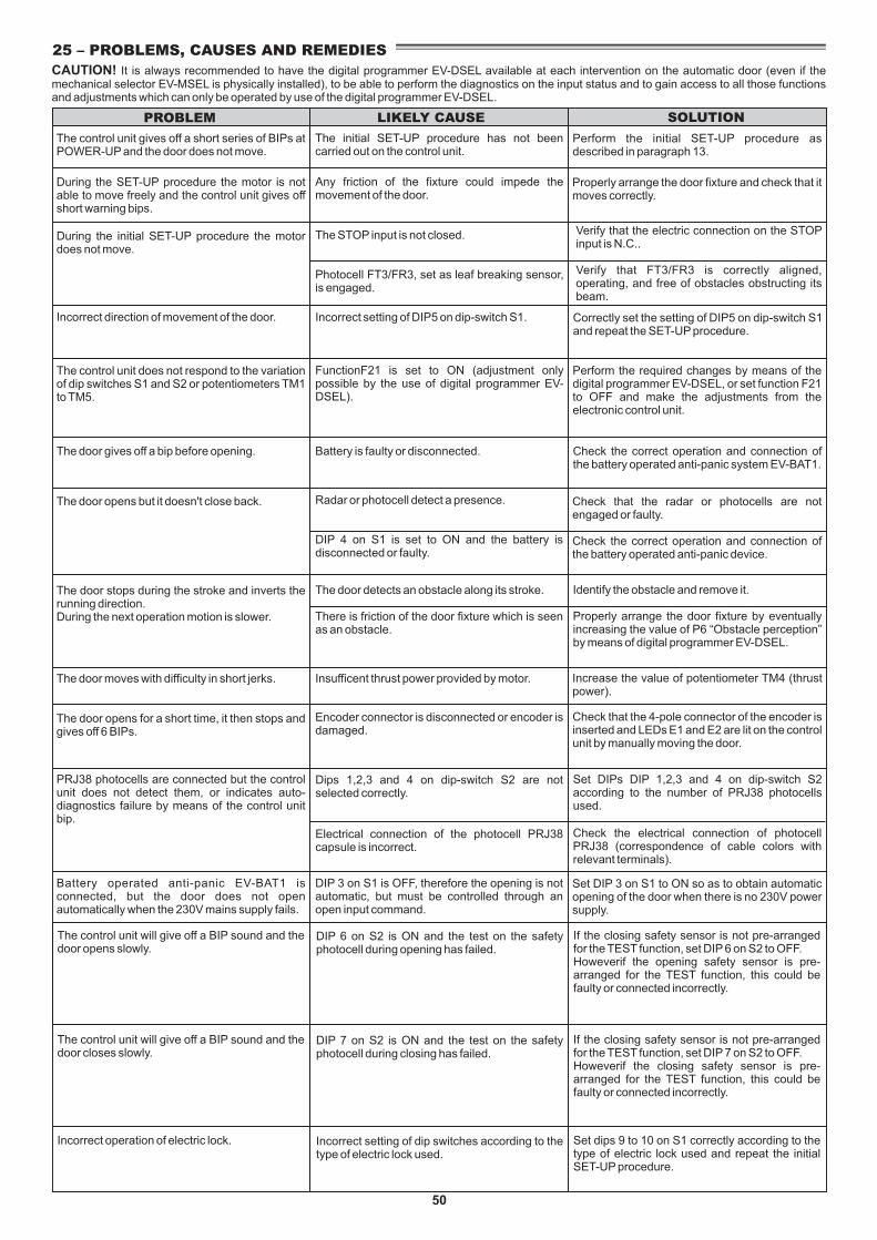
50
PROBLEM LIKELY CAUSE SOLUTION
The control unit gives off a short series of BIPs at POWER-UP and the door does not move.
The initial SET-UP procedure has not been carried out on the control unit.
25 – PROBLEMS, CAUSES AND REMEDIES
The door opens for a short time, it then stops and gives off 6 BIPs.
The door moves with difficulty in short jerks.
The door stops during the stroke and inverts the running direction.During the next operation motion is slower.
The door opens but it doesn't close back.
The door gives off a bip before opening.
The control unit does not respond to the variation of dip switches S1 and S2 or potentiometers TM1 to TM5.
Incorrect direction of movement of the door.
During the initial SET-UP procedure the motor does not move.
During the SET-UP procedure the motor is not able to move freely and the control unit gives off short warning bips.
Encoder connector is disconnected or encoder is damaged.
Insufficent thrust power provided by motor.
The door detects an obstacle along its stroke.
There is friction of the door fixture which is seen as an obstacle.
Radar or photocell detect a presence.
DIP 4 on S1 is set to ON and the battery is disconnected or faulty.
Battery is faulty or disconnected.
FunctionF21 is set to ON (adjustment only possible by the use of digital programmer EV-DSEL).
Incorrect setting of DIP5 on dip-switch S1.
Any friction of the fixture could impede the movement of the door.
Perform the initial SET-UP procedure as described in paragraph 13.
Properly arrange the door fixture and check that it moves correctly.
Correctly set the setting of DIP5 on dip-switch S1 and repeat the SET-UP procedure.
Perform the required changes by means of the digital programmer EV-DSEL, or set function F21 to OFF and make the adjustments from the electronic control unit.
Check the correct operation and connection of the battery operated anti-panic system EV-BAT1.
Check that the radar or photocells are not engaged or faulty.
Check the correct operation and connection of the battery operated anti-panic device.
Identify the obstacle and remove it.
Properly arrange the door fixture by eventually increasing the value of P6 “Obstacle perception” by means of digital programmer EV-DSEL.
Increase the value of potentiometer TM4 (thrust power).
Check that the 4-pole connector of the encoder is inserted and LEDs E1 and E2 are lit on the control unit by manually moving the door.
CAUTION! It is always recommended to have the digital programmer EV-DSEL available at each intervention on the automatic door (even if the mechanical selector EV-MSEL is physically installed), to be able to perform the diagnostics on the input status and to gain access to all those functions and adjustments which can only be operated by use of the digital programmer EV-DSEL.
Battery operated anti-panic EV-BAT1 is connected, but the door does not open automatically when the 230V mains supply fails.
DIP 3 on S1 is OFF, therefore the opening is not automatic, but must be controlled through an open input command.
Set DIP 3 on S1 to ON so as to obtain automatic opening of the door when there is no 230V power supply.
PRJ38 photocells are connected but the control unit does not detect them, or indicates auto-diagnostics failure by means of the control unit bip.
Set DIPs DIP 1,2,3 and 4 on dip-switch S2 according to the number of PRJ38 photocells used.
Check the electrical connection of photocell PRJ38 (correspondence of cable colors with relevant terminals).
Electrical connection of the photocell PRJ38 capsule is incorrect.
Dips 1,2,3 and 4 on dip-switch S2 are not selected correctly.
The control unit will give off a BIP sound and the door opens slowly.
DIP 6 on S2 is ON and the test on the safety photocell during opening has failed.
If the closing safety sensor is not pre-arranged for the TEST function, set DIP 6 on S2 to OFF.Howeverif the opening safety sensor is pre-arranged for the TEST function, this could be faulty or connected incorrectly.
The control unit will give off a BIP sound and the door closes slowly.
DIP 7 on S2 is ON and the test on the safety photocell during closing has failed.
If the closing safety sensor is not pre-arranged for the TEST function, set DIP 7 on S2 to OFF.Howeverif the closing safety sensor is pre-arranged for the TEST function, this could be faulty or connected incorrectly.
Incorrect operation of electric lock. Incorrect setting of dip switches according to the type of electric lock used.
Set dips 9 to 10 on S1 correctly according to the type of electric lock used and repeat the initial SET-UP procedure.
The STOP input is not closed.
Photocell FT3/FR3, set as leaf breaking sensor, is engaged.
Verify that the electric connection on the STOP input is N.C..
Verify that FT3/FR3 is correctly aligned, operating, and free of obstacles obstructing its beam.

Manufacturer: Label S.p.A.
Address: Via Ilariuzzi 17/A - 43126 San Pancrazio Parmense, PARMA - ITALY
Declare that: the operator mod. EVOLUS (type 90 and 150) and mod. EVOLUS-T (type 200 and 300),
Serial number:
realized to control pedestrial sliding automatic doorscomplies with the essential safety requirements of the following directives:
! Low Voltage Directive 2006/95/EC! Electromagnetic Compatibility Directive 2004/108/EC
Label declare that the operator EVOLUS, EVOLUS-T has been realized to be incorporated in a machine or to be assembled with other devices to constitute a machine covered by Machine Directive 2006/42/EC.
Label declare as well that the product cannot be operated until the final machine, where the product is incorporated, has been certified as compliant with the Machine Directive 2006/42/EC.Label undertake to submit, upon suitably justified request of the national authorities, information related to the partly completed machinery.
PERSON AUTHORIZED TO ESTABLISH THE TECHNICAL DOCUMENTATION:Bruno Baron ToaldoVia Ilariuzzi, 17/A43126 - San Pancrazio P.se - Parma
Parma, 01 March 2010
The ChairmanBruno Baron Toaldo
DECLARATION OF INCORPORATION OF PARTLY ASSEMBLED MACHINERY
LABEL S.p.A.Via Ilariuzzi, 17/A - S. Pancrazio P.se - 43126 - PARMA - Italy Tel. (+39) 0521/6752 - Fax (+39) 0521/675222 www.labelspa.it

EVOLU
SEV
OLU
S
LABEL S.p.A.Via U. Ilariuzzi, 17/A - S.Pancrazio P.se - 43126 - Parma
Tel. (+39) 0521/6752 - Fax (+39) 0521/675222www.labelspa.com