italiano - Велосайтmy-sport.spb.ru/manual_1/2003 bomber.pdf · italiano 3 mz001 english...
TRANSCRIPT


Italia
no
3M
Z00
1
Ital
ian
oE
ng
lish
Fra
nça
isD
euts
chE
spañ
ol
BOMBER 2003
ISTRUZIONI PER L’USO E LA MANUTENZIONE
USE AND MAINTENANCE INSTRUCTION MANUAL
MODE D’EMPLOI ET ENTRETIEN
BETRIEBS - UND WARTUNGSANLEITUNG
INSTRUCCIONES PARA EL USO Y MANTENIMIENTO
34
En
glish
MZ
001
Important!The information you will find here below concerns your own safety! Please
read it carefully.
1. REMEMBER THAT INCORRECT USE OF THE FORK CAN BE VERY DANGEROUS FOR YOUROWN SAFETY. Carefully read this manual and follow all of the instructions. Never use a fork that isdamaged in any way during an accident (oil leakage, bent or cracked components, etc). The forkmust be regularly maintained throughout the use of the fork.
2. The fork must be repaired and overhauled by authorized technicians only. Take your fork to the shopwhere you bought it so they can send it to the Marzocchi Authorized Service Center in your country;this will protect your own safety and original spare parts only. Remember that not complying with thisrule will void the warranty.
3. Each time that you use your fork, always remember to check that:
• all fasteners are properly adjusted as shown in the manual (nuts, bolts, etc.);• the tires are inflated to the correct pressure;• none of the components are bent, damaged or out of alignment;• the brakes work perfectly, they are correctly installed and adjusted.
4. Take special care of:
• Installation on the frame. The installation on the frame and the steer tube setting must be carried out incompliance with the manufacturer’s instructions. Do not make any modifications to the steer tubewhen installing the fork onto the frame.
• Components modifications. Do not make any modifications to the components; do not try to slide thestanchion tubes out, always make sure that the fork has the steer tube installed correctly and the diskbrake mounts are perfectly aligned with the calipers. Do not change the position of the fork crown inregard to the stanchion tubes.
5. Marzocchi does not guarantee the installation and refuses all responsibility for damages and/oraccidents that may be caused by an incorrect installation.
6. Not complying with any of the above precautions will immediately void the warranty.
7. Always follow the local bicycle laws and regulations and obey all traffic signals, signs and laws whileyou ride.
General information.The fork you purchased was designed in compliance with the ISO TC 149 Norm (Safety for bicyclesused off road and on rough ground).
MARZOCCHI S.p.A. Via Grazia, 2 - 40069 Lavino di Zola Predosa - BolognaITALYTel - +39 - (0)51 - 61 68 711 - Fax - +39 - (0)51 - 75 88 [email protected] http://www.marzocchi.com
35Contents
En
glis
h
MZ
001
CONTENTS
1 Introduction ................................................................................................................................. 361.1 Conventions .................................................................................................................................. 36
1.1.1 Orientation of the fork ............................................................................................................. 361.1.2 Editorial pictograms ................................................................................................................ 36
1.2 Safety regulations ......................................................................................................................... 371.2.1 Preliminary controls before use .............................................................................................. 371.2.2 Correct behaviour principles during bike’s use ....................................................................... 37
2 Technical information................................................................................................................. 382.1 Use applications............................................................................................................................ 382.2 Fork’s external components .......................................................................................................... 39
2.2.1 Marathon - Mx series.............................................................................................................. 402.2.2 Marathon - Mx series for 29” wheel ........................................................................................ 412.2.3 Z.1 - Dirt Jumper..................................................................................................................... 422.2.4 JR.T - Super T Pro ................................................................................................................. 432.2.5 Shiver SC ............................................................................................................................... 442.2.6 Shiver DC ............................................................................................................................... 45
2.3 Fork’s internal components and fork’s operation .......................................................................... 46
3 Installation ................................................................................................................................... 483.1 Installation on the frame................................................................................................................ 483.2 Installing the brake system ........................................................................................................... 483.3 Fender installing............................................................................................................................ 503.4 Wheel installing with a standard fork’s end ................................................................................... 503.5 Wheel installing with a QR20 Plus fork ......................................................................................... 503.6 Wheel installing with a Shiver fork ................................................................................................ 51
4 Maintenance ................................................................................................................................ 524.1 Problems – Diagnosis – Solutions ................................................................................................ 524.2 Periodical maintenance table ........................................................................................................ 534.3 General safety regulations ............................................................................................................ 534.4 Cleaning the fork legs and the dust seals ..................................................................................... 54
5 Adjustments ................................................................................................................................ 555.1 Preload.......................................................................................................................................... 56
5.1.1 Spring preload ........................................................................................................................ 565.1.2 Air preload .............................................................................................................................. 57
5.2 Negative air................................................................................................................................... 585.3 Cartridge forks rebound adjustment.............................................................................................. 595.4 Externally adjustable forks with SSV rebound adjustment............................................................ 595.5 Internally adjustable forks with SSV rebound adjustment............................................................. 605.6 ECC5 ............................................................................................................................................ 615.7 ETA ............................................................................................................................................... 61
6 Tables........................................................................................................................................... 626.1 Table 1 – Tightening Torques ........................................................................................................ 626.2 Table 2 – Positive air pressure...................................................................................................... 626.3 Table 3 – Negative air pressure .................................................................................................... 62
Notes ............................................................................................................................................ 63
36 Introduction
En
glish
1 INTRODUCTIONCarefully read the instruction given in this manual and keep it for future reference.
This manual contains important information regarding the use and adjustment of the suspension systemthat you have chosen and must therefore be read with extreme care. If you have any questions regardingthe care and maintenance of your suspension system, please contact your nearest service centerdirectly. A list of service centers can be found on the last page of this manual or on the Internet pagewww.marzocchi.com.This manual does not explain how to assemble/disassemble the fork from the bicycle, the wheel, thesteering set or any other component directly or indirectly associated with the fork that are not actually apart of the fork.
The manufacturer therefore reserves the right to make changes to the products, at any time and withoutprior notice to improve the products or to meet any productive or commercial requirements.The user is are the only person responsible for the correct application of the assembly instructions in thepresent manual. Always ride in the full respect of the safety regulations, taking the greatest care.
1.1 Conventions
1.1.1 Orientation of the fork
TOP
BOTTOM
BACK
FRONT LEFT
RIGHT
MZ
0010
01
1.1.2 Editorial pictograms
Descriptions inside the grey boxes contain information, instructions or procedures, which, if not
respected, can cause damage to the forks, injury to the user or damage to the environment.MZ
001
Descriptions in italic contain information, prescriptions or procedures recommended by MARZOCCHI for the bestfork’s use.

37Introduction
En
glis
h
MZ
001
1.2 Safety regulations
Please be advised that if the procedures provided in this manual are not properly performed, or if theinstructions in this manual are not followed, an accident could occur, resulting in serious injury or death ofthe rider.
Please note that throughout this manual, reference is made that “an accident” could occur. Any accidentcould result in damage to your bicycle, its components, and, more importantly, could cause you or abystander to sustain severe personal injury or even death.
• Always strictly follow the given periodical maintenance table (see. Par. 4.2)
• Always use original MARZOCCHI spare parts.
• Never make any modifications whatever to the suspension system.
• Parts that have been bent or otherwise damaged in an accident, or as a result of any other impactmust not be re-straightened. They must be replaced immediately with original MARZOCCHI parts.
• Call directly the Service center closest to you for comments, questions or problems. You will find it onthe web site (www.marzocchi.com)
1.2.1 Preliminary controls before use
Before using the bicycle, always carry out following tests:
• Make sure that all quick release fasteners, nuts and bolts are properly adjusted.
• Bounce the bicycle on the ground and make sure all components remain in the correct position.
• Be sure that your tires are inflated to the correct pressure and that the tread or sidewall are notdamaged.
• Be sure that none of the components of your bicycle are bent, damaged or out of alignment.
• Test your brakes in the beginning of your ride to make sure that they are operating properly.
• Check all reflectors to make sure that they are clean, straight and securely mounted.
1.2.2 Correct behaviour principles during bike’s use
• Follow the local bicycle laws and regulations and obey all traffic signals, signs and laws while you ride.
• Wear close-fitting clothes and which make you visible to traffic, such as neon, fluorescent, or otherbright colors.
• Avoid biking at night, because visibility is lower and it is more difficult for you to see obstructions on theground. If you do ride at night, you must equip your bicycle with a headlight and a taillight.
• When riding in wet conditions, the breaking power is greatly reduced and the adherence of the tires onthe ground is considerably reduced. This makes it harder to control and stop your bicycle. Extra care istherefore required when riding in such conditions, to avoid an accident.
• Always wear a bicycle protection helmet approved by ANSI or SNELL; it must be of the right size andproperly fastened.
38 Technical information
En
glish
2 TECHNICAL INFORMATION
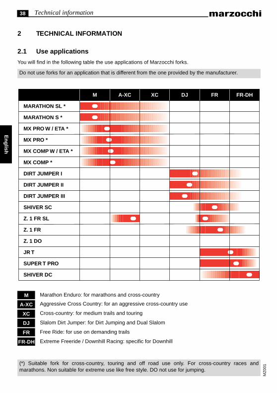
2.1 Use applications
You will find in the following table the use applications of Marzocchi forks.
Do not use forks for an application that is different from the one provided by the manufacturer.
Marathon Enduro: for marathons and cross-country
Aggressive Cross Country: for an aggressive cross-country use
Cross-country: for medium trails and touring
Slalom Dirt Jumper: for Dirt Jumping and Dual Slalom
Free Ride: for use on demanding trails
Extreme Freeride / Downhill Racing: specific for Downhill
MARATHON SL *
MARATHON S *
MX PRO W / ETA *
MX PRO *
MX COMP W / ETA *
MX COMP *
DIRT JUMPER I
DIRT JUMPER II
DIRT JUMPER III
SHIVER SC
Z. 1 FR SL
Z. 1 FR
Z. 1 DO
JR T
SUPER T PRO
SHIVER DC
M A-XC XC DJ FR FR-DH
FR-DH
FR
DJ
XC
A-XC
M
MZ
001(*) Suitable fork for cross-country, touring and off road use only. For cross-country races and
marathons. Non suitable for extreme use like free style. DO not use for jumping.
39Technical information
En
glis
h
MZ
0010
28
A
MZ
001
029
B
MZ
0010
27
C
MZ
001
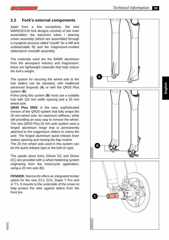
2.2 Fork’s external components
Apart from a few exceptions, the newMARZOCCHI fork designs consists of two mainassemblies: the stanchion tubes / steeringcrown assembly (which are assembled througha cryogenic process called “cryofit” for a stiff andundetachable fit) and the magnesium-moldedsliders/arch monolith assembly.
The materials used are the BAM® aluminiumfrom the aerospace industry and magnesium;these are lightweight materials that help reducethe fork’s weight.
The system for securing the wheel axle to thefork sliders can be standard, with traditionaladvanced dropouts (A) or with the QR20 Plussystem (B).Forks using this system (B) must use a suitablehub with 110 mm width spacing and a 20 mmwheel axle.QR20 Plus 2003: is the new, sophisticatedversion of the QR20 system that fully wraps the20 mm wheel axle, for maximum stiffness, whilestill providing an easy way to remove the wheel.The new QR20 Plus 20 mm axle system uses aforged aluminium hinge that is permanentlyattached to the magnesium sliders to clamp theaxle. The forged aluminium quick-release levermakes opening and closing the flap routine.The 20 mm wheel axle used in this system canbe the quick-release type or the bolt-on type.
The upside down forks (Shiver SC and ShiverDC) are provided with a wheel fastening systemoriginating from the motorcycle application,using a 20 mm axle (C).
FENDER: Marzocchi offers an integrated fenderoption for the new Z1’s, DJ’s, Super T Pro andJr T’s. It mounts to the underside of the crown tohelp protect the rider against debris from thefront tire.
40 Technical information
En
glish
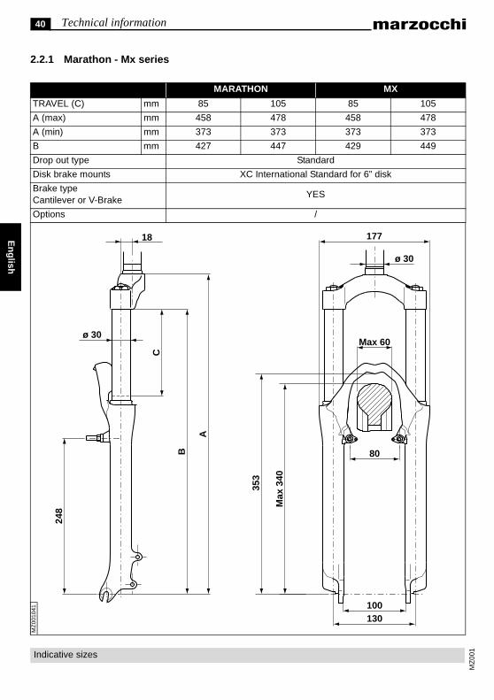
2.2.1 Marathon - Mx series
MARATHON MX
TRAVEL (C) mm 85 105 85 105
A (max) mm 458 478 458 478
A (min) mm 373 373 373 373
B mm 427 447 429 449
Drop out type Standard
Disk brake mounts XC International Standard for 6” disk
Brake type Cantilever or V-Brake
YES
Options /
17718
MZ
0010
41
ø 30
80
100130
ø 30
248
B
A
C
Max
340
353
Max 60
MZ
001
Indicative sizes
41Technical information
h
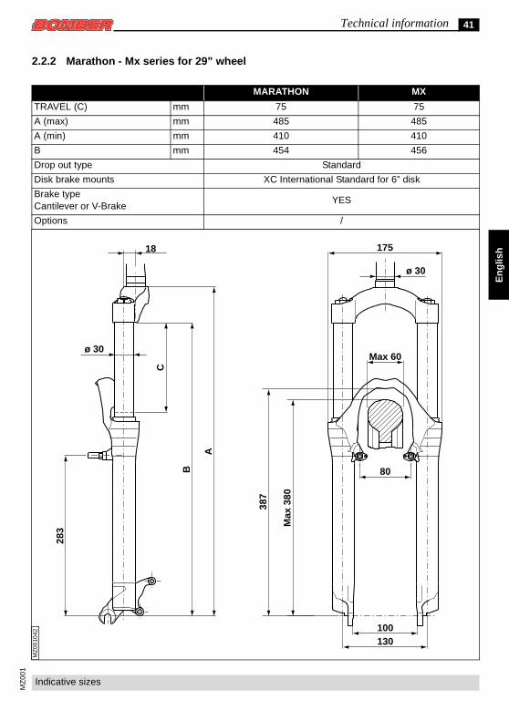
2.2.2 Marathon - Mx series for 29” wheel
MARATHON MX
TRAVEL (C) mm 75 75
A (max) mm 485 485
A (min) mm 410 410
B mm 454 456
Drop out type Standard
Disk brake mounts XC International Standard for 6” disk
Brake type Cantilever or V-Brake
YES
Options /
17518
En
glis
MZ
0010
42
ø 30
80
100130
ø 30
283
B
A
C
Max
380
387
Max 60
MZ
001
Indicative sizes
42 Technical information
En
glish
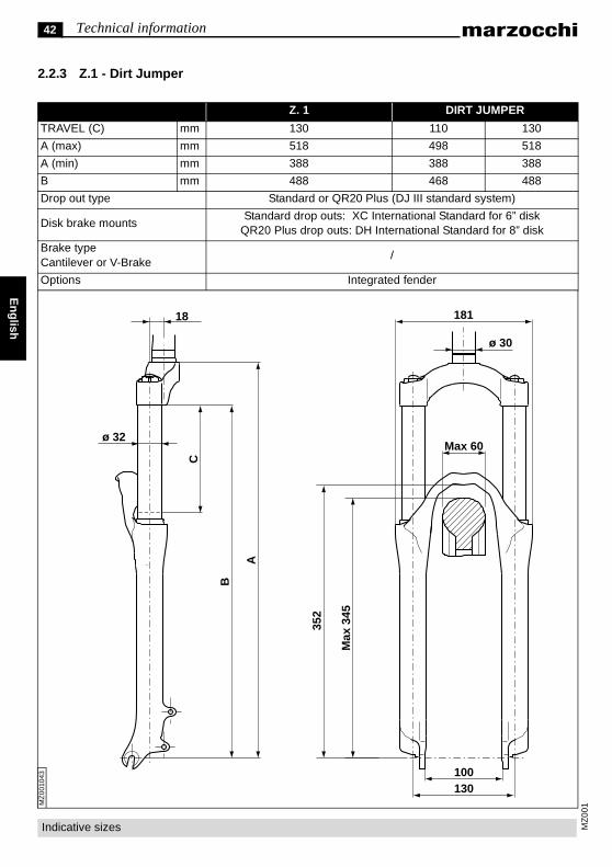
2.2.3 Z.1 - Dirt Jumper
Z. 1 DIRT JUMPER
TRAVEL (C) mm 130 110 130
A (max) mm 518 498 518
A (min) mm 388 388 388
B mm 488 468 488
Drop out type Standard or QR20 Plus (DJ III standard system)
Disk brake mountsStandard drop outs: XC International Standard for 6” disk
QR20 Plus drop outs: DH International Standard for 8” disk
Brake type Cantilever or V-Brake
/
Options Integrated fender
18118
MZ
0010
43
Max 60
ø 30
100130
ø 32
B
A
C
Max
345
352
MZ
001
Indicative sizes
43Technical information
glis
h
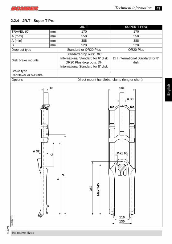
2.2.4 JR.T - Super T Pro
JR. T SUPER T PROTRAVEL (C) mm 170 170A (max) mm 558 558A (min) mm 388 388B mm 528 528Drop out type Standard or QR20 Plus QR20 Plus
Disk brake mounts
Standard drop outs: XC International Standard for 6” disk
QR20 Plus drop outs: DH International Standard for 8” disk
DH International Standard for 8” disk
Brake type Cantilever or V-Brake
/
Options Direct mount handlebar clamp (long or short)
18118
En
MZ
0010
44
ø 32
B
A
C
110130
ø 30M
ax34
5
352
Max 60
MZ
001
Indicative sizes
44 Technical information
En
glish
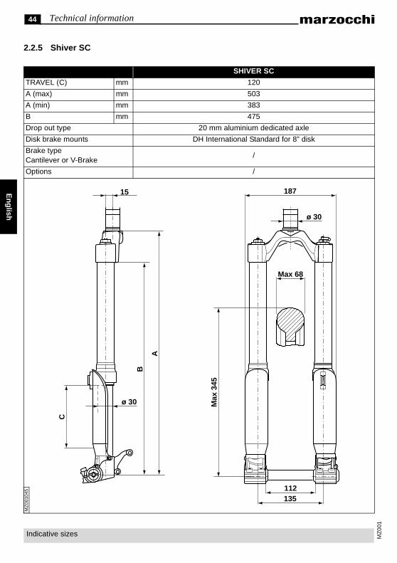
2.2.5 Shiver SC
SHIVER SC
TRAVEL (C) mm 120
A (max) mm 503
A (min) mm 383
B mm 475
Drop out type 20 mm aluminium dedicated axle
Disk brake mounts DH International Standard for 8” disk
Brake type Cantilever or V-Brake
/
Options /
18715
MZ
0010
45
ø 30
Max 68
Max
345
112135
C
ø 30
B
A
MZ
001
Indicative sizes
45Technical information
lish
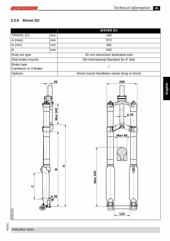
2.2.6 Shiver DC
SHIVER DC
TRAVEL (C) mm 190
A (max) mm 572
A (min) mm 382
B mm 545
Drop out type 20 mm aluminium dedicated axle
Disk brake mounts DH International Standard for 8” disk
Brake type Cantilever or V-Brake
/
Options Direct mount handlebar clamp (long or short)
20825
En
g
MZ
0010
46
110
ø 30
C
B
A
Max
163
ø 35
Max 68
Max
345
MZ
001
Indicative sizes

46 Technical information
En
glish
MZ
001
2.3 Fork’s internal components and fork’s operation
Inside MARZOCCHI forks you will find coil springs or air as a spring system.
The damping load that is generated during the fork legs compression and rebound, can be adjusted bycartridges, controlled by external adjusters, or by special hydraulic valve pumping rods, which operateaccording to compression speed (Speed Sensitive Valving).
Pumping rods can be controlled by external or internal adjusters, or they can have a fixed setting.
Cartridges and pumping rods are fully emerged in oil (Open Bath System). This system provides properlubrication and cooling of the inner sliding parts; furthermore, the oil volume works as a damping andsetting element.
The Open Bath system reduces the maintenance frequency compared to a sealed cartridge system.
Stanchion tubes are guided in the sliders by two teflon-coated bushings, free from static friction.
The seal system prevents oil leaks and contamination from particles entering the fork. It uses a specialdual-lip oil seal and a dust seal at the top of each slider.
You will find here below the different fork damping systems:
ECC5: the new Extension Control Cartridge offers on-the-fly adjustment of the rebound damping with a 5-position clicker. Use the fast rebound position for downhilling, the 3 middle positions for race start sprintsand rough climbing and the fully closed ECC position for steep dirt switchback climbs or Marathon styleroad climbs.
ETA: the new Extension Travel Adjustment locks down the rebound damping like the standard ECC, butstill allows 25 - 30mm of travel.
HSCV: the High-Speed Compression Valve (HSCV) allows lighter damping for better trail sensitivity butstill resists bottoming. It is the best way to provide a controlled damping environment for consistent andperfect damping. The moving valve on the shaft controls rebound and low-speed compression damping.The special valve in the bottom of the cartridge (HSCV), takes the edge of any hard hit to maintaincontrol.
SSV: the Speed Sensitive Valve (SSV) uses 5 valve circuits to control damping rates based on the fork’scompression and rebound speed as well as the fork’s position in the travel.
SSVF: The latest version of our Speed Sensitive Valve has a new Floating valve and spring design. Itincorporates a spring-loaded valve, which is more responsive and uses an external rebound adjuster.

47Technical information
En
glis
h
MZ
001
ForkDamping system
Right leg Left leg
Marathon SL ECC5 hydraulic cartridge Pneumatic cartridge, negative air
Marathon S HSCV cartridge ETA cartridge
Marathon SL 29’ ECC5 hydraulic cartridge Pneumatic cartridge, negative air
MX Pro W/ETASSVF pumping rod with floating valve and external adjustment
ETA cartridge
MX Pro AirSSVF pumping rod with floating valve and external adjustment
/
MX Pro CoilSSVF pumping rod with floating valve and external adjustment
/
MX Pro W/ETA 29’SSVF pumping rod with floating valve and external adjustment
ETA Cartridge
MX Comp W/ETASSV pumping rod with internal adjustment
ETA Cartridge
MX Comp AirSSV pumping rod with internal adjustment
SSV pumping rod with internal adjustment
MX Comp CoilSSV pumping rod with internal adjustment
SSV pumping rod with internal adjustment
MX Comp Coil 29’SSV pumping rod with internal adjustment
SSV pumping rod with internal adjustment
Z1 FR SL ECC5 hydraulic cartridge Pneumatic cartridge, negative air
Z1 FR HSCV cartridge ETA cartridge
Z1 Drop OffSSVF pumping rod with floating valve and external adjustment
ETA cartridge
Dirt Jumper ISSVF pumping rod with floating valve and external adjustment
/
Dirt Jumper IISSV pumping rod with internal adjustment
SSV pumping rod with internal adjustment
Dirt Jumper III Non-adjustable SSV pumping rod Non-adjustable SSV pumping rod
Junior TSSV pumping rod with floating valve and internal adjustment
SSV pumping rod with floating valve and internal adjustment
Super T Pro HSCV cartridge HSCV cartridge
Shiver SC HSCV cartridge ETA cartridge
Shiver DC HSCV cartridge HSCV cartridge

48 Installation
En
glish
3 INSTALLATION
3.1 Installation on the frameThe fork is supplied with “A-Head Set” (threadless) steer tube to be cut according to frame size it will beused on.Installing a MARZOCCHI fork on the bicycle frame is a very delicate operation that must be carried out byspecialized personnel.
The assembling on the frame and the steer tube adjustment must be carried out in compliance with themanufacturer’s instructions. Improper installation may jeopardize the safety of the rider.Marzocchi does not guarantee the installation and refuses all responsibility for damages and/oraccidents that may be caused by an incorrect installation.
The steer tube must be pressed into the crown;
its replacement must be carried out by one ofour service centers only, using the requiredtools.D=
T+
3m
m
MZ
001
007
In case of improper installation of the steertube into the crown, the rider might lose controlof his/her bicycle, thus jeopardizing his/hersafety.On the SHIVER DC model, the sliders areclamped to the lower crown through somebolts: before the installation on the frame, it istherefore necessary to control the boltstightening, and to make sure that the distance“D” between the lower crown and the tire end(inflated) is total travel T+3 mm.
3.2 Installing the brake systemAssembling the brake system is a very delicate operation that must be carried out by specializedpersonnel.
MZ
001
MZ
0010
26
A
B B
A
Marzocchi does not guarantee the assemblyand refuses all responsibility for damages and/or accidents that may be caused by anincorrect assembly.Improper installation of the disk brake systemcan overstress the caliper mountings, whichmay break. The brake system assemblingmust be carried out in compliance with brakesystem’s manufacturers instructions. Improperinstallation may jeopardize the safety of therider.Only use brake systems that are complyingwith the fork’s specifications, considering that:
• On Ø 32 stanchions forks and Upside downforks you can exclusively assemble diskbrake systems.
49Installation
En
glis
h
MZ
001
049
C
MZ
0010
50
D
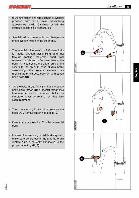
• Ø 30 mm stanchions forks can be previouslyprovided with disk brake assemblingaccessories or with Cantilever or V-Brakesystems assembling accessories.
• Specialized personnel only can change onebrake system type into the other one.
• The monolith sliders-arch of 29” wheel forksis made through assembling and notthrough casting, therefore, apart fromretaining cantilever or V-brake levers, thebolts (A) also secure the upper area of thesliders to the arch. In case of disk brakeassembling, the service centers mayreplace the brake boss bolts (A) with buttonhead bolts (B).
• On the bolts thread (A, C) and on the buttonhead bolts thread (B) a special thread-locktreatment is applied; removed bolts cantherefore never by reused, as they losesuch treatment.
• The user cannot, in any case, remove thebolts (A, C) or the button head bolts (B).
• Do not replace the bolts (C) with commercialbolts.
• In case of assembling of disk brake system,make sure before every ride that the brakesystem tube is correctly connected to theproper mounting (D, E).
MZ
0010
48
E
MZ
001
50 Installation
En
glish
G
F
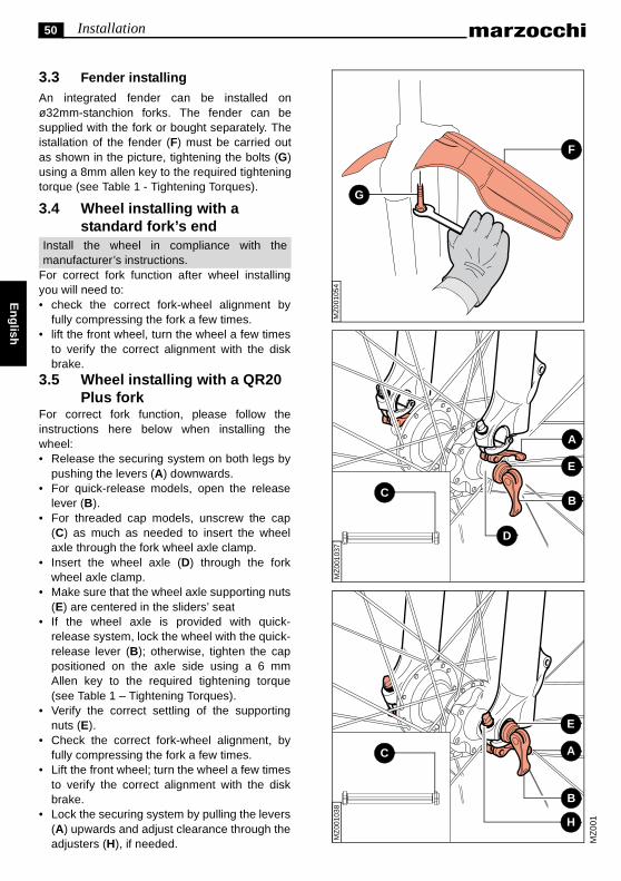
3.3 Fender installing An integrated fender can be installed onø32mm-stanchion forks. The fender can besupplied with the fork or bought separately. Theistallation of the fender (F) must be carried outas shown in the picture, tightening the bolts (G)using a 8mm allen key to the required tighteningtorque (see Table 1 - Tightening Torques).
3.4 Wheel installing with a standard fork’s end
Install the wheel in compliance with the
manufacturer’s instructions.For correct fork function after wheel installing
MZ
001
MZ
0010
38
B
A
E
H
C
MZ
001
037
E
B
D
A
C
MZ
001
054
you will need to:• check the correct fork-wheel alignment byfully compressing the fork a few times.
• lift the front wheel, turn the wheel a few timesto verify the correct alignment with the diskbrake.
3.5 Wheel installing with a QR20 Plus fork
For correct fork function, please follow theinstructions here below when installing thewheel:• Release the securing system on both legs by
pushing the levers (A) downwards.• For quick-release models, open the release
lever (B).• For threaded cap models, unscrew the cap
(C) as much as needed to insert the wheelaxle through the fork wheel axle clamp.
• Insert the wheel axle (D) through the forkwheel axle clamp.
• Make sure that the wheel axle supporting nuts(E) are centered in the sliders’ seat
• If the wheel axle is provided with quick-release system, lock the wheel with the quick-release lever (B); otherwise, tighten the cappositioned on the axle side using a 6 mmAllen key to the required tightening torque(see Table 1 – Tightening Torques).
• Verify the correct settling of the supportingnuts (E).
• Check the correct fork-wheel alignment, byfully compressing the fork a few times.
• Lift the front wheel; turn the wheel a few timesto verify the correct alignment with the diskbrake.
• Lock the securing system by pulling the levers(A) upwards and adjust clearance through theadjusters (H), if needed.

51Installation
En
glis
h
MZ
001
021
A
6 mmM
Z00
1022 B
5 mm
MZ
0010
23
C
MZ
001
3.6 Wheel installing with a Shiver fork
For correct fork function, please follow theinstructions here below when installing thewheel:
• Insert the wheel axle (A) through the rightwheel axle clamp, the wheel and the leftwheel axle clamp.
• Screw down the bolt (B) on the left side andtighten to the required torque (see Table 1 –Tightening Torques).
• Fully compress the fork a few times toproperly align the fork legs.
• Tighten to the required torque (see Table 1 –Tightening Torques) the bolts (C) positionedon both dropouts.
52 Maintenance
En
glish
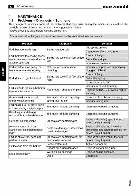
4 MAINTENANCE4.1 Problems – Diagnosis – SolutionsThis paragraph indicates some of the problems that may arise during the fork’s use, as well as thepossible causes of these problems and the suggested solutions.Always check this table before working on the fork.
Operations inside the grey box must be carried out by authorized service centers.
MZ
001
Problem Diagnosis Solution
Fork has too much sag Spring rate too softAdd spring preload
Change to stiffer spring rate
Fork bottoms too easily; needs more than maximum preload to attain proper sag
Spring rate too soft or fork oil too low
Check oil height
Get stiffer springs
Increase air pressure
Forks bottoms too easily, but it has the recommended sag
Not enough compression damping
Increase compression damping by changing oil level
Fork does not get full travelSpring rate too stiff or fork oil too high
Check oil height
Get softer spring
Decrease air pressure
Fork extends too quickly; harsh top-out after impacts
Not enough rebound dampingIncrease rebound damping
Replace oil (SAE 7,5) with a higher viscosity
Front wheel wants to tuck under while cornering
Too much rebound damping; spring rate too soft
Decrease the rebound damping
Increase spring rate
Fork “packs up” or stays down in travel during multiple impacts
Too much rebound damping Decrease rebound damping
Knocking sound during rebound, but no harsh top-out
Too much rebound damping Decrease rebound damping
Oil “ring” on stanchions Oil seals are contaminatedReplace all seals (repair the fork before using it again)
Heavy amount of oil on stanchions; oil dripping down legs
Seals are damaged, stanchions could be damaged
Replace all seals and have the stanchions inspected (repair the fork before using it again)
Fork is sticky; fork does not perform as new
Oil seals are contaminated; fork needs to be serviced
Replace all seals (repair the fork before using it again)
Oil leakage from the bottomLoose bottom nut Tighten bottom nut
Bottom nut o-ring damaged Replace bottom nut o-ring
Loss of sensitivityWorn sliding bushings Replace sliding bushings
Old oil Change oil

53Maintenance
En
glis
h
MZ
001
4.2 Periodical maintenance table
4.3 General safety regulations
After a complete breakdown, always use new seals when reassembling.
To tighten two bolts or nuts that are near each other, always follow the sequence 1-2-1 using the requiredtightening torque (see Table 1 – Tightening Torques).
Never use flammable or corrosive solvents to clean the parts, as these could damage the seals. Ifnecessary use specific detergents that are not corrosive, not flammable or have a high flash point,compatible with the seals materials and preferably biodegradable.
If you are planning not to use your fork for a long time, always lubricate the forks components that are incontact with some fork’s oil.
Never pour lubricants, solvents or detergents which are not completely biodegradable in theenvironment; these must be collected and kept in the relevant special containers, then disposed ofaccording to the regulations in force.
Use only metric spanners, not imperial spanners, which may have similar sizes, but can damage thebolts and make it impossible to unscrew them.
Use the correct size and sort of screwdriver to unscrew slotted or crosshead screws.
When using a screwdriver to assemble or disassemble metal stop rings, o-rings, sliding bushings or sealsegments, avoid scratching or cutting the components with the screwdriver tip.
Only proceed to maintenance/overhaul operations if you are sure you are able to do it and you have gotthe right tools. If this is not the case, or if you are unsure, please contact an authorized service center,where specialized technicians with the right tools and original spare parts will service and overhaul yourfork, putting it back into its original working conditions.
Only use original spare parts.
Work in a clean, ordered and well-lit place; if possible, avoid servicing outdoors.
Polished surfaces need to be periodically treated with some “polishing compound” to be kept as bright asnew.
Carefully check there are no metal shavings or dust in the work area.
Do not modify the fork’s components.
General maintenance operation
Use
Intense Normal
Stanchion and dust seal cleaning
After every ride
Air pressure control Before every ride 10 hours
Oil change 50 hours 100 hours
Oil seals replacement 100 hours 200 hours

54 Maintenance
En
glish
MZ
0010
02
A
B
C
4.4 Cleaning the fork legs and the dust seals
The manufacturer lubricates the fork dust seal withsome grease, which makes the stanchion tubes slideeasier, especially when the fork has not been used fora long time. When using the fork, such grease can melt and stickto the stanchions, looking like an oil leak, although itis not.
• Carefully clean the stanchion tube (A) afterevery use.
• With a small screwdriver pry the dust seal (B)off the slider (C), avoiding scratching thestanchion tube.
• Slide the dust seal along the stanchion tubeand clean inside the dust seal and its seat onthe slider with a jet of compressed air.
It is advisable to tip the fork’s leg to make thepouring of any particles easier.
B
Never use metal tools to clean any particles ofdirt.
MZ
001
MZ
001
003
• Compress the fork legs slightly and removeany traces of dirt from the stanchion tubes.
• Lubricate the dust seal and the visiblesurfaces of the oil seal with some silicongrease.
• Re-assemble the dust seal (C) in its seat,pressing it with your hands.

55Adjustments
5 ADJUSTMENTS
Please visit our web site www.marzocchi.com for any information concerning the travel increase kit andfor different spring rates (K).
En
glis
h
MZ
001
PL Preload
A+ Positive Air Preload
A- Negative Air Preload
REBC Rebound cartridge
PRe External rebound register
PRi Internal rebound register
ECC5 5 position extension control cartridge
ETA Extension travel adjustment cartridge
MARATHON SL
Fork
MARATHON S
MX PRO W / ETA
MX PRO AIR
MX PRO COIL
MX COMP W / ETA
MX COMP AIR
MX COMP COIL
DIRT JUMPER I
DIRT JUMPER II
DIRT JUMPER III
SHIVER SC
Z. 1 FR SL
Z. 1 FR
Z. 1 DO
JR T
SUPER T PRO
SHIVER DC
PL A+ A- PRiPRe ECC5 ETA
5.1.1 5.1.2 5.2 5.55.4 5.6 5.7
REBC
5.3See paragraph

56 Adjustments
En
glish
MZ
0010
04
A
MZ
001
005
A
5.1 Preload
To make the most of the fork’s travel, the saggiven by the rider’s weight must remain between10% and 20% of the total travel length for theXC forks and between 20% and 30% for the DHforks.To reach these values, you will need to use thepreload adjusters of the springs (see paragraph5.1.1 for spring forks) or to modify the fork’spressure (see paragraph 5.1.2. for air forks).
5.1.1 Spring preload
The fork is set to the minimum preload by themanufacturer, i.e. the adjuster knob/screw iscompletely turned counterclockwise. However, thespring is slightly preloaded to help counteractiningstatic load.
By turning the knob (A) on the top of the fork’sleg, you can modify the spring preload to adjustthe initial setting according to the rider’s weightand needs.
• By turning the knob clockwise, the preloadspring can be increased up to the maximumvalue, which corresponds to a springcompression of about 15 mm.
• By turning the knob counterclockwise, you willreduce the preload spring down to theminimum value.
Do not force the adjustment knob past its limits(A).
MZ
001
MZ
0010
06
A
57Adjustments
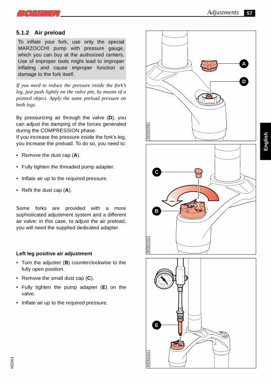
5.1.2 Air preload
To inflate your fork, use only the special
A
D
MARZOCCHI pump with pressure gauge,which you can buy at the authorized centers.Use of improper tools might lead to improperinflating and cause improper function ordamage to the fork itself.
En
glis
h
MZ
001
010
C
B
MZ
0010
08M
Z00
1012
E
MZ
001
If you need to reduce the pressure inside the fork’sleg, just push lightly on the valve pin, by means of apointed object. Apply the same preload pressure onboth legs.
By pressurizing air through the valve (D), youcan adjust the damping of the forces generatedduring the COMPRESSION phase.If you increase the pressure inside the fork’s leg,you increase the preload. To do so, you need to:
• Remove the dust cap (A).
• Fully tighten the threaded pump adapter.
• Inflate air up to the required pressure.
• Refit the dust cap (A).
Some forks are provided with a moresophisticated adjustment system and a differentair valve: in this case, to adjust the air preload,you will need the supplied dedicated adapter.
Left leg positive air adjustment
• Turn the adjuster (B) counterclockwise to thefully open position.
• Remove the small dust cap (C).
• Fully tighten the pump adapter (E) on thevalve.
• Inflate air up to the required pressure.
58 Adjustments
En
glish
A
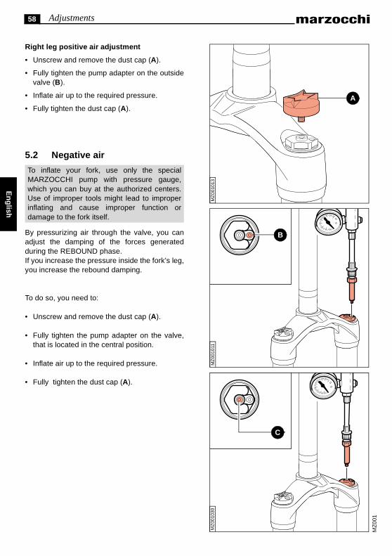
Right leg positive air adjustment
• Unscrew and remove the dust cap (A).
• Fully tighten the pump adapter on the outsidevalve (B).
• Inflate air up to the required pressure.
• Fully tighten the dust cap (A).
5.2 Negative air
MZ
0010
13
To inflate your fork, use only the specialMARZOCCHI pump with pressure gauge,which you can buy at the authorized centers.Use of improper tools might lead to improperinflating and cause improper function ordamage to the fork itself.
MZ
001
MZ
0010
11
B
MZ
0010
30
C
By pressurizing air through the valve, you canadjust the damping of the forces generatedduring the REBOUND phase.If you increase the pressure inside the fork’s leg,you increase the rebound damping.
To do so, you need to:
• Unscrew and remove the dust cap (A).
• Fully tighten the pump adapter on the valve,that is located in the central position.
• Inflate air up to the required pressure.
• Fully tighten the dust cap (A).

59Adjustments
En
glis
h
MZ
0010
14
A
5.3 Cartridge forks rebound adjustment
By rotating the adjustment screw (A), located ontop of the leg, you can control the fork’sREBOUND damping.By turning the adjustment screw and using aproper small flat tip screwdriver, you can adjustthe hydraulic configuration of the inner valves:this means that there will be more or less oilflowing through the valve.
• When turning the adjuster clockwise, you willincrease the rebound hydraulic damping,making the fork return slower during therebound phase.
• When turning the adjuster counterclockwise,you will decrease the rebound hydraulicdamping, making the fork more responsiveduring the rebound phase.
Do not force the adjuster screw (A) past itslimits.
MZ
001
015
B
5.4 Externally adjustable forks with SSV rebound adjustment
When turning the adjustment knob (B) locatedon the bottom of the fork’s leg, you can adjustthe damping during the rebound phase.By turning on the adjustment screw you canmodify the hydraulic configuration of innervalves: this means that there will be more orless oil flowing through the valve.
• When turning the adjuster clockwise, you willincrease the rebound hydraulic damping,making the fork slower during the reboundphase.
• When turning the adjuster counterclockwise,you will decrease the rebound hydraulicdamping, making the fork more responsiveduring the rebound phase.
Do not force the adjuster screw (B) past itslimits.
MZ
001
60 Adjustments
En
glish
21 mm
MZ
0010
16
A
B
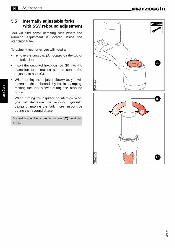
5.5 Internally adjustable forks with SSV rebound adjustment
You will find some damping rods where therebound adjustment is located inside thestanchion tube.
To adjust these forks, you will need to:
• remove the dust cap (A) located on the top ofthe fork’s leg.
• insert the supplied hexagon rod (B) into thestanchion tube, making sure to center theadjustment seat (C).
• When turning the adjuster clockwise, you willincrease the rebound hydraulic damping,making the fork slower during the reboundphase.
• When turning the adjuster counterclockwise,you will decrease the rebound hydraulicdamping, making the fork more responsiveduring the rebound phase.
Do not force the adjuster screw (C) past itslimits.
MZ
001
MZ
001
017
C
61Adjustments
En
glis
h
1
23
4
5
MZ
0010
18
A
B
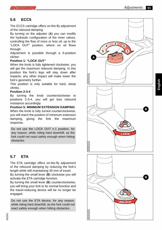
5.6 ECC5
The ECC5 cartridge offers on-the-fly adjustmentof the rebound damping.By turning on the adjuster (A) you can modifythe hydraulic configuration of the inner valves,controlling the flow of more or less oil, up to the“LOCK OUT” position, where no oil flowsthrough.Adjustment is possible through a 5-positionclicker.Position 1: “LOCK OUT”When the knob is fully tightened clockwise, youwill get the maximum rebound damping. In thisposition the fork’s legs will stay down afterimpacts; any other impact will make lower thefork’s geometry further.This position is only suitable for hard, steepclimbs.Position 2-3-4By turning the knob counterclockwise topositions 2-3-4, you will get less reboundresistance accordingly.Position 5: MINIMUM EXTENSION DAMPINGWhen the knob is fully turned counterclockwise,you will reach the position of minimum extensiondamping, giving the fork the maximumresponse.
LOCK
0101
9
Do not use the LOCK OUT n.1 position, forany reason, while riding hard downhill, as thefork could not react safely enough when hittingobstacles.
MZ
0
B
5.7 ETA
The ETA cartridge offers on-the-fly adjustmentof the rebound damping by reducing the fork’slength while still maintaining 30 mm of travel.By turning the small lever (B) clockwise you willactivate the ETA cartridge function.By turning the small lever (B) counterclockwise,you will bring your fork to its normal function andthe travel-reducing device will be no longer beengaged.
UNLOCK
1020
1
Do not use the ETA device, for any reason,while riding hard downhill, as the fork could notreact safely enough when hitting obstacles.
MZ
00
MZ
00

62 Tables
En
glish
MZ
001
6 TABLES
6.1 Table 1 – Tightening Torques
6.2 Table 2 – Positive air pressure
6.3 Table 3 – Negative air pressure
Components to be tightened Tightening Torque (Nm)
Wheel axle bolts 15 ± 1
Wheel axle hex bolts 10 ± 1
Fork’s upper caps 20 ± 1
Bolts for fender tightening 6 ± 1
Rider’s weight Positive air pressure
120 ÷ 155 lbs 55 ÷ 70 kg 30 ÷ 40 psi 2.0 ÷ 2.75 bar c.a
155 ÷ 180 lbs 70 ÷ 80 kg 35 ÷ 45 psi 2.40 ÷ 3.10 bar c.a
180 ÷ 210 lbs 80 ÷ 95 kg 42 ÷ 52 psi 2.90 ÷ 3.80 bar c.a
210 ÷ 220+ lbs 95 ÷ 100+ kg 52 ÷ 65 psi 3.60 ÷ 4.5 bar c.a
Negative air pressure
0 ÷ 150 psi 0 ÷ 10,3 bar c.a

63NotesM
Z00
1
En
glis
h
NOTES
.....................................................................................................................................................................
.....................................................................................................................................................................
.....................................................................................................................................................................
.....................................................................................................................................................................
.....................................................................................................................................................................
.....................................................................................................................................................................
.....................................................................................................................................................................
.....................................................................................................................................................................
.....................................................................................................................................................................
.....................................................................................................................................................................
.....................................................................................................................................................................
.....................................................................................................................................................................
.....................................................................................................................................................................
.....................................................................................................................................................................
.....................................................................................................................................................................
.....................................................................................................................................................................
.....................................................................................................................................................................
.....................................................................................................................................................................
.....................................................................................................................................................................
.....................................................................................................................................................................
.....................................................................................................................................................................
.....................................................................................................................................................................
.....................................................................................................................................................................
.....................................................................................................................................................................
.....................................................................................................................................................................
.....................................................................................................................................................................
.....................................................................................................................................................................
.....................................................................................................................................................................
.....................................................................................................................................................................
.....................................................................................................................................................................
.....................................................................................................................................................................
.....................................................................................................................................................................
.....................................................................................................................................................................
.....................................................................................................................................................................
.....................................................................................................................................................................
.....................................................................................................................................................................
.....................................................................................................................................................................
.....................................................................................................................................................................
.....................................................................................................................................................................
.....................................................................................................................................................................
.....................................................................................................................................................................

Pagina lasciata intenzionalmente bianca - Intentionally blank page Page laissée blanche intentionnellement - Absichtlich leer gelassene Seite - Página intencionalmente vacía


Cod. 900861>A
Mag
gio
- 20
02 -
Edi
zion
e 00
MARZOCCHI S.p.A.Via Grazia, 2
40069 Lavino di Zola Predosa - BolognaITALY
Telefono - +39 - (0)51 - 61 68 711Telefax - +39 - (0)51 - 75 88 57