itc avoximeter manual - home | instrumentation … a disposable cuvette and inserting the cuvette...
TRANSCRIPT

Operator’s Manual
ii
Manufacturing Company Location
Accriva Diagnostics, Inc.
6260 Sequence Drive, San Diego, CA USA
Phone: 1-858-263-2300
Fax: 1-858-314-6700
web site: www.accriva.com
Copyright and Trademarks
Copyright© 2015 Accriva Diagnostics, Inc. All rights reserved. This material may not be reproduced or copied, in whole or in part, without the written permission of Accriva.
Accriva and AVOXimeter are registered trademarks of Accriva Diagnostics, Inc. in the United States and other jurisdictions.
U.S. Patents. 5,430,542 and 6,262,798. Euro/UK Patent 0663070. Other patents pending.
Technical Support
Contact Technical Support at (800) 579-2255 or (858) 263-2502, or by e-mail at [email protected].
iii
Table of Contents
1 INTRODUCTION ...................................................................................................... 1
Intended Use of the AVOXimeter 1000E .................................................................. 1
Summary and Explanation of the Test ...................................................................... 1 Hemodynamic Calculations .......................................................................... 2 Saturation Step-Ups ..................................................................................... 3
Operating Precautions and Warnings ....................................................................... 5
Limitations ................................................................................................................ 5
2 DESCRIPTION ......................................................................................................... 6
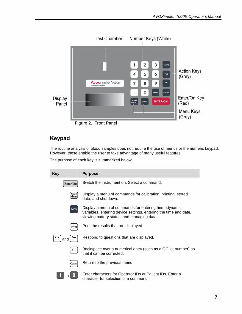
Front Panel............................................................................................................... 6
Keypad ..................................................................................................................... 7
Menus ..................................................................................................................... 8
Test Cuvettes ........................................................................................................... 9
Connections ........................................................................................................... 10
Automatic Standby and Shutdown .......................................................................... 10
Instrument Lockouts ............................................................................................... 10
Instrument Specifications ....................................................................................... 11 Reportable Range ...................................................................................... 11 Accuracy .................................................................................................... 11 Precision .................................................................................................... 11 Interference ................................................................................................ 11
Calibration .............................................................................................................. 12
3 GETTING STARTED ............................................................................................. 13
Unpacking and Inspection ...................................................................................... 13 Materials Provided ...................................................................................... 13 Materials Required But Not Provided.......................................................... 13 Optional Materials ...................................................................................... 14
Charging the Batteries ............................................................................................ 14
Setting Up the Instrument ....................................................................................... 15 Setting Display Backlighting ....................................................................... 15 Specifying Units for Total Hemoglobin (THb) .............................................. 15 Changing the Date and Time ...................................................................... 16 Setting the Standby Delay .......................................................................... 17
Specifying Mandatory Entry of User ID and/or Patient ID ....................................... 18 Changing the QA User ID ........................................................................... 21 Requiring Entry of a Patient ID ................................................................... 22
Specifying Oximetry Site Prompts .......................................................................... 23 Specifying Use of Oximetry Sites ............................................................... 24 Entering a Different Value for Hüfner’s Number .......................................... 25

iv
4 OPERATION ......................................................................................................... 27
Startup ...................................................................................................................27
Entering a User ID (Optional) ..................................................................................27
Entering a Patient ID (Optional) ..............................................................................27
Sample Collection and Preparation .........................................................................28 Sample Collection .......................................................................................28 Sample Preparation ....................................................................................28
Running a Test .......................................................................................................29
Using the Printer .....................................................................................................30 Printing the Current Test Results ................................................................30 Specifying Automatic Printing of Results .....................................................30 Changing the Serial Port Baud Rate and Parity ..........................................30
Data Management ..................................................................................................31 Printing all Stored Data ...............................................................................31 Printing All Optical Quality Control Data ......................................................31 Reviewing and/or Printing the Last Sample ................................................32 Locating, Reviewing, and/or Printing any Sample .......................................32 Aborting Printing of Results ........................................................................33 Purging all Test Records.............................................................................33
Quality Control ........................................................................................................34 Performing Optical Quality Control ..............................................................34 Running Liquid Controls..............................................................................35 Entering Liquid Control Lot Numbers ..........................................................36 Tagging a Liquid Control Test with a Lot Number .......................................37 Enabling QC Lockout ..................................................................................38
Calibration ..............................................................................................................39 Cuvette Pathlength .....................................................................................39 Re-Calibration .............................................................................................39
Shutdown ...............................................................................................................40
Hemodynamic Calculations ....................................................................................41 Entering the Patient Age, Height, Weight, and Sex .....................................41 Oxygen Uptake Rate ..................................................................................43 Body Surface Area ......................................................................................44 Saturation Step-Ups ...................................................................................45 Flow Calculations........................................................................................46 Systemic and Pulmonary Resistances ........................................................50 Stroke Volume and Stroke Index ................................................................52 Printing Hemodynamic Values ....................................................................54
Troubleshooting ......................................................................................................55
5 MAINTENANCE .................................................................................................... 59
Cleaning the Optical Detector .................................................................................59
Replacing the Battery .............................................................................................63

v
6 QUALITY CONTROL LOGS .................................................................................. 65
7 WARRANTY .......................................................................................................... 68
Certification, Warranty and Service Warranty, and Service .................................... 68
8 SAFETY STANDARDS .......................................................................................... 70
Guidance and Manufacturer’s Declaration – Electromagnetic Emissions .................... 70
Guidance and Manufacturer’s Declaration – Electromagnetic Immunity ................. 72
INDEX .......................................................................................................... 73
vi
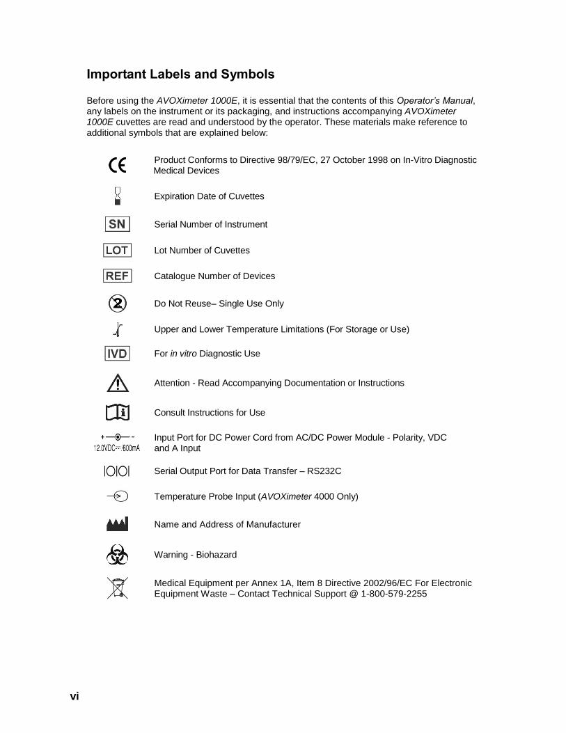
Important Labels and Symbols
Before using the AVOXimeter 1000E, it is essential that the contents of this Operator’s Manual, any labels on the instrument or its packaging, and instructions accompanying AVOXimeter 1000E cuvettes are read and understood by the operator. These materials make reference to additional symbols that are explained below:
Product Conforms to Directive 98/79/EC, 27 October 1998 on In-Vitro Diagnostic Medical Devices
Expiration Date of Cuvettes
Serial Number of Instrument
Lot Number of Cuvettes
Catalogue Number of Devices
Do Not Reuse– Single Use Only
Upper and Lower Temperature Limitations (For Storage or Use)
For in vitro Diagnostic Use
Attention - Read Accompanying Documentation or Instructions
Consult Instructions for Use
Input Port for DC Power Cord from AC/DC Power Module - Polarity, VDC and A Input
Serial Output Port for Data Transfer – RS232C
Temperature Probe Input (AVOXimeter 4000 Only)
Name and Address of Manufacturer
Warning - Biohazard
Medical Equipment per Annex 1A, Item 8 Directive 2002/96/EC For Electronic Equipment Waste – Contact Technical Support @ 1-800-579-2255

AVOXimeter 1000E Operator’s Manual
1
1 Introduction
Intended Use of the AVOXimeter 1000E
The AVOXimeter 1000E is a battery-operated bedside whole blood oximeter that performs individual point-of-care measurements of oxyhemoglobin saturation (%Hb02) and total hemoglobin concentration [THb] on lithium/sodium or heparin or EDTA anticoagulated whole blood samples. Oxygen content [02] of the blood sample is automatically calculated from the %Hb02 and THb measurements.
No sample preparation is required, and analysis is quickly accomplished by injecting the sample into a disposable cuvette and inserting the cuvette into the instrument. The AVOXimeter 1000E then illuminates the sample with multiple wavelengths, records the optical density of the sample at each of the wavelengths, and computes the results. In less than 10 seconds, the oxyhemoglobin fraction, the total hemoglobin concentration, and the oxygen content of the sample are shown in appropriate units on the liquid-crystal display on the front panel.
Data management capabilities are included with the instrument. These capabilities include a combined storage of up to 500 patient, and/or QC results, designation of quality control levels and lot numbers, tagging of test results with date, time, Patient ID and/or Operator ID, entry of oximetry site and subsite, and printing of results.
The instrument also can calculate ten hemodynamic variables (such as body surface area, estimated oxygen consumption rate, and cardiac output using the Fick principle) from data that are entered by the operator. It can also calculate differences in oxygen saturation between adjacent anatomical sites from which blood samples were taken (saturation step-ups), to aid in diagnosing intracardiac and great vessel shunts.
In vitro diagnostic use, For Professional Use, Rx Only
Summary and Explanation of the Test
The AVOXimeter 1000E measures whole blood %Hb02 and [THb] using disposable single-use cuvettes. The operator inserts a whole blood sample into a cuvette, the cuvette is inserted into the test chamber on the instrument, and the results are displayed. The results will remain on the display while the cuvette remains in the instrument.
The result can be automatically printed along with the time and date the test was run, the Patient ID, Operator ID, and other information entered. The result is also saved in an internal database, which has the capability to store up to 500 results.
Individual AVOXimeter 1000E instruments can be customized so that optical quality control tests must be performed whenever a specified period of time has elapsed. In addition, up to three liquid control lot numbers for each level of liquid QC can be stored in the AVOXimeter 1000E and can be tagged to the stored or printed liquid QC records. The instruments can also be configured so that only authorized operators can operate the system and that patient IDs are required for each test run.
The AVOXimeter 1000E measures oxygenated hemoglobin [HbO2], deoxyhemoglobin [HHb], methemoglobin [MetHb], and carboxyhemoglobin [COHb] directly, using novel optics and multiple

AVOXimeter 1000E Operator’s Manual
2
wavelengths. This reduces interference from dyshemoglobins and other interfering substances such as fetal hemoglobin and bilirubin and minimizes the effects of hemolysis.
The measured values are used to calculate total hemoglobin [THb] and percent oxyhemoglobin saturation [%Hb02] of the sample, using the fractional method described below:
[THb] = [HbO2] + [HHb] + [MetHb] + [COHb]
[%HbO2] = [HbO2] x 100
[HbO2] + [HHb] + [MetHb] + [COHb]
Oxygen content [O2] of the sample is then calculated:
[O2] = 1.39 x [THb] x [%HbO2]
100
where 1.39 is the ml of oxygen assumed to be carried by one gram of oxygenated hemoglobin (Hϋfner’s Number). Depending on your facility protocols, the Hϋfner’s Number stored in the AVOXimeter 1000E can be set at any value in the range of 1.30 to 1.39 (see page 25).
Note: Below is a legend for oxygen saturation terminology used throughout this document:
Abbreviation Term Units Displayed
THb Total Hemoglobin g/dl
HbO2 Oxyhemoglobin g/dl
MetHb Methemoglobin g/dl
COHb Carboxyhemoglobin g/dl
HHb Reduced Hemoglobin g/dl
%HbO2 Percent Oxyhemoglobin Saturation (Fractional Oxygen Saturation)
n/a
[O2] Oxygen Content ml/dl
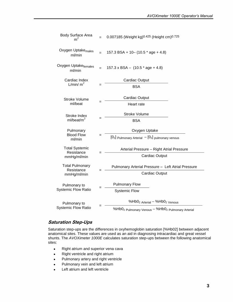
Hemodynamic Calculations
Based on the results, hemodynamic calculations are performed as described below.
Cardiac Output ml/min
= Oxygen Uptake
[O2] arterial - [O2] venous
Note: Oxygen uptake rate can either be measured from expired gases, or it can be estimated from the patient’s age, height, weight, and sex (see below).
AVOXimeter 1000E Operator’s Manual
3
Body Surface Area m
2
= 0.007185 (Weight kg)0.425 (Height cm)0.725
Oxygen Uptakemales
ml/min = 157.3 BSA + 10– (10.5 * age + 4.8)
Oxygen Uptakefemales
ml/min = 157.3 x BSA – (10.5 * age + 4.8)
Cardiac Index
L/min/ m2
=
Cardiac Output
BSA
Stroke Volume ml/beat
= Cardiac Output
Heart rate
Stroke Index ml/beat/m
2
= Stroke Volume
BSA
Pulmonary Blood Flow
ml/min =
Oxygen Uptake
[02] Pulmonary Arterial – [02] pulmonary venous
Total Systemic
Resistance mmHg/ml/min
= Arterial Pressure – Right Atrial Pressure
Cardiac Output
Total Pulmonary
Resistance mmHg/ml/min
= Pulmonary Arterial Pressure – Left Atrial Pressure
Cardiac Output
Pulmonary to Systemic Flow Ratio
= Pulmonary Flow
Systemic Flow
Pulmonary to Systemic Flow Ratio
= %Hb02 Arterial – %Hb02 Venous
%Hb02 Pulmonary Venous – %Hb02 Pulmonary Arterial
Saturation Step-Ups
Saturation step-ups are the differences in oxyhemoglobin saturation [%Hb02] between adjacent anatomical sites. These values are used as an aid in diagnosing intracardiac and great vessel shunts. The AVOXimeter 1000E calculates saturation step-ups between the following anatomical sites:
● Right atrium and superior vena cava
● Right ventricle and right atrium
● Pulmonary artery and right ventricle
● Pulmonary vein and left atrium
● Left atrium and left ventricle

AVOXimeter 1000E Operator’s Manual
4
● Left ventricle and aorta
When calculating saturation step-ups, the AVOXimeter 1000E searches the database for all results for each main oximetry site for that patient (sub-sites are ignored), averages the results for each site, and then calculates the saturation step-ups from the average result for each main site. This information can then be printed from the AVOXimeter 1000E.
Note: Use of average readings rather than individual values improves the precision of saturation step-up calculations.

AVOXimeter 1000E Operator’s Manual
5
Operating Precautions and Warnings
● For in vitro Diagnostic use.
● Do not allow blood, water, or other liquids to enter the instrument.
● The AVOXimeter 1000E instrument is designed for use only with AVOXimeter 1000E cuvettes.
● Do not re-use test cuvettes.
● Always keep cuvettes in sealed bag with desiccant.
● When filling cuvette, do not use excessive pressure on the syringe or cause the vent patch to bulge outward by overfilling the cuvette.
● For proper calibration and calibration verification, use only the controls recommended in this manual. Controls from other sources may yield erroneous results.
● The AVOXimeter 1000E instrument is designed to be used for testing in a stationary position. DO NOT perform testing while carrying or holding the instrument.
● In order to charge the AVOXimeter 1000E instrument, the AC power cord should be plugged into an electrical service outlet and the AC/DC power module while the DC power cord from the AC/DC power module is plugged into the DC port in the back of the instrument.
● DO NOT expose the AVOXimeter 1000E instrument to extreme temperature (above 35°C, 95°F). Such exposure could affect the performance of any type of electronic instrumentation.
● DO NOT drop the AVOXimeter 1000E instrument, and do not use the results if the instrument is dropped during a test.
● Only properly qualified personnel should attempt to open and perform work on the AVOXimeter 1000E instrument as identified in this manual.
● DO NOT remove the AC/DC power module from the AVOXimeter 1000E instrument by pulling on the cord.
● The use of accessory equipment (e.g., printers, etc.) not identified in this manual either in the patient vicinity, or that does not comply with either the equivalent safety requirements of this equipment or IEC/EN 61010-1:2010 or IEC/EN 61010-2-101:2002, may lead to a reduced level of safety with the resulting system.
Any items exposed to human blood, plasma or serum must be handled cautiously as a biohazardous material in accordance with laboratory safety practices and federal and local regulations. Federal, state and local laws and regulations require that hazardous waste be disposed of in a specific manner. Waste material from the AVOXimeter 1000E which may be classified as biohazardous include used cuvettes. It is important that steps be taken to dispose of these materials in accordance with the prevailing regulations in your location.
Limitations
Do not disturb the instrument while a test is in progress. As with all diagnostic tests, AVOXimeter 1000E test results should be scrutinized in light of a specific patient’s condition and therapy. Any results exhibiting inconsistency with the patient’s clinical status should be repeated or supplemented with additional test data.

AVOXimeter 1000E Operator’s Manual
6
2 Description
The AVOXimeter 1000E is a Point of Care device for use at the bedside. It contains a test chamber which performs all operations to measure the oxyhemoglobin saturation (%Hb02), total hemoglobin (THb), and oxygen content (O2) of a whole blood sample after the operator inserts a test cuvette containing the sample into the test chamber.
Each AVOXimeter 1000E is calibrated at the factory. The AVOXimeter 1000E can be operated either from its internal batteries or from the AC adapter. The batteries are charged when the AC Adapter is connected.
Figure 1. AVOXimeter 1000E Oximeter
Front Panel
The front panel (Figure 2) contains the test chamber, a keypad with the key, action and menu keys, number keys, and a display panel. Operator instructions are shown on the display panel, and the operator enters commands and information using the keypad.
When the test is completed, the results are shown on the display panel and stored in system memory.
The display panel is illuminated to enhance visibility in low light conditions. The illumination can be adjusted (or turned off) to conserve power during battery operation.
AVOXimeter 1000E Operator’s Manual
7
Figure 2. Front Panel
Keypad
The routine analysis of blood samples does not require the use of menus or the numeric keypad. However, these enable the user to take advantage of many useful features.
The purpose of each key is summarized below:
Key Purpose
Switch the instrument on. Select a command.
Display a menu of commands for calibration, printing, stored data, and shutdown.
Display a menu of commands for entering hemodynamic variables, entering device settings, entering the time and date, viewing battery status, and managing data.
Print the results that are displayed.
and Respond to questions that are displayed.
Backspace over a numerical entry (such as a QC lot number) so that it can be corrected.
Return to the previous menu.
to Enter characters for Operator IDs or Patient IDs. Enter a character for selection of a command.

AVOXimeter 1000E Operator’s Manual
8
Menus
The principal menus, their commands, and the procedure to access each menu are summarized below:
Note: Press the button at any time to return to the previous menu.
Menu Commands Access
Main Menu
Press the key when a test is not running or another menu is not active.
Calibration Submenu
Press followed by while the main menu is displayed.
Printer Mode Submenu
Press followed by while the main menu is displayed.
Stored Data Submenu
Press followed by while the main menu is displayed.
Data Menu
Press the key when a test is not running or another menu is not active.
Hemodynamics Submenu (Page 1)
Press followed by while the data menu is displayed to display Page 1.
Press + or - while the hemodynamics submenu is displayed to toggle between Page 1 and Page 2.
Hemodynamics Submenu (Page 2)
Device Settings Submenu
Press followed by while the data menu is displayed.
Time, Date, and Battery Submenu
Press followed by while the data menu is displayed.
Data Management Submenu
Press followed by while the data menu is displayed.

AVOXimeter 1000E Operator’s Manual
9
Test Cuvettes
Tests are performed with single-use disposable test cuvettes (Figure 3). Each test cuvette contains a finger grip, filling port, optical window, and a vent patch.
Figure 3. Test Cuvette
A whole blood sample is inserted into a test cuvette by connecting a luer lock syringe, slip syringe or capillary tube containing the whole blood sample to the filling port and then gently pressing the syringe plunger to dispense approximately 50 µL of whole blood into the test cuvette. Air escapes from the vent patch at the end of the test cuvette while the whole blood sample is being inserted. The test cuvette (with the syringe still attached) is then inserted into the test chamber of the instrument (see page 28 for details).
Note: Be sure to handle the cuvette either by the edges or by the finger grip. Refer to the package insert accompanying the test cuvettes for storage and handling instructions.
● Remove any blood or debris from the exterior of the test cuvette before
inserting it into the test chamber.
● After filling the cuvette with blood, inspect the vent patches to ensure they are not bulging out. If a vent patch protrudes, discard the cuvette. Do not insert a cuvette with a protruding vent patch into the test chamber.
BIOHAZARD WARNING: Any items exposed to human blood, plasma or serum must be handled cautiously as a biohazardous material in accordance with laboratory safety practices and federal and local regulations. Federal, state and local laws and regulations require that hazardous waste be disposed of in a specific manner. Waste material from the AVOXimeter 1000E which may be classified as biohazardous include used cuvettes. It is important that steps be taken to dispose of these materials in accordance with the prevailing regulations in your location.
Filling Port
Light Path
Vent Patch
Optical Window
Finger Grip

AVOXimeter 1000E Operator’s Manual
10
Connections
Connections to the AC Adapter and an optional printer (or a computer) are made at the rear of the instrument (
Figure 4).
Use only the AC Adapter provided with the instrument.
Figure 4. Power and Printer Connections
Automatic Standby and Shutdown
The AVOXimeter 1000E enters a low-power standby mode after the instrument has been idle for a specified period of time (the standby delay). The instrument is factory preset for a standby delay time of 60 minutes, but a time of 10 to 180 minutes can be specified (see page 17). To resume normal operation when the instrument is in standby, press and hold down any key for one second.
Note: The AVOXimeter 1000E also enters standby if the battery charge becomes critically low.
The AVOXimeter 1000E shuts down after it has been in standby for 4 hours.
Instrument Lockouts
The instrument can be configured to allow use only by authorized operators and/or to allow use only if Optical Quality Control (OQC) has been performed.
Printer or Computer
AC Adapter
Serial No. Label

AVOXimeter 1000E Operator’s Manual
11
Instrument Specifications
Size 20.3 cm (8.0 in) x 25.4 cm (10.0 in) x 9.5 cm (3.8 in)
Weight 1.8 kg (4 lbs)
Operating Temperature Room temperature (15°C to 30°C, 59°F to 86°F)
Battery Type Nickel Cadmium (NiCad)
Operating Time On Battery
Approximately 8 hours (constant run at medium brightness).
Tests may also be run while the AVOXimeter 1000E is plugged
into the AC/DC power module.
Anticipated Battery Life Approximately 500 charge / discharge cycles
Power Supply/Chargers Input: 100 / 240 VAC, 50 / 60 Hz
Output: 12 VDC, 830 mA
Serial Data Port RS232C
Sample Type Whole blood
Sample Volume 50 µL
Analysis Time 7 to 10 seconds per sample
Analysis Wavelengths 5
Reportable Range %HbO2 0 to 100%
THb 4 to 25 g/dL
[O2 Content] 0 to 35 mL O2/dL
Accuracy %HbO2 ±1 %HbO2
THb (>10 g/dL) ±0.45 g/dL
THb (<10 g/dL) ±0.35 g/dL
Precision %HbO2 0.5 %HbO2
THb 0.3 g/dL
Interference Bilirubin None
Hemolysis None
Carboxyhemoglobin None
Methemoglobin < 1% %HbO2, < 0.2 g/dL THb (THb = 16 g/dL, MetHb < 10%, 7.1 < pH < 7.8)
Fetal Hemoglobin < 1% %HbO2, < 0.45 g/dL THb (THb = 16 g/dL, HbF < 100%)

AVOXimeter 1000E Operator’s Manual
12
Calibration
The AVOXimeter 1000E is factory-calibrated and employs highly stable state-of-the-art light sources. Factory tests indicate that, when used in accordance with this Operator’s Manual and other instructions, the AVOXimeter 1000E is capable of maintaining its calibration for at least two years.
Should recalibration be required contact a Technical Support representative for assistance (see page 39).
Proper calibration also requires entry of the correct cuvette pathlength by the user (see page 39) and use of a customary value for Hüfner’s number (see page 25).
CAUTION: If quality control results are not acceptable, erroneous results are encountered, or error messages are displayed, the most likely cause is contamination of the optical detector by blood or debris, which cannot be resolved by re-calibration. Consult the Troubleshooting section for additional information.
AVOXimeter 1000E Operator’s Manual
13
3 Getting Started
Unpacking and Inspection
Note: Inspect each component for damage when unpacking. If damage is observed, contact your shipping representative immediately.
1. Remove any protective packaging that may be present around the instrument.
2. Examine the packaging material to be sure that the AC adapter, connecting cables, or other components have been removed. The materials that are provided are listed below.
Note: Do not discard the packaging material.
Materials Provided
Item Quantity
AVOXimeter 1000E Instrument 1
AC adapter (Part No. AP5300X)
Power Cord (Part No. HR1235)
1
1
Operator’s Manual 1
Optical Quality Control Filters (Part No. E-QCYO) 2
Note: An AC power cord is supplied only for the 110VAC version of the US/Canada/Japan instrument. For all others, the customer must obtain a 3 conductor AC power cord that is compatible with an IEC 320 connection at the power supply AC inlet and any other local requirements.
Materials Required But Not Provided
Item Quantity
AVOXimeter 1000E Cuvettes (Part No. C100B) As Needed
Liquid Controls (RNA) See page 34 for additional information.
As Needed
AVOXimeter 1000E Operator’s Manual
14
Optional Materials
Item Quantity
Dymo Printer
110 V
220 V
1
Printer Paper As Needed
Charging the Batteries
Charge the batteries before the system is used for the first time.
1. Plug the AC adapter into an electrical service outlet.
2. Connect the AC adapter cord to the power connector on the rear of the instrument.
3. Allow the battery to charge for at least eight hours.
Note: The AC Adapter can remain connected all the time.
4. To ensure adequate charge, leave the instrument connected to the AC adapter for a minimum of eight hours. This eliminates the risk of the instrument powering down during a test.
Fully charged batteries will allow the AVOXimeter 1000E to analyze blood samples continuously for up to 8 hours when the display is set at medium brightness.
Battery power can be conserved by:
● Reducing (or turning off) display backlighting (see page 15).
● Reducing the standby delay (see page 17).
Note: The batteries can suffer from a “memory effect” if they are charged before being completely discharged. For optimal battery performance, discharge completely when possible before charging them. The message “Battery Critical – Connect Charger” will be displayed when the battery is completely discharged.
The message “Battery Critical – Connect Charger” is displayed and the instrument reverts to the standby mode if the battery power is insufficient to complete the test. The AC Adapter must be used for additional tests until the battery is recharged.
Checking the Battery:
1. Display the “Time, Date, and Battery” menu (a submenu of , see page 8).
2. Press followed by to display the battery status:
AVOXimeter 1000E Operator’s Manual
15
3. Press to display the time, date, and battery menu again.
4. Press to return to the previous menu, if desired.
Setting Up the Instrument
The user can specify the display brightness, specify the units that are used for reporting total hemoglobin (THb), change the date and time, and specify the length of time that the instrument is idle before it enters the standby mode.
Setting Display Backlighting
Lighting of the display can be reduced to conserve battery power or increased to improve visibility.
1. Display the “Device Settings” menu (a submenu of , see page 8).
2. Press followed by to display the screen for changing the backlighting:
3. Select the backlighting level (or turn it off) by pressing the corresponding number
key followed by . The backlighting changes accordingly.
4. Press to display the “Device Settings” menu again.
Specifying Units for Total Hemoglobin (THb)
Measured values of total hemoglobin can be expressed in units of mmol/L or g/dL.
1. Display the “Device Settings” menu (a submenu of , see page 8).
2. Press followed by to display the screen for changing the units for total hemoglobin:
3. Press followed by to change the units.
4. Press followed by when the desired units are displayed. The “Device Settings” menu is again displayed.
5. Press to return to the previous menu, if desired.
AVOXimeter 1000E Operator’s Manual
16
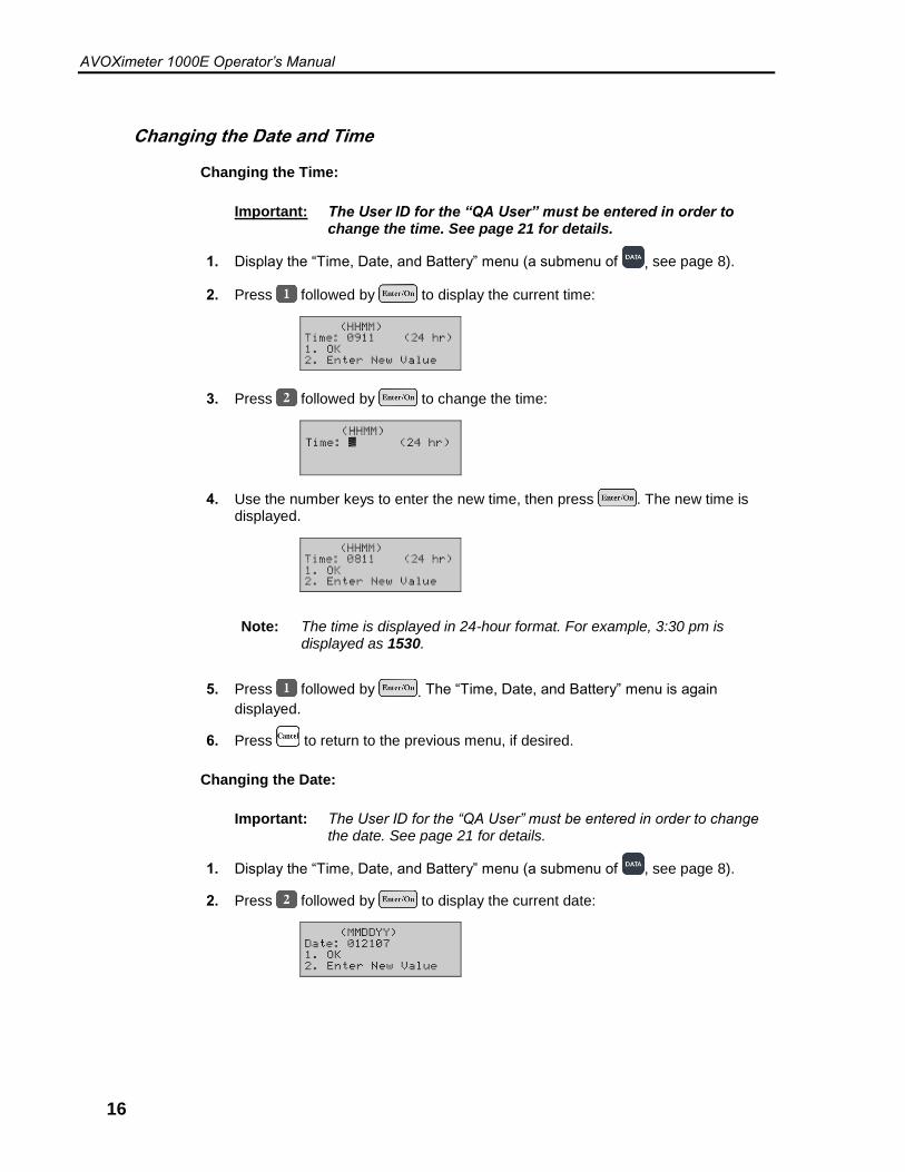
Changing the Date and Time
Changing the Time:
Important: The User ID for the “QA User” must be entered in order to change the time. See page 21 for details.
1. Display the “Time, Date, and Battery” menu (a submenu of , see page 8).
2. Press followed by to display the current time:
3. Press followed by to change the time:
4. Use the number keys to enter the new time, then press . The new time is displayed.
Note: The time is displayed in 24-hour format. For example, 3:30 pm is displayed as 1530.
5. Press followed by . The “Time, Date, and Battery” menu is again
displayed.
6. Press to return to the previous menu, if desired.
Changing the Date:
Important: The User ID for the “QA User” must be entered in order to change the date. See page 21 for details.
1. Display the “Time, Date, and Battery” menu (a submenu of , see page 8).
2. Press followed by to display the current date:

AVOXimeter 1000E Operator’s Manual
17
3. Press followed by to change the date:
4. Use the number keys to enter the new date, then press . The new date is displayed.
5. Press followed by . The “Time, Date, and Battery” menu is again
displayed.
6. Press to return to the previous menu, if desired.
Setting the Standby Delay
The instrument enters a low-power Standby mode after being inactive for a specified length of time (the Standby Delay). The instrument is factory preset for a standby delay time of 60 minutes, but a time of 10 to 180 minutes can be specified.
1. Display the “Device Settings” menu (a submenu of , see page 8).
2. Press followed by to display the standby delay (60 minutes is the factory default value):
3. Press followed by to display the screen for changing the standby delay:
4. Use the number keys to enter the new standby delay (or disable the standby
delay), then press . The new standby delay is displayed.
5. Press followed by . The “Device Settings” menu is again displayed.
6. Press to return to the previous menu, if desired.
AVOXimeter 1000E Operator’s Manual
18
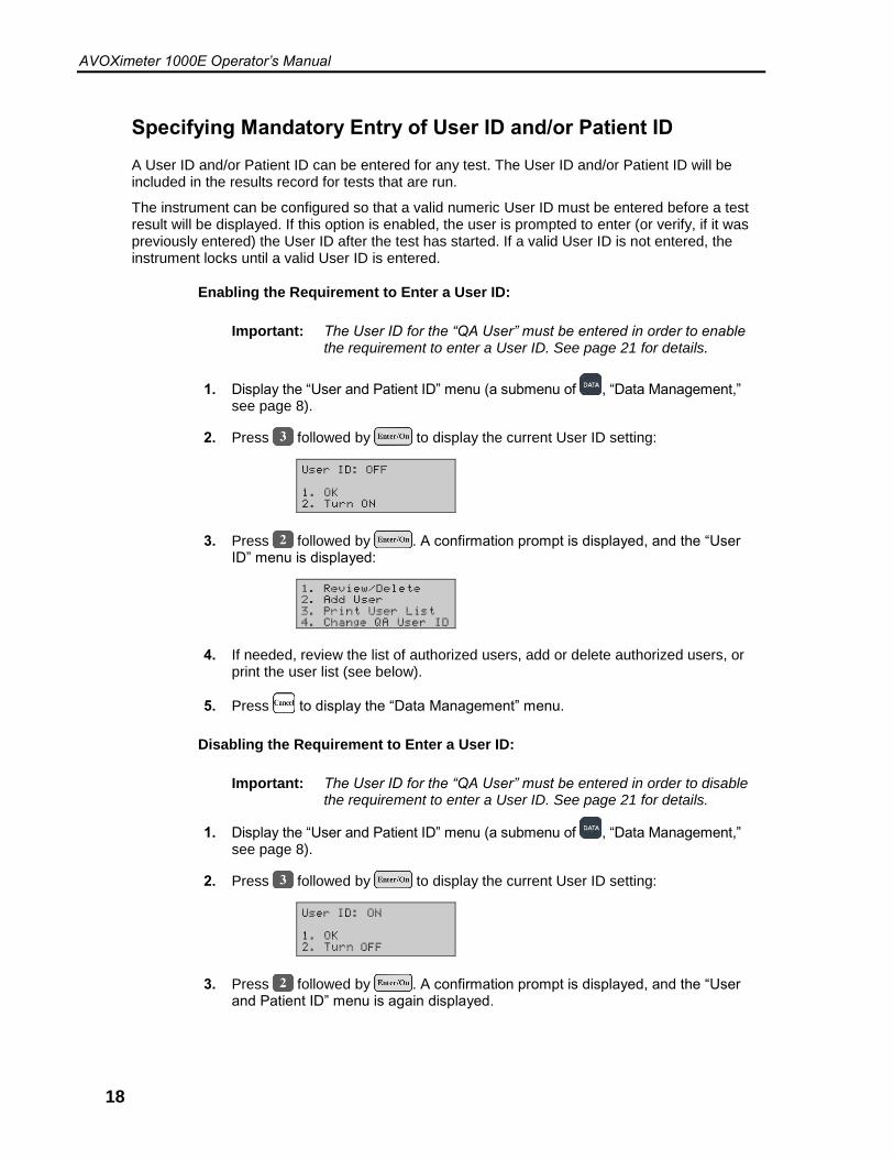
Specifying Mandatory Entry of User ID and/or Patient ID
A User ID and/or Patient ID can be entered for any test. The User ID and/or Patient ID will be included in the results record for tests that are run.
The instrument can be configured so that a valid numeric User ID must be entered before a test result will be displayed. If this option is enabled, the user is prompted to enter (or verify, if it was previously entered) the User ID after the test has started. If a valid User ID is not entered, the instrument locks until a valid User ID is entered.
Enabling the Requirement to Enter a User ID:
Important: The User ID for the “QA User” must be entered in order to enable the requirement to enter a User ID. See page 21 for details.
1. Display the “User and Patient ID” menu (a submenu of , “Data Management,” see page 8).
2. Press followed by to display the current User ID setting:
3. Press followed by . A confirmation prompt is displayed, and the “User ID” menu is displayed:
4. If needed, review the list of authorized users, add or delete authorized users, or print the user list (see below).
5. Press to display the “Data Management” menu.
Disabling the Requirement to Enter a User ID:
Important: The User ID for the “QA User” must be entered in order to disable the requirement to enter a User ID. See page 21 for details.
1. Display the “User and Patient ID” menu (a submenu of , “Data Management,” see page 8).
2. Press followed by to display the current User ID setting:
3. Press followed by . A confirmation prompt is displayed, and the “User and Patient ID” menu is again displayed.
AVOXimeter 1000E Operator’s Manual
19
4. Press to return to the previous menu, if desired.
Note: The current User ID and/or Patient ID must be re-entered if the instrument is idle for longer than 15 minutes or is turned off.
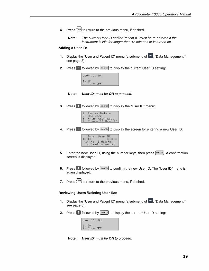
Adding a User ID:
1. Display the “User and Patient ID” menu (a submenu of , “Data Management,”
see page 8).
2. Press followed by to display the current User ID setting:
Note: User ID: must be ON to proceed.
3. Press followed by to display the “User ID” menu:
4. Press followed by to display the screen for entering a new User ID:
5. Enter the new User ID, using the number keys, then press . A confirmation screen is displayed.
6. Press followed by to confirm the new User ID. The “User ID” menu is again displayed.
7. Press to return to the previous menu, if desired.
Reviewing Users /Deleting User IDs:
1. Display the “User and Patient ID” menu (a submenu of , “Data Management,” see page 8).
2. Press followed by to display the current User ID setting:
Note: User ID: must be ON to proceed.

AVOXimeter 1000E Operator’s Manual
20
3. Press followed by to display the “User ID” menu:
4. Press followed by to display the first User ID in the list:
5. Press or to scroll through the list of users. To delete a user, display that
user, press followed by , and respond to the confirmation prompt.
6. Press followed by to display the “User ID” menu.
7. Press to return to the previous menu, if desired.
Printing a List of Users:
1. Prepare the printer (see page 30).
2. Display the “User and Patient ID” menu (a submenu of , “Data Management,” see page 8).
3. Press followed by to display the current User ID setting:
Note: User ID: must be ON to proceed.
4. Press followed by to display the “User ID” menu:
5. Press followed by to print the list. A message is displayed after the list has printed:
6. Press to display the “User ID” menu.
7. Press to return to the previous menu, if desired.

AVOXimeter 1000E Operator’s Manual
21
Changing the QA User ID
The default QA User ID is 123456. The default QA User ID can be changed so that only a user with access to the new QA user ID can change the time and date or change User ID and Patient requirements.
Important: The User ID for the “QA User” must be entered in order to change the QA User ID. If the QA User ID is changed, be sure to record the new QA User ID. If the QA User ID is lost, contact Technical Support for assistance (see page ii).
1. Display the “User and Patient ID” menu (a submenu of , “Data Management,” see page 8).
2. Press followed by to display the current User ID setting:
Note: User ID: must be ON to proceed.
3. Press followed by to display the “User ID” menu:
4. Press followed by , then respond to the confirmation prompt. The screen for entering a new User ID is displayed:
5. Enter the new User ID, using the number keys, then press . A confirmation screen is displayed:
6. Press followed by , then respond to the confirmation prompt. The “User ID” menu is again displayed.
7. Press to return to the previous menu, if desired.

AVOXimeter 1000E Operator’s Manual
22
Requiring Entry of a Patient ID
The instrument can be configured so that a Patient ID must be entered before a test can be run.
Important: The User ID for the “QA User” must be entered in order to enable the requirement to enter a Patient ID. See page 21 for details.
1. Display the “User and Patient ID” menu (a submenu of , “Data Management,” see page 8).
2. Press followed by to display the current Patient ID setting:
3. Press followed by . A screen is displayed for specifying the minimum and maximum number of digits:
4. If the minimum and/or maximum number of digits are to be changed, press
and enter a new value (followed by ) for the minimum and maximum number of digits.
Note: If the minimum and/or maximum number of digits is changed, the instrument will continue to prompt that up to twelve digits is acceptable when entering a Patient ID. Operators should be instructed to ignore this prompt.
5. Respond to the confirmation prompt. The “User and Patient ID” menu is again displayed.
6. Press to return to the previous menu, if desired.
AVOXimeter 1000E Operator’s Manual
23
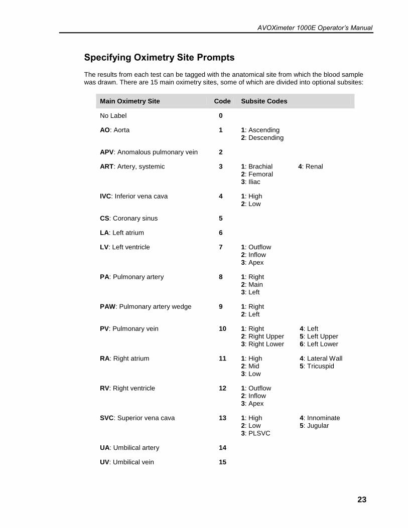
Specifying Oximetry Site Prompts
The results from each test can be tagged with the anatomical site from which the blood sample was drawn. There are 15 main oximetry sites, some of which are divided into optional subsites:
Main Oximetry Site Code Subsite Codes
No Label 0
AO: Aorta 1 1: Ascending 2: Descending
APV: Anomalous pulmonary vein 2
ART: Artery, systemic 3 1: Brachial 2: Femoral 3: Iliac
4: Renal
IVC: Inferior vena cava 4 1: High 2: Low
CS: Coronary sinus 5
LA: Left atrium 6
LV: Left ventricle 7 1: Outflow 2: Inflow 3: Apex
PA: Pulmonary artery 8 1: Right 2: Main 3: Left
PAW: Pulmonary artery wedge 9 1: Right 2: Left
PV: Pulmonary vein 10 1: Right 2: Right Upper 3: Right Lower
4: Left 5: Left Upper 6: Left Lower
RA: Right atrium 11 1: High 2: Mid 3: Low
4: Lateral Wall 5: Tricuspid
RV: Right ventricle 12 1: Outflow 2: Inflow 3: Apex
SVC: Superior vena cava 13 1: High 2: Low 3: PLSVC
4: Innominate 5: Jugular
UA: Umbilical artery 14
UV: Umbilical vein 15

AVOXimeter 1000E Operator’s Manual
24
Specifying Use of Oximetry Sites
If use of oximetry sites is enabled, the instrument prompts the user to specify whether an oximetry site code and subsite code are to be entered whenever a specimen is run.
If is selected, the operator must then enter the numerical code for the main oximetry site from a list displayed on the screen.
If is selected, the result will display in the usual manner.
Note: If the Patient ID is also entered when testing, the AVOXimeter 1000E can calculate Saturation Step-Ups for a patient using the average oxyhemoglobin saturation (%Hb02) values that were obtained at each site during the catheterization.
1. Display the “Data Management” menu (a submenu of , see page 8).
2. Press followed by to display the oximetry screen:
3. Press followed by . A confirmation prompt is displayed and the instrument will prompt the user if they would like to turn on oximetry subsites as
well. Press to turn them on or to leave them turned off. The “Data Management” menu is again displayed.
4. Press to return to the previous menu, if desired.
Note: When use of oximetry sites is enabled, the instrument prompts for entry of the oximetry site code and subsite code during the test procedure (page 29).
AVOXimeter 1000E Operator’s Manual
25
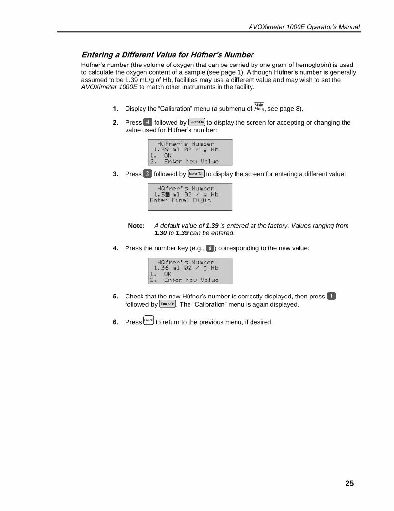
Entering a Different Value for Hüfner’s Number
Hüfner’s number (the volume of oxygen that can be carried by one gram of hemoglobin) is used to calculate the oxygen content of a sample (see page 1). Although Hüfner’s number is generally assumed to be 1.39 mL/g of Hb, facilities may use a different value and may wish to set the AVOXimeter 1000E to match other instruments in the facility.
1. Display the “Calibration” menu (a submenu of , see page 8).
2. Press followed by to display the screen for accepting or changing the value used for Hüfner’s number:
3. Press followed by to display the screen for entering a different value:
Note: A default value of 1.39 is entered at the factory. Values ranging from 1.30 to 1.39 can be entered.
4. Press the number key (e.g., ) corresponding to the new value:
5. Check that the new Hüfner’s number is correctly displayed, then press
followed by . The “Calibration” menu is again displayed.
6. Press to return to the previous menu, if desired.

AVOXimeter 1000E Operator’s Manual
26
This page was left intentionally blank.
AVOXimeter 1000E Operator’s Manual
27
4 Operation
Startup
1. Press . The instrument starts and performs a series of self-tests.
2. “READY” and “Insert Cuvette” are displayed when a test can be run:
3. Run the quality control test(s) for the day (see page 31).
Entering a User ID (Optional)
1. Display the “User and Patient ID” menu (a submenu of , “Data Management,” see page 8).
2. Press followed by to display the screen for entering the User ID:
3. Enter the User ID, then press . A confirmation screen is displayed.
4. Press followed by , then press three times to return to the “READY” and “Insert Cuvette” screen.
Entering a Patient ID (Optional)
Note: Although entering a Patient ID is optional, it is strongly recommended. If Patient ID is not entered, Saturation Step-Ups cannot be computed.
1. Display the “User and Patient ID” menu (a submenu of , “Data Management,” see page 8).
2. Press followed by to display the screen for entering the Patient ID:
3. Enter the Patient ID, then press .
4. Press three times to return to the “READY” - “Insert Cuvette” screen.
AVOXimeter 1000E Operator’s Manual
28
Sample Collection and Preparation
Sample Collection
Collect freshly-drawn whole blood samples in a heparin- or EDTA-anticoagulated syringe. Do not use samples that contain excessive volumes of anticoagulant or are diluted with saline.
Note: Refer to CLSI document H18-A3, entitled “Procedures for the Handling and Processing of Blood Specimens – Approved Guideline, Third Edition” for additional information on sample collection.
CAUTION: Universal safety precautions should be taken when handling and processing samples. Spills should be immediately disinfected with an appropriate disinfectant solution to avoid spreading contamination to laboratory personnel or equipment.
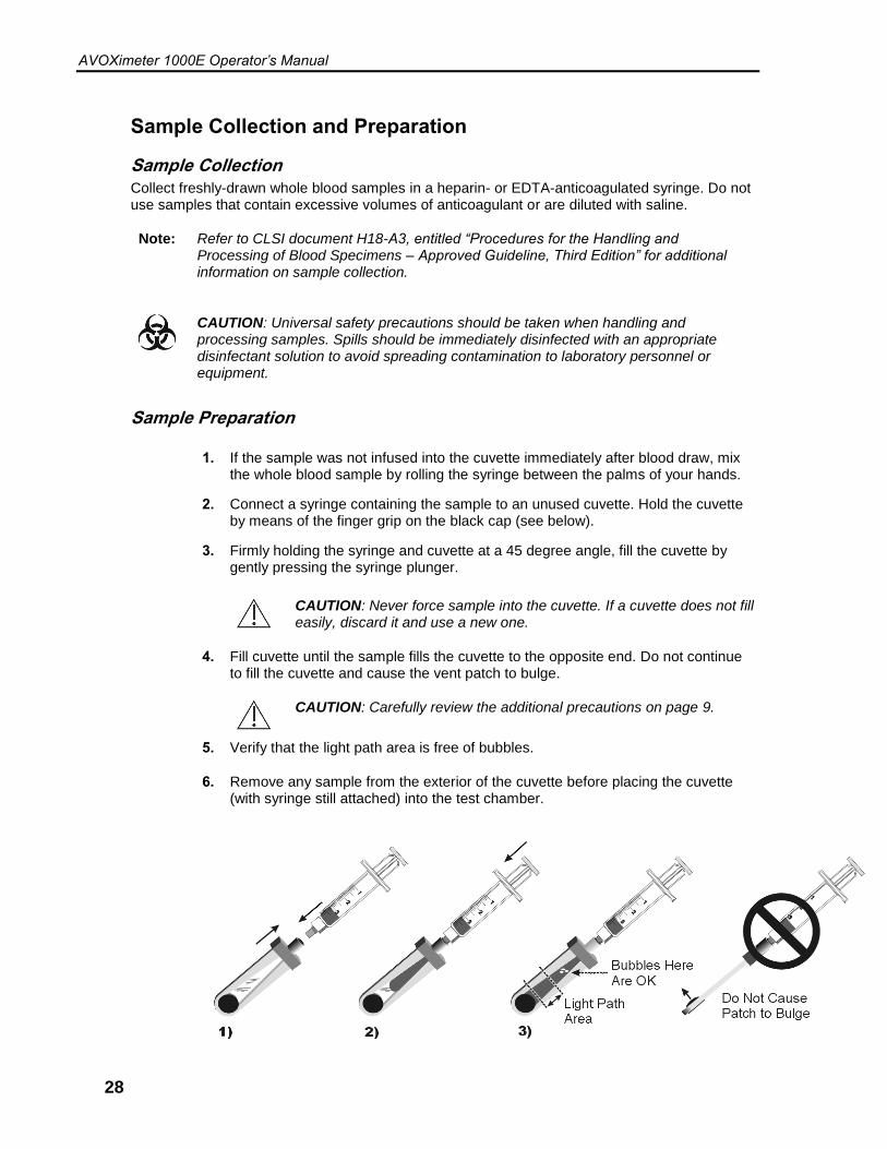
Sample Preparation
1. If the sample was not infused into the cuvette immediately after blood draw, mix the whole blood sample by rolling the syringe between the palms of your hands.
2. Connect a syringe containing the sample to an unused cuvette. Hold the cuvette by means of the finger grip on the black cap (see below).
3. Firmly holding the syringe and cuvette at a 45 degree angle, fill the cuvette by gently pressing the syringe plunger.
CAUTION: Never force sample into the cuvette. If a cuvette does not fill easily, discard it and use a new one.
4. Fill cuvette until the sample fills the cuvette to the opposite end. Do not continue to fill the cuvette and cause the vent patch to bulge.
CAUTION: Carefully review the additional precautions on page 9.
5. Verify that the light path area is free of bubbles.
6. Remove any sample from the exterior of the cuvette before placing the cuvette (with syringe still attached) into the test chamber.

AVOXimeter 1000E Operator’s Manual
29
Running a Test
1. Enter the User ID and/or Patient ID, if desired (see page 27).
2. Verify that the instrument is ready to run a test and that the “READY” - “Insert Cuvette” screen is displayed:
3. Holding the cuvette by the finger grip on the black cap, insert the cuvette (with the syringe still attached) into the test chamber, as shown below.
Important: Always keep the syringe attached when inserting the cuvette into the test chamber. Removing the syringe may cause inaccurate results.
Note: If an optical quality control test is being run, insert the yellow or orange filter instead of the cuvette. If use of oximetry sites is enabled (page 24), enter the site information when prompted.
CAUTION: Never inject sample directly into the test chamber.
CAUTION: Carefully review the additional precautions on page 9.
4. Test results are displayed within ten seconds:
5. Holding the cuvette by the finger grip on the black cap, remove the cuvette from the test chamber.
Textured Vent Patch
AVOXimeter 1000E Operator’s Manual
30
Using the Printer
An optional printer can be connected by means of the serial port at the rear of the instrument (see page 10).
Note: Contact your Accriva representative to purchase the optional printer.
Printing the Current Test Results
1. When the test results are displayed on the screen, press .
Specifying Automatic Printing of Results
The instrument can be configured so that results are automatically printed at the end of a test.
1. Display the “Printer Mode” menu (a submenu of , see page 8).
2. Press followed by to display the automatic printing screen:
3. Press followed by . A confirmation prompt is displayed, and the “Printer Mode” menu is again displayed.
4. Press to return to the previous menu, if desired.
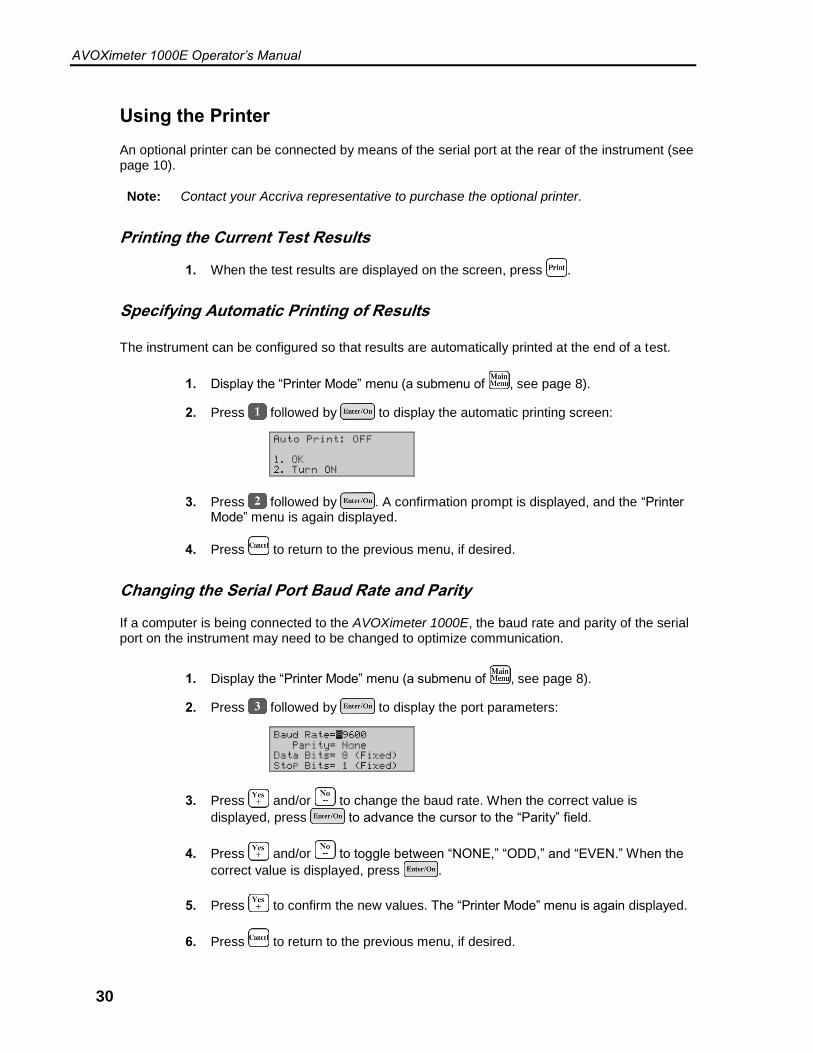
Changing the Serial Port Baud Rate and Parity
If a computer is being connected to the AVOXimeter 1000E, the baud rate and parity of the serial port on the instrument may need to be changed to optimize communication.
1. Display the “Printer Mode” menu (a submenu of , see page 8).
2. Press followed by to display the port parameters:
3. Press and/or to change the baud rate. When the correct value is
displayed, press to advance the cursor to the “Parity” field.
4. Press and/or to toggle between “NONE,” “ODD,” and “EVEN.” When the
correct value is displayed, press .
5. Press to confirm the new values. The “Printer Mode” menu is again displayed.
6. Press to return to the previous menu, if desired.

AVOXimeter 1000E Operator’s Manual
31
Data Management
Stored results can be reviewed, printed, and purged (if desired).
Printing all Stored Data
1. (If needed) Turn on the printer.
2. Display the “Printer Mode” menu (a submenu of , see page 8).
3. Press followed by . All test records are printed, beginning with the latest test. The record number is displayed as each record is printed:
4. When printing is completed, the “Printer Mode” menu is again displayed.
5. Press to return to the previous menu, if desired.
Printing All Optical Quality Control Data
1. (If needed) Turn on the printer.
2. Display the “Printer Mode” menu (a submenu of , see page 8).
3. Press followed by . All optical quality control test records are printed, beginning with the latest test. The record number is displayed as each record is printed:
4. When printing is completed, the “Printer Mode” menu is again displayed.
5. Press to return to the previous menu, if desired.
AVOXimeter 1000E Operator’s Manual
32
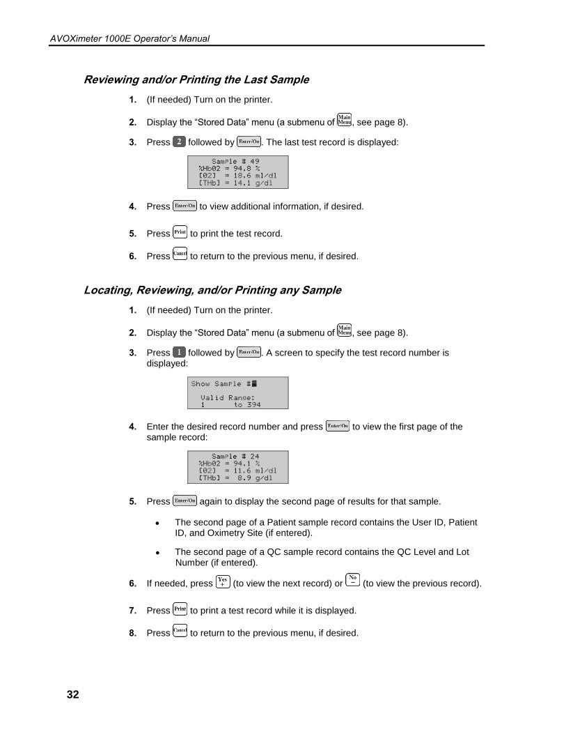
Reviewing and/or Printing the Last Sample
1. (If needed) Turn on the printer.
2. Display the “Stored Data” menu (a submenu of , see page 8).
3. Press followed by . The last test record is displayed:
4. Press to view additional information, if desired.
5. Press to print the test record.
6. Press to return to the previous menu, if desired.
Locating, Reviewing, and/or Printing any Sample
1. (If needed) Turn on the printer.
2. Display the “Stored Data” menu (a submenu of , see page 8).
3. Press followed by . A screen to specify the test record number is displayed:
4. Enter the desired record number and press to view the first page of the sample record:
5. Press again to display the second page of results for that sample.
● The second page of a Patient sample record contains the User ID, Patient ID, and Oximetry Site (if entered).
● The second page of a QC sample record contains the QC Level and Lot Number (if entered).
6. If needed, press (to view the next record) or (to view the previous record).
7. Press to print a test record while it is displayed.
8. Press to return to the previous menu, if desired.

AVOXimeter 1000E Operator’s Manual
33
Aborting Printing of Results
1. Press while results are printing to discontinue printing of additional results. A confirmation prompt is displayed, indicating that all samples were not printed.
2. Press to return to the previous menu.
Purging all Test Records
1. Display the “Stored Data” menu (a submenu of , see page 8).
2. Press followed by . A confirmation prompt is displayed:
3. Press to confirm.
Note: Purging test records may take up to two minutes. “Purging Data…” is displayed on the screen while the purge is being performed.
4. When the purge is completed, “All Data Purged” is displayed on the screen, then the “Stored Data” menu is again displayed.
5. Press to return to the previous menu, if desired.
AVOXimeter 1000E Operator’s Manual
34
Quality Control
Good laboratory practice recommends that routine quality control testing should be part of a comprehensive quality assurance program. Quality control testing of the AVOXimeter 1000E consists of the following operations:
● Daily optical quality control.
● Weekly testing of one level of liquid controls.
In addition, the AVOXimeter 1000E performs a “self-check” to verify that the light source is operating properly every time it is turned on.
Note: If quality control results are out of range, refer to the Troubleshooting section for instructions. If the “self-check” fails, contact Technical Support (see page ii).
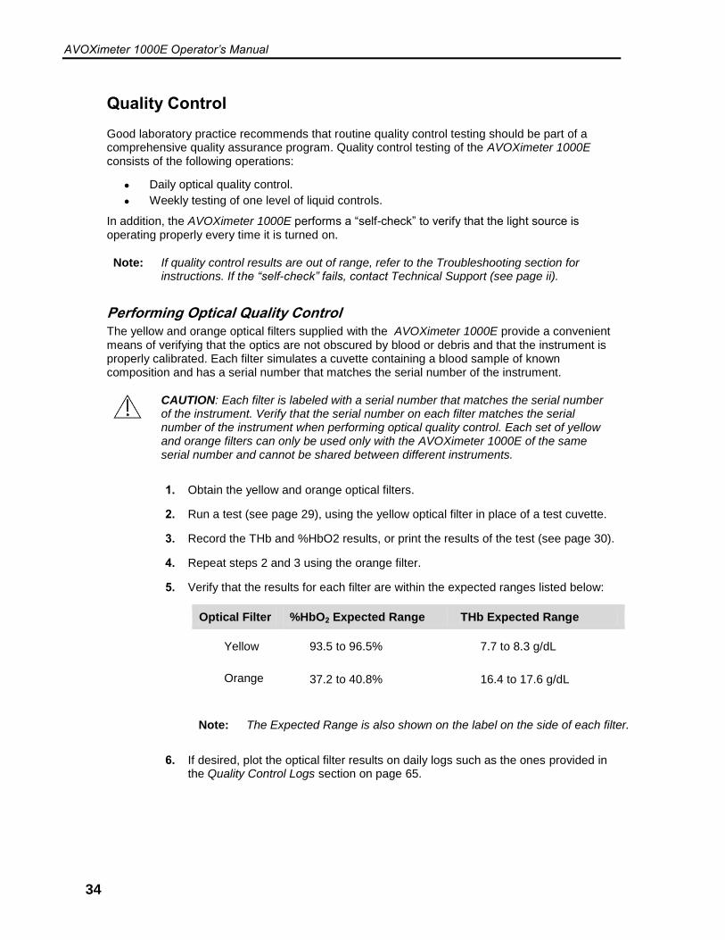
Performing Optical Quality Control The yellow and orange optical filters supplied with the AVOXimeter 1000E provide a convenient means of verifying that the optics are not obscured by blood or debris and that the instrument is properly calibrated. Each filter simulates a cuvette containing a blood sample of known composition and has a serial number that matches the serial number of the instrument.
CAUTION: Each filter is labeled with a serial number that matches the serial number of the instrument. Verify that the serial number on each filter matches the serial number of the instrument when performing optical quality control. Each set of yellow and orange filters can only be used only with the AVOXimeter 1000E of the same serial number and cannot be shared between different instruments.
1. Obtain the yellow and orange optical filters.
2. Run a test (see page 29), using the yellow optical filter in place of a test cuvette.
3. Record the THb and %HbO2 results, or print the results of the test (see page 30).
4. Repeat steps 2 and 3 using the orange filter.
5. Verify that the results for each filter are within the expected ranges listed below:
Optical Filter %HbO2 Expected Range THb Expected Range
Yellow 93.5 to 96.5% 7.7 to 8.3 g/dL
Orange 37.2 to 40.8% 16.4 to 17.6 g/dL
Note: The Expected Range is also shown on the label on the side of each filter.
6. If desired, plot the optical filter results on daily logs such as the ones provided in the Quality Control Logs section on page 65.

AVOXimeter 1000E Operator’s Manual
35
Running Liquid Controls
It is recommended to use the following liquid controls.
● RNA Medical CO-Oximeter controls, available from RNA Medical, Devens, MA., phone 978 772-9070 or toll-free 800-533-6162.
1. Fill a test cuvette with a liquid control (see page 28).
2. Run a test (see page 29).
3. Record the THb and %HbO2 results, or print the results of the test (see page 30).
4. Verify that the results are within the expected range of values for the liquid control.

AVOXimeter 1000E Operator’s Manual
36
Entering Liquid Control Lot Numbers
Three lot numbers for each of three levels of liquid control can be entered into the instrument for later reference.
Note: Lot numbers of liquid controls can be manually tagged to each liquid QC test as it is run (see page 37).
1. Display the “Data Management” menu (a submenu of , see page 8).
2. Press followed by to display a menu for selection of a control level:
3. Select the level for which a lot number is to be added and press . A menu for selection of a lot number is displayed:
4. Select the lot to be changed and press . A screen for entry of the lot number is displayed:
5. Press followed by to enter a new value.
6. Enter the new lot number, using the number keys, then press . A confirmation screen is displayed.
7. Press followed by to confirm the new lot number. The “Data Management” menu is again displayed.
8. Press to return to the previous menu, if desired.
AVOXimeter 1000E Operator’s Manual
37
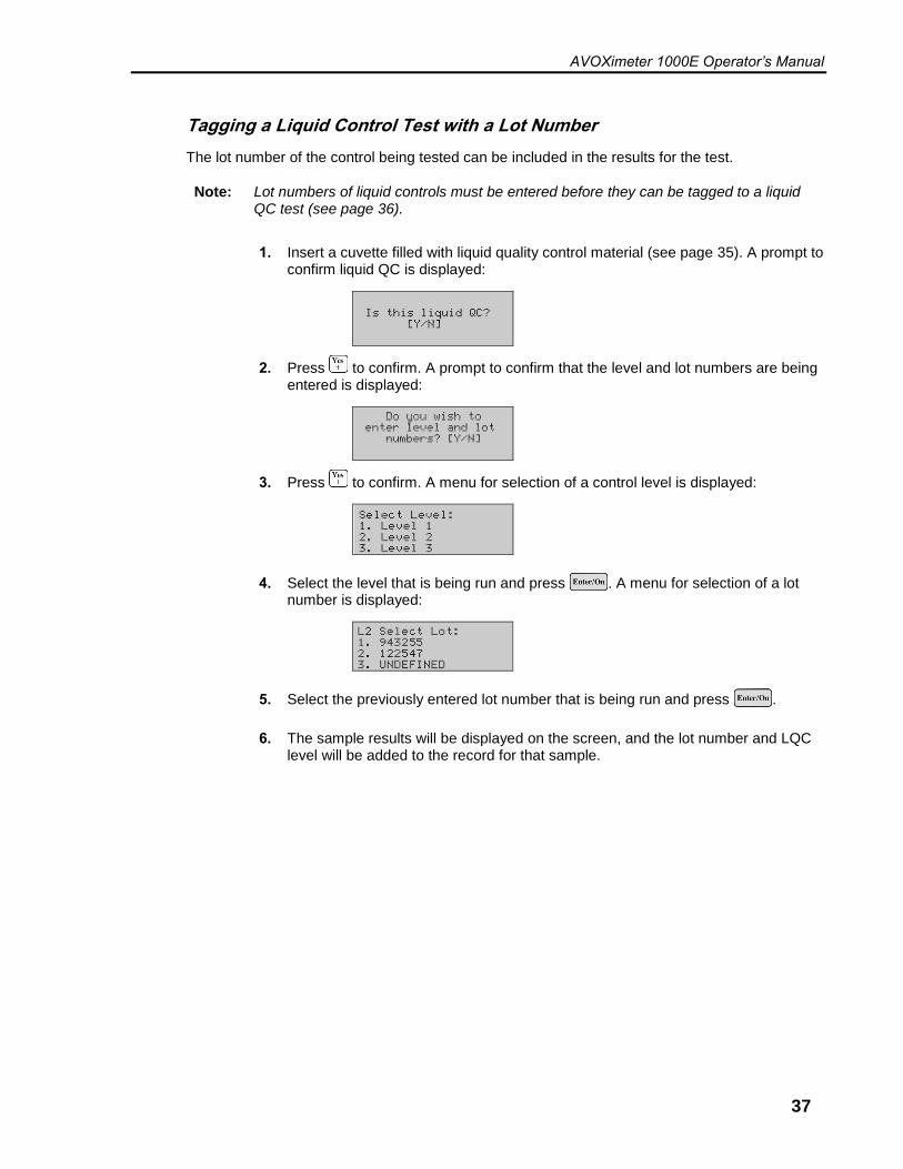
Tagging a Liquid Control Test with a Lot Number
The lot number of the control being tested can be included in the results for the test.
Note: Lot numbers of liquid controls must be entered before they can be tagged to a liquid QC test (see page 36).
1. Insert a cuvette filled with liquid quality control material (see page 35). A prompt to confirm liquid QC is displayed:
2. Press to confirm. A prompt to confirm that the level and lot numbers are being entered is displayed:
3. Press to confirm. A menu for selection of a control level is displayed:
4. Select the level that is being run and press . A menu for selection of a lot number is displayed:
5. Select the previously entered lot number that is being run and press .
6. The sample results will be displayed on the screen, and the lot number and LQC level will be added to the record for that sample.

AVOXimeter 1000E Operator’s Manual
38
Enabling QC Lockout
If QC Lockout is enabled, the operator cannot run a test if optical quality control is not successfully run at the specified intervals.
Note: The User ID for the “QA User” must be entered in order to enable QC Lockout and specify the interval for running optical quality control. See page 21 for details.
1. Display the “Data Management” menu (a submenu of , see page 8).
2. Press followed by to display the current QC Lockout setting:
3. Press followed by . A screen is displayed for specifying the interval between optical quality control tests:
4. To change the interval, press and enter a new value (followed by ). The “Data Management” menu is again displayed.
5. Press to return to the previous menu, if desired.

AVOXimeter 1000E Operator’s Manual
39
Calibration
The AVOXimeter 1000E is factory-calibrated and employs highly stable state-of-the-art light sources.
Cuvette Pathlength
Accuracy of total hemoglobin measurements depends on using the correct cuvette pathlength (see page 1). The user must check the pathlength whenever using a different lot number of cuvettes.
Note: The cuvette lot number and pathlength are included on the carton label and bag for each lot of cuvettes.
Entering a Different Cuvette Pathlength:
1. Display the “Calibration” menu (a submenu of , see page 8).
2. Press followed by to display the screen for entering the cuvette pathlength:
3. To change the interval, press and enter a new value:
Note: Pathlengths ranging from 90 microns to 132 microns can be entered.
4. To change the interval, press and enter a new value.
5. Check that the new pathlength is correctly displayed, then press . The “Calibration” menu is again displayed:
6. Press to return to the previous menu, if desired.
Re-Calibration If the AVOXimeter 1000E results are out of range with either blood samples or controls and troubleshooting does not resolve the issue, re-calibration may be necessary. Please contact Technical Support for more information on re-calibration.
AVOXimeter 1000E Operator’s Manual
40
Shutdown
1. Press (see page 8).
2. Press followed by . The instrument will shut down.
Or:
1. Simultaneously press and . The instrument will shut down.

AVOXimeter 1000E Operator’s Manual
41
Hemodynamic Calculations
The AVOXimeter 1000E can calculate ten hemodynamic variables (such as body surface area, estimated oxygen consumption rate, and cardiac output using the Fick principle) from data that is entered by the operator or measured by the instrument. It can also calculate differences in oxygen saturation between adjacent anatomical sites (Saturation Step-Ups) from which blood samples were taken, to aid in diagnosing intracardiac and great vessel shunts.
Entering the Patient Age, Height, Weight, and Sex
The patient’s age, height, weight, and sex are used to calculate the patient’s body surface area and rate of oxygen consumption.
1. Display page 1 of the “Hemodynamics” menu (a submenu of , see page 8).
2. Press followed by to display the screen for entering the patent’s age:
Note: If an age is already displayed, delete numerals from the right by pressing once for each numeral to be deleted.
3. Enter the age using the number keys, then press . A confirmation prompt is displayed:
4. Check that the age is correctly displayed, then press to confirm. The screen for selecting the units for patent’s height is displayed:
5. Select (for inches) or (for centimeters), then press . The screen for entering the patent’s height is displayed:
Note: If a height is already displayed, delete numerals from the right by pressing once for each numeral to be deleted.
6. Enter the height using the number keys, then press . A confirmation prompt is displayed:
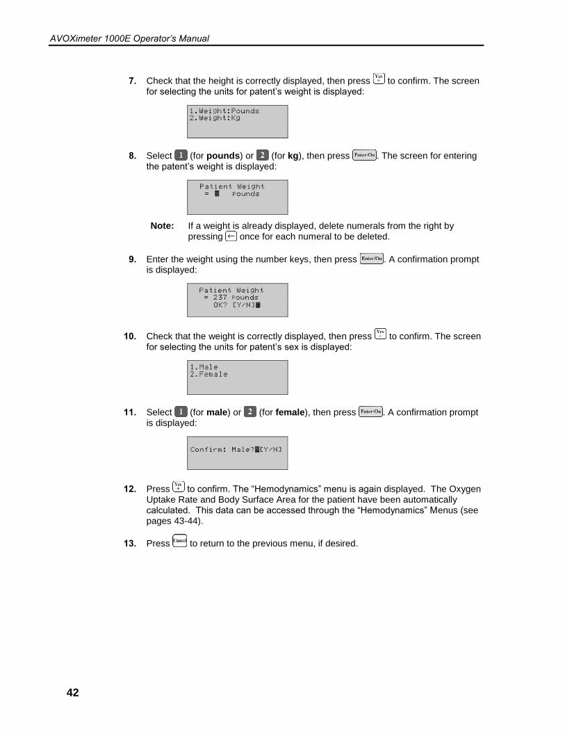
AVOXimeter 1000E Operator’s Manual
42
7. Check that the height is correctly displayed, then press to confirm. The screen for selecting the units for patent’s weight is displayed:
8. Select (for pounds) or (for kg), then press . The screen for entering the patent’s weight is displayed:
Note: If a weight is already displayed, delete numerals from the right by pressing once for each numeral to be deleted.
9. Enter the weight using the number keys, then press . A confirmation prompt is displayed:
10. Check that the weight is correctly displayed, then press to confirm. The screen for selecting the units for patent’s sex is displayed:
11. Select (for male) or (for female), then press . A confirmation prompt is displayed:
12. Press to confirm. The “Hemodynamics” menu is again displayed. The Oxygen Uptake Rate and Body Surface Area for the patient have been automatically calculated. This data can be accessed through the “Hemodynamics” Menus (see pages 43-44).
13. Press to return to the previous menu, if desired.
AVOXimeter 1000E Operator’s Manual
43
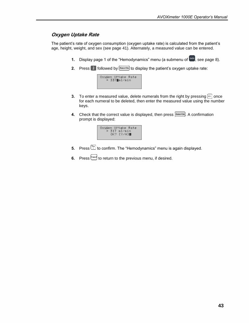
Oxygen Uptake Rate
The patient’s rate of oxygen consumption (oxygen uptake rate) is calculated from the patient’s age, height, weight, and sex (see page 41). Alternately, a measured value can be entered.
1. Display page 1 of the “Hemodynamics” menu (a submenu of , see page 8).
2. Press followed by to display the patient’s oxygen uptake rate:
3. To enter a measured value, delete numerals from the right by pressing once for each numeral to be deleted, then enter the measured value using the number keys.
4. Check that the correct value is displayed, then press . A confirmation prompt is displayed:
5. Press to confirm. The “Hemodynamics” menu is again displayed.
6. Press to return to the previous menu, if desired.
AVOXimeter 1000E Operator’s Manual
44
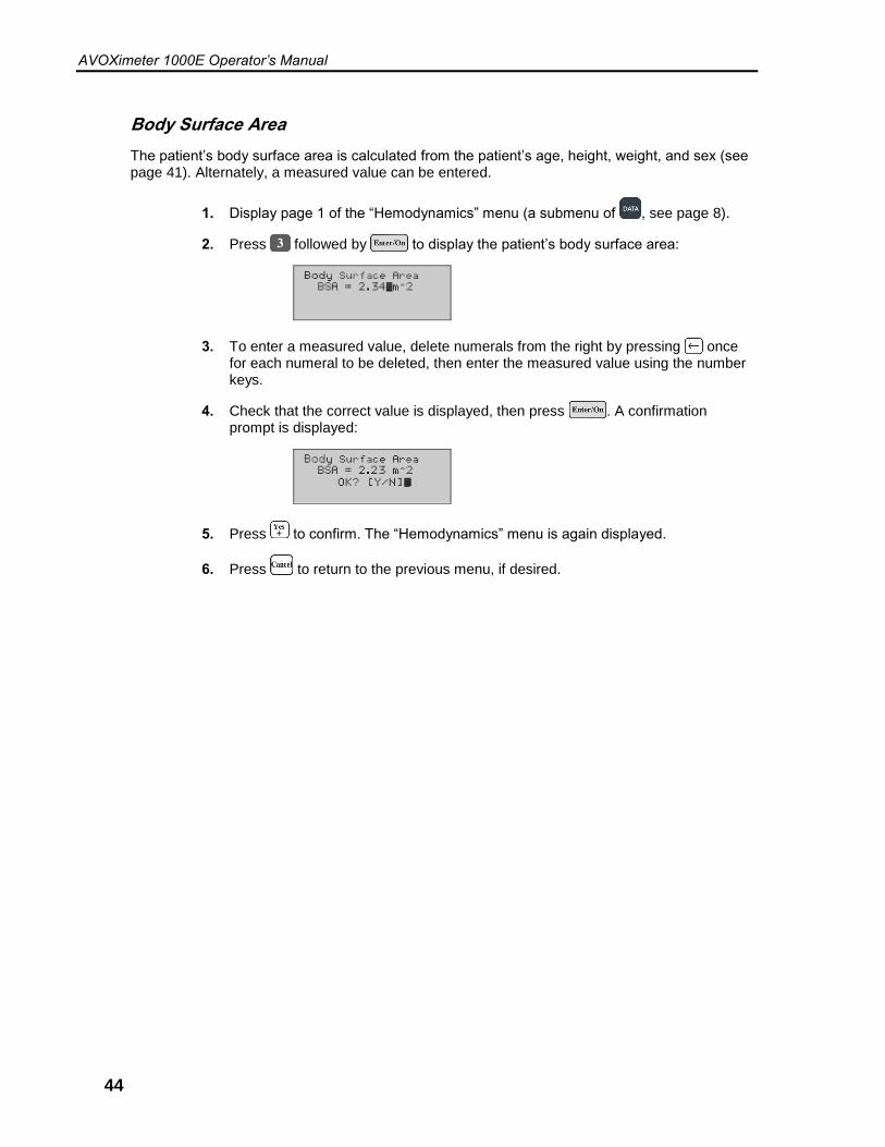
Body Surface Area
The patient’s body surface area is calculated from the patient’s age, height, weight, and sex (see page 41). Alternately, a measured value can be entered.
1. Display page 1 of the “Hemodynamics” menu (a submenu of , see page 8).
2. Press followed by to display the patient’s body surface area:
3. To enter a measured value, delete numerals from the right by pressing once for each numeral to be deleted, then enter the measured value using the number keys.
4. Check that the correct value is displayed, then press . A confirmation prompt is displayed:
5. Press to confirm. The “Hemodynamics” menu is again displayed.
6. Press to return to the previous menu, if desired.

AVOXimeter 1000E Operator’s Manual
45
Saturation Step-Ups
Saturation step-ups are the differences in oxyhemoglobin saturation (%Hb02) between adjacent anatomical sites. These values are used as an aid in diagnosing intracardiac and great vessel shunts.
Important: In order to calculate saturation step-ups for a patient, the AVOXimeter 1000E results for that patient must be labeled with the Patient ID (see page 27) and the anatomical site from which the sample was obtained (see page 23).
The AVOXimeter 1000E uses all measurements stored in the system for a patient when calculating oxyhemoglobin saturation step-ups. The system searches the database for all results for each main oximetry site for that patient, averages the results for each site, and calculates the oxyhemoglobin saturation step-ups from the average result for each main site.
Note: Use of average readings rather than individual values improves the precision of Saturation Step-Up calculations.
1. If needed, enter the Patient ID for which Saturation Step-Ups are to be calculated (see page 27).
2. Display page 1 of the “Hemodynamics” menu (a submenu of , see page 8).
3. Press followed by . The Patient ID for which oxyhemoglobin saturation
step-ups will be calculated is displayed:
4. Verify that the Patient ID is correct, then press . The first page of
oxyhemoglobin saturation step-ups for the patient is displayed:
Note: The following abbreviations are used: RA Right Atrium PA Pulmonary Artery RV Right Ventricle PV Pulmonary Vein LA Left Atrium AO Aorta LV Left Ventricle SVC Superior Vena Cava
5. Press to display the second page of oxyhemoglobin saturation step-ups for the patient:
6. Press when done. The “Hemodynamics” menu is again displayed.
7. Press to return to the previous menu, if desired.
AVOXimeter 1000E Operator’s Manual
46
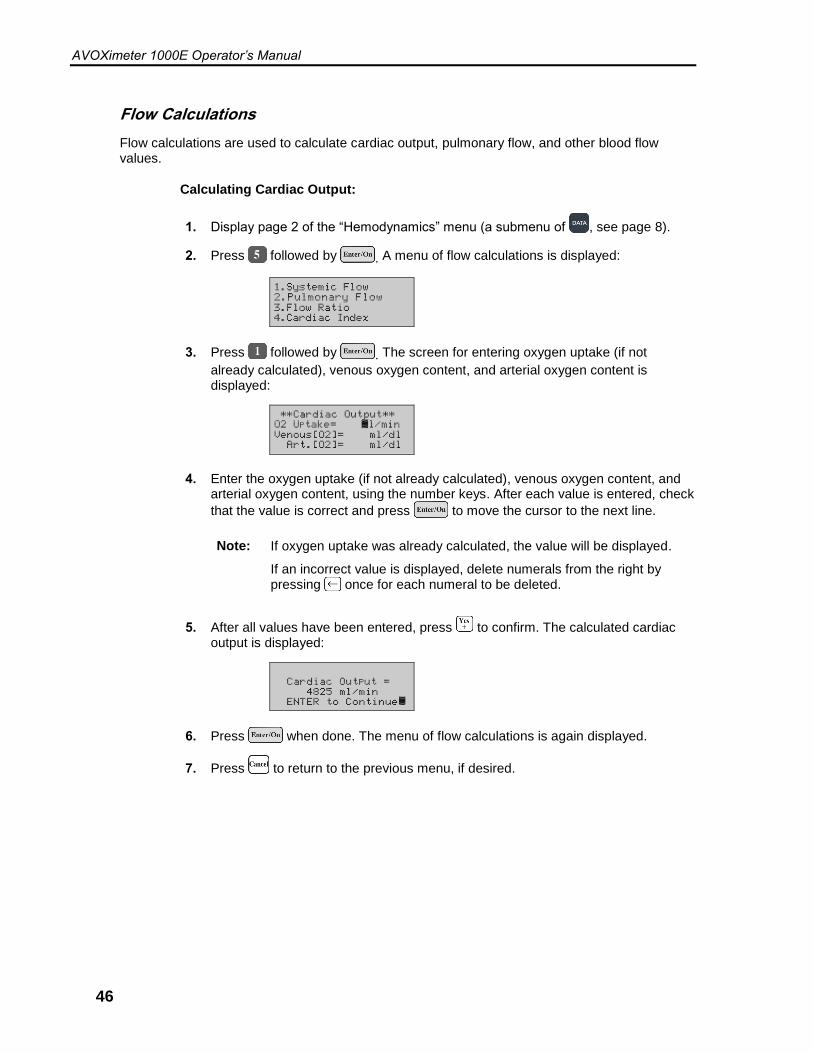
Flow Calculations
Flow calculations are used to calculate cardiac output, pulmonary flow, and other blood flow values.
Calculating Cardiac Output:
1. Display page 2 of the “Hemodynamics” menu (a submenu of , see page 8).
2. Press followed by . A menu of flow calculations is displayed:
3. Press followed by . The screen for entering oxygen uptake (if not
already calculated), venous oxygen content, and arterial oxygen content is displayed:
4. Enter the oxygen uptake (if not already calculated), venous oxygen content, and arterial oxygen content, using the number keys. After each value is entered, check
that the value is correct and press to move the cursor to the next line.
Note: If oxygen uptake was already calculated, the value will be displayed.
If an incorrect value is displayed, delete numerals from the right by pressing once for each numeral to be deleted.
5. After all values have been entered, press to confirm. The calculated cardiac output is displayed:
6. Press when done. The menu of flow calculations is again displayed.
7. Press to return to the previous menu, if desired.
AVOXimeter 1000E Operator’s Manual
47
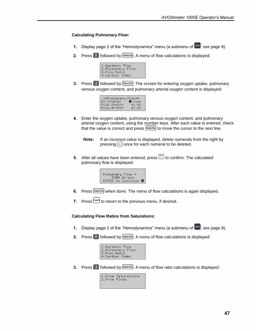
Calculating Pulmonary Flow:
1. Display page 2 of the “Hemodynamics” menu (a submenu of , see page 8).
2. Press followed by . A menu of flow calculations is displayed:
3. Press followed by . The screen for entering oxygen uptake, pulmonary
venous oxygen content, and pulmonary arterial oxygen content is displayed:
4. Enter the oxygen uptake, pulmonary venous oxygen content, and pulmonary arterial oxygen content, using the number keys. After each value is entered, check
that the value is correct and press to move the cursor to the next line.
Note: If an incorrect value is displayed, delete numerals from the right by pressing once for each numeral to be deleted.
5. After all values have been entered, press to confirm. The calculated pulmonary flow is displayed:
6. Press when done. The menu of flow calculations is again displayed.
7. Press to return to the previous menu, if desired.
Calculating Flow Ratios from Saturations:
1. Display page 2 of the “Hemodynamics” menu (a submenu of , see page 8).
2. Press followed by . A menu of flow calculations is displayed:
3. Press followed by . A menu of flow ratio calculations is displayed:
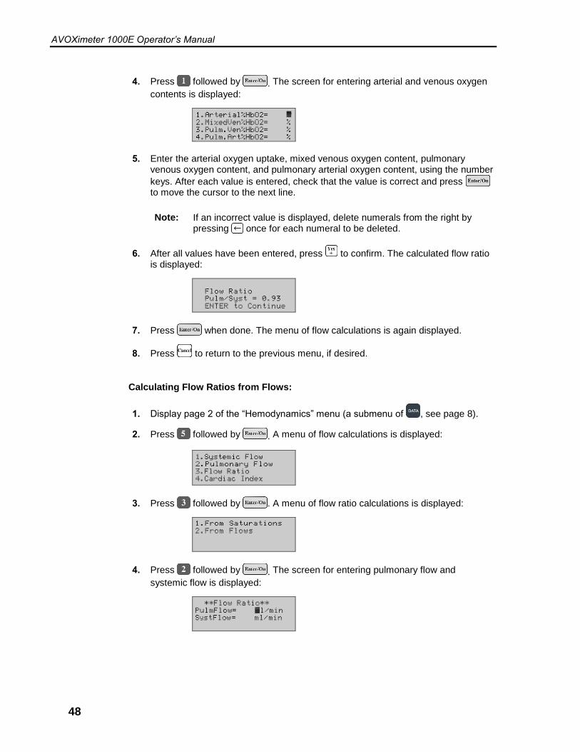
AVOXimeter 1000E Operator’s Manual
48
4. Press followed by . The screen for entering arterial and venous oxygen
contents is displayed:
5. Enter the arterial oxygen uptake, mixed venous oxygen content, pulmonary venous oxygen content, and pulmonary arterial oxygen content, using the number
keys. After each value is entered, check that the value is correct and press to move the cursor to the next line.
Note: If an incorrect value is displayed, delete numerals from the right by pressing once for each numeral to be deleted.
6. After all values have been entered, press to confirm. The calculated flow ratio is displayed:
7. Press when done. The menu of flow calculations is again displayed.
8. Press to return to the previous menu, if desired.
Calculating Flow Ratios from Flows:
1. Display page 2 of the “Hemodynamics” menu (a submenu of , see page 8).
2. Press followed by . A menu of flow calculations is displayed:
3. Press followed by . A menu of flow ratio calculations is displayed:
4. Press followed by . The screen for entering pulmonary flow and
systemic flow is displayed:
AVOXimeter 1000E Operator’s Manual
49
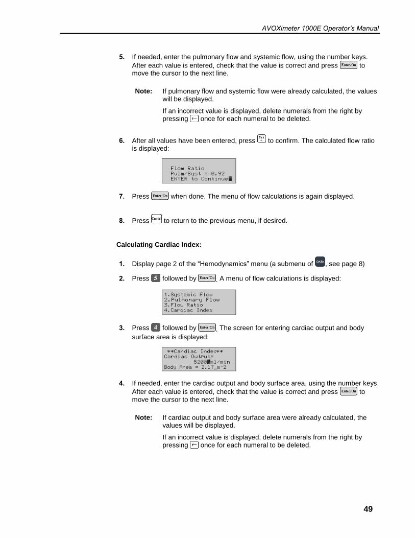
5. If needed, enter the pulmonary flow and systemic flow, using the number keys.
After each value is entered, check that the value is correct and press to move the cursor to the next line.
Note: If pulmonary flow and systemic flow were already calculated, the values will be displayed.
If an incorrect value is displayed, delete numerals from the right by pressing once for each numeral to be deleted.
6. After all values have been entered, press to confirm. The calculated flow ratio is displayed:
7. Press when done. The menu of flow calculations is again displayed.
8. Press to return to the previous menu, if desired.
Calculating Cardiac Index:
1. Display page 2 of the “Hemodynamics” menu (a submenu of , see page 8)
2. Press followed by . A menu of flow calculations is displayed:
3. Press followed by . The screen for entering cardiac output and body
surface area is displayed:
4. If needed, enter the cardiac output and body surface area, using the number keys.
After each value is entered, check that the value is correct and press to move the cursor to the next line.
Note: If cardiac output and body surface area were already calculated, the values will be displayed.
If an incorrect value is displayed, delete numerals from the right by pressing once for each numeral to be deleted.
AVOXimeter 1000E Operator’s Manual
50
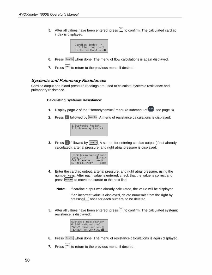
5. After all values have been entered, press to confirm. The calculated cardiac index is displayed:
6. Press when done. The menu of flow calculations is again displayed.
7. Press to return to the previous menu, if desired.
Systemic and Pulmonary Resistances
Cardiac output and blood pressure readings are used to calculate systemic resistance and pulmonary resistance.
Calculating Systemic Resistance:
1. Display page 2 of the “Hemodynamics” menu (a submenu of , see page 8).
2. Press followed by . A menu of resistance calculations is displayed:
3. Press followed by . A screen for entering cardiac output (if not already
calculated), arterial pressure, and right atrial pressure is displayed:
4. Enter the cardiac output, arterial pressure, and right atrial pressure, using the number keys. After each value is entered, check that the value is correct and
press to move the cursor to the next line.
Note: If cardiac output was already calculated, the value will be displayed.
If an incorrect value is displayed, delete numerals from the right by pressing once for each numeral to be deleted.
5. After all values have been entered, press to confirm. The calculated systemic resistance is displayed:
6. Press when done. The menu of resistance calculations is again displayed.
7. Press to return to the previous menu, if desired.

AVOXimeter 1000E Operator’s Manual
51
Calculating Pulmonary Resistance:
1. Display page 2 of the “Hemodynamics” menu (a submenu of , see page 8).
2. Press followed by . A menu of resistance calculations is displayed:
3. Press followed by . A screen for entering cardiac output (if not already
calculated), pulmonary artery pressure, and left atrial pressure is displayed:
4. Enter the cardiac output, pulmonary artery pressure, and left atrial pressure, using the number keys. After each value is entered, check that the value is correct and
press to move the cursor to the next line.
Note: If cardiac output was already calculated, the value will be displayed.
If an incorrect value is displayed, delete numerals from the right by pressing once for each numeral to be deleted.
5. After all values have been entered, press to confirm. The calculated pulmonary resistance is displayed:
6. Press when done. The menu of resistance calculations is again displayed.
7. Press to return to the previous menu, if desired.

AVOXimeter 1000E Operator’s Manual
52
Stroke Volume and Stroke Index Cardiac output and heart rate measurements are used to calculate the stroke volume (the volume of blood ejected from a ventricle at each beat of the heart). Stroke Index is the stroke volume normalized for body mass.
Calculating Stroke Volume:
1. Display page 2 of the “Hemodynamics” menu (a submenu of , see page 8).
2. Press followed by . A menu of stroke calculations is displayed:
3. Press followed by . A screen for entering cardiac output (if not already
calculated) and heart rate is displayed:
4. Enter the cardiac output and heart rate, using the number keys. After each value
is entered, check that the value is correct and press to move the cursor to the next line.
Note: If cardiac output was already calculated, the value will be displayed.
If an incorrect value is displayed, delete numerals from the right by pressing once for each numeral to be deleted.
5. After all values have been entered, press to confirm. The calculated stroke volume is displayed:
6. Press when done. The menu of stroke calculations is again displayed.
7. Press to return to the previous menu, if desired.
AVOXimeter 1000E Operator’s Manual
53
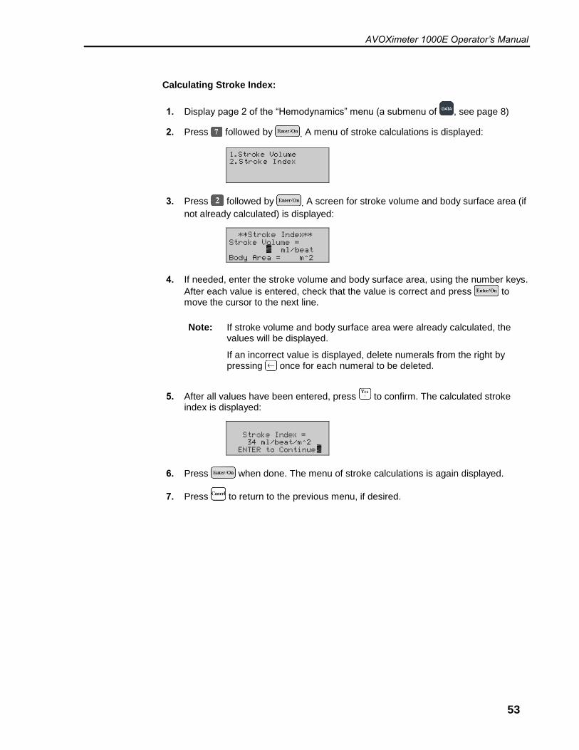
Calculating Stroke Index:
1. Display page 2 of the “Hemodynamics” menu (a submenu of , see page 8)
2. Press followed by . A menu of stroke calculations is displayed:
3. Press followed by . A screen for stroke volume and body surface area (if
not already calculated) is displayed:
4. If needed, enter the stroke volume and body surface area, using the number keys.
After each value is entered, check that the value is correct and press to move the cursor to the next line.
Note: If stroke volume and body surface area were already calculated, the values will be displayed.
If an incorrect value is displayed, delete numerals from the right by pressing once for each numeral to be deleted.
5. After all values have been entered, press to confirm. The calculated stroke index is displayed:
6. Press when done. The menu of stroke calculations is again displayed.
7. Press to return to the previous menu, if desired.
AVOXimeter 1000E Operator’s Manual
54
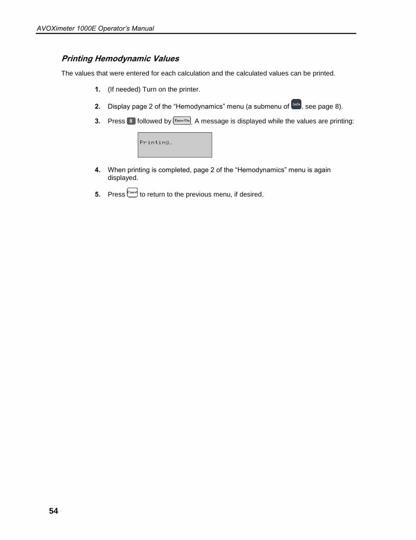
Printing Hemodynamic Values
The values that were entered for each calculation and the calculated values can be printed.
1. (If needed) Turn on the printer.
2. Display page 2 of the “Hemodynamics” menu (a submenu of , see page 8).
3. Press followed by . A message is displayed while the values are printing:
4. When printing is completed, page 2 of the “Hemodynamics” menu is again displayed.
5. Press to return to the previous menu, if desired.

AVOXimeter 1000E Operator’s Manual
55
Troubleshooting
Symptom Possible Cause Action Required
The instrument does not turn on.
1. The AC Adapter is not connected to an AC outlet and/or the instrument, and the battery is discharged.
1. Connect the AC Adapter to an AC outlet and the AVOXimeter 1000E.
The instrument does not respond to keystrokes or cuvette insertion.
1. The microprocessor is locked up.
1. Press the and keys simultaneously to turn the instrument off, then turn the instrument back on.
2. If this fails, contact Technical Support (see page ii).
Self-Test fails on power-up. The following error message is displayed:
"Cuvette Inserted???"
1. A cuvette is inserted in the instrument. If a cuvette is not inserted in the instrument, see #2 below:
1. Remove cuvette, turn unit off and restart.
2. Intensities are out of range.
2. At "Cuvette Inserted???"
screen, press twice for Diagnostic Mode. Press any
key and then press to re-adjust light sources. When program finishes, turn the instrument off and then on.
3. The cable from the detector to the circuit board is disconnected.
3. Open the case and check that the cables are properly connected.
4. There is no power to the LEDs. The LED cable may be loose, disconnected or improperly placed on the connector at one or both ends.
4. Open the case and check that the cables are properly connected.
5. One or more LEDs is defective.
5. Contact Technical Support (see page ii).
The external printer is not printing.
1. There is no power to the printer.
1. Connect the printer to an AC outlet and turn on the printer.
2. The printer is not connected to the instrument.
2. Connect the printer to the AVOXimeter 1000E (see page 10).
3. The wrong print mode, baud rate, or parity is selected.
3. Specify the proper values for the printer (see page 30).
4. The microprocessor is locked up.
4. See above.

AVOXimeter 1000E Operator’s Manual
56
Symptom Possible Cause Action Required
Measurements of %HbO2 are not accurate
1. The optical detector may be contaminated by blood or foreign material.
1. Run optical quality control. If needed, clean the optical detector (see page 59).
2. The instrument may require calibration.
2. Re-calibrate the instrument (see page 39).
Measurements of THb are not accurate
1. The wrong cuvette pathlength is entered into the instrument.
1. Obtain the correct cuvette pathlength value from the cuvette carton and enter the value (see page 39).
2. The optical detector may be contaminated by blood or foreign material.
2. Clean the optical detector (see page 59).
3. The instrument may require calibration.
3. Re-calibrate the instrument (see page 39).
Calculated Pulmonary-to-Systemic Flow Ratio is a negative number or otherwise not believable.
1. Equal values were entered for Pulm. Venous and Pulm. Arterial %HbO2.
1. Obtain correct values for Pulm. Venous and/or Pulm. Arterial %HbO2.
2. An incorrect entry was made for one of the entered quantities.
2. Review and, if necessary, re-enter correct values.
One of the following ERROR: messages is displayed:
“%HbO2<> XX.X%“ or
“%HbCO<> XX.X%“ or
“%HbMet<> XX.X%“ or
“%RHb<> XX.X%“
1. A cuvette without a sample was inserted.
2. The cuvette was not properly filled.
3. The optical detector may be contaminated by blood or foreign material.
1. Test a new cuvette that contains the sample.
2. Ensure that the sample reaches the vent patch when filling and that there are no air bubbles in the optical window.
3. Run optical quality control. If needed, clean the optical detector (see page 59).
4. LED intensities are too low. 4. Remove cuvette, turn unit off, and restart. Verify that the self test passes.
5. The sample is lipemic. 5. If possible, obtain a replacement sample that is not lipemic.
The following ERROR: message is displayed:
“THb < 4.0 g/dL“
1. THb may actually be low. In this case, values of THb and %HbO2 not likely to be accurate.
1. Contact Technical Support (see page ii).
The following ERROR: message is displayed:
“THb > 25.0 g/dL“
1. THb may actually be high. In this case, values of THb and %HbO2 not likely to be accurate.
1. Contact Technical Support (see page ii).

AVOXimeter 1000E Operator’s Manual
57
Symptom Possible Cause Action Required
THb and/or %HbO2 readings for yellow or orange filter are out of range.
1. The optical detector may be contaminated by blood or foreign material.
1. Clean the optical detector (see page 59).
2. The instrument may require calibration.
2. Re-calibrate the instrument (see page 39).
The following ERROR: message is displayed:
“Uninitialized Vector Service Required“
1. Microprocessor error. 1. Press the and keys simultaneously to turn the instrument off, then turn the instrument back on.
2. If the problem persists, contact Technical Support (see page ii).

AVOXimeter 1000E Operator’s Manual
58
This page was left intentionally blank.
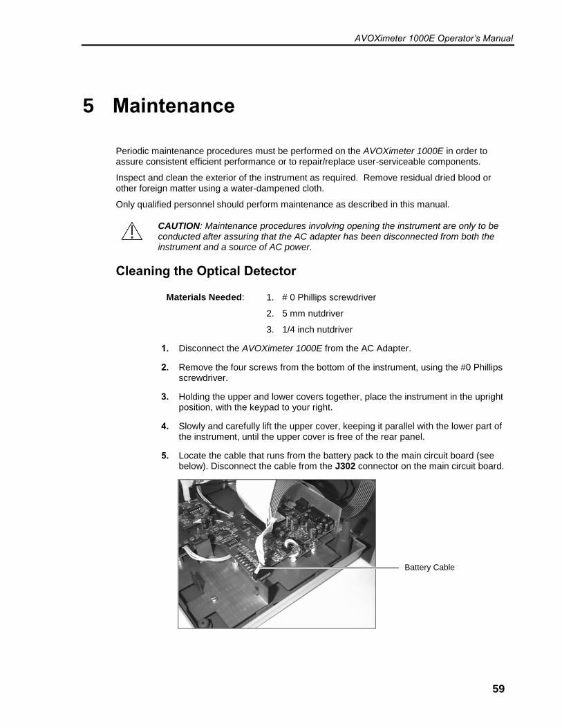
AVOXimeter 1000E Operator’s Manual
59
5 Maintenance
Periodic maintenance procedures must be performed on the AVOXimeter 1000E in order to assure consistent efficient performance or to repair/replace user-serviceable components.
Inspect and clean the exterior of the instrument as required. Remove residual dried blood or other foreign matter using a water-dampened cloth.
Only qualified personnel should perform maintenance as described in this manual.
CAUTION: Maintenance procedures involving opening the instrument are only to be conducted after assuring that the AC adapter has been disconnected from both the instrument and a source of AC power.
Cleaning the Optical Detector
Materials Needed: 1. # 0 Phillips screwdriver
2. 5 mm nutdriver
3. 1/4 inch nutdriver
1. Disconnect the AVOXimeter 1000E from the AC Adapter.
2. Remove the four screws from the bottom of the instrument, using the #0 Phillips screwdriver.
3. Holding the upper and lower covers together, place the instrument in the upright position, with the keypad to your right.
4. Slowly and carefully lift the upper cover, keeping it parallel with the lower part of the instrument, until the upper cover is free of the rear panel.
5. Locate the cable that runs from the battery pack to the main circuit board (see below). Disconnect the cable from the J302 connector on the main circuit board.
Battery Cable
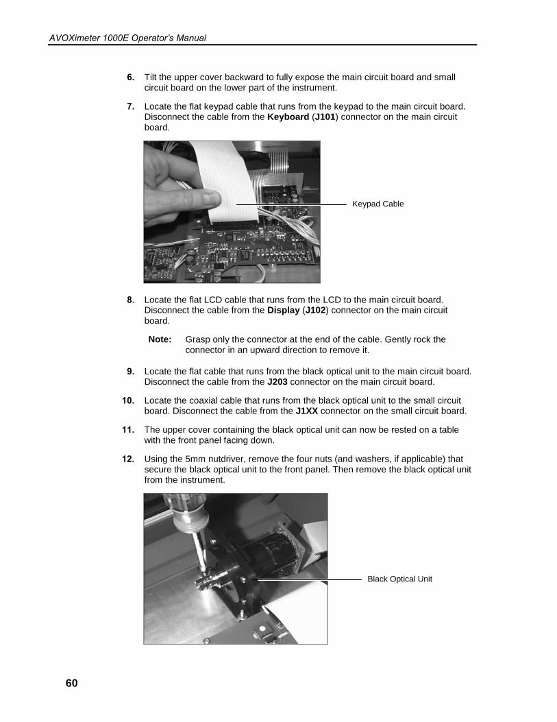
AVOXimeter 1000E Operator’s Manual
60
6. Tilt the upper cover backward to fully expose the main circuit board and small circuit board on the lower part of the instrument.
7. Locate the flat keypad cable that runs from the keypad to the main circuit board. Disconnect the cable from the Keyboard (J101) connector on the main circuit board.
8. Locate the flat LCD cable that runs from the LCD to the main circuit board. Disconnect the cable from the Display (J102) connector on the main circuit board.
Note: Grasp only the connector at the end of the cable. Gently rock the connector in an upward direction to remove it.
9. Locate the flat cable that runs from the black optical unit to the main circuit board. Disconnect the cable from the J203 connector on the main circuit board.
10. Locate the coaxial cable that runs from the black optical unit to the small circuit board. Disconnect the cable from the J1XX connector on the small circuit board.
11. The upper cover containing the black optical unit can now be rested on a table with the front panel facing down.
12. Using the 5mm nutdriver, remove the four nuts (and washers, if applicable) that secure the black optical unit to the front panel. Then remove the black optical unit from the instrument.
Keypad Cable
Black Optical Unit

AVOXimeter 1000E Operator’s Manual
61
13. Using the 1/4" nutdriver, remove the four screws and four nuts that secure the two halves of the black optical unit. Take care when separating the two halves of the optical unit. Do not lose the small torsion spring or the shutter door. Set them aside in a safe place for reassembly.
14. Clean the exposed detector with gauze pads dampened with detergent. Do not use abrasives. Then dry off the detector surface, making sure that it is clean. Remove any other debris inside the optical unit.
15. Reassemble the two halves of the optical unit, making sure that the Shutter Door (AV6400) and Torsion Spring (AV6600) are installed correctly (the two door ribs will face outward). One leg of the spring fits into a hole in the door slot, the other leg rests behind the shutter door. Bolt the optical unit back together.
Black Optical Unit
Short End of Torsion Spring
Long End of Torsion Spring
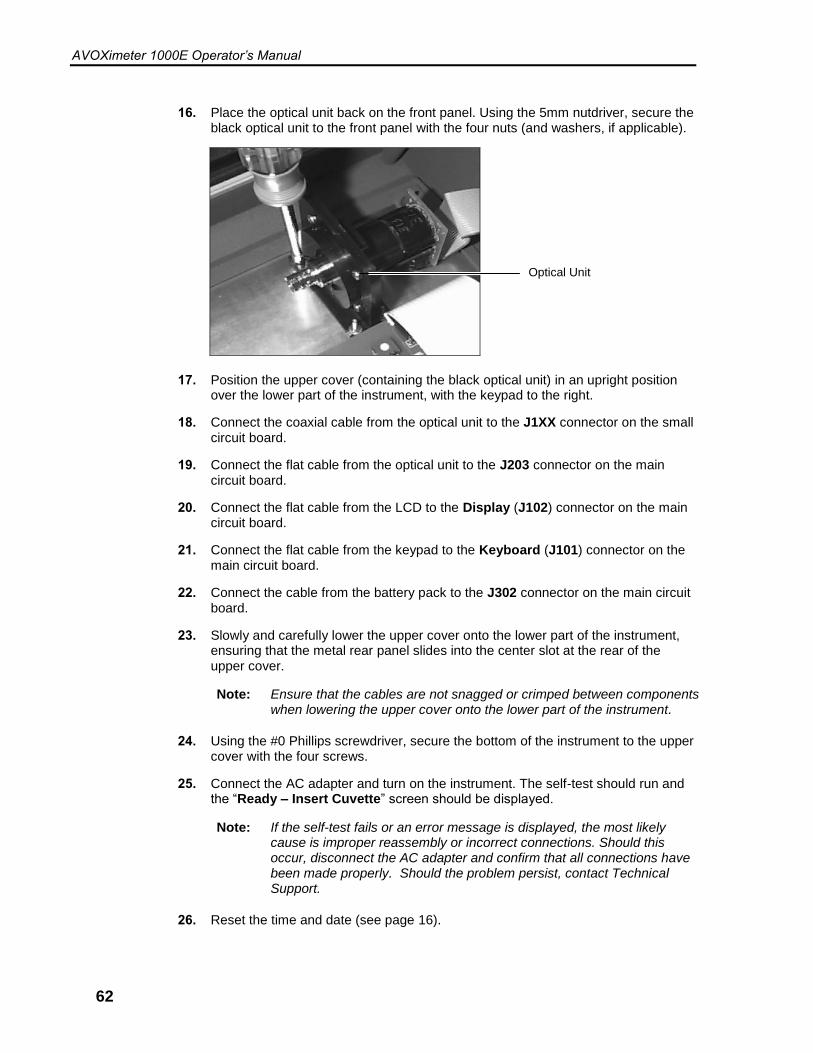
AVOXimeter 1000E Operator’s Manual
62
16. Place the optical unit back on the front panel. Using the 5mm nutdriver, secure the black optical unit to the front panel with the four nuts (and washers, if applicable).
17. Position the upper cover (containing the black optical unit) in an upright position over the lower part of the instrument, with the keypad to the right.
18. Connect the coaxial cable from the optical unit to the J1XX connector on the small circuit board.
19. Connect the flat cable from the optical unit to the J203 connector on the main circuit board.
20. Connect the flat cable from the LCD to the Display (J102) connector on the main circuit board.
21. Connect the flat cable from the keypad to the Keyboard (J101) connector on the main circuit board.
22. Connect the cable from the battery pack to the J302 connector on the main circuit board.
23. Slowly and carefully lower the upper cover onto the lower part of the instrument, ensuring that the metal rear panel slides into the center slot at the rear of the upper cover.
Note: Ensure that the cables are not snagged or crimped between components when lowering the upper cover onto the lower part of the instrument.
24. Using the #0 Phillips screwdriver, secure the bottom of the instrument to the upper cover with the four screws.
25. Connect the AC adapter and turn on the instrument. The self-test should run and the “Ready – Insert Cuvette” screen should be displayed.
Note: If the self-test fails or an error message is displayed, the most likely cause is improper reassembly or incorrect connections. Should this occur, disconnect the AC adapter and confirm that all connections have been made properly. Should the problem persist, contact Technical Support.
26. Reset the time and date (see page 16).
Optical Unit

AVOXimeter 1000E Operator’s Manual
63
Replacing the Battery
Materials Needed: 1. # 0 Phillips screwdriver
2. Diagonal cutting pliers
3. Replacement battery with cable (E4-BATP-2)
4. Securing cording (packaged with replacement battery)
1. Steps 1 through 11 of the Cleaning the Optical Detector procedure on page 59 Must be performed before moving to step 2 of “Replacing the Battery”, below.
Note: The battery is housed in the lower cover.
2. Using the diagonal cutting pliers, cut the plastic ties that secure the battery to the frame.
Note: Be sure to cut only the white plastic ties that are wrapped around the battery and secure it to the lower cover. Do not cut the blue and white power cables that are connected to the top of the battery.
3. Remove the battery, being careful not to snag any components when pulling the cable out from underneath the main circuit board. If the battery well contains tape, remove the tape.
4. Remove the liner from the tape on the bottom of the new battery, and place the new battery in the battery well with the tape side down, ensuring that the blue and white cables are facing up, then route the new plastic ties (packaged with the replacement battery) underneath the battery well.
Plastic Tie
Plastic Tie
Blue and White Battery Cable
New Plastic Tie
New Battery
New Plastic Tie

AVOXimeter 1000E Operator’s Manual
64
5. Secure the new battery in the battery well, using the new white plastic ties.
Note: When securing the battery to the battery well, be sure that the plastic ties are routed underneath the battery well. Cut the excess length from the plastic ties using the diagonal cutting pliers.
6. Thread the blue and white battery cable of the new battery under the main circuit board.
7. Re-connect the cables, replace the upper cover of the AVOXimeter 1000E, connect the AC adapter, and turn on the instrument as outlined in Steps 17 through 25 of the Cleaning the Optical Detector procedure on page 59. The self-test should run and the “Ready – Insert Cuvette” screen should be displayed.
Note: Be sure to connect the blue and white battery cable last.
The new battery is not charged. To ensure adequate charge, leave the instrument connected to the AC Adapter for a minimum of eight hours. Tests can be run while the instrument is charging.
8. Reset the time and date (see page 16).

AVOXimeter 1000E Operator’s Manual
65
6 Quality Control Logs
Quality control logs for the yellow and orange filters and liquid control levels 1, 2, and 3 are shown on the following pages.
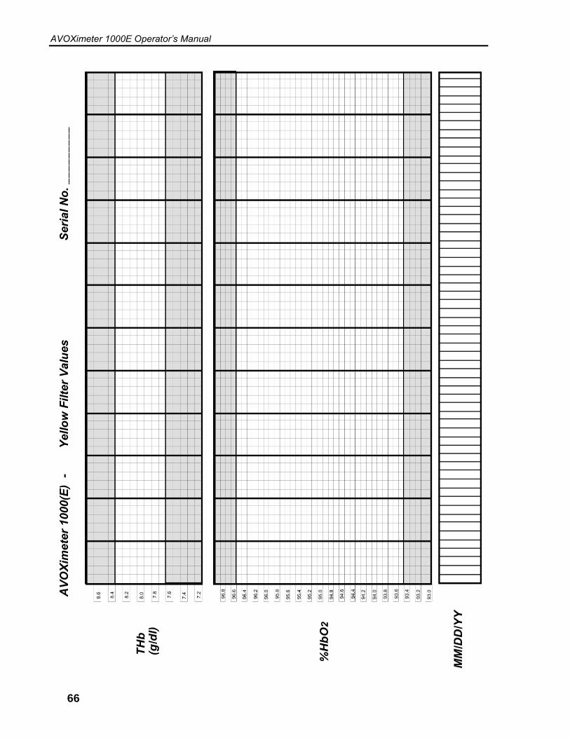
AVOXimeter 1000E Operator’s Manual
66

AVOXimeter 1000E Operator’s Manual
67

AVOXimeter 1000E Operator’s Manual
68
7 Warranty
Certification, Warranty and Service Warranty, and Service
Accriva, declares to the original purchaser that each instrument manufactured and sold by Accriva, or sold by an authorized dealer, shall be free from defects in material and workmanship and, under normal and proper use conditions, warrants it for a period of one year from installation and no more than 13 months from the shipping date, except as otherwise provided in writing.
Accriva's obligation is limited to repairing, replacing, or modifying (at Accriva’s undisputed judgment) at Accriva's factory, or elsewhere, the material whose defects have been verified, on condition that the purchaser has informed Accriva of any defects found within 15 days from receipt. Damages caused by or connected to transport are excluded. Transport to and from our facility will be at purchaser’s charge and risk, and shall also be prepaid for reshipment, except as otherwise provided in writing. These replacements, repairs, or alterations will in no case determine extension to the above specified warranty period.
The warranty does not cover those parts that deteriorate, or which are in any case considered consumables, or those parts or “items”, which by their nature are normally required to be replaced periodically consistent with normal maintenance. It is also understood that, following the purchase and delivery of the instrument, the purchaser shall be deemed liable for any losses, damages, or complaints concerning persons or things incurred by the use, or misuse of the instrument, on behalf of the purchaser, its employees, co-operators, or others. Accriva does not assume any obligation or warranty engagement concerning precision and/or accuracy of the measurements, as well as for any damage to the instrument, directly or indirectly resulting from the use of reagents and/or consumables different from those produced by Accriva specifically for its own instruments, and for the same properly tested.
Warranty will not apply to those defective instruments or materials showing defects or damage arising from the following causes:
1. Insufficient or negligent care by the purchaser.
2. Insufficient or negligent maintenance by the purchaser in relation to the instructions contained in the manuals prepared by Accriva for this purpose; tampering or alterations of the instruments, or in any case interventions or repairs made by any person not duly authorized by Accriva.
3. Misuse due to carelessness, negligence, or inexperience.
4. Employment of materials under heavier conditions than those for which they have been designed and manufactured, and use of the same in combination with incompatible or dangerous products.
5. Non-observance of the regulations relevant to installation, power supply, and operation of the instruments (with particular regard to the regulations for accident prevention).

AVOXimeter 1000E Operator’s Manual
69
THIS WARRANTY IS GIVEN EXPRESSLY AND IN LIEU OF ALL OTHER WARRANTIES, EXPRESS OR IMPLIED. PURCHASER AGREES THAT THERE IS NO WARRANTY OR MERCHANTABILITY AND THAT THERE ARE NO OTHER REMEDIES OR WARRANTIES, EXPRESS OR IMPLIED, WHICH EXTEND BEYOND THE CONTENTS OF THIS AGREEMENT.
No agent or employee of Accriva is authorized to extend any other warranty or to assume for Accriva any liability except as above set forth.
Please contact Technical Support if any malfunction is discovered.

AVOXimeter 1000E Operator’s Manual
70
8 Safety Standards
The AVOXimeter 1000E instrument complies with the following safety standard requirements and directives:
CAN/CSA C22.2 No. 61010-1:2012 CAN/CSA C22.2 No. 61010-2-101:2009 CAN/CSA C22.2 No. 61010-2-010:2009
UL 61010-1:2012
IEC/EN 61010-1:2010 IEC/EN 61010-2-101:2002 IEC/EN 61010-2-010:2003
EN 55011:2009 A1:2010 EN 61326-1:2006
Group 1 Class A Class A limit
This instrument has been designed and tested to CISPR 11 Class A. In a domestic environment it may cause radio interference, in which case, you may need to take measures to mitigate the interference. It is Accriva’s responsibility to provide electromagnetic compatibility information to the customer or users. It is the user’s responsibility to insure that a compatible electromagnetic environment for the instrument can be maintained in the order that the device will perform as intended. EN 61326-1:2006 Table 2 limits
CAUTION: Do not use this instrument in close proximity to sources of strong electromagnetic radiation (e.g. unshielded intentional RF sources), as these may interfere with proper operation.
Protection against ingress of liquids: Ordinary (no protection as defined by IEC 60529)
Product cleaning and disinfection: Only according to recommendations of the manufacturer’s accompanying documentation
Mode of operation of equipment: Continuous
Degree of safety of application in the presence of flammable anesthetic mixture with air, oxygen or nitrous oxide: Not Suitable.
Note:
As defined in the above standards, the classification of “Not Suitable” DOES NOT MEAN that the instrument is not suitable for use in an Operating Room (OR) environment. Rather, it is intended to indicate that the instrument is not suitable for use in the direct presence of a flammable anesthetic mixture with air, oxygen or nitrous oxide.
All relevant documentation is kept on file at Accriva Diagnostics, Inc., San Diego, CA.
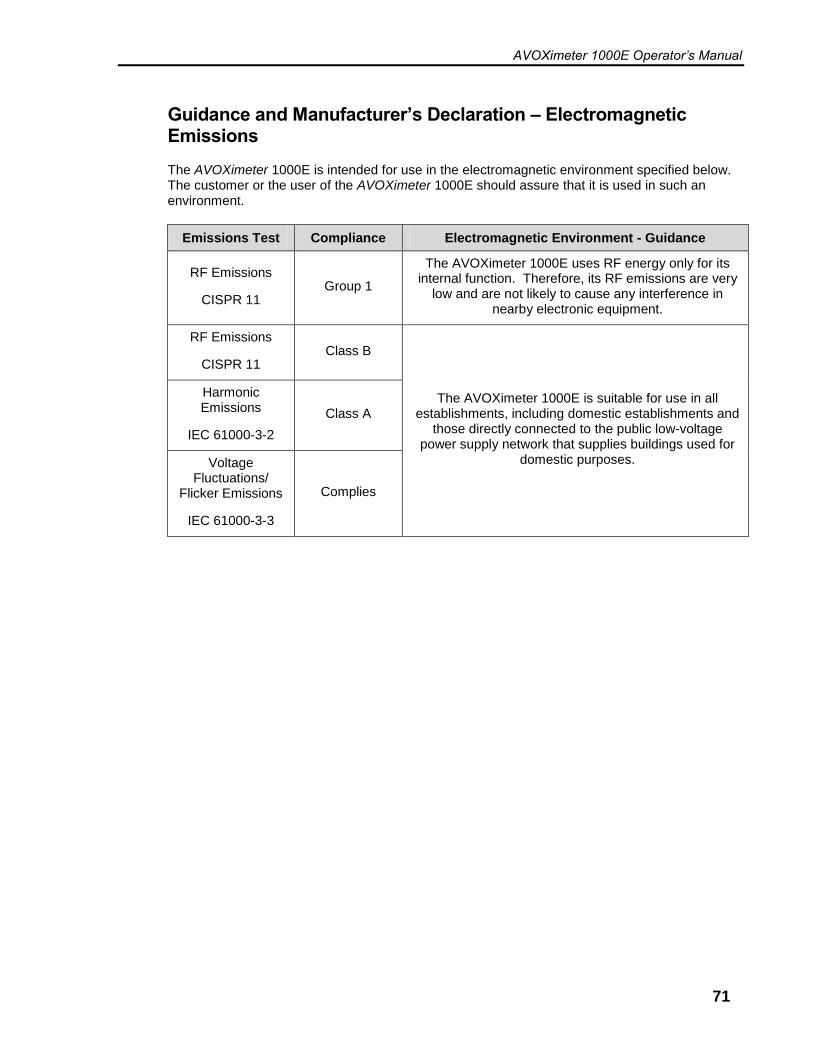
AVOXimeter 1000E Operator’s Manual
71
Guidance and Manufacturer’s Declaration – Electromagnetic Emissions
The AVOXimeter 1000E is intended for use in the electromagnetic environment specified below. The customer or the user of the AVOXimeter 1000E should assure that it is used in such an environment.
Emissions Test Compliance Electromagnetic Environment - Guidance
RF Emissions
CISPR 11 Group 1
The AVOXimeter 1000E uses RF energy only for its internal function. Therefore, its RF emissions are very
low and are not likely to cause any interference in nearby electronic equipment.
RF Emissions
CISPR 11 Class B
The AVOXimeter 1000E is suitable for use in all establishments, including domestic establishments and
those directly connected to the public low-voltage power supply network that supplies buildings used for
domestic purposes.
Harmonic Emissions
IEC 61000-3-2
Class A
Voltage Fluctuations/
Flicker Emissions
IEC 61000-3-3
Complies

AVOXimeter 1000E Operator’s Manual
72
Guidance and Manufacturer’s Declaration – Electromagnetic Immunity
The AVOXimeter 1000E is intended for use in the electromagnetic environment specified below. The customer or the user of the AVOXimeter System should assure that it is used in such an environment.
Immunity Test IEC 60601 Test Level
Compliance Level
Electromagnetic Environment - Guidance
Electrostatic Discharge (ESD)
IEC 61000-4-2
+ 6 kV contact
+ 8 kV air
+ 6 kV contact
+ 8 kV air
Floors should be wood, concrete or ceramic tile. If floors are covered with synthetic material, the relative humidity
should be at least 30 %.
Electrical fast transient / Burst
IEC 61000-4-4
+ 2 kV for power supply
lines
+1 kV for input/output
lines
+ 2 kV for power supply
lines
+1 kV for input/output
lines
Mains power quality should be that of a typical domestic, commercial or
hospital environment.
Surge
IEC 61000-4-5
+1 kV differential
mode
+2 kV common
mode
+1 kV differential
mode
+2 kV common mode
Mains power quality should be that of a typical domestic, commercial or
hospital environment.
Voltage dips, short interruptions, and voltage variations on power supply
input lines
IEC 61000-4-11
<5 % UT
(>95 % dip in UT for 0.5
cycle)
40 % UT
(60 % dip in UT) for 5
cycles
70 % UT
(30 % dip in UT) for 25
cycles
<5 % UT
(>95 % dip in UT) for 5 sec
<5 % UT
(>95 % dip in UT for 0.5
cycle)
40 % UT
(60 % dip in UT) for 5 cycles
70 % UT
(30 % dip in UT) for 25
cycles
<5 % UT
(>95 % dip in UT) for 5 sec
Mains power quality should be that of a typical domestic, commercial or
hospital environment.
If the user of the AVOXimeter 1000E requires continued operations during
power mains interruptions, it is recommended that the AVOXimeter
1000E be powered from an uninterruptible power supply or battery.
Power frequency (50/60 Hz)
magnetic field
IEC 61000-4-8
3 A/m 3 A/m
Power frequency magnetic fields should be at levels characteristic of a typical location in a typical domestic, commercial or hospital environment.
AVOXimeter 1000E Operator’s Manual
73
Index
backlighting ...................................................... 15 batteries
charging ....................................................... 14 checking ....................................................... 14
calculations .............................................. 1, 2, 41 calibration .................................................. 12, 39 changing
date and time ............................................... 16 units for total hemoglobin ............................. 15
connections ...................................................... 10 cuvettes ............................................................. 9
handling ........................................................ 29 pathlength .................................................... 39
data management ........................................ 1, 31 display panel ...................................................... 6 handling
cuvettes .......................................................... 9 hemodynamic calculations .............................. 41
body surface area ........................................ 44 flow ............................................................... 46 oxygen uptake rate ...................................... 43 pulmonary resistance ................................... 51 stroke index .................................................. 53 stroke volume ............................................... 52 systemic resistance ...................................... 50
Hüfner’s number ........................................ 12, 25 instrument
calibration ............................................... 12, 39 connections .................................................. 10 customization ................................................. 1 description ...................................................... 6 front panel ...................................................... 6 keypad ............................................................ 7 limitations ....................................................... 5 lockout .......................................................... 10 maintenance ................................................. 59 menus ............................................................ 8 precautions and warnings .............................. 5 safety standards ........................................... 70 setup ............................................................ 15 shutdown ................................................ 10, 40 specifications ................................................ 11 standby ......................................................... 10 startup .......................................................... 27 unpacking and inspection ............................ 13 warranty ....................................................... 68
intended use ...................................................... 1 keypad ............................................................... 7 labels and symbols ............................................ vi
limitations ...........................................................5 liquid controls .................................................. 35
entering lot numbers .................................... 36 tagging a test with lot number ...................... 37
lockout ............................................................. 10 menus .................................................................8 optical detector
cleaning........................................................ 59 optical quality control ....................................... 34 oximetry sites
specifying ..................................................... 23 patient ID
entering ........................................................ 27 requiring ................................................. 18, 22
precautions .........................................................5 printer ........................................................ 10, 30
connection ................................................... 30 printing
aborting ........................................................ 33 any sample .................................................. 32 hemodynamic values ................................... 54 last sample ................................................... 32 QC data........................................................ 31 stored data ................................................... 31
purging test records ......................................... 33 QA user ID
changing ...................................................... 21 QC lockout ....................................................... 38 quality control logs ........................................... 65 running a test ................................................... 29 safety standards .............................................. 70 sample preparation .............................................1 saturation step-ups ...................................... 3, 45 setting
patient ID required ....................................... 18 standby delay ............................................... 17 user ID required ........................................... 18
shutdown ................................................... 10, 40 specifications ................................................... 11 standby ............................................................ 10 summary and explanation ..................................1 symbols ............................................................. vi test cuvettes .......................................................9 tests
running ......................................................... 29 troubleshooting ................................................ 55 unpacking and inspection ................................ 13 user ID
adding .......................................................... 19

AVOXimeter Operator’s Manual
74
deleting ......................................................... 19 entering ........................................................ 27 printing list .................................................... 20
requiring ....................................................... 18 warnings ............................................................ 5 warranty ........................................................... 68

AVOXimeter 1000E Operator’s Manual
75
This page was left intentionally blank.

AVOXimeter Operator’s Manual
76
This page was left intentionally blank.

AVOXimeter 1000E Operator’s Manual
77
This page was left intentionally blank.

AVOXimeter Operator’s Manual
78
AP1001EN 0515