itc engineering services, inc. · test report issued under the responsibility of: itc engineering...
TRANSCRIPT

Test Report issued under the responsibility of:
ITC ENGINEERING SERVICES, INC.
IEC 61000-6-4: 2011, Electromagnetic Compatibility (EMI)
– Generic Standards – Emission Standard for Industrial Environments
IEC 61000-6-2: 2016, Electromagnetic Compatibility (EMC) – Generic Standards –
Immunity Standard for Industrial Environments
Report Reference No. ................ : 20170501-02_CE
Date of Issue ............................... : June 5, 2017
Total Number of Pages ............... : 38
Testing Laboratory .................... : ITC Engineering Services, Inc.
Address ....................................... : 9959 Calaveras Road, Box 543, Sunol CA 94586
Applicant’s Name ...................... : Techniquip
Address ....................................... : 530 Boulder Ct. # 103 Place Pleasanton, CA 94588
Contact ........................................ : Mr. David Wensley
Phone .......................................... : 925-251-9036
Test Specification Standard ....... : See Report for Details
Test Procedure ............................ : Emissions & Immunity
Judgment..................................... : Complies as Tested
Manufacturer Logo ..................... :
Manufacturer .............................. : Techniquip
Model/Type Reference ............... : PROLUX
Input Voltage Rating ................... : 100-240V, 50/60Hz
ISO/IEC 17025: 2005 Accredited Laboratory
6/05/17
Prepared By: ITC Engineering Services, Inc. 9959 Calaveras Road, PO Box 543 Sunol, California 94586-0543 Tel: +1(925) 862-2944 Fax: +1(925) 862-9013 Email: [email protected] Web: www.itcemc.com
Page 2 of 38
Product: ProLux LED ILLUMINATOR
TABLE OF CONTENTS TABLE OF CONTENTS .............................................................................................................................................................. 2
1.1 TESTING LOCATION ..................................................................................................................................................... 4 1.2 REVISION HISTORY ...................................................................................................................................................... 4 1.3 SUMMARY OF TESTS .................................................................................................................................................... 5 1.4 DECLARATION/DISCLAIMER ........................................................................................................................................ 5 1.5 CONDITION OF EUT ..................................................................................................................................................... 5 1.6 GENERAL DESCRIPTION OF EUT ................................................................................................................................... 5 1.7 EUT PORTS AND CONNECTORS .................................................................................................................................... 5 1.8 LIST OF PERIPHERALS USED DURING TEST ................................................................................................................... 6 1.9 GENERAL TEST REMARKS............................................................................................................................................. 6
2 EMISSIONS TESTS .......................................................................................................................................................... 7
2.1 RADIATED EMISSIONS PER CISPR11:2015 + AMD1: 2016 CLASS A ..................................................................................... 7 2.1.1 Administrative and Environmental Details ............................................................................................................. 7 2.1.2 Test Equipment ....................................................................................................................................................... 7 2.1.3 Test Results ............................................................................................................................................................. 7 2.1.4 Measurement Uncertainty ..................................................................................................................................... 7 2.1.5 Test Data ................................................................................................................................................................ 8 2.1.6 Test Setup Photo ..................................................................................................................................................... 9
2.2 CONDUCTED EMISSIONS PER CISPR11:2015 + AMD1: 2016 CLASS A .......................................................................... 10 2.2.1 Administrative and Environmental Details ........................................................................................................... 10 2.2.2 Test Equipment ..................................................................................................................................................... 10 2.2.3 Test Results ........................................................................................................................................................... 10 2.2.4 Test Data .............................................................................................................................................................. 11 2.2.5 Measurement Uncertainty ................................................................................................................................... 12 2.2.6 CONDUCTED TEST Setup ....................................................................................................................................... 12
2.3 POWER LINE HARMONICS PER IEC 61000-3-2: 2014 ................................................................................................. 13 2.3.1 Administrative and Environmental Details ........................................................................................................... 13 2.3.2 Test Equipment ..................................................................................................................................................... 13 2.3.3 Software used ....................................................................................................................................................... 13 2.3.4 Test Results ........................................................................................................................................................... 13 2.3.5 Test Data .............................................................................................................................................................. 14 2.3.6 Test SetupPhoto.................................................................................................................................................... 15
2.4 POWER LINE FLICKER PER IEC 61000-3-3:2013 + AMD1 :2017 .................................................................................. 16 2.4.1 Administrative and Environmental Details ........................................................................................................... 16 2.4.2 Test Equipment ..................................................................................................................................................... 16 2.4.3 Software Used ...................................................................................................................................................... 16 2.4.4 TEST RESULTS ....................................................................................................................................................... 16 2.4.5 Test DATA ............................................................................................................................................................. 16 2.4.6 Test set-up photo .................................................................................................................................................. 17
3 IMMUNITY TESTS PER IEC 61000-6-2:2016 .................................................................................................................. 18
3.1 ELECTROSTATIC DISCHARGE PER IEC 61000-4-2:2008 ............................................................................................... 18 3.1.1 Administrative and Environmental Details ........................................................................................................... 18 3.1.2 Test Equipment ..................................................................................................................................................... 18 3.1.3 Test Specification .................................................................................................................................................. 18 3.1.4 Test Results ........................................................................................................................................................... 18

Applicant: Techniquip
Report No: 20170501-02_CE
Prepared By: ITC Engineering Services, Inc. 9959 Calaveras Road, PO Box 543 Sunol, California 94586-0543 Tel: +1(925) 862-2944 Fax: +1(925) 862-9013 Email: [email protected] Web: www.itcemc.com
Page 3 of 38
Product: ProLux LED ILLUMINATOR
3.1.5 Test Data .............................................................................................................................................................. 19 3.1.6 ESD Test discharge points ..................................................................................................................................... 19 3.1.7 Test Setup Photo ................................................................................................................................................... 22
3.2 RADIATED RF ELECTROMAGNETIC FIELDS PER IEC 61000-4-3: 2010 ......................................................................... 23 3.2.1 Administrative and Environmental Details ........................................................................................................... 23 3.2.2 Test Equipment ..................................................................................................................................................... 23 3.2.3 Test Specification .................................................................................................................................................. 23 3.2.4 Test Results ........................................................................................................................................................... 23 3.2.5 Measurement Uncertainty ................................................................................................................................... 24 3.2.6 Test Setup Photo ................................................................................................................................................... 24
3.3 ELECTRICAL FAST TRANSIENT PER IEC 61000-4-4: 2012 ............................................................................................ 25 3.3.1 Administrative and Environmental Details ........................................................................................................... 25 3.3.2 Test Equipment ..................................................................................................................................................... 25 3.3.3 Test Specification .................................................................................................................................................. 25 3.3.4 Coupled Lines ........................................................................................................................................................ 25 3.3.5 Test Results ........................................................................................................................................................... 25 3.3.6 Test Setup Photos ................................................................................................................................................. 26
3.4 VOLTAGE SURGE IMMUNITY PER IEC 61000-4-5:2014 .............................................................................................. 27 3.4.1 Administrative and Environmental Details ........................................................................................................... 27 3.4.2 Test Equipment ..................................................................................................................................................... 27 3.4.3 Test Specification .................................................................................................................................................. 27 3.4.4 Measurement & Control Port Specifications ........................................................................................................ 27 3.4.5 Coupled Lines ........................................................................................................................................................ 27 3.4.6 Test Results ........................................................................................................................................................... 27 3.4.7 Test Setup Photo ................................................................................................................................................... 28
3.5 CONDUCTEDIMMUNITY PER IEC 61000-4-6:2013 COR.1 2015 ................................................................................... 30 3.5.1 Administrative and Environmental Details ........................................................................................................... 30 3.5.2 Test Equipment ..................................................................................................................................................... 30 3.5.3 Test Specification .................................................................................................................................................. 30 3.5.4 Test Results ........................................................................................................................................................... 30 3.5.5 Measurement Uncertainty ................................................................................................................................... 31 3.5.6 Test Setup Photo ................................................................................................................................................... 31
3.6 MAGNETIC FIELD IMMUNITY PER IEC 61000-4-8:2009 .............................................................................................. 32 3.6.1 Administrative and Environmental Details ........................................................................................................... 32 3.6.2 Test Equipment ..................................................................................................................................................... 32 *Verified Before Use ........................................................................................................................................................... 32 3.6.3 Test Specification .................................................................................................................................................. 32 3.6.4 Test Results ........................................................................................................................................................... 32 3.6.5 Test Setup Photos ................................................................................................................................................. 33
3.7 POWER LINE DIPS AND BROWN OUTS PER IEC 61000-4-11:2004 AMD1:2017 .......................................................... 35 3.7.1 Administrative and Environmental Details ........................................................................................................... 35 3.7.2 Test Equipment ..................................................................................................................................................... 35 3.7.3 Test Specification .................................................................................................................................................. 35 3.7.4 Test Results ........................................................................................................................................................... 35 3.7.5 Test Setup Photo ................................................................................................................................................... 36
4 APPENDIX ................................................................................................................................................................... 37
4.1 EUT TECHNICAL SPECIFICATIONS .............................................................................................................................. 37 4.2 MODIFICATION LETTER .................................................................................................................................................... 38
Applicant: Techniquip
Report No: 20170501-02_CE
Prepared By: ITC Engineering Services, Inc. 9959 Calaveras Road, PO Box 543 Sunol, California 94586-0543 Tel: +1(925) 862-2944 Fax: +1(925) 862-9013 Email: [email protected] Web: www.itcemc.com
Page 4 of 38
Product: ProLux LED ILLUMINATOR
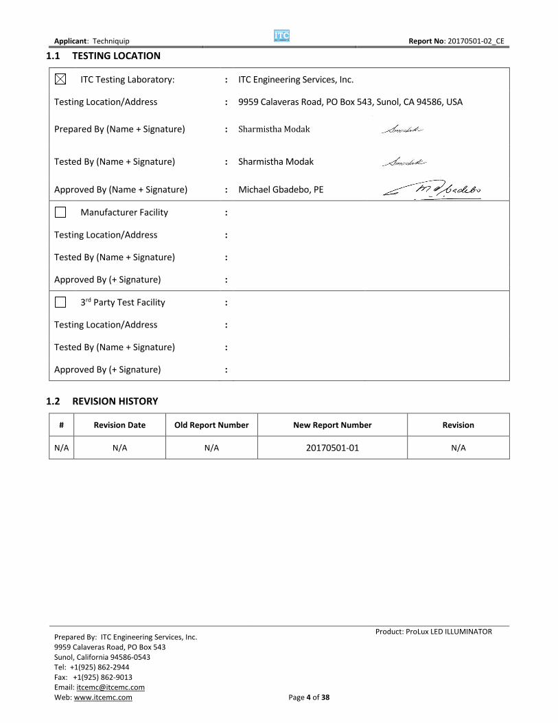
1.1 TESTING LOCATION
ITC Testing Laboratory: : ITC Engineering Services, Inc.
Testing Location/Address : 9959 Calaveras Road, PO Box 543, Sunol, CA 94586, USA
Prepared By (Name + Signature) : Sharmistha Modak
Tested By (Name + Signature) : Sharmistha Modak
Approved By (Name + Signature) : Michael Gbadebo, PE
Manufacturer Facility :
Testing Location/Address :
Tested By (Name + Signature) :
Approved By (+ Signature) :
3rd Party Test Facility :
Testing Location/Address :
Tested By (Name + Signature) :
Approved By (+ Signature) :
1.2 REVISION HISTORY
# Revision Date Old Report Number New Report Number Revision
N/A N/A N/A 20170501-01 N/A

Applicant: Techniquip
Report No: 20170501-02_CE
Prepared By: ITC Engineering Services, Inc. 9959 Calaveras Road, PO Box 543 Sunol, California 94586-0543 Tel: +1(925) 862-2944 Fax: +1(925) 862-9013 Email: [email protected] Web: www.itcemc.com
Page 5 of 38
Product: ProLux LED ILLUMINATOR
1.3 SUMMARY OF TESTS
ITC Engineering Services, Inc. as an independent testing laboratory, declares that the equipment specified above was tested to the requirements of:
1. EMISSIONS REGULATIONS: including
1. CISPR11:2015 + AMD1: 2016 Class A
2. IEC 61000-3-2: 2014
3. IEC 61000-3-3:2013 + AMD1 :2017
2. IMMUNITY REGULATIONS:IEC 61000-6-2: 2016 including
1. IEC 61000-4-2:2008
2. IEC 61000-4-3: 2010
3. IEC 61000-4-4: 2012
4. IEC 61000-4-5:2014
5. IEC 61000-4-6:2013 Cor 1:2015
6. IEC 61000-4-8:2009
7. IEC 61000-4-11:2004 + AMD1: 2017
1.4 DECLARATION/DISCLAIMER
It is the manufacturer's responsibility to assure that additional production units of these models are manufactured with identical electrical and mechanical characteristics. This report is the confidential property of the applicant. As a mutual protection to our applicants, the public, and ourselves, extracts from the test report shall not be reproduced except in full without ITC Engineering Service’s written approval. The applicant/manufacturer shall not use this report to claim product endorsement by any US Government agency.
1.5 CONDITION OF EUT
Equipment Under Test (EUT) was tested as it was received.
1.6 GENERAL DESCRIPTION OF EUT
ProLux is a source of continuous high intensity illumination intended to deliver illumination only through non-electrical light cables made with optical fibers or optical cavities for use providing illumination for optical fibers in a variety of industries.
1.7 EUT PORTS AND CONNECTORS
Ports and connectors:
1. AC Power Outlet 2. Light Cable port

Applicant: Techniquip
Report No: 20170501-02_CE
Prepared By: ITC Engineering Services, Inc. 9959 Calaveras Road, PO Box 543 Sunol, California 94586-0543 Tel: +1(925) 862-2944 Fax: +1(925) 862-9013 Email: [email protected] Web: www.itcemc.com
Page 6 of 38
Product: ProLux LED ILLUMINATOR
1.8 LIST OF PERIPHERALS USED DURING TEST
Description Manufacturer Model Name Serial Number
N\A N\A N\A
1.9 GENERAL TEST REMARKS
The EUT was operated under the following conditions during the testing:
Standby Test Program (H - Pattern)
Test Program (Color Bar) Test Program (Applicant Specific)
TV/VCR Signal Input Signal Generator Input
Continuous Audio Tone (1kHz) Cycled Audio Tone (1kHz)
Printer/Parallel Function Modem/Serial Function
Serpentine Program with I/O Serpentine Program without I/O
Practice Operation Normal Operating Mode
Essential Operation (Functional Safety) Continuous Unmonitored Operation
Continuous Monitored Operation Non-Continuous Operation
Does the EUT Meet the Requirements in Accordance with Technical Regulations?
Meets Regulation Requirements Does Not Meet Regulation Requirements
Does the EUT Fulfill the Customer’s Requirements?
Fulfills the customer’s requirements Does Not fulfill the customer’s requirements

Applicant: Techniquip
Report No: 20170501-02_CE
Prepared By: ITC Engineering Services, Inc. 9959 Calaveras Road, PO Box 543 Sunol, California 94586-0543 Tel: +1(925) 862-2944 Fax: +1(925) 862-9013 Email: [email protected] Web: www.itcemc.com
Page 7 of 38
Product: ProLux LED ILLUMINATOR
2 EMISSIONS TESTS
2.1 RADIATED EMISSIONS PER CISPR11:2015 + AMD1: 2016 CLASS A
The EUT was placed on a wooden turntable 80 cm above a ground reference plane in the Semi-Anechoic Chamber. The EUT was then powered on and placed in an operational mode. Radiated emissions were monitored from 30MHz to 1GHz using antennas placed ten meters from the EUT. The antennas were oriented in both horizonal and vertical polarizations and were elevated from one to four meters while the unit was rotated and monitored. The results were recorded.
2.1.1 ADMINISTRATIVE AND ENVIRONMENTAL DETAILS
Site Used: Semi-Anechoic Chamber
Test Date: 5/23/17
Test Engineer: Sharmistha Modak
Temperature: 25°C
Humidity: 43 %
2.1.2 TEST EQUIPMENT
Equipment Description Manufacturer Model Name Serial Number Calibration Due Date Biconical Antenna EMCO 3104 3459 1/09/2018
L. P. Antenna EMCO 3146 1596/1001 5/23/2018
Horn Antenna EMCO 3115 11966E 2/03/2018
EMC Analyzer Agilent E7405A US40240257 7/16/17 *CNR – Calibration Not Required
2.1.3 TEST RESULTS
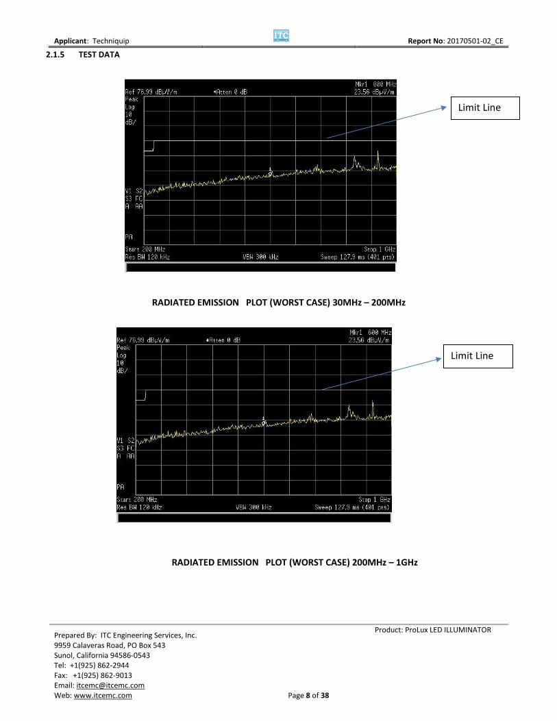
The EUT meets the requirements of the test for Radiated Emissions per CISPR11:2015 + AMD1: 2016 Class A.
2.1.4 MEASUREMENT UNCERTAINTY
UNCERTAINTY OF RADIATED EMISSIONSMEASUREMENT – 30MHZ THROUGH 1 GHZ
Uncertainty Contribution Value Data Source Prob. Dist. Divisor
1 Antenna (Bi-conical / Log Periodic) .82 Cal. Lab Normal k = 2
2 Cable loss /Attenuator 0.5 Historical record Normal k = 1
3 Receiver/SA Specification 2.3 Mfg. Spec. Rectangular 1.73
4 Mismatch 0.5 Historical record “U” 1.41
5 Site Corrections: Site Imperfections:
4.0 Site Atten. Data
Triangular
2.45
6 Separation Distance: at 3m 0.2 Site Atten. Data Rectangular 1.73
7 Combined Standard Uncertainty uc(y)
2.62 Normal
8 Expanded Uncertainty U 4.47 Normal k = 2
Combined Standard Uncertainty Calculation(y) = [(.82/2)2 + (0.5/1)2 + (2.3/1.73)2 + (0.5/1.41)2 + (4.0/2.45)2 + (0.2/1.73)2]1/2= (0.168 + 0.25 + 1.77 + 0.126 + 2.65 + 0.013) 1/2 = 2.622 (uc (y) ) = Ulab = ± 5.24
Applicant: Techniquip
Report No: 20170501-02_CE
Prepared By: ITC Engineering Services, Inc. 9959 Calaveras Road, PO Box 543 Sunol, California 94586-0543 Tel: +1(925) 862-2944 Fax: +1(925) 862-9013 Email: [email protected] Web: www.itcemc.com
Page 8 of 38
Product: ProLux LED ILLUMINATOR
2.1.5 TEST DATA
RADIATED EMISSION PLOT (WORST CASE) 30MHz – 200MHz
RADIATED EMISSION PLOT (WORST CASE) 200MHz – 1GHz
Limit Line
Limit Line

Applicant: Techniquip
Report No: 20170501-02_CE
Prepared By: ITC Engineering Services, Inc. 9959 Calaveras Road, PO Box 543 Sunol, California 94586-0543 Tel: +1(925) 862-2944 Fax: +1(925) 862-9013 Email: [email protected] Web: www.itcemc.com
Page 9 of 38
Product: ProLux LED ILLUMINATOR
2.1.6 TEST SETUP PHOTO
Radiated Emission Set-up for 30 – 200 MHz
Radiated Emission Set-up for 0.02 – 1 GHz

Applicant: Techniquip
Report No: 20170501-02_CE
Prepared By: ITC Engineering Services, Inc. 9959 Calaveras Road, PO Box 543 Sunol, California 94586-0543 Tel: +1(925) 862-2944 Fax: +1(925) 862-9013 Email: [email protected] Web: www.itcemc.com
Page 10 of 38
Product: ProLux LED ILLUMINATOR
2.2 CONDUCTED EMISSIONS PER CISPR11:2015 + AMD1: 2016 CLASS A
The EUT was placed in a shielded room 80 cm above the horizontal ground reference plane and 40 cm away from the vertical ground reference plane. Power input to the EUT was supplied through a LISN (Line Impedence Stabilization Network) and the excess power cord was looped into figure “8” above the LISN. The EUT was powered on and placed in an operational mode. The line conducted tests were performed on hot and neutral lines.
2.2.1 ADMINISTRATIVE AND ENVIRONMENTAL DETAILS
Site Used: EMC Lab 2A
Test Date: 5/23/2017
Test Engineer: Sharmistha Modak
Temperature: 25°C
Humidity: 43 %
Test Voltage 2: 230 V~, 50 Hz
2.2.2 TEST EQUIPMENT
Equipment Description Manufacturer Model Name Serial Number Calibration Due Date EMC Analyzer Agilent E7405A US40240257 1/09/2018
Power Source California Instruments 1251R LO5211 VBU*
LISN (25 Amp) EMCO 3825/2 8901-1447 7/21/2017
2.2.3 TEST RESULTS
The EUT meets the requirements of the test for Conducted Emissions per CISPR11:2015 + AMD1: 2016 Class A..

Applicant: Techniquip
Report No: 20170501-02_CE
Prepared By: ITC Engineering Services, Inc. 9959 Calaveras Road, PO Box 543 Sunol, California 94586-0543 Tel: +1(925) 862-2944 Fax: +1(925) 862-9013 Email: [email protected] Web: www.itcemc.com
Page 11 of 38
Product: ProLux LED ILLUMINATOR
2.2.4 TEST DATA
HOT LINE CONDUCTED EMISSIONS ( 230V 50HZ )
NEUTRAL LINE CONDUCTED EMISSIONS (230V 50HZ )
Limit Line
Limit Line

Applicant: Techniquip
Report No: 20170501-02_CE
Prepared By: ITC Engineering Services, Inc. 9959 Calaveras Road, PO Box 543 Sunol, California 94586-0543 Tel: +1(925) 862-2944 Fax: +1(925) 862-9013 Email: [email protected] Web: www.itcemc.com
Page 12 of 38
Product: ProLux LED ILLUMINATOR
2.2.5 MEASUREMENT UNCERTAINTY
UNCERTAINTY OF CONDUCTED EMISSIONS
MEASUREMENT – 150KHZ THROUGH 30MHZ
Uncertainty Contribution Value Data Source Prob. Dist. Divisor
1 Cable and Attenuator Calibration 0.5 Historical Data Normal k = 1
2 Receiver/SA specification 2.0 Mfg. Spec. Rectangular 1.73
3
Receiver Corrections: Sine Wave Voltage Pulse Amplitude Response Pulse Repetition Rate Response
±0.55 ± 1.5 ± 0.75
Mfg. Spec.
Normal Rectangular Rectangular
k = 2 1.73 1.73
4 LISN coupling specification 2.0 Cal. Lab. Normal k = 2
5 Mismatch 0.26 Estimation “U” 1.41
6 Combined Standard Uncertainty uc(y)
1.91
Normal
7 Expanded Uncertainty U 3.82 Normal k = 2
Combined Standard Uncertainty Calculation: uc(y) = [(0.5/1)2 + (2.0/1.73)2 + (0.55/2)2 + (1.5/1.73)2 + (0.75/1.73)2 + (2.0/2)2 + (0.26/1.41)2]1/2
= (0.25 + 1.34 +.076 + .75 +.19 + 1 + .034) 1/2 = 1.91 2 (uc (y) ) = Ulab = ± 3.82
2.2.6 CONDUCTED TEST SETUP
AC Line Conducted Emission Test Set-up

Applicant: Techniquip
Report No: 20170501-02_CE
Prepared By: ITC Engineering Services, Inc. 9959 Calaveras Road, PO Box 543 Sunol, California 94586-0543 Tel: +1(925) 862-2944 Fax: +1(925) 862-9013 Email: [email protected] Web: www.itcemc.com
Page 13 of 38
Product: ProLux LED ILLUMINATOR
2.3 POWER LINE HARMONICS PER IEC 61000-3-2: 2014
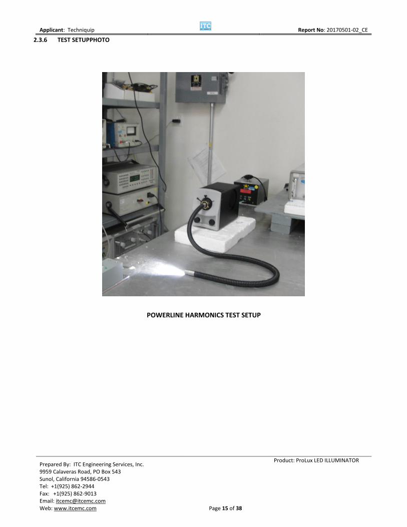
The EUT was placed in a shielded room supplied with filtered power. The line power input to the EUT was supplied through a reference impedance network. The unit was powered on and placed into an operational mode. A power analyzer and associated software were used to collect the data.
2.3.1 ADMINISTRATIVE AND ENVIRONMENTAL DETAILS
Site Used: EMC Lab 2A
Test Date: 5/26/2017
Test Engineer: Sharmistha Modak
Temperature: 20°C
Humidity: 45%
2.3.2 TEST EQUIPMENT
Equipment Description Manufacturer Model Serial Number Calibration Due Date Universal Power Analyzer Voltech PM3000A AL32/2834 7/13/2018
Reference Impedance Network Voltech IEC Standard 555
1B07/9032 7/13/2018
Computer e-machines T1095 QCG1BK1000432 N/A
Keyboard HP KB-9970 9L21203044B N/A
Mouse Dell 851841-1000 LZF35011718 N/A
Monitor View Sonic VA702b PSX053011858 N/A
2.3.3 SOFTWARE USED
Description Manufacturer Model Name Version Number
Test Software Voltech IEC1000-3/IEC555 3.13.08
2.3.4 TEST RESULTS
The EUT meets the requirements of the Power Line Harmonics test per IEC 61000-3-2: 2014.

Applicant: Techniquip
Report No: 20170501-02_CE
Prepared By: ITC Engineering Services, Inc. 9959 Calaveras Road, PO Box 543 Sunol, California 94586-0543 Tel: +1(925) 862-2944 Fax: +1(925) 862-9013 Email: [email protected] Web: www.itcemc.com
Page 14 of 38
Product: ProLux LED ILLUMINATOR
2.3.5 TEST DATA
POWER LINE HARMONICS TEST DATA (230V, 50HZ)
Applicant: Techniquip
Report No: 20170501-02_CE
Prepared By: ITC Engineering Services, Inc. 9959 Calaveras Road, PO Box 543 Sunol, California 94586-0543 Tel: +1(925) 862-2944 Fax: +1(925) 862-9013 Email: [email protected] Web: www.itcemc.com
Page 15 of 38
Product: ProLux LED ILLUMINATOR
2.3.6 TEST SETUPPHOTO
POWERLINE HARMONICS TEST SETUP

Applicant: Techniquip
Report No: 20170501-02_CE
Prepared By: ITC Engineering Services, Inc. 9959 Calaveras Road, PO Box 543 Sunol, California 94586-0543 Tel: +1(925) 862-2944 Fax: +1(925) 862-9013 Email: [email protected] Web: www.itcemc.com
Page 16 of 38
Product: ProLux LED ILLUMINATOR
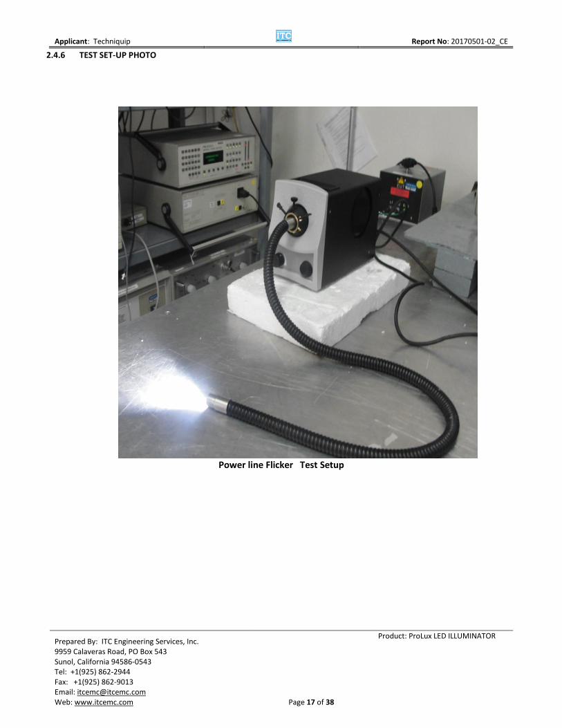
2.4 POWER LINE FLICKER PER IEC 61000-3-3:2013 + AMD1 :2017
The EUT was placed on the test surface in a shielded room supplied with filtered power. The input power of the EUT was passed through a Reference Impedance Network. The EUT was powered on and placed in an operational mode. A power analyzer and associated software was used to collect the data.
2.4.1 ADMINISTRATIVE AND ENVIRONMENTAL DETAILS
Site Used: EMC Lab 2A
Test Date: 5/26/2017
Test Engineer: Sharmistha Modak
Temperature: 20 C
Humidity: 45 %
2.4.2 TEST EQUIPMENT
Equipment Description Manufacturer Model Name Serial Number Calibration Due Date
Universal Power Analyzer Voltech PM3000A AL32/2834 7/13/2017
Reference Impedance Network Voltech IEC Standard 555
1B07/9032 7/13/2017
Computer e-machines T1095 QCG1BK1000432 N/A
Keyboard HP KB-9970 9L21203044B N/A
Mouse Dell 851841-1000 LZF35011718 N/A
Monitor View Sonic VA702b PSX053011858 N/A
2.4.3 SOFTWARE USED
Description Manufacturer Model Name Version Number
Test Software Voltech IEC1000-3/IEC555 3.13.08
2.4.4 TEST RESULTS
The EUT meets the requirements for the Power Line Flicker test per IEC 61000-3-3:2013 + AMD1 :2017.
2.4.5 TEST DATA
Flicker Emissions Data Result at 230Vac 50 Hz
Applicant: Techniquip
Report No: 20170501-02_CE
Prepared By: ITC Engineering Services, Inc. 9959 Calaveras Road, PO Box 543 Sunol, California 94586-0543 Tel: +1(925) 862-2944 Fax: +1(925) 862-9013 Email: [email protected] Web: www.itcemc.com
Page 17 of 38
Product: ProLux LED ILLUMINATOR
2.4.6 TEST SET-UP PHOTO
Power line Flicker Test Setup
Applicant: Techniquip
Report No: 20170501-02_CE
Prepared By: ITC Engineering Services, Inc. 9959 Calaveras Road, PO Box 543 Sunol, California 94586-0543 Tel: +1(925) 862-2944 Fax: +1(925) 862-9013 Email: [email protected] Web: www.itcemc.com
Page 18 of 38
Product: ProLux LED ILLUMINATOR
3 IMMUNITY TESTS PER IEC 61000-6-2:2016
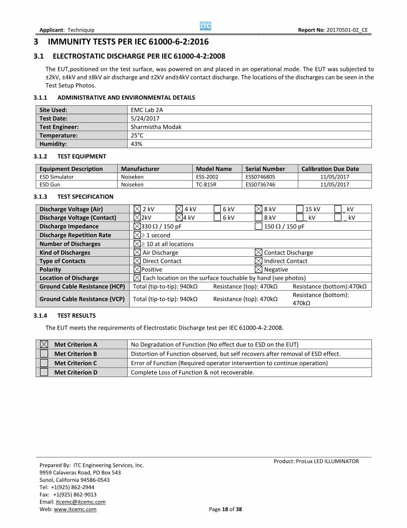
3.1 ELECTROSTATIC DISCHARGE PER IEC 61000-4-2:2008
The EUT,positioned on the test surface, was powered on and placed in an operational mode. The EUT was subjected to ±2kV, ±4kV and ±8kV air discharge and ±2kV and±4kV contact discharge. The locations of the discharges can be seen in the Test Setup Photos.
3.1.1 ADMINISTRATIVE AND ENVIRONMENTAL DETAILS
Site Used: EMC Lab 2A
Test Date: 5/24/2017
Test Engineer: Sharmistha Modak
Temperature: 25°C
Humidity: 43%
3.1.2 TEST EQUIPMENT
Equipment Description Manufacturer Model Name Serial Number Calibration Due Date ESD Simulator Noiseken ESS-2002 ESS0746805 11/05/2017
ESD Gun Noiseken TC-815R ESS0736746 11/05/2017
3.1.3 TEST SPECIFICATION
Discharge Voltage (Air) 2 kV 4 kV 6 kV 8 kV 15 kV _ kV
Discharge Voltage (Contact) 2kV 4 kV 6 kV 8 kV _ kV _ kV
Discharge Impedance 330 / 150 pF 150 / 150 pF
Discharge Repetition Rate 1 second
Number of Discharges 10 at all locations
Kind of Discharges Air Discharge Contact Discharge
Type of Contacts Direct Contact Indirect Contact
Polarity Positive Negative
Location of Discharge Each location on the surface touchable by hand (see photos)
Ground Cable Resistance (HCP) Total (tip-to-tip): 940kΩ Resistance (top): 470kΩ Resistance (bottom):470kΩ
Ground Cable Resistance (VCP) Total (tip-to-tip): 940kΩ Resistance (top): 470kΩ Resistance (bottom): 470kΩ
3.1.4 TEST RESULTS
The EUT meets the requirements of Electrostatic Discharge test per IEC 61000-4-2:2008.
Met Criterion A No Degradation of Function (No effect due to ESD on the EUT)
Met Criterion B Distortion of Function observed, but self recovers after removal of ESD effect.
Met Criterion C Error of Function (Required operator intervention to continue operation)
Met Criterion D Complete Loss of Function & not recoverable.

Applicant: Techniquip
Report No: 20170501-02_CE
Prepared By: ITC Engineering Services, Inc. 9959 Calaveras Road, PO Box 543 Sunol, California 94586-0543 Tel: +1(925) 862-2944 Fax: +1(925) 862-9013 Email: [email protected] Web: www.itcemc.com
Page 19 of 38
Product: ProLux LED ILLUMINATOR
3.1.5 TEST DATA
3.1.6 ESD TEST DISCHARGE POINTS
EUT Front ESD
ESD TEST DATA SHEET Electrostatic Discharge 61000-4-2
Indirect Positive Polarity Negative Polarity
(To coupling planes) (kV) (kV)
2 4 6 8 2 4 6 8
Horizontal Coupling Plane 10 10 10 10
Vertical Coupling Plane 10 10 10 10
Positive Polarity Negative Polarity
(kV) (kV)
Direct Air Level 1 Level 2 Level 3 Level 4 Level 1 Level 2 Level 3 Level
4
(To EUT) 2 4 8 15 2 4 8 15
Light Cable 0 0 0 0 0 0
Fan Vent 10 10 10 10 10 10
Front Knobs 0 0 0 0 0 0
Positive Polarity Negative Polarity
(kV) (kV)
Direct Contact Level 1 Level 2 Level 3 Level 4 Level 1 Level 2 Level 3 Level
4
(To EUT) 2 4 6 8 2 4 6 8
All Screws 10 10 10 10
AC Port 10 10 10 10
Chassis 10 10 10 10
Test Result: PASS

Applicant: Techniquip
Report No: 20170501-02_CE
Prepared By: ITC Engineering Services, Inc. 9959 Calaveras Road, PO Box 543 Sunol, California 94586-0543 Tel: +1(925) 862-2944 Fax: +1(925) 862-9013 Email: [email protected] Web: www.itcemc.com
Page 20 of 38
Product: ProLux LED ILLUMINATOR
EUT Back ESD

Applicant: Techniquip
Report No: 20170501-02_CE
Prepared By: ITC Engineering Services, Inc. 9959 Calaveras Road, PO Box 543 Sunol, California 94586-0543 Tel: +1(925) 862-2944 Fax: +1(925) 862-9013 Email: [email protected] Web: www.itcemc.com
Page 21 of 38
Product: ProLux LED ILLUMINATOR
EUT Right Side ESD
EUT LeftSide ESD
ESD DISCHARGE POINTS ( CONTACT POINT ; AIR POINT )

Applicant: Techniquip
Report No: 20170501-02_CE
Prepared By: ITC Engineering Services, Inc. 9959 Calaveras Road, PO Box 543 Sunol, California 94586-0543 Tel: +1(925) 862-2944 Fax: +1(925) 862-9013 Email: [email protected] Web: www.itcemc.com
Page 22 of 38
Product: ProLux LED ILLUMINATOR
3.1.7 TEST SETUP PHOTO
ESD Test Set-up

Applicant: Techniquip
Report No: 20170501-02_CE
Prepared By: ITC Engineering Services, Inc. 9959 Calaveras Road, PO Box 543 Sunol, California 94586-0543 Tel: +1(925) 862-2944 Fax: +1(925) 862-9013 Email: [email protected] Web: www.itcemc.com
Page 23 of 38
Product: ProLux LED ILLUMINATOR
3.2 RADIATED RF ELECTROMAGNETIC FIELDS PER IEC 61000-4-3: 2010
The EUT was placed on a test surface 80 cm above the ground plane in the Semi-Anechoic Chamber. The EUT was powered on and placed in an operational mode. It was then monitored while being subjected to RF radiation on all sides from 80 MHz to 2.7GHz at 3 V/m in horizontal and vertical polarization.
3.2.1 ADMINISTRATIVE AND ENVIRONMENTAL DETAILS
Site Used: Semi-Anechoic Chamber
Test Date: 5/30/2017
Test Engineer: Sharmistha Modak
Temperature: 25°C
Humidity: 43%
3.2.2 TEST EQUIPMENT
Equipment Description Manufacturer Model Name Serial Number Calibration Due Date
Power Amplifier OphirRF 5163F 1030 CNR**
Power Amplifier Amplifier Research 250A250A 29034 CNR**
Power Amplifier IFI SMX200 L387-0407 CNR**
L. P. Antenna (80-1000 MHz) Amplifier Research AT 1100 10537 10/14/2017
DRGH Antenna (1000-2500 MHz) AH Systems SAS-571 587 10/14/2017
Signal Generator Giga-tronics 2550B 919003 11/25/2017
Isotropic Field Probe ETS LINDGREN HI-4455 60849 10/15/2017
*N/A – Not Applicable; **CNR – Calibration Not Required
3.2.3 TEST SPECIFICATION
Frequency Range 27 MHz – 500 MHz 26MHz – 1000MHz
9 kHz – 27 MHz 80MHz – 2.7GHz
Field Strength 1 V/m 3 V/m 10 V/m _V/m
Distance Antenna – EUT 1 m 3 m
Modulation
AM 80 % 1 kHz
FM __ % _ kHz
Sine Wave Square Pulsed Unmodulated
Step 1% Custom < 0.015 decades/sec
Polarization of Antenna Horizontal Vertical
3.2.4 TEST RESULTS
The EUT meets the requirements for the Radiated Immunity test per IEC 61000-4-3: 2006 +A1: 2007 +A2: 2010.
Met Criterion A No Degradation of Function (No effect due to RF on the EUT)
Met Criterion B Distortion of Function observed, but self recovers.
Met Criterion C Error of Function (Required operator intervention to continue operation)
Met Criterion D Complete Loss of Function & not recoverable.

Applicant: Techniquip
Report No: 20170501-02_CE
Prepared By: ITC Engineering Services, Inc. 9959 Calaveras Road, PO Box 543 Sunol, California 94586-0543 Tel: +1(925) 862-2944 Fax: +1(925) 862-9013 Email: [email protected] Web: www.itcemc.com
Page 24 of 38
Product: ProLux LED ILLUMINATOR
3.2.5 MEASUREMENT UNCERTAINTY
3.2.6 TEST SETUP PHOTO
radiated immunity test setup (0.08GHz – 1 Ghz ) radiated immunity test setup ( 1GHz – 2.7 Ghz )
UNCERTAINTY OF RADIATED IMMUNITY MEASUREMENT – 80MHz TO 1GHz
Uncertainty Contribution Value Data Source Probability Dist. Divisor
1 Power Amplifier Harmonics 0.75 Mfg. Spec Rectangular 1.73
3 Forward Power Measurement Drift 0.5 Historical Rec. Rectangular 1.73
4 F/S Monitor 0.7 Cal-Lab Normal 2.00
5 F/S Accept. Window 0.5 Historical Rec. Rectangular 1.73
6 Effect of Field Disturbance 0.0 Rectangular 1.73
7 Measurement System Repeatability ± 0.5 Historical Rec. Normal 1.00
8 Combined Standard Uncertainty uc(y) ± 0.85
9 Expanded Uncertainty U ± 1.71 k =2.00
Combined Standard Uncertainty Calculation:uc(y)= [(0.75/1.73)2 + (0.5/1.73)2 + (0.7/2)2 + (0.5/1.73)2 + (0.0/1.73)2 + (0.5/1)2]½ =[0.19 + 0.084 + 0.12 + 0.084 + 0 + 0.25]½ = 0.852 (uc (y) ) = Ulab = ± 1.71

Applicant: Techniquip
Report No: 20170501-02_CE
Prepared By: ITC Engineering Services, Inc. 9959 Calaveras Road, PO Box 543 Sunol, California 94586-0543 Tel: +1(925) 862-2944 Fax: +1(925) 862-9013 Email: [email protected] Web: www.itcemc.com
Page 25 of 38
Product: ProLux LED ILLUMINATOR
3.3 ELECTRICAL FAST TRANSIENT PER IEC 61000-4-4: 2012
The EUT was placed on the test surfacein a shielded room. The power input of the unit was routed through the Burst-Tester Mainframe. The EUT was powered on and placed in an operational mode. The unit was monitored during the test.
3.3.1 ADMINISTRATIVE AND ENVIRONMENTAL DETAILS
Site Used: EMC Lab 2A
Test Date: 5/30/2017
Test Engineer: Sharmistha Modak
Temperature: 25°C
Humidity: 43%
Test Voltage 2: 230V, 50Hz
3.3.2 TEST EQUIPMENT
Equipment Description Manufacturer Model Name Serial Number Calibration Due Date
Burst-Tester Haefely PEFT.1 081 979-03 VBU*
Coupling Clamp Haefely 093 506.1 083 839 -11 VBU* *Verified Before Use
3.3.3 TEST SPECIFICATION
Pulse Amplitude - AC Power Port 0.5 KV 1.0 KV 2.0 KV 4.0 KV
Pulse Amplitude - DC Power Port 0.5 KV 1.0 KV 2.0 KV 4.0 KV
Pulse Amplitude - Signal/Data 0.5 KV 1.0 KV 2.0 KV ___KV
N. C. Port Pulse Amplitude - Proc. 0.5 KV 1.0 KV 2.0 KV ___KV
Meas. & C. Port Burst Freq. 2.5 kHz 5.0 kHz ___ kHz
Burst Duration 5/50 ns ___ ns
Time of Coupling 60 seconds ___ seconds
Coupling Method Coupling Clamp Coupling. /Decoupling. Network
Polarity Positive Negative
3.3.4 COUPLED LINES
Name of Lines AC Power Cord
Type of Lines Shielded Unshielded
Status of Lines Active Passive
3.3.5 TEST RESULTS
The EUT meets the requirements for Electrical Fast Transients per IEC 61000-4-4: 2012.
Met Criterion A No Degradation of Function (No effect due to EFT on the EUT)
Met Criterion B Distortion of Function observed, but self recovers.*
Met Criterion Error of Function (Required operator intervention to continue operation)
Met Criterion D Complete Loss of Function & not recoverable. *Power line applied burst causes optical USB mouse LED to flicker, cursor freezes, disappears and reappears. Normal function returns without user intervention when upset is removed.

Applicant: Techniquip
Report No: 20170501-02_CE
Prepared By: ITC Engineering Services, Inc. 9959 Calaveras Road, PO Box 543 Sunol, California 94586-0543 Tel: +1(925) 862-2944 Fax: +1(925) 862-9013 Email: [email protected] Web: www.itcemc.com
Page 26 of 38
Product: ProLux LED ILLUMINATOR
3.3.6 TEST SETUP PHOTOS
EFT Test Set-up at Power Line
Applicant: Techniquip
Report No: 20170501-02_CE
Prepared By: ITC Engineering Services, Inc. 9959 Calaveras Road, PO Box 543 Sunol, California 94586-0543 Tel: +1(925) 862-2944 Fax: +1(925) 862-9013 Email: [email protected] Web: www.itcemc.com
Page 27 of 38
Product: ProLux LED ILLUMINATOR
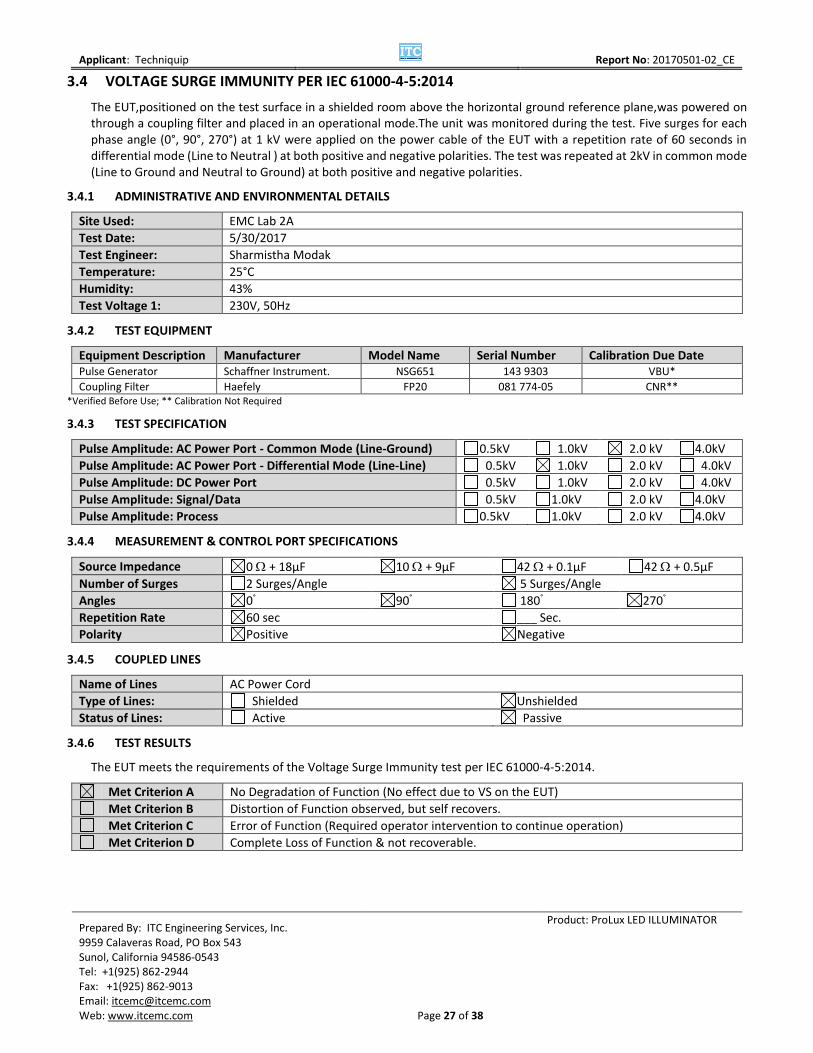
3.4 VOLTAGE SURGE IMMUNITY PER IEC 61000-4-5:2014
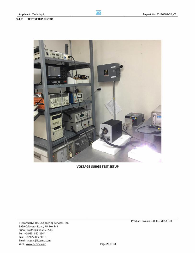
The EUT,positioned on the test surface in a shielded room above the horizontal ground reference plane,was powered on through a coupling filter and placed in an operational mode.The unit was monitored during the test. Five surges for each phase angle (0°, 90°, 270°) at 1 kV were applied on the power cable of the EUT with a repetition rate of 60 seconds in differential mode (Line to Neutral ) at both positive and negative polarities. The test was repeated at 2kV in common mode (Line to Ground and Neutral to Ground) at both positive and negative polarities.
3.4.1 ADMINISTRATIVE AND ENVIRONMENTAL DETAILS
Site Used: EMC Lab 2A
Test Date: 5/30/2017
Test Engineer: Sharmistha Modak
Temperature: 25°C
Humidity: 43%
Test Voltage 1: 230V, 50Hz
3.4.2 TEST EQUIPMENT
Equipment Description Manufacturer Model Name Serial Number Calibration Due Date Pulse Generator Schaffner Instrument. NSG651 143 9303 VBU*
Coupling Filter Haefely FP20 081 774-05 CNR** *Verified Before Use; ** Calibration Not Required
3.4.3 TEST SPECIFICATION
Pulse Amplitude: AC Power Port - Common Mode (Line-Ground) 0.5kV 1.0kV 2.0 kV 4.0kV
Pulse Amplitude: AC Power Port - Differential Mode (Line-Line) 0.5kV 1.0kV 2.0 kV 4.0kV
Pulse Amplitude: DC Power Port 0.5kV 1.0kV 2.0 kV 4.0kV
Pulse Amplitude: Signal/Data 0.5kV 1.0kV 2.0 kV 4.0kV
Pulse Amplitude: Process 0.5kV 1.0kV 2.0 kV 4.0kV
3.4.4 MEASUREMENT & CONTROL PORT SPECIFICATIONS
Source Impedance 0 + 18µF 10 + 9µF 42 + 0.1µF 42 + 0.5µF
Number of Surges 2 Surges/Angle 5 Surges/Angle
Angles 0° 90° 180° 270°
Repetition Rate 60 sec ___ Sec.
Polarity Positive Negative
3.4.5 COUPLED LINES
Name of Lines AC Power Cord
Type of Lines: Shielded Unshielded
Status of Lines: Active Passive
3.4.6 TEST RESULTS
The EUT meets the requirements of the Voltage Surge Immunity test per IEC 61000-4-5:2014.
Met Criterion A No Degradation of Function (No effect due to VS on the EUT)
Met Criterion B Distortion of Function observed, but self recovers.
Met Criterion C Error of Function (Required operator intervention to continue operation)
Met Criterion D Complete Loss of Function & not recoverable.
Applicant: Techniquip
Report No: 20170501-02_CE
Prepared By: ITC Engineering Services, Inc. 9959 Calaveras Road, PO Box 543 Sunol, California 94586-0543 Tel: +1(925) 862-2944 Fax: +1(925) 862-9013 Email: [email protected] Web: www.itcemc.com
Page 28 of 38
Product: ProLux LED ILLUMINATOR
3.4.7 TEST SETUP PHOTO
VOLTAGE SURGE TEST SETUP

Applicant: Techniquip
Report No: 20170501-02_CE
Prepared By: ITC Engineering Services, Inc. 9959 Calaveras Road, PO Box 543 Sunol, California 94586-0543 Tel: +1(925) 862-2944 Fax: +1(925) 862-9013 Email: [email protected] Web: www.itcemc.com
Page 29 of 38
Product: ProLux LED ILLUMINATOR
+1kV L-N -1kV L-N
+2kV PE-N -2kV PE-N
+2kV PE-L -2kV PE-L

Applicant: Techniquip
Report No: 20170501-02_CE
Prepared By: ITC Engineering Services, Inc. 9959 Calaveras Road, PO Box 543 Sunol, California 94586-0543 Tel: +1(925) 862-2944 Fax: +1(925) 862-9013 Email: [email protected] Web: www.itcemc.com
Page 30 of 38
Product: ProLux LED ILLUMINATOR
3.5 CONDUCTEDIMMUNITY PER IEC 61000-4-6:2013 COR.1 2015
The EUT,positioned on the test surface in the shielded room,was powered on and placed in an operational mode. The line power for the EUT was passed through a Coupling/ Decoupling Network (CDN) and injected with 3Vrms at carrier frequencies from 150 KHz to 80 MHz, with 80% amplitude modulation @ 1 KHz, while the EUT was monitored for errors.
3.5.1 ADMINISTRATIVE AND ENVIRONMENTAL DETAILS
Site Used: EMC Lab 2A
Test Date: 5/31/2017
Test Engineer: Sharmistha Modak
Temperature: 25°C
Humidity: 43%
Test Voltage 230V~, 50 Hz
3.5.2 TEST EQUIPMENT
Equipment Description Manufacturer Model Name Serial Number Calibration Due Date Signal Generator Agilent 8648C 3847A05285 3/31/2018
RF Power Amplifier ENI 310L 115‐220 CNR*
Oscilloscope Tektronix TDS7104 B020599 1/09/2018
Passive Impedance Adapter Fisher Custom
Communications FCC-801-150-50-
CDN 2014 CNR**
Passive Impedance Adapter Fisher Custom
Communications, Inc. FCC-801-150-50-
CDN 2013 CNR**
Power line Coupling/ Decoupling Network
Fisher Custom Communication, Inc.
FCC-801-M3-25A 2002 CNR*
* Calibration Not Required; **Verified Before Use
3.5.3 TEST SPECIFICATION
Frequency Range 150 kHz - 80 MHz 26 MHz – 80 MHz
Field Strength 1 Vrms 3 Vrms 10 Vrms _ Vrms
Modulation AM 80 % 1kHz
FM __ kHz Rate
Step < 0.015 decades / sec 1% Custom
Sine Wave Unmodulated
3.5.4 TEST RESULTS
The EUT meets the requirements for Conducted Immunity per IEC 61000-4-6:2013 COR1 :2015
Met Criterion A No Degradation of Function (No effect due to CI on the EUT)
Met Criterion B Distortion of Function observed, but self recovers.
Met Criterion C Error of Function (Required operator intervention to continue operation)
Met Criterion D Complete Loss of Function & not recoverable.

Applicant: Techniquip
Report No: 20170501-02_CE
Prepared By: ITC Engineering Services, Inc. 9959 Calaveras Road, PO Box 543 Sunol, California 94586-0543 Tel: +1(925) 862-2944 Fax: +1(925) 862-9013 Email: [email protected] Web: www.itcemc.com
Page 31 of 38
Product: ProLux LED ILLUMINATOR
3.5.5 MEASUREMENT UNCERTAINTY
UNCERTAINTY OF CONDUCTED IMMUNTIY MEASUREMENTS – 150KHz TO 80MHz
Uncertainty Contribution 3m Value Data Source Probability Dist. Divisor 1 RMS Voltmeter 0.3 Mfg. Spec. Rectangular 1.73 2 Volt. Level Accept. Window 0.5 Mfg. Spec. Rectangular 1.73 3 Power Amp. Harmonics 0.75 Mfg. Spec. Rectangular 1.73 4 Signal Generator Drift 0.5 Mfg. Spec. Rectangular 1.73
5
Mismatch rms Voltmeter CDN
0.5 Historical Record “U” 1.41
6
Mismatch Amplifier CDN + 6dB Attenuator
0.5 Historical Record “U” 1.41
7 Meas. System Repeatability 0.5 Historical Record Normal 1.00 8 Combined Standard Uncertainty uc(y) ± 1.73 9 Expanded Uncertainty U ± 3.46 k =2
Combined Standard Uncertainty Calculation(y)= [(0.3/1.73)2 + (0.5/1.73)2 + (0.75/1.73)2 + (0.5/1.73)2 + (0.5/1.41)2 + (0.5/1.41)2 + (0.5/1)2]½ = [0.18 + 1.34 + 1.34 + 0.125]½ = 1.732 (uc (y) ) = Ulab = ± 3.46
3.5.6 TEST SETUP PHOTO
CONDUCTED IMMUNITY TEST SETUP
Applicant: Techniquip
Report No: 20170501-02_CE
Prepared By: ITC Engineering Services, Inc. 9959 Calaveras Road, PO Box 543 Sunol, California 94586-0543 Tel: +1(925) 862-2944 Fax: +1(925) 862-9013 Email: [email protected] Web: www.itcemc.com
Page 32 of 38
Product: ProLux LED ILLUMINATOR
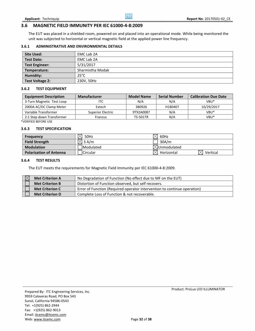
3.6 MAGNETIC FIELD IMMUNITY PER IEC 61000-4-8:2009
The EUT was placed in a shielded room, powered on and placed into an operational mode. While being monitored the unit was subjected to horizontal or vertical magnetic field at the applied power line frequency.
3.6.1 ADMINISTRATIVE AND ENVIRONMENTAL DETAILS
Site Used: EMC Lab 2A
Test Date: EMC Lab 2A
Test Engineer: 5/31/2017
Temperature: Sharmistha Modak
Humidity: 25°C
Test Voltage 2: 230V, 50Hz
3.6.2 TEST EQUIPMENT
Equipment Description Manufacturer Model Name Serial Number Calibration Due Date 3-Turn Magnetic Test Loop ITC N/A N/A VBU*
2000A AC/DC Clamp Meter Extech 380926 H180407 10/29/2017
Variable Transformer Superior Electric 9T92A0087 N/A VBU* 2:1 Step down Transformer Franzus TS-501TR N/A VBU*
*VERIFIED BEFORE USE
3.6.3 TEST SPECIFICATION
Frequency 50Hz 60Hz
Field Strength 3 A/m 30A/m
Modulation Modulated Unmodulated
Polarization of Antenna Circular Horizontal Vertical
3.6.4 TEST RESULTS
The EUT meets the requirements for Magnetic Field Immunity per IEC 61000-4-8:2009.
Met Criterion A No Degradation of Function (No effect due to MF on the EUT)
Met Criterion B Distortion of Function observed, but self recovers.
Met Criterion C Error of Function (Required operator intervention to continue operation)
Met Criterion D Complete Loss of Function & not recoverable.
Applicant: Techniquip
Report No: 20170501-02_CE
Prepared By: ITC Engineering Services, Inc. 9959 Calaveras Road, PO Box 543 Sunol, California 94586-0543 Tel: +1(925) 862-2944 Fax: +1(925) 862-9013 Email: [email protected] Web: www.itcemc.com
Page 33 of 38
Product: ProLux LED ILLUMINATOR
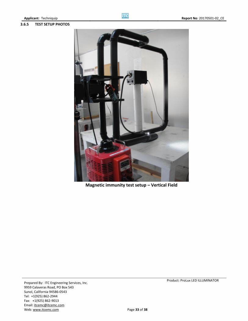
3.6.5 TEST SETUP PHOTOS
Magnetic immunity test setup – Vertical Field

Applicant: Techniquip
Report No: 20170501-02_CE
Prepared By: ITC Engineering Services, Inc. 9959 Calaveras Road, PO Box 543 Sunol, California 94586-0543 Tel: +1(925) 862-2944 Fax: +1(925) 862-9013 Email: [email protected] Web: www.itcemc.com
Page 34 of 38
Product: ProLux LED ILLUMINATOR
Magnetic immunity test setup – Horizontal Field

Applicant: Techniquip
Report No: 20170501-02_CE
Prepared By: ITC Engineering Services, Inc. 9959 Calaveras Road, PO Box 543 Sunol, California 94586-0543 Tel: +1(925) 862-2944 Fax: +1(925) 862-9013 Email: [email protected] Web: www.itcemc.com
Page 35 of 38
Product: ProLux LED ILLUMINATOR
3.7 POWER LINE DIPS AND BROWN OUTS PER IEC 61000-4-11:2004 AMD1:2017
The EUT,positioned on the test surface in a shielded room above the horizontal reference plane,was powered on and placed in an operational mode.The Line Voltage Simulator was placed in series with the power input of the EUT. The voltage interuptions and brownouts were conducted on the power line of the EUT while it was observed for errors.
3.7.1 ADMINISTRATIVE AND ENVIRONMENTAL DETAILS
Site Used: EMC Lab 2A
Test Date: 5/31/2017
Test Engineer: Sharmistha Modak
Temperature: 25°C
Humidity: 43%
Test Voltage 1: 230 V , 50 Hz
3.7.2 TEST EQUIPMENT
Equipment Description Manufacturer Model Name Serial Number Calibration Due Date Voltage Dip and Up Simulator Noiseken VDS-2002 VDS0720190 VBU*
*VBU – Verified Before Use
3.7.3 TEST SPECIFICATION
Test Level %UT Voltage Dips and Short Interruptions %UT Duration (In period)
0 >95 (Dip) .5/1 cycle
70 30 (Dip) 25/30 cycles
0 >95 (Interruption) 250/300 cycles
3.7.4 TEST RESULTS
The EUTmeets the Power Line Dips and Brown-out requirements per IEC 61000-4-11:2004. AMD1:2017
Unit lost power during 0% Test level with 250/300 cycle duration and recovered power after few seconds.
Met Criterion A No Degradation of Function (No effect due to Dips & Brown Outs on the EUT)
Met Criterion B Distortion of Function observed, but self recovers.
Met Criterion C Error of Function (Required operator intervention to continue operation)
Met Criterion D Complete Loss of Function & not recoverable.
Applicant: Techniquip
Report No: 20170501-02_CE
Prepared By: ITC Engineering Services, Inc. 9959 Calaveras Road, PO Box 543 Sunol, California 94586-0543 Tel: +1(925) 862-2944 Fax: +1(925) 862-9013 Email: [email protected] Web: www.itcemc.com
Page 36 of 38
Product: ProLux LED ILLUMINATOR
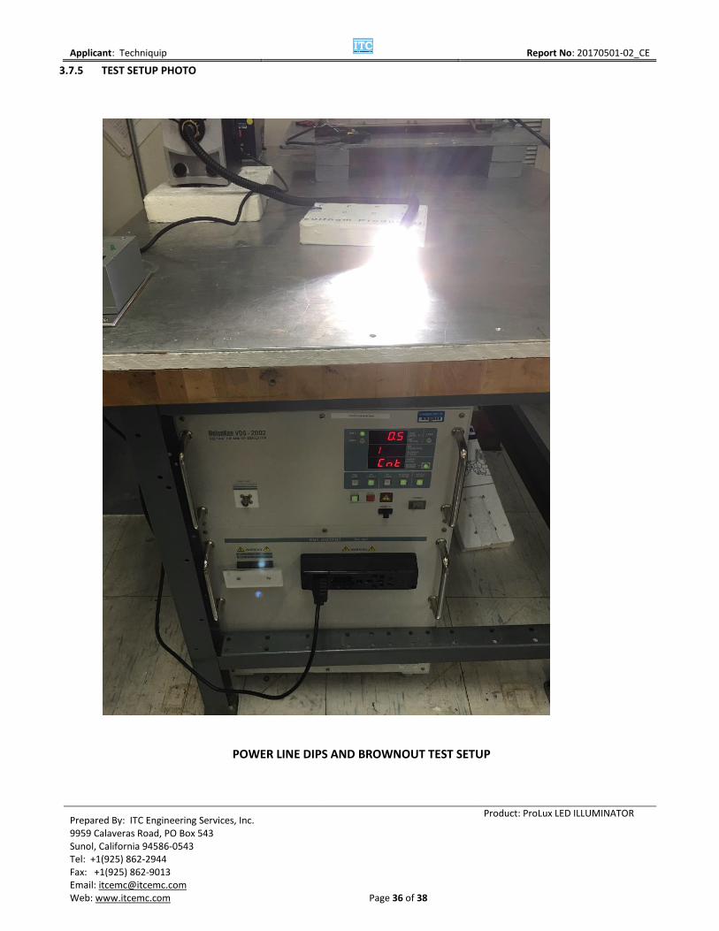
3.7.5 TEST SETUP PHOTO
POWER LINE DIPS AND BROWNOUT TEST SETUP
Applicant: Techniquip
Report No: 20170501-02_CE
Prepared By: ITC Engineering Services, Inc. 9959 Calaveras Road, PO Box 543 Sunol, California 94586-0543 Tel: +1(925) 862-2944 Fax: +1(925) 862-9013 Email: [email protected] Web: www.itcemc.com
Page 37 of 38
Product: ProLux LED ILLUMINATOR
4 APPENDIX
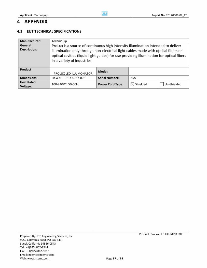
4.1 EUT TECHNICAL SPECIFICATIONS
Manufacturer: Techniquip
General Description:
ProLux is a source of continuous high intensity illumination intended to deliver illumination only through non-electrical light cables made with optical fibers or optical cavities (liquid light guides) for use providing illumination for optical fibers in a variety of industries.
Product PROLUX LED ILLUMONATOR
Model:
Dimensions: HXWXL 6” X 4.5”X 8.5” Serial Number: N\A
Host Rated Voltage:
100-240V~, 50-60Hz Power Cord Type: Shielded Un-Shielded

Applicant: Techniquip
Report No: 20170501-02_CE
Prepared By: ITC Engineering Services, Inc. 9959 Calaveras Road, PO Box 543 Sunol, California 94586-0543 Tel: +1(925) 862-2944 Fax: +1(925) 862-9013 Email: [email protected] Web: www.itcemc.com
Page 38 of 38
Product: ProLux LED ILLUMINATOR
4.2 MODIFICATION LETTER
No modifications were done to the EUT during testing. To Whom It May Concern: The EUT, ProLux LED Illuminator described in this report, was tested to the requirements of the standards below:
• EMISSIONS REGULATIONS:
O CISPR11:2015 + AMD1: 2016 Class A
O IEC 61000-3-2: 2014
O IEC 61000-3-3:2013 + AMD1 :2017
• IMMUNITY REGULATIONS:IEC 61000-6-2: 2016 including
O IEC 61000-4-2:2008
O IEC 61000-4-3: 2010
O IEC 61000-4-4: 2012
O IEC 61000-4-5:2014
O IEC 61000-4-6:2013 Cor 1:2015
o IEC 61000-4-8:2009
o IEC 61000-4-11:2004 + AMD1: 2017
For further information, please contact the manufacturer at:
Mr. David Wensley 530 Boulder Ct. # 103 Place Pleasanton, CA 94588 Phone: 925-251-9036 Email: [email protected]