item #0429713 ceiling fan light kit
TRANSCRIPT

1
Lowes.com/harborbreeze
Questions, problems, missing parts? Before returning to your retailer, call our customer service department at 1-800-643-0067, 8 a.m. - 6 p.m., EST, Monday - Thursday, 8 a.m. - 5 p.m., EST, Friday.
ATTACH YOUR RECEIPT HERE
Serial Number ____________ Purchase Date ____________
AB13137
Harbor Breeze® is a registered trademark of LF, LLC. All Rights Reserved.
ITEM #0429713
CEILING FAN LIGHT KITMODEL #40313
Español p. 9

2
Lowes.com/harborbreeze
PART DESCRIPTION QUANTITYA Light Kit Fitter 1B Glass Shade 1C Finial Plate 5D Finial 5E Pull Chain Extension 1
AA BB CC
Hex Nut(preassembled to Light Kit Fitter (A))
Qty. 2
Lock Washer(preassembled to Light Kit Fitter (A))
Qty. 1
Rubber Washer(preassembled to Light Kit Fitter (A))
Qty. 1
PACKAGE CONTENTS
HARDWARE CONTENTS
H
arbor Breeze
A
E
B
C
D

3
Lowes.com/harborbreeze
SAFETY INFORMATION
Please read and understand this entire manual before attempting to assemble, operate or install the product. Failure to do so could lead to electrical shock, fire or other injuries that could be hazardous or even fatal.• Before you begin installing the light kit, disconnect the power by removing fuses or turning off the
circuit breakers. • Make sure all electrical connections comply with local codes, ordinances, the National Electrical
Code, and ANSI/NFPA 70-199. Hire a qualified electrician or consult a do-it-yourself wiring handbook if you are unfamiliar with installing electrical wiring.
• The net weight of the light kit is less than 4.4 lbs.
DANGER: • DO NOT connect this fixture to an electrical system that does not provide a means for equipment
grounding. Never use a fixture in a two-wire system that is not grounded. Installing a fixture into an electrical system not having a proper grounding means could cause metal parts of the fixture to carry electrical currents if any of the fixture wires, wire connections or splices were to become broken, cut or loose during the mounting or normal operation of the fixture. Under this condition, anyone coming in contact with the fixture would be subject to electrical shock, which could cause serious injury or death.
• DO NOT connect the bare or green insulation fixture ground wire to the black (hot) current-carrying wire or the white neutral house wire. Connection of the bare or green fixture ground wire to the black or white house wires may cause metal parts of the fixture to carry electrical currents. Under this condition anyone coming in contact with the fixture will receive electrical shock, which could cause serious injury or death.
• DO NOT damage or cut the wire insulation (covering) during installation of the fixture. DO NOT permit wires to contact any surface having a sharp edge. To do so may damage or cut the wire insulation, which could cause serious injury or death from electrical shock.
WARNING: • All electrical connections must be in agreement with local codes and ordinances, the National
Electric Code (NEC) and ANSI/NFPA 70-1999. Contact your municipal building department to learn about your local codes, permits and/or inspections. Risk of fire - most dwellings built before 1985 have supply wire rated for 140°F. Consult a qualified electrician before installation.
• To avoid personal injury, the use of gloves may be necessary while handling fixture parts with sharp edges.
• DO NOT suspend any fixture by the house wires. A fixture must always be mounted directly to a ceiling fan that is mounted directly to an outlet box. Wire connectors will not support the weight of a fixture. Suspending a fixture by the house wires and wire connectors will result in the fixture falling, with the possibility of personal injury and the danger of electrical shock or fire.
• To reduce the risk of fire, electrical shock, or personal injury, each wire connector used with this light kit should accept only one 18-gauge wire from the light kit and one 18-gauge wire from the ceiling fan. If there are three or more wires to connect or any of the wires is larger than 18 gauges, consult an electrician for the proper size wire connectors to use.

4
Lowes.com/harborbreeze
SAFETY INFORMATION
CAUTION: • TURN OFF ELECTRICITY at the main fuse box (or circuit breaker box) before beginning
installation by removing the fuse (or switching the circuit breaker off). If you are not sure the lighting system has a grounding means, DO NOT attempt to install this fixture. Contact a qualified, licensed electrician for information regarding the proper grounding methods as required by the local electrical code in your area.
• All fixtures must be mounted to a ceiling fan that is mounted to an outlet box that is supported by the building structure.
• DO NOT use bulbs having a wattage greater than the maximum value stated on the fixture. The use of bulbs with higher wattage than specified will increase temperatures and risk of fire.
• If a dimmer control switch is used with this fixture, obtain professional advice to determine the correct type to use as well as the electrical rating required.
PREPARATION
Before beginning the assembly of this product, ensure that all parts are present. Compare all parts with the package contents list and hardware contents list. If any part is missing or damaged, do not attempt to assemble the product.Estimated Assembly Time: 30 minutesTools Required for Assembly (not included): Flathead screwdriver, Phillips screwdriver, pliers, wire cutters, safety glasses, step ladder, wire connectors (included with fan), and electrical tapeHelpful Tools (not included): Wire strippers, A/C tester light, wiring handbook, soft cloth
ASSEMBLY INSTRUCTIONS
1. Turn off the circuit breakers and the wall switch to the fan supply line leads.
DANGER: Failure to disconnect the power supply prior to installation may result in serious injury or death.
1
5
Lowes.com/harborbreeze
ASSEMBLY INSTRUCTIONS
Hardware Used
Hex Nut x 1
x 1
AA
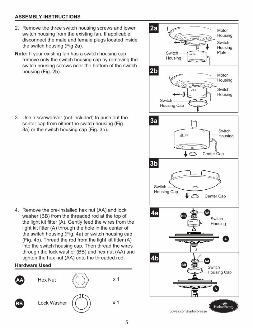
2. Remove the three switch housing screws and lower switch housing from the existing fan. If applicable, disconnect the male and female plugs located inside the switch housing (Fig 2a).
Note: If your existing fan has a switch housing cap, remove only the switch housing cap by removing the switch housing screws near the bottom of the switch housing (Fig. 2b).
3. Use a screwdriver (not included) to push out the center cap from either the switch housing (Fig. 3a) or the switch housing cap (Fig. 3b).
4. Remove the pre-installed hex nut (AA) and lock washer (BB) from the threaded rod at the top of the light kit fitter (A). Gently feed the wires from the light kit fitter (A) through the hole in the center of the switch housing (Fig. 4a) or switch housing cap (Fig. 4b). Thread the rod from the light kit fitter (A) into the switch housing cap. Then thread the wires through the lock washer (BB) and hex nut (AA) and tighten the hex nut (AA) onto the threaded rod.
2a
2b
3a
3b
4b
4a
BBAA
A
BB
BB
BB
A
AA
A
AA
Lock Washer
Switch Housing
Switch Housing
Center Cap
Center Cap
Switch Housing
Switch Housing
Motor Housing
Motor Housing
Switch Housing Cap
Switch Housing Cap
Switch Housing Cap
Switch Housing Plate

6
Lowes.com/harborbreeze
ASSEMBLY INSTRUCTIONS
White
WhiteBlack
Blue
5a
5b
A
White WhiteBlack Blue
6
5. Remove the wire connectors from the white and blue wires labeled FOR LIGHT in the switch housing. Connect the white wire from the light kit fitter (A) to the white wire from the fan. Connect the black wire from the light kit fitter (A) to the blue wire from the fan. (Fig. 5a/Fig. 5b) If applicable, reconnect the male plug from the motor housing to the female plug from the switch housing. Ensure the plugs connect securely (Fig. 5a).WARNING: To reduce the risk of fire, electrical shock or personal injury, each wire connector used with this light kit should accept only one 18-gauge wire from the light kit and one 18-gauge wire from the ceiling fan. If there are three or more wires to connect or any of the wires is larger than 18 gauges, consult an electrician for the proper size wire connectors to use.
6. Reconnect the wire connectors and twist in a clockwise direction. Wrap electrical tape (not included) around each individual wire connector down to the wire.
7. Align three holes in the switch housing cap with three holes in the switch housing plate. Reattach the switch housing with the three screws that were removed in Step 2. Tighten all screws securely (Fig.7a).
Note: To reconnect the switch housing cap, align the holes in the switch housing cap with the holes at the bottom of the switch housing and use the three previously removed screws to secure the switch housing cap. (Fig. 7b).
Note: When attaching switch housing or switch housing cap, turn assembly as necessary to ensure fan pull chain falls between glass shades and functions without interference.
7a
7b
Switch Housing
Switch Housing
Motor Housing
Male Plug
Female Plug
Switch Housing Cap
Switch Housing
Motor Housing
Motor Housing
Switch Housing Plate
A
A
A
A
7
Lowes.com/harborbreeze
ASSEMBLY INSTRUCTIONS
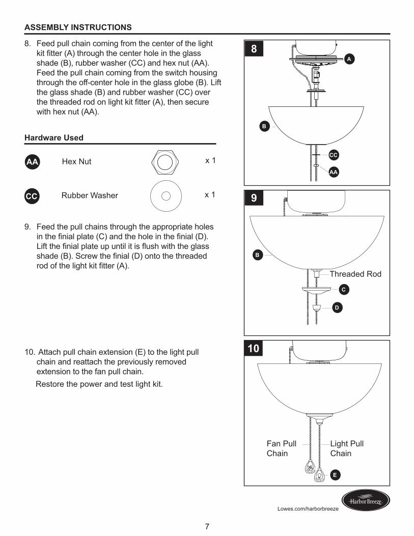
8. Feed pull chain coming from the center of the light kit fitter (A) through the center hole in the glass shade (B), rubber washer (CC) and hex nut (AA). Feed the pull chain coming from the switch housing through the off-center hole in the glass globe (B). Lift the glass shade (B) and rubber washer (CC) over the threaded rod on light kit fitter (A), then secure with hex nut (AA).
9. Feed the pull chains through the appropriate holes in the finial plate (C) and the hole in the finial (D). Lift the finial plate up until it is flush with the glass shade (B). Screw the finial (D) onto the threaded rod of the light kit fitter (A).
10. Attach pull chain extension (E) to the light pull chain and reattach the previously removed extension to the fan pull chain.
Restore the power and test light kit.
H
arbor Breeze
H
arbor Breeze
8
9
10
E
B
A
B
AA
C
D
CC
Threaded Rod
Light Pull Chain
Fan Pull Chain
Hardware Used
Hex Nut x 1
x 1
AA
CC Rubber Washer
8
Lowes.com/harborbreeze
TROUBLESHOOTING
ONE-YEAR LIMITED WARRANTY
REPLACEMENT PARTS
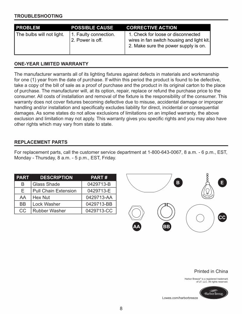
The manufacturer warrants all of its lighting fixtures against defects in materials and workmanship for one (1) year from the date of purchase. If within this period the product is found to be defective, take a copy of the bill of sale as a proof of purchase and the product in its original carton to the place of purchase. The manufacturer will, at its option, repair, replace or refund the purchase price to the consumer. All costs of installation and removal of the fixture is the responsibility of the consumer. This warranty does not cover fixtures becoming defective due to misuse, accidental damage or improper handling and/or installation and specifically excludes liability for direct, incidental or consequential damages. As some states do not allow exclusions of limitations on an implied warranty, the above exclusion and limitation may not apply. This warranty gives you specific rights and you may also have other rights which may vary from state to state.
PROBLEM POSSIBLE CAUSE CORRECTIVE ACTION The bulbs will not light. 1. Faulty connection.
2. Power is off.1. Check for loose or disconnected wires in fan switch housing and light kit. 2. Make sure the power supply is on.
For replacement parts, call the customer service department at 1-800-643-0067, 8 a.m. - 6 p.m., EST, Monday - Thursday, 8 a.m. - 5 p.m., EST, Friday.
PART DESCRIPTION PART #B Glass Shade 0429713-BE Pull Chain Extension 0429713-E
AA Hex Nut 0429713-AABB Lock Washer 0429713-BBCC Rubber Washer 0429713-CC
H
arbor Breeze
B E
CC
BBAA
Printed in ChinaHarbor Breeze® is a registered trademark
of LF, LLC. All rights reserved.

9Lowes.com/harborbreeze
¿Preguntas, problemas, piezas faltantes? Antes de volver a la tienda, llame a nuestro Departamento de Servicio al Cliente al 1-800-643-0067 de lunes a jueves de 8 a.m. a 6 p.m. y los viernes de 8 a.m. a 5 p.m., hora estándar del Este.
ADJUNTE SU RECIBO AQUÍ
Número de serie ____________ Fecha de compra ____________
Harbor Breeze® es una marca registrada de LF, LLC. Todos los derechos reservados.
ARTÍCULO # 0429713
KIT DE ILUMINACIÓN PARA VENTILADOR DE TECHO
MODELO #40313

10Lowes.com/harborbreeze
PIEZA DESCRIPCIÓN CANTIDADA Soporte del kit de iluminación 1B Pantalla de vidrio 1C Placa del remate 5D Remate 5E Extensión para la cadena de tiro 1
AA BB CC
Tuerca hexagonal(preensamblada en el soporte del kit de
iluminación (A))Cant. 2
Arandela de seguridad(preensamblada en el soporte del kit de
iluminación (A))Cant. 1
Arandela de goma(preensamblada en el soporte del kit de
iluminación (A))Cant. 1
CONTENIDO DEL PAQUETE
ADITAMENTOS
H
arbor Breeze
A
E
B
C
D

11Lowes.com/harborbreeze
INFORMACIÓN DE SEGURIDAD
Lea y comprenda completamente este manual antes de intentar ensamblar, usar o instalar el producto. No hacerlo podría provocar descargas eléctricas, incendios u otras lesiones, las que pueden ser peligrosas o incluso fatales.• Antes de comenzar a instalar el kit de iluminación, desconecte la alimentación eléctrica; para esto
retire los fusibles o coloque el interruptor de circuito en la posición de apagado. • Asegúrese de que todas las conexiones eléctricas cumplan con los códigos y ordenanzas locales, el
Código Eléctrico Nacional y la norma ANSI/NFPA 70-199. Si no está familiarizado con la instalación delcableadoeléctrico,contrateaunelectricistacalificadooconsulteunmanualdecableadoparahacerlo usted mismo.
• El peso neto del kit de iluminación es menor que 2 kg.PELIGRO:
• NO conecte esta lámpara a un sistema eléctrico que no proporcione un medio de puesta a tierra para el equipo. Nunca utilice una lámpara en un sistema de dos conductores que no tenga puesta a tierra. Instalar una lámpara en un sistema eléctrico que no tenga una puesta a tierra adecuada podría provocar que las piezas de metal de la lámpara conduzcan corriente eléctrica si cualquiera de los cables, las conexiones del cableado o los empalmes de la lámpara se rompen, se cortan o se sueltan durante el montaje o funcionamiento normal. En esta situación, cualquier persona que entre en contacto con la lámpara podría recibir una descarga eléctrica, la que podría provocar lesiones graves o la muerte.
• NO conecte el conductor de puesta a tierra de aislamiento desnudo o verde de la lámpara al conductor negro (de corriente) que lleva la corriente o al conductor blanco neutro de la casa. Conectar el conductor de tierra desnudo o verde de la lámpara al conductor negro o blanco interior puede provocar que las piezas metálicas de la lámpara conduzcan corriente eléctrica. En esta situación, cualquier persona que entre en contacto con el ensamble recibirá una descarga eléctrica, la que podría provocar lesiones graves o la muerte.
• NO dañe ni corte el aislamiento del conductor (cubierta) durante la instalación de la lámpara. NO permitaquelosconductoresentrenencontactoconsuperficiesquetenganunbordeafilado,yaque esto podría dañar o cortar el aislamiento del conductor y provocar lesiones graves o la muerte debido a una descarga eléctrica.
ADVERTENCIA: • Todas las conexiones eléctricas deben cumplir con los códigos y ordenanzas locales, el Código
Nacional de Electricidad (NEC, por sus siglas en inglés) y la norma ANSI/NFPA 70-1999. Póngase en contacto con su Departamento de construcción municipal para consultar sobre sus códigos, permisos y/o inspecciones locales. Riesgo de incendio: La mayoría de las casas construidas antes de 1985 tienencablesconductoresclasificadospara60ºC.Consulteaunelectricistacalificadoantesdeinstalar.
• Para evitar lesiones personales, puede ser necesario usar guantes al manipular las piezas de la lámparaconbordesfilosos.
• NO cuelgue ninguna lámpara de los cables de la casa. Siempre se debe montar la lámpara directamente en un ventilador de techo que esté montado directamente en la caja de salida. Los conectores de cables no sostendrán el peso de una lámpara. Si cuelga una lámpara de los cables de la casa y los conectores de cables, ésta se caerá y podría provocar lesiones personales y peligro de descarga eléctrica o incendio.
• Para reducir el riesgo de incendios, descargas eléctricas o lesiones personales, cada conector de cable utilizado en este kit de iluminación debería soportar solo un conductor de calibre 18 del kit de iluminación y un conductor de calibre 18 del ventilador de techo. Si hay tres o más conductores para conectar o si cualquiera de los conductores tiene un calibre superior a 18, consulte a un electricista cuál es el tamaño adecuado de los conectores de cables que debe utilizar.

12Lowes.com/harborbreeze
INFORMACIÓN DE SEGURIDAD
PRECAUCIÓN:• DESCONECTE EL SUMINISTRO DE ELECTRICIDAD en la caja de fusibles principal (o desde
la caja del interruptor de circuito) antes de comenzar la instalación; para hacerlo, retire el fusible (o apague el interruptor de circuito). NO intente instalar esta lámpara si no está seguro de que su sistemadeiluminacióntieneunapuestaatierra.Póngaseencontactoconunelectricistacalificadoycertificadoparaobtenerinformaciónsobrelosmétodosadecuadosdepuestaatierraexigidospor el código local de electricidad de su área.
• Todas las lámparas se deben montar directamente en un ventilador de techo que esté montado en unacajadesalida,laqueasuvezestásostenidadelaestructuradeledificio.
• NO utilice bombillas de un vataje mayor que el valor máximo establecido en la lámpara. La utilizacióndebombillascuyovatajeseamayorqueelespecificadoincrementarálatemperaturayproducirá riesgo de incendio.
• Si se utiliza un regulador de control de intensidad con esta lámpara, solicite asesoría profesional paradeterminareltipoylaclasificacióneléctricacorrectaqueserequiere.
PREPARACIÓN
Antes de comenzar a ensamblar este producto, asegúrese de tener todas las piezas. Compare todas las piezas con la lista del contenido del paquete y la lista de aditamentos. No intente ensamblar el producto si falta alguna pieza o si estas están dañadas.Tiempo estimado de ensamblaje: 30 minutosHerramientas necesarias para el ensamblaje (no se incluyen): Destornillador de cabeza plana, destornillador Phillips, pinzas cortacables, gafas de seguridad, escalera de tijera, conectores de cable (incluidos con el ventilador) y cinta aislante.Herramientas útiles (no se incluyen): Pinzas pelacables, luz de prueba de C/A, manual de cableado, paño suave
INSTRUCCIONES DE ENSAMBLAJE
1. Gire los interruptores de circuito y el interruptor de pared hacia los conductores de la línea de suministro del ventilador.
PELIGRO: Si no interrumpe el suministro de electricidad antes de la instalación, pueden producirse lesiones graves o la muerte.
1
13Lowes.com/harborbreeze
INSTRUCCIONES DE ENSAMBLAJE
Aditamentos utilizados
Tuerca hexagonal x 1
x 1
AA
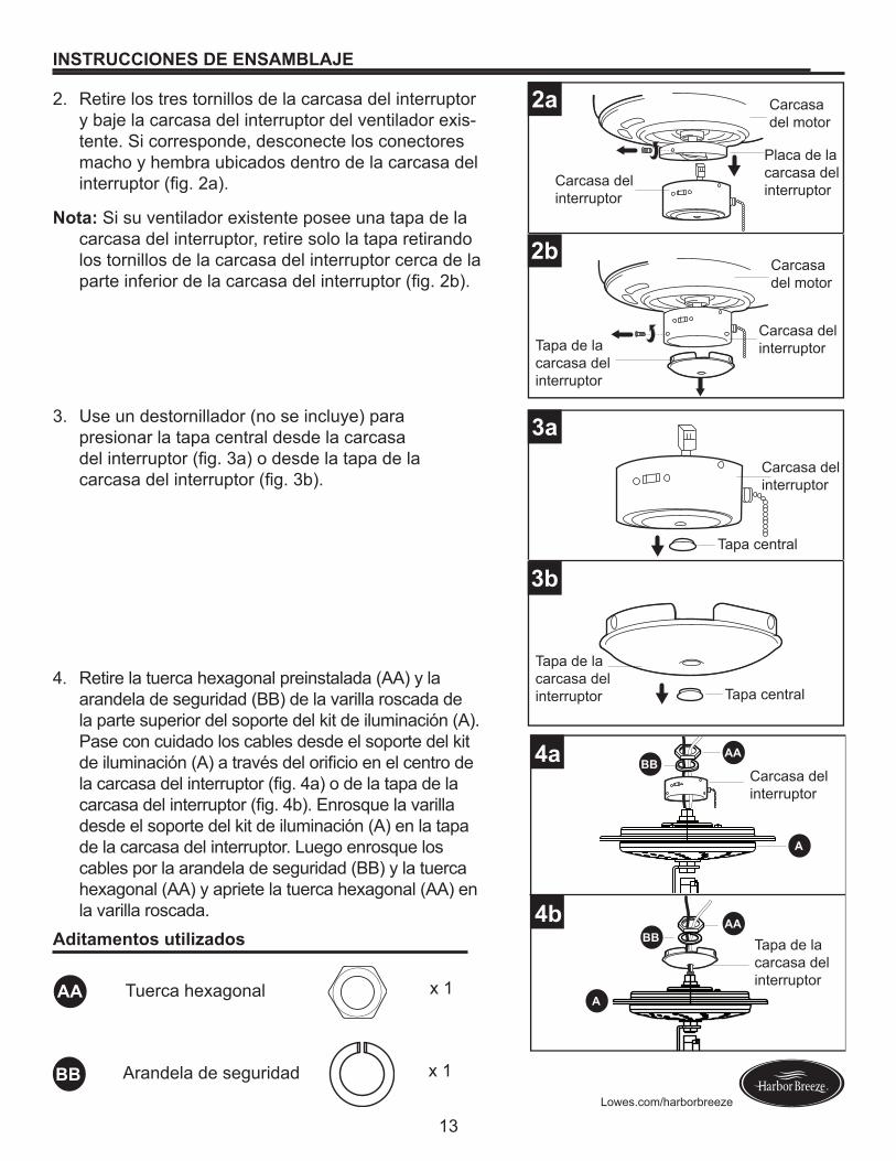
2. Retire los tres tornillos de la carcasa del interruptor y baje la carcasa del interruptor del ventilador exis-tente. Si corresponde, desconecte los conectores macho y hembra ubicados dentro de la carcasa del interruptor(fig.2a).
Nota: Si su ventilador existente posee una tapa de la carcasa del interruptor, retire solo la tapa retirando los tornillos de la carcasa del interruptor cerca de la parteinferiordelacarcasadelinterruptor(fig.2b).
3. Use un destornillador (no se incluye) para presionar la tapa central desde la carcasa delinterruptor(fig.3a)odesdelatapadelacarcasadelinterruptor(fig.3b).
4. Retire la tuerca hexagonal preinstalada (AA) y la arandela de seguridad (BB) de la varilla roscada de la parte superior del soporte del kit de iluminación (A). Pase con cuidado los cables desde el soporte del kit deiluminación(A)atravésdelorificioenelcentrodelacarcasadelinterruptor(fig.4a)odelatapadelacarcasadelinterruptor(fig.4b).Enrosquelavarilladesde el soporte del kit de iluminación (A) en la tapa de la carcasa del interruptor. Luego enrosque los cables por la arandela de seguridad (BB) y la tuerca hexagonal (AA) y apriete la tuerca hexagonal (AA) en la varilla roscada.
2a
2b
3a
3b
4b
4a
BBAA
A
BB
BB
BB
A
AA
A
AA
Arandela de seguridad
Tapa central
Tapa central
Carcasa del interruptor
Carcasa del interruptor
Carcasa del interruptor
Carcasa del interruptor
Carcasa del motor
Carcasa del motor
Tapa de la carcasa del interruptor
Tapa de la carcasa del interruptor
Tapa de la carcasa del interruptor
Placa de la carcasa del interruptor

14Lowes.com/harborbreeze
INSTRUCCIONES DE ENSAMBLAJE
Blanco
BlancoNegro
Azul
5a
5b
A
Blanco BlancoNegro Azul
6
5. Retire los conectores de cables de los conductores blanco y azul etiquetados como para la luz en la carcasa del interruptor. Conecte el conductor blanco del soporte del kit de iluminación (A) con el conductor blanco del ventilador. Conecte el conductor negro del soporte del kit de iluminación (A) con el conductor azul del ventilador. (Fig. 5a/Fig. 5b) Si corresponde, vuelva a conectar el conector macho de la carcasa del motor al conector hembra de la carcasa del interruptor. Asegúrese de que los conectores estén biencolocados(fig.5a).ADVERTENCIA: Para reducir el riesgo de incendios, descargas eléctricas o lesiones personales, cada conector de cable utilizado en este kit de iluminación debería soportar solo un conductor de calibre 18 del kit de iluminación y un conductor de calibre 18 del ventilador de techo. Si hay tres o más conductores para conectar o si cualquiera de los conductores tiene un calibre superior a 18, consulte a un electricista cuál es el tamaño adecuado de los conectores de cables que debe utilizar.
6. Vuelva a conectar los conectores de cables y gire en dirección de las manecillas del reloj. Cubra con cinta aislante (no se incluye) cada conector de cables individual hacia abajo del cable.
7. Alineelostresorificiosenlatapadelacarcasadelinterruptorconlostresorificiosenlaplacade la carcasa del interruptor. Vuelva a instalar la carcasa del interruptor con los tres tornillos que retiró en el paso 2. Apriete bien todos los tornillos (fig.7a).
Nota: Para volver a conectar la tapa de la carcasa delinterruptor,alineelosorificiosdelatapadelacarcasadelinterruptorconlosorificiosenlaparteinferior de esta y utilice los tres tornillos que retiró previamenteparafijarlatapadelacarcasadelinterruptor. (Fig. 7b).
Nota: Cuandofijelacarcasadelinterruptorolatapade la carcasa del interruptor, gire el ensamble si es necesario para asegurar de que la cadena de tiro del ventilador caiga por entre las pantallas de vidrio y funcione sin interferencia.
7a
7b
A
A
A
A
Carcasa del interruptor
Carcasa del interruptor
Carcasa del interruptor
Placa de la carcasa del interruptor
Carcasa del interruptor
Carcasa del motor
Carcasa del motor
Carcasa del motor
Conector macho
Conector hembra

15Lowes.com/harborbreeze
INSTRUCCIONES DE ENSAMBLAJE
8. Pase la cadena de tiro que viene del centro del soportedelkitdeiluminación(A)porelorificiocentral en la pantalla de vidrio (B), la arandela de goma (CC) y la tuerca hexagonal (AA). Pase la cadena de tiro que viene de la carcasa del interruptorporelorificiodescentradoenlapantallade vidrio (B). Suba la pantalla de vidrio (B) y la arandela de goma (CC) sobre la varilla roscada en el soporte del kit de iluminación (A) y asegure con la tuerca hexagonal (AA).
9. Paselascadenasdetiroatravésdelosorificioscorrectosenlaplacadelremate(C)yelorificioenel remate (D). Suba la placa del remate hasta que esté al ras de la pantalla de vidrio (B). Enrosque el remate (D) en la varilla roscada del soporte del kit de iluminación (A).
10. Fije la extensión de la cadena de tiro (E) a lacadenadetirodelaluzyvuelvaafijarlaextensión previamente retirada a la cadena de tiro del ventilador.
Restablezca la alimentación y pruebe el kit de iluminación.
H
arbor Breeze
H
arbor Breeze
8
9
10
E
B
A
B
AA
C
D
CC
Varilla roscada
Cadena de tiro de la luz
Cadena de tiro del ventilador
Aditamentos utilizados
Tuerca hexagonal x 1
x 1
AA
CC Arandela de goma

16Lowes.com/harborbreeze
SOLUCIÓN DE PROBLEMAS
UN AÑO DE GARANTÍA LIMITADA
PIEZAS DE REPUESTO
El fabricante garantiza que todas sus lámparas estarán libres de defectos en los materiales y la mano de obra por un (1) año a partir de la fecha de compra. Si dentro de este período el producto presenta defectos, lleve una copia del recibo de venta como comprobante de la compra y el producto en su caja original al lugar donde lo compró. El fabricante, a su elección, reparará, reemplazará o devolverá el monto de la compra al comprador. Todos los costos de instalación y de extracción de la lámpara son de responsabilidad del comprador. Esta garantía no cubre lámparas dañadas debido almaluso,dañoaccidental,manipulacióny/oinstalacióninadecuadayexcluyeespecíficamentetoda responsabilidad por daños directos, accidentales o resultantes. Debido a que algunos estados no permiten exclusiones o limitaciones en una garantía implícita, las exclusiones y limitaciones anteriorespuedennoaplicarseensucaso.Estagarantíaleotorgaderechosespecíficos,peropodríatener también otros derechos que varían según el estado.
PROBLEMA CAUSA POSIBLE ACCIÓN CORRECTIVA Las bombillas no se encienden.
1. La conexión es incorrecta. 2. No hay alimentación.
1. Verifiquesihaycablessueltosodesconectados en la carcasa del interruptor del ventilador y en el kit de iluminación. 2. Asegúrese de que haya suministro de electricidad.
Para obtener piezas de repuesto, llame al Departamento de Servicio al Cliente al 1-800-643-0067, de lunes a jueves de 8 a.m. a 6 p.m. y los viernes de 8 a.m. a 5 p.m., hora estándar del Este.
PIEZA DESCRIPCIÓN PIEZA #B Pantalla de vidrio 0429713-BE Extensión para la cadena de tiro 0429713-E
AA Tuerca hexagonal 0429713-AABB Arandela de seguridad 0429713-BBCC Arandela de goma 0429713-CC
H
arbor Breeze
B E
CC
BBAA Impreso en ChinaHarbor Breeze® es una marca registrada de LF, LLC.
Todos los derechos reservados.