iterative learning control for robotic-assisted … · iterative learning control for...
TRANSCRIPT
Iterative Learning Control for Robotic-assisted Upper Limb Stroke Rehabilitationin the Presence of Muscle Fatigue
Wenkang Xua, Bing Chub, Eric Rogersb,c
aSchool of Automation, Nanjing University of Science and Technology, Nanjing, China, 210094bElectronics and Computer Science, University of Southampton, Southampton, SO17 1BJ, UK
Abstract
The use of iterative learning control to regulate assistive functional electrical stimulation applied to the mus-
cles of patients undergoing robotic-assisted upper limb stroke rehabilitation has been followed through to
small scale clinical trials. These trials confirmed that an increase in patient ability to complete the specified
task also led to a reduction in the level of electrical stimulation required. This previous work assumed that
the effects of muscle fatigue could be neglected but if a patient suffers fatigue during a rehabilitation session
then their the session goals are not achieved or, more likely, the session must be abandoned due to the time
limits imposed by the ethical approval required to conduct such sessions. In this paper the results of the
first investigation into enhancing the control scheme to remove or lessen the effects of fatigue and hence
make better use of the time available for a session are given. The scheme considered adds a feedback loop
around the muscle model used, where the performance results given are based on a model for the dynamics
constructed using patient data collected in previous clinical trials.
Keywords: iterative learning control, stroke rehabilitation, multi-loop control.
1. Introduction
A common cause of a stroke is blockage of a blood vessel in the brain, where as a result regions down-
stream are starved of blood. Consequently, the connecting nerve cells die and this usually leads to partial
paralysis on one side of body, termed hemiplegia. Annually, 15 million people world-wide suffer a stroke
and up to a third of these are left with permanent impairment. Other demographic patterns and, in particular,
aging populations place even more strain on the resources for patient care and rehabilitation. Stroke is an
age-related disease National Audit Office (2006) and all of these factors contribute to an increasing burden
on long-term health and related resources. Hence there is a pressing need to improve the effectiveness of
treatments to achieve independence.
The brain cells that die as a result of a stroke cannot regrow but new connections can be made using
the brain’s spare capacity. In particular, the brain is continually and rapidly changing and as new skills are
learned, new connections are formed and redundant ones disappear. Relearning skills after a stroke is the
same process as a person learning an everyday task, such as reaching out to a cup, and requires sensory
Preprint submitted to Control Engineering Practice May 22, 2014
feedback during repeated practice of a task. This requires movement skills but the affects of the stroke
means that these are almost always very poor and hence feedback on performance is not obtained.
Stroke survivors commonly have a complex pattern of upper limb motor impairments with a loss in func-
tional abilities such as reaching. The coupling between reaching and independence is reflected in measures
of function independence, including the Barthel index van der Putten et al. (1999), where the ability to
reach is essential for approximately 50% of activities that make up daily living tasks. Currently, the level of
upper limb recovery following a stroke is poor and it has been reported Hendricks et al. (2002) that complete
recovery occurs in less than 15% of patients with initial paralysis. This and the age-related factor are among
the major reasons why there is a critical need to improve the effectiveness of treatments. If the stage were
reached where rehabilitation could be moved outside the hospital, which requires mobile technology, then
improved rehabilitation and reduced costs could be achieved.
The literature on conventional therapy plus motor learning theory, e.g., De Kroon et al. (2005), provides
evidence that functional recovery can be achieved through the facilitation of motor control and skill acquisi-
tion and restoration of muscle power through repetitive resistance exercises Krebs et al. (2003), in addition
to the variety of tasks and feedback. This knowledge has motivated the development of novel treatments,
such as robot-aided therapy, which could provide the basis longer-term for a translation of rehabilitation
clinics from labor-intensive work to technology-assisted operations and also an opportunity for repetitive
movement practice. Reviews of the robotic therapy literature, see Freeman et al. (2012a) and the cited ref-
erences, for the upper limb suggest that robot-assisted treatment improves motor control of the proximal
upper limb and may improve functional outcomes.
Rehabilitation robots are power driven or mechanically supported devices that assist a patient with lim-
ited physical capability to undertake repetitive exercises. The resulting sensory feedback is known to be
associated with cortical changes that facilitate the recovery of functional movement. Functional electrical
stimulation (FES) has been found to be applicable as another method of promoting cortical connectivity to
enable recovery, which is supported by a growing body of clinical evidence and theoretical support from
neurophysiology and motor learning research, again see Freeman et al. (2012a) for references to the litera-
ture and Lynch & Popovic (2008) for an overview of FES with a control systems perspective. Application of
FES to a muscle causes electrical impulses to travel along the nerves in the same way as electrical impulses
from the brain and if the stimulation is carefully regulated a useful movement can be made. In stroke reha-
bilitation FES is applied in combination with the patients voluntary effort with the aim of a specific recovery
of voluntary power Rushton (2003).
A wide range of algorithms have been applied to the control of FES for both the upper and lower limbs,
where again the literature is covered in Freeman et al. (2012a) and the cited references. In recent work
Iterative Learning Control (ILC) Bristow et al. (2006); Ahn et al. (2007) has been applied to regulate the
FES applied in robotic-assisted upper limb stroke rehabilitation. Earlier research on ILC regulated FES
2

applied to human limbs includes Dou et al. (1999).
Research on the application of ILC in this area started with a planar daily living motivated task, reaching
out over a table top, where the patient was asked to track a supplied reference trajectory whilst attached to
a robotic arm with assistive FES applied to the relevant muscle, i.e., the triceps. During each attempt, the
error between the desired trajectory and that produced by the patient was measured, the arm was then reset
to the starting location and in the time taken to complete this operation, plus a rest time, an ILC law was
used to compute the FES to be applied on the next attempt. This work proceeded to a clinical trial where the
required property that as the patient improves with repeated attempts voluntary effort increased and the level
of FES required decreased Freeman et al. (2009a,b); Hughes et al. (2009). This application area for ILC has
been extended to 3D tasks, such as reaching and extending the forearm, where there is a need to stimulate
more than one muscle and again clinical trial results are available Freeman et al. (2012a); Meadmore et al.
(2012).
In application, FES applied to muscles is at a higher frequency and is hence a contributory factor to
muscle fatigue. If the muscle suffers from fatigue then the force output drops and the treatment session
has to stop to allow recovery, which almost certainly means the session must end and the patient return at
another time, see Lynch & Popovic (2008) for a detailed control systems/modeling discussion of this area.
The previous research on ILC for upper-limb stroke rehabilitation did not explicitly account for muscle
fatigue in the model used for control law design but this aspect must be addressed if the use of model based
control laws in this and related problem areas is to proceed. This paper revisits the 3D task considered in the
previous work Freeman et al. (2012a); Meadmore et al. (2012), introduces a representation for the effects
of fatigue into the model for the response of the muscle to applied FES and adds a compensating feedback
control loop. Using this new representation, nonlinear model based ILC design is undertaken and the results
of a detailed simulation based evaluation of the new design given, where the dynamic model describing the
uncontrolled dynamics is constructed from data collected from patients participating in the previous clinical
study reported in Freeman et al. (2012a); Meadmore et al. (2012). Such an evaluation is an essential step
before seeking ethical approval for patient-based trials.
2. ILC for Stroke Rehabilitation
In this section, the robotic-assisted upper extremity stroke rehabilitation system used is introduced,
together with a detailed description of the modeling of fatigue.
2.1. The System Setup
Consider a gantry robot that performs the following sequence of operations i) collects an object from a
fixed location, ii) transfers it over a finite duration, iii) places it at a fixed location or on a moving conveyor
under synchronization, iv) returns to the starting location and v) repeat i)–iv) as many times as required
or until a stoppage for maintenance or other reasons is required. Each execution is termed a trial and
3
the duration the trial length. Once each trial is complete all information generated is available for use in
computing the control law for the next trial and ILC was developed for such cases.
Introduce the notation yk(t), 0 ≤ t ≤ T, k ≥ 0, where y is the vector or scalar valued variable under
consideration, the integer k denotes the trial number and T < ∞ is the finite trial length. Also let r(t) denote
the supplied reference signal, which is the same on all trials. Then the error on trial k is ek(t) = r(t)− yk(t)
and the basic ILC problem is to enforce convergence of the sequence {ek} in k where, if u is the input signal,
a commonly used form for the control law computes the input for trial k+1 as the sum of that used on trial
k plus a correction term whose computation is based on previous trial information and, in particular, the
previous trial error. Once a trial is complete all information generated over [0,T ] is available for use and, in
particular, information in t that is non-causal in the standard sense provided it is generated on a completed
trial.
One starting point for the background and literature on ILC is the survey papers Bristow et al. (2006);
Ahn et al. (2007). In ILC the control input is directly updated between trials and it is this feature that
makes it suitable for robotic assisted stroke rehabilitation. The previous section gave some of the supporting
literature on how a patient with hemiplegia can relearn everyday skills by repeated practice with assistive
FES. Moreover there is the requirement that if the patient is improving with each successive attempt, or
trial, the level of voluntary effort should increase and the assistive FES decrease. Hence the premise that
ILC could be used to regulate the FES applied.
The first research Freeman et al. (2009a,c) on the application of ILC in this area focused on a planar
task, such as reaching out over a table top to an object such as a cup. A lighted path to follow, the reference
signal in ILC terms, was beamed down from above and the patient’s affected arm was attached to a robot
with the task being to follow this prescribed path as closely as possible using a combination of voluntary
control and surface FES applied to muscles in their impaired shoulder and arm. The subject’s arm was
returned to the start position after each trial and following a short rest period the task was re-attempted. In
this resetting time, ILC was used to update the FES applied during the subsequent trial of the task. The
FES must operate in the presence of the patient’s remaining voluntary effort and the robot is used to provide
additional assistance, whilst allowing FES to drive the task completion.
Design of the ILC law in this application was based on using a biomechanical model Freeman et al.
(2009b) and the previous trial error to compute the FES to be applied on the next trial. The control law used
in this previous research was phase-lead ILC of the form uk+1(t) = uk(t)+Lek(t +η) where L is a scalar
gain and η > 0 is the phase-lead. For planar tasks, stimulation of the triceps muscle only is required and the
system is single-input single-output. Clinical trials were performed with 5 patients and led to statistically
significant improvement, as measured by rehabilitation practitioners, in unassisted tracking performance and
isometric strength Hughes et al. (2009).
In this previous research, the patient’s forearm is constrained to lie in a horizontal plane, enabling sim-
4
plification of the underlying biomechanical model and ILC design. This research also provides a basis for
advancing to a wider range of more functional movements that more closely resemble the tasks necessary
for daily living Hughes et al. (2009). If the arm is unconstrained, FES must be applied using a controlled
environment to reduce fatigue, and ensure safety and comfort across a broad spectrum of patient abilities.
One approach to this problem is through use of an exoskeletal robotic system and this previous research
used a commercially available mechanical exoskeleton that has springs incorporated in the mechanism to
provide support to overcome gravity. This passive unweighing device allows patients to focus practice on
the impaired muscles rather than those acting against gravity.
All 3D tasks require stimulation of more than one muscle and more advanced ILC laws than phase-
lead will almost certainly be needed. Moreover, this requirement will be strengthened if more complicated
tasks are to be relearnt. Hence there is a need to investigate combining the control loop placed round
the muscle model with advanced ILC law design. As an exemplar, the task of lifting the arm and then
reaching out relative to the elbow was considered. This requires stimulation to both the anterior deltoid and
triceps muscles in accordance with the clinical objective of providing more assistance, a greater degree of
feedback, enabling more accurate movements, and ensuring more muscles are usefully activated. A virtual
reality environment is used to present that target, a lifting and reaching task, to the user.
2.2. Modeling the dynamics
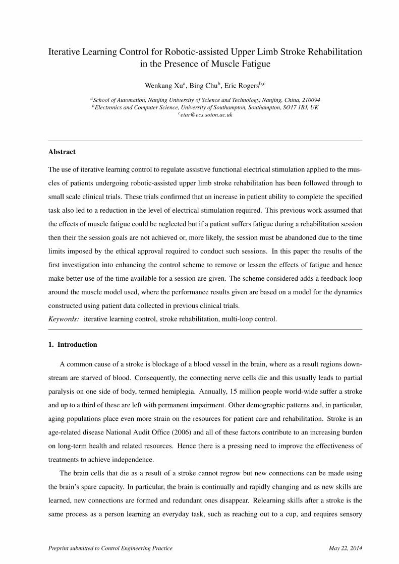
Figure 1: Kinematic system relationships, (a) combined system, (b) unweighing robotic device, and (c)human arm.
Figure 1 (a) shows the combined system and Fig. 1 (b) the kinematic structure of the exoskeleton sup-
port, where the joint variables qa = [ϑ1, ϑ2, ϑ3, ϑ4, ϑ5]T correspond to the measured joint angles, where
the parallelogram structure of the upper-limb section results in ϑ3 = −ϑ ′3. The human arm is shown in
Fig. 1 (c) and it is strapped to the support. Consequently within the necessary joint ranges there ex-
ists a unique bijective transformation between their coordinate sets, given by qu = fa (qa). Moreover,
qu = [ϑa, ϑb, ϑc, ϑd , ϑe]T contains the anthropomorphic variables shown in Fig. 1 (c).
5
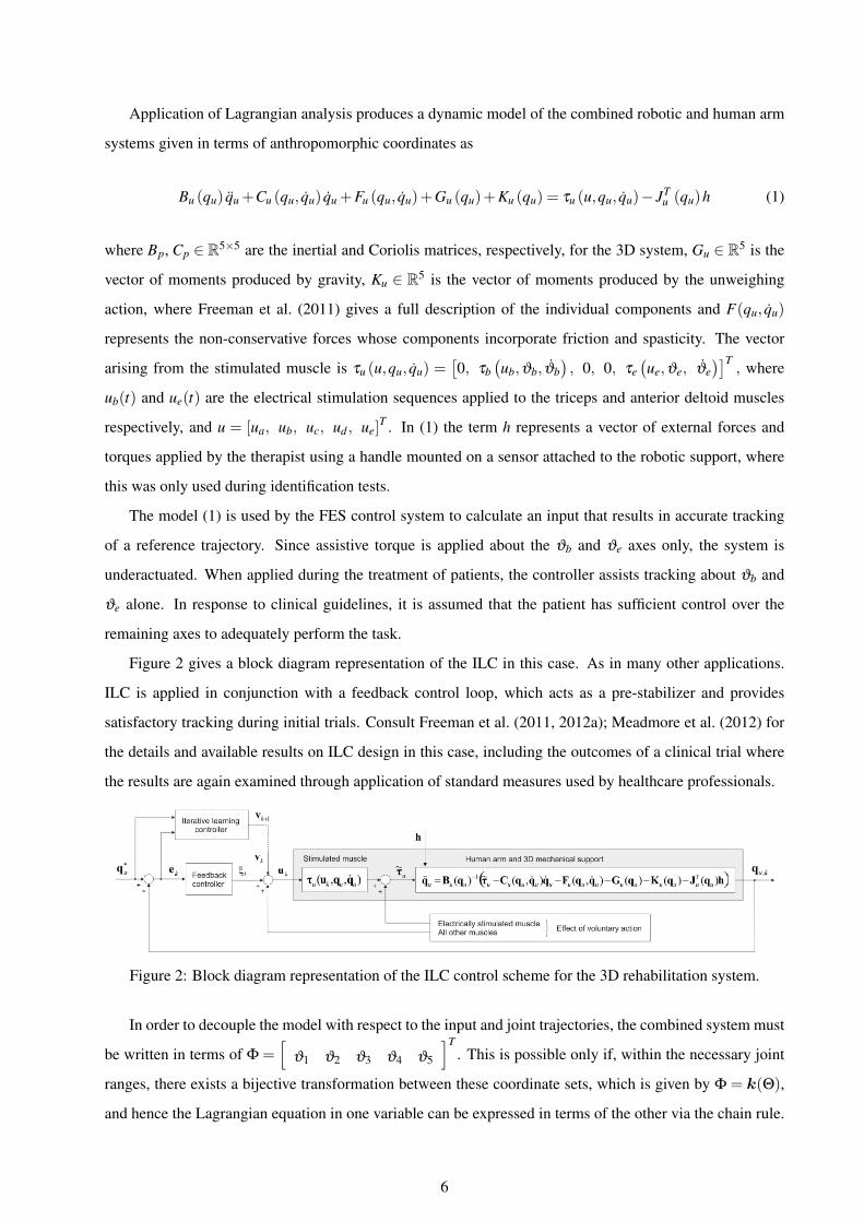
Application of Lagrangian analysis produces a dynamic model of the combined robotic and human arm
systems given in terms of anthropomorphic coordinates as
Bu (qu) qu +Cu (qu, qu) qu +Fu (qu, qu)+Gu (qu)+Ku (qu) = τu (u,qu, qu)− JTu (qu)h (1)
where Bp, Cp ∈ R5×5 are the inertial and Coriolis matrices, respectively, for the 3D system, Gu ∈ R5 is the
vector of moments produced by gravity, Ku ∈ R5 is the vector of moments produced by the unweighing
action, where Freeman et al. (2011) gives a full description of the individual components and F(qu, qu)
represents the non-conservative forces whose components incorporate friction and spasticity. The vector
arising from the stimulated muscle is τu (u,qu, qu) =[0, τb
(ub,ϑb, ϑb
), 0, 0, τe
(ue,ϑe, ϑe
)]T, where
ub(t) and ue(t) are the electrical stimulation sequences applied to the triceps and anterior deltoid muscles
respectively, and u = [ua, ub, uc, ud , ue]T . In (1) the term h represents a vector of external forces and
torques applied by the therapist using a handle mounted on a sensor attached to the robotic support, where
this was only used during identification tests.
The model (1) is used by the FES control system to calculate an input that results in accurate tracking
of a reference trajectory. Since assistive torque is applied about the ϑb and ϑe axes only, the system is
underactuated. When applied during the treatment of patients, the controller assists tracking about ϑb and
ϑe alone. In response to clinical guidelines, it is assumed that the patient has sufficient control over the
remaining axes to adequately perform the task.
Figure 2 gives a block diagram representation of the ILC in this case. As in many other applications.
ILC is applied in conjunction with a feedback control loop, which acts as a pre-stabilizer and provides
satisfactory tracking during initial trials. Consult Freeman et al. (2011, 2012a); Meadmore et al. (2012) for
the details and available results on ILC design in this case, including the outcomes of a clinical trial where
the results are again examined through application of standard measures used by healthcare professionals.
Figure 2: Block diagram representation of the ILC control scheme for the 3D rehabilitation system.
In order to decouple the model with respect to the input and joint trajectories, the combined system must
be written in terms of Φ =[
ϑ1 ϑ2 ϑ3 ϑ4 ϑ5
]T. This is possible only if, within the necessary joint
ranges, there exists a bijective transformation between these coordinate sets, which is given by Φ = k(Θ),
and hence the Lagrangian equation in one variable can be expressed in terms of the other via the chain rule.
6

The resulting combined model of the mechanical support and the human arm is
B(Φ)Φ+C(Φ,Φ)Φ+F (Φ,Φ)+G(Φ)+K(Φ) = τ (u,Φ,Φ)−JTh (Φ)h (2)
where experimental procedures to identify the parameters are given in Freeman et al. (2011).
2.3. Muscle Models and Fatigue
The response of a muscle to FES is a critical part of the application of ILC in robotic-assisted upper limb
stroke rehabilitation. This problem is also critical to many applications of FES assistive stimulation for both
upper and lower limb problems and the representations developed have considerable structural variations.
Of these, the Hill-type model Hill (1938), is widely used where the output torque produced by the stimu-
lated muscle is modeled as the product of three independent experimentally identified elements: the force
length property, the force velocity property and the nonlinear muscle activation dynamics under isometric
conditions. Consult Lynch & Popovic (2008) for comparative discussion, with supporting references, of
the various model structures currently available for this area. More recent results on the identification of a
model for muscle response to FES are given in Le et al. (2010, 2012).
In the research reported in this paper, the emphasis is on control system design and the muscle model
used is an approximation that captures many of the characteristics of the electrically stimulated muscle, in-
cluding the force-length property, force-velocity property, nonlinear recruitment and contraction dynamics.
The form of the first two experimentally measured factors is chosen to correspond with physiological obser-
vations Lum et al. (2004) and the activation dynamics is represented by a Hammerstein model consisting of
a static nonlinearity in series with linear dynamics.
The nonlinearity representing the isometric recruitment curve (IRC) is a static gain relation between
stimulus activation level and the steady-state output torque with the muscle held at a fixed length. Under
the isometric conditions, the response of a stimulated muscle the response can be modeled by a second-
order linear system that represents the dynamics of calcium diffusion to and from the sarcoplasmic reticula,
giving rise to contraction dynamics. Since controlled motions are typically smooth and slow, the effects of
inertia, velocity, and series elasticity are small and hence the isometric nonlinear activation dynamics are
the dominant muscle behavior Freeman et al. (2012a).
The activation dynamics are modeled by a Hammerstein structure consisting o af static nonlinearity,
hIRC(u), and linear activation dynamics hLAD(t). These, in turn, are linked to the steady-state torque Tm
produced by the static nonlinearity as
Tm = c1
∣∣∣∣ ec1u−1ec2u + c3
∣∣∣∣ (3)
where c1,c2 and c3 are muscle dependent parameters to be determined and u denotes the externally applied
stimulation impulse. The linear activation part converting Tm to the resultant torque T generated by the
7
muscle is modeled as a critically damped second-order linear system with undamped natural frequency ωn.
If the shape of the IRC is known and monotonic, its static gain characteristic can be canceled by placing
its inverse in the controller and this inverse recruitment map (IRM) can be either be stored as coefficients
of a polynomial approximation to the IRC or as a look-up table Durfee & MacLean (1989). Experimental
procedures to determine the parameters in this representation are given in Freeman et al. (2011).
One factor not considered yet in the application of ILC to regulate FES is muscle fatigue, which impedes
accurate movement control. The muscle is a nonlinear actuator and most of the control difficulties arise from
its time-varying IRC characteristics. The IRC of a muscle depends strongly on the past history of muscle
activation Durfee & MacLean (1989) and hence fatigue has a critical influence on this curve. If fatigue
occurs a substantial drop in magnitude in the IRC results and hence the performance of the control scheme
degrades. This problem is compounded by the higher frequency of the applied FES.
If muscle fatigue occurs for a patient in a clinical trial, the session must be stopped to allow recovery
and given that ethical approval only allows a finite time for a rehabilitation session with each patient, this
usually means it cannot recommence. In addition to the lost practice a premature end to a session can be
de-motivating in terms of the patient’s belief that improvement is possible. If the results so far are to move to
transfer beyond initial small clinical studies, one option is to investigate whether or not the control scheme
can be enhanced to counter these effects. This paper gives the first results in this area under two headings;
the inclusion of a model for the effects of fatigue and the inclusion of an additional feedback loop around
the muscle model.
Considerable research has been undertaken on the modeling and control of fatigued muscles but not in
the rehabilitation domain. The objective in this paper is to include a term, or model, to represent the effects
of fatigue on the performance of the ILC in this application and consider the enhancement of the control
system to lessen or overcome its effects. Modeling of fatigue has been considered in Chizeck et al. (1988,
1991), where the fatigue dynamics was found to be dependent on activation level, stimulation frequency
and recovery and was directly incorporated into the muscle dynamics. Other research Riener et al. (1996);
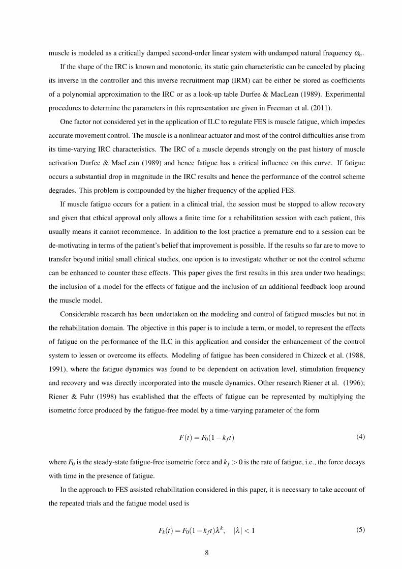
Riener & Fuhr (1998) has established that the effects of fatigue can be represented by multiplying the
isometric force produced by the fatigue-free model by a time-varying parameter of the form
F(t) = F0(1− k f t) (4)
where F0 is the steady-state fatigue-free isometric force and k f > 0 is the rate of fatigue, i.e., the force decays
with time in the presence of fatigue.
In the approach to FES assisted rehabilitation considered in this paper, it is necessary to take account of
the repeated trials and the fatigue model used is
Fk(t) = F0(1− k f t)λ k, |λ |< 1 (5)
8

where λ governs the influence of the fatigue from trial-to-trial. The premise is that the larger k f and λ the
greater the effects of fatigue on the muscle output. Both of these factors are muscle-dependent and therefore
have to be estimated for each patient. This model forms a starting point for the main focus of this paper,
i.e., to examine the effects of muscle fatigue on the performance of the ILC based regulation of the applied
stimulation. Use of this model will also serve as a benchmark to compare against the use of alternative
fatigue models, see also the conclusions section of this paper.
3. ILC Design
The control scheme developed in this paper is shown in Fig. 3 where the effects of fatigue are represented
as a disturbance on the muscle and regulated by a feedback loop placed around the muscle model and
the controller in this loop is termed the slave. In this arrangement, Φ∗ is the reference vector, Φk the
Φ∗Master Controller
ek ufbk uk
Slave Controller Muscleτ
fatigue
− Support & Arm−
ILCvk+1
Φk
Figure 3: Cascade control of supported human arm and muscle system.
measured output vector, u f bk and vk+1, are the outputs of the master controller and the ILC law on the kth
trial, respectively, and uk = u f bk + vk+1 is the input to the muscle control loop. This is a form of cascade
control, which has also been the subject of other ILC research outside the healthcare domain. For example,
in Tan et al. (2012) the convergence of cascaded ILC was addressed, where two ILC loops are cascaded.
Other research on the use of ILC plus feedback control for high-precision tracking performance has been
reported, e.g., Huang et al. (2014). For ease of presentation, this scheme will be referred to as cascade
control where relevant in the rest of this paper.
The remainder of this paper considers the case when the slave controller is a proportional gain in each
of the two channels and the master controller is proportional plus derivative (PD) as in previous work Free-
man et al. (2012a). In this first work, the aim is to establish if muscle fatigue can be compensated for by
augmenting the scheme used in the previous research reported in Freeman et al. (2012a); Meadmore et al.
(2012). Moreover, there is a strong case for initially considering the simplest possible addition to the ex-
isting scheme and hence the forms of the master and slave controllers considered. Other possibilities, such
as adding ILC to the inner loop, i.e., the slave controller loop, or other choices for the master and/or slave
controller, are left as topics for future research, see also the conclusions section of this paper.
Given the selection of the master controller, the tasks are to first construct a feedback linearizing control
input for the feedback inner loop formed that includes the slave controller and then design the ILC. These
tasks are detailed next, starting with the linearizing controller where trial-to-trial updating is not present and
9

hence the trial variable (subscript k) is omitted for ease of presentation.
Consider the muscle model discussed in the previous section, which can be written as the state-space
model
xi =
0 1
−ω2n −2ωn
xi +
0
1
hIRU,i(ui)
yi =[
ω2n 0
]xi, i = 2,5 (6)
where xi =[
xi,1 ii,2]T
, i = 2,5, ui, i = 1,2, are the applied stimulation impulses and the subscripts 2
and 5 correspond to the activated joint angles φ2 and φ5 respectively. If the IRC is assumed known and
monotonic, its static gain characteristic can be canceled by including its inverse as a gain term and the
linearizing controller is
u=
u2
u5
=
h−1IRC,2(w
2nx2,1 +2wnx2,2 +
v′2w2
n)
h−1IRC,5(w
2nx5,1 +2wnx5,2 +
v′5w2
n)
(7)
where v′2 and v′5 denote the muscle inputs to be designed.
Applying this controller cancels the static nonlinearity and next the slave controller is designed. This
master/slave control structure provides a more flexible structure than the single loop control methods, which
could lead to faster system response. Hence use as a preliminary controller to ILC design for this application
area. As there is no need to realize accurate tracking in the inner loop, a proportional controller in each
channel is used.
The slave controller gain is selected using trial-and-error and the master controller as in Freeman et al.
(2012a), with general guidance suggesting that in order to avoid resonance minimal difference between the
gains of slave and master controllers is the target. Simple block algebra gives that the slave controller loop
dynamics are described by the transfer-function matrix
Gmuscle(s) =
KsP2
s2+KsP2
0
0Ks
P5s2+Ks
P5
(8)
where Ksp2,Ks
p5are the proportional gains defining the slave controller. Also inputs to the controlled muscle
model (8) are the calculated torques from the master controller together with the torques generated by the
10
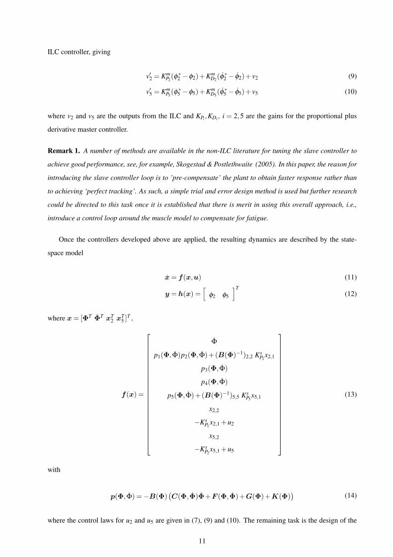
ILC controller, giving
v′2 = KmP2(φ ∗2 −φ2)+Km
D2(φ ∗2 − φ2)+ v2 (9)
v′5 = KmP5(φ ∗5 −φ5)+Km
D5(φ ∗5 − φ5)+ v5 (10)
where v2 and v5 are the outputs from the ILC and KPi ,KDi , i = 2,5 are the gains for the proportional plus
derivative master controller.
Remark 1. A number of methods are available in the non-ILC literature for tuning the slave controller to
achieve good performance, see, for example, Skogestad & Postlethwaite (2005). In this paper, the reason for
introducing the slave controller loop is to ’pre-compensate’ the plant to obtain faster response rather than
to achieving ‘perfect tracking’. As such, a simple trial and error design method is used but further research
could be directed to this task once it is established that there is merit in using this overall approach, i.e.,
introduce a control loop around the muscle model to compensate for fatigue.
Once the controllers developed above are applied, the resulting dynamics are described by the state-
space model
x= f(x,u) (11)
y = h(x) =[
φ2 φ5
]T(12)
where x= [ΦT ΦT xT2 x
T5 ]
T ,
f(x) =
Φ
p1(Φ,Φ)p2(Φ,Φ)+(B(Φ)−1)2,2 KsP2
x2,1
p3(Φ,Φ)
p4(Φ,Φ)
p5(Φ,Φ)+(B(Φ)−1)5,5 KsP5
x5,1
x2,2
−KsP1
x2,1 +u2
x5,2
−KsP2
x5,1 +u5
(13)
with
p(Φ,Φ) =−B(Φ)(C(Φ,Φ)Φ+F (Φ,Φ)+G(Φ)+K(Φ)
)(14)
where the control laws for u2 and u5 are given in (7), (9) and (10). The remaining task is the design of the
11

ILC law for v2 and v5 in (9) and (10), which is detailed next.
One obvious option at this stage is to again apply ILC phase-lead as in the planar task, i.e., design a
phase-lead ILC law for each of the muscles. This was considered but, as expected, the performance achieved
was inferior to that for the planar case. Moreover, for other 3D tasks it will be required to stimulate more
than two muscles and it is to be expected that the increase in dynamic complexity will require the design
of more advanced ILC laws. Hence the decision to consider model-based design, where as an exemplar
Newton method based ILC Lin et al. (2006) is used, see also the next section where the merits of this design
over gradient-based alternatives for this application are discussed.
The first step in Newton-based ILC design is to sample the dynamics and hence the uncontrolled dy-
namics are modeled by a discrete-time state-space model of the form
xk(t +1) = f [xk(t),vk(t)]
qu,k(t) = h[xk(t)](15)
where t = 0,1,2, . . . ,N−1 is the sample number, xk(t) is the state vector, vk(t) = [v2,k(t) v5,k(t)]T is the
control input to be designed, and N = T/Ts +1 with Ts the sampling frequency. Introducing the vectors
vk = [vk(0)T ,vk(1)T , . . . ,vk(N−1)T ]T
qu,k = [qu,k(0)T ,qu,k(1)T , . . . ,qu,k(N−1)T ]T (16)
and the reference vector
q∗u = [q∗u(0)T ,q∗u(1)
T , . . . ,q∗u(N−1)T ]T (17)
the Newton method based ILC update takes the form
vk+1 = vk +g′(vk)
−1ek (18)
where ek = q∗u−qu,k is the tracking error. The term g′(vk) is equivalent to linearizing the dynamics around
vk, with the system qu = g′(vk)v corresponding to the linear time-varying, denoted LTV, system
x(t +1) = A(t)x(t)+B(t)v(t)
qu(t) = C(t)x(t)+D(t)v(t) t = 0,1, . . . ,N−1(19)
with
A(t) =(
∂f
∂x
)vk(t),xk(t)
, B(t) =(
∂f
∂vk
)vk(t),xk(t)
C(t) =(
∂h
∂x
)vk(t),xk(t)
, D(t) =(
∂h
∂vk
)vk(t),xk(t)
12
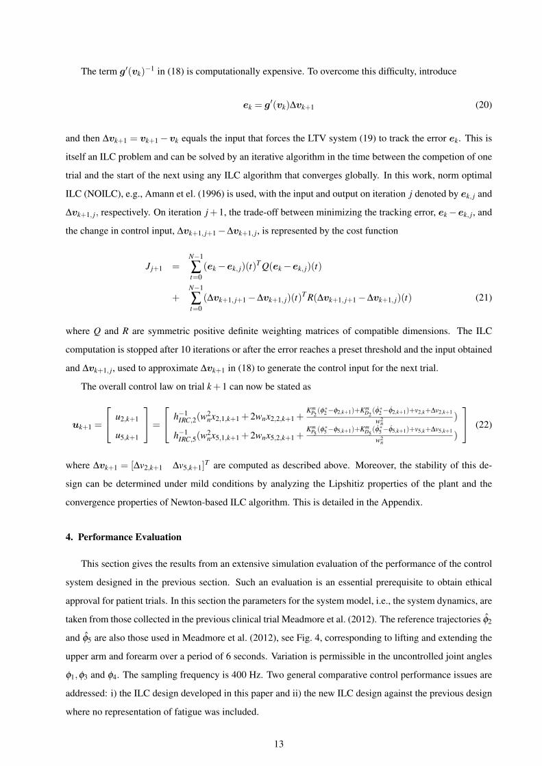
The term g′(vk)−1 in (18) is computationally expensive. To overcome this difficulty, introduce
ek = g′(vk)∆vk+1 (20)
and then ∆vk+1 = vk+1−vk equals the input that forces the LTV system (19) to track the error ek. This is
itself an ILC problem and can be solved by an iterative algorithm in the time between the competion of one
trial and the start of the next using any ILC algorithm that converges globally. In this work, norm optimal
ILC (NOILC), e.g., Amann et el. (1996) is used, with the input and output on iteration j denoted by ek, j and
∆vk+1, j, respectively. On iteration j+1, the trade-off between minimizing the tracking error, ek−ek, j, and
the change in control input, ∆vk+1, j+1−∆vk+1, j, is represented by the cost function
J j+1 =N−1
∑t=0
(ek−ek, j)(t)T Q(ek−ek, j)(t)
+N−1
∑t=0
(∆vk+1, j+1−∆vk+1, j)(t)T R(∆vk+1, j+1−∆vk+1, j)(t) (21)
where Q and R are symmetric positive definite weighting matrices of compatible dimensions. The ILC
computation is stopped after 10 iterations or after the error reaches a preset threshold and the input obtained
and ∆vk+1, j, used to approximate ∆vk+1 in (18) to generate the control input for the next trial.
The overall control law on trial k+1 can now be stated as
uk+1 =
u2,k+1
u5,k+1
=
h−1IRC,2(w
2nx2,1,k+1 +2wnx2,2,k+1 +
KmP2(φ∗2−φ2,k+1)+Km
D2(φ∗2−φ2,k+1)+v2,k+∆v2,k+1
w2n
)
h−1IRC,5(w
2nx5,1,k+1 +2wnx5,2,k+1 +
KmP5(φ∗5−φ5,k+1)+Km
D5(φ∗5−φ5,k+1)+v5,k+∆v5,k+1
w2n
)
(22)
where ∆vk+1 = [∆v2,k+1 ∆v5,k+1]T are computed as described above. Moreover, the stability of this de-
sign can be determined under mild conditions by analyzing the Lipshitiz properties of the plant and the
convergence properties of Newton-based ILC algorithm. This is detailed in the Appendix.
4. Performance Evaluation
This section gives the results from an extensive simulation evaluation of the performance of the control
system designed in the previous section. Such an evaluation is an essential prerequisite to obtain ethical
approval for patient trials. In this section the parameters for the system model, i.e., the system dynamics, are
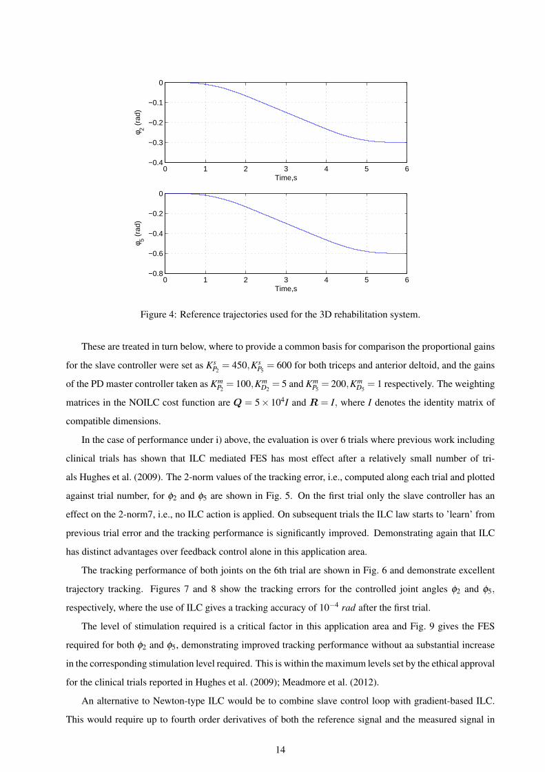
taken from those collected in the previous clinical trial Meadmore et al. (2012). The reference trajectories φ2
and φ5 are also those used in Meadmore et al. (2012), see Fig. 4, corresponding to lifting and extending the
upper arm and forearm over a period of 6 seconds. Variation is permissible in the uncontrolled joint angles
φ1,φ3 and φ4. The sampling frequency is 400 Hz. Two general comparative control performance issues are
addressed: i) the ILC design developed in this paper and ii) the new ILC design against the previous design
where no representation of fatigue was included.
13
0 1 2 3 4 5 6−0.4
−0.3
−0.2
−0.1
0
Time,s
φ 2 (ra
d)
0 1 2 3 4 5 6−0.8
−0.6
−0.4
−0.2
0
Time,s
φ 5 (ra
d)
Figure 4: Reference trajectories used for the 3D rehabilitation system.
These are treated in turn below, where to provide a common basis for comparison the proportional gains
for the slave controller were set as KsP2= 450,Ks
P5= 600 for both triceps and anterior deltoid, and the gains
of the PD master controller taken as KmP2= 100,Km
D2= 5 and Km
P5= 200,Km
D5= 1 respectively. The weighting
matrices in the NOILC cost function are Q = 5× 10⁴I and R = I, where I denotes the identity matrix of
compatible dimensions.
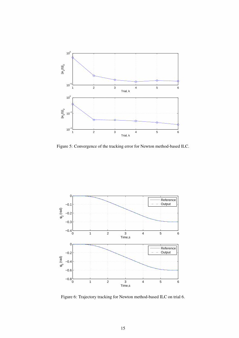
In the case of performance under i) above, the evaluation is over 6 trials where previous work including
clinical trials has shown that ILC mediated FES has most effect after a relatively small number of tri-
als Hughes et al. (2009). The 2-norm values of the tracking error, i.e., computed along each trial and plotted
against trial number, for φ2 and φ5 are shown in Fig. 5. On the first trial only the slave controller has an
effect on the 2-norm7, i.e., no ILC action is applied. On subsequent trials the ILC law starts to ’learn’ from
previous trial error and the tracking performance is significantly improved. Demonstrating again that ILC
has distinct advantages over feedback control alone in this application area.
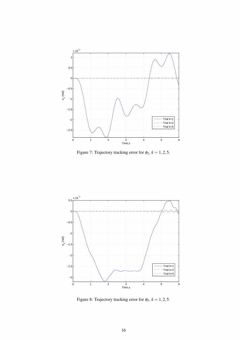
The tracking performance of both joints on the 6th trial are shown in Fig. 6 and demonstrate excellent
trajectory tracking. Figures 7 and 8 show the tracking errors for the controlled joint angles φ2 and φ5,
respectively, where the use of ILC gives a tracking accuracy of 10−4 rad after the first trial.
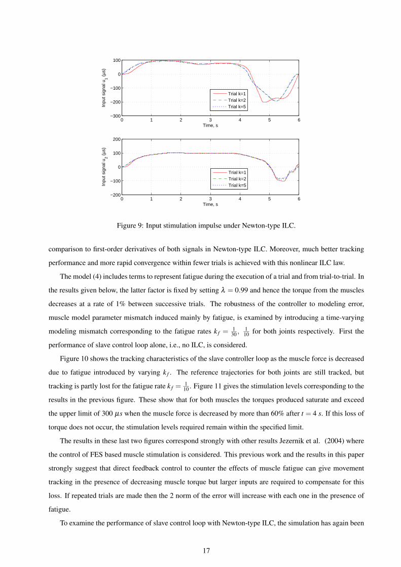
The level of stimulation required is a critical factor in this application area and Fig. 9 gives the FES
required for both φ2 and φ5, demonstrating improved tracking performance without aa substantial increase
in the corresponding stimulation level required. This is within the maximum levels set by the ethical approval
for the clinical trials reported in Hughes et al. (2009); Meadmore et al. (2012).
An alternative to Newton-type ILC would be to combine slave control loop with gradient-based ILC.
This would require up to fourth order derivatives of both the reference signal and the measured signal in
14
1 2 3 4 5 610
−5
100
Trial, k
||e2(t
)|| 2
1 2 3 4 5 610
−4
10−2
100
Trial, k
||e5(t
)|| 2
Figure 5: Convergence of the tracking error for Newton method-based ILC.
0 1 2 3 4 5 6−0.4
−0.3
−0.2
−0.1
0
Time,s
φ 2 (ra
d)
0 1 2 3 4 5 6−0.8
−0.6
−0.4
−0.2
0
Time,s
φ 5 (ra
d)
ReferenceOutput
ReferenceOutput
Figure 6: Trajectory tracking for Newton method-based ILC on trial 6.
15
0 1 2 3 4 5 6
−2.5
−2
−1.5
−1
−0.5
0
0.5
1
x 10−3
Time,s
e 2 (ra
d)
Trial k=1Trial k=2Trial k=5
Figure 7: Trajectory tracking error for φ2, k = 1,2,5.
0 1 2 3 4 5 6
−3
−2.5
−2
−1.5
−1
−0.5
0
0.5x 10
−3
Time,s
e 5 (ra
d)
Trial k=1Trial k=2Trial k=5
Figure 8: Trajectory tracking error for φ5, k = 1,2,5.
16
0 1 2 3 4 5 6−300
−200
−100
0
100
Time, s
Inpu
t sig
nal u
1 (µs
)
0 1 2 3 4 5 6−200
−100
0
100
200
Time, s
Inpu
t sig
nal u
2 (µs
)
Trial k=1Trial k=2Trial k=5
Trial k=1Trial k=2Trial k=5
Figure 9: Input stimulation impulse under Newton-type ILC.
comparison to first-order derivatives of both signals in Newton-type ILC. Moreover, much better tracking
performance and more rapid convergence within fewer trials is achieved with this nonlinear ILC law.
The model (4) includes terms to represent fatigue during the execution of a trial and from trial-to-trial. In
the results given below, the latter factor is fixed by setting λ = 0.99 and hence the torque from the muscles
decreases at a rate of 1% between successive trials. The robustness of the controller to modeling error,
muscle model parameter mismatch induced mainly by fatigue, is examined by introducing a time-varying
modeling mismatch corresponding to the fatigue rates k f =130 ,
110 for both joints respectively. First the
performance of slave control loop alone, i.e., no ILC, is considered.
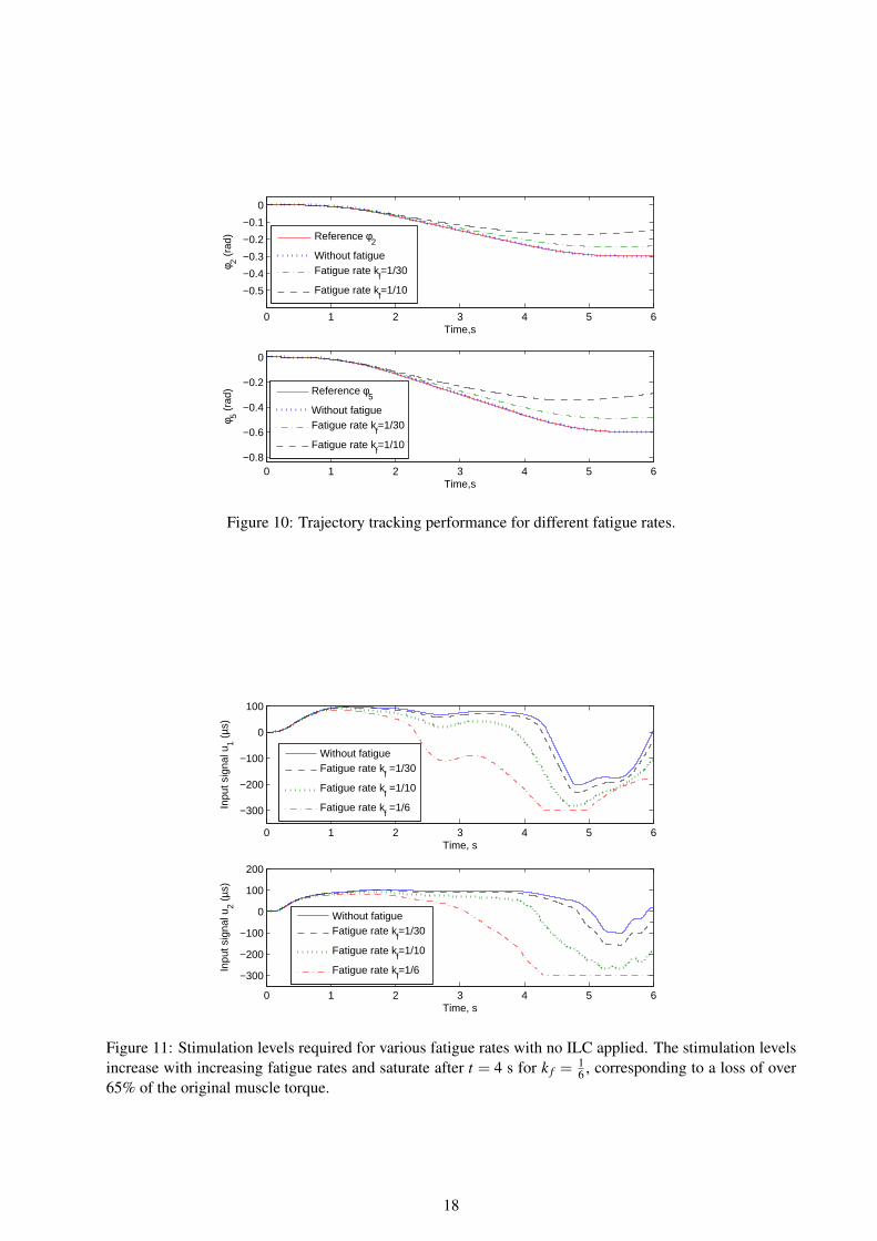
Figure 10 shows the tracking characteristics of the slave controller loop as the muscle force is decreased
due to fatigue introduced by varying k f . The reference trajectories for both joints are still tracked, but
tracking is partly lost for the fatigue rate k f =1
10 . Figure 11 gives the stimulation levels corresponding to the
results in the previous figure. These show that for both muscles the torques produced saturate and exceed
the upper limit of 300 µs when the muscle force is decreased by more than 60% after t = 4 s. If this loss of
torque does not occur, the stimulation levels required remain within the specified limit.
The results in these last two figures correspond strongly with other results Jezernik et al. (2004) where
the control of FES based muscle stimulation is considered. This previous work and the results in this paper
strongly suggest that direct feedback control to counter the effects of muscle fatigue can give movement
tracking in the presence of decreasing muscle torque but larger inputs are required to compensate for this
loss. If repeated trials are made then the 2 norm of the error will increase with each one in the presence of
fatigue.
To examine the performance of slave control loop with Newton-type ILC, the simulation has again been
17
0 1 2 3 4 5 6
−0.5
−0.4
−0.3
−0.2
−0.1
0
Time,s
φ 2 (ra
d)
0 1 2 3 4 5 6−0.8
−0.6
−0.4
−0.2
0
Time,s
φ 5 (ra
d)
Reference φ2
Without fatigueFatigue rate k
f=1/30
Fatigue rate kf=1/10
Reference φ5
Without fatigueFatigue rate k
f=1/30
Fatigue rate kf=1/10
Figure 10: Trajectory tracking performance for different fatigue rates.
0 1 2 3 4 5 6
−300
−200
−100
0
100
Time, s
Inpu
t sig
nal u
1 (µs
)
0 1 2 3 4 5 6
−300
−200
−100
0
100
200
Time, s
Inpu
t sig
nal u
2 (µs
)
Without fatigueFatigue rate k
f =1/30
Fatigue rate kf =1/10
Fatigue rate kf =1/6
Without fatigueFatigue rate k
f=1/30
Fatigue rate kf=1/10
Fatigue rate kf=1/6
Figure 11: Stimulation levels required for various fatigue rates with no ILC applied. The stimulation levelsincrease with increasing fatigue rates and saturate after t = 4 s for k f =
16 , corresponding to a loss of over
65% of the original muscle torque.
18
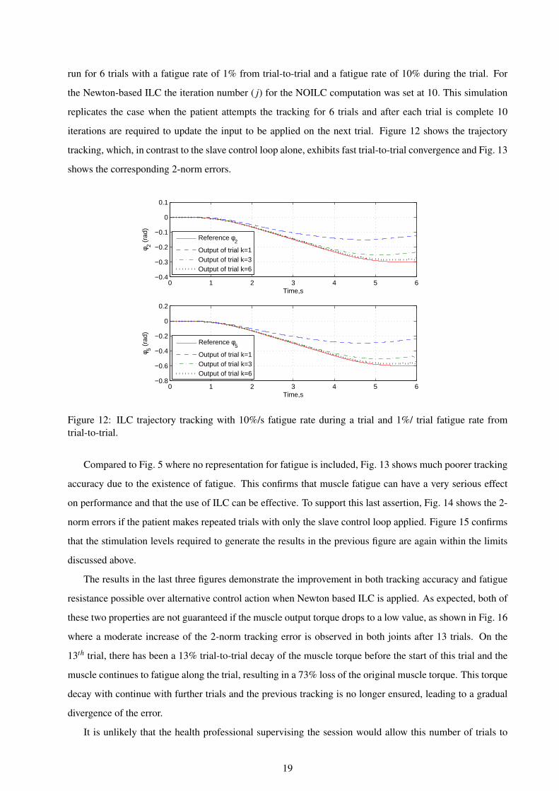
run for 6 trials with a fatigue rate of 1% from trial-to-trial and a fatigue rate of 10% during the trial. For
the Newton-based ILC the iteration number ( j) for the NOILC computation was set at 10. This simulation
replicates the case when the patient attempts the tracking for 6 trials and after each trial is complete 10
iterations are required to update the input to be applied on the next trial. Figure 12 shows the trajectory
tracking, which, in contrast to the slave control loop alone, exhibits fast trial-to-trial convergence and Fig. 13
shows the corresponding 2-norm errors.
0 1 2 3 4 5 6−0.4
−0.3
−0.2
−0.1
0
0.1
Time,s
φ 2 (ra
d)
0 1 2 3 4 5 6−0.8
−0.6
−0.4
−0.2
0
0.2
Time,s
φ 5 (ra
d)
Reference φ2
Output of trial k=1Output of trial k=3Output of trial k=6
Reference φ5
Output of trial k=1Output of trial k=3Output of trial k=6
Figure 12: ILC trajectory tracking with 10%/s fatigue rate during a trial and 1%/ trial fatigue rate fromtrial-to-trial.
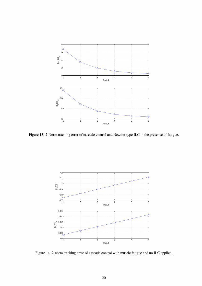
Compared to Fig. 5 where no representation for fatigue is included, Fig. 13 shows much poorer tracking
accuracy due to the existence of fatigue. This confirms that muscle fatigue can have a very serious effect
on performance and that the use of ILC can be effective. To support this last assertion, Fig. 14 shows the 2-
norm errors if the patient makes repeated trials with only the slave control loop applied. Figure 15 confirms
that the stimulation levels required to generate the results in the previous figure are again within the limits
discussed above.
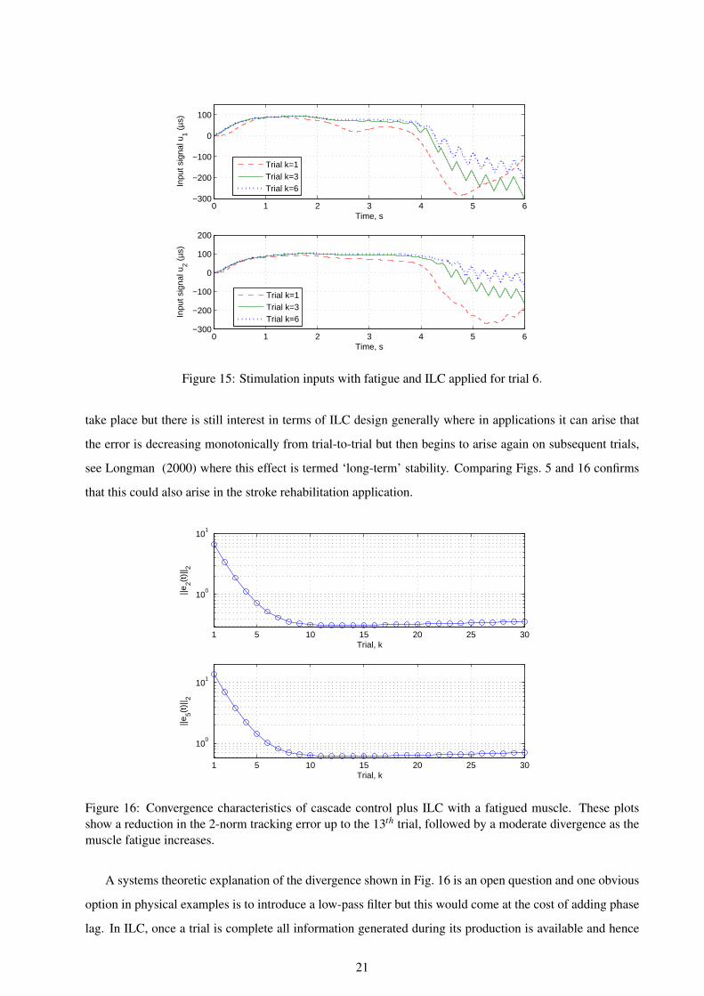
The results in the last three figures demonstrate the improvement in both tracking accuracy and fatigue
resistance possible over alternative control action when Newton based ILC is applied. As expected, both of
these two properties are not guaranteed if the muscle output torque drops to a low value, as shown in Fig. 16
where a moderate increase of the 2-norm tracking error is observed in both joints after 13 trials. On the
13th trial, there has been a 13% trial-to-trial decay of the muscle torque before the start of this trial and the
muscle continues to fatigue along the trial, resulting in a 73% loss of the original muscle torque. This torque
decay with continue with further trials and the previous tracking is no longer ensured, leading to a gradual
divergence of the error.
It is unlikely that the health professional supervising the session would allow this number of trials to
19
1 2 3 4 5 60
2
4
6
8
Trial, k
||e2(t
)|| 2
1 2 3 4 5 60
5
10
15
Trial, k
||e5(t
)|| 2
Figure 13: 2-Norm tracking error of cascade control and Newton-type ILC in the presence of fatigue.
1 2 3 4 5 66.7
6.8
6.9
7
7.1
7.2
Trial, k
||e2(t
)|| 2
1 2 3 4 5 613.6
13.8
14
14.2
14.4
14.6
Trial, k
||e5(t
)|| 2
Figure 14: 2-norm tracking error of cascade control with muscle fatigue and no ILC applied.
20
0 1 2 3 4 5 6−300
−200
−100
0
100
Time, s
Inpu
t sig
nal u
1 (µs
)
0 1 2 3 4 5 6−300
−200
−100
0
100
200
Time, s
Inpu
t sig
nal u
2 (µs
)
Trial k=1Trial k=3Trial k=6
Trial k=1Trial k=3Trial k=6
Figure 15: Stimulation inputs with fatigue and ILC applied for trial 6.
take place but there is still interest in terms of ILC design generally where in applications it can arise that
the error is decreasing monotonically from trial-to-trial but then begins to arise again on subsequent trials,
see Longman (2000) where this effect is termed ‘long-term’ stability. Comparing Figs. 5 and 16 confirms
that this could also arise in the stroke rehabilitation application.
1 5 10 15 20 25 30
100
101
Trial, k
||e2(t
)|| 2
1 5 10 15 20 25 30
100
101
Trial, k
||e5(t
)|| 2
Figure 16: Convergence characteristics of cascade control plus ILC with a fatigued muscle. These plotsshow a reduction in the 2-norm tracking error up to the 13th trial, followed by a moderate divergence as themuscle fatigue increases.
A systems theoretic explanation of the divergence shown in Fig. 16 is an open question and one obvious
option in physical examples is to introduce a low-pass filter but this would come at the cost of adding phase
lag. In ILC, once a trial is complete all information generated during its production is available and hence
21
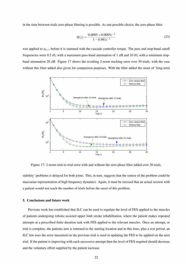
in the time between trials zero-phase filtering is possible. As one possible choice, the zero-phase filter
H(z) =0.0095+0.0095z−1
1−0.981z−1(23)
was applied to uk+1 before it is summed with the cascade controller torque. The pass and stop-band cutoff
frequencies were 0.5 Hz with a maximum pass-band attenuation of 1 dB and 10 Hz with a minimum stop-
band attenuation 20 dB. Figure 17 shows the resulting 2-norm tracking error over 30 trials, with the case
without this filter added also given for comparison purposes. With the filter added the onset of ‘long-term
1 5 10 15 20 25 30
100
Trial, k
||e2(t
)|| 2
1 5 10 15 20 25 30
100
101
Trial, k
||e5(t
)|| 2
Zero−phase filterWithout filter
Zero−phase filterWithout filter
divergence after 13 trials divergence after 17 trials
divergence after 13 trials divergence after 21 trials
Figure 17: 2-norm trial-to-trial error with and without the zero-phase filter added over 30 trials.
stability’ problems is delayed for both joints. This, in turn, suggests that the source of the problem could be
inaccurate representation of high frequency dynamics. Again, it must be stressed that an actual session with
a patient would not reach the number of trials before the onset of this problem.
5. Conclusions and future work
Previous work has established that ILC can be used to regulate the level of FES applied to the muscles
of patients undergoing robotic-assisted upper limb stroke rehabilitation, where the patient makes repeated
attempts at a prescribed finite duration task with FES applied to the relevant muscles. Once an attempt, or
trial is complete, the patients arm is returned to the starting location and in this time, plus a rest period, an
ILC law uses the error measured on the previous trial is used in updating the FES to be applied on the next
trial. If the patient is improving with each successive attempt then the level of FES required should decrease
and the voluntary effort supplied by the patient increase.
22

This latter property has been detected in clinical trials for both planar and 3D tasks where a prescribed
path, or reference signal, for the patient to follow was provided. This ‘proof of concept’ provides a starting
point for the onward development of this general approach to tasks that even more closely resemble daily
living tasks, such reaching and switching on or off a light switch, where a precise reference signal to follow
is not imposed. This paper has addressed another critical factor not considered in previous work, i.e., the
effects of muscle fatigue that can arise for a number of reasons and, in particular, since the applied FES is at
higher frequency.
If a patient suffers from fatigue during a session then it must be halted and given that ethical approval
limits the time a patient can spend in a session the most likely outcome is that the session must be terminated.
This raises the question of whether or not it is possible to include a representation of fatigue in the model
used for ILC design and this paper gives the first results in this direction where a form of cascade control in
the form of a master slave arrangement is employed.
The slave controller is applied in a feedback loop around the muscle model and the master controller in
an outer feedback loop around the muscle model and the arm model As common in many applications of
ILC, this control action is applied following the design and application of a feedback control loop. To obtain
ethical approval for a clinical trial it is first necessary to undertake a detailed simulation based investigation
of the controlled dynamics, where the results in this paper use a biomechanical model constructed from
patient data collected in the earlier clinical trials.
Overall, the results in this paper confirm that the control arrangement used is capable of representing
and compensating for the effects of muscle fatigue in this area. This paper also shows that advanced control
law design can be considered for cases where simple structure laws, such as phase-lead ILC, have to be
replaced by more advanced laws. For the 3D control task considered in this paper, the phase-lead ILC is still
applicable but better performance results from the use of an advanced algorithm, in this work Newton-based
ILC. As the tasks move closer to those in everyday life the dynamic complexity increases with the need to
stimulate different combinations of muscles and hence the phase-lead and other simple structure ILC laws
must be replaced from the start.
Much further work remains to be done at both the control systems design/evaluation before clinical
trials can be considered. For example, the results in this paper have used simple structure master and slave
controllers where the objective was to make the simplest possible changes to designs that have been clinically
evaluated. Another aspect to examine here would, based on the ILC for engineering applications literature,
be to add ILC to the inner loop. Also the question of assigning the relative effort or the master and slave
controllers should be addressed, together with the use of alternatives to Newton-based ILC. Further research
is also required on the fatigue model itself. An alternative approach to representing the effects of fatigue in
this ILC application would be to treat it as a trial-dependent disturbance and aim to design a trial dependent
learning gain. Some results on this approach in the engineering literature can be found in, e.g. Chen &
23

Moore (2002).
Appendix A. Stability analysis of the ILC design
The stability of the ILC design in this paper can be analyzed using the following result, which is a
restatement of the a result in Lin et al. (2006) on the convergence properties of the Newton-based ILC
method.
Proposition Lin et al. (2006): Write the tracking error system in operator form as e(t)= [Gu(t)]. Suppose
also that G is Frechet-differentiable and that there exists γ > 0 such that
‖G′(a)−G′(b)‖ ≤ γ‖a−b‖ (A.1)
where || · || denotes the norm on the underling function space and the the induced operator norm. As-
sume also that there exists an initial input u0 satisfying ‖G′(u0)−1‖ < β and that βγη ≤ 1/2, where
η = ‖G′(u0)−1G(u0)‖. Then the Newton-based ILC method
uk+1 = uk +G′(uk)−1ek
is well defined and converges to a solution u∗ of G(u) = 0 and thus perfect tracking is achieved.
For the design in this paper, the system y(t) = Gu(t) consists of the linearized muscle model, master
and slave controllers (proportional and PD controllers, respectively) and a nonlinear passive Euler-Lagrange
dynamic model of the robotic arm which is known to be a Lipschitz system Jezernik et al. (2004). As a
result, there exists γ such that (A.1) is satisfied. Moreover, G′(u0)−1 is a linearized system operating on
L2[0,T ] where T is the trial length and hence it is also bounded. Moreover, when u0 = u∗, η = 0 and hence
by continuity there exists an u0 such that βγη < 1/2. Consequently, stability and hence trial-to-trial error
convergence to zero is guaranteed.
References
Ahn, H. S., Chen, Y. Q., & Moore, K. L. (2007). Iterative learning control: Brief survey and categorization.
IEEE Transactions on Systems Man and Cybernetics, Part C: Applications and Reviews, 37(6), 1109–
1121.
Abbas, J. J., Chizeck, H. J. (1995). Neural network control of functional neuromuscular systems: Computer
simulation studies. IEEE Transactions on Biomedical Engineering, 42(11), 1117–1127.
Amann, N., Owens, D. H., Rogers, E. (1996). Iterative learning control for discrete time systems with
exponential rate of convergence. IEE Proceedings: Control Theory and Applications, 143, 217–224.
24
Bristow, D. A., Tharayil, M., Alleyne, A. G. (2006). Iterative learning control: A learning-based method for
high performance tracking control. IEEE Control Systems Magazine, 26(3), 96–114.
Chen, Y.Q., Moore, K. L. (2002). Harnessing the nonrepetitiveness in iterative learning control. 41st IEEE
Conference on Decision and Control, 3350–3355.
Chizeck, H. J., Crago, P. E., Kofman, L. S. (1989). Robust closed-loop control of isometric muscle force
using pulsewidth modulation. IEEE Transactions on Biomedical Engineering, 35(7), 510–517.
Chizeck, H. J., Lan, N., Palmieri, L. S., Crago, P. E. (1991). Feedback control of electrically stimulated mus-
cle using simultaneous pulse width and stimulus period modulation. IEEE Transactions on Biomedical
Engineering, 38(12), 1224–1234.
De Kroon, J. R., Ijzerman, M. J., Chae, J. J., Lankhorst, G. J., Zilvold, G. (2005). Relation between stimula-
tion characteristics and clinical outcome in studies using electrical stimulation to improve motor control
of the upper extremity in stroke. Journal of Rehabilitation Medicine, 37(2), 65–74.
Dou, H., Tan, K. K., Lee, T. H., Zhou, Z. 1999. Iterative learning feedback control of human limbs via
functional electrical stimulation. Control Engineering Practice, 7(3): 315–325.
Durfee, W. K., MacLean, K. E. (1989). Methods for estimating isometric recruitment curves of electrically
stimulated muscles. IEEE Transactions on Biomedical Engineering, 35(7), 654–667.
Dimitra, B. (2008). Feedback control of a high level upper extremity neuroprosthesis. PhD thesis, Case
Western Reverse University.
Freeman, C. T., Rogers, E., Hughes, A.-M., Burridge, J. H., Meadmore, K. L. (2012a). Iterative learning
control in healthcare: electrical stimulation and robotic-assisted upper limb stroke rehabilitation. IEEE
Control Systems Magazine, 32(1), 18–43.
Freeman, C. T., Hughes, A.-M., Burridge, J. H., Chappell, P. H., Lewin, P. L., Rogers, E. (2009a). Iterative
learning control of FES applied to the upper extremity for rehabilitation. Control Engineering Practice,
17(3), 368–381.
Freeman, C. T., Hughes, A.-M., Burridge, J. H., Chappell, P. H., Lewin, P. L., Rogers, E. (2009b). A model
of the upper extremity using FES for stroke rehabilitation. Journal of Biomechanics, 131(3), 031011-1–
031011-12.
Freeman, C. T., Hughes, A.-M., Burridge, J. H., Chappell, P. H., Lewin, P. L., Rogers, E. (2009c). A robotic
workstation for stroke rehabilitation of the upper extremity using FES. Medical Engineering and Physics,
31(3), 364–373.
25
Freeman, C. T., Tong, D., Meadmore, K. L., Cai, Z., Rogers, E., Hughes, A.-M., Burridge, J. H. (2011).
Phase-lead iterative learning control algorithms for functional electrical stimulation based stroke rehabil-
itation. Proceedings of the Institution of Mechanical Engineers, Part I, Journal of Systems and Control
Engineering, 225(6), 850–859.
Freeman, C. T., Tong, D., Meadmore, K. L., Hughes, A.M., Rogers, E., Burridge, J. H. (2012b). FES based
rehabilitation of the upper limb using input/output linearization and ILC. American Control Conference,
4825–4830.
Hendricks, H. T., van Limbeek, J.,A. C. Geurts, A, C., and Zwarts, M. J. (2002). Motor recovery after stroke:
a systematic review of the literature. Archieves of Physical Medicene and Rehabilitation, 83, 1629–1637.
Hill, A. V. (1938). Then heat of shortening and the dynamic constants of a muscle. Proceedings of the Royal
Society of London, 126, 136–195.
Huang, D., Xu, J-X, Venkataramanan, V., Huynh, T. C. T. (2014) High-performance tracking of piezoelectric
positioning stage using current-cycle iterative learning control with gain scheduling. IEEE Transactions
on Industrial Electronics, 61(2) 1085–1098.
Hughes, A.-M., Freeman, C. T., Burridge, J. H., Chappell, P. H., Lewin, P. L., Rogers, E. (2009). Feasi-
bility of iterative learning control mediated by functional electrical stimulation for reaching after stroke.
Neurorehabilitation and Neural Repair, 23(6), 559–568.
Jezernik, S., Wassink, R. G., Keller, T. (2004). Sliding mode closed-loop control of FES: controlling the
shank movement. IEEE Transactions on Biomedical Engineering, 51(2), 263–272.
Krebs, H. I., Palazzolo, J. J., Dipietro, L., Ferraro, M., Krol, J., Rannekleiv, K., Volpe, B. T., Hogan,
N. (2003). Rehabilitation robotics: performance-based progressive robotic-assisted therapy. Autonomous
Robots, 15(1), 7–20.
Lan, N. (2002). Stability analysis for postural control in a two-joint limb system. IEEE Transactions on
Neural Systems and Rehabilitation Engineering, 10(4), 249–259.
Le, F., Markovsky, I., Freeman, C. T., Rogers, E. (2010). Identification of electrically stimulated muscle
models of stroke patients. Control Engineering Practice, 18(4), 396–407.
Le, F., Markovsky, I., Freeman, C. T., Rogers, E. (2012). Recursive identification of Hammerstein systems
with application to electrically stimulated muscle. Control Engineering Practice, 20(4), 386–396.
Lin, T., Owens, D. H., Hatonen, J. (2006). Newton-based iterative learning control for discrete nonlinear
systems. International Journal of Control, 79(10), 1263–1276.
26
Longman, R. W.: Iterative learning control and repetitive control for engineering practice. International
Journal of Control, 73(10): 930–954.
Lynch, C. L., Popovic, M. R. (2008). Functional electrical stimulation: closed-loop control of induced
muscle contractions. IEEE Control Systems Magazine, 28(2), 40–50.
Lum, P. S., Burgar, C. G., Shor, P. C. (2004). Evidence for improved muscle activation patterns after retrain-
ing of reaching movements with the mime robotic system in subjects with post-stroke hemiparesis. IEEE
Transactions on Neural Systems and Rehabilitation Engineering, 12(2), 186–194.
Meadmore, K. L., Hughes, A.-M., Freeman, C. T., Cai, Z., Tong, D., Burridge, J. H., Rogers, E. (2012).
Function electrical stimulation mediated by iterative learning control and 3D robotics reduces motor im-
pairment in chronic stroke. Journal of Neuroengineering and Rehabilitation, doi: 10.1186/1743-0003-9-
32.
National Audit Office, Reducing brain damage: faster access to better stroke care. HC 452, 2004. Available
at htt p : //www.nao.org.uk/publications/0506/reducingbraindamage.aspx.
Riener, R., Quinternt, J., Schmidt, G. (1996). Biomechanical model of the human knee evaluated by muscu-
lar stimulation. Journal of Biomechanics, 29(9), 1157–1167.
Riener, R., Fuhr, T. (1998). Patient-driven control of FES-supported standing up: a simulation study. IEEE
Transactions on Rehabilitation Engineering, 6(2), 113–124.
Rushton, D. N. (2003). Functional electrical stimulation and rehabilitation–an hypothesis. Medical Engi-
neering and Physics, 1, 75–78.
van der Putten, J. J. M. F., Hobart, J. C., Freeman, J. A., Thompson, A. J. (1999). Measuring change in
disability after inpatient rehabilitation: comparison of the responsiveness of the Barthel index and the
functional independence measure. Journal of Neurology, Neurosurgery & Psychiatry, 66, 480–484.
Skogestad, S., Postlethwaite, I. (2005). Multivariable Feedback Control: Analysis and Design, Wiley, 2005.
Tan, Y., Dai, H-H., Huang, D., Xu, J-X. (2012) Unified iterative learning control schemes for nonlinear
dynamic systems with nonlinear input uncertainties. Automatica, 48(12), 3173–3182.
27