itisikorsky helicopter flight theory for pilots and mechanics by john r. montgomery i' i...
TRANSCRIPT

I. ItI
REFERENCE BOOK
SIKORSKY HELICOPTER FLIGHT THEORYFOR PILOTS AND MECHANICS
IN SUPPORT OF
THEORY OF FLIGHT
S50 -7715-8
SEP1 •1982
JANUARY 1976
A
LJ UNITED STATES ARMY AVIATION CENTER
FCRT RUCKER, ALABAMA
f,• ,o•,,nt ho b•n oppvovld 82 08 09 09 2f')T public rokCi'o afid nala; itsdti-hidbioion iR mililmlocl .

USikorsky Aircraft DIVISION OU
STRATFORD, CONNECt ICUT 06602
PHONE (203) 376•361
February 25, 1975In ReplyRefer toP-8893
To: Department of the ArmyHeadquarters, U. S. Army Aviation Center
and Fort RuckerFort Rucker, Alabama 36360
Attention: Mitchell G. Thompson/ATZQ-T-AT-CTLTC, FAChief, Career Training Division
1. This is to acknowledge your request of13 February 1975, and to grant permission to reproducethe publication "Sikoreky Helicopter Flight Theory forPilots and Mechanics" by John Montgomery, We understandthat such reproduction will be of the entire booklet, andwill be as stated in your letter.
2. We are pleased that the booklet has been founduseful, and appreciate your request.
/ ~ I'.,Very truly yourss
UNITED AIRCRAFT CORPORATION
A Manager - AdministrationSikorsky Aircraft Division

SIKORSKY HELICOPTER
FLIGHT THEORY
FOR
PILOTS AND MECHANICS
BY
JOHN R. MONTGOMERY
I'
I
@•)Sikorsky Aircraft, Division of United Aircraft Corporation, U.S.A. 1964.All rights reserved.f
Sikorsky Aircraft ... ST..R,•,.. ATFORD- CO..EC CUT,

PREFACE
This text was written for use in the training programs
of the Sikorsky Service School. Maintenance personnel,
pilots, and the interested layman will find this material
helpful in understanding the basic principles which apply
to the fully articulated rotor system used in Sikorsky heli-
copters. it is not intended for the engineer or aerodyna-
micyst. Explanations given are simplified and are not in
any sense offered as Sikorsky criteria, design or other-
wise.
The author is indebted to Sikorsky Aircraft's Engineer-
ing Manager, Mr. Raiph Lightfoot, for knowledge imparted
through the years aid for his efforts in editing this publi-
cation for technical accuracy.
John R. Montgomery
Supervisor
June 1964 Sikorsky Service School
*A__ __ . -- -

ItTRODUCTION
In the days before the widespread use of the helicopter, it was relativelyunimportant that the average aircraft mechanic possess a detailed knowl-edge of flight theory. While the technical education of maintenancepersonnel generally included a course on the subject, it was generallyconceded to be information of the "nice to know" variety, but not man-datory for the successful performance of aircraft maintenance.
The advent of the helicopter produced, among other things, the neces-sity for the mchanic, as well as the pilot, to fully understand the aircraftbeing flown and maintained. For the pilot the requirement was definitelyin the line of duty. The value of a knowledge of flight theory was recog-nized in the general helicopter maintenance field because of the followingfactors:
SUPPORT AND PROPULSIONWhile there are structural and aerodynamic relationships between the
propulsion and support systems of the conventional, fixed-wing aircraft,the helicopter closes the gap completely. The propulsion system is alscthe support system and the complexities inherent in each are compoundedbecause of the integration. To further emphasize the system interdepend-ance, it need oiay be remembered that the propulsion-support system is alsothe means by which the control of the helicopter is accomplished.
TROUBLESHOOTING "NKeeping in mind that the rotor blades of our propulsion-support sys-
tem are hinged at their roots and have movement about three axes; thatlarge, dynamic systems are subject to many vibrations, stressf.s, and mo-
ments; that the great centrifugal loadings involved will tend to magnifyseemingly small errors in calibration, tt iques, adjustments, arid other simi-lar processes, it is reasonable to assume that adequate trouble-shooting
*, , would require more than a little knowledge of the systems involved. *1
AUTOMATIC FLIGHT CONTROL SYSTEMSThe introduction of automatic flight control systems to helicopters has
certainly enhanced their utilization, especially in the area of all-weatherflight. Because of the high degree of systems integration, personnel chargedwith the responsibility of maintaining the automatic flight control systemmust be thoroughly familiar with the helicopter's control, hydraulic, andelectrical systems, as well as the circuitry of the electronic components.It follows that for a complete system understanding, a knowledge ofhelicopter flight theory is mandatory in order that the aerodynamic loops 1'may be fully understood.
-. 51

CONTENTS
Chapter 1 Basic Aerodyna iks .................................... Page 1
Chapter 2 Basic Rotary Wing Theory and Rotor Control Page 12
Chapter 3 Articulation, Hinge Offset, and TorqueCom pensation ........................................... Page 37
Chapter 4 Velocities, Rotational and Otherwise, withIntroduction to Blade Tip Stall .................... Page 48
Chapter 5 P'ower and Related Topics ......................... Page 74
Chapter 6 Rotor Dynamics ........................................ Page 82
Chapter 7 Autorotation .......................... Page 93
, ft

"Chapter I
BASIC AERODYNAMICS
A working understanding of helicopter theory of flight must be predi-cated upon a basic knowledge of flight theory as it pertains to conventional,heavier-than-s'r craft. While the helicopter is capable of many maneuversimpossible to perform with conventional aircraft, and while a number ofinvolved processes take place simultaneously during its flight, it flies forthe same basic reason that any conventional, heavier-than-air cr.ft flies,namely, air passing over its airfoils produces the aerodynamic force neces-sary to keep it aloft.
It is possible that many readers of this text have given aerodynamicslittle thought. There are some who have neither attended a formal courseon the subject, nor felt any necessity for acquiring such knowledge. Forthis reason, the next few pages will be devoted to a review of some of themore important of the basic aerodynamic principles. It is felt that thisreview will assist those who have not studied aerodynamics or flighttheory to better understand the sometimes complex discussions of rotarywing theory that will follow. For those readers who are knowledgeablein the field of aerodynamics, it is hoped that the review will not only serveas a refresher, but will present a means by which we may standardize ourterminology.
The structure which makes flight possible is the airfoil- a surfacedbody which responds to relative motion between itself and the air with auseful, dynamic reaction, lift. While we will continue to use the word todesignate a lift or thrust producing structure, it might be noted that theterm "airfoil" is more properly applied to the curvature or camber of thewing or blade.
Figure 1 illustrates a conventional, general purpose airfoil section. Anairfoil section may be defined as the cross-section of any lifting or thrust-producing surface. As the diagram indicates, the thick end of the section
LEADING EDGE TRAILING EDGE7
_../
CA 'MEAN AERODYNAMIC CHORD
•7 . OFigure 1--A$rfoil with camber. :
1_
• • . , | , .. _ _. . . li_ *=

¼
is known as the leading edge. The small, tapering end is the trailing edge.The distance between the leading edge and the trailing edge is known asthe chord of the airfoil. If we consider that the curvature or camber of theupper and lower surfaces of the airfoil is, in all but symmetrical sections,not the same, it is apparent that a chord line passing midway between themwould be curved. Figure 1 represents such a chord. It would be termed a"mean" or "average" aerodynamic chord. For the sake of simplicity, how-ever, we will think of the chord as a straight line drawn between thefurthermost point on the leading edge and the furthermost point on thetrailing edge. Figure 2 illustrates such a chord on a symmetrical (doubleconvex) airfoil section - the type used for most rotor blades today.
•---CHC;RD
Figure 2 - Symmetrical airfoil.
When an airfoil is moved through the air, a stream of air flows overand under it. It is designed so that the flow will be smooth and will con-form to the shape of the moving airfoil. If the airfoil is set at the properangle and is made to move fast enough, the airflow will support theweight of the airfoil. This is the nature of the action that enables wingsor blades to furnish enough ift to sustain the heavier-than-air craft inflight.
Before we discuss how lift is actually formed, let us examine the streamof air or airflow referred to in the preceding paragraph. First, let useliminate what we normally term "wind" from our discussion. All future aexamples, illustrations, and discussions will assume a no-wind day. Logically,this means that any wind or airflow must be a relative wind - one createdby the movement of an object through still air. Sitting in a motionlessautomobile on a no-wind day, we hold our hand out the window. We feelnothing. There is no airflow. Let us move forward at a speed of fifty milesper hour. We now feel air flowing over and under our hand. The speedof the ai:'flow is fifty miles per hour. We have created a relative wind bymoving our hand through the air. It flows opposite, the flight direction ofthe object in motion. The velocity of its flow around or over the objectin motion is the object's airspeed,
*'1

ANGLE OF ATTACK
CHORDS/ ---
FLIGHT DIRECTIO `-RELATIVE WIND
7;gure 3- Airfoil in motion.
In Figure 3 we see a symmetrical airfoil with its chord extended throughthe k:ading edge. We al -o see an arrow originating at a point on the chord!ine and extending through and beyond the leading edge. This arrow repre-,!nts the direction in which we are going to move the airfoil through the
As ,ie 9;'-oil move. through the air, a relative wind, indicated by the,zer, %haded -crow, will be cre, -ed which will flow opposite the flight• of rhe a.,fr;• The ,elocity of the relative wind will be in direct
',Oportion d." i-e - icity at waiich the airfoil is being moved through theair. Relative ; velocity is airspeed.
Tni Figure 3 we also notice that there is an angle formed between thechorA of the airfoil and the relative wii-d. This angle is called the angle ofattac,2. 'n fixed-wing aircraft the angle of attack follows simple rules"when changing its magnitude. The angle of attack of a helicopter rotorblade can change due to a number of factors, some of which are controiledby the pilot and some of which occur automatically. There will be moreon this subject later in the text.
When we consider the tremendous loads today's aircraft are capable of
airiifting, the explanation of how a wing or a blade can be made to producesuch large quantities of lift becomes an extremely interesting subject. Weare now going to consider two explanations for the dynamic action pro-duced by an airfoil flown at an angle to a relative wind.
As the airfoil moves through the air creating a relative wind, it isobvious that the wind is going to flow over and under it. The point atwhich the flow separates is called the point of impact. Here an air stagna-tion point or high pressure area is formed. Generally, at working anglesof attack, the stagnation point is located at the lower portion of the leadingedge thus contributing to lift. Immediately in front of the stagnation pointthe air separates, with the upper part of it forced to flow up over the topof the leading edge and the lower part of it flowing under the wing.Figure 4 shows the stagnation point or point of impact. It is marked with"a small 'x". The shaded arrow shows the direction of the relative windand air flow lines are shown streaming over and under the airfoil section.
•3
"" ""-. •".--. / -- CHORD
ý4 A
t,'.LATIVE WINDB
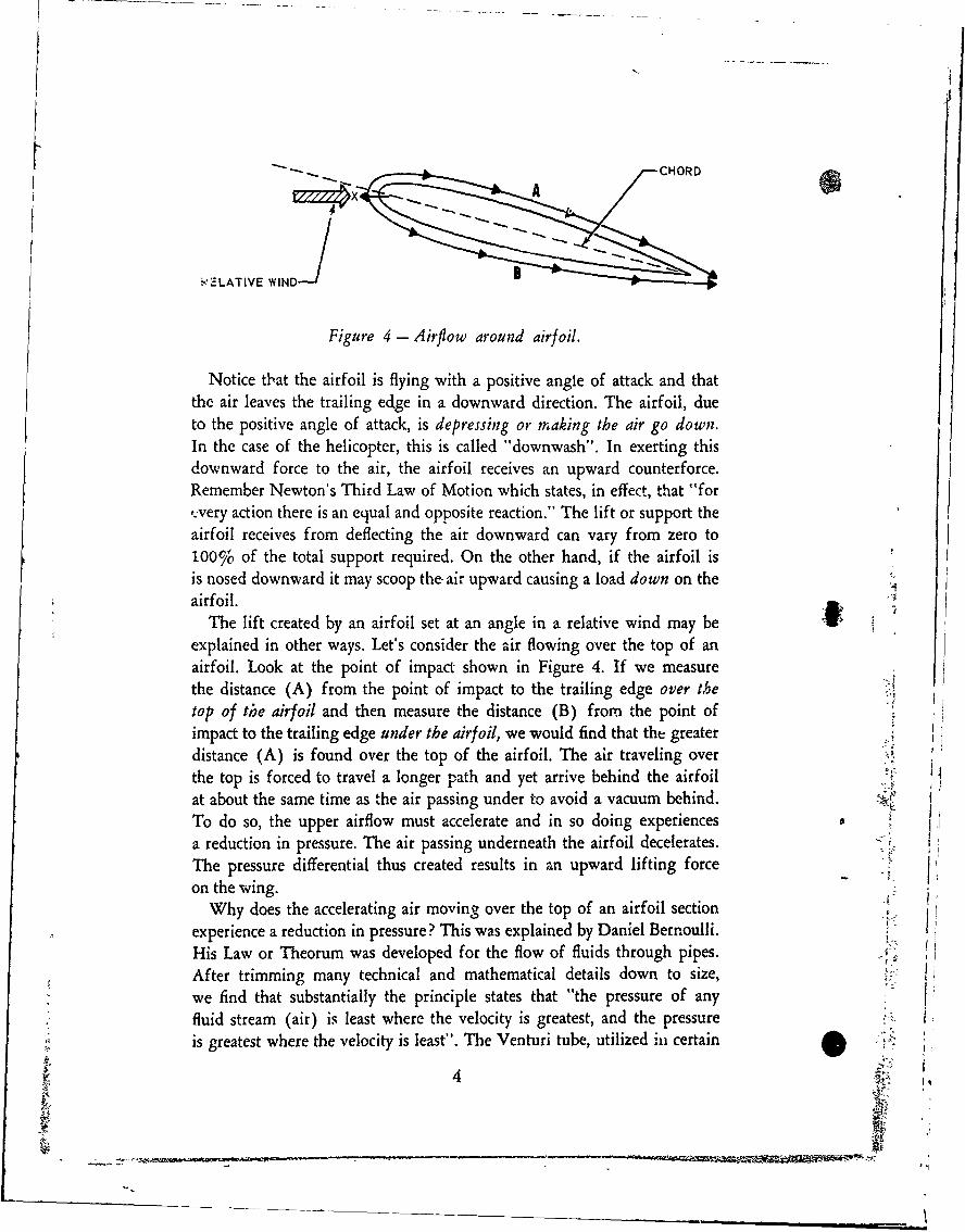
Figure 4 - Airflow around airfoil.
Notice that the airfoil is flying with a positive angle of attack and thatthe air leaves the trailing edge in a downward direction. The airfoil, dueto the positive angle of attack, is depressing or making the air go down.In the case of the helicopter, this is called "downwash". In exerting thisdownward force to the air, the airfoil receives an upward counterforce.Remember Newton's Third Law of Motion which states, in effect, that "for,.very action there is an equal and opposite reaction." The lift or support the
airfoil receives from deflecting the air downward can vary from zero to100% of the total support required. On the other hand, if the airfoil isis nosed downward it may scoop the- air upward causing a load down on theairfoil.
The lift created by an airfoil set at an angle in a relative wind may beexplained in other ways. Let's consider the air flowing over the top of anairfoil. Look at the point of impact shown in Figure 4. If we measurethe distance (A) from the point of impact to the trailing edge over thetop of the airfoil and then measure the distance (B) from the point ofimpact to the trailing edge under the airfoil, we would find that the greaterdistance (A) is found over the top of the airfoil. The air traveling overthe top is forced to travel a longer path and yet arrive behind the airfoilat about the same time as the air passing under to avoid a vacuum behind.To do so, the upper airflow must accelerate and in so doing experiencesa reduction in pressure. The air passing underneath the airfoil decelerates.The pressure differential thus created results in an upward lifting forceon the wing.
Why does the accelerating air moving over the top of an airfoil sectionexperience a reduction in pressure? This was explained by Daniel Bernoulli.His Law or Theorum was developed for the flow of fluids through pipes.After trimming many technical and mathematical details down to size,we find that substantially the principle states that "the pressure of anyfluid stream (air) is least where the velocity is greatest, and the pressureis greatest where the velocity is least". The Venturi tube, utilized hi certain
4I•2 t,q
'*
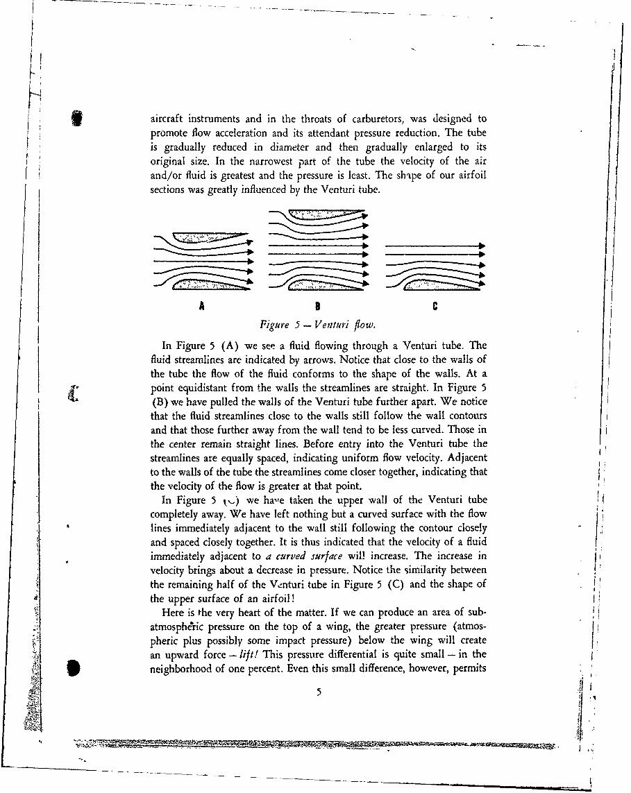
aircraft instruments and in the throats of carburetors, was designed topromote flow acceleration and its attendant pressure reduction. The tubeis gradually reduced in diameter and then gradually enlarged to itsoriginal size. In the narrowest part of the tube the velocity of the airand/or fluid is greatest and the pressure is least. The shtpe of our airfoilsections was greatly influenced by the Venturi tube.
A C
Figure 5 - Venturi flow.In Figure 5 (A) we see a fluid flowing through a Venturi tube. The
fluid streamlines are indicated by arrows. Notice that close to the walls ofthe tube the flow of the fluid conforms to the shape of the walls. At a
I• point equidistant from the walls the streamlines are straight. In Figure 5
(B) we have pulled the walls of the Venturi tube further apart. We noticethat the fluid streamlines close to the walls still follow the wall contoursand that those further away from the wall tend to be less curved. Those in
the center remain straight lines. Before entry into the Venturi tube thestreamlines are equally spaced, indicating uniform flow velocity. Adjacentto the walls of the tube the streamlines come closer together, indicating that
the velocity of the flow is greater at that point.I In Figure 5 k,.) we have taken the upper wall of the Venturi tube] completely away. We have left nothing but a curved surface with the flow
lines immediately adjacent to the wall still following the contour closelyand spaced closely together. It is thus indicated that the velocity of a fluidimmediately adjacent to a curved surface wil! increase. The increase in
velocity brings about a decrease in pressure. Notice the similarity betweenthe remaining half of the V-±nturi tube in Figure 5 (C) and the shape ofthe upper surface of an airfoil! !
Here is the very heart of the matter. If we can produce an area of sub-atmosphe'ric pressure on the top of a wing, the greater pressure (atmos-pheric plus possibly some impact pressure) below the wing will create i
an upward force - lift! This pressure differential is quite small - in theneighborhood of one percent. Even this small difference, however, permits
5
M
- - - - - - - - -

'I
adequate wing or blade loadings. Keeping in mind the fact that air hasweight, mass, density - that it weighs about two pounds per cubic yardand exerts a sea level pressure of about 14 pounds per square inch, let usassume an atmospheric pressurc of 14.70 pounds per square inch on theunder surface of a wing. Airspeed and angle of attack combinations haveproduced a pressure of 14.49 pounds per square inch on the upper surfaceof the wing. There is thus a pressure differential of 0.21 pounds per squareinch acting upward. This pressure is equal to 30.34 pounds per squarefoot - a wing loading which is quite reasonable. for certain types of air-craft.
It was stated earlier that the lift required can be acquired from thedownward deflection of the air produced by an airfoil being flown at apositive angle of attack. It is also true that the lift required can be suppliedby the reduced pressure on top of a wiag with only atmospheric pressurebelow the wing, i.e., no added impact pressure. These are two explanationsfor the creation of lift and cannot be added together. The latter case citedwould be true for a typical, general purpose wing with its flat undersurface
flying paraliel to the relative wind. At this extremely low or zero angle ofattack, or even at negative angles of attack, the low pressure on the top ofthe wing produced by its greater camber, creates the necessary pressuredifferential to supply the required lift. Naturally, as greater angles ofattack are introduced and the flat underside of the wing meets the relativewind at positive angles, the greater impact pressure causes an upward reac-tion which adds to the lifting effort.
Four major forces act upon conventional aircraft. They are lift, drag,thrust, and weight (gravity). We have spent some time discussing how liftis formed. It is, of course, the force which, in general, counteracts gravity.Drag is the force which tends to retard or resist the motion of a bodythrough the air. Thrust is the force which overcomes drag and propels the A
aircraft forward, or, as in the case of the helicopter, in any direction.Gravity (weight) is the force caused by the pull of the earth. At this timelet us have a closer look at the forces we refer to as lift and drag. Withregard to the expression "drag", we will limit our discussion for themoment to that drag which acts only upon the wing.
Lift and drag (wing) are components of the total aerodynamic forceacting upon the wing. This total force is called the resultant. Each tinyportion of the wing in flight has a small force acting upon it. The forceacting on one small portion of a wing is different in magnitude and direc-tion from all of the other small forces acting upon all of the other portionsof the wing. By considering the magnitude, direction, and location of each
4 6
1 ' '

of these tiny forces, it is possible to add them all together into one resul-tant force. This resultant force has magnitude, direction, and location withrespect to the wing. If we carry the resultant into the wing until it inter-sects the chord, the point thus derivcd is called the center of pressure. It canbe said that lift acts from the center of pressure or, stated another way,the center of pressure is the center of lift.
Later on we will discuss the movement of the center of pressure withchange in angle of attack and the implications of this movement withrespect to our choice of an airfoil for rotor blades.
The resultant force on a wing flying at a specified speed and angle ofattack might be discussed as a single entity possessing both magnitude anddirection. Such a situation is shown in Figure 6.
RESULTANT
HIGH ANGLEOF ATTACK
Figure 6 - Resultant force.
It is also possible to break the resultant down into two major compo-nents with magnitudes in two directions. In aerodynamics it is expedient
to discuss these component forces as having directions perpendicular andparallel to the relative wind. The component of the resultant force which"acts perpendicular to the relative wind is lift! The component of the
4 i resultant force which acts parallel to the relative wind is called drag!/Figure 7 shows a wing with angle of attack, relative wind, and the re-sultant with its component forces, lift and drag. Naturally, changing eitherthe angle of attack or the airspeed will cause changes in the direction,location, and magnitude of the resultant. Any change in the resultant willcause changes in the magnitude and direction of the component forces.Keep in mind that in describing lift and drag, no mention was made ofhorizontal or vertical directions. If the relative wind is horizontal, thelift is vertical and the drag is horizontal. If the relative wind is nothorizontal, then the lift is not vertical and the drag is not horizontal.
Lift is a variable force. Many factors govern the amount of lift generated
'7
I _4

L I
Figure 7- Resolution of forces.
under stated conditions. For example, as speed increases, lift increasesbecause the increased flow velocity over and under the airfoil causes alarger pressure differential. Lift does not vary in direct proportion tospeed, however. Lift varies as the square of the speed. An aircraft travelingat 100 knots has four times the lift it would have at only 50 knots.
The density of the air influences lift. Lift varies directly with density.At 18,000 feet, where the density of air is just half that at sea level, anaircraft would have to weigh only half as much, or else travel at 1.414(the square root of 2) times as fast as it would at sea level to maintainaltitude. Remember that lift varies as the square of the speed. If somefactor reduces the lift by half (the situation that exists at 18,000 feet) wehave to increase the speed so that the square of the new velocity is twicethe square of the original velocity.
From our previous discussions of how lift is produced, we have seenthat the shape of the airfoil influences lift. Generally speaking, the greaterthe camber or curvature of the airfoil, the greater the lift.
Lift also varies with the area of the wing. A wing with an area of 200square feet will lift twice as much at the same angle of attack and speed,as a wing with an area of only 100 square feet, providing proportion ofwing and airfoil section are the same.
The angle of attack greatly influences lift. The greater the angle ofattack, the greater the lift - this condition prevailing until the anglebecomes so great that the flow of air over the top of the airfoil can nolonger follow the camber smoothly, but is broken up and burbles. The wing
8
;;...... .-

* is then partially or fully stalled depending on the severity of the angle andthe aerodynamic characteristics of the airfoil.
Referring to Figure 7, the component of the resultant force which isparallel to the relative wind, drag, can be broken down into two basictypes. These are profile and induced. They are peculiar to lift or thrust-producing airfoils. Profile drag is the frictional resistance incurred whenan object is moved through a viscous fluid. Air may be considered such afluid. In simple terms, it is "sticky" and tends to cling to an object passingthrough it. This fact would indicate that the cleaner or more polished theobject is, the less profile drag incurred. Induced drag is the drag incurredin the production of lift. When an airfoil is flown at a positive angle ofattack, air is forcibly made to move in directions, at velocities, and underpressures which are not normal to its free state. Its resistance to thesechanges which are necessary to produce lift, forms the type of drag we callinduced. The remaining type of drag is termed parasite. Parasite drag isthat which is incurred by any portion of the aircraft which does not con-tribute directly to lift or thrust. Cowlings, landing gear, struts, pitot tubes,fuselage, and other accessories are examples of parasite drag producingstructures.
{ •Drag will be further discussed in the section of this text devoted topower requirements.
In our discussion thus far, we have referred repeatedly to airfoils andairfoil sections. We have mentioned a general purpose airfoil with convexupper and flat undersurface. We have talked about a symmetrical airfoil.Figure 8 shows three basic types of airfoil sections.
Each of the three basic types shown possesses certain excellent char-acteristics. Each has certain drawbacks as well. Which would be the best
GENERAL PURPOSE
HIGH SPEED
:.: ~HIGH LIFT";
S Figure 8- Airf oil types.
9I,

C= CHORD --
30%C
12% C
Figure 9- NACA 0012 airfoil.
airfoil section to use in the design of rotor blades for a helicopter?If you choose the high speed airfoil section and if you further stipulatethat it is to be the NACA 0012 airfoil which is a double convex sectionhaving equal and symmetrical curves or camber above and below the chordline, you have chosen well. In the above mentioned airfoil, illustrated inFigure 9, the NACA stands for the National Advisory Committee forAeronautics. This airfoil has its greatest thickness at 30% of the chordlength behind the leading edge. The figure -12" in the designation indi-cates that the thickness of the airfoil is 12% of the chord length at the30% chord point. The double zeros indicate a symmetrical airfoil.
Even though the symmetric .1 airfoil section does not have the greatest fcamber on its top surface as does the general purpose airfoil, it will producea pressure differential so long as it is flown at an angle of attack. Figure4 illustrates a symmetrical airfoil under lift-producing conditions.
The NACA 0012 series is widely used in the helicopter industry becausethis airfoil section affords the best lift-drag ratio for the full range ofvelocities from rotor blade root to tip. This is quite important when it isrealized that tip velocities may exceed 500 miles per hour. Keep in mindthat induced drag varies as the square of the speed. It can be seen that formaximum efficiency of the entire blade we would want an airfoil whichis efficient at the low speeds found at the root of the blade as well as thehigh speeds encountered at the tip.
From our discussions thus far, we know that as the angle of attackchanges, the distribution of the individual forces over the surfaces of theairfoil changes. This causes the resultant to act at a different location orcenter of pressure. With airfoils generally used in fixed-wing aircraft, 4changes in angle of attack result in a considerable amount of travel of thecenter of pressure. This is not a very serious problem with fixed-wingaircraft because longitudinal stability can be achieved in a number of ways.In the case of rotor blades which must change angle (feather) about afixed axis (feathering axis), the problem takes on more serious proportions.
10
___________ ___________________ _______________________3 4__4

"As shown in Figure 10, the lift-drag resultant intersects the chord line orcenter of pressure at progressively forward locations as the angle of attackis increased.
ANGLE OF ATTACK R! (LOW ANGLE OF ATTACK)
R2 (HIGHER ANGLE OF ATTACK)
R (HIGH ANGLE OF ATTACK)
FLGTRELATIVECHRDIRECTION WIND CENTER OF PRESSURE TRAVEL
Figure 10 - Center of pressure travel.
The camber itself causes a diving moment, M, which is constant, while,with respect to a rotor blade spar within the airfoil, the lines of actionthrough the aerodynamic center cause increasing stalling moments. It canbe seen that an airfoil whose center of pressure changes with angle of at-tack would not be suitable for use in a rotor blade where constantly chang-ing pitch is necessary for most directional flight speeds. Such instabilitywould cause many complications and undesirable control forces. Thesecomplications are essentially eliminated by a symmetrical airfoil sectionwhose aerodynamic center and/or center of pressure is always located onthe median line and whose feathering axis and chordwise center of gravityare located at the same point. This is illustrated in Figure 11.
CHOROWISE CENTERFEATHERING AX15 CENTER OF PRESSURE-
Figure I1 - Center of pressure of NACA 0012 airfoil.
It should b• apparent that an airfoil with many of the important factorsconcerning its performance located at one point would be relatively freeof any inherent moments which might be detrimental to its use as a rotor Vblade. In the static and aerodynamic balancing of the completed rotorblade, pitching moments are controlled and made to conform to rigid
i specifications in order to produce rotor blades which may be changed in-"A dividuady rather than in sets.
' i i 11 )
:"-2i
03_ _ _ _ _ _ _
-i *-. .--

t Chapter 2
BASIC ROTARY WING THEORYAND MAIN ROTOR CONTROL
Fortunately, there is no rule of aerodynamics which requires an airfoilto be flown in a straight line in order to perform its aerodynamic functions.The flight of a wing or a blade in a circular path around a driving shaftviolates no principle discussed up to this point. The rotating rotor bladerequires the same basic conditions to produce lift as the fixed wing flyingin a straight line. Naturally, the helicopter rotor system will be subjectedto the forces and moments peculiar to all large, rotating masses. For eachof these which might produce adverse effects on the helicopter, however,there has been a substantially successful containment. As these presentthemselves in the text, they will be fully discussed.
Figure 12 - Rotor at rest.
In Figure 12 the diagram shows a main rotor shaft with two rotor bladeslocated 180 degrees apart. The rotor is at rest and the two blades, due tothe moment caused by their span and weight, are bending downward.
Figure 13 - Rotor turning.
In Figure 13 the main rotor shaft is turning and the blades are flyinghorizontally. Blade droop has been overcome by centrifugal force. We willassume that the blades are non-twisted and that they are flying at zero Aangle of attack. Only centrifugal loadings are experienced at this time.(Aerodynamically, of course, they are also being subjected to profile dragbut we will ignore this for the time being).
In Figure 14, utilizing a shaft as an index or reference point, we have .
shown a horizontal force vector indicating centrifugal loadings. As a mat-
12

AMIL
SHAF T
Figure 14 - Centrifugal force.
ter of interest, total centrifugal loadings on each rotor blade vary, de-pending on the helicopter model, from approximately 21,000 pounds toapproximately 70,000 pounds, with rotor systems currently being designedto withstand loadings of 100,000 pounds.
I ~LIFT/L i ~(PITCH) .
SHF CENTRIFUGAL FORCE (RPM)
Figure 15 - Lift and centrifugal force.
Figure 15 shows a vertical force vector originating at the shaft or refer-ence point. To produce this vertical force, we have caused our rotor bladesto assume a positive pitch angle and, consequently, a positive angle of at-tack. The blades are no longer being acted upon solely by centrifugal force.They are also producing lift. Although one end of the rotor blade is at-tached to the shaft or hub assembly, the other end is free to respond to anyforce acting upon it. When two forces act upon one body, that body, if freeto move, will assume a position dictated by the direction and magnitude of"the two forces acting upon it. As stated, the rotor blade is attached at one
A. end, but is free to move at the other end. It will thus assume the position* tof a resultant between the two forces acting upon it. This is shown in Fig.
ure 16, with the lift force exaggerated in order to present a clear departure* "of the resultant from the horizontal.
LIFT -
(PITCH) 60AS. ~CENTRIFUGAL FORCE (RPM)
Figure 16 - Resultant of lift and centrifugal forces.
S13.4,4
Nd

It can be seen that because centrifugal loading is the predominate forceacting upon the blade, it will assume a position closer to horizontal thanto vertical. The vertical force (lift) is considerably less than the horizontalforce (centrifugal). Figure 16 is, of course, not in proper proportion inthat the lift being supplied by one blade is only about seven percent of thecentrifugal loading on the blade. Assuming a gross weight of 18,000pounds and a five blade main rotor system, each blade of the helicopter,while hovering with a load factor of one, would be producing a total of3600 pounds of lift. With a total centrifugal loading at the shaft end ofthe blade of approximately 50,000 pounds, the departure of the resultantfrom horizontal would be approximately as shown in Figure 17.
LIFT RESULTANT (BLADE)
SHAFT CENTRIFUGAL FORCE - 50,000 POUNDS
Figure 17 - Lifting rotor blade.
Having shown by the preceeding figures that a hinged rotor blade beingacted upon by two forces, one approximately horizontal and the otherapproximately vertical, will assume the position of a resultant of these twoforces, let us now return to our illustration of a main rotor shaft with twoblades 180 degrees apart, and show them responding to both centrifugaland lift forces. This is shown in Figure 18.
SHAFT4
41
Figure 18 - Lifting rotor.
With reference to Figure 18, it may be seen that the rotor blades in rota-tion fornm an inverted cone with its apex centered at the main rotor shaft.This situation gives rise to the expression "coning angle". In actual heli-
14
W_

copter operation, as pitch is increased in all blades simultaneously ind theresulting lift forces the blades to support the weight of the helicopter, avisual rotational "disk" is formed. The disk, viewed from the side as inFigure 18, is easily recognized as a cone. The dotted line connecting thetips of the blades is also visually discernable and is known as the "lippath plane".
TIP PATH PLANE
Figure 19- Hoverilig helicopter at light weight.
In Figure 19, let us assume that the helicopter is lightly loaded and ishovering. The coning angle is not large as the blades are not supportingexcessive loads nor is the helicopter climbing. The rotation of the bladesis producing a substantial amount of centrifugal loading and the combi-nation of light load, no climb, and normal RPM will maintain the coningangle at a relatively low value. I
Figure 20 - Hovering helicopter at heavy weight.
In Figure 20 let us assume that the helicopter is heavily loaded and ishovering with considerable power output. The coning angle has increasedbecause the blades are supporting more weight. Referring to Figure 17, itcan be seen that if the blade is made to support more weight, more lift willbe required. The vertical component vector (lift) will become longer(of greater magnitude) while centrifugal loading remains substantiallyconstant. The resultant of these two forces moves upward. Because theresultant corresponds to the blade, it is seen that the coning angle increaseswith greater rotor loads. Conversely, if rotor loads remain the same but
15

I
RPM is increased or decreased, the increased or decreased centrifugalloadings would also cause changes in the direction of the resultant. Itshould also be mentioned that any flight maneuver which puts a "G" loador increased "load factor" on the aircraft, will cause a higher coning angle.
By this time,-you have p.robably noticed what could be considered acontradiction between text and drawings, in that Figure 19 is said to showa rotor with a low coning angle while Figure 20 illustrates one with a highconing angle. If we were to measure the abtus e angle between the bladeswe would see that just the reverse is true, for in Figure 19 - the angle isgreater than one in Figure 20. The explanation for this apparent con-flict is quite simple. Common usage of the term "coning angle" by mainte-nance and flight personnel implies that when the blades move upwardunder load, the coning angle has increased. When the disk flattens out, theconing angle has decreased. To support common usage of the term let usdefine it as the angle formed between the blade and the tip path plane.Figures 19 and 20 are shown with this definition in mind.
From previous discussions we know that when an airfoil is passedthrough the air at a positive angle of attack and with sufficient speed, itwill produce lift. We can thus say that each blade in a rotor system suppliesits share of the required lift. Diagramatically and practically, we can saythat the total lift of the rotor may be considered to be acting from its centeror virtual axis and that the total lift of the rotor always acts perpendicularto its plane of rotation. This relationship is shown in Figure 21.
ILIFT
Figure 21 - Lifting rotor with thrust vector.
The 90 degree relationship between the total lift force and the plane ofrotation cannot change appreciably. If the plane of rotation is made totilt, the total lift force will tilt accordingly.
Up to this point, we have referred to the support force generated by therotor as lift. While such terminology is perfectly satisfactory, there is an-other way of expressing the support force in a rotor system. The rotor is, W
16
'~!i.:;
S. ...t.,,- ,-. ••- ••

after all, comparable to a large, multi-bladed propeller and we have beenused to referring to the force created by a propeller as "thrust". The factthat a helicopter rotor rotates more or less horizontally and generates aforce which is more or less vertical does not preclude our calling the force"thrust". Ac;,demically, we may call the force generated by a helicopterrotor either 'ift or thrust. For simple discussions of rotary wing flighttheory, the term "lift" is quite satisfactory. For discussions with referenceto the Fower required for various phases of rotor operation, "thrust"might be vio:c appropriate.
We are ali familiar with this basic formula:F=MA
FORCE EQUALS MASS TIMES ACCELERATIONStated simply for our purpose, it means that the desired force of a rotor,
thrust, is the product of the acceleration of a mass (air). Other thrust-producing mechanisms are covered by the same formula. An aircraft gasturbine engine achieves its thrust by giving great acceleration to reasonablequantities of air. An aircraft propeller, compared to the jet engine, pro-duces thrust by giving a lesser amount of acceleration, but to greaterquantities of air. If the propeller shaft is then rotated upward until itsplane of rotation is horizontal it becomes, in essence, similiar to a heli-copter main rotor. The helicopter main rotor produces thrust by givingeven less acceleration, but to vastly greater quantities of air.
From the discussion in the preceeding paragraph, it may be seen that ifa coter system with its plane of rotation horizontal can be supplied withsufficient power or torque, a substantial amount of air (Mass) can be givensufficient Acceleration to produce the necessary amount of thrust (Force)to lift a helicopter off the ground. As valuable as this capability is, thispurely vertical flight ability is not enough. A machine capable of onlyvertical flight would be of limited value. A directional capability is a-sorequired.
The autogyro was a partial answer to the problem. By propeller thrustit achieved a directional capability but, except for momentary abilitythrough use of the "jump" takeoff, it lacked the true vertical capability werequire. Ideally, the rotor should be capable of producing both verticaland horizontal ihrust. Let us see how this is accomplished.
In Figure 21 we see that the lift or thrust of the rotor is perpendicularto the plane of rotation. It was stated that lift or thrust always remainsperpendicular to the plane of rotation regardless of whether the rotationalplane remains level or is inclined. In other words, if the rotor were madeto tilt, the lift or thrust vector would also tilt. This is shown in Figure 22.
17

LIFT
Figure 22 - Tilting rotor -with thrust vector.
If the lift vector is broken down into components perpendicular andparallel to the ground as shown in Figure 23, there will be a generallyvertical thrust component to support the helicopter, and a generally hori-zontal thrust component producing directional flight. The helicopter willmove in the direction of rotor tilt.
TOTAL THRUST VERTICAL THRUST COMPONENT
DIRECTIONAL THRUSTCOMPON ENT
Figure 23 - Helicopter in forward flight.
For a graphic solution of how the directional thrust component His created, let us assume, as shown in Figure 24, that the total thrust createdby rotor under given power and airspeed conditions is 10,000 pounds andthat the rotor tilt is 15 degrees in the direction of flight. This means thatthe virtual axis or thrust vector of the rotor is inclined 15 degrees from 4vertical.
Let us lay off the 10,000 pounds in 2,000 pound increments on a line,AB, that is 15 degrees off vertical. Line AB represents the total thrust ofthe rotor. We will see that the vertical line, AC, representing the lift com-ponent, will scale to approximately 9700 pounds, while the horizontal ordirectional component, BC, will have a value of approximately 2400pounds.
18
S. . . .." • - • • .
- r

TOTAL THRUST
10000•• ....
LIFT APPROXIMATELY9700 POUNDS
HORIZONTAL FORCE6000 APPROXIMATELY
POUNDS 2500 POUNDS
402000
A
Figure 24 - 10,000 pound thrust at 15 degrees.
An easier and quicker method of solving the problem is by trigonome-ttry. In this solution, shown in Figure 25, the formula would be:
Lift = 10,000 (cos 15 degrees)Horizontal Force = 10,000 (sin 15 degrees)
OR
Lift = 10,000 (0.966) = 9660 PoundsHorizontal Force = 10,000 (0.259) = 2590 Pounds
"LIFT =AB (COS 150)
HORIZONTAL FORCE =AB (SIN 150)
AB 10,000 LBS
A
Figure 25 - Trigonometric solution of rotor lift.
V.19

""Reference to either the graphic or trigonometric solution of the prob-lem indicates that the greater the tilt of the rotor, the greater the hori-zontal force and, assuming that power settings and airspeed remain con-stant, the smaller the lift force.
The directional force component is, of course, opposed by the aerody-namic drag of the helicopter. As long as the horizontal force componentis greater than the drag, there will be directional acceleration. As dragincreases with increased speed, it will eventually equal the directionalforce and uniform speed will result. The same is true of the lift component.When the lift and gravity forces equal each other, the helicopter remainsat a constant altitude. A change in either of the two forces will cause eitlerclimb or descent.
With the realization that tilting the thrust vector or virtual axis of therotor introduces a directional component there were, in the early days,many novel ideas conceived to produce a rotor tilt. Undoubtedly therewere attempts to tilt the entire power package including transmission androtor head in an effort to tilt the rotor. These ideas were soon given up infavor of aerodynamic rather than mechanical tilting.
Let us analyze what had to be accomplished to produce a rotor tilt.
41 THRUST VECTORI (VIRTUAL. AXIS)
SHAFT AXIS I1
4!
Figure 26 - Rotor thrust on shaft axis.
""The dotted outline of a rotor and rotor shaft is shown in Figure 26. Therotor is turning as evidenced by a coning angle. Power is being applied.The thrust vector (virtual axis of the rotor) and the rotor shaft axis are -the same.
In Figure 27 notice that in the dotted rotor, just as it was shownin Figure 26, the thrust or virtual axis of the rotor is the same as the shaftaxis. In the tilted, solid-lined rotor, the thrust or virtual axis is not thesame as the shaft axis even though the shaft, which remains vertical, isturning the rotor. In other words, the rotor is tilted with reference to theshaft. V
20it4"
~s

THRUST OR VIRTUAL AXISOF TILTED ROTOR
THRUST OR VIRTUAL AXIS OF NON-TILTEDROTOR (SAME AS SHAFT AXIS)
A
Figure 27 - Inclined thrust.
Note also that in order to achieve a rotor tilt, the blades must pass froma low point, A, to a high point, B, 180 degrees of rotation away. In otherwords, the blades must climb from point A to point B and then dive frompoint B to point A. From our earlier discussions of aerodynamics, westated that a blade will climb or dive due to loss or gain o2" lift resultingfrom either varying airspeed or varying angle of attack. It is obvious thatwith regard to a rotor operating at a --.bstantially constant RPM, deliber-ate changing of blade a.irspeed to cause climb or dive is impossible. Whatcan be varied, however, is the angle of attack. The blades climb and divebetween points A and B causing the rotor disk to tilt, due to pitch changeswhich result in angle of attack changes.
The blade operates at a reduced pitch when moving the 180 degrees ofrotation from point B to point A. This reduced pitch causes a loss of liftwhich, in turn, causes the blade to settle or dive. The blade operates at anincreased pitch angle when moving the 180 degrees from point A to pointB. The increased pitch causes increased lift which, in turn, causes the bladeto climb. With each blade in the system following the same flight pathrotationally, the total effect is a tilted rotor with the total thrust of therotor being in the direction of the lowest point of the rotor (A).
Because this method of tilting the rotor is accomplished by changingthe pitch of each blade individually as it makes a complete rotation orcycle, the pitch change involved is called "cyclic" and the pitch control thatgoverns cyclic pitch has been named the cyclic pitch stick. The change inblade pitch is also called "feathering". Exact methods of rotor controlwill be discussed later.
21

FLAPPING ANGLE
B
ASHAFT AXIS
Figure 28 - Blade flapping.
It must be noted that when we tilt the rotor cyclically, the rotor axis(virtual axis) and the shaft axis no longer fall along the same line.
In Figure 28 the dotted lines represent the rotor with no tilt with refer-ence to the shaft. The virtual axis of the rotor and the shaft axis are on thesame line. When the rotor is tilted by cyclic pitch changes, the virtual axis(thrust vector) is inclined so as to remain perpendicular to the plane ofrotation. This means that with respect to the rotor head, the blades mustflap downward in moving from B to A and flap upward in moving fromA to B. Blade flap is thus a necessity and requires a hinge at the connectionbetween the blade and the rotor head. The angle between the shaft axisand the virtual axis of the rotor is called the "flapping angle". Note thatwe now have two angles which are peculiar to helicopter operation. Theyare the flapping angle which we just discussed, and the coning anglewhich was discussed earlier and illustrated in Figure 18.
From the preceeding paragraphs, it is quite apparent that two types of Hcontrol are necessary for the operation of the main rotor. First, we needa control to govern the amount of lift or thrust generated by the mainrotor. Second, we need a control to govern the direction of main rotorthrust.
With regard to the first requirement, it stands to reason that if we cancontrol the pitch of all the blades in the main rotor system simultane-ously, we can govern the amount of lift or thrust being generated. Be-cause this pitch increasing or decreasing action takes place on all the bladessimultaneously, it may be referred to as a collective action. The control it-self is referred to as the collective pitch control or collective pitch stick
22

The second requirement, that of controlling the direction of main rotor" F thrust, is accomplished by changing the pitch of each blade individually
as it rotates through one rotation or cycle. It is natura! to call the controlthat accomplishes this change the cyclic pitch stick.
The mechanics of such a control system call for a collective pitch stick;a cyclic pitch stick; an element where these controls can be integrated' ormixed; a non-rotating unit (stationary star) surrounding the main rotorshaft which can be raised, lowered, or tilted by action of the control sticksand a rotating unit (rotating star) attached to the non-rotating unitthrough bearings in order that its elevation and tilt will be identical witl-that of the non-rotating unit. In addition, the rotating unit muslhave pitch-control rods extending to each rotor blade in the system in
order that the unit's elevation and tilt may be manifested in pitch change!at the blades.
Figures 29, 30, and 31 illustrate the method by which both collectiv(and cyclic pitch is induced into the rotor blades. In Figure 29 notice thai
FORWARD
PITCH CONTROL ROD
ROTATING SCISSORS
ROTATING STAR
STATIONARY iI ~ ~SCISSORS i'
FORE AND AFT1: ~. CONTROL INPUT
FROM CONTROLi LEFT LATERAL STICKS VIA
CONTROL INPUT MIXING UNITFROM CONTROLSSTICKS VIA RIGHT LATERALMIXING UNIT CONTROL INPUT
FROM CONTROL•'• STICKS VIA
MIXING UNIT
TRANSMISSION STATIONARY STAR
Figure 29 - Low pitch.
23
| F
I I I rl am - .I,,• • •4•

just three (3) control rods from the control sticks (via the mixing unit)are attached to the stationary star. These input rods to the stationary star arelocated in positions as indicated in Figure 32.
The stationary star is actually a four-point star. Three of the points areconnections for the input rods, while the fourth is reserved for the sta-tionary scissors assembly. The stationary scissors assembly permits thestar to raise, lower, and tilt according to control inputs, buit will not per-mit it to rotate.
Figures 29, 30, and 31 illustrate the swash plate or azimuth star methodof transmitting control inputs to the blades. In Figure 29 the collectivepitch stick is full low and the cyclic stick is neuL al or centered. The sta-tionary star is low and level. The rotating star, being an integral thoughrotating part of the star assembly, is also low and level. Because all of theblade pitch control rods have been pulled downward by the star assembly, [all of the blades are flying at low pitch.
I tFORWARD
ROTATI NG SCISSORS
ROTATING STAR
PITCH CONTROL ROD---- RA F
F•ORE AND AFTF CONTROL INPUT* 4 FROM CONTROL
LEFT LATERAL FO OTOCONTROINPUTSTI:KS VIA
CONTROL INPUTRO MIXING UNITFROM4 CONTROL 4STICKS VIA RIGHr LATERA'.MIXING UNIT CONTPOL INPUT
FROM CONT ROLSTATIONARY SCISSORS STICKS VIA
MIXING UNIT
TRANSMISSION STATIONARY STAR
Figure 30--High pitch.
24
V I
f- .

In Figure 30 the collective pitch stick has been raised to its full highposition with the cyclic stick still neutral or centered. The star assembly,sliding upward on a ball joint on the main shaft, is now at its highest po-sition. Because all of the blade pitch control rods have been pushed up-ward by the star assembly, all of the blades are now flying at high pitch.
FORWARD
ROTATING SCISSORS
PITCH CONTROL ROD
ROTATING STAR FORE AND AFTCONTROL INPUT
LEFT LATERAL FROM CONTROL
CONTROL INPUT STICKS VIA A
FROM CONTROL MIXING UNIT
STICKS VIA RIGHT LATERAL•.•MIXING UNIT / "..• IHTLTEAN UT CONTROL INPUT
FROM CONTROL
"STATIONARY SCISSORS STICKS VIAMiX:NG UNIT
"TRANSMISSION STATIONARY STAR
Figure 31 - Cyclic pitch.
Figure 31 shows the star assembly tilted due to cyclic stick action. Thecyclic stick has been pulled AFT, pushing up on the fore and aft rod(servo). The left and right lateral rods (servos) remain stationary thusforming the pivot point for the tilting action. The lowest point of thetilted star assembly is over the stationary scissors assembly while the highestis over a position 180 degrees opposite or at the fore and aft rod (servo.)This means that the rotating star is now rotating in an inclined circle andas the blade pitch control rods rotate, they are constantly undergoing an
__ up and down motion. Because these rods are attached to the rotor blades,
25

FORWARD
LEFT LATERAL FORE AND AFT
INPUT (SERVO) INPUT (SERVO)
MAIN SHAFT
LEFT SIDE - RIGHT SIDE
SCISSORS RIGHT LATERAL
ASSEMBLY INPUT (SERVO)
AFT
Figure 32 - Rotor control input locations.
it is seen that the blades are constantly undergoing pitch change - chang-
ing from a high value to a low value once each revolution. As discussed
previously, these pitch changes cause the blades to climb and dive, thus
tilting the rotor.It should also be stated that by means of the mixer or mixing unit, both
cyclic and collective control may be utilized in any combination or mixture
desired. If cyclic stick is being applied for directional flight, the addition
of collective pitch does not (except in control systems employing lateral
lead) change the tilt of the star and/or rotor. It simply moves the star up-
ward so as to increase the pitch on all blades simultaneously thus pro-
ducing more thrust in the direction dictated by the tilt of the rotor. Lateral
lead, a control system bias, will be explained later in the text.
We have stated that by means of cyclic pitch change, we make the blades
climb from point A to point B and then dive from point B down to point
A. In so doing we effectively tilt the rotor in the direction of desired flight.
in order for the blade to pass through points A and B, as shown in Figure
33, it is obvious that they are going to have to flap up and down on a hinge.
One might be led to think that at point A where the blades are at their
lowest flapping point, they would also be at their lowest pitch. And that ac
point B where they are at their highest flapping point, they would be at
their highest pitch. If only aerodynamic considerations were involved in
the statement, it could be considered as true. A rotor system, however, has
the qualifications necessary to take on certain properties of the gyroscope.
26 I-
* * ~* +.

A
Figure 33 - Hinged rotor with flapping blades.
While we are not necessarily interested in the gyroscope's property ofrigidity in space, we are most interested in its property of precession.
Gyroscopic precession is an inherent quality of rotating bodies in whichan applied force is manifested 90 degrees in the direction of rotation fromthe point where the force is applied.
RESPONSE HERE
DOWNWARD FORCEOnAPPLIED HERE
900° UPWARD FORCE,Q 0 APPLIED HERE
RESPONSE HERE
FORWARD
Figure 34 - Gyroscopic precession.
Considering a rotating disk turning counter-clockwise as shown inFigure 34, a downward force applied to the side of the disk would causethe disk to tilt downward 90 degrees of rotation from the point where theforce was applied. Thus, to achieve a forward rotor tilt in a counter-clock-wise rotor system, the force causing the blades to flap downward over thenose must be applied to the rotor on the right side of the helicopter while Vthe force causing the blades to flap upward over the tail must be applied on
*the left side of the helicopter. 90 degrees of rotation from where the
A$ 2'27
_ _ _ _ _p.

forces were applied, the blades will flap to their highest and lowest position.The "force" referred to is, of course, pitch change. The same is true of a tiltin any direction. The cyclic pitch causing blade flap must be placed on theblades 90 degrees of rotation before the lowest and highest flap are de-sired. Precession of the rotor is taken into consideration by the controlsdesigner. His design insures that when the pilot pushes the cyclic stickforward the action will tilt the star assembly so as to place the lowest cyclicpitch on the blade over the right side of the helicopter, and the highestcyclic pitch on the blade over the left side of the helicopter. The rotor willalways tilt in the direction in which the cyclic stick is moved.
With reference to Figure 32, which shows star control input positions,the reader might wonder why the star input rods (servos) are located at45 degree angles to the longitudinal and lateral axes of the aircraft.
AFT LEFT-HAND SIDE
HORN ASSEMBLY
FORWARD
RIGHT-HAND SIDE SHAFT
PTHCONTROL ROD PITCH CONTROL RODLEADS BLADE BY ABOUT450 VIA HORN ASSEMBLY ... 1,
Figure 35- Blade pitch control linkage.
In Figure 35 it may be seen that the horn assembly forms a lever whichaffords the pitch control rod a mechanical advantage when rotating theblade about its sleeve bearirgs. If, by use of the horn assembly, the pitch
control rod is going to lead the blade by about 45 degrees, it stands to rea-son that the star input rod (servo) must be directly underneath the rod to
T control the blade's pitch at the desired point. Thus while the three starinput rods (servos) are located 90 dgerees apart, they are 45 degrees to"the longitudinal and lateral axes of the helicopter.
It should be noted that in preceeding paragraphs, each time the ex-pression "star input rod" was mentioned, the word servo was placed after
28
S. . . . .-. • •-

it in parenthesis. While it is true that these input devices may be consid-ered, as indeed they are, control rods, it is also in order to state they arehydraulically power-boosted rods or servos. In current generation heli-copters of substantial size, feedback forces from the rotor system would beimpossible to control by simple mechanical advantage in control sticks.Servos utilizing pressures of 1500 to 3000 PSI thus comprise our manda-tory "power steering".
Through our swash plate or star assembly method of rotor control, it iseasy to see how the addition of collective pitch causes greater thrust as allblades receive a pitch increase simultaneously. It might be interesting,however, to see what happens as only cyclic pitch is applied.
Before we can present a diagram showing a typical condition of cyclicpitch change, it is first required that we understand certain basic bladesettings. In the flight control rigging of a helicopter utilizing the fullyarticulated rotor head, the blades must be set at a predetermined anglewith collective pitch stick in its full low position, the star level, and cyclicpitch stick in neutral or centered.
ROTOR HEAD
PITCH CONTROL ROD(ADJUSTABLE)
BALL JOINTAND BEARING SHAFT
CONTROL INPUT ROTATING STARROD (SERVO).
STATIONARY STAR
I i
IIL-"'---" " ""',---'•TRANSMISSION
Figure 36 - Basic control and blade setting.
Figure 36 illustrates, schematically, the desired situation. We are as-suming that the collective pitch stick has been placed in its full low posi-tion, thus pulling the star assembly down the shaft to its lowest point. Thestationary star input rods (servos) have been adjusted to make the starassembly parallel with the rotor head. The cyclic stick is in neutral(centered) so that the star has no tilt. The pitch control rods are then ad-justed to place the rotor blade angle at (and this figure would vary some-what on different model helicopters) approximately 8 degrLes above a
Ii
29
K-z

plane parallel with the rotor head and star assembly. The required angleis chosen because it will produce normal autorotation RPM consideringblade twist. This particular consideration will be discussed fully later onin the text. With the above in mind, we can now have a detailed look atcyclic pitch.
FORWARD
tLOWEST FLAPPING
41 ,+.oo0+909 80 +704-6(.50o*120°I +40
+130 \ / +30+140 n 2/ 0+150 If /+10
.160// 0+170 \ PIVOT ROTATION .10
.18 N~ AXIS It 0+180 LOW POINT' -20I STAR \i0<0%. LEFT •i \ -1-30
+200o...LATERAL _., FOJJ 49HIGHEST SERVO AFT LOWESTPITCH# +21- -.l::.-... SERVO LOWEST
"".---5J~ PITCH
.2 , SCISSORS RIGHTASSEMBLY LATERAL+190--- kfI II " SERVO / 30
.180 HIGH POINT IISTAR I PIVOT • -2(
+1'I AXIS _ 10
0150 +10+140 / i +20
+130 + 30
• 100.V) 480o+70÷6°*t
HIGHEST FLAPPINGFigure 37 - Cycl:- pitch variation - full forward, low pitch. 4
In Figure 37 we are looking down on the rotor disk. We see the locationof the fore and aft, left, and right lateral servos (star input rods). We seea rotor'blade over the right side of the helicopter with its horn assemblyleading it by about 45 degrees to a point over the fore and aft servo. Inother words, the pitch change rod of the blade is directly over the fore andaft servo - the pitch change being fed back to the blade through the hornassembly.
We are now going to examine pitch change as it takes place with thecyclic stick moved to its full forward position. Remembering that for
30 !
_________

forward flight we need a low angle on the blade when it is on the rightside of the aircraft and a high angle on the blade when it is on the left sideof the aircraft because of the 90 degree force-displacement phasing, it isobvious that forward movement of the cyclic stick will pull the fore andaft servo downward thus pulling down on the blade pitch control rod androtating the blade on its sleeve bearings to a low pitch angle which is dic-tated by the limitation of stick travel. Because we moved the cyclic stickforward only, with no movement to the left or right, it may be seen thatthe star assembly is tilted low over the fore and aft servo and, pivoting onthe motionless lateral servos, high over the scissors assembly. This meansthat when the pitch control rod of any blade is over the fore and aft servo,that blade, travelling 45 degrees of rotation in back of its pitch controlrod, will be at its lowest pitch. Conversely, when the pitch control rod ofany blade is over the scissors assembly, that blade, travelling 45 degrees ofrotation in back of its pitzh control rod, will be at its highest pitch.
Utilizing the rigging figures of a current Sikorsky helicopter as an ex-ample, forward movement of the cyclic stick has placed the pitch of thereference blade over the right side of the helicopter at minus 5½2 degreesbelow a plane parallel to the rotor head and star assembly.
Let us now move the reference blade in the direction of rotation. As wemove the blade forward, its pitch control rod leaves its point over the lowpoint fore and aft servo. As the rotating star rotates toward the left lateralservo which has moved neither up nor down, it is rotating upward on aninclined plane. In so doing it pushes upward on the reference blade's pitchcontrol rod. The blade, in turn, is increasing pitch. 90 degrees of rotationlater, with the blade over the nose of the helicopter, the blade's pitch con-trol rod is over the left lateral servo and the blade pitch now reads plus8 degrees even though it has flapped to its lowest point over the nose.
As we continue to move the reference blade around to the left side ofthe helicopter, the star and the blade's pitch control rod continue to moveupward until they are directly over the scissors assembly with the blade atthe left side of the helicopter. At this point the blade pitch reads plus 211/2degrees. If you wonder how we derived the plus 211/2 degree figure, justremember that with the cyclic stick in neutral, all blade angles were plus8 degrees. Moving the cyclic stick forward made the blade on the rightside of the helicopter reduce pitch to minus 51/2 degrees - a pitch changeof 131/2 degree below the neutral reference of plus 8 degrees. It stands toreason that the blade on the left side of the helicopter would have a read-ing of plus 211/2 degrees, 131/2 degrees above the neutral reference of plus
8 degrees.
31

Moving the reference blade to a position over the tail of the helicopter
brings the star and pitch control rod of the blade over the right lateralservo. Here the blade angle reads plus 8 degrees just as it did over the nose
of the aircraft. At this point, however, it will be at its maximum upward
flapping point. Another 90 degrees of rotation brings it back over theright side of the helicopter where its angle will again read minus 5½2degrees.
With cyclic stick full forward we can determine the amount of pitch
change the blades undergo in 360 degrees of rotation by adding the lowestpitch (minus 51/2 degrees) to the highest pitch (211/2 degrees). The total
pitch change in one rotor revolution is thus 27 degrees. Because one de-
gree of cyclic pitch may be said to cause approximately one degree ofrotor tilt, we have available about 131/2 degrees of effective cyclic control
or rotor tilt in the forward direction. This amount of control is ample.FORWARDIt
HIGHEST FLAPPING
50 +60 +70 *80 +90 +100+ s° ' I I / l +110+40 n +120I
430 \ II / +130+20 \ // +140
"10 "/PIVOT ROTATION +15°
00 AXIS 1i HIGH POINT i"/ , I STAR ... \
1 0 / L E F T I S . . + 16 0
LATERAL FORE. ' FiO
-' SERVO AND AFT ..180LOWEST ,R HIGHEST
SCISSORS o .]g PITCH-r- SCISOR RIGHT = +180zASSEMBLY \ LATERAL /I~~~l -SER ! •=VO +170
0 .0 LOW POINT i\ SR164-, STAR I PIVOT 1%
+10 II AXIS +150
+20 1 i+4+23" ,/ II \ +140+40 /, L11 \ +123
+4 50 U 12+s°1 to I I | +110+67 +80 +10 +
LOWEST FLAPPING
Figure 38 - Cyclic pitch variation - full aft, low pitch.
Figure 38 shows the situation when the cyclic stick is pulled all the way
aft. Still pivoting on the two lateral servos, the fore and aft servo has nowpushed the star and blade pitch control rod upwards. Naturally the low
32

point of the star is over the scissors assembly. The angle of the referenceblade on the right side of the helicopter now reads plus 19 degrees. Just aswe did for forward stick in Figure 37, we may now trace the aft stick pro-gress of the blade through one revolution of the rotor.
Over the nose of the helicopter the reference blade will flap highest eventhough its pitch has returned to plus 8 derces. Over the left side of thehelicopter the blade angle will read minus 3 degrees because its rod is overthe scissors assembly which is the lowest point of the star. Over the tail ofthe helicopter the blade will be flapping to its lowest point even though itsangle, due to its rod being over the right lateral servo, will read plus 8 de-grees. Another 90 degrees of rotation brings it to its starting point and theoriginal angle of plus 19 degrees. Full aft stick produces a total pitchchange of 22 degrees and about 11 degrees of effective cyclic pitch controlor rotor tilt aft. This amount of aft control is ample.
Lateral control of the rotor differs from fore and aft control in thatmoving the cyclic pitch to the left or right activates the two lateral servosinstead of the fore and aft servo. As illustrated in Figure 39, the fore andaft servo and the scissors assembly now become the pivot points for thestar. The lateral servos now work simultaneously but in opposize directions.
In discussing lateral control, we now have a new starting position forthe reference blade. It is directly over the nose of the aircraft with i-s pitchcontrol rod over the left lateral servo. When we push the cyclic stick to theleft, control linkage causes the left lateral servo to move downward andthe right lateral servo to move upward. The blade, with its rod over theleft lateral servo, will experience a decrease in pitch because its pitch con-trol rod was pulled down. With full left cyclic stick the blade angle willread minus I degree.
With the reference blade rotated until it is over the left side of the heli-copter and its pitch control rod over the scissors assembly, its angle willread plus 8 degrees and it will be at its lowest flapping point. Over the tailof the helicopter the blade angle will be plus 17 degrees because its pitchcontrol rod will be over the right lateral servo-the high point of thestar. Over the right side of the helicopter the blade angle will have re-turned to plus 8 degrees, but it will be at its highest flapping point. Overthe nose of the helicopter the angle will again read minus I degree. Fullleft cyclic stick produces a total pitch change of 18 degrees which amountsto about 9 degrees of effective cyclic pitch control or rotor tilt to the left.This amount of left rotor control is ample.
Moving the cyclic control stick to the right causes the left lateral servoto move upward and the right lateral servo to move downward. The refer-
33
I A
~ _ _ _ _ _ _ _ _ _ .I

FORWARD
t
LOWEST PITCH
+10 +10+- - +20
+3° \0. 30
+4- / +40+5. ROTATION PIVOT
"LOW POINT AXIS+60,% STAR /
L TLEFT /+7, , LTER7AL
SERVG AND AFT _7LOWEST o SERVO
FLAPPNG V -:---- -_-j-+80 &HIGHESTFLAPPING+ +o- SCISSORS _ _: T FLAPPING
ASSEMBLY -, ' +9j .0o\- Il-'+0 / II HIGH POINT +10o
PIVOT L STAR %
01 AXIS I~ RIGHT + 110
+130 1 LATERA +130/ • I1 SERVO \
+140 U 2+150 " I ' +140
+16P +170 +16o+150
HIGHEST PITCH
Figure 39 - Cyclic pitch viriation - full left, low pitch.
ence blade, with its pitch control rod still over the left lateral servo, will.xperience an increase in pitch because its rod was pushed upward. With
full right cyclic stick, the angle will be plus 15 degrees. As shown in Figure40, moving the blade from the nose of the helicopter to the left side bringsits pitch control rod over the scissors assembly producing an angle read-ing of plus 8 degrees and the blade will be at its highest flapping point.Over the tail of the helicopter the blade angle will be plus 1 degree be-cause its pitch control rod will be over the right lateral servo, the lowestpoint on the star. Over the right side of the helicopter the blade angle willhave returned to plus 8 degrees, but it will be at its lowest flapping point.Over the nose of the helicopter the angle will again read plus 15 degrees.
Full right cyclic stick produces a total pitch change of !4 degrees which
34
H

FORWARD
HIGHEST PITCH
÷140 +150 +140
+130 I +130
+120 4120
+110 +1•/ROTATION PIVOT
+10 o HIGH POINT AXIS ,410P"�OTAR STAR
_, LEFT .+9+" g"o LATERAL -',_.I N-FTOR "
SERVO SERVO PLOWESTHIGHEST -. ":+: ::::APP--NG
FLAPPINGure 40 y i vi rgt l tch.
+r SSEMWBLY •f I7÷ 7°' • 11l W PINT
. 6amP af PIVOT SonToAl +6i
+5P"• LATERAL/ +5PI SERVO \
+30 I 1 + 3*+2 +!°0 2
LOWEST PITCH
Figure 40 - Cyclic pitch variation - full right, low pitch.
amounts to about 7 degrees of effective cyclic control Or rotor tilt to the
right. Ibis amount of right rotor control is ample.
Although we have discussed only fore, aft, left, and right cyclic stick
control, it should be stated that the cycitc stick is not limited to these major
directions. The stick may be moved or rotated in a circle and the tilt of the
rotor will follow it. The rotor may be tilted in any one of 360 degrees.
A nutshell summation of what we have shown in terms of blade angie
and flap may be made by stating that due to gyroscopic precession, the
force (pitch change) which causes blade flap must be applied to the blade
90 degrees of rotation preceeding the point where maximum blade flap
is desired. Once this is programmed into the flight control system, preces-
sion no longer remains a problem.
35
As

It should finally be stated that with the conditions shown it, Figures 37,38, 39 or 40, the addition of collective pitch generally does nothing tochange the rotor tilt brought about by cyclic pitch change. If five degreesof collective pitch were added, we could simply add five degrees to each ofthe angular values shown in the illustrations. The addition of collectivepitch influence, only the amount of thrust being produced by the rotor. Aspreviously mentioned, the only exception to this statement is that in heli-copters with "lateral lead" there will be a small amount of rotor tiit as-sociated with raising collective pitch due to a deliberate bias built into thesystem for the purpose of counteracting the right drift caused by thetorque compensating effect of the tail rotor. This will be fully explainedin the next chapter.
3 I
36 --'

Chapter 3S~ ARTICULATION, HINGE OFFSET
AND TORQUE COMPENSATION
It was stated in our introduction that this document is basically a dis-cussion of the flight theory, forces, phenomena, and operation of conven-tional, single rotor helicopters utilizing fully articulated rotor heads withoffset hinges. In preceeding chapters we have discussed 'u some extent,two of the three degrees of articulation found in the fully articulated rotorhead. First, the blade must be able to change pitch. It does this by rotatingits sleeve about a spindle and an associated thrust bearing assembly. Pitch,of course, is controlled by the pilot through cyclic and collective pitchsticks. Secondly, we have seen that a change in cyclic pitch causes the bladesto flap. This factor, plus the desirability of relieving bending stresses by
jt permitting the blades to cone, requires the use of flapping hinges. IThe other possibility for full articulation lies in permitting the blades
to lead and lag (hunt) in the plane of rotation. This action, of course,would require movement about a hinge with axis parallel to the main rotorshaft.
Full articulation in a rotor head permits the blades to change pitch, flap,I and hunt. Basically, pitch change is the only action controlled directly by
the pilot. The other two actions occur as a natural function of pitch changeand forces incurred during rotor operation.
In the paragraphs to come we are going to investigate each of theseblade movements with regard to the limits of action, the causes for theaction, and any special considerations relative to the action.
There is little we can add to our previous discussions of blade pitchchange. We have seen the necessity for it and we have learned how it isaccomplished.
Figure 41 illustrates a rotor blade at zero degrees flapping and showsupward flapping or coning to the extent of about 35 degrees above thezero flap line and about 5 degrees below the line. Disregarding for themoment actual rotor operation, this simply means that the blade can physi-cally flap upward more than 35 degrees without interference from any partof the rotor head assembly. The blade can also flap below the zero flap lineapproximately 5 degrees. The flapping hinge of our fully articulated rotorhead thus permits some 30 to 40 degrees of blade flap without abnormalcontact with a stop or other structure.
This flapping freedom is limited with the rotor at rest or slowly turn-ing in order that gusty wind conditions cannot flap the blades excessively
37
JL
L-L=7777ii

AA
ROTOR HEAD + 3r
I - 00 FLAPPING
SHAFT
Figure 41- Flapping limits.
and also to provide ground clearance for operating personnel or other
obstructions. Droop stops, spring and centrifugally operated, prevent the
blades from utilizing the 5 degrees of flapping below the zero flap line,
and anti-flapping restrainers, similiarly opeiated, prevent the blades from
moving upward in the plus range.
With regard to normal flight operation, the combination of blade
weight, aerodynamic loads, and centrifugal loading, permits coning angles
of about 6 degrees and flapping angles of plus or minu3 6 degrees. There
are, of course, maneuvers which could cause load factors sufficient to cone
the rotor as much as 18 degrees with flapping angles of plus or minus
12 degrees. Needless to say, these would be out of the realm of normal
flight operations. They are possible, however, without structural interfer-
ence at the rotor head.The third element of full articulation, that of movement of the blade
in the piane of rotation, is called hunting or leading and lagging. The
binge which permits this movement is commonly referred to as the drag
hinge.
SHAFT VERTICAL HINGE "
-_ _ _ - - -- -00 HUNTING
OFFSETDISTANCE + +30I
"S-
Figure 42 - Lead-lag motion limits.
Notice in Figure 42 that the blade at the zero degree hunting point
forms a pure radial line from the center of the main rotor shaft through
the axis of the drag hinge. While the blade may move approximately 3
38

* 1
degrees forward of the radial line and about 30 degrees aft of it, furthermovement is prohibited by stops on the damper. A full discussion of thedamper will be presented later in the text.
While i. is quite easy to see why the blades must be able to changepitch and how pitch changes cause coning and flapping, it is a little moredifficult to understand the reasons for permitting the blades to lead andlag. Essentially, the drag hinge is required in order that the blade mayseek a position of equilibrium aft of the radial line in powered flight andalong or slightly forward of the radial line in autorotation. If the abilityto seek various positions were not made possible by means of the draghinge, in-plane bending of the blade could occur. Such equilibrium isfound for hovering flight by equating to zero the centrifugal and aero-dynamic drag moments. The angle between the pure radial line and thespanwise axis of the blade, known as the average lag angle, is also greatlyaffected by the offset of the drag hinge from the center of the main rotorshaft. In forward or directional flight, other factors must also be con-sidered. They will be discussed later in the text.
To simplify the preceding paragraph, let us assume that a heavy, flat, thinblade is rotating at constant velocity in a chamber evacuated of air. Itwould tend to rotate maintaining a pure radial position even though adrag hinge permitted it to hunt in the plane of rotation. If air weresuddenly introduced into the chamber, the blade would experience aero-dynamic drag and would assume a position somewhat aft of the radial
-! position. Now give the blade the configuration of an airfoil and fly itwith an angle of attack. Aerodynamic drag, both of the profile and in-duced variety, will cause the blade to lag behind the radial positioneven more.
Centrifugal force would have the blade fly in a pure radial position.Aerodynamic drag and hinge offset prohibit this. Because centrifugal forceis caused by rotation or RPM, we may say that the average blade lag
angle is determined by the relative strength of centrifugal force (RPM)and drag (power). We associate drag with torque or power because itis impossible to draw large amounts of power from an engine without
loading it. The only way to substantially load a htlicopter engine is toincrease the pitch and/or angle of attack of the rotor blades. Increasingpitch automatically increases power through throttle synchronization on
a piston engine, and through the fuel control unit in a gas turbine engine.Simply stated, average lag angle is determined by RPM and power.
in Figure 43, position "A" represents the average lag angle under aI , •condition of high RPM and low power. The high RPM condition causes
Ii9
____ M 4.II

U0HUNTING
"'" • POSITION ASHAFT
VERTICAL HINGEr
SPOSITION B
Figure 43- Blade lag with power on.high centrifugal loadings which tend to bring the blade closer to theradial position. The low power condition with its associated low pitchand attendant low drag also contributes to the blade's position closer tothe radial line. In this condition, the average lag angle will be relativelysmall.
Position "'B" represents tl'e average lag angle of the blade under acondition of high power and low RPM. The lower RPM reduces centri-fugal loadings and permits the higher drag, caused by increased powerand its related increased pitch, to make the blade fly further aft of theradial position.
While it will be fully discussed later in the text, it should be men-tioned at this time that there will be a minor leading and lagging ofthe blade about the average lag angle when cyclic pitch is applied to therotor. In addition, varying air loads will also cause movement of the bladeabout the average lag angle.
In our discussions so far we have mentioned the fact that the rotorsystems we are studying utilize fully articulated rotor heads with offsethinges. The term offset covers the fact that the blades hunt and flap froma point several inches away from the center of the main rotor shaft. Be-cause early Sikorsky helicopters employed a flapping hinge which waslocated substantially at the main rotor shaft center, there are obviouslygood reasons why offset hinges were employed as the stale of the artprogressed. These will be discussed at this time.
With blades that are free to flap and hunt, and with the flapping hingelocated substantially at the center of the main rotor shaft, it may be seenthat pitching and rolling moments cannot be transmitted to the hub. Theblades will always seek equilibrium by flapping, thus eliminating the aero- Idynamic moments which might pitch or roll the aircraft. This apparentlyrosy picture had a flaw in it, however. The fact that in early helicoptersthe flapping hinge was on the shaft centerline and prohibited any mo-ments from being transmitted to the hub proved to be a problem in the[ % long run.
40
•. • - .• a .- • --• .- ....-'-" "-• • -'• • • . .. ,- ...... •'" °• • " " JR

Figure 44 - Flapping hinge without offset - neutral CG,
The simple diagram in Figure 44 indicates a rotor system wherein theflapping hinges are located on the main rotor shaft centerline. The heli-copter is hovering and the center of gravity is located substantially underthe main rotor shaft. Because in a fully articulated rotor system withoutoffset hinges, no moments can be transmitted to the hub and fuselage,tilting the rotor by cyclic pitch causes little movement of the fuselage.This is shown in Figure 45.
A B
Figure 45 - Tilting rotor without offset - neutral CG.
When cyclic stick is moved forward or aft, the resulting rotor tiltproduces thrust in the desired flight direction. The fuselage remains re-latively level during flight until large amounts of parasite drag cause aprogressively nose down condition. So long as the center of gravity re-mains within a relatively small range (about 3 inches), little difficulty isencountered.
In Figure 46, th'e center of gravity has been moved considerably aft ofits normal range. When the pilot picks the helicopter up off the groundinto a hover, the aircraft will immediately start to fly backward becausethe pilot has not applied any cyclic pitch and the rotor axis and shaftaxis are along the same line with the rotor tilted aft. The dotted linesindicate this condition. The pilot, in attempting to stop his rearwardflight, applies forward cyclic stick, thus bringing the tip path plane into a
414
_____ _____ __ f** * .- u . --

A
/j
"..-.... /.
* ..........
.,-'.--.
Figure 46 - Rotor without offset hinges - CG off center.
horizontal position. The solid lines indicate this condition. This action,of course, places the thrust of the rotor vertical and the helicopter thenhovers over one spot on the ground. In achieving this condition, how-ever, the pilot has utilized a good percentage of his forward cyclic stickrange, thus limiting himself as to the amount of speed he can produceby further forward motion of the cyclic stick.
In order to alleviate this condition of limited center of gravity travel,as well as to produce greater overall controllability and faster controlresponse, rotor heads were designed with a specified distance or offsetbetween the centerline of the main rotor shaft and the flapping hingeaxis. This distance can amount to from 6 inches to more than t 3 feet.The offset is illustrated in Figure 47.
OFFSET ,
Figure 47 - Rotor with offset hinge - untilted.
To illustrate the effects of offsetting the flapping hinge from the centerof rotation, the solid lines in Figure 48 show an offset hinged rotor headwith blades rotating. The cyclic stick has just been pushed forward. Theblades are flapping high over the tail and low over the nose, thus tilting Athe rotor forward. Notice that the virtual axis of the rotor has movedforward of the shaft axis. Remember, we are looking at the rotor at the
42
- .-. 7
_1K
V

I.,- -
4-FORWARD
Figure 48 - Til'ing rotor with offset hinges.
very instant that the cyclic stick is moved forward. (The dotted linesshow the rotor before cyclic stick movement in order to provide a refer-ence position.)
It can be seen that the mass forces of the blades (centrifugal), pullingupward over the tail and downward or straight ahead over the nose, willcause a moment at the hub or rotor head. These forces and the momentdirection are shown in Figure 48 as the shaded arrows. Due to the factthat there is considerable distance between the hinges of the blades, thecentrifugal loading of the upflapping and downflapping blades will pro-duce a moment which, acting through the offset distances, will tend toline up the plane of the rotor head with the plane of rotation.
"Figure 49 -- Rotor with offset hinge - tilted. -'
Figure 49 illustrates the situation shortly following the pushing for-ward of the cyclic stick. The moment caused by the mass forces of therotor blades has positioned the plane of the rotor head roughly parallelto the plane of rotation. Thus, the rotor head and the helicopter itself
43 An I'
A-sqn 4

have now substantially aligned themselvcs with the tip path plane of therotor. Cyclic stick has been returned to near neutral and the virtual axisof the rotor and the shaft axis are about the same.
Here we have an excellent condition for cruising flight. The rotor istilted so as to produce directional thrust for cruising, yet we have main-tained fully adequate fore and aft cyclic stick range. Under this condition,adequate amounts of controllability are available for additional forwardthrust or to handle a wide spread of center of gravity conditions.
To further contribute to this cruise condition wherein no great amountof cyclic pitch is required, the main transmission is placed into the heli-copter so that the main rotor shaft is inclined approximately 3 to 4 de-grees forward. This means that with the helicopter fuselage level, andwith no cyclic pitch applied, the rotor is already tilting 3 degrees forward.Center of gravity travel, limited to about 3 inches in the early helicopterswithout offset hinges, has been increased to more than 20 inches in cur-rent production helicopters.
Further along in this text, additional reference will be made to blademovements about the flapping and drag hinges. What we have discussedthus far will enable us to more fully understand the rotor's reaction tothese movements.
It is basic to state that a single rotor helicopter must have some meansof compensating for main rotor torque. With a main rotor rotating coun-terclockwise, main rotor torque will cause the nose of the helicopter toturn opposite the direction of rotor rotation, or to the right.
Figure 50 illustrates a main rotor turning counterclockwise. It showsthe torque force arrow pointing opposite rotor rotation. It also showsthe tail rotor with its thrust applied to the right, or in the direction ofmain rotor rotation and against the force created by main rotor torque.The helicopter is directionally stable because the torque compensatingeffect of the tail rotor has balanced main rotor torque. Naturally, mainrotor torque will vary according to the power being applied to the mainrotor. The more power, the more torque. The more torque, the morerequirement for additional thrust by the tail rotor.
Primarily the tail rotor is a torque compensating device. Secondarily,it is the means by which we control movement of the helicopter aboutits vertical axis. By over-compensating for main rotor torque (left rudder),we can turn the nose of the helicopter to the left. By under-compensatingfor main rotor torque (right rudder), we can turn the nose of the heli-copter to the right. While this method of directional cotitrol is excellent,and while the effect of main rotc torque is overcome, we pay a small 3
44

ROTATION
TORQUE
""--..->"_ TORQUECOMPE NSAT ION
. • .-- -- iTHRUST
Figure 50 - Torque compensation.
penalty for the use of the tail rotor. The penalty is the requirement forpower which must be borrowed from the total power available. Undervarying conditions and in varying amounts the transaction reduces thepower available to the main rotor. Fortunately, the power -vailable frommodern powerplants with their amazing weight-to-power ratios, toleratesthis loan of power to the tai! fotor with little serious effect on total aircraftperformance. Although there are other methods of counteracting torque,there are penalties of weight, interference, and handling qualities withoutany significant benefit in total performance.
Referring to Figure 50, it may occur to the reader that although thethrust of the tail rotor is compensating for main rotor torque, it wouldappear that another problem may have been creaced by this action. Thetail rotor, rotating in a vertical plane, is a thrust-producer. It produces
45
P,

• Ithrust by accelerating a mass of air. While the primary purpose of itsthrust is to compensate for main rotor torque, what is to prevent theentire helicopter from drifting to the right? After all, it is a propellerand it is producing thrust to the right! Actually, without correction, thehelicopter will drift to the right.
ROTAT ION
RTORQUE
SDRIFT
Z-ROTOR TILTED IN iTHiS DIRECTIONWILL. COMPENSATE
FOR RIGHT DRIFT TORQUS• COM4PENSATIONS~THRUST
Figure 51 - Lateral drift compensation.
Figure 51 illustrates a hover condition on a no-wind day. The cyclicstick is being held neutral laterally. The main rotor is not tilted to eitherleft or right and the control system does not incorporate lateral lead. . 'Because power is being applied to the main rotor, torque is present whichis being compensated for by the thrust of the tail rotor. Even though thethrust of the tail rotor is compensating for main rotor torque, that samethrust is causing the helicopter to drift to the right. This is indicated bythe large arrow.
The right drift can be eliminated by tilting the main rotor slightly tothe left. This is accomplished by applying a little left cyclic stick. Theresulting directional thrust of the main rotor to the left compensates forthe right drift. The amount of left stick necessary is barely noticeable.In some helicopters this correction is built into the control system
46

tnrough what is referred to as lateral lead. Lateral lead means that asthe coilective pitch stick is raised, thus producing more power to the mainrotor, the geometry of the control system is such that the right lateralservo moves upward a little more than the left lateral sei o. This slightbias causes the blades to flap up a little on the right side of the helicopterand flap down a little on the left side, thus producing a tilt to the left.Because the offset hinges cause the rotor head to assume a position roughlyparallel to the plane of rotation of the main rotor, the helicopter willhover slightly left wheel low. The helicopter will also hover slightly tailwheel low because the main transmission and rotor shaft have been placedinto the helicopter with a 3 to 4 degree forward tilt as discussed earlierin this chapter. With cyclic stick held in neutral longitudinally, the heli-copter will move slowly forward because of the built-in forward rotortilt. A little aft cyclic stick corrects the forward movement, but causesa slight tail low attitude in the hover.
From the above it may be seen that hovering with left wheel and tailwheel low' is normal to the single rotor helicopter incorporating offsethinges and built-in forward transmission tilt. It is interesting to note thatin the Flying Crane configuration which spends most of its time picking
up and depositing loads on the ground, the main transmission has abuilt-in tilt both forward and to the left. The resulting rotor tilt forwardand to the left produces wheels-level take off and landing attitudes withnormal loadings.
*
47 ,Sp
I •P

Chapter 4
VELOCITIES, ROTATIONAL AND OTHERWISEWITH INTRODUCTION TO BLADE TIP STALL
While the helicopter itself does not require airspeed in order to -becomeand remain airborne, its rotor blades must have sufficient air flowing overand under them to produce lift. The reqgd:ed airspeed is produced by rotat-ing the blades through the air. While this fact is elementary, some rathersurprising problems crop up during the production of the required lift.
A RELATIVEI I a •
WIND i
ROTATIO6N
II\ RELATIVE~WMI
rJt1RELATIVE I/WIND II
I 0 RELATIVEIWWIND
Figure 52 - Rotor velocity - hovering.
In Figure 52 we see a rotor d~sk with a blade extending from the centerof the main rotor shaft. The rotor is turning at 200 RPM. At the center ofthe main rotor shaft ihe rotational velocity is microscopic. At the inboardpocket of the rotor blade, the distance through space travelled by thatpocket is relatively small. Consequently its rotational velocity is not toosignificant. Remember that in the rotor hovering or rotating on a no-windday, rotational velocity means airspeed. Thus, the inboard pocket of theblade has but little airspeed. The middle pocket of the blade, however, hasa much greater distance to travel through space in one revolution of therotor. Its rotational velocity aiispeed is considerably greater. The tip of theblade must travel the entire circumference of the rotor disk in one revolu-tion. Its rotational velocity and airspeed are the maximums produced by theRPM and diameter of the rotor. Despite the 'many problems encountered by U
48

utilizing airspeed resulting from rotational velocities, one fact may benoted; the relative wind flows substantially at right angle; to the leadingedge of the blade regardless of its radial position. The relative wind cre-ated by high speed directional flight changes its perpendicularity onlyslightly. This slight change is illustrated in Figure 53.
FLIGHT DIRECTION
ROTATION
R = ROTATIONAL RELATIVE WIND! D = AIRCRAFT FLIGHT VELOCITY
RELATIVE WINDRRW= RESULTANT RELATIVE WIND
Figure 53- Relative wind perpendicularity.
In Figure 53 the blade over the nose of the helicopter has an effectiverelative wind which is the resultant of the rotational velocity relative windand the aircraft's directional velocity relative wind. Notice that the direc-tion of the resultant relative wind is not too far removed from perpendicu-larity. The same may be said for the blade passing over the tail cone or aftportion of the fuselage. It may also be seen that while the resultant relativewind may be a few degrees off perpendicularity, the actual airspeed valuewill be little affected.
With reference to rotational velocities and their associated airspeeds, it iswell to have a reference point in mind. Because the tip of the blade is sub-ject to the maximum velocities, we will utilize that location as a reference.
We have stated that the center of the main rotor shaft has negligiblerotational velocity and that the rotational velocity for each section of theblade varies according to i': radius or distance from the center of the main
49oI

rotor shaft. Let us see what sort of velocities are encountered at the tip of jthe blade.
One of our late generation helicopters has a tip velocity of 658.7 feet persecond at normal rotor RPM. In autorotation the velocity increases to 769feet per second. In terms of miles per hour this amounts to 449 miles perhour at normal RPM and 524 miles per hour in autorotation. For the sakeof a standard reference, let us utilize a reference tip speed of 500 miles perhour.
When we consider that we are asking the rotor blade to perform effi-ciently with a near-zero airspeed at the root of the blade and 500 miles perhour at the tip, we are not wrong in assuming that we will encounter a fewproblems.
This extreme airspeed differential is, of course, caused by the fact thatthe airspeed is derived from rotational velocity. The lift or thrust of theblade increases, toward the tip due to the increased rotational velocity air-speed. This increase in lift does not vary with the radius, but with theradius squared. Stated another way, lift varies as the square of the speed.
Because induced drag, like lift, varies as the square of the speed, largeamounts of induced drag will be experienced near the tips of the blades.Profile drag, varying as the cube of the speed, makes drag losses increas-ingly serious. While reduction of tip speed would alleviate this condition,this expedient is not available because the rotor has been designed to per-form in conformance with selected criteria utilizing a specified rotor diam-eter and operating at a particular RPM.
It would seem that profile drag losses and that portion of the total in-duced drag loss caus<d by non-uniformity of inflow could be reduced bytapering the blade (old method) so that the chord at the blade root isgreater than the chord at the tip. The same result could be achieved by
i, twisting the blade (current method) so that higher pitch angles exist at theroot of the blade than at the tip. Either of these methods is logical becauseprofile drag losses vary as the cube of the velocity while thrust (lift) and itsattendant induced drag vary as the square of the velocity. Quite obviouslyit is beneficial for thrust (lift) to be produced by the low airspeed part ofthe blade near the root, while keeping low angles of attack near the blade
tip. Blade twist, among other benefits, increases both the induced velocity(accelerated air) and the blade loading near the inboard section of the"blade.
The curved line in Figure 54 illustrates the lift distribution of a constantchord, untapered, untwisted rotor blade with zero airspeed at its root and"500 miles per hour at its tip. The curved lit., of course, denotes non-
50
° KI

t UNTWISTED BLADE
IDEALLY TWISTED BLADE
Figure 54 - Blade loading - twisted versus untwisted.
uniform lift distribution. The straight line in the same illustration indicatesthe lift distribution of an ideally twisted blade. It denotes uniform lift dis-tribution.
To sum up, in an untwisted blade the inflow varies almost linearly withthe radius. In an ideally twisted blade the inflow is substantially constantalong the radius. The lift of an untwisted blade varies as the radiussquared. In an ideally twisted blade the lift varies with the radius.
Physically, blade twist means just what the name implies. The blade spar,prior to the pocket attachment process and before any real surface finishingis accomplished, is placed in a fixture which holds one end of it securelyfastened. Another machine, operating on tracks, produces a torsion ortwisting of the spar at specific intervals as it moves toward the opposite endof the blade. By the time the operation is completed, the blade has beentwisted about 8 degrees negatively. This would correspond to "'washout" ona fixed wing aircraft. As an illustration of what has taken place, if the chordof the root end of the spar were held 8 degrees above horizontal, the tipof the spar would be horizontal.
Figure 55 shows how both the induced velocity and the thrust or bladeloading can be increased toward the root of the blade. While the drawingillustrates conditions implying "ideal twist" (a theoretical perfect twistdisregarding certain factors including the fact that uniform inflow distri-bution requires a different twist distribution for each thrust coefficient orclimb rate), it is nevertheless sufficient to illustrate the point.
Drawing (A) of Figure 55 shows an outboard airfoil section near the tipof the blade. The horizontal arrow indicates the direction and high velocityof rotation and the magnitude and directior, of the relative wind. The small
L451JI ,I

ANGLE OF ATTACK
ROTATION
INFLOW VELOCITY R
RESULTANT RELATIVE WIND (FLIGHT PATH) RELATIVE WIND
A(OUTBOARD)
ANGLE OF ATTACK
PITCH ANGLE
ROTATION
INFLOW VELOCITY
RESULTANT RELATIVE WIND (FLIGHT PATH) LRELATIVEWNDL
(INBOARD)
Figure 55.- Blade section angle of attack- twisted blade.
vertical arrow indicates the direction and value of the inflow wind as de-scribed in the first chapter on basic aerodynamics, Figun. 4. Naturally,when winds from two directions are acting on the blade, the actual relativewind will be the resultant of the two. The resultant relative wind is so indi-cated in the drawing. Notice that the angle of attack is much less th.a theactual pitch angle of the blade.
Drawing (B) of Figure 55 shows an inboard airfoil section near the rootof the blade. Notice that the value of the inflow has been kept constantand that the pitch of the blade varies inversely with the radius in order tomaintain a positive angle of attack.
While much of our discussion on negative blade twist pertained to hov-ering flight, its benefits also extend to forward flight in the form of better
roter efficiency. Because the rotor blade tips operate at lower ang!.3 ofattack, this area is unloadcd sufficiently to postpone the onslaught of bladetip stall. Losses due to compressibility are also reduced because reduced liftcoefficients cause the critical Mach number of the blade to increase.
52

In this chapter we have concerned ourselves only with the basic problemsof utilizing rotational velocity relative winds and airspeeds. By understand-ing these problems and correcting for those factors for which correction ispossible, we have seen that the helicopter can become airborne in the hovercondition without too much loss of efficiency.
ko"It_500 MPH
500 MPH
Figure 56 - Velocity distribution - hovering.
As may be seen in Figure 56, the establishment of the rotational airspeedvalue for any section of the blade may be computed by simple measurement.If the arrow at the tip of the blade indicates 500 miles per hour and themain rotor shaft centerline indicates zero miles per hour, the airspeed ofany radial point along the blade span can be determined by the use of aruler with appropriate increments.
As might be suspected, however, the situation changes with the introduc-tion of forward flight by the helicopter. Any object passing through the airwill create a relative wind which flows opposite the object's flight path. Thespeed with which the object passes through the air is its airspeed. In thecase of the helicopter, forward flight creates a new relative wind which hasan effect upon the one created by rotation. Rotational relative winds affectonly the rotor blades when the helicopter is hovering. The relative windcreated by forward flight of the helicopter affects not only the iotor bl?desbut the entire helicopter. Quite naturally, rotor blade airspeeds will beaffected.
53
4.!
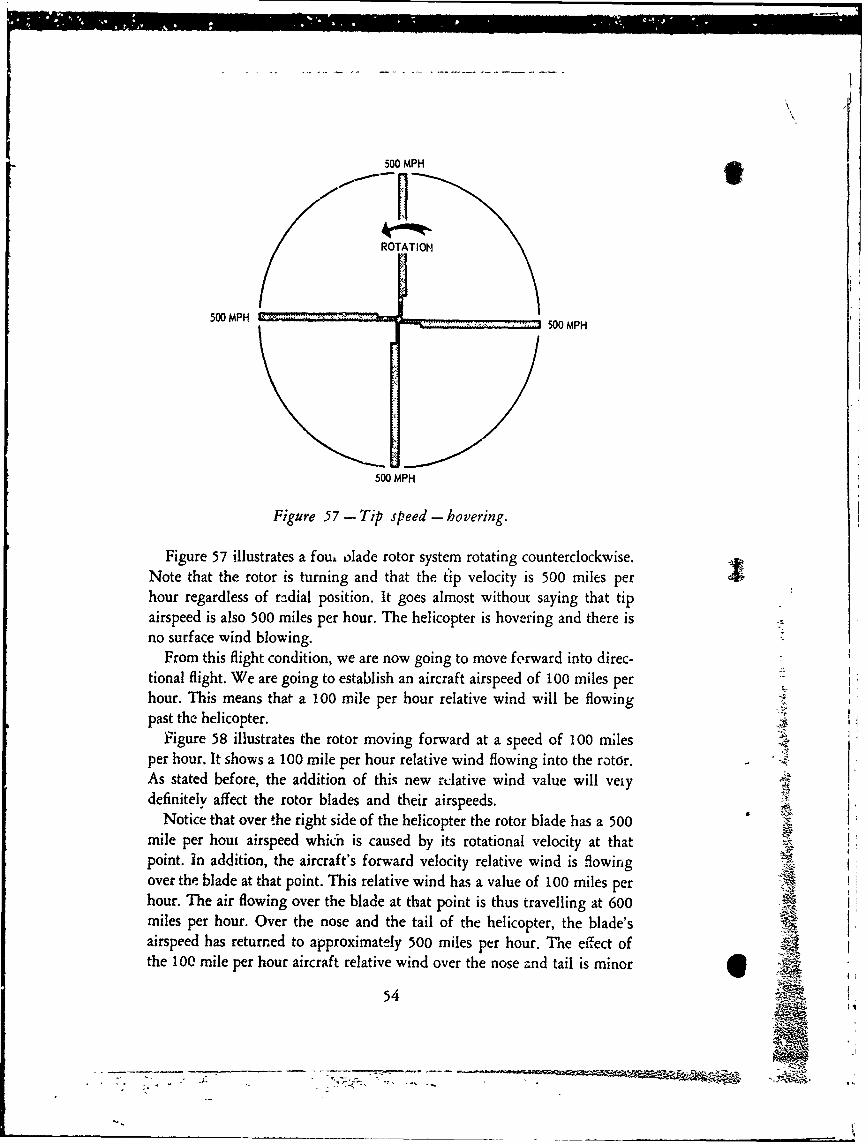
500 MPH 9
ROTATION
500 MPH 500 MPH
500 MPH
Figure 57 - Tip speed - hovering.
Figure 57 illustrates a four olade rotor system rotating counterclockwise.Note that the rotor is turning and that the tip velocity is 500 miles perhour regardless of radial position. It goes almost without saying that tipairspeed is also 500 miles per hour. The helicopter is hovering and there isno surface wind blowing.
From this flight condition, we are now going to move forward into direc-tional flight. We are going to establish an aircraft airspeed of 100 miles perhour. This means that a 100 mile per hour relative wind will be flowingpast the helicopter. K
Figure 58 illustrates the rotor moving forward at a speed of 100 milesper hour. It shows a 100 mile per hour relative wind flowing into the rotor.As stated before, the addition of this new rclative wind value will veiydefinitely affect the rotor blades and their airspeeds.
Notice that over the right side of the helicopter the rotor blade has a 500mile per houi airspeed which is caused by its rotational velocity at thatpoint. in addition, the aircraft's forward velocity relative wind is flowingover the blade at that point. This relative wind has a value of 100 miles perhour. The air flowing over the blade at that point is thus travelling at 600miles per hour. Over the nose and the tail of the helicopter, the blade'sairspeed has returned to approximately 500 miles per hour. The effect ofthe 100 mile per hour aircraft relative wind over the nose and tail is minor
54

FORWARD FLIGHTAT 100 MPH
AIRCRAFT T AIRCRAFTRELATIVE WIND RELATIVE WIND
100 MPH I 100 MPH
ROTATION
ROTATIONAL AIRSPEED 500 MPH 500 MPH ROTATIONAL AIRSPEEDAIRCRAFT AIRSPEED -100MPH +100MP AIRCRAFT AIRSPEED
TOTAL BLADE AIRSPEED 400 MPH 600MPH TOTAL BLADE AIRSPEED
Figure 58- Tip v.elocity in forward flight.
and results only in a slight change in the direction of the relative wind with-1 regard to the leading edge of the blade. This slight change was illustrated
in Figure 53.On the left side of the helicopter the rotor blade has a 500 mile per hour
rotational velocity. The 500 mile per hour airspeed that this rc)tationalvelocity would normally produce has been modified, however, by the factthat the aircraft relative wind, flowing at 100 miles per hour, is flowing inthe same direction that the blade is moving. The 100 mile per hour aircraftairspeed must therefore be subtracted from the normal 500 mile per hourrotational velocity airspeed. This leaves a total blade airspeed of only 400miles per hour over the left side of the helicopter.
It should be noted at this time that the blade travelling from the tail tothe nose around the right side of the helicopter is termed the advancingblade. It is advancing into the aircraft relative wind. The blade travellingfrom the nose to the tail around the left side of the helicopter is called theretreating blade because it is moving or retreating with the aircraft felativewind.
55

Forward flight at 100 miles per hour has thus created an airspeed differ-ential of 200 miles per hour between the tip of the blade on the right(advancing) side of the helicopter and the tip of the blade on the left(retreating) side of the helicopter. Because lift or thrust vaiies as thesquare of the velocity, the variation or dissymetry of lift between the twosides of the rotor disk becomes a serious problem.
Dissymetry of lift is not a phenomenon associated solely with the heli-copter. Practical development of the autogyro began in 1920 and the infor-mation gleaned from the process proved invaluable to those interested indesigning a successful helicopter. Any mention of the autogyro must, ofcourse, recall the name Juan de la Cierva. He flew his first autogyro in 1923and built three of them before producing a truly successful one. Discover-ing that a rotor tilted slightly back in the wind and with blades operating atlow positive angles could produce sizeable amounts of lift even at very lowspeeds, his machine's rotor turned in autorotation as the aircraft was pulledthrough the air by a conventional engine and propeller. By 1935 such fac-tors as gearing the engine to the rotor to bring it up to speed, tilting therotor axis by direct action of the pilot controls, and the jump takeoff madepossibly by overspeeding the rotor on the ground and then applying pitchrapidly, made the autogyro a close cousin of the helicopter with regard toflight characteristics.
Cierva's early autogyros utilized rigid rotors. The blades were not free toflap. It follows that as the autogyro was pulled through the air or across theground by its engine and propeller and with its rotor turning in autorota-tion, the dissymetry of lift caused by the machine's forward velocity air-speed produced a strong rolling moment. It was like trying to fly a fixedwing aircraft without aileron control and with a high angle of incidencebuilt into one wing and a negative angle of incidence built into the other.This rolling moment is illustrated in Figure 59.
ROLLING MOMENT
RETREATING BLADE ADVANCING BLADE
Figure 59 - Rigid rotor rolling moment in forward flight.
56 ;R.o18

Cierva answered the dissymetry of lift problem in bis autogyro by placingflapping hinges at the root of his rotor blades. While the flapping hingeprinciple was not new, having been put forth by a Frenchman namedRenard in 1904, Cierva refined the idea and applied it to his autogyro.
'.-fore analysis of how the flapping hinge eliminates dissymetry of lift,let us restate the problem. Dissymetry of lift is caused by the fact that inforward flight the aircraft relative wind is additive to the rotational relativewind on the advancing blade and subtractive on the retreating blade. Theblade leaving the tail and advancing around the right side of the helicopterreceives a progressively increasing amount of airspeed which reaches itsmaximum value directly over the right side of the helicopter and thenreduces to substantially normal rotational velocity airspeed over the noseof the aircraft. Leaving the nose of the aircraft, the blade experiences aprogressively decreasing amount of airspeed which reaches its lowest valueover the left side of the aircraft and then increases to normal rotationalvelocity airspeed over the tail of the aircraft. In a rigid rotor withouthinges or cyclic pitch, this dissymetry causes a rolling moment to the left.
With hinged rotor blades, the picture changes. As the blade leaves thetail and advances around the right side of the helicopter, it responds to theprogressively increasing airspeed by producing more lift and climbing(flapping) upward. In flapping (climbing) upward, however, the changein blade motion or flight path causes a change in the relative wind whichdecreases the angle of at rid thus the lift. The upward flapping veloc-ity, in order that no unt- ed forces may exist in the blade, must be ofsufficient magnitude so a decrease the angle of altack enough to keepthe lift constant. Essentially then, the extra lift and rolling moment thatwould have been produced by the additional airspeed on the advancingside of the rotor never materializes. Instead the blade attains its highestflapping position over the nose, and its lowest flapping position over thetail. A nose-up pitching moment results which can be overcome by cyclicpitch control. This will be discussed at the end of this chapter.
Figure 60 (A) illustrates a blade section with regard to flight path, angleof attack, and relative wind as it passes over both the nose and the tail ofthe helicopter (for the sake of simplicity, inflow has not been plotted). Atthese points its airspeed is substantially a derivative of rotational velocity.Figure 60 (B) shows that the increased airspeed or. the right (advancing)side of the rotor has caused the blade to flap or climb upward. Because rela-tive wind always flows opposite the flight path and because angle of attackis the angle between the relative wind and the blade chord, it is seen th-atthe angle of attack has been reduced. The reduction of angle of attack and
57

ANGLE"c- TION OF
ATTACK
-LIGHT PATH ___
(RELATIVE WIND)
ANGLE OF ATTACK AND FLIGHT PATH/RELATIVE WINDOVER NOSE AND TAIL
ARESULTANT
RELATIVE WIND
ANGLE 'OF A C
FLIGHT PATH ... ATTACK(RELATIVE WIND) - .
ROTATION +-4(a -
UPWARD FLAPPING VELOCiTY--
ANGLE OF ATTACK AND FLIGHT PATH/RELATIVE WINDOVER RIGHT (ADVANCING) SIDE
Figure 60 - Angle of attack and flight path changes - advancing blade.
its attendant cancellation of the excess lift occur as one action thus keepingthe lift constant.
As the blade leaves the nose of the helicopter and retreats around theleft side, it responds to the progressively decreasing airspeed by produc-ing less lift and diving (flapping) downward. In flapping (diving) down-ward, however, the change in flight path causes a change in the relativewind which increases the angle of attack and thus the lift. T1,e downwardflapping velocity, in order that the blade may remain in equilibrium, mustbe of sufficient magnitude so as to increase the angle of attack enough tokeep the lift constant. V
Figure 61 (A) shows the flight path, relative wind, and angle of attackof the blade as it passes over the nose and the tail. Its airspeed is sub-stantially derived from rotational velocity. Figure 61 (B) shows that thedecreased airspeed on the left (retreating) side of the rotor has causedthe blade to flap or dive downward due to the loss of lift. Rememberingthat relative wind blows opposite the flight path, it is seen that the divingflight path has caused an increase in the angle of attack. The increase ofangle of attack and its attendant build-up of the lift-loss occur as oneaction, thus keeping the lift constant.
58

ANGLE "[
ROTATION j OFATTACK
FLIGHT PATH A(RELATIVE WIND)-
ANGLE OF ATTACK AND FLIGHT PATH/RELATIVE WINDOVER NOSE AND TAIL
A
ANGLEOF
ROTATION ~ ATC
FLIGHT PATH(RELATIVE WIND) . ITY
*%'11RESULTANT RELATIVE WIND
ANGLE CF ATTACK AND FLIGHT PATH/RELATIVE WINDOVER LEFT (RETREATING) SIDE
Figure 61 - Angle of attack and flight path changes - retreating blade.
It is also true that the blades may be cyclically feathered, decreasingthe pitch on the advancing side and increasing the pitch on the retreat-ing side, in order to equalize the lift on both sides of the rotor disk.In order to produce the forward speed which causes dissymetry of liftin the first place, the cyclic stick must be moved forward in order to tilt
the rotor. Forward cyclic stick causes a lower angle on the advancingside and a higher angle on the retreating side. These angles work towardthe equalization of lift around the disk. It may be said then that bothcyclic pitch and flapping hinges work together in the elimination ofdissymetry of lift. It is interesting to remember, howeve:, that the flappinghinge is the basic weapon. After all, the autogyro had fixed-pitch bladesin most cases, and the helicopter with offset hinges and built-in shaft tiltcan, under ideal center of gravity conditions, fly with little cyclic pitch.Under these conditions, blade flapping is predomin; .'v eliminating thelift dissymetry.
The tail rotor, subject to the same problem but with no ability to cy- jlclically feather its blades, must rely solely on its flapping hinge applica-
j59
_______ ____fit
"•I

rr
AIRCRAFT RELATIVE WIND RETREATING BLADE
7% ROTATION
"ADVANCING BLADE
Figure 62- Tail rotor.
tion for equalizing the thrust dissymetry. As is shown in Figure 62, thetail rotor, even though it is rotating in a vertical plane, has an advancingand a retreating blade when the helicopter is in forward flight. Rotationalvelocity airspeeds are increased or decreased just as they are in the mainrotor and cause the sime results.
Thrust dissymetry is generally eliminated in two-bladed tail rotors byutilization of a semi-rigid seesaw rotor hub with the hin£-.! sometimesinclined from the blade feathering axis about 30 degrees. Whe- the ad-vancing blade flaps outward in response to the additional airspeed, theflapping causes a small change in the direction of the relative wind whichtends to equalize the thrust. It is aided, however, by the fact that as theblade flaps in the direction of its thrust, the 30 degree hinge mechanicallyforces a pitch change to a lower value. Naturally, the retreating blade isundergoing a pitch change to a higher value to compensate for the thrustlost by the reduced airspeed.
In four-bladed tail rotor configurations the same results are obtainedby the utilization of a delta hinge. There is no actual inclination to theblade hinge. The delta configuration is formed by the litikage betweenthe pitch control beam and the bracket or the blade sleeve, and imaginarylines drawn between each end of the pitch change link and the pitchchange axis of the blade. For a given rudder pedal setting, the pitch con-trol link holds the point at which the link attaches to the blade bracketfixed. Because this point is held firm, blade flap causes an attendant
change in blade pitch. This is difficult to portray graphically. The neuttime you are close to a non-rotating tail rotor, move a blade in its flap-ping direction and notice the pitch change taking place.
60
| 'J

t Let us now have a look at main rotor blade airspeeds during forwardflight.
FORWARD
FLIGHTAIRCRAFT AIRCRAFTRELATIVE WIND RELATIVE WIND100 MPH 100 MPH
0 MPHBLADE
AIRSPEEDHERE AIRCRAFT'
AIRSPEED TOTALROTATION 100 MPH BLADE
R OTATIONAL ARPEE.VELOCITY r 500AIRSPEED +100500 MPH -600 MPH
DOTTED LINES AND ARROWSINDICATE ROTATIONALVELOCITY
SOLID LINES AND ARROWSINDICATE ACTUAL
SREVERSE FLOW AREA BLADE SPEED
100 MPH BLADE ROTATIONALVELOCITY HERE
500 MPH ROTATIONAL VELOCITY AIRSFu.ED-100 MPH AIRCRAFT VELOCITY AIRSPEF-" (TRAVELING WITH BLADE)
400 MPH ACTUAL BLADE AIRSPEED
Figure 63 - Main rotor in forward flight.
Figure 63 illustrates a rotor in forward flight at 100 miles an hour.Blade tip rotational velocity is 500 miles an hour. Advancing blade tipairspeed is 600 miles an hour, the additive effect of rotational airspeedplus aircraft airspeed. Retreating blade tip airspeed is 400 miles an hour,theý subtractive effect of rotational airspeed minus aircraft airspeed. Theinteresting factor here is that while the main rotor shaft has no rotationalvelocity at its center, it does have airspeed. It is moving through the air Kat 100 miles an hour with the rest of the helicopter. Notice that the ar-rows which indicate total airspeed show that the main rotor shaft has I100 miles an hour airspeed and that in the area of the small circle, the iair is actually blowing over the retreating blade from trailing edge to
I 61
L __"'

V1Ii
leading edge or, to state it another way, backwards! It can further beseen that there is a point at the root of the retreating blade where theairspeed is actually zero miles per hour. At this point or radial position,the rotational velocity is 100 miles per hour. The airspeed at that pointis zero, however, because the aircraft velocity relative wind, travtlling at100 miles an hour in the same direction the blade is travelling, cancelsout the airspeed that would have been created by the rotational velocityat that point. From that point outboard, airspeed begins to pick up again,but ends up at the tip with a value of only 400 miles an hour.
It follows that with a substantially constant rotor RPM, the greater thehelicopter forward speed, the greater the advancing blade airspeed andthe lesser the retreating blade airspeed. At 200 miles an hour, the heli-copt,,r's advancing blade tip is approaching 700 miles an hour airspeed,while the retreating blade's tip airspeed has been reduced to only 300miles an hour. The critical Mach number of the advancing blade nowbecomes a problem, and the stalling out of the retreating blade tip posesan additional problem. Compressibility and blade tip stall thus presentthe ultimate challange in the nerformance of the true helicopter. Whilecritical Mach values and drag divergence are not to be overlooked, bladetip stall is probably the more important stumbling block in the way ofperformance progress. Let us have a little closer look at this phenomenon.
Its proper name is blade tip stall. It is so called because the stall beginsat the tip of the blade and works progressively inboard as the conditionswhich cause it increase in severity. It has no relationship to the obviouslystalled-out area near the center of the rotor. While we know that area 11is present, it does not manifest itself as a vibration or result in deteriorat-ing aircraft performance. Blade tip stall, on the other hand, very definitely
affects performance as well as producing vibrations, deteriorating con- Aqtrollability, and, if encouraged, an uncontrolled pitch-up.
An airfoil stalls because of the following general factors:1. Insufficient airspeed
2. Angle of attack too great3. Wing (blade) loading too great for givei, airspeed
It is interesting to consider that in a conventional aircraft, low speedperformance is limited by the stall of its witngs. In a helicopter, the re-verse is true. The helicopter's high speed potential is limifed. As the heli-copter moves forward with increasing airspeed, its retreating blade en-counters slower ind slower airspeeds. In order to continue to produceits portion of the lift required, greater angles of attack are required. It
62
,_ 4:
Al~~

jt follows that at some forward speed, the retreating blade will stall. Be-cause in forward flight the angle of attack along the span of a blade can-not be uniform, we would logically expect that some portion of the bladewill stall out before the rest. We would expect to find the stall area atthat point where the greatest angle of attack exists. Let's try to find thatpoint !
PITCH ANGLE ANGLE OF ATTACK
S.TATION 2STATION 2/ (OUTBOARD)
ANGLE OF Al TACKSTATION I(INBOARD)
ROTATION
STAI ION I INFLOW INFLOW
STATION 2 STATION 1
(OUTBOARD) (INBOARD)
Figure 64 - Angle of attack - blade root versus blade tip.
Notice in Figure 64 that the inflow through the rotor at Station 1where the rotational velocity is low (inboard) causes the angle of attack
to become smaller than the pitch angle. This, of course, is because therotational relative wind, flowing substantially horizontally, is joiled bythe inflow relative wind flowing substantially vertically, thus causing aresultant relative wind. Because angle of attack is the angle between thechord of the airf'ýii and the relative wind, it is easily seen that the newresultant relative wind causes the angle of attack to be less than thepitch angle.
At Station 2, however, our given inflow velocity is not as successful inreducing the angle of attack as it was at the inboard or root end of theblade. The increased tangential or rotational velocity at the tip affectsthe resultant relative wind so as to increase the angle of attack at thatpoint. Notice that even though the inflow velocity remains substantiallythe same, the angle of attack has increased. If the angle of attack increasestoward the tips of the blades, it caa be seen that the blade load shiftstoward the tips as conditions cause an increased inflow through the rotor.
Although we have not yet discussed power requirements in detail, itmay be stated here that the inflow through a rotor disc varies with thepower required. This will be explained in detail later in the text. For themoment, let us just state that in ho.ering, where considerable power is
63 -,

required to accelerate the air down through the rotor, the inflow is largeand the load is toward the tips of the blades. The highest angles of attackalso are located at the tips of the blades, as we saw in Figure 64. Inthe hover, however, this is not necessarily important- at least not ina consideration of blade stall.
As we move ahead with forward speed, the rotor encounters a largermass of air to which, per unit of time, it does not have to impart thevelocity that was required in the hover. The induced flow, and conse-quently the entire rotor inflow, decreases and the load moves more in-board on the blades.
At high speeds, the rotor must tilt forward in order to overcome the
high drag incurred. The relative wind czeated by the aircraft's fast direc-tional flight acts through the tilted rotor bringing about an increase ininflow and an attendant requirement for more power.
Let us repeat that the angle of attack Qistribution along the span ofa blade depends largely on the speed and direction of the rotor inflow.As inflow increases, the angle of attack at the tip of the blade increaseswith respect to the angle of attack at the root. It is not difficult to seethat as our helicopte- flies faster and faster, both the load and the angleof attack are rapidly increasing at the tip of the blade. Naturally therewill be a point at which the blade will encounter a stall condition.
A logical question at this time would be "what effect does blade twisthave upon blade tip stall?"
A blade with negative twist (lower pitch at the tip than at the root)will have a more even lift distribution along its span and will not havethe excessively high angles of attack at the tip. For normal amounts oftwist, however, the highest angles still occur at the tip of the blade! Itis true that twisted blades postpone blade stall to higher values of air-speeds. If performance is forced, however, the blade stall is inevitable.
As a helicopter approaches higher and higher velocities, we encounterthe basic factors causing stall that were listed earlier. The retreating bladeis losing airspeed. Its angle of attack at the tip is increasing. The loadingat the tip is increasing. Unfortunately, we are not able to arrive at anairspeed at which blade stall will always occur. If this were possible, the Iproblem would be simple. Instead, blade stall can occur at surprisinglylow airspeeds under one set of conditions, and still be relatively free fromblade stall at high forward speeds under another set of conditions. Whileits onslaught can be predicted, a number of factors must be considered.Among them are the following:
6 4

Airspeed
Rotor RPM
Gross WeightTemperature
Altitude
Load Factors (Gust and Maneuvering)
It could be stated in general that blade stall occurs when the rotor ih,excessively loaded. Whichever of the factors just mentioned, whetheisingly or in combination, result in high rotor loads, blade stall can resultThe nutshell rule for the elimination of blade stall once it is suspectedis unload the rotor! A little analysis and consideration of the listed factorswill show many combinations which result in high rotor loads and at-tendant blade stall.
Now that we have discussed the causes of blade stall, let us examinethe effects of blade stall upon the helicopter. Let us start by saying thatwhen the helicopter is in forward flight and blade stall is not takingplace, the rotor is in relative harmony. Dissymetry of lift is no problembecause of cyclic feathering and flapping hinges. The blades are phasedproperly except for minor blade movements caused by air loads andCoriolis effect (to be explained later in the text).
Let us depart ftom this flight condition and increase airspeed. As speedis increased we realize that the airspeed of the retreating blade is de-creasing and that in order to maintain its share of the lift, it is utilizinghigher and higher angles of attack. In addition the load is shifting towardthe tips of the blades as the inflow through the rotor increases. Eventuallywe reach a speed where the retreating blade tips experience the beginningof blade stall. In light helicopters this is indicated by a vibration felt inthe cyclic stick. As the stall condition increases in severity, the vibrationis felt in the airframe itself. We also notice that the vibration takes thefrequency of the number of blades in the rotor system as applied to one
rotation of the rotor. In other words, if the rotor system has four blades,the vibration is a four per revolution or, in the language of commonusage, a four per rev. This is explained by reference to Figure 65.
In Figure 65 we are not going to identify the angie of attack distribu-tion with any particular rotor configuration other than to state that therotor has four main blades. We will simply state that under certain condi-tions, and with preknowledge of the airfoil's stalling point and othercharacteristics, the airfoil will stall at an angle of approximately 14 de-grees. By shading in the 14 degrees contour, we can illustrate the area
65

FORWARD
t
1208
6\\ 80
// /8 .0
//10° 6
100//2
Figure 65- Angle of attack distribution.
of blade stall with regard to both radial position of the blade and thedegree of progression inboard. The solid lined rotor blades show theblades at the longitudinal and lateral axes of the aircraft, and the dottedlined rotor blades show the blades at a 45 degree angle to the major axes.
It should be noted that the tip of the retreating blade has the highestangles of attack and that from the reverse flow area outboard the angleof attack increases very rapidly. The advancing blade, on :he other hand,possesses uniform, low angles of attack. .
By observation of Figure 65 we can see that under the conditions "shown, each blade will enter the stall region on the left side of the heli-copter and will remain in that region for about a quarter of a revolution.At the beginning of the region, only the very tip is affected. Half waythrough the region the stall has progressed inboard on the blade a matterof a few feet. At the end of the region the stall is again at the very tipand from there on the blade is out of the stall area.
66

While each blade is in the stall region, it becomes out of phase withthe other blades in the system. This is caused, among other things, bythe strong drag variations experienced. Helicopter mechanics are familiarwith the one per rev vibration associated with an out of track blade. Bladestall vibrations can be thought of as such a vibration multiplied by thenumber of blades in the system. Blade stall vibrations can be thought ofas a 3, 4, 5, or 6 per rev, depending upon the number of blades utilizedin the rotor.
As blade stall begins, the pilot of the small helicopter generally notices
an increase in the general vibration level of the helicopter. He will alsonotice "kicks" in the controls. If he further increases forward speed,moves the cyclic stick forward, reduces rotor RPM, or increases the loadfactor in any other way, the stall condition will deteriorate to such anextent that the blade pitching moments become so strong that they canoverpower the servos with strong, steady vibratory loads manifestingthemselves in the control system. It is also apparent that if blade pitchingmoments are strong enough to overcome the servos, aircraft controllabilitywill become jeopardized. Serious blade stall can result in an uncontrolledpitchup of the helicopter. Naturally, blade stall should never be permittedto degenerate to this extent. If blade stall is stspected, a decrease in for-ward speed (avoiding rapid flar," educing speed), reduction of pitch,and an increase in rotor speed reduce the vibration. All of theseactions result in unloading the roto,
Blade stall experienced in straignt and level flight can generally berecognized in smaller helicopters because the vibratory forces in the con-trols provide warning of the approaching condition. In the larger, heavierhelicopters utilizing servos capable of reacting extremely heavy flightloads, instrumentation is available on some models to warn of the condi-tion.
In maneuvering flight where sharp turns and abrupt pull-ups may berequired, severe blade stall can be encountered because of rotor RPMdecay or high load factors. Recovery in these cases is much more difficult.The answer, as always, is to unload the rotor. Reduction of collectivepitch and/or increasing rotor speed will help.
Previously, we referred to a number of factors that are instrumentalin the prediction of blade stall. Among them were airspeed, altitude,rotor RPM, temperature, gross weight, and load factor. It might be inter-testing to note the extent of the effect of these factors on the retreatingblade tip speed at which stall begins.
In one of Sikorsky's venerable helicopters, no longer in production but
67A~

in extensive use in the field, it was determined that in straight and levelflight with a gross weight of 77500 pounds and a load factor of one (1),blade tip stall would occur whenever the indicated tip speed of the re-treating blade became less than 215 knots. Since the rotational tip speedof that rotor was 348 knots at 2400 engine RPM, stall theoretically wouldnot begin until a forward speed of 133 knots was atcained. This situationwas rarely met, however, because the aircraft airspeed at which blade tipstall occurred decreased about 15 knots for each 100 RPM decrease inengine speed. It decreased by about 15 knots for each 1000 pound increasein gross weight and/or load factor. It decreased by 4 or 5 knots witheach 1000 feet of altitude gain. It decreased by 4 or 5 knots with eachincrease of 0S degrees Fahrenheit.
From the above factors, it can be seen that while a chart or computorcould ')e utilized for the prediction of blade stall, the pilot could not beexpected to work changing problems in his head and come out with pin-point accuracy. He can, however, know and avoid the general conditionsconducive to the stall condition. The important thing to remember is thatblade tip stall is not solely associated with high aircraft velocities. Undercertain conditions, as outlined in the preceeding paragraph, it can occurat surprisingly low forward speeds.
With regard to the aircraft pitch-up that results from severe and ultimateblade stall, it is only necessary to remembcr that despite the fact that therotor loses lift on the left or retreating side of the helicopter, the actualsettling of the rotor will take place approximately over the tail due to thephase-displacement or, if you prefer, precession of the rotor. Rememberingthat the rotor is a centrifugally-locked rotating mass, and considering thatoffset hinges cause the fuselage to tend to line up with the plane of therotor, rotor-settle over the tail will cause the nose to rise or pitch-up. Fol-lowing the pitch-up, the aircraft will fall off to one side or the other, gener-ally to the left. As stated before, the pilot who understands blade tip stallwill never let the stall condition degenerate to this point. The mechanicwho understands blade tip stall will, together with the pilot, fully explorethe possibilities of blade stall before initiating a mechanical troubleshoot-ing routine. In the early days many a rotor head, set of blades, and damp-ers were removed from a helicopter because of a reported vibration thatlater proved to be blade stall that was not recognized by the pilot.
As mentioned previously, blade stall is not easily recognized in large,heavy helicopters that utilize strong servos to react flight loads. Severalyears ago a stall warning system was incorporated on one of Sikorsky'slarge military helicopters. It was required because blade stall was partially
68
ii,Aammme- w

blamed for several incidents where partial loss of control created uncom-fortable situations. Initially a strain gauge instrument located on the sta-
tionary star arm over the right lateral servo, it measured vibratory loadsemanating from the rotor and, through amplification and associated cir-cuitry, transmitted this information to the pilot by means of an indicatorutilizing a needle and a green, yellow, and red operating range. While thereis no need to elaborate on improvements made to the system since thattime, it nevertheless provided the pilot with adequate intelligence concern-ing the approach of blade stall. It also proved to be a valuable instrumentfor determining the loads being reacted by the flight controls. It was inval-uable for establishing and monitoring cruise control and fuel ,management.Maximum cruising speed, especially at high gross weights, is generally veryclose to the point where drag begins to increase by large increments. Theamount of power and fuel required increase very rapidly for very smallgains in speed once the rotor enters the stall condition. This drag diver-gence speed is determined by many factors. Among other things, the stallwarning, performance indicator, or cruise guide as it is now called, tells thepilot when he is cruising at speeds conducive to maximum range or whetherhe is in a partially stalled condition where he may expect excessive fuel con-sumption. Even at low gross weight conditions, the pilot may utilize theperformance indicator to increase his operating range by allowing him toreduce rotor RPM and thus benefit from additional fuel economy withoutencountering blade tip stall.
With regard to the design considerations of blade stall postponement,we have already discussed the benefits of blade twist. Additional factors to
be considered are improvements in the stall characteristics of rotor bladesections, reduction in fuselage drag which will result in a requirement forless rotor tilt at high forward speeds, and the reduction of blade loading bythe use of fixed lifting surfaces or additional propulsive devices whichunload the rotor as higher forward speeds are achieved. The future will beinteresting.
Although not directly stated as such, we have implied up to this pointthat when cyclic stick is moved out of a neutral position, the virtual axis ofthe rotor departs from the shaft axis and that in this process the plane ofthe rotor is locked to the position dictated by the amount of stick move-ment. In order to avoid confusion, the reference to any other axis has beenpostponed. In order that the reader may have a full understanding ofactual rotor position in response to cyclic stick action, we must mention thecontrol axis.{ coflThe control axis is the axis of no feathering or cyclic pitch change, or the
69

axis of constant pitch. In the hovering helicopter the control axis and thethrust vector or virtual axis of the rotor lie on the same line. A rapid appli-cation of cyclic pitch while the helicopter is hovering and before forwardspeed is built up would still show the control axis and the virtual axis onthe same line. In this latter case, of course, the shaft axis is not on thesame line.VIRTUAL AXIS SATAICONTROL AXIS VIRTUAL AXISCONTRO AXICOiN ROL AXIS
Figure 66- Rotor axes.,
Figure 66 illustrates the fact that when cyclic pitch is applied, the thrustvector (virtual axis) and the control axis depart from the shaft axis. Whilethe use of offset hinges will rapidly move the shaft axis closer to the thrustvector, we have assumed, up to this time, that there could be no separationof the control axis and the virtual or thrust axis. As defined, the controlaxis is the axis of constant pitch. Note, in Figure 66, that with respect tothe control (thrust) axis, the pitch of the blades is constant. Cyclic pitch isonly apparent when considered with respect to the shaft axis. The bladesare feathering about the shaft axis. They are NOT feathering about thecontrol (thrust) axis.
As forward flight continues and forward airspeed is attained, the actionof the blades in overcoming dissymetry of lift is going to cause a separationof the control axis and the virtual (thrust) axis of the rotor. This phenome-non is generally called "blowback" of the rotor. The separation of the con-trol and virtual axes in forward flight is shown in Figure 67.
In Figure 67 the cyclic pitch stick has been moved forward to tilt the 4
rotor. As airspeed is built up the control axis, established by the amount ofcyclic stick utilized, and the virtual (thrust) axis of the rotor begin to sepa-rate, with the virtual axis moving aft. (Shaft axis will not be further consid- Iered here because its position is determined by other considerations.) Asstated previously, this "blowback" of the rotor is caused by the action ofthe blades in eliminating dissymetry of lift.
Figures 60 and 61 show how dissymetry of lift is eliminated. It wasshown that the advancing blade, upon meeting the progressively higher air-
70

• SHAFT AXIS
S.~~,,,- VIRTUAL AXIS
,,i,•CONTROL AXIS
___ JRELATIVEWIND
FLIGHTDIRECTION
Figure 67 - Various axes in forward flight.
speeds brought about by the addition of forward flight velocity airspeed torotational airspeed, responded to the increase of speed by climbing or flap-ping upward. In so doing the change in relative wind and angle of attackreduced the amount of lift that would have been generated. In the case ofhe retreating blade, the opposite is true. As it lost airspeed, it settled or
flapped downward thus changing its relative wind and angle of attack. Theresulting larger angle of attack retained the lift that would have been lostbecause of the reduced airspeed.
Because the flapping velocity, both upward and downward, must be ofsuch a value as to increase or decrease the angle of attack so that the liftwill remain constant, it is understandable that the maximum upward flap,ping velocity will take place directly over the right side of the helicopterand the maximum downward flapping velocity will take place directly overthe left side of the helicopter. The flapping velocities are at maximumvalues directly over the right and left sides of the helicopter because atthose'locations the airspeed differential is at its maximum.
In our study of cyclic pitch and with particu!ar reference to Figure 34, wewere made to realize that in a dynamic system such as a main rotor systemwith inertia, there was a phase angle between the maximum applied force
and the maximum displacement. The force-displacement phase is 90 de-grees and it is not affected by blade mass or any kind of air damping. Itfollows then that if the maximum upward flapping velocity is directly overthe right side of the helicopter, the maximum displacement or actual flap-ping up of the blade will take place over the nose of the aircraft. Con-versely, if the maximurm downward flapping velocity is directly over the leftsid&; of the helicopter, the maximum displacement or actual flapping downof the blade will take place over the tail of the aircraft. Figure 68 showsthis relationship. The total result of this action is a rotor tilt to the rearwhich is completely independent of any additional cyclic stick action and
71

FORWARD*MAXIMUMUP-FLAPPINGHERE
MAXIMUM MAXIMUMDOWN-FLAPPING* + UP-FLAPPINGVELOCITY HERE VELOCITY HERE
MAXIMUMDOWN-FLAPPI NGHERE 4CF
Figure 68- Blade flapping resulting in blowback of rotor.
which causes an angular separation between the control axis and the virtual
(thrust) axis of the rotor.Just as in the preceding paragraphs we have described how periodic lat-
eral forces cause rotor "blowback" or separation of the control and virtualaxes of the rotor, there is yet another periodic force with a phase-displace-ment angle of 90 degrees. This one, however, arises from periodic longitu-dinal forces which result from rotor coning while the helicopter is in direc-tional flight. It causes the rotor to tilt to the side. "
From Figure 69 it may be seen that the relative wind created by thehelicopter's forward flight causes angle of attack differences between thefront and rear of the rotor. The blade over the nose of the helicopter expe-riences an increase in angle of attack because the aircraft relative windapproaches the blade level with or even below its span. The blade over therear of the helicopter experiences a reduced angle of attack because the air.craft relative wind approaches it from above.
72
• ,1

t FLIGHT
Figure 69- Airflow in forward flight.
Figure 70 shows that the higher angle of attack at the front of the rotorwill cause the blade to flap up over the left side of the helicopter and thelower angle of attack over the rear of the rotor will cause the blade to flapdown over the right side of the helicopter. The rotor will thus be tilted a
FORWARD
tLARGER ANGLEOF ATTACK HERE
ROTATION
UP-FLAPPING DOWN-FLAP PING
900 FORCE
DISPLACEMENTPHASE
P Eo'• SMALLER ANGLEOF ATTACK HERE
Figure 70 - Angle of attack variaiton causing sideward rotor tilt.
little to the right. The sideward tilt of the rotor is increased at low forwardspeeds when the induced velocities are large becausr- the inflow not onlyapproaches the rear of the rotor as shown in Figure 69, but is additionallybent downward, thus increasing the angle of attack differences.
The separation of the thrust and control axes arising from these periodiclateral and longitudinal forces is not of serious consequence in the normaloperation of the heiicoptre
73
0/
Chapter 5
POWERAND RELATED TOPICS
Whether discussing a conventional, fixed-wing aircraft or a helicopter,the energy or power required to support or propel the aircraft is dividedbetween:
(a) The Power Required to Overcome Profile Drag(b) The Power Required to Overcome Parasite Drag(c) The Power Required to Overcome Induced Drag(d) The Power Required to Produce Climb(e) The Power Required to Cause Acceleration
With reference to purely fixed-wing operation, profile and parasite powerare generally considered together. With the helicopter, however, we mustconsider them separately becaa3e of the impact of profile drag on the totalpower required. The various types of drag were defined in Chapter 1. Pro-file drag, as you -remember, is the frictional drag caused by the rotor bladesas they pass through the air. The propeller of the conventional, fixed-wingaircraft also experiences a profile drag, but not of the magnitude of thehelicopter rotor.
The power to produce climb is the amcunt over and above that requiredfor accelerated flight. Without acceleration and in level flight, we have onlythree basic power/drag factors to consider. They are induced, profile, andparasite. These will be discussed in detail together with a general powerrequired curve.
Before discussing these three factors, let us repeat that in order to keepthe helicopter airborne, the rotor must produce thrust. It does this by giv-
ing momentum or acceleration to a mass of air which, in turn, produces anupward thrust. It follows that power must be spent to produce this acceler-ation of the air mass. The amount of power spent is proportional to the i?velocity of the air beneath the rotor for a given weight of helicopt.r. Thisdownwash velocity is dependent upon the amount of air to which velocity /is given in the production of thrust. It stands to reason, then, that a rotorwith a large diameter can lift a weight with less induced power requiredthan a small diameter rotor. Additional criteria, however, must be consid-ered when determining rotor diameters. From the statements just made, wecan define thrust as equal to the mass of air moving through the rotor perunit of time, multiplied by the total increase in velocity caused by the .
action of the rotor. You'll recognize this as an application of Newton'sSecond Law of Motion, F - MA (Force Equals Mass times Acceleration)
74 -
'A,
|~

With regard to the amount of power available to the rotor and requiredto overcome the various types of drag, a general estimate for the normalhovering helicopter might be approximately 65% of .he total power for theovercoming of rotor induced drag and approximately 35% for rotor pro-file drag. It should also be remembered that the engine must, in addition totaking care of the rotor losses, supply power to turn the tail rotor andovercome friction in the transmissions and drive system. If the rotor re-ceives more power than is required to overcome profile and induced drag,the helicopter will climb.
Because forward flight is a helicopter requirement, it is interesting tonote the effect of forward speed as it pertains to the various types of dragand the power required to overcome them. Please note that the powerrequired diagrams that follow are intended to illustrate only general powertrends and no attempt has been made to furnish accurate figures or per-formance criteria.
MAX
POWER
0MA AIRSPEED 1A
Figure 71 - Profile power.
In Figure 71, the Profile Power Required Curve, it should be noted thata substantial amount of the power available is required to turn the rotorthrough the air against aerodynamic frictional forces. Since rotor speed isrelatively constant, profile drag power increases only slightly as normalforward speed is increased. At very high forward speeds and as blade stallis entered, profile drag losses mount rapidly. Once blade stall is entered,the addition of only 3 or 4 degrees of angle of attack on the blade in the
g stall region can cause an almost doubling of profile drag losses.
75
F Iq

MAX
POWER
00 MAXAIRSPEED 1
Figure 72 - Parasite power.
Figure 72 illustrates a general curve denoting the relationship betweenparasite power and airspeed. It stands to reason that at zero airspeed, therewould be no expenditure of power to overcome parasite drag. As the heli-copter picks up airspeed, however, parasite power required, varying as thecube of the airspeed, increases very rapidly at higher speeds. The moreaerodynamically clean the helicopter is, the better the picture with regardto parasite drag losses. (The same may be said for rotor blade cleanlinesswith regard to profile drag losses.)
MAX
POWERt
0 MAX
O0 AIRSPEED - WAX
Figure 73 - Induced power. -
In Figure 73 it should be noticed that at zero airspeed, the induced power _
requirement is fairly high. This is so because the rotor must imp..'t consid- V
76
-'-9

erable energy to produce the jet of air moving through the rotor. As statedpIreviously, the power required is proportional to the downwash velocityfor a given weight of helicopter. In the hovering helicopter, the downwashvelocity is near maximum value. The downwash velocity, and consequentlythe induced power required, decreases with forward speed. It reaches itslowest value in the middle ranges of speed. The reduction of induced powerrequired with forward speed is caused by the fact that as the rotor movesforward, it meets a larger mass of air per unit of time. To generate thedesired amount of thrust it does not have to impart as much velocity toeach mass of air, and the energy imparted to the air is reduced. Downwashvelocity is reduced. Unfortunately this hatpy situation cannot progress tomuch more than the middle ranges of airspeed due to rapidly rising parasitedrag losses.
400-
350-N INDUCED POWER I
300 -4,-PROFILE POWER
250- L-4 i I-fPARASITE POWER
POWER 200 -- , --
I ,I __050 "-
0 10 20 30 40 50 60 70 80 90 100 110 120
AIRSPEED -
Figure 74 - Power distribution.
The curves and values shown in Figure 74 should not be taken as per-formance criteria for any helicopter and should be viewed only as a methodof showing the trend of induced, parasite, and profile pc -.c with airspeed.In an acc,;iate illustration drawn for a particular helicopter the sum of thevalues of each of the curves at any given airspeed would give the totalpower required for level flight at that speed. An approximation of a result-ant power required curne is ofered in Figure 7-.
In Figure 75 it can be s,.en tfhat the power required to hover is quitehigh due to the high induced velocity required to produce the necessarythrust. The power required then decreases quite rapidly in the middleranges of speed as a result of decreasing induced power losses. It builds
77
V

400- I-
300
250 -- - -
POWEi- 200 -- ----- -
150o
100
50
0 10 20 30 40 50 60 70 80 90 100 110 120
AIRSPEED -
Figure 75 - Power required.
up again at the higher speeds due to the high values of fuselage orparasite drag.
If your interest is in minimum power for level flight, it can be seenthat the middle ranges of airspeed vill produce the lowest requirementfor power and fuel. It can also be stated that the best airspeed for climbwill be the one where the most power is available. This is the airspeedat which minimum power is required for level light.
The most important factor in the consideration of performance in ahelicopter is the relationship between the power available and the powerrequired. We can define the power avalikble as the rated power of theengine less the power required to operaee the tail rotor, engine and trans-mission cooling fans, and frictional losses '. the transmissioiý and otherelements of the dynamic system.
As illustrated in Figure 76, for a helicopter with adequate power, thereis ample power available to permit hovering and climbing. The diagramillustrates the relationship between power avwilable and power required. A
Good performance characteristics would be evident in this case.Because of the characteristic downward slope of the induced power re-
quired curve as airspeed is built up, it is possble to fly an overloaded or 4
underpowered helicopter :ven though vertica. P;ght or hovering is im-possible.
This situation is illustrated in Figure 77 where the weight of the heli-copter is such that more power is required to make it hover than is avail-able. Reference to the diagram shows that the power required and power
78
_ ,'7 '

1 iMAX 77'.. . .. •
POWER
PW'.-ER AVAILABLE
EXCESS POWER
POWER REQUIRED
MAXAIRSPEED
Figure 76 - Excess power.
available lines cross at approximately 20 miles per hour airspeed. If thepilot makes a ground run the helicopter will pick up airspeed. At anyairspeed over 20 miles per hour power available increasingly exceedspower required to become airborne, and excess power is developed forclimb or maneuver. The same phenomenon would be noticed if the pilotmade a vertical takeoff into a surface wind blowing in excess of 20 miles
* POWER
POWER AVAILABLE ''
EXCESS POWER" J
POWER REQUIRED 
S I I II I I I I I I
0 10 20 30 40 50 60 70 80 90 100 110
AIRSPEED -p
Figure 77 - Iniufficient power.
79

per hour. To the rotor, airspeed is airspeed whether it is derived fromforward flight in the air, from rapid taxiing on the runway, or from astrong surface wind.
This phenomenon is known as transitional or translational lift. Sub-stantially it is simply the changing relationship between power requiredand power available brought about by introducing the rotor to largermasses of air per unit of time or, in other words, giving the rotor air-speed regardless of the source of such speed.
On the first page of this chapter it was stated that power required isproportional to the downwash velocity (induced velocity) for a givenweight of helicopter. In essence this is illustrated in the description oftransitional lift. Induced power is reduced because the induced velocitydecreases with forward speed. There is yet another way for a helicopterin flight to experience a reduction in induced velocity with an attendantsaving in power. It is by means of the phenomenon known as groundcushion or ground effect.
The effect of ground cushion is not confined solely to helicopter opera-tion. Its effect is well known to pilots of fixed wing aircraft, especiallythose in the light weight category. There are times when trying to get avery light airplane back on the ground becomes rather amusing and, atother times, not so amusing -especially when the fence at the otherend of the field is getting closer and closer.
Ground effect as applied to helicopter is a most useful t.ght tool. Itenables underpowered or overloaded helicopters to hover by taking ad-vantage of the lower power required for a given thrust when operatingin close proximity (one half rotor diameter) to the ground. While groundcushion has sometimes been described as the compressing of air betweenthe rotor and the ground, it is probably best to consider the relationshipbetween induced velocity and power required. When a helicopter is hover-ing close to the ground or any structure with a fairly large, flat landingsurface, the ground or surface acts as a huge brake to the downwash.This restraint of the rotor downwash occurs as the helicopter reachesan altitude just a few feet off the ground. Because the induced velocityrequired to produce a given amount of thrust is reduced, there is a cor-responding decrease in required induced power. It follows that any de-crease in induced power results in more power being available for otheruse. It is also true that if a fixed amount of power is being transmittedto the main rotor shaft, movement onto the so-called ground cushion willproduce additional thrust.
80
-- -

While ground effect is greatly beneficial and helicopter performancecharts indicate hovering ceilings in and out of ground effect, some cautionis called for in certain types of operation, especially with marginallypowered helicopters. Operating from buildings, ships, platforms, or evencertain types of terrain under marginal conditions, can cause ground effecton half the rotor with the other half being out of ground effect or simplyirtermittant ground effect. The attendant possible settling could be trou-blesome.
No discussion of power as it applies to h,....opter operation would becomplete without mention of a phenomenon known as power settling. Athigh altitudes, high gross weights, or when operating with reduced power,it may not be possible to maintain level flight due to a lack of power.The resulting settling of the helicopter is not too important except atcertain combinations of rate of descent and low airspeed. When operatingat these combinations, the attendant power settling becomes critical.
Aerodynamic analysis of power settling shows that when a criticalpower settling condition occurs, roughness and a degeneration of controleffectiveness results. As we have seen from previous discussions, rotordownwash approaches maximum values when the helicopter is at or near
"{ the hover. Under certain power and rate of descent combinations a vortexring flow state occurs through the rotor. Vortices are built up at the tipsof the blades and in the center of the rotor. A gigantic recirculation ofair takes place in and around the rotor. The helicopter settles into theair mass its rotor has iust displaced in its attempts to produce adequatelift. The blades attempt to maintain efficiency but fall short of the desired
.goal because they are working in their own turbulence.
In extreme power settling, the velocity of the recirculoting mass becomesso high that full collective pitch and power wil! not produce sufficientthrust to slow down or control the rate of descent which can easily exceed3000 feet per minute. Recovery from this condition is made by increasingforward speed (airspeed), decreasinr -- iective pitch, or entering auto-rotation if altitude and other condi, - permit. As can easily be seenfrom the above description, considerable loss of altitude may be exper-ienced before power settling is recognized and recovery effected. Becauseof this fact, conditions tending to cause power settling should be avoidedat low altitudes.
As a last thought on this subject, under certain conditions of hig& alti-tude, high gross operation, the airspeed envelope between power settlingand blade.tip stall may be quite small.
81•_ ___,__ __ 8___ A
'.

Chapter 6
ROTOR DYNAMICS
In Chapter 3, while discussing average blade lag angles, it was pointedout that there would be a minor leading and lagging of the blade aboutthe average lag angle when cyclic pitch is applied to the rotor. It wasalso stated that varying air loads would cause some periodic in-planemovement of the blade about the drag hinge.
It is quite easy to see that because the blade is subject to varying air-.speeds and varying angles of attack during rotation, a certain amountof in-plane movement is inevitable. The movement of the blade in theplane of rotation caused by periodic mass forces is a little more complex.In mathematics these forces are called Coriolis after the mathematicianwho made a study of them. Before applying these forces to a rotor systemhowever, some discussion of the basic forces might be in order.
The law of Conserv'ation o/ Angular Momentum states that the valueof angular momentum of a rotating body will not change unless externaltorques are applied. In other words, a rotating body will continue torotate with the same rotational velocity until some extern'al force is ap-plied to change the speed of rotation. Angular momentum can be expressedas:
Mass X Angular Velocity X Radius squared
Changes in angular velocity, known as angular acceleration or decelera-lion, will take place if the mass of a rotating body is moved closer toor further from the axis of rotation. Acceleration will take place if themass is moved closer to the axis of rotation and deceleration will takeplace if the mass is moved further away from the axis of rotation. Thespeed of the rotating mass will increase or decrease in proportion to thesquare of the radius.
Most of us have seen an excellent example of this principle when.watching a figure skater on. ice skates. The skater begins a rotation onone foot, with the other leg and both arms extended. The rotation ofthe skater's body is relatively slow. When the skater draws both armsand the other leg inward, his body is suddenly rotating almost faster thanthe eye can follow. When he pulled his arms and leg in, his moment ofinertia (Mass times Radius Squared) became much smaller. Because hisangular momentum must, by law of nature, remain the same (no externalforce was 'applied), his angular velocity had to increase.
82

The mathematician, Coriolis, was concerned with the forces generatedby such radial movements of mass on a rotating disk or plane. Theseforces, which cause acceleration and deceleration, bear his name.
TANGENTIAL RADIALVELOCITY VELOCITY
i,1
0
Figure 78 - Rotating masses.
In Figure 78 a mass is being moved radially outward at constant velocityon a rotating disk. As its radius is increased, the mass is experiencing aprogressive increase in its tangential velocity. According to Newton'sLaw, any mass will resist a change in velocity. The outward moving massin Figure 78 resists the tangential acceleration to the left by exerting aforce to the right on its surroundings. If it were moving radially inwardon the rotating plane, the opposite would be true. Considering this resist-ing force in terms of rotation, it may be stated that:
FA mass moving radially outward on a rotating disk willexert a force on its surroundings opposite to rotation!
A mass moving radially inward on a rotating disk willexert a force on its surroundings in the direction ofrotation.
Now let us apply this concept to a rotor system. First of all, what isthere in the rotor system that has mass? Obviously the major rotating
83
A',•

elements in the system are the rotor blades. A center of mass can cer-tainly be established for the rotor blade.
SHAFT AXIS •
VIRTUAL AXIS
MASS _, ,RMASS
Figure 79- Blade mass on coned rotor -with no tilt.
In Figure 79 we see a diagram of a rotor viewed from the side. It isrotating. The shaft axis and the virtual axis of the rotor are the same.The blade center of mass has been located. No Coriolis force is presentbecause the radius of the mass is constant. It is neither moving towardnor away from the center of rotation. As the rotor is turning at constantrotational speed, the speed of the blade mass is proportional to its radius.
SHAFT AXIS-ýý. VIRTUAL AXIS
MASS IMASSI
FWD
CHHANGIN RADIUS CHANGE
IN RADIUS
Fgure 80- Blade mass movement on cyclically tilted rotor.
The dotted rotor outline in Figure 80 duplicates the situation shownin Figure 79, with no blade flap and the blade mass rotating at constantradius, R1. The solid lined rotor has cyclic pitch applied. It is tilted withrespect to the main rotor shaft. The shaft axis and the virtual axis ofthe rotor no longer fall upon the same line. The forward blade is flappingdown and the rearward blade is flapping up. Notice that the mass of the '.4if
84
iOwn

low -flapping blade has moved further away from the axis of rotationS~(Radius R,2) while the mass of the high flapping blade has moved intoward the axis of rotation (Radius R3). Whenever the shaft axis and the
virtual axis of the rotor are not the same (when cyclic pitch is beingapplied), the radius of the blade mass will not be constant and it willhave a periodic velocity toward or away from the center of rotation.
We have stated before that any rotating mass which also has a velocitytoward the center of rotation generates a Coriolis force in the directionof rotation. When the velocity is away from the center of rotation, theCoriolis force is opposite rotation. The first is an accelerating force, thesecond a decelerating force.
The total force on the blade is the sum of the forces on the individualelements. In the cyclically tilted rotor Coriolis forces cause the bladesto hunt forward or backward (lead and lag) (accelerate or decelerate)just enough so that the forces stay in balance and angular momentum isconserved. This produces a hunting motion of the blades of about 1 to 2degrees forward and aft of their mean lag angle.
$D
SHAFT AXIS AND VIRTUAL I !AXIS ARE THE SAME
Figure 81 - Coned rotor references.
In Figure 81 we see a side view of a rotor with coning. We also seeSthe rotor view ed directly irom above. N o cyclic pitch is applied. The
1} 85
1] '
*1°

virtual axis of the rotor and the mechanical shaft axis are the same. Inobeyance to the law of conservation of angular momentum, the tips ofthe blades have constant angular velocity and are passing from A'to Bto C to D in the same units of time.
SHAFT AND LAGVIRTUAL AXIS D-----VIRTUAL AXIS OFOF DOTTED -TO
UNTILTED ROTOR TILTED ROTORSHAFT AXIS OFi .TILTED ROTOR /
II
A/ A
SLEAD• I ROTATION /i ]
TILTEDROTORFigure 82 -Reference changes on cyclically tilted rotor.
In Figure 82 the dotted rotor illustrates the same rotor shown inFigure 81. Shaft and virtual axes are the same. There is no cyclic pitch,no rotor tilt. The Lips of the blades are passing from points A' to B toC to D in the same units of time.
In Figure 82 the solid lined rotor has cyclic pitch applied. The rotoris tilted with respect to the shaft. The shaft axis and the virtual axisare not the same. T he center of the rotor or virtual axis has moved for-ward and the blades are passing from points A' to B' to C' to D' in thesame units of time in order that angular momentum may be preserved.Note however, that when the rotor was tilted forward, the shaft axisdid -not tilt with it! The blades, which are attached to the hub, are rotat-ing about: the shaft axis but the tips of the blades must pass from A' to
4o 86
Z, ý_/ft.,,• /A/

B' to C' to D' in the same units of time. In order for the blade, whichis attached to the mechanical shaft axis, to get past point B to point B',it must lead. Swinging around the left side of the helicopter the bladedoes not have to go all the way to D, it need only get to point D'. As aresult, it lags. The terms leading and lagging are synonymous with ac-celeration and deceleration. By coupling the mathematical analysis of theperiodic changes of mass radius and its resultant acceleration and decelera-tion forces with the visual presentation shown in Figure 82, we can seethat while the tips of the blades maintain angular momentum, the re-maining portions of the blades do the actual leading and lagging, theacceleration and deceleration. If the last sentence is not clear, just remem-ber that the tips of the blades, due to unchanging angular momentum,are passing through points A', B', C', D, in exactly the same unit oftime and those points are 90 degrees apart! If it were possible for youto stand on an extension of the shaft axis and look down on the tCtedrotor, you would see the blades periodically moving back and forth inthe plane of rotation - in other words, leading and lagging. If you couldstand on an extension of the virtual axis of the tilted rotor, you wouldsee the blades rotating, evenly spaced and phased, with no leading andlagging.
D) D't!
BENDING BLADE
Figure 83 - Lead-lag bending of rigid rotor.
In Figure 83 we will assume that the blades in the rotor have no draghinges about which they can hunt. They are rigid in the plane of rotation.Notice that as the rotor is tilted with respect tc the shaft, the tips of the
87

blades pass through points A', B', C', and D' in the same unit of time eventhough the roots of the blades are attached to the hub which did not moveforward with the virtual axis of the rotor. In order for the bladis to passthrough the prime (') points, the blades must bend as indicated by thecurved blades in the diagirm. These in-plane bending moments in the bladewould be transmitted to the main rotor shaft and would cause vibrations inthe entire helicopter if they were not relieved. Blade life would be greatlyreduced by these oscillating shear loads. These forces are relieved by theaddition of drag hinges which permit the blade to hunt in the plane ofrotation according to the periodic air load and mass forces involved.
From our discussion of Coriolis forces, we can see additional reasons forthe use of the fully articulated rotor head with offset hinges. It is unfortu-nate, however, that in the solving of one problem, we sometimes createanother. ThT addition of drag hinges substantially relieved 0'-- in-planebending moments caused by periodic air loads and mass forces, but in giv-ing the blade freedom of movement in the plane of rotation, the door wasleft open to another problem, namely, ground resonance.
Of the two types of vibrations found in helicopters, ordinary and self-excited, ground resonance is of the self-excited type. Self-excited vibrationsneed no periodic external forces to start or maintain them. When a couplingor interaction occurs between the movement of the rotor blades about their ,drag hinges and a frce-and-aft or sideward movement of the main rotorshaft (i.e., the whole aircraft), the result is a self-excited vibration. Duringresonance, the helicopter rocks fore-and-aft or sideways with increasingmagnitude, with the rotor blades weaving back and forth in the plane ofrotation and out of pattern. The phenomenon is known as ground reso-nance because the vibration occurs when the aircraft is on the ground sup-ported by its relatively soft tires and oleo struts, a support conducive to alow frequency movement of the aircraft either fore-and-aft or sideways.This instability, created by the interaction of a helicopter's rocking on itstires and the oscillation of the blades about the drag hinges, can cause Idestruction of the aircraft. During ground resonance, the blades are defi-nitely out of pattern. If one blade leads while an adjacent blade lags, theresultant out-of-balance condition of the rotor causes the shaft axis to fol-low the heavy or more centrifugally loaded section of the rotor. Becauseboth the rocking and the movement of the blades in and out of patternexcite each other to greater magnitudes, ground resonance forms an excel-lent example of negative 'stability or negative damping. Figure 84 illus-trates how blades out of pattern can bias the centrifugal balance of therotor syst.m. The shaded portion of the rotor is the heavy side. Following t
88
____ ____ ____ ____ ___ ____ ____I ,

Figure 84- Blade motion in ground resonance.
the heavy side of the rotor, the shaft will describe a circle or eccentric whichwill cause the aircraft to rock.
To reiterate, two conditions must exist to cause ground resonance. First,there must be some abnormal lead/lag condition which dynamically unbal-ances the rotor. This could be caused by a blide badly out of track, a faultydamper, or a peculiar set of landing sequence conditions. Secondly, a reac-tion between the aircraft and the ground via tires or struts which wouldaggrevate and further unbalance the rotc-.. When, during the course of alanding, a wheel reaction occurs that would ciuse a set of blades alreadyout of pattern to become even further out cf phase, and this out-of-phasecondition progresses to the point of maximum lead and lag blade displace-ment, ground resonance will undoubtedly accur. A hard, one-wheel land-ing with a tricycle landing gear would be an example of such a situation.
Many pilots will remember instances when a helicopter went into groundresonance when it was in the process of slowly lifting off the ground or was ppartially airborne. This was particularly true when the helicopter landing 4gear utilized air-oil struts (oleo). The rate of the air spring in the strutvaries with its deflection thus causing the helicopter's natural frequency tovary according to the amount of weight on the gear. A helicopter might bequite stable when all its weight is on the ground, but might experienceinstability when partially airborne.
When resonance is suspected and rotor RPM is within operating range,the immediate application of power and a rapid takeoff will stop the condi-tion. By becoming fully airborne the helicopter's natural frequency changes.
89S1A .
VI

As rolling and lateral natural frequencies attenuate, the interaction or cou-pling between the blades and the airframe is destroyed and the conditionceases.
Adequate system damping and control -A the helicopter's natural fre-quencies have, to all extents and purposes, practically elim: .,ted groundresonance as an operating problem. Engineers accomplished this by refine-ments resulting from intimate studies of blade dampers, oleo struts, springrates, tire/spring rates, and landing gear types and treads.
It is apparent that drag hinges arc mandatory. It is also apparent thatthe drag hinges permit the movement of the blade in the plane of rotationwhich, when the aircraft is on the ground, can result in resonance whencoupled with other factors. In flight, we desire that the blades have substan-tial freedom of movement in the plane of rotation. On the ground wewould like to have the blades fixed in the plane of rotation. Obviously somesort of a compromise is called for. Let us now introduce the damper.
Figure 85 -Rotor with blade dampers.
The damper is a unit consisting o.' a cylinder, piston, and piston shaft.
The cylinder or housing, as sh..wn in Figure 85, is attached to the rotorhead aft of the blade it is serving. The forward end of the piston shaft isattached to the drag hinge (i.e. the blade). The movement of the blade isrestrained because hydraulic fluid must flow from one side of the piston tothe other through a restricted orifice. o
The action of the restricted orifice inhibits the in-plane movement of theblade sufficiently to keep the blades in phase during ground operation.
"90
F I Adequate freedom of in-plane movement of the blades in flight is assuredby the use of a pressure relief valve located in the piston. These valvesopen at settings varying from 125 PSI in the smaller helicopters to near 400PSI in the larger models. In-plane movements of the blade in flight, dic-tated by varying air loads and/or Coriolis forces, are not adversely limitedby damper action. A primary utility of the damper lies in its resonanceinhibiting abilities.
As a matter of interest, ground resonance is the only major self-excitedvibration applicable to helicopters utilizing fully articulated rotor systems.It was given coverage in this text only because the term is well known,because of its safety implications, and to explain the requirement for in-plane blade freedom in flight and restraint on the ground. Rotor stimulatedvibrations which occur at frequencies that are even multiples of rotor speed,structure frequency excitation by intermittant air forces, and all other typesof ordinary vibrations will not be discussed as they are beyond the intendedscope of this publication.
Of interest to maintenance personnel, however, is the fact that vibra-tions can be classified into three basic categories. They are of low, medium,and high frequencies. Low frequency vibrations stem from the unit with thelowest RPM which is, of course, the main rotor. If these vibrations areabnormal, all elements of the blades and rotor head assemblies are suspect.Rotor blades, for example, could be out of track or physically damaged.They could be out of spanwise or pitching moment balance. Many thingscan cause variations in profile drag (dirt, etc.). In the rotor head it wouldbe well to look for inadequate lubrication, binding of components, exces-sive play in and between components, improper torques, bad dampers andbad bearings, to mention just a few.
Medium frequency vibrations generally stem from the tail rotor assembly.Troubleshooting this vibration calls for roughly the same procedure as used
with the main rotor. High frequency vibrations generally originate fromthe engine and shafting being driven at high RPM. Maintenance hand-"books generally give directions for the isolation of vibration troubles.
From the pilot's viewpoint, there is one more vibration that is fairlynoticeable and that requires some discussion. It is the vibration or shakeencountered during the transition from hovering to forward flight andfrom forward flight back to hovering.
As previously discussed and as illustrated in Figure 86, the inflowthrough a rotor added to the relative wind due to rotation creates a result-ant relat-ve wind which reduces the angle of attack to a value smaller thanthe pitch angle. As forward cyclic pitch causes the helicopter to move for-
"91

CHORD
ACTUAL PITCH ANGLE
ANGLE OFATTACK
ROTAT ION
SINFLOW • RESULTANT RELATIVE WINDRELATIVE WIND DUE TO ROTAT ION
Figure 86- Blade angle of attack considering inflow.
ward, the advancing blade progressively reaches out beyond the hoveringinflow into undisturbed air. Since the pitch has already been set and sincethe inflow velocity decreases, it can be seen that a local increase in angle ofattack will take place on the blade with a corresponding increase of liftnear the tip. Instrumentation has proved that a substantial upward bend-ing of the blade takes place from the time it leaves the right side of thehelicopter until it reaches a point about half way between the nose and theleft side. Pilots note this effect by the large forward cyclic stick displace-ment necessary to attain nominal increments of speed up to approximately40 knots. From our understanding of rotor control, it can be seen that theforward cyclic control reduces the pitch on the advancing side to compen-sate for the local high ang'e of attack, but it also increases the pitch on theretreating blade to a higher value than is actually required. These two localincreases in angle of attack cause a discontinuity in the smooth, normal liftvariation of the rotor disk and result in roughness. The magnitude of thisvibration is dependent upon pilot technique to a large extent. If the cyclic
control is moved far enough forward to accelerate reasonably quickly tobest climb speed, and collective control is increased sufficiently to permitthis action, the vibration level during this transition will be relativelyminor.
An additional cause of roughness during speed reduction as an approachto a landing is made is occasioned by the blades passing through the wakeof preceding blades as the helicopter loses altitude. At certain advanceratios of forward speed to tip and sink speeds, this power settling seems tobe t a maximum. Vertical descent with partial power appears to be theworst out of ground effect. Ground effect seems to spread the wake andpossibly intensify it, so that power settling in ground effect at low speedscan be quite rough. Fortunately, this condition exists for a predictableperiod, beginning as ground effect is encountered and terminating when
Ak ground contact is made or hovering is attained.
92

Chapter 7
AUTOROTATION
If time does not permit a complete answer to the layman's question re-garding the possibility of helicopter catastrophy in the event of enginefailure, the simple statement that the rotor keeps on going "just like awindmill" is not a bad answer at all. Essentially, any propeller or rotorturning in the wind without shaft power is "windmilling". A toy propelleror a fan held into the wind will spin because it offers resistance to thewind. The greater the wind speed, the greater the RPM.
The condition of helicopter flight during which the main rotor is beingdriven by aerodynamic forces with no power from the engines is calledttauiorotation". The required induced and profile power is supplied byaerodynamic forces resulting from an upward rotor inflow created by agravity-induced glide path which can either be vertical or inclined.
Although we have mentioned "windmilling" and "autorotation" in liter-ally the same breath, it should be stated that while both terms refer to thesame basic phenomenon, windmilling implies a predominately torque pro-ducing action, while autorotation places the emphasis on thrust. Whether a"windmilling rotor is essentially a torque producer or a thrust producer isdeterm'ined by the pitch setting of the blades. Positive pitch settings on themoderately ;ow side are best for autorotation while negative pitch settingsare best for producing torque.
In Figure 87 notice that the blade has been set at a negative (belowplane of rotation) pitch angle. The upward flow (inflow) of air into therotor (the entire rotor is descending), combined with the rotational rela-tive wind, creates a resultant relative wind and a new, resultant angle of
attack.A lift component vector drawn perpendicular to the resultant relative
wind, together with a drag component vector drawn parallel to or as anextension of the resultant relative wind, creates a resultant componentvector which is tilted considerably forward of a vertical reference. The
addition of a gravity or weight factor then shows the existence of a strongtorque force in the direction of rotation.
Figure 88 shows that a state of autorotative equilibrium can exist eventhough the blade has a positive pitch angle, so long as the lift-drag ratio issufficiently high. The lift component vector, being tilted forward of verti-
cal, and with the gravity or weight factor considered, produces a torque inthe direction of rotation which balances a drag-induced torque or force
93 ..
ri0

WEIGHT (GRAVITY)
L1 R
HORIZONTAL REFERENCE CHORD
ROTATION .RTO
RESULTANT ANGLE
TORQUE FORCE OF ATTACK
ANGLE OF ATTACK RELAT
(ROTATIONAL ONRY)
INFLOW UP ROTATIONAL
THROUGH ROTOR RELATIVE WIND
Figure 87 - Autorotation producing maximum torq:ve.
which is opposite to rotation. Equilibrium is apparent because both forces
are balanced and no in-plane forces exist which would tend to either speed
up or slow down the rotor.
A study of Figure .7 would indicate that further decreasing the pitch
angle (further increasing the negative pi:ch angle) would create more
WEIGHiT (M.AVITY)
CHORD
kOTATIONALRELATIVE WIND -
RESULTANT
RELATIVE WIND
ROTATIONi
~TORQUE FORCE"
INFLOW ANGLE OF ATTACK
Figure 88 - Autorotation producing maximum thrust.
94
+ .• _ _•. , -

torque and a greater acceleration of the rotor up to the point of maximumtorque. Any increase of negative pitch angle beyond this point would slowthe rotor and stop it when the blade chord reached vertical.
A study of Figure 88 indicates that as pitch is increased, drag would alsoincrease thus slowing the rotor. If pitch were increased beyond the highestpitch still producing autorotation, the rotor would slow down below opera-
tional limits with catastrophic results.It should be pointed out that Figures 87 and 88 represent only one blade
element or section. Lift and drag vary radially. All sections of the blademust be considered in order to formulate total blade or rotor behavior.Working inboard sections of the blade oc rotor generally experience accel-erating forces, while outboard sections, due to the higher drag values in-duced by the higher rotational velocities, expenience decelerating forces.The ideal autorotational pitch setting accounts for these variables in settingup autorotational equilibrium. It also accounts for the frictional dragforces caused Sy transmissions and shafting, as well as the power requiredby the tail rotor.
VERTICAL REFERENCE RVERTICAL
ROTATIONAL R1 11R2 R2RELATIVE WIND L IWEIGH'1 CHORD III1 (GRAVIT'I ~ ~ANGLE OF \I
ATTACK
SROTATION 01 0
SANTI-AUTOROTATIONAL i
INFLOW RESULTANT RELATIVE WIND AUTO ROTATIONAL FCRCE
A S
Figure 89 - Decelerating and accelerafing forces. -
Figure 89 (A) illustrates a rotor blade in autorotative equilibrium. The
4 lift component vector is drawn perpendicular to the relative wind which isa resultant of the rotational and inflow velocities and directions. It lies for-

ward of vertical. The solid-lined drag component vector D1 and the sclidlined lift-drag resultant R1 illustrate the situation at about the inner two-thirds of the rotor. At the outer third of the rotor where the rotationalvelocity is substantially greater, there is more drag. This is shown by ex-tending the drag component vector by the length of D2 . In recalculating thelift-drag resultant R2 by considering the longer drag component vector D.,,we find that it has moved aft of vertical. Remembering that a weight orgravity factor suspended vertically from the top of each resultant wouldshow the existence of a force in the direction in which the particular re-sultant is leaning, we can see in Figure 89 (B) that in any autorotatingrotor system there is both an autorotative and a counter-autorotative force.Considering all factors, when all oppositing forces balance, the rotor is inautorotational equilibrium.
CHORD L
ANGLE OF ATTACK R
RELATIVE WIND- ,
ROTATION " R 1
A
Figure 90 - Force vectors in high speed flight.
In Figure 90 (A) a helicopter in high speed forward flight is illustrated.The encountered air mass is being pulled down through the rotor in orderto produce thrust. A blade element, Figure 90 (B), is shown above the heli-copter. Notice that it is operating at a substantial angle of attack andthat its lift-drag resultant is pointing upward and aft. This is a normalworking state. So long as power is being applied to turn the rotor, there S
96
_ _ _ _ _ _ _ _ I

is little concern about the location of the lift-drag resultant. When poweris removed; however, whether intentionally or through actual loss, theposition of the lift-drag resultant becomes of critical concern. If the rela-tively high pitch settings required for substantial forward speeds weremaintained after a power failure, the lift-drag resultant would remainaft of vertical, nd decelerating forces would cause the rotor to slow downto a value below operating range with dire results. Obviously somethingmust be done to move the lift-drag resultant to a position approximatingthat shown in Figure 88, i.e. near vertical.
In a properly rigged helicopter, this can easily be accomplished simplyby dropping the collective pitch stick to its low pitch position and estab-lishing a normal autorotative glide.
CHORD
ANGLE OF ATTACK
RELATIVE WIND
ROTATION4--"" --
B
.-• .. .: .
SEE ViEW B _
AFigure 91 - Force vectors with loss of power and low collective.
In Figure 91 (B) the component vector diagram shows the situationfollowing the loss of power and at the moment the pilot has droppedthe collective pitch stick to the full low pitch position. Notice that fromthe power position as shown in Figure 90, to the power off position shownin Figure 91 (B), the lift component vector has been reduced in magni-tude. More important, however, is the decreased amount of drag asevidenced by the shorter drag component vector in Figure 91 (B). Becauseboth the lift component vector and the drag component vector haveundergone changes, the lift-drag resultant has not only changed in ragni-
if rude, but in direction. It has moved closer to vertical.
97
__ _ _ _ _ __ __ _ _ . . . - -

N4dless to say, as power is removed and collective pitch lowered tothe ftll low pitch position, the helicopter is going to descend. The pilotwill establish a glide and maintain the proper airspeed which is generallybetween 50 to 75 knots, depending on the helicopter and its gross weight.Rotor RPM will stabilize ,ery close to the autorotational RPM establishedfor the helicopter when it was rigged and flight checked. AutorotationalRPM will be found to be a few turns higher than the normal operatingRPMI.
WEIGHT (GRAVITY)
AUTOROTATIONAL FORCE
CHORD:- I R\ROTAT IONAL RELATIVE WIND
ROTAT ION
4u RESULTANT ____
ANGLE OFATTACK RESULTANT
UPADIFO RELATIVE WIND
UPWARD INFLOW
BI.SEE VIEW B !
A
Figure 92 - Farce vectors in autorotative descent.
In Figure 92 (A) the helicopter, with the recommended forward air-speed, is in its autorotational glide. The glide path relative wind is blow-ing up into the rotor. This up-flow (inflow), added to the rotationalrelative wind, changes the effective angle of attack to a greater valuethus increasing the lift to a value greater than that experienced at the ."instant of dropping collective and prior to the start of the actual auto-rotational glide. In addition, the new angle of attack has tilted the liftcomponent vector even further forward, thus increasing the autorota-tional force. This causes the increase in rotor RPM. These factors areshown in Figure 92 (B).
•U,98

To sum up what has happened thus far, the pilot lowered collectiveW pitch as soon as power was removed. This action reduced the lift but,
more important, reduced the amount of drag. Reduction of the drag com-ponent vector changed the direction of the lift-drag resultant toward amore vertical position. As the helicopter settled into a glide path withadequate forwa,< airspeed, the upcoming inflow through the rotor changed--he value of tr:' ingle of attack ard the direction of the relative wind.The h;i her angle of attack provided mor,: lift for the descending heli-copter while the direction of the new relative wind inclined tne lift com-Ponent vector furt-er forward, thus creating the required autorotationalforce and an increase in rotor RPM.
The helicopter has now established an autorotational glide at the re-quied Ž,'rward aii~peed, and rotor RPM has stabilized at the recom-rnael' ed v-, ue. A rate of des-.ent commensurate wi.h the model of heli-zopt.,. beh,.- "*; vn as ":,ell as certain flight condition variables has beenestablis' -- ,i.
OncL .a .Jie autorotational glide, and with the ground getting closerand closer, the pilot becomes extremely interested in two requirementsSa successful landing. He wants to reduce his airspeed and he wantsto reduce his rate of descent. He accomplishes both of these requirements"by one (antrol action. He pulls back on the cyclic pitch stick and thereby"flares" the rotor.
As i.lustrated in Figure 93, cyclically flaring the rotor accomplishes twothings. First, as shown in Figure 93 (A), as the thrust of the rotor istilted aft, a directional component of the thrust is directed aft. This ef-fectively reduces the forward speed of the helicopter. With reference tothe upflow (inflow) of air into the rotor, it is seen that flaring the rotoreffectively increases the angle of attack of all blades, regardless of theircyclic pitch. This increase in angle of attack, as shown in Figure 93 (B),naturally causes an increase in the magnitude of the lift component vector.The additional lift effectively reduces the rate of descent of the helicop-ter. Because the lift component vector has lengthened, the autorotationalforce increases in magnitude and an increase in rotor RPM will be noticed.
Having reduced his rate of descent to P satisfactory value, the pilotthen applies forward cyclic stick to bring the helicopter to a more or lesslevel attitude once again. With the recommended forward vpeed for aroll-on landing established, generally 35 to 45 knots but depending onthe helicopter and flight conditions, he then uses collective pitch to cushionthe roll-on landing, trading his rotor energy for additional lift.
99
W.~ ~
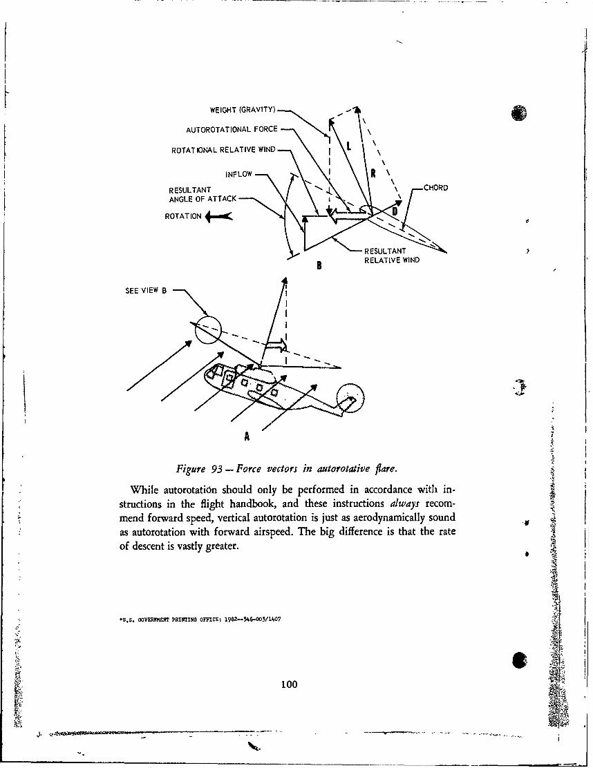
WEIGHT (GRAVITY) --111
AUTOROTATIONAL FORCE -
ROTATIONAL RELATIVE WIND L
INFLOW r R \
RESULTANT f CHORD
ANGLE OF ATTACK .
ROTATION D '
RESULTANT
B RELATIVE WIND
SEE VIEW B I
- .
A
Figure 93- Force vectors in autorotative flare.
While autorotatidn should only be performed in accordance with in- R
structions in the flight handbook, and these instructions always recom-mend forward speed, vertical autorotation is just as aerodynamically soundas autorotation with forward airspeed. The big difference is that the rate 2of descent is vastly greater.
*U.S. GOVERNMENIT PRINTING OFFICE: 1982-546-003/1407
100