ittybitty rc timer/oscillator - microchip technology
TRANSCRIPT
2017-2019 Microchip Technology Inc. DS20005730B-page 1
MIC1555/57
Features• +2.7V to +18V Operation• Low Current
- <1 μA Typical Shutdown Mode (MIC1557)- 200 μA Typical (TRG and THR Low) at 3V
Supply• Timing from Microseconds to Hours• “Zero” Leakage Trigger and Threshold Inputs• 50% Square Wave with One Resistor, One
Capacitor• Threshold Input Precedence Over Trigger Input• <15Ω Output On-Resistance• No Output Cross-Conduction Current Spikes• <0.005%/°C Temperature Stability• <0.055%/V Supply Stability• 10-pin Ultra-Thin DFN Package (2 mm × 2 mm ×
0.4 mm)• Small SOT-23-5 Surface Mount Package
Applications• Precision Timer• Pulse Generation• Sequential Timing• Time-Delay Generation• Missing Pulse Detector• Micropower Oscillator to 5 MHz• Charge-Pump Driver• LED Blinker• Voltage Converter• Linear Sweep Generator• Variable Frequency and Duty Cycle Oscillator
General DescriptionThe MIC1555 IttyBitty CMOS RC timer/oscillator andMIC1557 IttyBitty CMOS RC oscillator are designed toprovide rail-to-rail pulses for precise time delay orfrequency generation.These devices are similar in function to the industrystandard “555”, without a frequency control (FC) pin oran open-collector discharge (D) pin. The threshold pin(THR) has precedence over the trigger (TRG) input,ensuring that the BiCMOS output is off when TRG ishigh.The MIC1555 can be used as an astable (oscillator) ormonostable (one-shot) with separate threshold andtrigger inputs. In the one-shot mode, the output pulsewidth is precisely controlled by an external resistor anda capacitor. Time delays may be accurately controlledfrom microseconds to hours. In the oscillator mode, theoutput is used to provide precise feedback, with aminimum of one resistor and one capacitor producing a50% duty cycle square wave.The MIC1557 is designed for astable (oscillator)operation only, with a chip select/reset (CS) input forlow power shut-down. One resistor and one capacitorprovide a 50% duty cycle square wave. Other dutycycle ratios may be produced using two diodes and tworesistors.The MIC1555/7 are powered from a +2.7V to +18Vsupply voltage and are rated for –40°C to +85°Cambient temperature range. The MIC1555/7 areavailable in SOT-23-5, and thin SOT23-5 5-pinpackages. A low profile, ultra-thin UTDFN version ofthe MIC1555 (with chip select) is also available.
IttyBitty RC Timer/Oscillator

MIC1555/57
DS20005730B-page 2 2017-2019 Microchip Technology Inc.
Package Types
Typical Application Circuits
MIC15555-PIN SOT-23 (M5)
(TOP VIEW)
MIC15555-PIN TSOT-23 (D5)
(TOP VIEW)
MIC155510-PIN UTDFN (MU)
(TOP VIEW)
MIC15575-PIN SOT-23 (M5)
(TOP VIEW)
MIC15575-PIN TSOT-23 (D5)
(TOP VIEW)
MIC1555MONOSTABLE (ONE-SHOT)
MIC1555MONOSTABLE WITH ENABLE
MIC1557ASTABLE (OSCILLATOR)
2017-2019 Microchip Technology Inc. DS20005730B-page 3
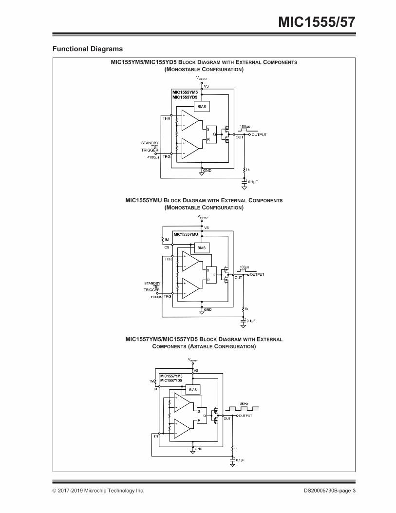
MIC1555/57Functional Diagrams
MIC155YM5/MIC155YD5 BLOCK DIAGRAM WITH EXTERNAL COMPONENTS (MONOSTABLE CONFIGURATION)
MIC1555YMU BLOCK DIAGRAM WITH EXTERNAL COMPONENTS (MONOSTABLE CONFIGURATION)
MIC1557YM5/MIC1557YD5 BLOCK DIAGRAM WITH EXTERNAL COMPONENTS (ASTABLE CONFIGURATION)

MIC1555/57
DS20005730B-page 4 2017-2019 Microchip Technology Inc.
1.0 ELECTRICAL CHARACTERISTICSAbsolute Maximum Ratings †Supply Voltage (VS).................................................................................................................................................. +22VThreshold Voltage (VTHR, VT/T) ................................................................................................................................ +22VTrigger Voltage (VTGR, VT/T) .................................................................................................................................... +22VESD HBM Rating (Note 1)..........................................................................................................................................2 kVESD MM Rating (Note 1).......................................................................................................................................... 200V
Operating Ratings ‡Supply Voltage (VS)....................................................................................................................................+2.7V to +18V
† Notice: Stresses above those listed under “Absolute Maximum Ratings” may cause permanent damage to the device.This is a stress rating only and functional operation of the device at those or any other conditions above those indicatedin the operational sections of this specification is not intended. Exposure to maximum rating conditions for extendedperiods may affect device reliability.‡ Notice: The device is not guaranteed to function outside its operating ratings.
Note 1: Devices are ESD protected, however handling precautions recommended.
2017-2019 Microchip Technology Inc. DS20005730B-page 5
MIC1555/57
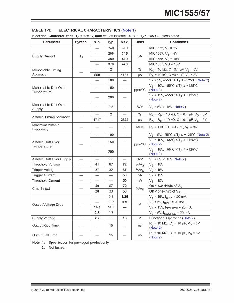
TABLE 1-1: ELECTRICAL CHARACTERISTICS (Note 1) Electrical Characteristics: TA = +25°C, bold values indicate –40°C ≤ TA ≤ +85°C, unless noted.
Parameter Symbol Min. Typ. Max. Units Conditions
Supply Current IS
— 240 300
μA
MIC1555, VS = 5V— 255 315 MIC1557, VS = 5V— 350 400 MIC1555, VS = 15V— 370 420 MIC1557, VS = 15V
Monostable Timing Accuracy —
— 2 — % RA = 10 kΩ, C =0.1 μF, VS = 5V858 — 1161 μs RA = 10 kΩ, C =0.1 μF, VS = 5V
Monostable Drift Over Temperature —
— 100 —
ppm/°C
VS = 5V, –55°C ≤ TA ≤ +125°C (Note 2)
— 150 — VS = 10V, –55°C ≤ TA ≤ +125°C (Note 2)
— 200 — VS = 15V, –55°C ≤ TA ≤ +125°C (Note 2)
Monostable Drift Over Supply — — 0.5 — %/V VS = 5V to 15V (Note 2)
Astable Timing Accuracy —— 2 — % RA = RB = 10 kΩ, C = 0.1 μF, VS = 5V
1717 — 2323 μs RA = RB = 10 kΩ, C = 0.1 μF, VS = 5VMaximum Astable Frequency — — — 5 MHz RT = 1 kΩ, CT = 47 pF, VS = 8V
Astable Drift Over Temperature —
— 100 —
ppm/°C
VS = 5V, –55°C ≤ TA ≤ +125°C (Note 2)
— 150 — VS = 10V, –55°C ≤ TA ≤ +125°C (Note 2)
— 200 — VS = 15V, –55°C ≤ TA ≤ +125°C (Note 2)
Astable Drift Over Supply — — 0.5 — %/V VS = 5V to 15V (Note 2)Threshold Voltage — 61 67 72 %/VS VS = 15VTrigger Voltage — 27 32 37 %/VS VS = 15VTrigger Current — — — 50 nA VS = 15VThreshold Current — — — 50 nA VS = 15V
Chip Select —50 67 72
%/VSOn > two-thirds of VS
28 33 50 Off < one-third of VS
Output Voltage Drop —
— 0.3 1.25
V
VS = 15V, ISINK = 20 mA— 0.08 0.5 VS = 5V, ISINK = 20 mA
14.1 14.7 — VS = 15V, ISOURCE = 20 mA3.8 4.7 — VS = 5V, ISOURCE = 20 mA
Supply Voltage — 2.7 — 18 V Functional Operation (Note 2)
Output Rise Time — — 15 — ns RL = 10 MΩ, CL = 10 pF, VS = 5V (Note 2)
Output Fall Time — — 15 — ns RL = 10 MΩ, CL = 10 pF, VS = 5V (Note 2)
Note 1: Specification for packaged product only.2: Not tested.
MIC1555/57
DS20005730B-page 6 2017-2019 Microchip Technology Inc.
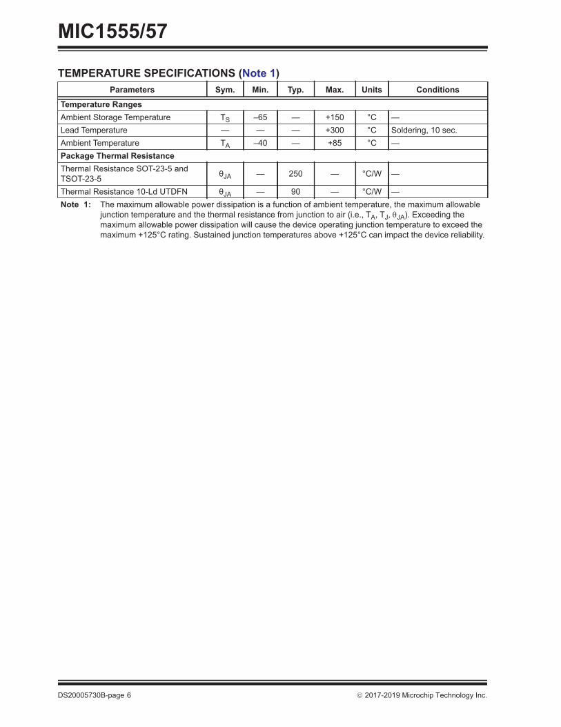
TEMPERATURE SPECIFICATIONS (Note 1)Parameters Sym. Min. Typ. Max. Units Conditions
Temperature RangesAmbient Storage Temperature TS –65 — +150 °C —Lead Temperature — — — +300 °C Soldering, 10 sec.Ambient Temperature TA –40 — +85 °C —Package Thermal ResistanceThermal Resistance SOT-23-5 and TSOT-23-5 θJA — 250 — °C/W —
Thermal Resistance 10-Ld UTDFN θJA — 90 — °C/W —Note 1: The maximum allowable power dissipation is a function of ambient temperature, the maximum allowable
junction temperature and the thermal resistance from junction to air (i.e., TA, TJ, JA). Exceeding the maximum allowable power dissipation will cause the device operating junction temperature to exceed the maximum +125°C rating. Sustained junction temperatures above +125°C can impact the device reliability.

2017-2019 Microchip Technology Inc. DS20005730B-page 7
MIC1555/572.0 TYPICAL PERFORMANCE CURVES
FIGURE 2-1: Astable Frequency.
FIGURE 2-2: Pulse Width.
FIGURE 2-3: On Resistance vs. Supply Voltage.
FIGURE 2-4: On Resistance vs. Temperature.
FIGURE 2-5: Supply Current vs. Temperature.
FIGURE 2-6: Supply Current vs. Supply Voltage.
Note: The graphs and tables provided following this note are a statistical summary based on a limited number ofsamples and are provided for informational purposes only. The performance characteristics listed hereinare not tested or guaranteed. In some graphs or tables, the data presented may be outside the specifiedoperating range (e.g., outside specified power supply range) and therefore outside the warranted range.

MIC1555/57
DS20005730B-page 8 2017-2019 Microchip Technology Inc.
FIGURE 2-7: k Factors Times RC.
FIGURE 2-8: MIC1555YMU and MIC1557 Chip Select vs. Supply Voltage.

2017-2019 Microchip Technology Inc. DS20005730B-page 9
MIC1555/573.0 PIN DESCRIPTIONSThe descriptions of the pins are listed in Table 3-1, Table 3-2, and .
TABLE 3-1: PIN FUNCTION TABLE, MIC1555 SOT-23 AND TSOT-23Pin Number Pin Name Description
1 VS Supply (Input): +2.7V to +18V supply.2 GND Ground: Supply return.3 OUT Output: CMOS totem-pole output.4 TRG Trigger (Input): Sets output high. Active-low (at ≤2/3VS nominal).5 THG Threshold (Dominant Input): Sets output low. Active-high (at ≥2/3VS nominal).
TABLE 3-2: PIN FUNCTION TABLE, MIC1555 UTDFNPin Number Pin Name Description
1 VS Supply (Input): +2.7 to +18V supply.2 CS Chip Select/Reset (Input): Active-high at >2/3VS. Output off when low at <1/3VS. If chip
select functionality is not desired, CS may be connected directly to VS.3, 4, 7, 9 NC No Connect. This pin is not internally connected.
5 THR Threshold (Dominant Input): Sets output low. Active-high (at ≥ 2/3VS nominal).6 TRG Trigger (Input): Sets output high. Active-low (at ≤2/3VS nominal).8 GND Ground. Supply return.10 OUT Output: CMOS totem-pole output
TABLE 3-3: PIN FUNCTION TABLE, MIC1557 SOT-23 AND TSOT-23Pin Number Pin Name Description
1 T/T Trigger/Threshold (Input): Internally connected to both threshold and trigger functions. When the voltage at this pin is ≤2/3VS, it will set the output high. When the voltage at this pin is ≥2/3VS, it will set the output low.
2 GND Ground: Supply return.3 CS Chip Select/Reset (Input): Active-high at >2/3VS. Output off when low at <1/3VS. If chip
select functionality is not desired, CS may be connected directly to VS.4 VS Supply (Input): +2.7 to +18V supply.5 OUT Output: CMOS totem-pole output.
MIC1555/57
DS20005730B-page 10 2017-2019 Microchip Technology Inc.
4.0 FUNCTIONAL DESCRIPTIONThe MIC1555/7 provides the logic for creating simpleRC timer or oscillator circuits.The MIC1555 has separate THR (threshold) and TRG(trigger) connections for monostable (one-shot) orastable (oscillator) operation.The MIC1557 has a single T/T (threshold and trigger)connection for astable (oscillator) operation only. TheMIC1557 includes a CS (chip select/reset) control.For more information, refer to the Functional Diagramsfor MIC1555 and MIC1557.
4.1 SupplyVoltage supply (VS) is rated for +2.7V to +18V. Anexternal capacitor is recommended to decouple noise.
4.2 Resistive DividerThe resistive voltage divider is constructed of threeequal value resistors to produce 1/3VS and 2/3VSvoltage for trigger and threshold reference voltages.
4.3 Chip Select/Reset (MIC1555YMU and MIC1557 only)
Chip select/reset (CS) controls the bias supply to theoscillator’s internal circuitry. CS must be connected toCMOS logic-high or logic-low levels. Floating CS willresult in unpredictable operation. When the chip isdeselected, the supply current is less than 1 μA.Forcing CS low resets the device by setting the flip flop,forcing the output low. If Chip Select functionality is notdesired, CS may be connected directly to VS.
4.4 Threshold ComparatorThe threshold comparator is connected to S (set) onthe RS flip-flop. When the threshold voltage (2/3VS) isreached, the flip-flop is set, making the output low. THRis dominant over TRG.
4.5 Trigger ComparatorThe trigger comparator is connected to R (reset) on theRS flip-flop. When TRG (trigger) goes below the triggervoltage (1/3VS), the flip-flop resets, making the outputhigh.
4.6 Flip-Flop and OutputA reset signal causes Q to go low, turning on theP-channel MOSFET and turning off the N-channelMOSFET. This makes the output rise to nearly VS.A set signal causes Q to go high, turning off theP-channel MOSFET, and turning on the N-channelMOSFET, grounding OUT.
4.7 Basic Monostable OperationA momentary low signal applied to TRG causes theoutput to go high. The external capacitor chargesslowly through the external resistor. When thresholdvoltage (VTHR) reaches 2/3VS, the output is switchedoff, discharging the capacitor. During power-on, asingle pulse may be generated.For more information, refer to the Functional Diagramsfor MIC1555.
4.8 Basic Astable OperationThe MIC1557 starts with T/T low, causing the output togo high. The external capacitor charges slowly throughthe external resistor. When VT/T reaches 2/3VS(threshold voltage), the output is switched off, slowlydischarging the capacitor. When VT/T decreases to1/3VS (trigger voltage), the output is switched on,causing VT/T to rise again, repeating the cycle.For more information, refer to the Functional Diagramsfor MIC1557.
2017-2019 Microchip Technology Inc. DS20005730B-page 11
MIC1555/575.0 APPLICATION INFORMATION
5.1 Basic Monostable (One-Shot) Circuit
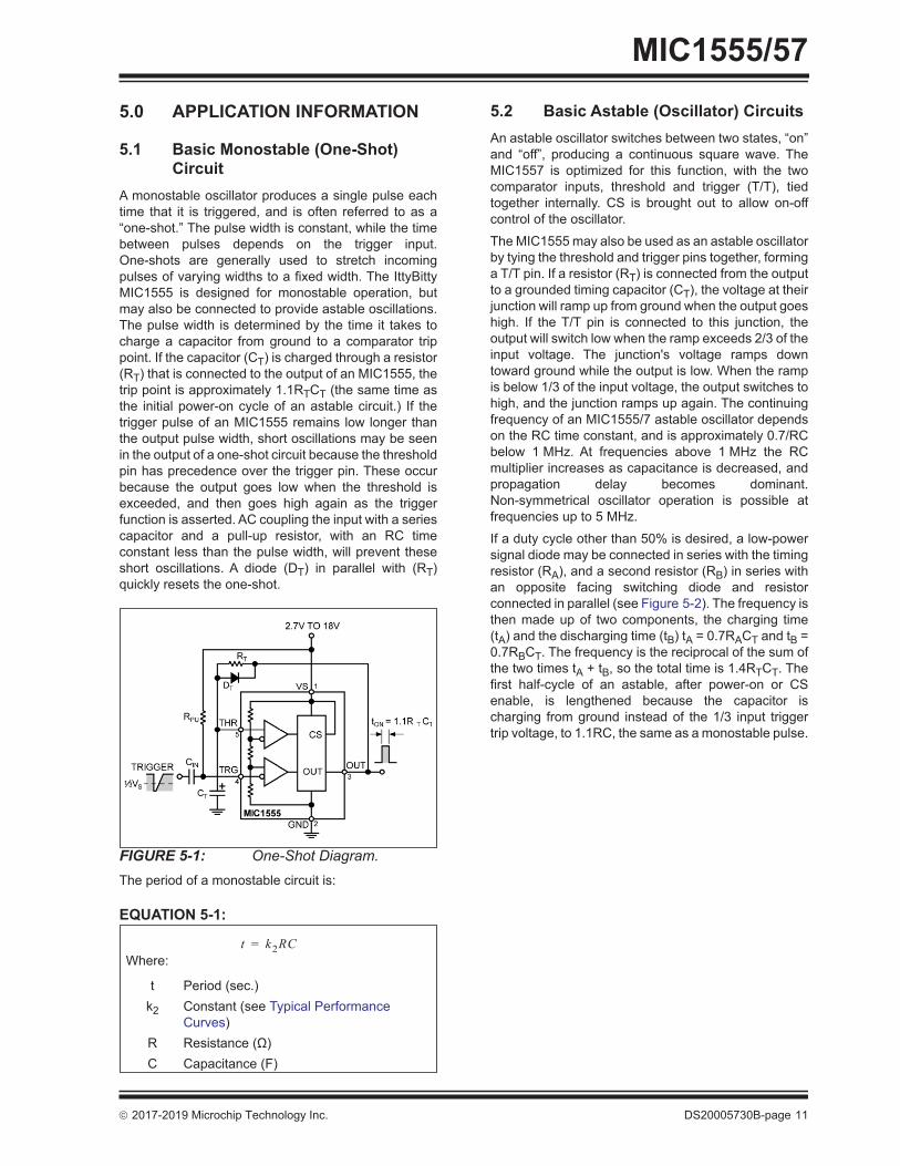
A monostable oscillator produces a single pulse eachtime that it is triggered, and is often referred to as a“one-shot.” The pulse width is constant, while the timebetween pulses depends on the trigger input.One-shots are generally used to stretch incomingpulses of varying widths to a fixed width. The IttyBittyMIC1555 is designed for monostable operation, butmay also be connected to provide astable oscillations.The pulse width is determined by the time it takes tocharge a capacitor from ground to a comparator trippoint. If the capacitor (CT) is charged through a resistor(RT) that is connected to the output of an MIC1555, thetrip point is approximately 1.1RTCT (the same time asthe initial power-on cycle of an astable circuit.) If thetrigger pulse of an MIC1555 remains low longer thanthe output pulse width, short oscillations may be seenin the output of a one-shot circuit because the thresholdpin has precedence over the trigger pin. These occurbecause the output goes low when the threshold isexceeded, and then goes high again as the triggerfunction is asserted. AC coupling the input with a seriescapacitor and a pull-up resistor, with an RC timeconstant less than the pulse width, will prevent theseshort oscillations. A diode (DT) in parallel with (RT)quickly resets the one-shot.
FIGURE 5-1: One-Shot Diagram.The period of a monostable circuit is:
EQUATION 5-1:
5.2 Basic Astable (Oscillator) CircuitsAn astable oscillator switches between two states, “on”and “off”, producing a continuous square wave. TheMIC1557 is optimized for this function, with the twocomparator inputs, threshold and trigger (T/T), tiedtogether internally. CS is brought out to allow on-offcontrol of the oscillator.The MIC1555 may also be used as an astable oscillatorby tying the threshold and trigger pins together, forminga T/T pin. If a resistor (RT) is connected from the outputto a grounded timing capacitor (CT), the voltage at theirjunction will ramp up from ground when the output goeshigh. If the T/T pin is connected to this junction, theoutput will switch low when the ramp exceeds 2/3 of theinput voltage. The junction's voltage ramps downtoward ground while the output is low. When the rampis below 1/3 of the input voltage, the output switches tohigh, and the junction ramps up again. The continuingfrequency of an MIC1555/7 astable oscillator dependson the RC time constant, and is approximately 0.7/RCbelow 1 MHz. At frequencies above 1 MHz the RCmultiplier increases as capacitance is decreased, andpropagation delay becomes dominant.Non-symmetrical oscillator operation is possible atfrequencies up to 5 MHz.If a duty cycle other than 50% is desired, a low-powersignal diode may be connected in series with the timingresistor (RA), and a second resistor (RB) in series withan opposite facing switching diode and resistorconnected in parallel (see Figure 5-2). The frequency isthen made up of two components, the charging time(tA) and the discharging time (tB) tA = 0.7RACT and tB =0.7RBCT. The frequency is the reciprocal of the sum ofthe two times tA + tB, so the total time is 1.4RTCT. Thefirst half-cycle of an astable, after power-on or CSenable, is lengthened because the capacitor ischarging from ground instead of the 1/3 input triggertrip voltage, to 1.1RC, the same as a monostable pulse.
t k2RC=Where:
t Period (sec.)k2 Constant (see Typical Performance
Curves)R Resistance (Ω)C Capacitance (F)

MIC1555/57
DS20005730B-page 12 2017-2019 Microchip Technology Inc.
FIGURE 5-2: Oscillator Diagram.The MIC1555 or MIC1557 can be used to construct anoscillator.The frequency of an astable oscillator is:
EQUATION 5-2:
To use the MIC1555 as an oscillator, connect TRG toTHR.
FIGURE 5-3: MIC1555 Oscillator Configuration.
The MIC1555YMU and MIC1557 feature a CS input.With a logic-low signal, CS places the part into a <1 μAshutdown state. If unused, the CS input must be pulledup.
FIGURE 5-4: MIC1557 Oscillator Configuration.
5.3 Falling-Edge Triggered Monostable Circuit
The MIC1555 may be triggered by an AC-coupledfalling edge, as shown in Figure 5-5. The RC timeconstant of the input capacitor and pull-up resistorshould be less than the output pulse time, to preventmultiple output pulses. A diode across the timingresistor provides a fast reset at the end of the positivetiming pulse.
FIGURE 5-5: Falling Edge Trigger Configuration.
5.4 Rising-Edge Triggered Monostable Circuit
The MIC1555 may be triggered by an AC-coupledrising edge, as shown in Figure 5-6. The pulse beginswhen the AC-coupled input rises, and a diode from theoutput holds the THR input low until TRG discharges to1/3VS. This circuit provides a low-going output pulse.
f 1k1RC--------------=
Where:
f Frequency (Hz)k1 Constant (see Typical Performance
Curves)R Resistance (Ω)C Capacitance (F)

2017-2019 Microchip Technology Inc. DS20005730B-page 13
MIC1555/57
FIGURE 5-6: Rising Edge Trigger Configuration.
5.5 AccuracyThe two comparators in the MIC1555/7 use a resistorvoltage divider to set the threshold and trigger trippoints to approximately 2/3 and 1/3 of the input voltage,respectively. Because the charge and discharge ratesof an RC circuit are dependent on the applied voltage,the timing remains constant if the input voltage varies.If a duty cycle of exactly 50% (or any other value from1 to 99%), two resistors (or a variable resistor) and twodiodes are needed to vary the charge and dischargetimes. The forward voltage of diodes varies withtemperature, so some change in frequency will be seenwith temperature extremes, but the duty cycle shouldtrack. For absolute timing accuracy, the MIC1555/7output could be used to control constant currentsources to linearly charge and discharge the capacitor,at the expense of added components and board space.
5.6 Long Time DelaysTiming resistors larger than 1 MΩ or capacitors largerthan 10 μF are not recommended due to leakagecurrent inaccuracies. Time delays greater than 10seconds are more accurately produced by dividing theoutput of an oscillator by a chain of flip-flop counterstages. To produce an accurate one-hour delay, forexample, divide a 4.55 Hz MIC1557 oscillator by16,384 (4000hex, 214) using a CD4020 CMOS divider.4.5 Hz may be generated with a 1 μF CT andapproximately 156 kΩ.
5.7 Inverting Schmitt TriggerAs shown in Figure 5-7, the trip points of theMIC1555/7 are defined as 1/3VS and 2/3VS, whichallows either device to be used as a signal conditioninginverter, with hysteresis. A slowly changing input on T/Twill be converted to a fast rise or fall-time oppositedirection rail-to-rail output voltage. This output maybeused to directly drive the gate of a logic-level P-channelMOSFET with a gate pull-up resistor. This is aninverted logic low-side logic level MOSFET driver. A
standard N-channel MOSFET may be driven by asecond MIC1555/7, powered by 12V to 15V, tolevel-shift the input.
FIGURE 5-7: Schmitt Trigger.
5.8 Charge Pump Low-Side MOSFET Drivers
A standard MOSFET requires approximately >5V tofully enhance the gate for minimum RDS(ON).Substituting a logic-level MOSFET reduces therequired gate voltage, allowing an MIC1557 to be usedas an inverting Schmitt trigger, described above. AnMIC1557 may be configured as a voltage quadrupler toboost a 5V input to over 15V to fully enhance anN-channel MOSFET which may have its drainconnected to a higher voltage, through a high-sideload. A TTL-high signal applied to CS enables a 10 kHzoscillator, which quickly develops 15V at the gate of theMOSFET, clamped by a Zener diode. A resistor fromthe gate to ground ensures that the FET will turn offquickly when the MIC1557 is turned off.
FIGURE 5-8: Charge Pump.
5.9 Audible VoltmeterIf an additional charge or discharge source isconnected to the timing capacitor, the frequency maybe shifted by turning the source on or off. An MIC1555oscillator, powered by the circuit under test, may beused to drive a small loud speaker or piezo-electrictransducer to provide a medium frequency for an openor high impedance state at the probe. A high tone isgenerated for a high level, and a lower frequency for alogic low on the probe.

MIC1555/57
DS20005730B-page 14 2017-2019 Microchip Technology Inc.
FIGURE 5-9: Audible Voltmeter.

2017-2019 Microchip Technology Inc. DS20005730B-page 15
MIC1555/576.0 PACKAGING INFORMATION
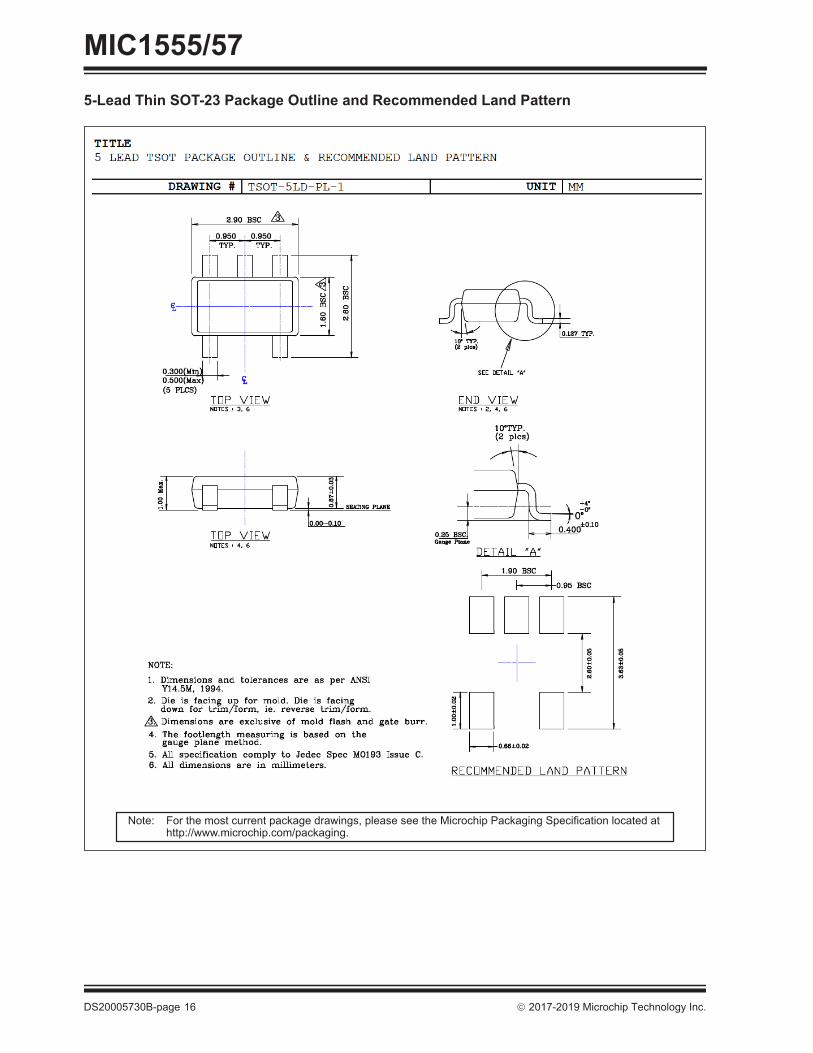
5-Lead SOT-23 Package Outline and Recommended Land Pattern
Note: For the most current package drawings, please see the Microchip Packaging Specification located at http://www.microchip.com/packaging.
MIC1555/57
DS20005730B-page 16 2017-2019 Microchip Technology Inc.
5-Lead Thin SOT-23 Package Outline and Recommended Land Pattern
Note: For the most current package drawings, please see the Microchip Packaging Specification located at http://www.microchip.com/packaging.

2017-2019 Microchip Technology Inc. DS20005730B-page 17
MIC1555/5710-Lead 2 mm x 2 mm UTDFN Package Outline and Recommended Land Pattern
Note: For the most current package drawings, please see the Microchip Packaging Specification located at http://www.microchip.com/packaging.

MIC1555/57
DS20005730B-page 18 2017-2019 Microchip Technology Inc.
NOTES:

2017-2019 Microchip Technology Inc. DS20005730B-page 19
MIC1555/57APPENDIX A: REVISION HISTORY
Revision A (March 2017)• Converted Micrel document MIC1555/57 to Micro-
chip data sheet DS20005730A.• Minor text changes throughout.• Updated Supply Current values for MIC1557 in
Section 1.0 “Electrical Characteristics”.
Revision B (April 2019)• Corrected part number and package type in the
Package Types section.

MIC1555/57
DS20005730B-page 20 2017-2019 Microchip Technology Inc.
NOTES:

2017-2019 Microchip Technology Inc. DS20005730B-page 21
MIC1555/57PRODUCT IDENTIFICATION SYSTEMTo order or obtain information, e.g., on pricing or delivery, contact your local Microchip representative or sales office.
Examples:a) MIC1555YM5-TR: IttyBitty RC Timer/Oscillator
–40°C to +85°C Temp. Range,5-Lead SOT-23, 3,000/Reel
b) MIC1555YD5-TR: IttyBitty RC Timer/Oscillator –40°C to +85°C Temp. Range,5-Lead TSOT-23, 3,000/Reel
c) MIC1555YMU-T5: IttyBitty RC Timer/Oscillator –40°C to +85°C Temp. Range,10-Lead UTDFN, 500/Reel
d) MIC1555YMU-TR: IttyBitty RC Timer/Oscillator –40°C to +85°C Temp. Range,10-Lead UTDFN, 5,000/Reel
e) MIC1557YM5-TR: IttyBitty RC Timer/Oscillator –40°C to +85°C Temp. Range,5-Lead SOT-23, 3,000/Reel
f) MIC1557YD5-TR: IttyBitty RC Timer/Oscillator –40°C to +85°C Temp. Range,5-Lead TSOT-23, 3,000/Reel
PART NO. X
PackageDevice
Device: MIC1555: IttyBitty RC Timer/OscillatorMIC1557: IttyBitty RC Timer/Oscillator
Temperature: Y = –40°C to +85°C
Package: M5 = 5-Lead SOT-23D5 = 5-Lead Thin SOT-23MU = 10-Lead 2 mm x 2 mm UTDFN
Media Type: TR = 3,000/Reel (SOT-23, TSOT-23)TR = 5,000/Reel (UTDFN)T5 = 500/Reel (UTDFN)
X
Temperature
XX –
Media Type
Note 1: Tape and Reel identifier only appears in the catalog part number description. This identifier is used for ordering purposes and is not printed on the device package. Check with your Microchip Sales Office for package availability with the Tape and Reel option.

MIC1555/57
DS20005730B-page 22 2017-2019 Microchip Technology Inc.
NOTES:

2017-2019 Microchip Technology Inc. DS20005730B-page 23
Information contained in this publication regarding deviceapplications and the like is provided only for your convenienceand may be superseded by updates. It is your responsibility toensure that your application meets with your specifications.MICROCHIP MAKES NO REPRESENTATIONS ORWARRANTIES OF ANY KIND WHETHER EXPRESS ORIMPLIED, WRITTEN OR ORAL, STATUTORY OROTHERWISE, RELATED TO THE INFORMATION,INCLUDING BUT NOT LIMITED TO ITS CONDITION,QUALITY, PERFORMANCE, MERCHANTABILITY ORFITNESS FOR PURPOSE. Microchip disclaims all liabilityarising from this information and its use. Use of Microchipdevices in life support and/or safety applications is entirely atthe buyer’s risk, and the buyer agrees to defend, indemnify andhold harmless Microchip from any and all damages, claims,suits, or expenses resulting from such use. No licenses areconveyed, implicitly or otherwise, under any Microchipintellectual property rights unless otherwise stated.
TrademarksThe Microchip name and logo, the Microchip logo, AnyRate, AVR, AVR logo, AVR Freaks, BitCloud, chipKIT, chipKIT logo, CryptoMemory, CryptoRF, dsPIC, FlashFlex, flexPWR, Heldo, JukeBlox, KeeLoq, Kleer, LANCheck, LINK MD, maXStylus, maXTouch, MediaLB, megaAVR, MOST, MOST logo, MPLAB, OptoLyzer, PIC, picoPower, PICSTART, PIC32 logo, Prochip Designer, QTouch, SAM-BA, SpyNIC, SST, SST Logo, SuperFlash, tinyAVR, UNI/O, and XMEGA are registered trademarks of Microchip Technology Incorporated in the U.S.A. and other countries.ClockWorks, The Embedded Control Solutions Company, EtherSynch, Hyper Speed Control, HyperLight Load, IntelliMOS, mTouch, Precision Edge, and Quiet-Wire are registered trademarks of Microchip Technology Incorporated in the U.S.A.Adjacent Key Suppression, AKS, Analog-for-the-Digital Age, Any Capacitor, AnyIn, AnyOut, BodyCom, CodeGuard, CryptoAuthentication, CryptoAutomotive, CryptoCompanion, CryptoController, dsPICDEM, dsPICDEM.net, Dynamic Average Matching, DAM, ECAN, EtherGREEN, In-Circuit Serial Programming, ICSP, INICnet, Inter-Chip Connectivity, JitterBlocker, KleerNet, KleerNet logo, memBrain, Mindi, MiWi, motorBench, MPASM, MPF, MPLAB Certified logo, MPLIB, MPLINK, MultiTRAK, NetDetach, Omniscient Code Generation, PICDEM, PICDEM.net, PICkit, PICtail, PowerSmart, PureSilicon, QMatrix, REAL ICE, Ripple Blocker, SAM-ICE, Serial Quad I/O, SMART-I.S., SQI, SuperSwitcher, SuperSwitcher II, Total Endurance, TSHARC, USBCheck, VariSense, ViewSpan, WiperLock, Wireless DNA, and ZENA are trademarks of Microchip Technology Incorporated in the U.S.A. and other countries.SQTP is a service mark of Microchip Technology Incorporated in the U.S.A.Silicon Storage Technology is a registered trademark of Microchip Technology Inc. in other countries.GestIC is a registered trademark of Microchip Technology Germany II GmbH & Co. KG, a subsidiary of Microchip Technology Inc., in other countries. All other trademarks mentioned herein are property of their respective companies.© 2017-2019, Microchip Technology Incorporated, All Rights Reserved.ISBN: 978-1-5224-4376-6
Note the following details of the code protection feature on Microchip devices:• Microchip products meet the specification contained in their particular Microchip Data Sheet.
• Microchip believes that its family of products is one of the most secure families of its kind on the market today, when used in the intended manner and under normal conditions.
• There are dishonest and possibly illegal methods used to breach the code protection feature. All of these methods, to our knowledge, require using the Microchip products in a manner outside the operating specifications contained in Microchip’s Data Sheets. Most likely, the person doing so is engaged in theft of intellectual property.
• Microchip is willing to work with the customer who is concerned about the integrity of their code.
• Neither Microchip nor any other semiconductor manufacturer can guarantee the security of their code. Code protection does not mean that we are guaranteeing the product as “unbreakable.”
Code protection is constantly evolving. We at Microchip are committed to continuously improving the code protection features of ourproducts. Attempts to break Microchip’s code protection feature may be a violation of the Digital Millennium Copyright Act. If such actsallow unauthorized access to your software or other copyrighted work, you may have a right to sue for relief under that Act.
Microchip received ISO/TS-16949:2009 certification for its worldwide headquarters, design and wafer fabrication facilities in Chandler and Tempe, Arizona; Gresham, Oregon and design centers in California and India. The Company’s quality system processes and procedures are for its PIC® MCUs and dsPIC® DSCs, KEELOQ® code hopping devices, Serial EEPROMs, microperipherals, nonvolatile memory and analog products. In addition, Microchip’s quality system for the design and manufacture of development systems is ISO 9001:2000 certified.

DS20005730B-page 24 2017-2019 Microchip Technology Inc.
AMERICASCorporate Office2355 West Chandler Blvd.Chandler, AZ 85224-6199Tel: 480-792-7200 Fax: 480-792-7277Technical Support: http://www.microchip.com/supportWeb Address: www.microchip.comAtlantaDuluth, GA Tel: 678-957-9614 Fax: 678-957-1455Austin, TXTel: 512-257-3370 BostonWestborough, MA Tel: 774-760-0087 Fax: 774-760-0088ChicagoItasca, IL Tel: 630-285-0071 Fax: 630-285-0075DallasAddison, TX Tel: 972-818-7423 Fax: 972-818-2924DetroitNovi, MI Tel: 248-848-4000Houston, TX Tel: 281-894-5983IndianapolisNoblesville, IN Tel: 317-773-8323Fax: 317-773-5453Tel: 317-536-2380Los AngelesMission Viejo, CA Tel: 949-462-9523Fax: 949-462-9608Tel: 951-273-7800 Raleigh, NC Tel: 919-844-7510New York, NY Tel: 631-435-6000San Jose, CA Tel: 408-735-9110Tel: 408-436-4270Canada - TorontoTel: 905-695-1980 Fax: 905-695-2078
ASIA/PACIFICAustralia - SydneyTel: 61-2-9868-6733China - BeijingTel: 86-10-8569-7000 China - ChengduTel: 86-28-8665-5511China - ChongqingTel: 86-23-8980-9588China - DongguanTel: 86-769-8702-9880 China - GuangzhouTel: 86-20-8755-8029 China - HangzhouTel: 86-571-8792-8115 China - Hong Kong SARTel: 852-2943-5100 China - NanjingTel: 86-25-8473-2460China - QingdaoTel: 86-532-8502-7355China - ShanghaiTel: 86-21-3326-8000 China - ShenyangTel: 86-24-2334-2829China - ShenzhenTel: 86-755-8864-2200 China - SuzhouTel: 86-186-6233-1526 China - WuhanTel: 86-27-5980-5300China - XianTel: 86-29-8833-7252China - XiamenTel: 86-592-2388138 China - ZhuhaiTel: 86-756-3210040
ASIA/PACIFICIndia - BangaloreTel: 91-80-3090-4444 India - New DelhiTel: 91-11-4160-8631India - PuneTel: 91-20-4121-0141Japan - OsakaTel: 81-6-6152-7160 Japan - TokyoTel: 81-3-6880- 3770 Korea - DaeguTel: 82-53-744-4301Korea - SeoulTel: 82-2-554-7200Malaysia - Kuala LumpurTel: 60-3-7651-7906Malaysia - PenangTel: 60-4-227-8870Philippines - ManilaTel: 63-2-634-9065SingaporeTel: 65-6334-8870Taiwan - Hsin ChuTel: 886-3-577-8366Taiwan - KaohsiungTel: 886-7-213-7830Taiwan - TaipeiTel: 886-2-2508-8600 Thailand - BangkokTel: 66-2-694-1351Vietnam - Ho Chi MinhTel: 84-28-5448-2100
EUROPEAustria - WelsTel: 43-7242-2244-39Fax: 43-7242-2244-393Denmark - CopenhagenTel: 45-4450-2828 Fax: 45-4485-2829Finland - EspooTel: 358-9-4520-820France - ParisTel: 33-1-69-53-63-20 Fax: 33-1-69-30-90-79 Germany - GarchingTel: 49-8931-9700Germany - HaanTel: 49-2129-3766400Germany - HeilbronnTel: 49-7131-67-3636Germany - KarlsruheTel: 49-721-625370Germany - MunichTel: 49-89-627-144-0 Fax: 49-89-627-144-44Germany - RosenheimTel: 49-8031-354-560Israel - Ra’anana Tel: 972-9-744-7705Italy - Milan Tel: 39-0331-742611 Fax: 39-0331-466781Italy - PadovaTel: 39-049-7625286 Netherlands - DrunenTel: 31-416-690399 Fax: 31-416-690340Norway - TrondheimTel: 47-7288-4388Poland - WarsawTel: 48-22-3325737 Romania - BucharestTel: 40-21-407-87-50Spain - MadridTel: 34-91-708-08-90Fax: 34-91-708-08-91Sweden - GothenbergTel: 46-31-704-60-40Sweden - StockholmTel: 46-8-5090-4654UK - WokinghamTel: 44-118-921-5800Fax: 44-118-921-5820
Worldwide Sales and Service
08/15/18