itu-t rec. g.107 (03/2005) the e-model, a …andreaf/new/documents/other/t-rec-g.107...transmission...
TRANSCRIPT

I n t e r n a t i o n a l T e l e c o m m u n i c a t i o n U n i o n
ITU-T G.107TELECOMMUNICATION STANDARDIZATION SECTOR OF ITU
(03/2005)
SERIES G: TRANSMISSION SYSTEMS AND MEDIA, DIGITAL SYSTEMS AND NETWORKS International telephone connections and circuits – General definitions
The E-model, a computational model for use in transmission planning
ITU-T Recommendation G.107

ITU-T G-SERIES RECOMMENDATIONS TRANSMISSION SYSTEMS AND MEDIA, DIGITAL SYSTEMS AND NETWORKS
INTERNATIONAL TELEPHONE CONNECTIONS AND CIRCUITS G.100–G.199
General definitions G.100–G.109 General Recommendations on the transmission quality for an entire international telephone connection
G.110–G.119
General characteristics of national systems forming part of international connections G.120–G.129 General characteristics of the 4-wire chain formed by the international circuits and national extension circuits
G.130–G.139
General characteristics of the 4-wire chain of international circuits; international transit G.140–G.149 General characteristics of international telephone circuits and national extension circuits G.150–G.159 Apparatus associated with long-distance telephone circuits G.160–G.169 Transmission plan aspects of special circuits and connections using the international telephone connection network
G.170–G.179
Protection and restoration of transmission systems G.180–G.189 GENERAL CHARACTERISTICS COMMON TO ALL ANALOGUE CARRIER-TRANSMISSION SYSTEMS
G.200–G.299
INDIVIDUAL CHARACTERISTICS OF INTERNATIONAL CARRIER TELEPHONE SYSTEMS ON METALLIC LINES
G.300–G.399
GENERAL CHARACTERISTICS OF INTERNATIONAL CARRIER TELEPHONE SYSTEMS ON RADIO-RELAY OR SATELLITE LINKS AND INTERCONNECTION WITH METALLIC LINES
G.400–G.449
COORDINATION OF RADIOTELEPHONY AND LINE TELEPHONY G.450–G.499 TRANSMISSION MEDIA CHARACTERISTICS G.600–G.699 DIGITAL TERMINAL EQUIPMENTS G.700–G.799 DIGITAL NETWORKS G.800–G.899 DIGITAL SECTIONS AND DIGITAL LINE SYSTEM G.900–G.999 QUALITY OF SERVICE AND PERFORMANCE – GENERIC AND USER-RELATED ASPECTS
G.1000–G.1999
TRANSMISSION MEDIA CHARACTERISTICS G.6000–G.6999 DIGITAL TERMINAL EQUIPMENTS G.7000–G.7999 DIGITAL NETWORKS G.8000–G.8999
For further details, please refer to the list of ITU-T Recommendations.

ITU-T Rec. G.107 (03/2005) i
ITU-T Recommendation G.107
The E-model, a computational model for use in transmission planning
Summary This Recommendation gives the algorithm for the so-called E-model as the common ITU-T Transmission Rating Model. This computational model can be useful to transmission planners, to help ensure that users will be satisfied with end-to-end transmission performance. The primary output of the model is a scalar rating of transmission quality. A major feature of this model is the use of transmission impairment factors that reflect the effects of modern signal processing devices.
In the year 2000 revision, an enhanced version of the E-model was provided, in order to better take into account the effects of room noise at the send side, and quantizing distortion. With the year 2002 revision, the impairment due to random packet-loss has been included in a parametric way for different codecs. Since the 2003 version, an enhanced modelling of the quality in case of low talker sidetone levels is provided. The current revision enables more accurate quality predictions for codecs under (short-term) dependent packet loss.
Source ITU-T Recommendation G.107 was approved on 1 March 2005 by ITU-T Study Group 12 (2005-2008) under the ITU-T Recommendation A.8 procedure.

ii ITU-T Rec. G.107 (03/2005)
FOREWORD
The International Telecommunication Union (ITU) is the United Nations specialized agency in the field of telecommunications. The ITU Telecommunication Standardization Sector (ITU-T) is a permanent organ of ITU. ITU-T is responsible for studying technical, operating and tariff questions and issuing Recommendations on them with a view to standardizing telecommunications on a worldwide basis.
The World Telecommunication Standardization Assembly (WTSA), which meets every four years, establishes the topics for study by the ITU-T study groups which, in turn, produce Recommendations on these topics.
The approval of ITU-T Recommendations is covered by the procedure laid down in WTSA Resolution 1.
In some areas of information technology which fall within ITU-T's purview, the necessary standards are prepared on a collaborative basis with ISO and IEC.
NOTE
In this Recommendation, the expression "Administration" is used for conciseness to indicate both a telecommunication administration and a recognized operating agency.
Compliance with this Recommendation is voluntary. However, the Recommendation may contain certain mandatory provisions (to ensure e.g. interoperability or applicability) and compliance with the Recommendation is achieved when all of these mandatory provisions are met. The words "shall" or some other obligatory language such as "must" and the negative equivalents are used to express requirements. The use of such words does not suggest that compliance with the Recommendation is required of any party.
INTELLECTUAL PROPERTY RIGHTS
ITU draws attention to the possibility that the practice or implementation of this Recommendation may involve the use of a claimed Intellectual Property Right. ITU takes no position concerning the evidence, validity or applicability of claimed Intellectual Property Rights, whether asserted by ITU members or others outside of the Recommendation development process.
As of the date of approval of this Recommendation, ITU had not received notice of intellectual property, protected by patents, which may be required to implement this Recommendation. However, implementors are cautioned that this may not represent the latest information and are therefore strongly urged to consult the TSB patent database.
ITU 2005
All rights reserved. No part of this publication may be reproduced, by any means whatsoever, without the prior written permission of ITU.
ITU-T Rec. G.107 (03/2005) iii
CONTENTS
Page 1 General.......................................................................................................................... 1
1.1 Scope .............................................................................................................. 1 1.2 References ...................................................................................................... 1
2 The E-model, a computational model for use in transmission planning ...................... 2 2.1 Introduction .................................................................................................... 2 2.2 Source code .................................................................................................... 2
3 The structure and basic algorithms of the E-model ...................................................... 2 3.1 Calculation of the transmission rating factor, R ............................................. 3 3.2 Basic signal-to-noise ratio, Ro........................................................................ 4 3.3 Simultaneous impairment factor, Is................................................................ 4 3.4 Delay impairment factor, Id ........................................................................... 5 3.5 Equipment impairment factor, Ie.................................................................... 7 3.6 Advantage factor, A ........................................................................................ 7 3.7 Default values................................................................................................. 8
Annex A – Conditions of using the E-model........................................................................... 9 A.1 Examples of conditions where caution must be exercised when using the
E-model .......................................................................................................... 9 A.2 Conditions for which the performance of the E-model has been improved
by updating from the earlier version .............................................................. 9
Annex B – Quality measures derived from the transmission rating factor R .......................... 12
Annex C – Source code for G.107_5 in BASIC ...................................................................... 14
Appendix I – Calculation of R from MOSCQE values .............................................................. 19
BIBLIOGRAPHY.................................................................................................................... 20


ITU-T Rec. G.107 (03/2005) 1
ITU-T Recommendation G.107
The E-model, a computational model for use in transmission planning
1 General
1.1 Scope This Recommendation describes a computational model, known as the E-model, that has proven useful as a transmission planning tool, for assessing the combined effects of variations in several transmission parameters that affect conversational1 quality of 3.1 kHz handset telephony. This computational model can be used, for example, by transmission planners to help ensure that users will be satisfied with end-to-end transmission performance whilst avoiding over-engineering of networks. It must be emphasized that the primary output from the model is the "Rating Factor" R but this can be transformed to give estimates of customer opinion. Such estimates are only made for transmission planning purposes and not for actual customer opinion prediction (for which there is no agreed-upon model recommended by the ITU-T).
This revision now includes packet-loss as a new parameter, and an enhancement of the talker sidetone modelling.
The E-model has not been fully verified by field surveys or laboratory tests for the very large number of possible combinations of input parameters. For many combinations of high importance to transmission planners, the E-model can be used with confidence, but for other parameter combinations, E-model predictions have been questioned and are currently under study. Accordingly, caution must be exercised when using the E-model for some conditions; for example, the E-model may give inaccurate results for combinations of certain types of impairments. Annex A provides further information in this regard.
1.2 References The following ITU-T Recommendations and other references contain provisions which, through reference in this text, constitute provisions of this Recommendation. At the time of publication, the editions indicated were valid. All Recommendations and other references are subject to revision; users of this Recommendation are therefore encouraged to investigate the possibility of applying the most recent edition of the Recommendations and other references listed below. A list of the currently valid ITU-T Recommendations is regularly published. The reference to a document within this Recommendation does not give it, as a stand-alone document, the status of a Recommendation.
[1] ITU-T Recommendation G.100 (2001), Definitions used in Recommendations on general characteristics of international telephone connections and circuits.
[2] ITU-T Recommendation G.108 (1999), Application of the E-model: A planning guide.
[3] ITU-T Recommendation G.109 (1999), Definition of categories of speech transmission quality.
[4] ITU-T Recommendation G.113 (2001), Transmission impairments due to speech processing.
[5] ITU-T Recommendation G.113 Appendix I (2002), Provisional planning values for the equipment impairment factor Ie and packet-loss robustness factor Bpl.
____________________ 1 Conversational quality in this context refers to transmission characteristics, e.g., long transmission times,
effects of talker echoes, etc. However, the E-model as described in this Recommendation is not intended to model transmission impairments during double talk situations.
2 ITU-T Rec. G.107 (03/2005)
[6] ITU-T Recommendation P.833 (2001), Methodology for derivation of equipment impairment factors from subjective listening-only tests.
[7] ITU-T Recommendation P.834 (2002), Methodology for the derivation of equipment impairment factors from instrumental models.
[8] ITU-T Recommendation P.862 (2001), Perceptual evaluation of speech quality (PESQ): An objective method for end-to-end speech quality assessment of narrow-band telephone networks and speech codecs.
2 The E-model, a computational model for use in transmission planning
2.1 Introduction The complexity of modern networks requires that for transmission planning the many transmission parameters are not only considered individually but also that their combination effects are taken into account. This can be done by "expert, informed guessing," but a more systematic approach is desirable, such as by using a computational model. The output from the model described here is a scalar quality rating value, R, which varies directly with the overall conversational quality. ITU-T Rec. G.113 [4] gives guidance about specific impairments, including combinations effects based upon a simplification of the model. However, the output can also give nominal estimates of user reactions, for instance in the form of percentages finding the modelled connection "Good or Better" or "Poor or Worse", as described in Annex B. Furthermore, detailed guidance on the proper application of the E-model − as described in this Recommendation − is provided in ITU-T Rec. G.108 [2]. In addition, the definition of categories of speech transmission quality can be found in ITU-T Rec. G.109 [3].
2.2 Source code Annex C contains the source code in BASIC of the E-model described in this Recommendation. The purpose of this code is to ensure that users of the E-model are using consistent implementations of the formulae.
3 The structure and basic algorithms of the E-model The E-model is based on the equipment impairment factor method, following previous transmission rating models. It was developed by an ETSI ad hoc group called "Voice Transmission Quality from Mouth to Ear".
The reference connection, as shown in Figure 1, is split into a send side and in a receive side. The model estimates the conversational quality from mouth to ear as perceived by the user at the receive side, both as listener and talker.

ITU-T Rec. G.107 (03/2005) 3
G.107_F01
Quantizing distortion qdu
Expectation factor A
Mean one-way delay T
Absolute delay Ta
SLR RLROLR
0 dBr point
Ds-factor
Circuit noise Nc referred to 0 dBr
Roomnoise Ps
Weighted echo path loss WEPL
Round-tripdelay Tr
Send sideReceive side
Listener sidetonerating LSTR(LSTR =STMR + Dr)
Talker echoloudness ratingTELR
Sidetone maskingrating STMR
Roomnoise Pr
Dr-factor
Equipment impairment factor IePacket-loss robustness factor Bpl
Coding/Decoding
Packet-loss probability Ppl
Figure 1/G.107 – Reference connection of the E-model
The transmission parameters used as an input to the computation model are shown in Figure 1. Values for room noise and for the D-factors are handled separately in the algorithm for send side and receive side and may be of different amounts. The parameters SLR, RLR and circuit noise Nc are referred to a defined 0 dBr point. All other input parameters are either considered as values for the overall connection such as OLR (in any case the sum of SLR and RLR), number of qdu, equipment impairment factors Ie and advantage factor A, or referred only to the receive side, such as STMR, LSTR, WEPL (for calculation of Listener Echo) and TELR.
There are three different parameters associated with transmission time. The absolute delay Ta represents the total one-way delay between send side and receive side and is used to estimate the impairment due to too-long delay. The parameter mean one-way delay T represents the delay between the receive side (in talking state) and the point in a connection where a signal coupling occurs as a source of echo. The round-trip delay Tr only represents the delay in a 4-wire loop, where the "double reflected" signal will cause impairments due to Listener Echo.
3.1 Calculation of the transmission rating factor, R According to the equipment impairment factor method, the fundamental principle of the E-model is based on a concept given in the description of the OPINE model [see Bibliography, Supplement 3 to P-series]:
Psychological Factors on the psychological scale are additive.
The result of any calculation with the E-model in a first step is a transmission rating factor R, which combines all transmission parameters relevant for the considered connection. This rating factor R is composed of:
AIe-effIdIsRoR +−−−= (3-1)

4 ITU-T Rec. G.107 (03/2005)
Ro represents in principle the basic signal-to-noise ratio, including noise sources such as circuit noise and room noise. The factor Is is a combination of all impairments which occur more or less simultaneously with the voice signal. Factor Id represents the impairments caused by delay and the effective equipment impairment factor Ie-eff represents impairments caused by low bit-rate codecs. It also includes impairment due to packet-losses of random distribution. The advantage factor A allows for compensation of impairment factors when there are other advantages of access to the user. The term Ro and the Is and Id values are subdivided into further specific impairment values. The following clauses give the formulae used in the E-model.
3.2 Basic signal-to-noise ratio, Ro The basic signal-to-noise ratio Ro is defined by:
( )NoSLRRo +−= 5.115 (3-2)
The term No [in dBm0p] is the power addition of different noise sources:
+++= 10101010 10101010log10
NfoNorNosNc
No (3-3)
Nc [in dBm0p] is the sum of all circuit noise powers, all referred to the 0 dBr point.
Nos [in dBm0p] is the equivalent circuit noise at the 0 dBr point, caused by the room noise Ps at the send side:
( )214004.0100 −−−+−−−= DsOLRPsDsSLRPsNos (3-4)
where OLR = SLR + RLR. In the same way the room noise Pr at the receive side is transferred into an equivalent circuit noise Nor [in dBm0p] at the 0 dBr point.
2)35(008.0121 −++−= PrePreRLRNor (3-5)
The term Pre [in dBm0p] is the "effective room noise" caused by the enhancement of Pr by the listener's sidetone path:
++= 10
)–10(
101log10LSTR
PrPre (3-6)
Nfo [in dBm0p] represents the "noise floor" at the receive side,
RLRNforNfo += (3-7) with Nfor usually set to −64 dBmp.
3.3 Simultaneous impairment factor, Is The factor Is is the sum of all impairments which may occur more or less simultaneously with the voice transmission. The factor Is is divided into three further specific impairment factors:
IqIstIolrIs ++= (3-8)
Iolr represents the decrease in quality caused by too-low values of OLR and is given by:
+=
8–
8120
81
8 XolrXolrIolr (3-9)

ITU-T Rec. G.107 (03/2005) 5
where:
)64(2.0 RLRNoOLRXolr −++= (3-10)
The factor Ist represents the impairment caused by non-optimum sidetone:
2933
3–1134.19
1128–6
13–112131
13351
3581
8+
+−
++
+= STMRoSTMRoSTMRoIst (3-11)
where:
+=
−−−10410 10e10log10–
TELRTSTMR
STMRo (3-12)
The impairment factor Iq represents impairment caused by quantizing distortion:
[ ]ZYIq 10101log15 ++= (3-13)
where:
94.8
4615
100 GRY o −+−= (3-14)
4030
46 GZ −= (3-15)
and:
20602.0258.007.1 QQG ++= (3-16)
)qdu(log1537 −=Q (3-17)
In this formula, qdu means the number of qdu for the whole connection between send side and receive side. NOTE – If an impairment factor Ie is used for a piece of equipment, then the qdu value for that same piece of equipment must not be used.
3.4 Delay impairment factor, Id Also Id, the impairment factor representing all impairments due to delay of voice signals is further subdivided into the three factors Idte, Idle and Idd:
IddIdleIdteId ++= (3-18)
The factor Idte gives an estimate for the impairments due to Talker Echo:
( )TReRoeReRoeIdte –2
e–11–1004
)–(2–
++= (3-19)
where:
)(5.1 RLRNoRoe −−= (3-20)
)14(5.280 −+= TERVRe (3-21)

6 ITU-T Rec. G.107 (03/2005)
23.0–e6
1501
101
log40– TT
T
TELRTERV ++
+= (3-22)
For values of T < 1 ms, the Talker Echo should be considered as sidetone, i.e., Idte = 0. The computation algorithm furthermore combines the influence of STMR to Talker Echo. Taking into account that low values of STMR may have some masking effects on the Talker Echo and for very high values of STMR the Talker Echo may become more noticeable, the terms TERV and Idte are adjusted as follows:
For STMR < 9 dB:
In Equation 3-21 TERV is replaced by TERVs, where:
2
IstTERVTERVs += (3-23)
For 9 dB ≤ STMR ≤ 20 dB:
the above-given Equations 3-19 to 3-22 apply.
For STMR > 20 dB:
In Equation 3-18, Idte is replaced by Idtes, where:
22 IstIdteIdtes += (3-24)
The factor Idle represents impairments due to Listener Echo. The equations are:
1694
)–(2– 2
++= RleRoRleRoIdle (3-25)
where:
25.0–)1)(7(5.10 ++= TrWEPLRle (3-26)
The factor Idd represents the impairment caused by too-long absolute delay Ta, which occurs even with perfect echo cancelling.
For Ta ≤ 100 ms: 0=Idd
For Ta > 100 ms:
( )
+
++= 2
313–125
61
661
6 XXIdd (3-27)
with:
2log
100log
=
Ta
X (3-28)

ITU-T Rec. G.107 (03/2005) 7
3.5 Equipment impairment factor, Ie The values for the Equipment Impairment Factor Ie of elements using low bit-rate codecs are not related to other input parameters. They depend on subjective mean opinion score test results as well as on network experience. Refer to Appendix I/G.113 [5] for the actually recommended values of Ie.
Specific impairment factor values for codec operation under random2 packet-loss have formerly been treated using tabulated, packet-loss dependent Ie-values. Now, the Packet-loss Robustness Factor Bpl is defined as codec-specific value. The packet-loss dependent Effective Equipment Impairment Factor Ie-eff is derived using the codec-specific value for the Equipment Impairment Factor at zero packet-loss Ie and the Packet-loss Robustness Factor Bpl, both listed in Appendix I/G.113 for several codecs. With the Packet-loss Probability Ppl, Ie-eff is calculated using the formula:
Bpl
BurstRPpl
PplIeIeIe-eff+
⋅−+= )95( (3-29)
BurstR is the so-called Burst Ratio, which is defined as:
loss random""under network for the expected bursts oflength Average
sequence arrivalan in bursts observed oflength Average=BurstR
When packet loss is random (i.e., independent) BurstR = 1; and when packet loss is bursty (i.e., dependent) BurstR > 1.
For example, for packet loss distributions corresponding to a 2-state Markov model with transition probabilities p between a "found" and a "loss" state, and q between the "loss" and the "found" state, the Burst Ratio can be calculated as:
q
Pplp
Pplqp
BurstR 100/1100/1 −==+
= (3-30)
As can be seen from Formula 3-29, the Effective Equipment Impairment Factor in case of Ppl = 0 (no packet-loss) is equal to the Ie value defined in Appendix I/G.113.
Please refer to Annex A/G.107 for the range of parameter-values the algorithm has been validated for.
3.6 Advantage factor, A Due to the specific meaning of the advantage factor A, there is – consequently – no relation to all other transmission parameters. Some provisional values are given in Table 1.
Table 1/G.107 – Provisional examples for the advantage factor A
Communication system example Maximum value of A
Conventional (wirebound) 0 Mobility by cellular networks in a building 5 Mobility in a geographical area or moving in a vehicle 10 Access to hard-to-reach locations, e.g., via multi-hop satellite connections 20
____________________ 2 The probability of losing a packet is regarded as independent on the reception state (received/lost) of the
previous packet.

8 ITU-T Rec. G.107 (03/2005)
It should be noted that the values in Table 1, taken from ITU-T Rec. G.113 [4], are only provisional. The use of the factor A and its selected value in a specific application is up to the planner's decision. However, the values in Table 1 should be considered as absolute upper limits for A.
3.7 Default values For all input parameters used in the algorithm of the E-model, the default values are listed in Table 2. It is strongly recommended to use these default values for all parameters which are not varied during planning calculation. If all parameters are set to the default values, the calculation results in a very high quality with a rating factor of R = 93.2.
Table 2/G.107 – Default values and permitted ranges for the parameters
Parameter Abbr. Unit Default value
Permitted range Remark
Send Loudness Rating SLR dB +8 0 ... +18 (Note 1) Receive Loudness Rating RLR dB +2 −5 ... +14 (Note 1)
Sidetone Masking Rating STMR dB 15 10 ... 20 (Note 2) Listener Sidetone Rating LSTR dB 18 13 ... 23 (Note 2) D-Value of Telephone, Send Side Ds – 3 –3 ... +3 (Note 2) D-Value of Telephone Receive Side Dr – 3 −3 ... +3 (Note 2)
Talker Echo Loudness Rating TELR dB 65 5 ... 65 Weighted Echo Path Loss WEPL dB 110 5 ... 110 Mean one-way Delay of the Echo Path T ms 0 0 ... 500 Round-Trip Delay in a 4-wire Loop Tr ms 0 0 ... 1000 Absolute Delay in echo-free Connections Ta ms 0 0 ... 500 Number of Quantization Distortion Units qdu – 1 1 ... 14 Equipment Impairment Factor Ie – 0 0 ... 40
Packet-loss Robustness Factor Bpl – 1 1 ... 40 (Note 3) Random Packet-loss Probability Ppl % 0 0 ... 20 (Note 3) Burst Ratio BurstR – 1 1 … 2 (Note 3) Circuit Noise referred to 0 dBr-point Nc dBm0p −70 −80 ... −40
Noise Floor at the Receive Side Nfor dBmp −64 – (Note 3)
Room Noise at the Send Side Ps dB(A) 35 35 ... 85 Room Noise at the Receive Side Pr dB(A) 35 35 ... 85 Advantage Factor A – 0 0 ... 20 NOTE 1 – Total values between microphone or receiver and 0 dBr-point. NOTE 2 – Fixed relation: LSTR = STMR + D. NOTE 3 – Currently under study.
The year 2000 revision of this Recommendation provided an enhanced version of the E-model algorithm (see Annex A).
Due to the year 2000 revision the resulting rating R with all parameter values default has slightly changed (from R = 94.2 to R = 93.2). For practical planning purposes, however, this slight deviation should be considered insignificant.

ITU-T Rec. G.107 (03/2005) 9
Annex A
Conditions of using the E-model
NOTE − The assessment and enhancement of the E-model algorithm are for further study. New results will be included as soon as they become available.
A.1 Examples of conditions where caution must be exercised when using the E-model − The overall level of the equipment impairment factors Some experimental investigations suggest that the general tendency of the equipment
impairment factors is too pessimistic, so that a hidden security margin may be incorporated. − The overall additivity property of the model The E-model supposes that different kinds of impairments are additive on the scale of the
transmission rating factor R. This feature has not been checked to a satisfying extent. Especially, very few investigations are available regarding the interaction of low bit-rate codecs with other kinds of impairments, e.g., with room noise. Additionally, the order effects when tandeming several low bit-rate codecs remain uncertain.
− The coverage of talker sidetone Some experiments show that the E-model disregards some masking effects occurring for
talker sidetone, namely in conjunction with circuit noise, room noise at receive side, and low delay talker echo (< 10 ms).
− The advantage factor A Up to now it has not been clarified under which conditions the given values for the
advantage factor should be applied. It is expected that these values may depend, e.g., on the user group, and that the absolute values will change in long term.
− Derivation methodology for new equipment impairment factors A new methodology for deriving equipment impairment factors from subjective listening
quality tests has been adopted as ITU-T Rec. P.833 [6]. A new methodology for deriving equipment impairment factors from instrumental models such as P.862 [8] has been adopted as ITU-T Rec. P.834 [7].
− Predictions for different types of room noise, and different frequency shapes in the communication channel, in the sidetone path and in the echo path
The E-model regards the effect of room noise only by means of an A-weighted level. The actual opinion on the speech communication quality may depend even on the type and disturbance of the environmental noise. The frequency characteristics of the communication channel, of the sidetone and of the echo path are not explicitly regarded by the E-model, but only implicitly by means of loudness ratings. However, they may affect the perceived transmission quality.
A.2 Conditions for which the performance of the E-model has been improved by updating from the earlier version
− The effect of room noise at send side With the present enhanced E-model algorithm (year 2000 revision) the Lombard effect (the
fact that the speaker adopts his/her pronunciation and speaking level to the noise environment) is no longer disregarded. This has − in the 1998 version − lead to too pessimistic E-model predictions for high room noise levels Pr.

10 ITU-T Rec. G.107 (03/2005)
− Predictions for quantizing distortion In case of the 1998 version of the E-model, subjective test results for MNRU reference
conditions were very often more pessimistic than E-model predictions. The graphs in Figure A.1 have been derived from the 1998 version and the year 2000 revision of the E-model with all other parameters at their default values.
G.107_FA.1
Number of qdus
E-m
odel
ratin
g R
E-model rating R according to ITU-T Rec. G.107 (12/1998) E-model rating R according to ITU-T Rec. G.107 (05/2000)
50
60
70
80
90
100
1 3 5 7 9 11 13 15
Figure A.1/G.107 − Relation between the number of qdu and E-model Rating R
With respect to the slightly enhanced algorithm of the E-model as given in this Recommendation, the relation between the Parameter qdu and the E-model Rating R has been changed in order to align the algorithm better with the available subjective test results.
− Predictions for codec performance under random packet-loss Impairments due to codecs under packet-loss conditions were formerly handled by using
codec-dependent tabulated equipment impairment factors for different packet-loss rates (in former versions of Appendix I/G.113). As the aim is to reduce the amount of tabulated data for usage with the E-model, possibilities of replacing tabulated Ies for packet-loss by corresponding formulae were investigated. The chosen approach leads to results very similar to those previously defined as Ie for all codecs covered in the 2001 version of Appendix I/G.113.
− Predictions for codec performance under dependent packet-loss With this version of the algorithm, loss distributions characterized by medium (short-term)
loss-dependencies (as opposed to long-term loss dependencies) have been integrated in the E-model. Up to now, the included approach has been evaluated only for the G.729(A) codec, but is assumed to be applicable also to the G.723.1, and supposedly other codecs. Pending further verification, the algorithm should not be used with Burst Ratios higher than BurstR = 2.0. The model can also be applied to higher Burst Ratios than 2.0, if Packet Loss Percentages Ppl are lower than 2%.
– The effect of talker sidetone Estimates of voice quality as a function of STMR for values > 15 dB as provided by the
previous version of ITU-T Rec. G.107 (07/2002) were too pessimistic and did not accurately match the results obtained in auditory tests. This proved to be especially important for telephones in North America that are typically specified to have nominal values of STMR from 16 to 18 dB.
ITU-T Rec. G.107 (03/2005) 11
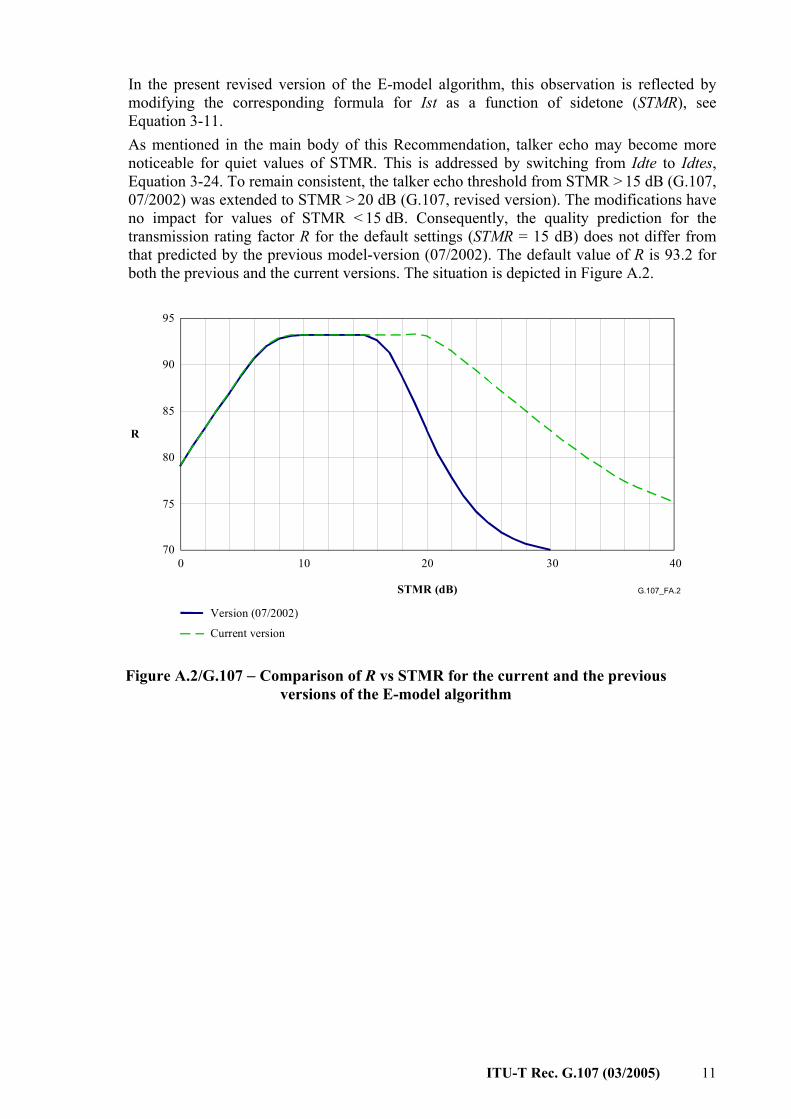
In the present revised version of the E-model algorithm, this observation is reflected by modifying the corresponding formula for Ist as a function of sidetone (STMR), see Equation 3-11.
As mentioned in the main body of this Recommendation, talker echo may become more noticeable for quiet values of STMR. This is addressed by switching from Idte to Idtes, Equation 3-24. To remain consistent, the talker echo threshold from STMR > 15 dB (G.107, 07/2002) was extended to STMR > 20 dB (G.107, revised version). The modifications have no impact for values of STMR < 15 dB. Consequently, the quality prediction for the transmission rating factor R for the default settings (STMR = 15 dB) does not differ from that predicted by the previous model-version (07/2002). The default value of R is 93.2 for both the previous and the current versions. The situation is depicted in Figure A.2.
G.107_FA.2
70
75
80
85
90
95
0 10 20 30
STMR (dB)
R
Version (07/2002)
Current version
40
Figure A.2/G.107 − Comparison of R vs STMR for the current and the previous versions of the E-model algorithm

12 ITU-T Rec. G.107 (03/2005)
Annex B
Quality measures derived from the transmission rating factor R
The transmission rating factor R can lie in the range from 0 to 100, where R = 0 represents an extremely bad quality and R = 100 represents a very high quality. The E-model provides a statistical estimation of quality measures. The percentages for a judgement Good or Better (GoB) or Poor or Worse (PoW) are obtained from the R-factor by means of the Gaussian Error function:
∫∞π
=x t
dtxE–
2–
2
e21)( (B-1)
The equations are:
%16
60–100
= REGoB (B-2)
%16–45100
= REPoW (B-3)
An estimated Mean Opinion Score (MOSCQE) for the conversational situation in the scale 1-5 can be obtained from the R-factor using the formulae:
For R < 0: 1MOSCQE =
For 0 < R < 100: 6CQE 107)100)(60(035.01MOS −⋅−−++= RRRR (B-4)
For R > 100: 5.4MOSCQE =
This formula can be inverted in the range 1005.6 ≤≤ R to calculate R from MOSCQE, see Appendix I. GoB, PoW and MOSCQE as functions of R are depicted in Figures B.1 and B.2 respectively.
G.107_FB.1
PoW GoB
9998
9590
80706050403020
105
21
0 20 40 60 80 100 R
%
Figure B.1/G.107 – GoB (Good or Better) and PoW (Poor or Worse) as functions of rating factor R

ITU-T Rec. G.107 (03/2005) 13
G.107_FB.2
Excellent 5
Good 4
Fair 3
Poor 2
Bad 10 20 40 60 80 100 R
MOS
Figure B.2/G.107 – MOSCQE as function of rating factor R
In some cases, transmission planners may not be familiar with the use of quality measures such as the R rating factor obtained from planning calculations, and thus provisional guidance for interpreting calculated R factors for planning purposes is given in Table B.13. This table also contains equivalent transformed values of R into estimated conversational MOSCQE, GoB and PoW.
Table B.1/G.107 – Provisional guide for the relation between R-value and user satisfaction
R-value (lower limit)
MOSCQE (lower limit)
GoB (%) (lower limit)
PoW (%) (upper limit)
User satisfaction
90 4.34 97 ∼0 Very satisfied
80 4.03 89 ∼0 Satisfied
70 3.60 73 6 Some users dissatisfied 60 3.10 50 17 Many users dissatisfied 50 2.58 27 38 Nearly all users dissatisfied
____________________ 3 The source of Table B.1 is Table 1/G.109 [3].

14 ITU-T Rec. G.107 (03/2005)
Annex C
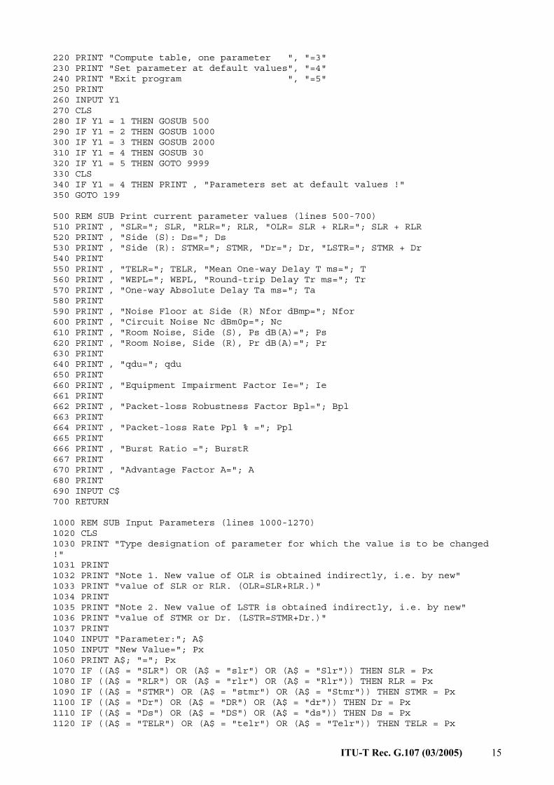
Source code for G.107_5 in BASIC 1 CLS 2 PRINT "PROGRAM g107_4" 3 REM THIS VERSION IS CONFORM WITH THE ALGORITHM 4 REM DESCRIBED IN REC. G.107 5 REM PROGRAM WRITTEN BY N.O. JOHANNESSON 6 REM MODIFIED BY S. MOELLER, 1999; A. RAAKE, 2003, 2005 7 PRINT 8 PRINT "E-model, algorithm according to ITU-T Rec. G.107 (2003) Annex C," 9 PRINT "for voice communication between side (S) and (R)." 10 PRINT 11 PRINT "The E-model gives an estimation of voice transmission quality" 12 PRINT "mouth-to-ear as perceived at Side (R). The model output is a" 13 PRINT "transmission rating factor R which can be transformed to give" 14 PRINT "estimates of customer opinion. Such estimates are only made for" 15 PRINT "transmission planning purposes and not for actual customer" 16 PRINT "opinion prediction. See ITU-T Rec. G.107 (2003) for more details." 17 PRINT 18 PRINT "Note: To continue program:" 19 PRINT "a) INPUT appropriate value as indicated on screen," 20 PRINT "or" 21 PRINT "b) if no value is asked for, PRESS THE RETURN KEY." 22 PRINT 23 DIM X(100), Y(5, 100), Col(5), Pxo(5) 24 REM Set parameters at default values 25 GOSUB 29 26 REM Goto main menu 27 GOTO 199 29 REM Default Parameter Values, according to Tab.3/G.107 (lines 29-60) 30 SLR = 8 31 RLR = 2 32 STMRs = 15 33 Ds = 3 34 STMR = 15 35 Dr = 3 36 LSTRr = 18 37 TELR = 65 38 T = 0 39 WEPL = 110 40 Tr = 0 41 Ta = 0 42 Ie = 0 43 Bpl = 1 44 Ppl = 0 45 BurstR = 1 46 A = 0 47 Nc = -70 48 Ps = 35 49 Pr = 35 50 qdu = 1 55 Nfor = -64 60 RETURN 198 REM Main menu (lines 198-370) 199 PRINT 200 PRINT "Print current parameter values ", "=1" 210 PRINT "Input new parameter values ", "=2"
ITU-T Rec. G.107 (03/2005) 15
220 PRINT "Compute table, one parameter ", "=3" 230 PRINT "Set parameter at default values", "=4" 240 PRINT "Exit program ", "=5" 250 PRINT 260 INPUT Y1 270 CLS 280 IF Y1 = 1 THEN GOSUB 500 290 IF Y1 = 2 THEN GOSUB 1000 300 IF Y1 = 3 THEN GOSUB 2000 310 IF Y1 = 4 THEN GOSUB 30 320 IF Y1 = 5 THEN GOTO 9999 330 CLS 340 IF Y1 = 4 THEN PRINT , "Parameters set at default values !" 350 GOTO 199 500 REM SUB Print current parameter values (lines 500-700) 510 PRINT , "SLR="; SLR, "RLR="; RLR, "OLR= SLR + RLR="; SLR + RLR 520 PRINT , "Side (S): Ds="; Ds 530 PRINT , "Side (R): STMR="; STMR, "Dr="; Dr, "LSTR="; STMR + Dr 540 PRINT 550 PRINT , "TELR="; TELR, "Mean One-way Delay T ms="; T 560 PRINT , "WEPL="; WEPL, "Round-trip Delay Tr ms="; Tr 570 PRINT , "One-way Absolute Delay Ta ms="; Ta 580 PRINT 590 PRINT , "Noise Floor at Side (R) Nfor dBmp="; Nfor 600 PRINT , "Circuit Noise Nc dBm0p="; Nc 610 PRINT , "Room Noise, Side (S), Ps dB(A)="; Ps 620 PRINT , "Room Noise, Side (R), Pr dB(A)="; Pr 630 PRINT 640 PRINT , "qdu="; qdu 650 PRINT 660 PRINT , "Equipment Impairment Factor Ie="; Ie 661 PRINT 662 PRINT , "Packet-loss Robustness Factor Bpl="; Bpl 663 PRINT 664 PRINT , "Packet-loss Rate Ppl % ="; Ppl 665 PRINT 666 PRINT , "Burst Ratio ="; BurstR 667 PRINT 670 PRINT , "Advantage Factor A="; A 680 PRINT 690 INPUT C$ 700 RETURN 1000 REM SUB Input Parameters (lines 1000-1270) 1020 CLS 1030 PRINT "Type designation of parameter for which the value is to be changed !" 1031 PRINT 1032 PRINT "Note 1. New value of OLR is obtained indirectly, i.e. by new" 1033 PRINT "value of SLR or RLR. (OLR=SLR+RLR.)" 1034 PRINT 1035 PRINT "Note 2. New value of LSTR is obtained indirectly, i.e. by new" 1036 PRINT "value of STMR or Dr. (LSTR=STMR+Dr.)" 1037 PRINT 1040 INPUT "Parameter:"; A$ 1050 INPUT "New Value="; Px 1060 PRINT A$; "="; Px 1070 IF ((A$ = "SLR") OR (A$ = "slr") OR (A$ = "Slr")) THEN SLR = Px 1080 IF ((A$ = "RLR") OR (A$ = "rlr") OR (A$ = "Rlr")) THEN RLR = Px 1090 IF ((A$ = "STMR") OR (A$ = "stmr") OR (A$ = "Stmr")) THEN STMR = Px 1100 IF ((A$ = "Dr") OR (A$ = "DR") OR (A$ = "dr")) THEN Dr = Px 1110 IF ((A$ = "Ds") OR (A$ = "DS") OR (A$ = "ds")) THEN Ds = Px 1120 IF ((A$ = "TELR") OR (A$ = "telr") OR (A$ = "Telr")) THEN TELR = Px

16 ITU-T Rec. G.107 (03/2005)
1130 IF ((A$ = "T") OR (A$ = "t")) THEN T = Px 1140 IF ((A$ = "WEPL") OR (A$ = "wepl") OR (A$ = "Wepl")) THEN WEPL = Px 1150 IF ((A$ = "Tr") OR (A$ = "TR") OR (A$ = "tr")) THEN Tr = Px 1160 IF ((A$ = "Ta") OR (A$ = "TA") OR (A$ = "ta")) THEN Ta = Px 1170 IF ((A$ = "Ie") OR (A$ = "IE") OR (A$ = "ie")) THEN Ie = Px 1171 IF ((A$ = "Bpl") OR (A$ = "BPL") OR (A$ = "bpl")) THEN Bpl = Px 1172 IF ((A$ = "Ppl") OR (A$ = "PPL") OR (A$ = "ppl")) THEN Ppl = Px 1173 IF ((A$ = "BurstR") OR (A$ = "BURSTR") OR (A$ = "burstr")) THEN BurstR = Px 1180 IF ((A$ = "A") OR (A$ = "a")) THEN A = Px 1190 IF ((A$ = "Nc") OR (A$ = "NC") OR (A$ = "nc")) THEN Nc = Px 1200 IF ((A$ = "Ps") OR (A$ = "PS") OR (A$ = "ps")) THEN Ps = Px 1210 IF ((A$ = "Pr") OR (A$ = "PR") OR (A$ = "pr")) THEN Pr = Px 1220 IF ((A$ = "qdu") OR (A$ = "QDU") OR (A$ = "Qdu")) THEN qdu = Px 1230 IF ((A$ = "Nfor") OR (A$ = "NFOR") OR (A$ = "nfor")) THEN Nfor = Px 1240 PRINT 1250 IF Y1 = 2 THEN INPUT "More parameters changed, Yes(1) or No(0)"; Ypar 1260 IF Ypar = 1 THEN GOTO 1020 1270 RETURN 2000 REM SUB Tabulate (lines 2000-3000) 2020 INPUT "Variable Parameter:"; A$ 2030 PRINT "(To exit tabulation, put parameter value = 1000 !)" 2040 PRINT TAB(8); A$; TAB(18); "R"; TAB(28); "GOB %"; TAB(38); "POW %"; TAB(48); "MOS" 2050 INPUT Px 2060 IF Px = 1000 THEN GOTO 3000 2070 IF ((A$ = "SLR") OR (A$ = "slr") OR (A$ = "Slr")) THEN SLR = Px 2080 IF ((A$ = "RLR") OR (A$ = "rlr") OR (A$ = "Rlr")) THEN RLR = Px 2090 IF ((A$ = "STMR") OR (A$ = "stmr") OR (A$ = "Stmr")) THEN 2100 STMR = Px 2110 LSTR = STMR + Dr 2120 END IF 2130 IF ((A$ = "Dr") OR (A$ = "DR") OR (A$ = "dr")) THEN 2140 Dr = Px 2150 LSTR = STMR + Dr 2160 END IF 2170 IF ((A$ = "TELR") OR (A$ = "telr") OR (A$ = "Telr")) THEN TELR = Px 2180 IF ((A$ = "T") OR (A$ = "t")) THEN T = Px 2190 IF ((A$ = "WEPL") OR (A$ = "wepl") OR (A$ = "Wepl")) THEN WEPL = Px 2200 IF ((A$ = "Tr") OR (A$ = "TR") OR (A$ = "tr")) THEN Tr = Px 2210 IF ((A$ = "Ta") OR (A$ = "TA") OR (A$ = "ta")) THEN Ta = Px 2220 IF ((A$ = "Ie") OR (A$ = "IE") OR (A$ = "ie")) THEN Ie = Px 2221 IF ((A$ = "Bpl") OR (A$ = "BPL") OR (A$ = "bpl")) THEN Bpl = Px 2222 IF ((A$ = "Ppl") OR (A$ = "PPL") OR (A$ = "ppl")) THEN Ppl = Px 2223 IF ((A$ = "BurstR") OR (A$ = "BURSTR") OR (A$ = "burstr")) THEN BurstR = Px 2230 IF ((A$ = "A") OR (A$ = "a")) THEN A = Px 2240 IF ((A$ = "Nc") OR (A$ = "NC") OR (A$ = "nc")) THEN Nc = Px 2245 IF ((A$ = "Nfor") OR (A$ = "NFOR") OR (A$ = "nfor")) THEN Nfor = Px 2250 IF ((A$ = "Ps") OR (A$ = "PS") OR (A$ = "ps")) THEN Ps = Px 2260 IF ((A$ = "Pr") OR (A$ = "PR") OR (A$ = "pr")) THEN Pr = Px 2270 IF ((A$ = "qdu") OR (A$ = "QDU") OR (A$ = "Qdu")) THEN qdu = Px 2280 IF ((A$ = "Ie") OR (A$ = "IE") OR (A$ = "ie")) THEN Ie = Px 2290 IF ((A$ = "Ds") OR (A$ = "DS") OR (A$ = "ds")) THEN Ds = Px 2300 GOSUB 3500 2400 GOSUB 4000 2500 GOSUB 4100 2600 GOSUB 4200 2700 R = INT(R * 10 + .5) / 10 2800 PRINT TAB(8); Px; TAB(18); R; TAB(28); GOB; TAB(38); POW; TAB(48); MOS 2900 GOTO 2050 3000 RETURN 3500 REM Compute R (lines 3500-3880)

ITU-T Rec. G.107 (03/2005) 17
3509 REM Noise Summation, formulas (3) to (7) 3510 Nr1 = Ps – SLR – Ds – 100 3520 Nr1 = Nr1 + .004 * (Ps – SLR – RLR – Ds – 14) ^ 2 3530 LSTR = STMR + Dr 3540 Pro = Pr + 10 * LOG(1 + 10 ^ ((10 – LSTR) / 10)) / LOG(10) 3550 Pr1 = Pro + .008 * (Pro – 35) ^ 2 3560 Nr2 = Pr1 – 121 + RLR 3570 Nfo = Nfor + RLR 3580 No = 10 * LOG(10 ^ (Nr1 / 10) + 10 ^ (Nr2 / 10) + 10 ^ (Nc / 10) + 10 ^ (Nfo / 10)) / LOG(10) 3590 Nt = No – RLR 3599 REM Ro, formula (2) 3600 Ro = 15 – 1.5 * (SLR + No) 3609 REM Iolr, formulas (9) and (10) 3610 Xolr = SLR + RLR + .2 * (64 + Nt) 3620 Iolr = 20 * ((1 + (Xolr / 8) ^ 8) ^ (1 / 8) – Xolr / 8) 3629 REM Ist, formulas (11) and (12) 3630 STMRo = -10 * LOG(10 ^ (-STMR / 10) + 10 ^ (-TELR / 10) * EXP(-T / 4)) / LOG(10) 3640 Ist = 12 * (1 + ((STMRo – 13) / 6) ^ 8) ^ (1 / 8) 3645 Ist = Ist – 28 * (1 + ((STMRo + 1) / 19.4) ^ 35) ^ (1 / 35) 3650 Ist = Ist – 13 * (1 + ((STMRo – 3) / 33) ^ 13) ^ (1 / 13) + 29 3659 REM Iq, formulas (13) to (17) 3660 IF qdu < 1 THEN qdu = 1 3670 Q = 37 – 15 * LOG(qdu) / LOG(10) 3680 G = 1.07 + .258 * Q + .0602 * Q ^ 2 3690 Iq = 15 * LOG(1 + 10 ^ ((Ro – 100) / 15) * 10 ^ (46 / 8.4 – G / 9) + 10 ^ (46 / 30 – G / 40)) / LOG(10) 3699 REM Is, formula (8) 3700 Isyn = Iolr + Ist + Iq 3709 REM TERV, formula (22) 3710 TERV = TELR + 6 * EXP(-.3 * T ^ 2) – 40 * LOG((1 + T / 10) / (1 + T / 150)) / LOG(10) 3719 REM Modifications to satisfy formula (23) 3720 IF STMR < 9 THEN TERV = TERV + .5 * Ist 3729 REM Idte, formulas (19) to (21) 3730 Re = 80 + 2.5 * (TERV – 14) 3740 Roe = -1.5 * (No – RLR) 3750 Xdt = (Roe – Re) / 2 3760 Idte = Xdt + SQR(Xdt ^ 2 + 100) 3770 Idte = (Idte – 1) * (1 – EXP(-T)) 3779 REM Modifications to satisfy formula (24) 3780 IF STMR > 20 THEN Idte = SQR(Idte ^ 2 + Ist ^ 2) 3789 REM Idle, formulas (25) and (26) 3790 Rle = 10.5 * (WEPL + 7) * (Tr + 1) ^ (-1 / 4) 3800 Xdl = (Ro – Rle) / 2 3810 Idle = Xdl + SQR(Xdl ^ 2 + 169) 3819 REM Idd, formulas (27) and (28) 3820 IF Ta < 100 THEN Idd = 0 3830 IF Ta = 100 THEN Idd = 0 3840 IF Ta > 100 THEN X = (LOG(Ta / 100)) / LOG(2) Idd = 25 * ((1 + X ^ 6) ^ (1 / 6) – 3 * (1 + (X / 3) ^ 6) ^ (1 / 6) + 2) 3850 END IF

18 ITU-T Rec. G.107 (03/2005)
3859 REM Id 3860 Id = Idte + Idle + Idd 3864 REM Inclusion of packet-loss: Ieef, formula (29) 3865 Ieef = Ie + (95 - Ie) * (Ppl / ((Ppl / BurstR) + Bpl)) 3869 REM R, formula (1) 3870 R = Ro – Isyn – Id – Ieef + A 3880 RETURN 4000 REM Compute GOB, formula (B.2) (lines 4000-4050) 4010 Z# = (R – 60) / 16 4020 GOSUB 5000 4030 GOB = 100 * F# 4040 GOB = INT(GOB * 10 + .5) / 10 4050 RETURN 4100 REM Compute POW, formula (B.3) (lines 4100-4150) 4110 Z# = (R – 45) / 16 4120 GOSUB 5000 4130 POW = 100 * (1 – F#) 4140 POW = INT(POW * 10 + .5) / 10 4150 RETURN 4200 REM Compute MOS, formula (B.4) (lines 4200-4260) 4210 MOS = 1 + R * .035 + R * (R – 60) * (100 – R) * 7 * 10 ^ (-6) 4220 MOS = INT(MOS * 100 + .5) / 100 4230 IF R < 0 THEN MOS = 1 4240 IF MOS < 1 THEN MOS = 1 4250 IF R > 100 THEN MOS = 4.5 4260 RETURN 5000 REM Norm Distr F(Z), formula (B.1) (lines 5000-5130) 5010 S# = 0 5020 N% = 0 5030 H# = Z# 5040 S# = S# + H# 5050 H# = H# * (-1) * (Z#) ^ 2 * (2 * N% + 1) / ((N% + 1) * 2 * (2 * N% + 3)) 5060 N% = N% + 1 5070 IF ABS(H#) < 10 ^ (-6) THEN GOTO 5090 5080 GOTO 5040 5090 S# = S# / (SQR(2 * 3.14159265#)) 5100 F# = .5 + S# 5110 F# = INT(F# * 10 ^ 5 + .5) / 10 ^ 5 5120 REM PRINT "Z="; Z#, "F(Z)="; F#, "N="; N% 5130 RETURN 9999 END

ITU-T Rec. G.107 (03/2005) 19
Appendix I
Calculation of R from MOSCQE values
In the range 1005.6 ≤≤ R , R can be calculated from MOSCQE using the formula:
+−=
3πcos2268
320 hR (I-1)
with:
−+−−= 2
31 202500111396090352215,675018566 arctan2 CQECQECQE MOSMOSMOSh (I-2)
and:
( )
<
−−
≥
=0forarctanπ
0forarctan arctan2
xx
y
xxy
x,y (I-3)
The function arctan2(x, y) is implemented in ANSI C as the function atan2(y, x). Users should note that the order of the two parameters differs in this case.

20 ITU-T Rec. G.107 (03/2005)
BIBLIOGRAPHY
– ITU-T Recommendation G.107 (1998), The E-model, a computational model for use in transmission planning.
– ITU-T Recommendation G.107 (2000), The E-model, a computational model for use in transmission planning.
– ITU-T Recommendation G.107 (2002), The E-model, a computational model for use in transmission planning.
– ITU-T P-series Recommendations – Supplement 3 (1993), Models for predicting transmission quality from objective measurements.


Printed in Switzerland Geneva, 2005
SERIES OF ITU-T RECOMMENDATIONS
Series A Organization of the work of ITU-T
Series D General tariff principles
Series E Overall network operation, telephone service, service operation and human factors
Series F Non-telephone telecommunication services
Series G Transmission systems and media, digital systems and networks
Series H Audiovisual and multimedia systems
Series I Integrated services digital network
Series J Cable networks and transmission of television, sound programme and other multimedia signals
Series K Protection against interference
Series L Construction, installation and protection of cables and other elements of outside plant
Series M Telecommunication management, including TMN and network maintenance
Series N Maintenance: international sound programme and television transmission circuits
Series O Specifications of measuring equipment
Series P Telephone transmission quality, telephone installations, local line networks
Series Q Switching and signalling
Series R Telegraph transmission
Series S Telegraph services terminal equipment
Series T Terminals for telematic services
Series U Telegraph switching
Series V Data communication over the telephone network
Series X Data networks, open system communications and security
Series Y Global information infrastructure, Internet protocol aspects and next-generation networks
Series Z Languages and general software aspects for telecommunication systems