iv. orthorhombic system · of the orthorhombic system are characterized by three axes of binary...
TRANSCRIPT
ORTHORHOMBIC SYSTEM 121
The indires of each face are obtained directly by taking these intercepts upon the three horizontal axes in their proper order and by adding a 1 as the fourth figure. If necessary clear of fractions, as in the case of the second order pyramid, 1122.
173. To determine the axial ratio of a hexagonal mineral from the gnomonic pro'ection of its forms. The gnomonic projection of the beryl forms, Fig. 295, may be used as an illustrative example. The radius of the fundamental circle, a, is taken as equal to the length of thc horizontal axes and is given a value of 1. Then the length of the funda- mer,,al intercept of the lines dropped perpendicularly from the les, i.e. the distance c, will equal the length of the c axis when expremed in terms of t h e g n e h of a. In the case of beryl this ratio is a : c = 1'00 : 0'499. That this relationship is true can be proved in the same manner a? in the case of the tetragonal eystem, see Art. 117, p. 93.
IV. ORTHORHOMBIC SYSTEM (Rhombic or Prismatic System)
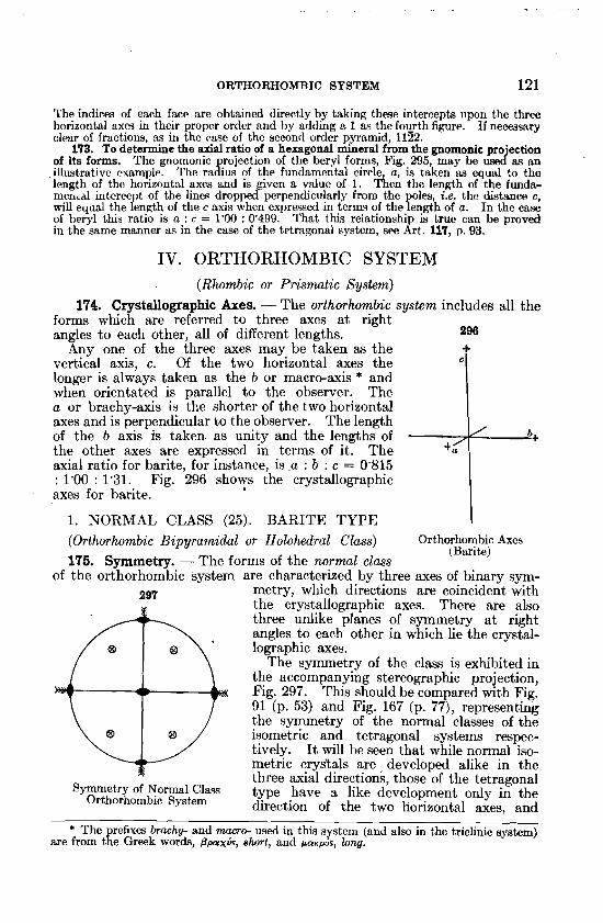
174. Crystallographic Axes. - The orthmhombic system includes all the forms which are referred to three axes at right angles to each other, all of different lengths. 296
Any one of the three axes may be taken as the vertical axis, c. Of the two horizontal axes the longer is always taken as the b or macro-axis * and when orientated is parallel to the observer. The a or brachy-axis is the shorter of the two horizontal axes and is perpendicular to the observer. The length of the b axis is taken as unity and the lengths of the other axes are expressed in terms of it. The axial ratio for barite, for instance, is a : b : c = 0'815 : 1 0 : 1 3 1 . Fig. 296 shows the crystallographic axes for barite.
1. NORMAL CLASS (25). BARITE TYPE (Orthorhombic Bipyramidal or Holohedral Class) Orthorhombic Axes
(Barite) 175. Symmetry. - The forms of the normal class
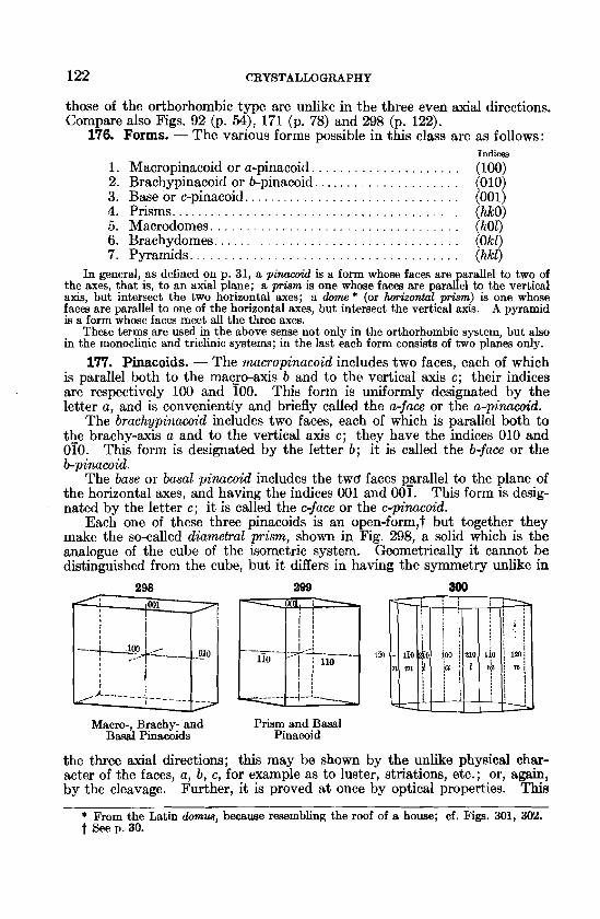
of the orthorhombic system are characterized by three axes of binary sym- 297 metry, which directions are coincident with
the crystallographic axes. There are also three unlike planes of symmetry a t right angles to each other in which lie the crystal- lographic axes.
The symmetry of the class is exhibited in the accompanying stereographic projection, Fig. 297. This should be compared with Fig. 91 (p. 53) and Fig. 167 (p. 77) , representing the symmetry of the normal classes of the isometric and tetragonal systems respec- tively. It will be seen that while normal iso- metric crystals are , developed alike in the three axial directions, those of the tetragonal
Symmetry of Normal Clasq type have a like development only in the Orthorhomhic System direction of the two horizontal axes, and
* The prefixes b~aehy- and mmo- used in this system (and also in the triclinic system) are from the Greek words, ppaxis, s h ~ t , and partPo's, long.
122 CRYSTALLOGRAPHY
those of the orthorhombic type are unlike in the three even axial directions. Compare also Figs. 92 (p. 5 9 , 171 (p. 78) and 298 (p. 122).
176. Forms. - The various forms possible in this class are as follows: Indices
1. Macropinacoid or a-pinacoid. . . . . . . . . . . . . . . . . . . . . (100) 2. Brachypinacoid or b-pinacoid. . . . . . . . . . . . . . . . . . . . . (010) 3. Base or c-pinacoid.. . . . . . . . . . . . . . . . . . . . . . . . . . . . . . (001) 4. Prisms.. . . . . . . . . . . . . . . . . . . . . . . . . . . . . . . . . . . . . . . . (hkO) 5 . Macrodomes. . . . . . . . . . . . . . . . . . . . . . . . . . . . . . . . . . . (h01) 6. Brachydomes.. . . . . . . . . . . . . . . . . . . . . . . . . . . . . . . . . . (Okl) 7. Pyramids.. . . . . . . . . . . . . . . . . . . . . . . . . . . . . . . . . . . . . (hkl)
In general as defined on p. 31, a pinacoid is a form whose faces are arallel to two of the axes, thadis, to an axial plane; a prism is one whose faces are to the vertical axis, but intersect the two horizontal axes; a dome * (or horizontal prism) is one whose faces are parallel to one of the horizontal axes, but intersect the vertical axis. A pyramid is a form whose faces meet a11 the three axes.
These terms are used in the above sense not only in the orthorhombic system, but also in the monoclinic and triclinic systems; in the last each form consists of two planes only.
177. Pinacoids. - The n~acropinacoid includes two faces, each of which is parallel both to the maqo-axis b and to the vertical axis c; their indices are respectively 100 and 100. This form is uniformly designated by the letter a, and is conveniently and briefly called the a-face or the a-pinucoid.
The brach.ypinacoid includes two faces, each of which is parallel both to the brachy-axis a and to the vertical axis c; they have the indices 010 and 010. This form is designated by the letter b; it is called the b-face or the b-pinucoid.
The base or basal pinacoid includes the twd faces p_arallel to the plane of the horizontal axes, and having the indices 001 and 001. This form is desig- nated by the letter c; it is called the c-face or the c-pinacoid.
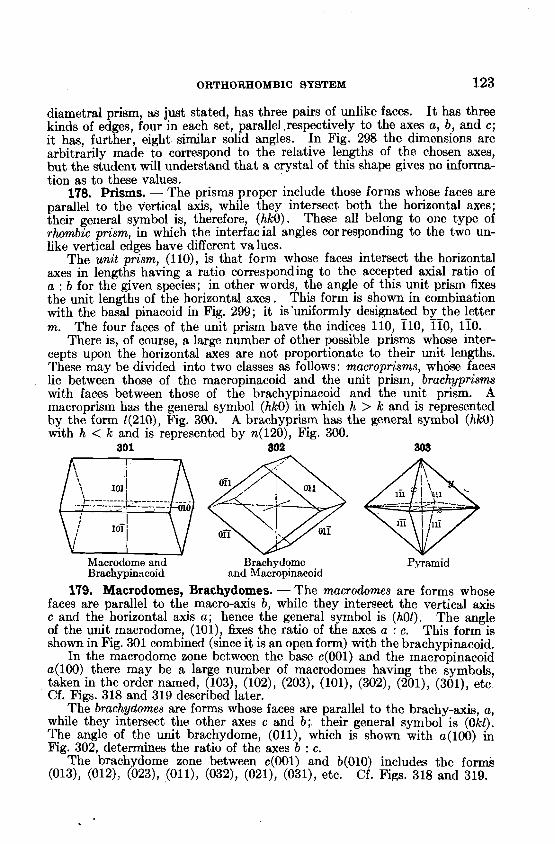
Each one of these three pinacoids is an open-form,t but together they make the so-called diametral prism, shown in Fig. 298, a solid which is the analogue of the cube of the isometric system. Geometrically it cannot be distinguished from the cube, but it differs in having the symmetry unlike in
298 209 800
Macro-, Brachy- and Prism and Basal B a d Pinacoids Pinacoid
the three axial directions; this may be shown by the unlike physical char- acter of the faces, a, b, c, for example as to luster, striations, etc.; or, again, by the cleavage. Further, it is proved at once by optical properties. This
From the Latin dmnua, because resembling the roof of a house; cf. Fip. 301, 302. t See p. 30.
ORTXORHOMBIC SYSTEM 123
diametral prism, as just stated, has three pairs of unlike faces. I t has three kinds of edges, four in each set, parallel.respective1y to the axes a, b, and c; it has, further, eight similar solid angles. In Fig. 298 the dimensions are arbitrarily made to correspond to the relative lengths of the chosen axes, but the student will understand that a crystal of this shape gives no informa- tion as to these values.
178. Prisms. - The prisms proper include those forms whose faces are parallel to the vertical axis, while they intersect both the horizontal axes; their general symbol is, therefore, (hkO). These all belong to one type of rhombic prism, in which the interfacial angles corresponding to the two un- like vertical edges have different values.
The unit prism, (110), is that form whose faces intersect the horizontal axes in lengths having a ratio corresponding to the accepted axial ratio of a : b for the given species; in other words, the angle of this unit prism fixes the unit lengths of the horizontal axes. This form is shown in combination with the basal pinacoid in Fig. 299 ; it is 'uniformly designated by the letter m. The four faces of the unit prism have the indices 110, 710, 770, 170.
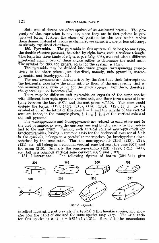
There is, of course, a large number of other possible prisms whose inter- cepts upon the horizontal axes are not proportionate to their unit lengths. These may be divided into two classes as follows: macroprisms, whose faces lie between those of the macropinacoid and the unit prism, brachyprisms wibh faces between those of the brachypinacoid and the unit prism. A macroprism has the general symbol (hkO) in which h > k and is represented by the form 1(210), Fig. 300. A brachyprism has the general symbol (hlcO) with h < k and is represented by n(120), Fig. 300.
301 302 303
Macrodome and Brnchydome Pyramid Brachypin:lcoid and Macropinncoid
179. Macrodomes, Brachydomes. - The macrodomes are forms whose faces are parallel to the macro-axis b, while they intersect the vertical axis c and the horizontal axis a ; hence the general symbol is (h01). The angle of the unit macrodome, (101), fixes the ratio of the axes a : c. This form is shown in Fig. 301 combined (since it is an open form) with the brachypinacoid.
In the macrodome zone between the base c(001) and the macropinacoid ~ (100) there may be a large number of macrodomes having the symbols, taken in the order named, (103), (102), (203), (101), (302), (201), (301): etc Cf. Figs. 318 and 319 described later.
The brachydomes are forms whose faces are parallel to the brachy-axis, a, while they intersect the other axes c and b; their general symbol is (Okl). The angle of the unit brachydome, (Oll), which is shown with ~ (100) in Fig. 302, determines the ratio of the axes b : c.
The brachydome zone between c(001) and b(010) includes the formk (013), (012): (023), (0111, (032), (021), (ON), etc. Cf. Figs. 318 and 319.
124 CRYSTALLOGRAPHY
Both sets of domes are often spoken of as horizontal prisms. The pro- priety of this expression is obvious, since they are in fact prisms in geo- metrical form; further, the choice of position for the axes which makes them domes, instead of prisms in the narrower sense, is more or less arbitrary, as already explained elsewhere.
180. Pyramids. - The pyramids in this system all belong to one type, the double rhombic pyramirl, bounded by eight faces, each a scalene triangle. This form has three kinds of edges, x, y, z (Fig. 303), each set with a different interfacial angle; two of these angles suffice to determine the axial ratio. The symbol for this, the general form for the system, is (hkl).
The pyramids may he divided into three groups corresponding respec- tively to the three prisms just described, namely, unit pyramids, macro- pyramids, and brachypyramids.
The unit pyramids are characterized by the fact that their intercepts on the horizontal axes have the same ratio as those of the unit prism; that is, the assumed axial ratio (a : b) for the given species. For them, therefore, the general symbol becomes (hhl).
There may be diffcrcnt unit pyramids on crystals of the same species with different intercepts upon the vertical axis, and these form a zone of faces lying between the base ~(001) and the unit prism m(110). This zone would include the forms, (119), ' (117), (115), (114)) (113), (112), (111). In the symbol of all of the forms of this zone h = k, and the lengths of the vertical axes are hence, in the example given, 8 , 3, +, 4, 4, 3 of the vertical axis c of the unit pyramid.
The macropyramids and brachypyranzids are related to each other and to the unit pyramids, as were the macroprisms and brachyprisms to themselves and to the unit prism. Further, each vertical zone of macropyramids (or brachypyramids), having a common ratio for the horizontal axes (or of h : Ic in the sy~nbol), belongs to a particular macroprism (or brachyprism) char- acterized by the same ratio. Thus the macropyramids (214), (213), (212), (421), etc., a11 belong in a common vertical zone between the base (001) and the prism (210). Similarly the brachypyrarnids (123), (122)) (121), (241), etc., fall in a common vertical zone between (001) and (120).
181. Illustrations. - The following figures of barite (304-311) give
Barite Crystals
excellent illustrations of crystals of a typical orthorhombic species, and show also how the habit of one and the same species may vary. The axial ratio for this species is a : b : c = 0'815 : 1 : 1'314. Here d is the macrodome
ORTHORHOMBIC SYSTEM 125
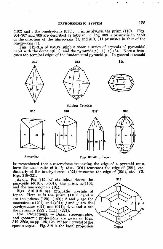
(102) and o the brachydome (011) ; ,m is, as always, the prism (110). Figs. 304-307 and 309 are described a.9 tabular i J c; Fig. 308 is prismatic in habit in the direction of the macro-axis ( b ) , and 310, 311 prismatic in that of the brachy-axis (a).
Figs. 312-314 of native sulphur show a series of crystals of pyraniidal habit with the dome n(011), and the pyramids p( l l l ) , ~(113). Note n trun- cates the terminal edges of the fundamental pyramid p. In general it should
Sulphur Crystah
318 817
Staurolite Figs. 316318, TOPRE
be remembered that a macrodome truncating the edge of a pyramid must have the same ratio of h : 1; thus, (201) truncates the edge of (221), etc. Similarly of the brachydomes: (021) truncates the edge of (221), etc. Cf. Figs. 319-321.
Again, Fig. 315, of staurolite, shows the 319 pinacoids b(010), ~ ( 0 0 1 ) ~ the prism m(l lo), and the macrodome ~(101).
Figs. 31G318 are prismatic crystals of topaz. Here m is the prism (110); 1 and n are the prisms (120), (140); d and p are the macrodomes (201) and (401) ; f and y are the brachydomes (021) and (041); i, u, and o are the pyramids (223), (1 1 I), (221).
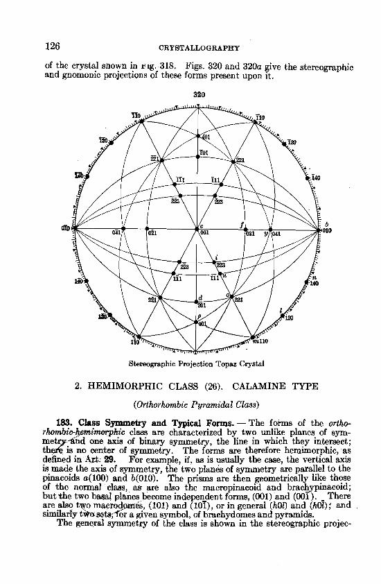
182. Projections. - Basal, stereographic, and gnomonic projections are given in Figs. 319-320a, on pp. 125,126,127 for a crystal of the species topaz. Fig. 319 is the basal projection Topaz
126 CRYSTALLOGRAPHY
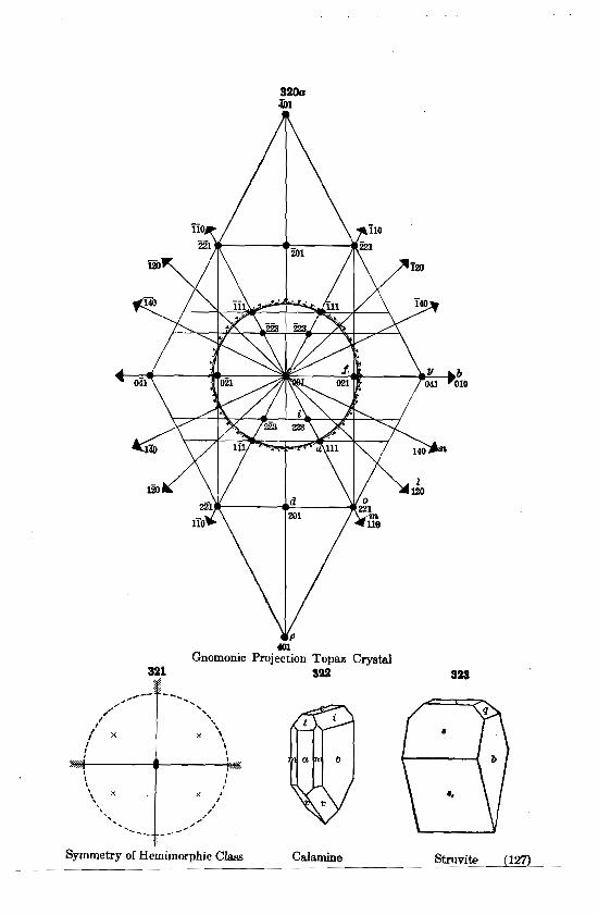
of the crystal shown in J! ig.318. Figs. 320 and 320a give the stereographic and gnomonic projections of these forms present upon it.
320
Stereographic Projection Topaz Crystal
2. HEMIMORPHIC CLASS (26). CALAMINE TYPE
(Orthorhmnbic Pyramidal Class)
183. Class Symmetry and Typical Forms. -The forms of the ortho- rhornbic-hemimqhic class are characterized by two unlike planes of sym-
T3 -dnd one axis of binary symmetry, the line in which they intersect; is no center of symmetry. The forms are bherefore hemimorphic, as
defined in A&: 29. For example, if, as is usually the case, the vertical axis is,made the axis of symmetry, the two planes of symmetry are parallel to the plnacoids a(100) and b(010). The prisms are then geometrically like those of the normal class, as are also the macropinacoid and bracbpinacold; but+the two basal planes become indepen_dent forms, (001) and (001). - There are also two macrocJwes, (101) and (101), or in general (h01) and (hot); and similarly t h s e t s ; for a given symbol, of brachydomes and pyramids.
The general symmetry of the class is shown in the stereographic projec-
4ol Gnomonic Projection Topaz Crystal
3% 399 sas
Symmetry of Hemimorphic Clam Calamine StruviC (127)
128 CRYSTALLOGRAPHY
tion, Fig. 321. Further, Figs. 322, of calamine, and 323, of struvite, represent typical crystals of this class. In Fig. 322-the forms present are t(301), i(031), v(121); in Fig. 323 they are ~ ( 1 0 1 ) ~ s1(101), q(011).
3. SPHENOIDAL CLASS (27). EPSOMITE TYPE.
(Orthorhombic Bisphenoiclul Class)
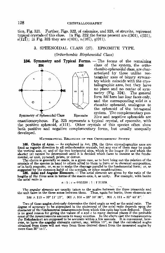
184. Symmetry and Typical Forms. - The forms of the remaining 524 836 class of the system, the ortho-
-- ----+-- --.-- rhombic-sphenoidal class, are char- 0 acterized by three unlike rec- , x i l.., tangular axes of binary symme- try which coincide with the crys-
i ;
tallographic axes, but they have 4 ---.-----------A -.-.------."-- +g w nz/
no plane and no center of sym-
'. ; metry (Fig. 324). The general
I ; I form hkl here has four faces only, ; :.. o i x ,<' ,---__ r and the corresponding solid is a
,," I ,,.' 5. ' rhombic sphenoid, analogous to -. the sphenoid of the tetragonal
system. The complementary pos- Symmetry of Sphenoidal Ch E ~ " m i t e itive and sDhenoids are
enantiornorphous. Fig. 325 represents a typical crystd, of ep'somite, with the positive sphenoid, ~(111). Other crystals of this species often show both positive and negative complementary forms, but usually unequally developed.
MATHEMATICAL RELATIONS OF THE ORTHORHOMBIC SYSTEM
186. Choice of Ares. - As explained in Art. 176, the three crystallographic axes are fixed as re ards direction in all orthorhombic crystals, but any one of them may be made the vertica? axis, e ; and of the two horizontal axes, which is the longer ( b ) and which the shorter ( a ) cannot be determined until it is decided which faces to assume as the funda- mental, or unit, pyramid, prism, or domes.
The choice is generally so made, in a given case, as to best bring out the relation of the crystal4 of the species in hand to others allied to them in form or in chemical composition, or in both respects; or, so as to make the cleavage parallel to the fundamental form; or, as su he common habit of the crystals, or other considerations.
and Angular Elements. - The azial elements are given by the ratio of the lengths of the three axes in term of the macro-axis, b, as unity. For example, with barite the axial ratio is
a : b : c = 0'81520 : 1 : 1'31359. L- --
The angular e h e n k are usually taken as the angles between the three-pinacoids and the unit faces in the three zonea between them. Thus, again for barite, these elements are
100 A 110 = 39" 11' 13", 001 A 101 = 58' 10' 36", 001 A 011 = 52" 43' 8". '
Two of these angles obviously determine the third angle as well as the axial ratio. The degree of accuracy to be attempted In the statement of the axial ratlo de ends upon the character of the fundsrnental measurements from which this ratio has been $educed. There is no good reason for giving the values of a and c to many decimal places if the probable error of the measurements amounts to many minutes. In the above case the measurements (by HeImhacker) are supposed to be accurate within a few seconds. It is convenient, how- ever, to have the angular elements correct, say, within lo", so that the calculated angles obtained from t h e y will not vary from those derived direct from the measured angles by more than 30" to 1 .
ORTHORHOMBIC SYSTEM 129
187. Calculation of the Axes. - The following simple relations (cf. Art. 48) connect the axes with the angular elements:
tan (100 A 110) = a, tan (001 A 011) = c , tan (001 A 101) =
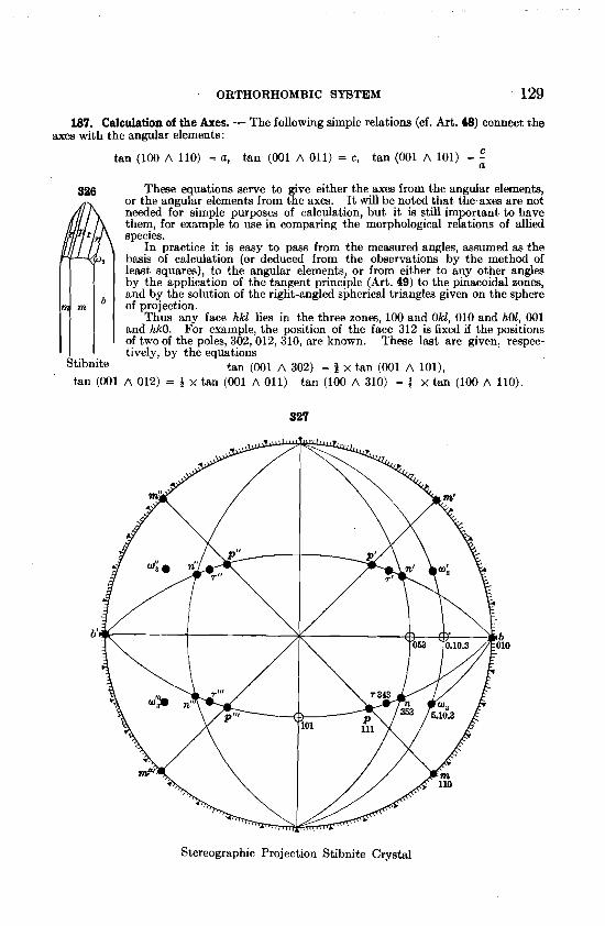
These equations serve to fve either the axes from the angular elements, 326 or the angular elements from t e axes. I t will be noted that the-axes are not needed for simple purposes of calculation, but it is still important to have them, for example to use in comparing the morphological relations of allied apecles.
In practice it is easy to pass from the measured angles, assumed as the basis of calculation (or deduced from the observations by the method of least squares), to the angular elements, or from either to any other angles by the application of the tangent principle (Art. 49) to the pinacoidal zones, and by the solution of the right-angled spherical triangles given on the sphere - - - - - of projection.
Thus any face hkl lies in the three zones, 100 and Okl, 010 and h01, 001 and hkO. For example, the position of the face 312 is fixed if the positions of two of the poles, 302,012, 310, are known. These last are given, respec- tively, by the equations
Stibnite tan (001 A 302) = 8 x tan (001 A 101), tan (001 A 012) = 4 x tan (001 A 011) tan (100 A 310) = j x tan (100 A 110).
Stereographic Projection Stibnite Crystal
130 CRYSTALLOGRAPHY
188. E-!!e. - Fig. 326 represents a crystal of stibnite from Japan and Fig. 327 the stermgrap IC ro'ection of its forms, p y l l ) , r(343), 1(353), u.(5'10'3), m ( l l 0 ) and b(010). On this t i e !allowing measured ang es were taken as fundamental:
1,)' (353 A 353) = 55" 1' O", 11"' (353 A 383) = 99" 39' 0".
Hence, the angles 353 A 010 = 40" 103' and 353 A 053 = 27' 304' are known with- out calculation. The right-angled s herical triangle * 010'053'353 yields the angle (010 A 053) and hence (001 A 053); ago the angle a t 010, which is equal to (001 A 101). But tan (001 A 011) = f x tan (001 A 053), and tan (001 A 011) = c . Also, since tan
(001 A 101) = c , thc axial ratio is thus known, and two of the angular elements.
The third angular element (001 A 110) can he calculated independently, for the angle at 001 in the triangle 001'053'353 is equal to (010 A 350) and tan (010 A 350) x J = (010 A 110), the complement of (100 A 110).
Then since tan (100 A 110) = a, this can be used to check the value of a already obtained. The further use of the tangent principle with the occasional solution of a right- angled triangle will serve to give any desired angle from either the fundamental angles direct, or from the an lar elements.
Again, the symboabf any unknown face can be readily calculated if two measured angles of tolerable accuracy are at hand. For example, for the face w , suppose the meas- ured angles to be
bo (010 A hkl) = 30" 15', ow' (hkl A h'kl) = 51" 32'
The solution of the triangle b'w'0kl gives the angle (010 A Okl) = 16" 25' 20", and
tan (001 A Okl) - tan 73" 34g - k tan (001 A 011) - tan 45" 303'
- 3'333+, = i.
But the ratio of k : 1 must be rational and the number derived agrees most closely with 10 : 3.
Again, the angle (001 A h01) may now be calculated from the same triangle and the value 59" 38f' obtained. From this the ratio of h to 1 is derived since
h tan (001 A h01) - tan 59" 388' = = - . tan (001 A 101) - tan 45' 43t' 1
This ratio is nearly equal to 5 : 3, and the two values thus obtained give the symbol 5'10'3. If, however, from the triangle 001' Okl'w, the angle a t 0 0 1 . i ~ calculated, the value 26" 42%' is obtained, which is also the angle (010 A hkO). From thls the ratio h : k is deduced, since
tan (010 A 110) - tan 45" 128' - - -- k tan (010 A hkO) tan 26" 423' = 2'002 =
'
k The value of - k hence closely equal to 2 ; thk combined with that first obtained (f = y ) h gives the same symbol 5'10'3.
This symbol being more than usually complex calls for fairly accurate memurements. How accurate the symbol obtained is can beat be judged by comparing the measured angles with those calculated from the symbol. For example, in the given case the calculated angles for ~ ( 5 ' 1 0 ' 3 ) are bw(010 A 5'10'3) = 30" 16', wo'(z'l0'3) = 51" 35'. The correctness of the value deduced is further established if it is found that the given face falls into prominent zones.
It will be understood further that the zonal relations, explained on pp. 4547, play an important part in all calculations. For exam le, in Fig. 326, if the symbol of T were un- known, it could be obtained from a single angg (as hr), since for this zone h = 1.
188. Formulas. - Although it is not often necessary to employ formulas in calculations, a few are added here for sake of completeness. Here a and c in the formulas are the lengths of the two axes a and c.
-- - -
* The student in this as in every similar case should draw a projection, cf. Fig. 327 (not necessarily accurately constructed), to show, if only approximately, the relative posi- tion of the faces present.
ORTHORHOMBIC SYSTEM 131
(1) For the distance between the pole of any face P(hk1) and the pinacoids a, b, c, we have in general:
h2c2 cosZ Pa = cos2 (hkl A 100) = h2 + k2a2C2 + 12a2 ;
kza2c2 cos2 Pb = cos2 (hkl A 010) = h2C2 + k2a2c2 + Pa2 ;
12a2 cos2 PC = cos2 (hkl A 001) = h2cZ + k2a2c2 + Z2a2 '
(2) For the distance (PQ) between the poles of any two faces (hkl) and (pqr) hpe2 + kqa2c2. + ha2 ~ - . cos PQ = 4[hzC2 + k2a2C2 + /2a2] [p2c2 + q2a2c2 + r2a21
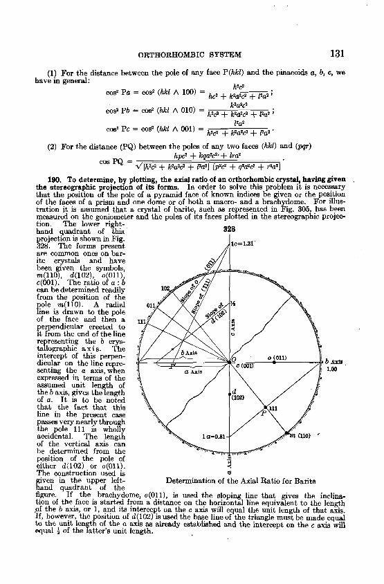
190. To determine, by plotting, the axial ratio of an orthorhombic crystal, havbg given . the stereographic projection of its forms. In order to solve h i s problem it is necessary that the position of the pole of a pyramid face of known indices be given or the position of the faces of a prism and one dome or of both a macro- and a brachydome. For illus- tration it is assumed that a crystal of barite, such as represented in Fig. 305, has been measured on the goniometer and the poles of ~ t s faces plotted in the stereogaphic projec- tion. The lower right- hand quadrant of this 328 projection is shown in Fig. 328. The forms present are common ones on bar- ite crystals and have been given the symbols, m(110), d(102),. o Oll), ~(001). The ratlo o ! a : b can be determined readily from the position of the pole m(110). A radial line is drawn to the pole of the face and then a 1 perpendicular erected to it from the end of the line representing the b crys- tallographic a x i s . The intercept of this perpen- dicular on the line repre- b 1 ~ 1 senting the a axis, when 1.00 expressed in terms of the assumed unit len h of T the b axis, gives the ength of a. I t is to be noted that the fact that this line in the present case passes very nearly through the pole 111 is wholl accidental. The lengtg of the vertical axis can be determined from the position of the pole of m
either d(102) or o(O1lj. The construction used is
3 u
given in the upper left- Determination of the Axial Ratio for Barite hand quadrant of the figure. If the brachydome, o(011), is used the sloping line that gives the inclina- tion of the face is started from a distance on the horizontal line equivalent to the length .of the b axis, or 1, and its intercept on the c axis will equal the unit length of that axis. If, however, the position of d(102) is used the base line of the triangle must be made equal to the unit len h of the a axis as already established and the intercept on the c &uis wiU equal ) of the E tter's unit length.
CRYSTALLOGRAPHY
The problem could have been wholly solved from the position of the pyramid face, 111, if that form had been present on the crystal. The construction in this case is also illustrated.
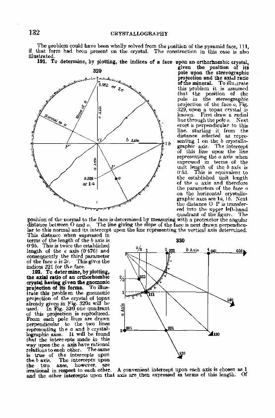
191. To determine, by plotting, the indices of a face upon an orthorhombic crystal,
329 given the position of irs pole upon the stereographic projection and the axial rano of the mineral. To illu,.crate this problem i t is assumed that the position of the pole in the stereographic projection of the face o, Fig. 329, upon a topaz crystal iq
known. First draw a radial line through the poleo. Next erect a perpendicular to this line, stnrtlng it from the distance selected as repre-
I senting 1 on the h crystallo- graphic axis. The intercept of this line upon the line representing the a axis when expressed in terms of the unit length of the b axis is 0'53. This is equivalent to
0.628 - the established unit length of the a axis and therefore the parameters of the face o on the horizontal crystallo- graphic axes are l a , l b . Next the distance 0-P is transfer- red into the upper left-hand quadrant of th-efigure The
sition of the normal to the face is determined b memuring with a protractor the angular E t a n c e between 0 and o. The line giving the s&pe of the face is next drawn perpendicu- lar to this normal and its interce~t uDon the line re~reaentine: the vertical axis determined. This distance when expressed ih
- - terms of the length of the b axis is 330 0'95. This is tw~ce the established length of the c axia (0'476) and consequently the third parameter of the face o is 2c. This gives the indices 221 for the face.
192. To determine, by plotting, the axial ratio of an orthorhombic z/3 crystal having gi vsn &a gnoqonic projection of its forms. To Illus- trate t h s problem the gnomonic 1 projection of the crystal of topaz already given in Fig. 320a will be , used. In Fig. 330 one quadrant of this projection. is reproduced. From each pole llnes are drawn perpendicular to the two lines representing t h e a and 6 cr stal lographic ares. it wiIl b e ibuni that the intercepts made m thrs way upon the a axis have rational relations to each other. The same is true of the intercepts upon the 6 axis. The intercepts upon the two axea, however, are irrational in respeot to each other. A convenient intercept upon each axis is chosen as 1 and the other intercepts upon that axis are-then expressed in terms of this length. Of
MONOCLINIC SYSTEM 133
course with a known mineral, whose forms have already had indices assigned to them, the intercept that shall be considered as 1 is fixed.
If we take r as equivalent to the radius of the fundamental circle of the projection, q as equal to the chosen intercept upon the b crystallographic axis and p that upon the a axk, then the axial ratio can be derived from the following expressions:
b - r ; - - c r = r _ . C q C P
The proof of these relationships is similar to that already given under the Tetragonal System, Art. 117, p. 93.
193. To determine, by plotting, the indices of a face upon an orthorhombic crystal, given the position of its pole upon the gnomonic projection and the axial ratio of the min- eral. The method of construction in this case is the reverse of that given in the problem above and is ementially the same as given under the Isometric and Tetra onal Systems, Arts. 84 and 118. In the case of an orthorhombic mineral the intercepts of t f e pe endicu- lam drawn from t,he pole of the face to the a and b axes must be expremed in eat% caae in terms of the unit intercept on that axis. These values, p and q, can be determined from the equations given in the preceding problem.
V. MONOCLINIC SYSTEM (Oblique System)
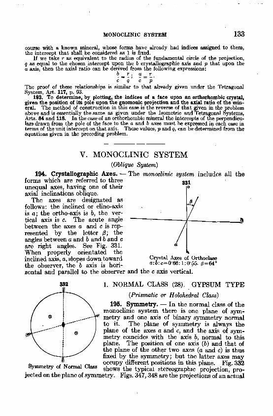
194. Crystallographic Axes. - The monoetinic system includes all the forms which are referred to three unequal axes, having one of their
331
axial inclinations oblique. The axes are designated as
follows : the inclined or clino-axis is a ; the ortho-axis is b, the ver- tical axis is c. The acute angle 4 between the axes a and c is r e p resented by the letter 0; the angles between a and b and b and c are right angles. See Fig. 331. a When properly orientated the 4 inclined axis, a, slopes down toward C stal Axes of Orthoclsee the observer, the b axis is hori- a3:c=0'66: 1 : o . s . @ = 6 4 O
zontal and parallel to the observer and the c axis vertical.
332 1. NORMAL CLASS (28). GYPSUM TYPE
(Prismatic or Holohedral Class) 196. Symmetry. - In the normal class of the
monoclinic system there is one plane of sym- metry and one axis of binary symmetry normal to it. The plane of symmetry is always the plane of the axes a and c, and the axis of sym- metry co~ncides with the axis b, normal to this plane. The position of one axis (b) and that of the plane of the other two axes (a and c) is thus fixed by the symmetry; but the latter axes may occupy different positions in this plane. Fig. 332
of Normal 'lass shows the typical stereographlc projection, pro- jected on the plane of symmetry. Figs. 347,348 are the projections of an actual