ivanpah solar thermal project acc1
TRANSCRIPT

0
Ivanpah Solar Thermal Project ACC

1
Ivanpah Organization
Solar Partners Holdco, LLC - Equity Investors NRG Google BrightSource
Three Individual Projects Solar Partners II – Ivanpah #1 - ~25 yr PPA with PG&E Solar Partners I – Ivanpah #2 - ~25 yr PPA with SCE Solar Partners VIII – Ivanpah #3 - ~25 yr PPA with PG&E
Southern California Edison Transmission Upgrade Implementing their El Dorado to Ivanpah Transmission Project

2
Environmental Considerations • Flora and fauna – Protected Species
Desert Tortoises Kit foxes Succulent Desert Plants Weed Management • Water - 100 acre-ft/year
2 on-site wells provide water
• Air – Emissions Title V GHS/cap and trade
• Avian/Bat - nesting and migratory birds Mortality surveys Scavenger surveys

3
Site Geography and Footprint
• Project site is 3500 acres
• Each unit about 900 acres
• Unit 1 to Unit 3 Tower = 3.2 miles
• Edge of U1 SF to edge of U3 SF = 5 miles
Tower
• Total Height is 459’
~325 ft steel structure w/ the boiler on top

4
Site Layout

5
Energy from Sun • Insolation is a measure of
solar radiation energy received on a given surface area and recorded during a given time.
• Direct insolation is the solar irradiance measured at a given location on Earth, excluding atmospheric diffused insolation.
• Solar radiation is absorbed & converted to thermal energy, causing an increase in the object's temperature.

6
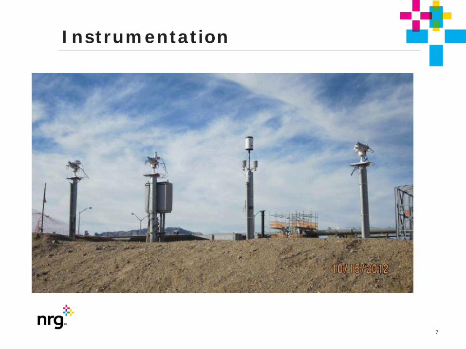
Weather Station Measurements Radiation Direct Normal Radiation (DNR) - Critical for optimizing performance Global Horizontal (GH) radiation Diffused Horizontal (DH) radiation UV horizontal radiation
Wind Wind speed in different locations - Critical for SF safety during high winds Wind direction
Ambient weather Ambient temperature Relative humidity Barometric pressure Rainfall
General Description
7
Instrumentation
8
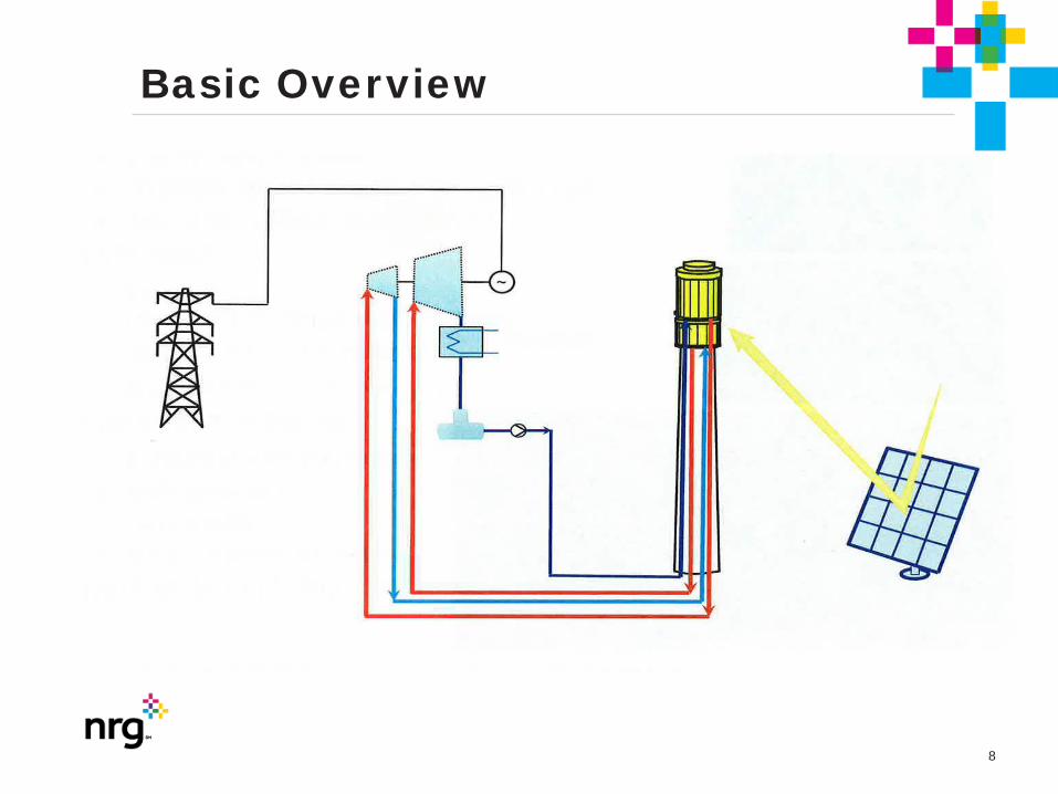
Basic Overview

9
Solar Field Control System (SFINCS) Heliostat desired aiming points calculating to: • Flux vs Load balancing • Implement quick flux reduction / defocusing • Measuring SRSG skin temperature • Alert on crossing temperature limits
10
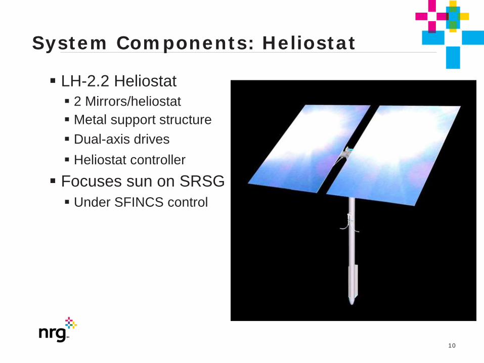
System Components: Heliostat
LH-2.2 Heliostat 2 Mirrors/heliostat
Metal support structure Dual-axis drives Heliostat controller Focuses sun on SRSG
Under SFINCS control
System Components: Heliostat

11
Solar Field
Mirror Focal lengths 4 different focal lengths were used in solar field
-250m -450m -750m -1000m
~60,000 heliostats per Unit

12

13
14
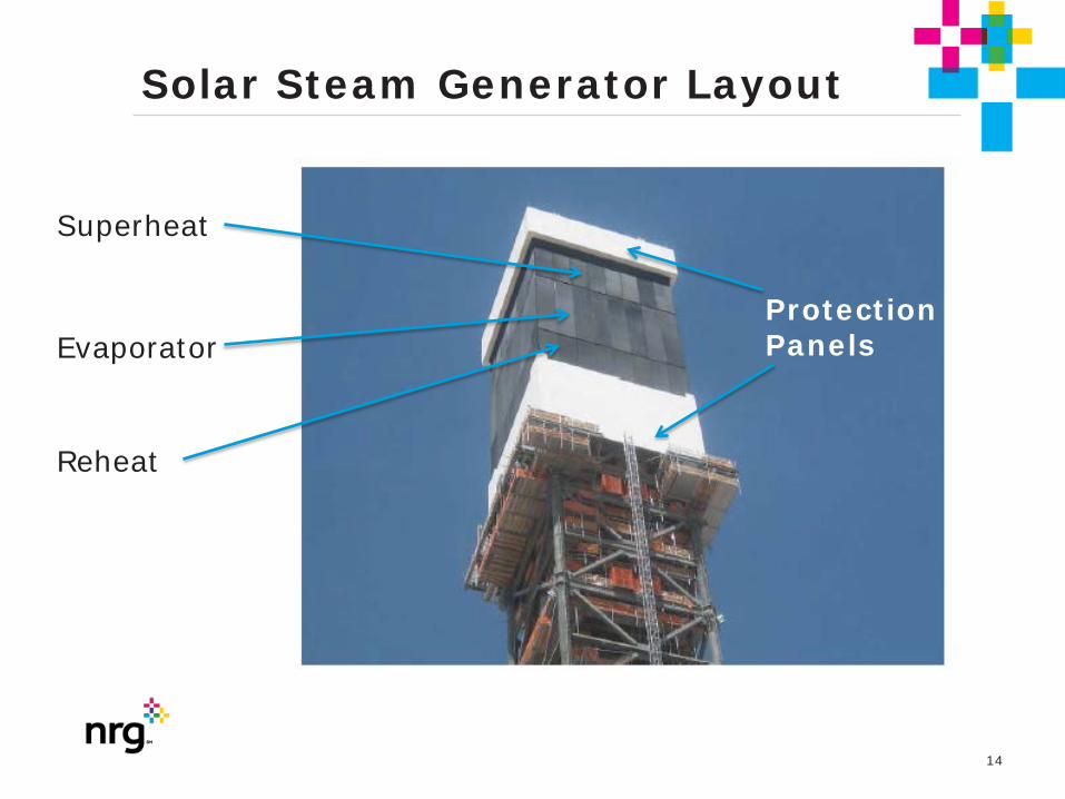
Solar Steam Generator Layout
Protection Panels
Superheat
Evaporator
Reheat

15
Water/Steam Overview

16
Power Block Configuration SOLAR RECEIVER STEAM
GENERATOR (RILEY POWER) Concentrated sunlight converts water in a boiler to high-temperature steam.
AIR-COOLED CONDENSER (SPX) Environmentally friendly in design, using 95% less water than competitive technologies.
HELIOSTATS (BRIGHTSOURCE) Software-controlled field of mirrors concentrate sunlight on a boiler mounted on a central tower.
OPTIMIZATION / CONTROL SOFTWARE (BRIGHTSOURCE) Solar Field Integrated Control System is the proprietary optimization software to manage heliostat positioning and optimize concentrated sunlight on the boiler.
TURBINE (SIEMENS) Steam powers turbine to produce electricity – then is converted back to water through an air-cooled condenser.

17
Power Block Layout

18
Air Cooled Condenser ACC-SPX
• Water Consumption limited to 100 acre-ft / year
• 3 Streets of 5 fans / Unit
• 2 Speed

NRG Energy, Inc. Confidential
OPERATING PARAMETERS ACC
Design Pressure Full Vacuum – 14.9 PSI Design Temperature 250ºF Back Pressure (BP)min 2 in Hga ACC Rupture Discs (3) 10.15 PSIG
Pressure Rating (30” Dia each) Combined Discharge Rate 1,407,329 LB/HR ACC Cooling Fans 2 Speed(s) 50 HP / 200 HP ACC Cooling Fan Gearbox Ratio 20.9:1 CCT Total Capacity 5,385 ft3 or 34,600 GALS
(12 minute storage capacity at maximum condensate flow of 825,552 lb/hr between normal level and low-low alarm)
Steam Duct Drain Pot Capacity 3602 GALS

20
Vibrational Assessment Jan 2014 • Upon startup, ACC fan were tested for vibration and it was
found that In late 2013, prior commissioning of the three Ivanpah Project Solar Power Generation units located in Primm, CA, the Air Cooled Condenser (ACC) had indicated a potential resonant frequency near blade pass frequency.
• 15 ACC fan cells, in 3x5 array, were installed on each of the units. The fans were designed with 9 blades, approximately 36 feet in diameter driven by two-speed (900 and 1790 rpm) induction motors (Marathon Electric Motors) through gear reducers (Hansen Industrial Gear Box) with a gear ratio of 20.9 to 1).
• Since the fans were designed with 9-blades, their typical strongest excitation occurs at blade-pass frequency (BPF) at 6.45 Hz – 12.85 Hz for low and high speeds, respectively.
• The ACC fans are not continuously monitored with vibration sensors, but vibration switches (1/4 way on the side of the bridge structure) have been installed to protect them from catastrophic failures. The trip setting of these vibration switches was 0.47 in/s RMS).

21
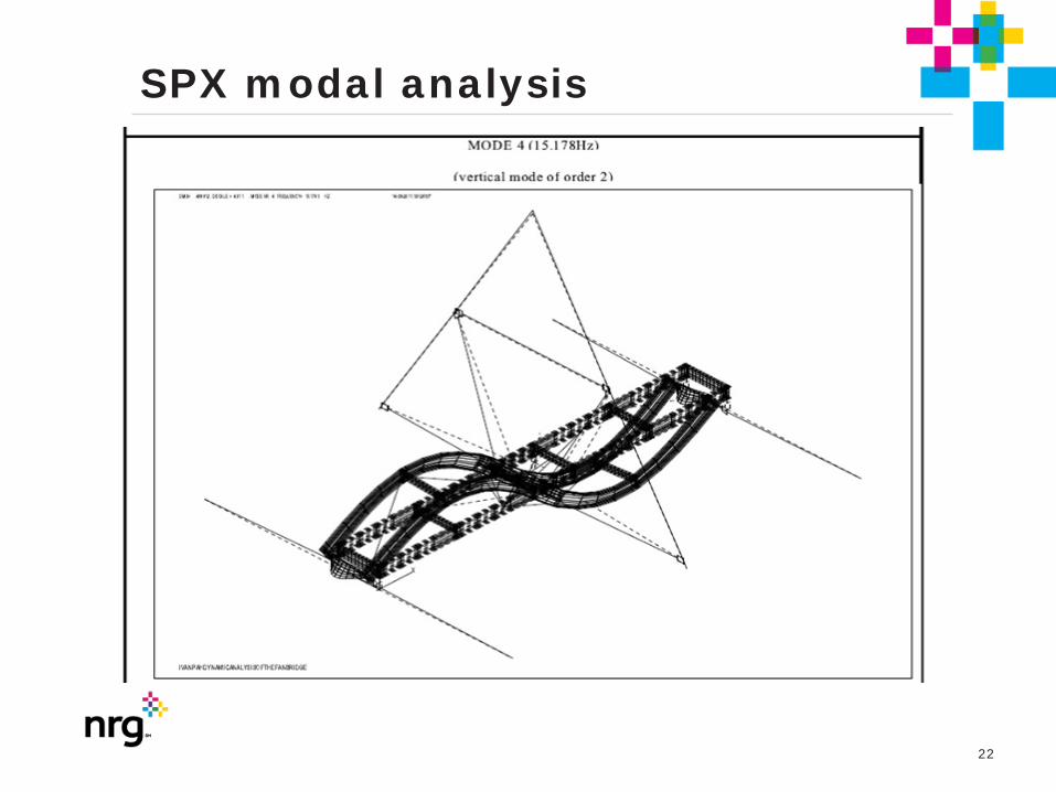
SPX modal analysis
22
SPX modal analysis

23
Site Photos

24
Observations • The elevated vibration amplitude of the motor/ gearbox
assembly mounted on the bridge system is due to a resonance of the lateral rocking mode of the motor /gearbox assembly (~13.1 Hz) in the parallel direction to the bridge. This mode is excited by Blade-Pass Frequency (BPF or 12.84 Hz) or nine times running speed of the shaft at full speed operation. This natural frequency was measured to be almost on top of the BPF with only 2% separation margin. Based on MSI’s experience, the minimum separation required is 10%, when it is measured in the field. FEA based prediction requires at least 15% of separation margin in order to take into account FEA’s assumptions and uncertainties.

25
Observations • Based on the Operating Deflection Shape (ODS) testing,
this offending structural natural frequency appears to be dominated by the flexibility of the I-beam support structure of the gearbox. The I-beam supporting the gearbox is twisting and deforming allowing the gearbox to rock in the parallel direction to the bridge. The main I-beam of the bridge appears to be contributing to the main mode at BPF.
• ODS performed on all three cells appears to be similar (deformation of the bearing structural support and the “S” shape I-beams near the center of the bridge). It should be noted that the continuous random variation in amplitude (over time) did not allow creation of clean/ smooth mode shape animations.

26
ACC Cell 3-01 ODS at 9x rpm (12.9 Hz) Along with Street 3 Cell Operating at Full Speed
ODS animation at BPF indicating excessive flexibility of the gearbox support I-beam structure allowing the motor/ gearbox assembly to rock in the parallel direction to the bridge. Note that some of the vibration measurement points are not consistent with the rest of the model due to excessive variation in vibration amplitude (0.26 to 0.55 in/s RMS at BPF) while MSI was conducting the test.
27
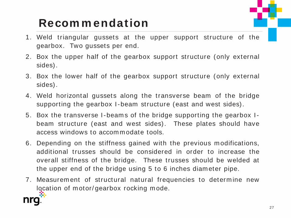
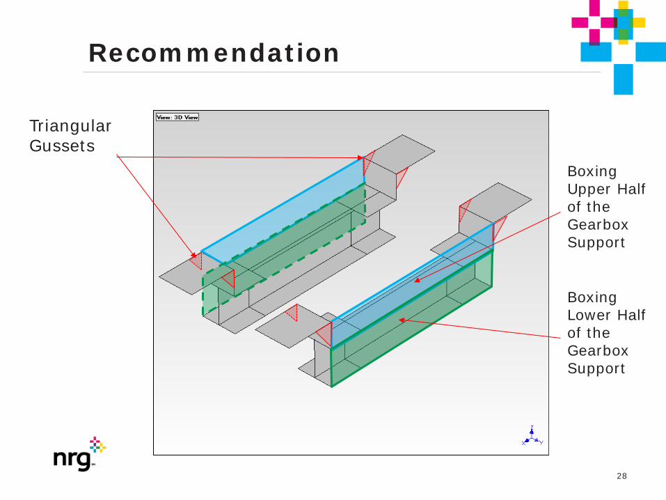
Recommendation 1. Weld triangular gussets at the upper support structure of the
gearbox. Two gussets per end.
2. Box the upper half of the gearbox support structure (only external sides).
3. Box the lower half of the gearbox support structure (only external sides).
4. Weld horizontal gussets along the transverse beam of the bridge supporting the gearbox I-beam structure (east and west sides).
5. Box the transverse I-beams of the bridge supporting the gearbox I-beam structure (east and west sides). These plates should have access windows to accommodate tools.
6. Depending on the stiffness gained with the previous modifications, additional trusses should be considered in order to increase the overall stiffness of the bridge. These trusses should be welded at the upper end of the bridge using 5 to 6 inches diameter pipe.
7. Measurement of structural natural frequencies to determine new location of motor/gearbox rocking mode.
28
Recommendation
Triangular Gussets
Boxing Upper Half of the Gearbox Support
Boxing Lower Half of the Gearbox Support

29
Recommendation
Horizontal web
Boxing I-Beam with Tool Access Windows

30
Recommendation
Trusses welded at the top of the upper flange on both sides of the bridge

31
Cost Effective Fix

32
U3 Fan 304 after fix vibration test Area: Unit #3
Equipment: Acc Fan 304
Recommendation: No Recommendation
Fault: #1: Slight - Structural Vibration Or Resonance
Explanation:
• Vibration levels have reduced to 0.29 ips (7.2 mils). These readings were collected after structural steel modifications were complete. Previous vibration levels were 1.29 ips (32 mils). The modifications have reduced the vibration levels. The resonance continues to be present but the amplification is being controlled.

Thank you!