iwrap 2.2.0 user guide - sparkfun electronics · 15. iwrap configuration examples ... 15.3...
TRANSCRIPT

iWRAP 2.2.0
U s e r G u i d e
V e r s i o n 3 . 3
W e d n e s d a y , S e p t e m b e r 1 2 , 2 0 0 7

2
Copyright © 2000-2007 Bluegiga Technologies
All rights reserved.
Bluegiga Technologies assumes no responsibility for any errors, which may appear in this manual. Furthermore, Bluegiga Technologies reserves the right to alter the hardware, software, and/or specifications detailed herein at any time without notice, and does not make any commitment to update the information contained herein. Bluegiga Technologies’ products are not authorized for use as critical components in life support devices or systems.
The WRAP is a registered trademark of Bluegiga Technologies
The Bluetooth trademark is owned by the Bluetooth SIG Inc., USA, and is licensed to Bluegiga Technologies.
All other trademarks listed herein are owned by their respective owners.

3
Contents:
1. Introduction ...............................................................................................14
2. Getting Started...........................................................................................16
3. iWRAP Modes .............................................................................................17
3.1 Command Mode ........................................................................................18
3.2 Data Mode................................................................................................18
3.3 Multiplexing Mode......................................................................................19
3.4 Audio Mode ..............................................................................................19
4. Technical Details ........................................................................................20
5. Usage .........................................................................................................21
5.1 Typographical Conventions .........................................................................22
5.2 CALL........................................................................................................23
5.2.1 Syntax ...............................................................................................23
5.2.2 Examples............................................................................................24
5.3 CLOSE .....................................................................................................26
5.3.1 Syntax ...............................................................................................26
5.3.2 Examples............................................................................................26
5.4 INQUIRY ..................................................................................................27
5.4.1 Syntax ...............................................................................................27
5.4.2 Examples............................................................................................29
5.5 IC ...........................................................................................................30
5.5.1 Syntax ...............................................................................................30
5.5.2 Examples............................................................................................30
5.6 LIST ........................................................................................................31
5.6.1 Syntax ...............................................................................................31
5.6.2 Examples............................................................................................33
5.7 NAME ......................................................................................................34
5.7.1 Syntax ...............................................................................................34
5.7.2 Examples............................................................................................34
5.8 RESET .....................................................................................................35
5.8.1 Syntax ...............................................................................................35

4
5.9 SELECT ....................................................................................................36
5.9.1 Syntax ...............................................................................................36
5.9.2 Examples............................................................................................36
5.10 INFO ..................................................................................................37
5.10.1 Syntax.............................................................................................37
5.10.2 Examples .........................................................................................37
5.11 AUTH .................................................................................................38
5.11.1 Syntax.............................................................................................38
5.11.2 Examples .........................................................................................38
6. SET.............................................................................................................40
6.1.1 Syntax of SET Commands .....................................................................40
6.1.2 Examples............................................................................................41
6.2 SET PROFILE ............................................................................................42
6.2.1 Syntax ...............................................................................................42
6.2.2 Examples............................................................................................43
6.3 SET BT BDADDR........................................................................................44
6.3.1 Syntax ...............................................................................................44
6.4 SET BT NAME............................................................................................45
6.4.1 Syntax ...............................................................................................45
6.5 SET BT CLASS...........................................................................................46
6.5.1 Syntax ...............................................................................................46
6.6 SET BT LAP...............................................................................................47
6.6.1 Syntax ...............................................................................................47
6.7 SET BT AUTH ............................................................................................49
6.7.1 Syntax ...............................................................................................49
6.8 SET BT PAIR .............................................................................................50
6.8.1 Syntax ...............................................................................................50
6.9 SET BT PAGEMODE ....................................................................................51
6.9.1 Syntax ...............................................................................................51
6.10 SET BT ROLE.......................................................................................53
6.10.1 Syntax.............................................................................................53

5
6.11 SET BT SNIFF ......................................................................................55
6.11.1 Syntax.............................................................................................55
6.12 SET BT POWER ....................................................................................57
6.12.1 Syntax.............................................................................................57
6.12.2 Examples .........................................................................................57
6.13 SET CONTROL AUTOCALL......................................................................59
6.13.1 Syntax.............................................................................................59
6.13.2 Examples .........................................................................................60
6.14 SET CONTROL BAUD.............................................................................62
6.14.1 Syntax.............................................................................................62
6.14.2 Examples .........................................................................................63
6.15 SET CONTROL CD ................................................................................64
6.15.1 Syntax.............................................................................................64
6.16 SET CONTROL CONFIG .........................................................................65
6.16.1 Syntax.............................................................................................65
6.16.2 Examples .........................................................................................66
6.17 SET CONTROL ECHO.............................................................................67
6.17.1 Syntax.............................................................................................67
6.18 SET CONTROL ESCAPE..........................................................................68
6.18.1 Syntax.............................................................................................68
6.18.2 Examples .........................................................................................69
6.19 SET CONTROL INIT ..............................................................................70
6.19.1 Syntax.............................................................................................70
6.19.2 Examples .........................................................................................70
6.20 SET CONTROL MUX ..............................................................................71
6.20.1 Syntax.............................................................................................71
6.20.2 Examples .........................................................................................71
6.20.3 Using Multiplexing Mode.....................................................................72
6.21 SET CONTROL BIND .............................................................................75
6.21.1 Syntax.............................................................................................75
6.21.2 Examples .........................................................................................76
6
6.22 SET CONTROL MSC ..............................................................................77
6.22.1 Syntax.............................................................................................77
6.22.2 Examples .........................................................................................78
7. SET {link_id} .............................................................................................79
7.1 SET {link_id} ACTIVE ................................................................................80
7.1.1 Syntax ...............................................................................................80
7.1.2 Examples............................................................................................80
7.2 SET {link_id} MASTER ...............................................................................81
7.2.1 Syntax ...............................................................................................81
7.2.2 Examples............................................................................................81
7.3 SET {link_id} SLAVE..................................................................................82
7.3.1 Syntax ...............................................................................................82
7.4 SET {link_id} PARK ...................................................................................83
7.4.1 Syntax ...............................................................................................83
7.4.2 Examples............................................................................................83
7.5 SET {link_id} SNIFF ..................................................................................84
7.5.1 Syntax ...............................................................................................84
7.6 SET {link} MSC.........................................................................................85
7.6.1 Syntax ...............................................................................................85
7.6.2 Examples............................................................................................85
7.7 TESTMODE ...............................................................................................86
7.7.1 Syntax ...............................................................................................86
7.8 BER {link_id} ...........................................................................................87
7.8.1 Syntax ...............................................................................................87
7.8.2 Examples............................................................................................87
7.9 RSSI {link_id} ..........................................................................................88
7.9.1 Syntax ...............................................................................................88
7.9.2 Examples............................................................................................88
7.10 TXPOWER ...........................................................................................89
7.10.1 Syntax.............................................................................................89
7.10.2 Examples .........................................................................................89

7
7.11 SDP ...................................................................................................90
7.11.1 Syntax.............................................................................................90
7.11.2 Examples .........................................................................................90
7.12 SDP ADD ............................................................................................92
7.12.1 Syntax.............................................................................................92
7.12.2 Examples .........................................................................................92
7.13 SLEEP ................................................................................................93
7.13.1 Syntax.............................................................................................93
7.14 SCO ENABLE .......................................................................................94
7.14.1 Syntax.............................................................................................94
7.15 SCO OPEN ..........................................................................................95
7.15.1 Syntax.............................................................................................95
7.15.2 Examples .........................................................................................96
7.16 BOOT .................................................................................................97
7.16.1 Syntax.............................................................................................97
7.16.2 Examples .........................................................................................97
7.17 ECHO .................................................................................................98
7.17.1 Syntax.............................................................................................98
7.17.2 Examples .........................................................................................98
7.18 PING {link_id}.....................................................................................99
7.18.1 Syntax.............................................................................................99
7.18.2 Examples .........................................................................................99
7.19 TEST ................................................................................................ 100
7.19.1 Syntax........................................................................................... 100
7.19.2 Examples ....................................................................................... 102
8. iWRAP Events...........................................................................................103
8.1 CONNECT............................................................................................... 104
8.1.1 Syntax ............................................................................................. 104
8.2 INQUIRY_PARTIAL ................................................................................... 105
8.2.1 Syntax ............................................................................................. 105
8.3 NO CARRIER........................................................................................... 106

8
8.3.1 Syntax ............................................................................................. 106
8.4 READY ................................................................................................... 107
8.4.1 Syntax ............................................................................................. 107
8.5 NAME .................................................................................................... 108
8.5.1 Syntax ............................................................................................. 108
8.6 NAME ERROR.......................................................................................... 109
8.6.1 Syntax ............................................................................................. 109
8.7 PAIR...................................................................................................... 110
8.7.1 Syntax ............................................................................................. 110
8.8 RING ..................................................................................................... 111
8.8.1 Syntax ............................................................................................. 111
8.9 SYNTAX ERROR....................................................................................... 112
8.9.1 Syntax ............................................................................................. 112
8.10 AUTH ............................................................................................... 113
8.10.1 Syntax........................................................................................... 113
9. iWRAP Error Messages .............................................................................114
9.1 HCI Errors .............................................................................................. 114
9.2 RFCOMM Errors ....................................................................................... 119
10. Useful Information ...................................................................................121
10.1 Changing Parameters over RS232 with PSTool ....................................... 121
10.2 Using BlueTest over RS232.................................................................. 122
10.3 Switching to HCI Firmware .................................................................. 123
10.4 Firmware Updates over SPI ................................................................. 124
10.5 Firmware Updates over UART............................................................... 124
10.6 Hardware Flow Control........................................................................ 125
10.7 RS232 Connections ............................................................................ 126
10.8 PS Keys Used by iWRAP Firmware ........................................................ 127
10.9 Bluetooth Profiles Overview ................................................................. 128
10.9.1 Generic Access Profile (GAP) ............................................................. 128
10.9.2 RFCOMM ........................................................................................ 128
10.9.3 Service Discovery Protocol (SDP)....................................................... 128

9
10.9.4 Serial Port Profile (SPP).................................................................... 128
10.9.5 Hands-Free Profile (HFP) .................................................................. 128
10.9.6 Dial-up Networking Profile (DUN)....................................................... 129
10.9.7 Object Push Profile (OPP) ................................................................. 129
10.10 Bluetooth Power Saving ...................................................................... 130
10.11 HFP and HFP-AG commands ................................................................ 131
10.12 HFP and HFP-AG messaging................................................................. 132
10.13 Bluetooth profile UUIDs....................................................................... 134
11. Troubleshooting .......................................................................................138
11.1 I get no response from iWRAP? ............................................................ 138
11.2 I changed ‘UART Baud rate’ key, but it didn’t seem to work? .................... 138
11.3 Data coming from the UART is corrupted ............................................... 138
11.4 I’m missing characters when I type ASCII commands.............................. 138
12. Known Issues...........................................................................................139
13. Support ....................................................................................................140
14. Related Documentation ............................................................................141
15. iWRAP Configuration Examples ................................................................142
15.1 Simple SPP Slave ............................................................................... 142
15.2 Simple SPP Master ............................................................................. 144
15.3 Bluetooth Networking with iWRAP and WRAP Access Server ..................... 147
15.4 Dial-up Networking ............................................................................ 149
15.5 OBEX Object Push Profile Server .......................................................... 150
15.6 iWRAP to iWRAP Audio + Data Connection ............................................. 152
15.7 iWRAP to Hands-Free Audio Connection................................................. 153
15.8 iWRAP to Mobile Phone Audio Connection .............................................. 154
15.9 Wireless IO Replacement .................................................................... 155
List of Tables:
Table 1: iWRAP modes and transitions.....................................................................18
Table 2: Technical details ......................................................................................20
Table 3: Power classes as defined in Bluetooth specification .......................................58
Table 4: Multiplexing frame format .........................................................................72
10
Table 5: HCI errors............................................................................................. 116
Table 6: SDP errors ............................................................................................ 118
Table 7: RFCOMM errors...................................................................................... 120
Table 8: HFP supported commands ....................................................................... 131
Table 9: HFP-AG supported commands .................................................................. 131
Table 10: UUIDs and Profiles................................................................................ 137
Table 11: iWRAP known issues ............................................................................. 139
List of Figures:
Figure 1: iWRAP Stack ..........................................................................................14
Figure 2: iWRAP boot prompt .................................................................................16
Figure 3: State Transitions.....................................................................................17
Figure 4: Host-iWRAP-Host communication ..............................................................73
Figure 5: Host-iWRAP-remote device communications................................................73
Figure 6: RS232 connections................................................................................ 126
Figure 7: Slave configuration ............................................................................... 142
Figure 8: Transparent master............................................................................... 144
Figure 9: Configuration for multiple slaves ............................................................. 148
Figure 10: How to open a DUN connection to a mobile phone.................................... 149
Figure 11: Receiving files through OPP .................................................................. 150
Figure 12: Receiving a vCard over OPP .................................................................. 151
Figure 13: ACL data + SCO audio connection setup ................................................. 152
Figure 14: iWRAP to headset audio connection........................................................ 153
Figure 15: HFP connection to a mobile phone ......................................................... 154
Figure 16: Wireless IO replacement connection....................................................... 155

11
VERSION HISTORY
Version: Author: Comments:
1.0 MSa Initial Version, which is beta so information may change
1.1 MSa Feature updates
1.2 MSa Build 18 updates
1.3 MSa Build 19 updates
1.4 MSa Build 20 updates
1.5 MSa Build 21 updates + HS comments
1.6 MSa PAIR event documentation fixed
2.1 MSa iWRAP 2.2.0 updates
2.2 MSa Wireless IO / RS232 connections added
2.3 MSa Spell checked
2.4 MSa HFP commands added, Known issues updated, NO CARRIER event typo fixed
2.5 MSa Minor changes
2.6 MSa Example 15.8 fixed
2.7 MSa SET BT SNIFF descr. improved
2.8 MSa AUTH command / event added. SET CONTROL CONFIG updated.
2.9 MSa HFP command mappings added
3.0 MSa PAGEMODE desc. fixed
Chapter 10.12 added
12
3.1 MSa Error codes updated
3.2 MSa SET BT SNIFF documentation fixed
3.3 MSa Typo in MUX frame format fixed
TERMS & ABBREVIATIONS
Term or Abbreviation: Explanation:
BDR Basic Data Rate
Bluetooth Set of technologies providing audio and data transfer over short-range radio connections
bps Bits per second
CD Carrier Detect
DTR Data Terminal Ready
DUN Dial-Up Networking Profile
EDR Enhanced Data Rate
HCI Host Controller Interface
HFP Hands-Free Profile
HFP-AG Hands-Free audio Gateway
iWRAP Interface for WRAP – a trademark registered by Bluegiga Technologies
L2CAP The Logical Link Control and Adaptation Layer Protocol
OPP Object Push Profile
PARK state Bluetooth low power mode
RFCOMM Serial cable emulation protocol; element of Bluetooth

13
SNIFF mode Bluetooth low power mode
SPP Serial Port Profile
UART Universal Asynchronous Receiver Transmitter
UUID Universally Unique Identifier
VM Virtual Machine
WRAP Wireless Remote Access Platform; Bluegiga Technologies' wireless product family
14
1. INTRODUCTION
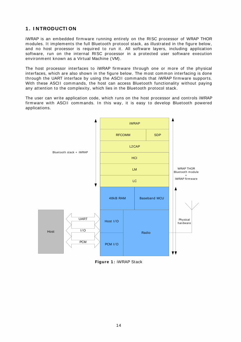
iWRAP is an embedded firmware running entirely on the RISC processor of WRAP THOR modules. It implements the full Bluetooth protocol stack, as illustrated in the figure below, and no host processor is required to run it. All software layers, including application software, run on the internal RISC processor in a protected user software execution environment known as a Virtual Machine (VM).
The host processor interfaces to iWRAP firmware through one or more of the physical interfaces, which are also shown in the figure below. The most common interfacing is done through the UART interface by using the ASCII commands that iWRAP firmware supports. With these ASCII commands, the host can access Bluetooth functionality without paying any attention to the complexity, which lies in the Bluetooth protocol stack.
The user can write application code, which runs on the host processor and controls iWRAP firmware with ASCII commands. In this way, it is easy to develop Bluetooth powered applications.
PCM I/O
Host I/O
Radio
48kB RAM Baseband MCU
LC
LM
HCI
L2CAP
RFCOMM SDP
iWRAP
UART
Host I/O
PCM
Bluetooth stack + iWRAP
Physicalhardware
WRAP THORBluetooth module
+iWRAP firmware
Figure 1: iWRAP Stack

15
In the figure above, a WRAP THOR Bluetooth module equipped with iWRAP firmware is connected to a host system by using the UART interface.
1. If the host system has a processor, software can be used to control iWRAP by using ASCII based commands.
2. If there is no need to control iWRAP, or the host system does not have a processor, iWRAP can be configured to be totally transparent, in which case it only accepts connections or automatically opens them. Not all the functionality will be available with this solution.
3. GPIO lines that WRAP THOR modules offer can also be used together with iWRAP to achieve additional functionality, such as DTR signaling or Carrier Detect signals.
4. PCM interface can be used to transmit audio data over a Bluetooth link.
16
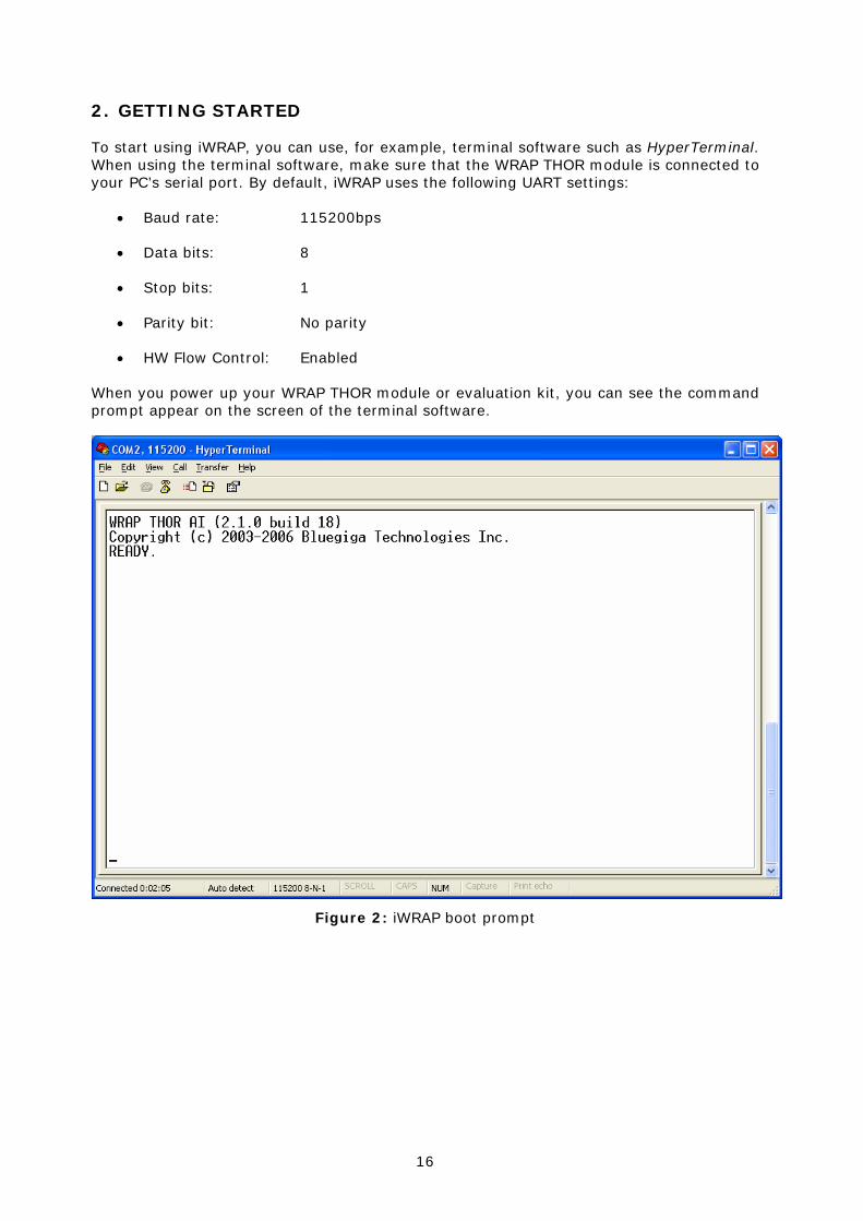
2. GETTING STARTED
To start using iWRAP, you can use, for example, terminal software such as HyperTerminal. When using the terminal software, make sure that the WRAP THOR module is connected to your PC’s serial port. By default, iWRAP uses the following UART settings:
• Baud rate: 115200bps
• Data bits: 8
• Stop bits: 1
• Parity bit: No parity
• HW Flow Control: Enabled
When you power up your WRAP THOR module or evaluation kit, you can see the command prompt appear on the screen of the terminal software.
Figure 2: iWRAP boot prompt

17
3. IWRAP MODES
iWRAP has two operational modes, command mode and data mode. Command mode is the default mode when there are no connections. It is possible to switch between modes at any time when there are one or more active connections. Data mode is not available if there are no active connections, because obviously there is no data available, nor can it be sent anywhere.
- CONNECT- RING- Escape sequence- SELECT cmd.
CommandMode
Data Mode
- NO CARRIER- Escape sequence- DTR switch
Figure 3: State Transitions
Switching from data mode to command mode is issued by using the following escape sequence:
<At least 1 second sleep> esc esc esc <at least 1 second sleep>
esc = escape character
or it can also be done by using DTR signals.
The same sequence or the SELECT command can be used to return to data mode.
Note:
• When iWRAP enters command mode, a READY event occurs
(Unless it is masked away by using the “SET CONTROL ECHO” command.)
• The escape character can be changed by using the “SET CONTROL ESCAPE”–command.
• DTR mode can be enabled by using the “SET CONTROL ESCAPE” command.

18
3.1 Command Mode
Command mode is the default mode when iWRAP is powered up. In command mode, ASCII commands can be entered to iWRAP to perform various functions.
Note:
• Incoming data from remote devices is buffered when iWRAP is in command mode.
• Because of the embedded nature of iWRAP, buffering capabilities are low and only small amounts of data can be received to buffers. The amount of data which can be buffered depends on the firmware version and the state of iWRAP. Usually, it is approximately 2 Kbytes, but may vary radically.
3.2 Data Mode
Data mode is the default mode when there are one or more connections. In data mode, all data is sent transparently from UART over the Bluetooth RFCOMM link to the other device and vice versa.
Initial mode Target mode Requirements for transition from initial mode to target mode
Command Mode (no active connection)
In this mode, ASCII commands can be given to iWRAP.
Data Mode A connection is successfully created by using the CALL command. (The CONNECT event is used to indicate a successful link creation.)
A remote device has connected us. (The RING event is used to indicate incoming connections.)
Data Mode
In this mode, all data can be sent transparently from RS-232 over the Bluetooth RFCOMM link to the other device.
Command Mode The user switches mode by using escape sequence <1s>esc esc esc<1s> or by setting the DTR low.
A link is terminated (closed by the remote device or by link loss). (The NO CARRIER event is used to indicate link termination.)
Command Mode (active connection)
In this mode, ASCII commands can be given to iWRAP.
Data Mode User switches mode either by using escape sequence <1s>esc esc esc<1s>, or by using command SELECT.
Table 1: iWRAP modes and transitions

19
3.3 Multiplexing Mode
In iWRAP 2.1.0 and newer, there is a special mode called “multiplexing mode”. In this mode, iWRAP does not have separate commands or data modes, but data, commands and events are all handled in one single mode. There is, however, a special protocol to separate commands and events from the actual data. This protocol must be used between the host system and iWRAP firmware.
The advantage of this multiplexing mode is that several Bluetooth connections can be handled simultaneously and there is no need to do time consuming data-command-data mode switching.
To learn more about multiplexing mode, please see the description of “SET CONTROL MUX”.
3.4 Audio Mode
IWRAP 2.2.0 and newer support several Bluetooth audio profiles, such as Hands-Free and Hands-Free Audio Gateway.
Audio mode is similar to multiplexing mode, that is, data can be transferred and iWRAP commands can be given in the same mode. However, the difference to multiplexing mode is that no special packet mode needs to be used.

20
4. TECHNICAL DETAILS
Feature: Value:
MAX simultaneous ACL connections 4
MAX simultaneous SCO connections 1
MAX data rate
600Kbps (WT12/WT11 to BT2.0 USB dongle)
550Kbps (WT12/WT11 to WT12/WT11)
450Kbps (WT12/WT11 to BT1.1-BT1.2 device)
MAX UART baud rate 921600 bps
MIN transmission delay 8-15ms
PIN code length Configurable from 0 to 16 characters
Encryption length Configurable from 0 to 128 bits
MAX simultaneous pairings 16
MAX Friendly name length Configurable up to 248 characters
RFCOMM Packet size Configurable from 21 to 1008
Supported Bluetooth profiles GAP, SPP, Hands-Free, Hands-Free Audio-Gateway, OPP*, DUN*
Supported power saving modes Sniff, Park and deep sleep
Table 2: Technical details
*) Limited support

21
5. USAGE
iWRAP can be used and controlled from the host system by sending ASCII commands through the UART interface to iWRAP.
When installed and configured, the module can be commanded from the host with the following ASCII commands:
• BER
• CALL
• CLOSE
• HELP
• INFO
• INQUIRY
• IC
• LIST
• NAME
• RSSI
• RESET
• SCO
• SDP
• SELECT
• SET
• SLEEP
• TESTMODE
• TXPOWER
• BCSP_ENABLE
• BOOT
• TEST
• PING
• ECHO
Note:
These commands must end with a line feed “\n” character.
22
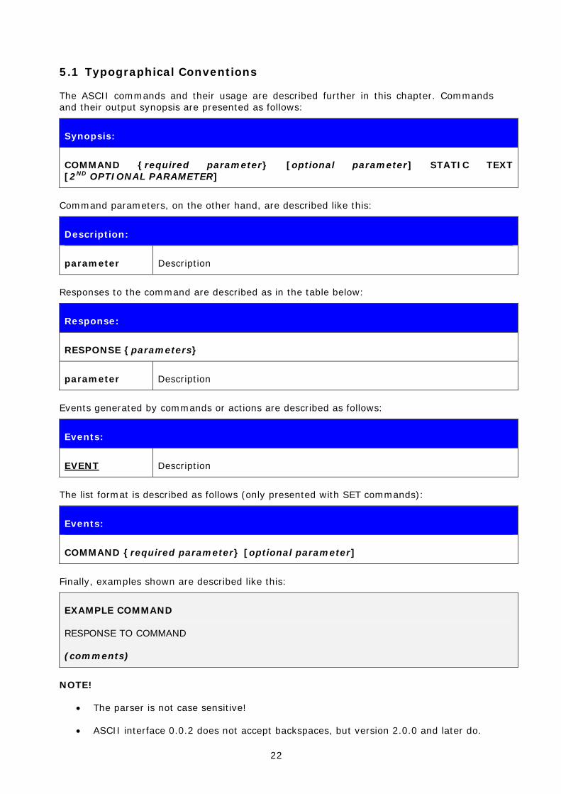
5.1 Typographical Conventions
The ASCII commands and their usage are described further in this chapter. Commands and their output synopsis are presented as follows:
Synopsis:
COMMAND {required parameter} [optional parameter] STATIC TEXT [2ND OPTIONAL PARAMETER]
Command parameters, on the other hand, are described like this:
Description:
parameter Description
Responses to the command are described as in the table below:
Response:
RESPONSE {parameters}
parameter Description
Events generated by commands or actions are described as follows:
Events:
EVENT Description
The list format is described as follows (only presented with SET commands):
Events:
COMMAND {required parameter} [optional parameter]
Finally, examples shown are described like this:
EXAMPLE COMMAND
RESPONSE TO COMMAND
(comments)
NOTE!
• The parser is not case sensitive!
• ASCII interface 0.0.2 does not accept backspaces, but version 2.0.0 and later do.

23
5.2 CALL
The CALL command is used to initiate connections to the remote device. Connections are closed by using command CLOSE. Currently open connections can be viewed by using command LIST.
5.2.1 Syntax
Synopsis:
CALL {address} {target} {connect_mode} [MTU {packet size}]
Description:
address Bluetooth address of the remote device
target RFCOMM, HFP or HFP-AG target for the connection. The target can be one of the following:
channel
RFCOMM channel number
HFP channel number
HFP-AG channel number
Format: xx (hex)
uuid16
16-bit UUID for searching channel
Format: xxxx (hex)
uuid32
32-bit UUID for searching channel
Format: xxxxxxxx (hex)
uuid128
128-bit UUID for searching channel
Format: xxxxxxxx-xxxx-xxxx-xxxx-xxxxxxxxxxxx (hex)
connect_mode Defines the connection mode to be established.
Possible modes are:
24
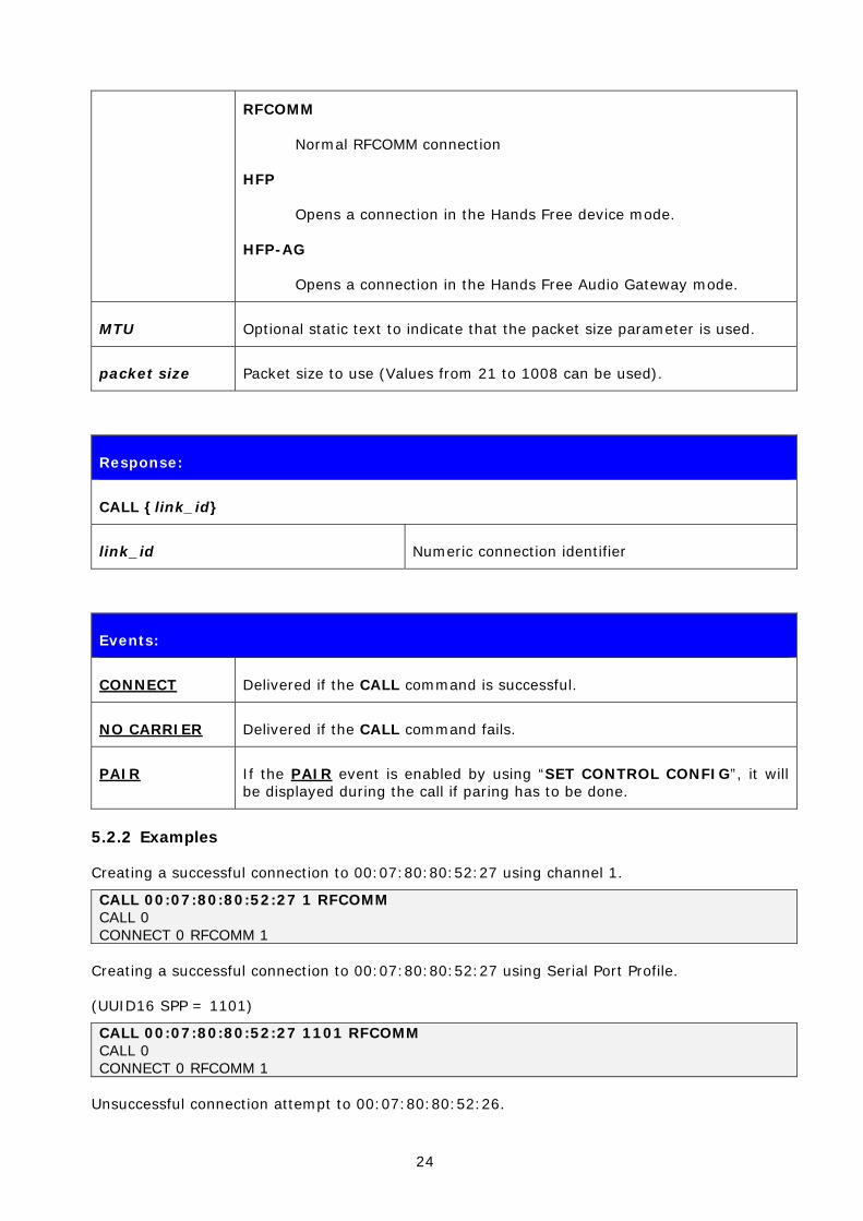
RFCOMM
Normal RFCOMM connection
HFP
Opens a connection in the Hands Free device mode.
HFP-AG
Opens a connection in the Hands Free Audio Gateway mode.
MTU Optional static text to indicate that the packet size parameter is used.
packet size Packet size to use (Values from 21 to 1008 can be used).
Response:
CALL {link_id}
link_id Numeric connection identifier
Events:
CONNECT Delivered if the CALL command is successful.
NO CARRIER Delivered if the CALL command fails.
PAIR If the PAIR event is enabled by using “SET CONTROL CONFIG”, it will be displayed during the call if paring has to be done.
5.2.2 Examples
Creating a successful connection to 00:07:80:80:52:27 using channel 1.
CALL 00:07:80:80:52:27 1 RFCOMM CALL 0 CONNECT 0 RFCOMM 1
Creating a successful connection to 00:07:80:80:52:27 using Serial Port Profile.
(UUID16 SPP = 1101)
CALL 00:07:80:80:52:27 1101 RFCOMM CALL 0 CONNECT 0 RFCOMM 1
Unsuccessful connection attempt to 00:07:80:80:52:26.

25
CALL 00:07:80:80:52:26 1 RFCOMM CALL 0 NO CARRIER 0 ERROR 406 RFC_CONNECTION_FAILED
Creating a successful connection to 00:07:80:80:52:27 with MTU 600.
CALL 00:07:80:80:52:27 1101 RFCOMM MTU 600 CALL 0 CONNECT 0 RFCOMM 1
NOTE!
If CALL is used with CHANNEL instead of UUID, it will be on average around 300ms faster, since there is no need to do service discovery. However, the serial port profile (SPP) channel must be known. Notice that the channel for a specific service may vary between different Bluetooth devices.
In iWRAP, the channel for SPP is always 1.

26
5.3 CLOSE
Command CLOSE is used to terminate a previously opened connection.
5.3.1 Syntax
Synopsis:
CLOSE {link_id}
Description:
link_id Numeric connection identifier from a previously used command CALL or from event RING.
Response:
No response
Events:
NO CARRIER This event is delivered after the link is closed.
5.3.2 Examples
Closing an active connection:
CALL 00:60:57:a6:56:49 1103 RFC CALL 0 CONNECT 0 RFCOMM 1 [+++] (mode switch) READY. CLOSE 0 NO CARRIER 0 ERROR 0
27
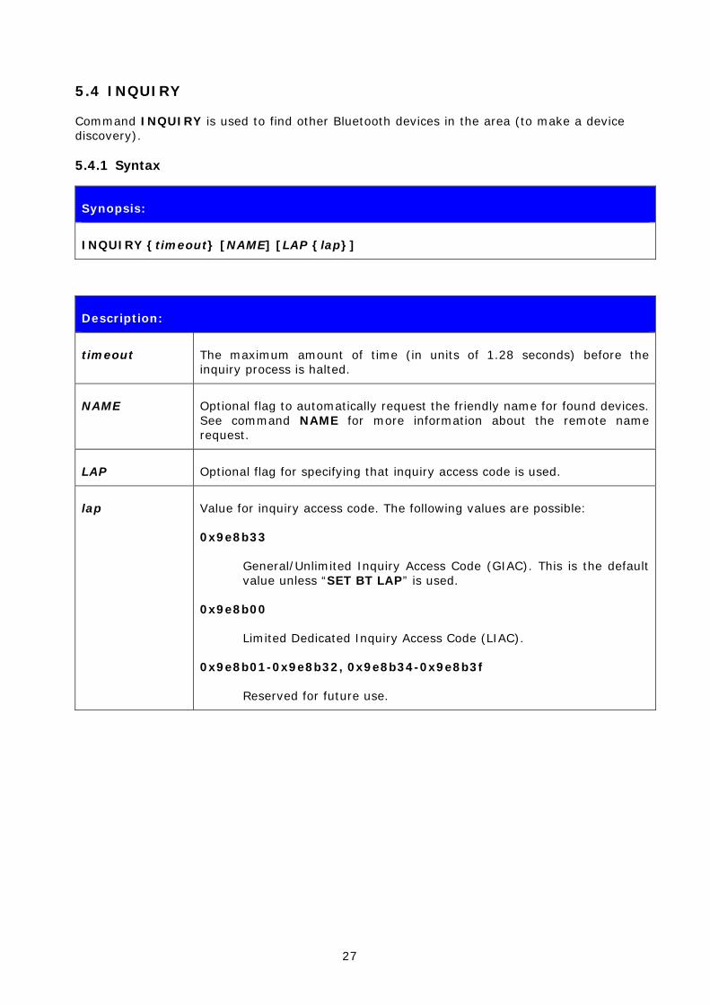
5.4 INQUIRY
Command INQUIRY is used to find other Bluetooth devices in the area (to make a device discovery).
5.4.1 Syntax
Synopsis:
INQUIRY {timeout} [NAME] [LAP {lap}]
Description:
timeout The maximum amount of time (in units of 1.28 seconds) before the inquiry process is halted.
NAME Optional flag to automatically request the friendly name for found devices. See command NAME for more information about the remote name request.
LAP Optional flag for specifying that inquiry access code is used.
lap Value for inquiry access code. The following values are possible:
0x9e8b33
General/Unlimited Inquiry Access Code (GIAC). This is the default value unless “SET BT LAP” is used.
0x9e8b00
Limited Dedicated Inquiry Access Code (LIAC).
0x9e8b01-0x9e8b32, 0x9e8b34-0x9e8b3f
Reserved for future use.
28
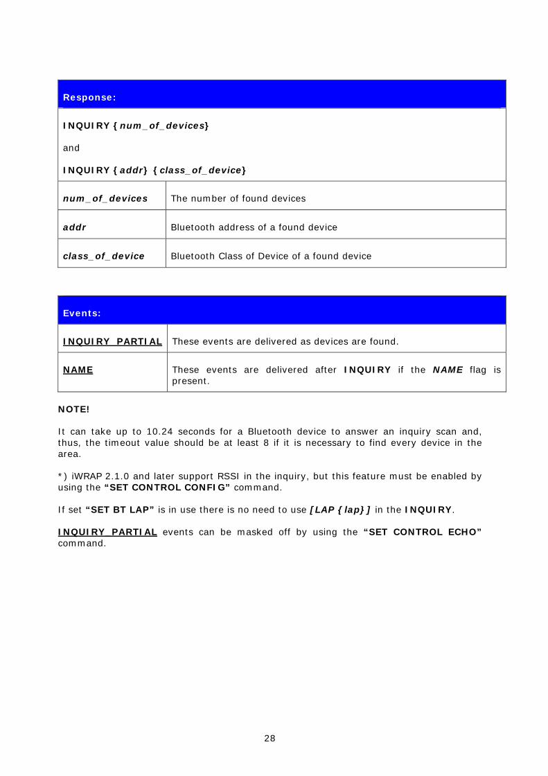
Response:
INQUIRY {num_of_devices}
and
INQUIRY {addr} {class_of_device}
num_of_devices The number of found devices
addr Bluetooth address of a found device
class_of_device Bluetooth Class of Device of a found device
Events:
INQUIRY_PARTIAL These events are delivered as devices are found.
NAME These events are delivered after INQUIRY if the NAME flag is present.
NOTE!
It can take up to 10.24 seconds for a Bluetooth device to answer an inquiry scan and, thus, the timeout value should be at least 8 if it is necessary to find every device in the area.
*) iWRAP 2.1.0 and later support RSSI in the inquiry, but this feature must be enabled by using the “SET CONTROL CONFIG” command.
If set “SET BT LAP” is in use there is no need to use [LAP {lap}] in the INQUIRY.
INQUIRY_PARTIAL events can be masked off by using the “SET CONTROL ECHO” command.

29
5.4.2 Examples
Basic INQUIRY command:
INQUIRY 1 INQUIRY_PARTIAL 00:14:a4:8b:76:9e 72010c INQUIRY_PARTIAL 00:10:c6:62:bb:9b 1e010c INQUIRY_PARTIAL 00:10:c6:4d:62:5c 72010c INQUIRY_PARTIAL 00:10:c6:3a:d8:b7 72010c INQUIRY_PARTIAL 00:02:ee:d1:80:6d 520204 INQUIRY_PARTIAL 00:10:c6:62:bb:fa 1c010c INQUIRY 6 INQUIRY 00:14:a4:8b:76:9e 72010c INQUIRY 00:10:c6:62:bb:9b 1e010c INQUIRY 00:10:c6:4d:62:5c 72010c INQUIRY 00:10:c6:3a:d8:b7 72010c INQUIRY 00:02:ee:d1:80:6d 520204 INQUIRY 00:10:c6:62:bb:fa 1c010c
An INQUIRY command with NAME resolution:
INQUIRY 1 NAME INQUIRY_PARTIAL 00:10:c6:3a:d8:b7 72010c INQUIRY_PARTIAL 00:10:c6:62:bb:9b 1e010c INQUIRY_PARTIAL 00:14:a4:8b:76:9e 72010c INQUIRY 3 INQUIRY 00:10:c6:3a:d8:b7 72010c INQUIRY 00:10:c6:62:bb:9b 1e010c INQUIRY 00:14:a4:8b:76:9e 72010c NAME 00:10:c6:3a:d8:b7 "TOM" NAME 00:10:c6:62:bb:9b "CSLTJANI" NAME 00:14:a4:8b:76:9e "SWLTMIKKO_3"
An INQUIRY command with LAP in use:
INQUIRY 3 LAP 9e8b11 INQUIRY_PARTIAL 00:07:80:80:52:15 111111 INQUIRY_PARTIAL 00:07:80:80:52:27 111111 INQUIRY 2 INQUIRY 00:07:80:80:52:15 111111 INQUIRY 00:07:80:80:52:27 111111
An INQUIRY command with RSSI enabled:
INQUIRY 1 INQUIRY_PARTIAL 00:10:c6:62:bb:9b 1e010c "" -71 INQUIRY_PARTIAL 00:10:c6:4d:62:5c 72010c "" -73 INQUIRY_PARTIAL 00:10:c6:3a:d8:b7 72010c "" -73 INQUIRY 5 INQUIRY 00:10:c6:62:bb:9b 1e010c INQUIRY 00:10:c6:4d:62:5c 72010c INQUIRY 00:10:c6:3a:d8:b7 72010c
30
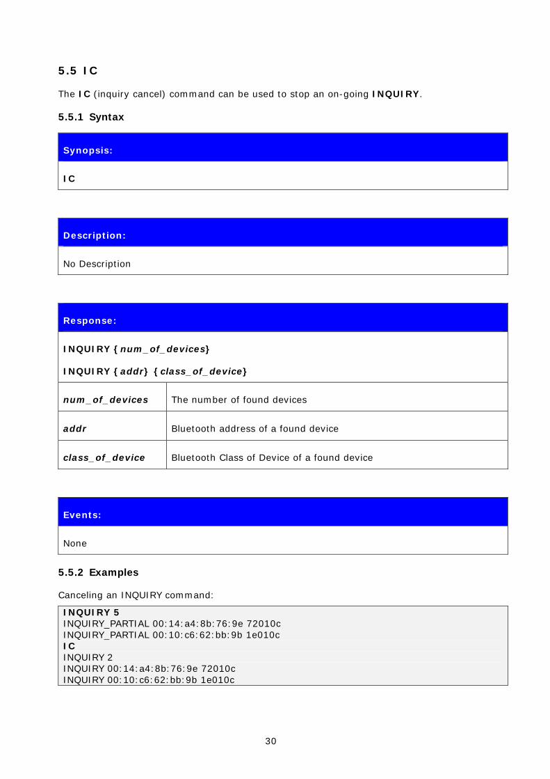
5.5 IC
The IC (inquiry cancel) command can be used to stop an on-going INQUIRY.
5.5.1 Syntax
Synopsis:
IC
Description:
No Description
Response:
INQUIRY {num_of_devices}
INQUIRY {addr} {class_of_device}
num_of_devices The number of found devices
addr Bluetooth address of a found device
class_of_device Bluetooth Class of Device of a found device
Events:
None
5.5.2 Examples
Canceling an INQUIRY command:
INQUIRY 5 INQUIRY_PARTIAL 00:14:a4:8b:76:9e 72010c INQUIRY_PARTIAL 00:10:c6:62:bb:9b 1e010c IC INQUIRY 2 INQUIRY 00:14:a4:8b:76:9e 72010c INQUIRY 00:10:c6:62:bb:9b 1e010c

31
5.6 LIST
Command LIST shows information about active connections.
5.6.1 Syntax
Synopsis:
LIST
Description:
No Description
Response:
LIST {num_of_connections}
LIST {link_id} CONNECTED RFCOMM {blocksize} 0 0 {elapsed_time} {local_msc} {remote_msc} {addr} {channel} {direction} {powermode} {role} {crypt}*
link_id Numeric connection identifier
Blocksize RFCOMM data packet size, that is, how many bytes of data can be sent in one packet
elapse_time Link life time in seconds
local_msc Local serial port status bits, "8d" is a normal value
remote_msc Remote serial port status bits, "8d" is a normal value
Addr Bluetooth device address of the remote device
channel RFCOMM channel number at remote device
direction Direction of the link. The possible values are:
OUTGOING
The link is initiated by a local device (by using command CALL)
INCOMING
32
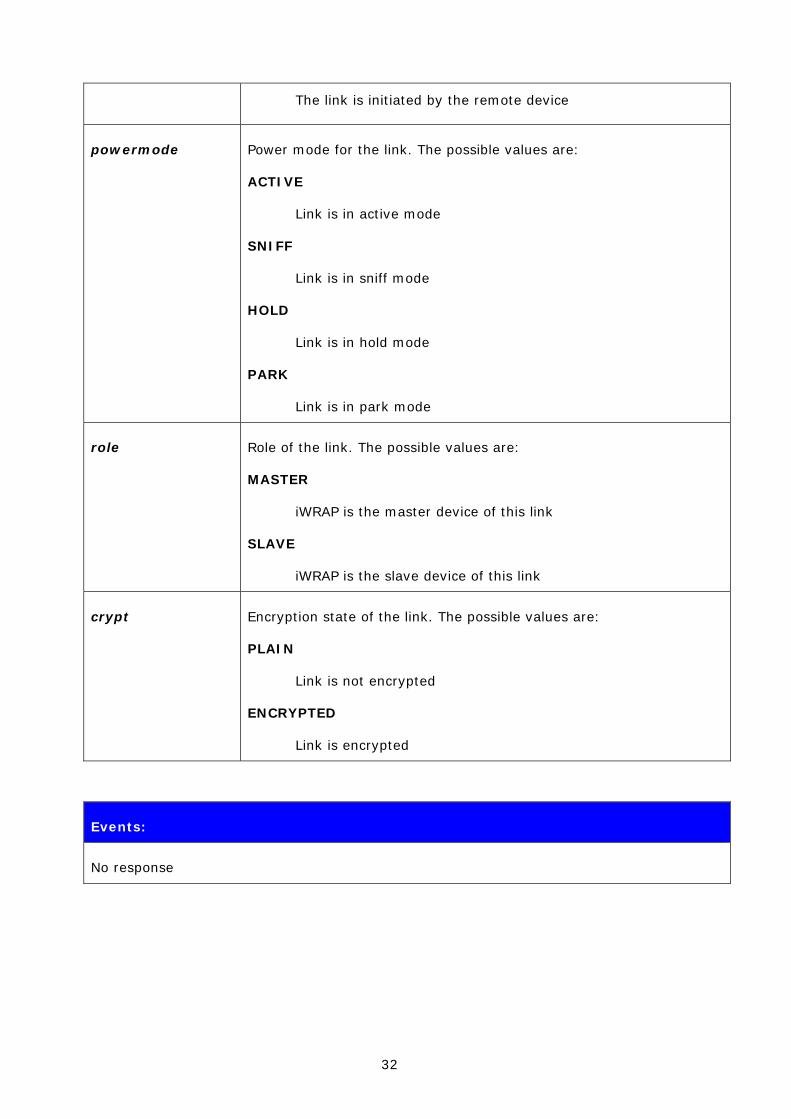
The link is initiated by the remote device
powermode Power mode for the link. The possible values are:
ACTIVE
Link is in active mode
SNIFF
Link is in sniff mode
HOLD
Link is in hold mode
PARK
Link is in park mode
role Role of the link. The possible values are:
MASTER
iWRAP is the master device of this link
SLAVE
iWRAP is the slave device of this link
crypt Encryption state of the link. The possible values are:
PLAIN
Link is not encrypted
ENCRYPTED
Link is encrypted
Events:
No response

33
5.6.2 Examples
Listing active connections
LIST LIST 1 LIST 0 CONNECTED RFCOMM 320 0 0 3 8d 8d 00:60:57:a6:56:49 1 OUTGOING ACTIVE MASTER PLAIN

34
5.7 NAME
Command NAME is used to retrieve the friendly name of the device.
5.7.1 Syntax
Synopsis:
NAME {address}
Description:
address Address of the Bluetooth device
Response:
No response
Events:
NAME These events are delivered after INQUIRY if the NAME flag is present.
NAME_ERROR These events are delivered if name resolution fails.
5.7.2 Examples
Successful name resolution
NAME 00:07:80:bf:bf:01 NAME 00:07:80:bf:bf:01 “iWRAP_2.1.0”
Unsuccessful name resolution
NAME 00:07:80:bf:bf:01 NAME ERROR 0x104 00:07:80:bf:bf:01 HCI_ERROR_PAGE_TIMEOUT

35
5.8 RESET
Command RESET is used to reset iWRAP.
5.8.1 Syntax
Synopsis:
RESET
Description:
No description
Response:
No response

36
5.9 SELECT
Command SELECT is used to switch to data mode.
5.9.1 Syntax
Synopsis:
SELECT {link_id}
Description:
link_id Numeric connection identifier
Response:
No response if a valid link is selected. iWRAP goes to data mode of the link link_id.
Events:
SYNTAX ERROR This event occurs if an invalid link_id is given
5.9.2 Examples
Changing between links
LIST LIST 2 LIST 0 CONNECTED RFCOMM 668 0 0 243 8d 8d 00:07:80:80:38:77 1 OUTGOING ACTIVE MASTER ENCRYPTED LIST 1 CONNECTED RFCOMM 668 0 0 419 8d 8d 00:07:80:80:36:85 1 OUTGOING ACTIVE MASTER ENCRYPTED SELECT 1 (iWRAP goes to DATA mode – Device: 00:07:80:80:36:85)
37
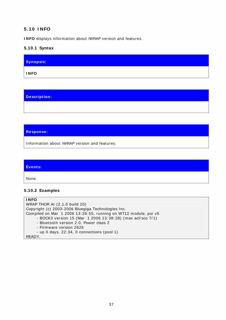
5.10 INFO
INFO displays information about iWRAP version and features.
5.10.1 Syntax
Synopsis:
INFO
Description:
Response:
Information about iWRAP version and features.
Events:
None.
5.10.2 Examples
INFO WRAP THOR AI (2.1.0 build 20) Copyright (c) 2003-2006 Bluegiga Technologies Inc. Compiled on Mar 1 2006 13:39:55, running on WT12 module, psr v5 - BOCK3 version 15 (Mar 1 2006 13:38:28) (max acl/sco 7/1) - Bluetooth version 2.0, Power class 2 - Firmware version 2626 - up 0 days, 22:34, 0 connections (pool 1) READY.
38
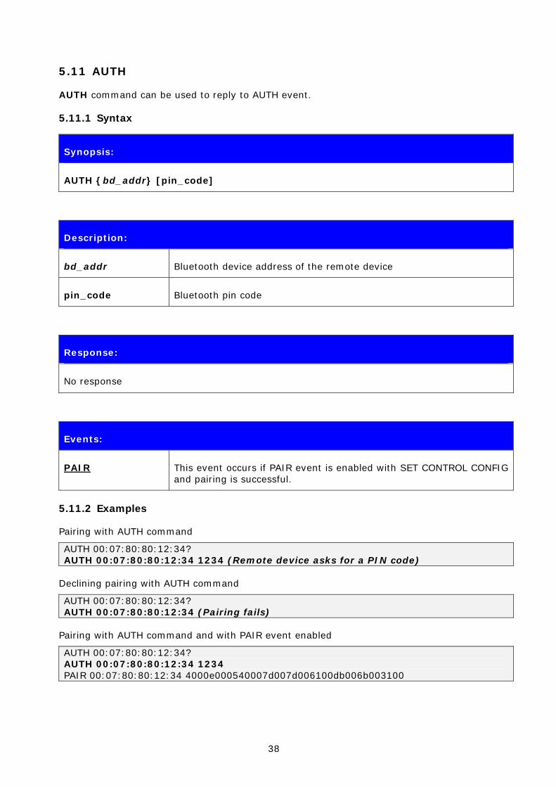
5.11 AUTH
AUTH command can be used to reply to AUTH event.
5.11.1 Syntax
Synopsis:
AUTH {bd_addr} [pin_code]
Description:
bd_addr Bluetooth device address of the remote device
pin_code Bluetooth pin code
Response:
No response
Events:
PAIR This event occurs if PAIR event is enabled with SET CONTROL CONFIG and pairing is successful.
5.11.2 Examples
Pairing with AUTH command
AUTH 00:07:80:80:12:34? AUTH 00:07:80:80:12:34 1234 (Remote device asks for a PIN code)
Declining pairing with AUTH command
AUTH 00:07:80:80:12:34? AUTH 00:07:80:80:12:34 (Pairing fails)
Pairing with AUTH command and with PAIR event enabled
AUTH 00:07:80:80:12:34? AUTH 00:07:80:80:12:34 1234 PAIR 00:07:80:80:12:34 4000e000540007d007d006100db006b003100

39
NOTE:
If pin code is set with “SET BT AUTH” iWRAP can choose the pin code after AUTH event and it does not need to be same as defined with SET BT AUTH. However if no pin code is set in iWRAP the remote end can choose the pin code and “AUTH {bd_addr} [pin_code]” command must use the same.

40
6. SET
With the SET command, you can display or configure different iWRAP configuration values.
6.1.1 Syntax of SET Commands
Synopsis:
SET [{category} {option} {value}]
Description:
Without any parameters, SET displays the current configuration.
category Category of setting
PROFILE
Enables or disables the Bluetooth profiles iWRAP can support.
BT
Changes different Bluetooth related settings. See SET BT for more information about options.
CONTROL
Changes different iWRAP settings. See SET CONTROL for more information about options.
link_id
This command is used to control the various settings related to Bluetooth links in iWRAP. These are, for example, master, slave and power save modes (SNIFF, PARK, and ACTIVE).
option Option name, which depends on the category. See the following sections for more information.
value Value for the option. See the following sections for more information.
41
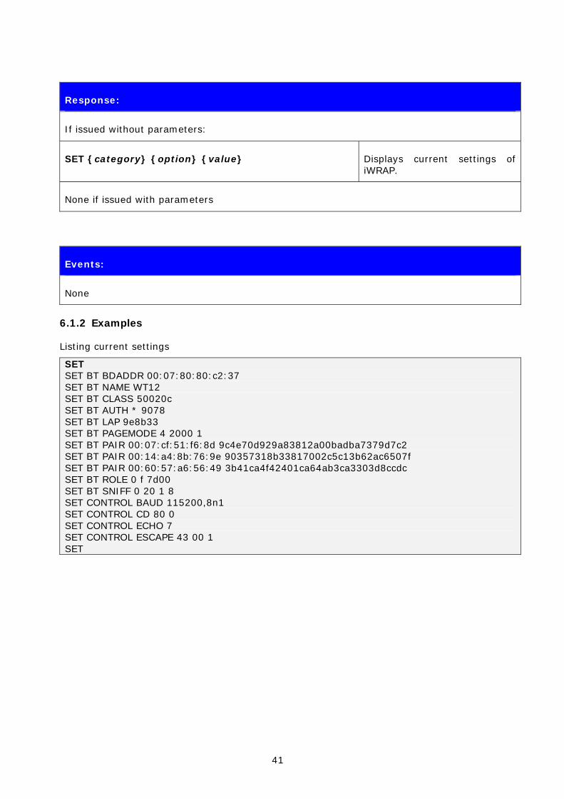
Response:
If issued without parameters:
SET {category} {option} {value} Displays current settings of iWRAP.
None if issued with parameters
Events:
None
6.1.2 Examples
Listing current settings
SET SET BT BDADDR 00:07:80:80:c2:37 SET BT NAME WT12 SET BT CLASS 50020c SET BT AUTH * 9078 SET BT LAP 9e8b33 SET BT PAGEMODE 4 2000 1 SET BT PAIR 00:07:cf:51:f6:8d 9c4e70d929a83812a00badba7379d7c2 SET BT PAIR 00:14:a4:8b:76:9e 90357318b33817002c5c13b62ac6507f SET BT PAIR 00:60:57:a6:56:49 3b41ca4f42401ca64ab3ca3303d8ccdc SET BT ROLE 0 f 7d00 SET BT SNIFF 0 20 1 8 SET CONTROL BAUD 115200,8n1 SET CONTROL CD 80 0 SET CONTROL ECHO 7 SET CONTROL ESCAPE 43 00 1 SET
42
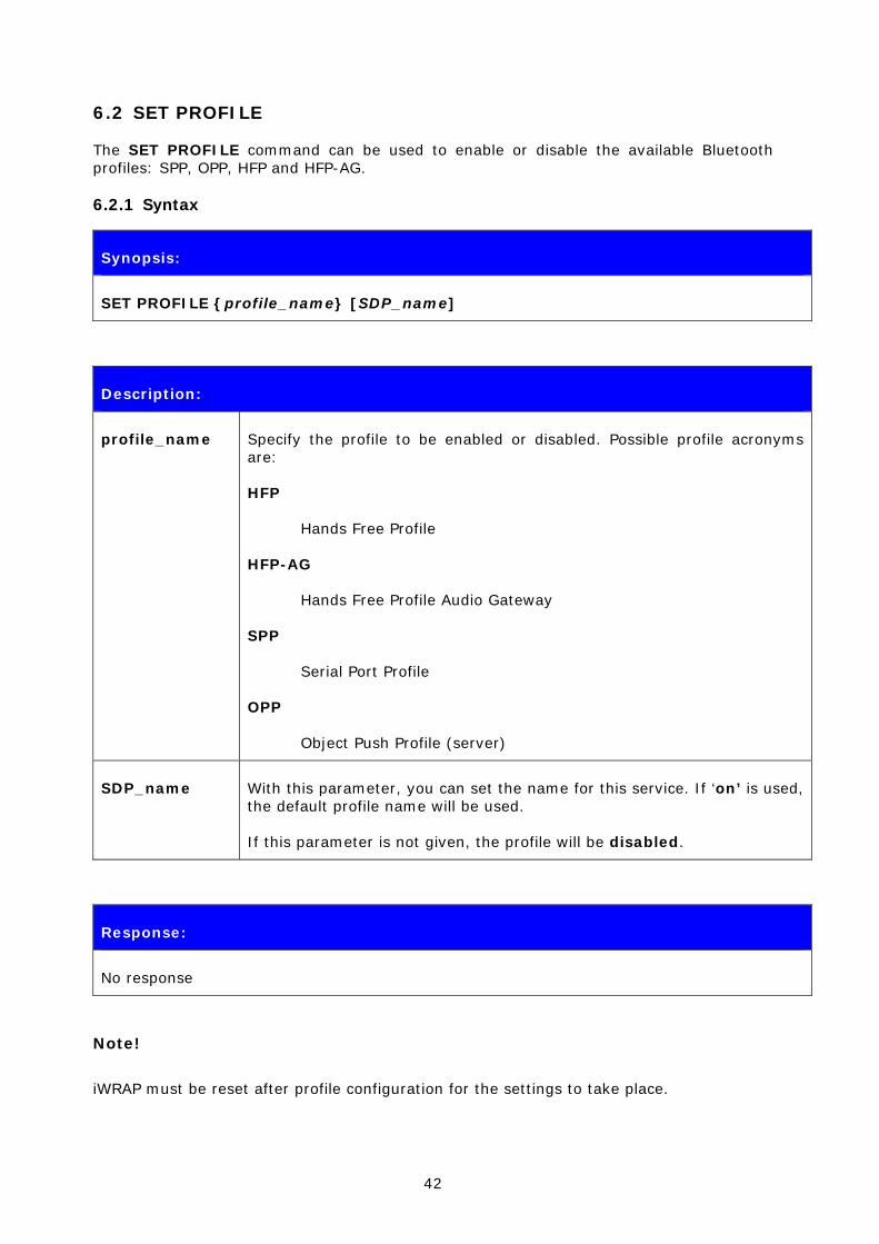
6.2 SET PROFILE
The SET PROFILE command can be used to enable or disable the available Bluetooth profiles: SPP, OPP, HFP and HFP-AG.
6.2.1 Syntax
Synopsis:
SET PROFILE {profile_name} [SDP_name]
Description:
profile_name Specify the profile to be enabled or disabled. Possible profile acronyms are:
HFP
Hands Free Profile
HFP-AG
Hands Free Profile Audio Gateway
SPP
Serial Port Profile
OPP
Object Push Profile (server)
SDP_name With this parameter, you can set the name for this service. If ‘on’ is used, the default profile name will be used.
If this parameter is not given, the profile will be disabled.
Response:
No response
Note!
iWRAP must be reset after profile configuration for the settings to take place.
43
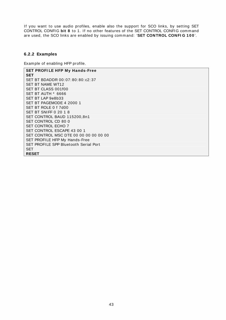
If you want to use audio profiles, enable also the support for SCO links, by setting SET CONTROL CONFIG bit 8 to 1. If no other features of the SET CONTROL CONFIG command are used, the SCO links are enabled by issuing command: ‘SET CONTROL CONFIG 100’.
6.2.2 Examples
Example of enabling HFP profile.
SET PROFILE HFP My Hands-Free SET SET BT BDADDR 00:07:80:80:c2:37 SET BT NAME WT12 SET BT CLASS 001f00 SET BT AUTH * 6666 SET BT LAP 9e8b33 SET BT PAGEMODE 4 2000 1 SET BT ROLE 0 f 7d00 SET BT SNIFF 0 20 1 8 SET CONTROL BAUD 115200,8n1 SET CONTROL CD 80 0 SET CONTROL ECHO 7 SET CONTROL ESCAPE 43 00 1 SET CONTROL MSC DTE 00 00 00 00 00 00 SET PROFILE HFP My Hands-Free SET PROFILE SPP Bluetooth Serial Port SET RESET
44
6.3 SET BT BDADDR
SET BT BDADDR shows the local device’s Bluetooth address.
6.3.1 Syntax
Synopsis:
No description, since the value is read only.
Description:
No description
Response:
None
Events:
None
List format:
SET BT BDADDR {bd_addr}
bd_addr Bluetooth device address of the local device
Note:
This value is read-only!
45
6.4 SET BT NAME
SET BT NAME shows or sets the local device’s friendly name.
6.4.1 Syntax
Synopsis:
SET BT NAME {friendly_name}
Description:
friendly_name Friendly name of the local device
Response:
None
Events:
SYNTAX ERROR This event occurs if incorrect parameters are given
List format:
SET BT NAME {friendly_name}
Note:
The maximum length of a friendly name is 16 characters in iWRAP 2.0.2 and older. In iWRAP 2.1.0 and newer versions, the maximum length is 256 characters.
If friendly_name is left empty, some devices (like PCs or PDAs) may have problems showing the device in the inquiry.
46
6.5 SET BT CLASS
SET BT CLASS shows or sets the local device’s Class-of-Device (CoD).
Class of device is a parameter, which is received during the device discovery procedure, indicating the type of device and which services are supported.
6.5.1 Syntax
Synopsis:
SET BT CLASS {class_of_device}
Description:
class_of_device CoD of the local device
Response:
None
Events:
SYNTAX ERROR This event occurs if incorrect parameters are given
List format:
SET BT CLASS {class_of_device}
47
6.6 SET BT LAP
This command configures the Inquiry Access code (IAC) that iWRAP uses. IAC is used in inquiries and inquiry responses.
6.6.1 Syntax
Synopsis:
SET BT LAP {iac}
Description:
iac Value for the inquiry access code. The following values are possible:
0x9e8b33
General/Unlimited Inquiry Access Code (GIAC). This is the default value.
0x9e8b00
Limited Dedicated Inquiry Access Code (LIAC).
0x9e8b01 - 0x9e8b32 and 0x9e8b34-0x9e8b3f
Reserved for future use.
Response:
None
Events:
SYNTAX ERROR This event occurs if incorrect parameters are given
List format:
SET BT LAP {iac}

48
Note:
IAC is very useful in cases where the module needs to be visible in the inquiry but only for dedicated devices, such as other iWRAP modules, but not for standard devices like PCs or mobile phones. When the value of IAC is the default one (0x9e8b33) it is visible for all devices capable of making an inquiry. On the other hand, when one of the following values 0x9e8b01-0x9e8b32 and 0x9e8b34-0x9e8b3f is used, only devices sharing the same code will see each other in the inquiry. This will also speed up the inquiry process since only the devices we want to see will respond, and not other random Bluetooth devices.
See also: INQUIRY

49
6.7 SET BT AUTH
SET BT AUTH shows or sets the local device’s PIN code.
6.7.1 Syntax
Synopsis:
SET BT AUTH * {pin_code}
Description:
pin_code PIN code for authorized connections. Authorization is required if this option is present. The PIN code can be from 0 to 16 digits.
Response:
None
Events:
SYNTAX ERROR This event occurs if incorrect parameters are given
List format:
If PIN code is not in use, SET BT AUTH * is not displayed
SET BT AUTH * {pin_code} If PIN code is set
Note:
If command “SET BT AUTH *” is given, PIN code will be disabled and no encryption can be used.

50
6.8 SET BT PAIR
SET BT PAIR displays or configures the local device’s pairing information.
6.8.1 Syntax
Synopsis:
SET BT PAIR {bd_addr} {link_key}
Description:
bd_addr Bluetooth address of the paired device
link_key Link key shared between the local and the paired device.
If this value is empty, pairing for the given Bluetooth address will be removed. Link key is 32hex values long.
Response:
None
Events:
SYNTAX ERROR This event occurs if incorrect parameters are given
List format:
SET BT PAIR is not displayed if there are no pairings
SET BT PAIR {bd_addr} {link_key} One line per pairing is displayed
Note:
iWRAP supports up to 16 simultaneous pairings. If 16 devices have been already paired, no new pairings will be stored.
If command “SET BT PAIR *” is given, all pairings will be removed.

51
6.9 SET BT PAGEMODE
SET BT PAGEMODE configures or displays the local device’s page mode.
Page mode controls whether iWRAP can be seen in the inquiry and whether it can be connected. This command can also be used to change the page timeout.
6.9.1 Syntax
Synopsis:
SET BT PAGEMODE {page_mode} {page_timeout} {page_scan_mode}
Description:
page_mode This parameter defines the Bluetooth page mode.
0
iWRAP is NOT visible in the inquiry and does NOT answers calls
1
iWRAP is visible in the inquiry but does NOT answers calls
2
iWRAP is NOT visible in the inquiry but answers calls
3
iWRAP is visible in the inquiry and answers calls
4
Just like mode 3 if there are NO connections. If there are connections, it is like mode 0. (default value)
page_timeout 0001 – FFFF
Page timeout defines how long the connection establishment can take before an error occurs. Page timeout is denoted as a hexadecimal number (HEX) and calculated as in the example below:
2000 (HEX) is 8192 (DEC). Multiply it by 0.625 and you get the page timeout in milliseconds. In this case, it is 5120 ms (8192 * 0,625ms).
page_scan_mode This parameter configures the Bluetooth page scan mode. The possible values are:

52
0
Mode R0 means that iWRAP IS connectable all the time, but NOT visible in inquiry.
1
Mode R1 means that iWRAP is connectable every 1.28 sec (the default value)
2
Mode R2 means that iWRAP is connectable every 2.56 sec (lowest power consumption)
Response:
None
Events:
SYNTAX ERROR This event occurs if incorrect parameters are given
List format:
SET BT PAGEMODE {page_mode} {page_timeout} {page_scan_mode}
Note:
Command “SET BT PAGEMODE” returns default values.

53
6.10 SET BT ROLE
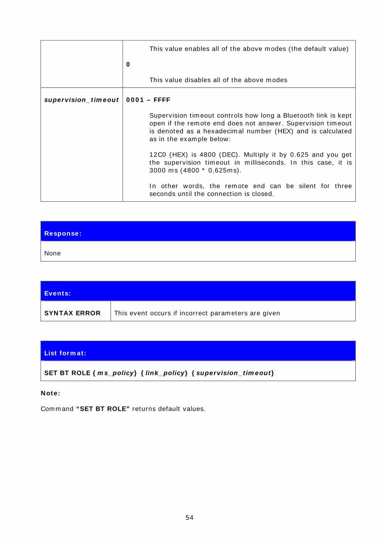
This command configures or displays the local device’s role configuration. With the “SET BT ROLE” command, iWRAP’s master-slave behavior can be configured. This command can also be used to set the supervision timeout and link policy.
6.10.1 Syntax
Synopsis:
SET BT ROLE {ms_policy} {link_policy} {supervision_timeout}
Description:
ms_policy This parameter defines how the master-slave policy works.
0
This value allows master-slave switch when calling, but iWRAP does not request it when answering (default value).
1
This value allows master-slave switch when calling, and iWRAP requests it when answering.
2
If this value is set, master-slave switch is not allowed when calling, but it is requested for when answering.
link_policy This bitmask controls the link policy modes. It is represented in a hexadecimal format.
Bit 1
If this bit is set, Role switch is enabled
Bit 2
If this bit is set, Hold mode is enabled
Bit 3
If this bit is set, Sniff mode is enabled
Bit 4
If this bit is set, Park state is enabled
F
54
This value enables all of the above modes (the default value)
0
This value disables all of the above modes
supervision_timeout 0001 – FFFF
Supervision timeout controls how long a Bluetooth link is kept open if the remote end does not answer. Supervision timeout is denoted as a hexadecimal number (HEX) and is calculated as in the example below:
12C0 (HEX) is 4800 (DEC). Multiply it by 0.625 and you get the supervision timeout in milliseconds. In this case, it is 3000 ms (4800 * 0,625ms).
In other words, the remote end can be silent for three seconds until the connection is closed.
Response:
None
Events:
SYNTAX ERROR This event occurs if incorrect parameters are given
List format:
SET BT ROLE {ms_policy} {link_policy} {supervision_timeout}
Note:
Command “SET BT ROLE” returns default values.

55
6.11 SET BT SNIFF
This command enables automatic sniff mode for Bluetooth connections. Notice that remote devices may not support sniff.
6.11.1 Syntax
Synopsis:
SET BT SNIFF {max}{min} [{attempt} {timeout}]
or
SET BT SNIFF {avg}
Description:
max Maximum acceptable interval in milliseconds
Range: 0x0002 to 0xFFFE; only even values are valid
Mandatory Range: 0x0006 to 0x0540
Time = N * 0.625 msec
Time Range: 1.25 msec to 40.9 sec
min Minimum acceptable interval in milliseconds
Range: 0x0002 to 0xFFFE; only even values are valid
Mandatory Range: 0x0006 to 0x0540
Time = N * 0.625 msec
Time Range: 1.25 msec to 40.9 sec
avg Average value in milliseconds. You can use this as a shortcut for easier sniff setting.
attempt Number of Baseband receive slots for sniff attempt.
Length = N* 1.25 msec
Range for N: 0x0001 – 0x7FFF
Time Range: 0.625msec - 40.9 Seconds
Mandatory Range for Controller: 1 to Tsniff/2
timeout Number of Baseband receive slots for sniff timeout.

56
Length = N * 1.25 msec
Range for N: 0x0000 – 0x7FFF
Time Range: 0 msec - 40.9 Seconds
Mandatory Range for Controller: 0 to 0x0028
Response:
None
Events:
SYNTAX ERROR This event occurs if incorrect parameters are given
List format:
SET BT SNIFF {max}{min} {attempt} {timeout}
Note:
“SET BT SNIFF” disables automatic sniff mode (default settings).
57
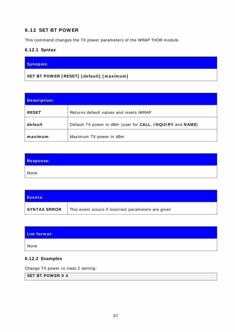
6.12 SET BT POWER
This command changes the TX power parameters of the WRAP THOR module.
6.12.1 Syntax
Synopsis:
SET BT POWER [RESET] [default] [maximum]
Description:
RESET Returns default values and resets iWRAP
default Default TX power in dBm (user for CALL, INQUIRY and NAME)
maximum Maximum TX power in dBm
Response:
None
Events:
SYNTAX ERROR This event occurs if incorrect parameters are given
List format:
None
6.12.2 Examples
Change TX power to class 2 setting:
SET BT POWER 0 4
58
Note:
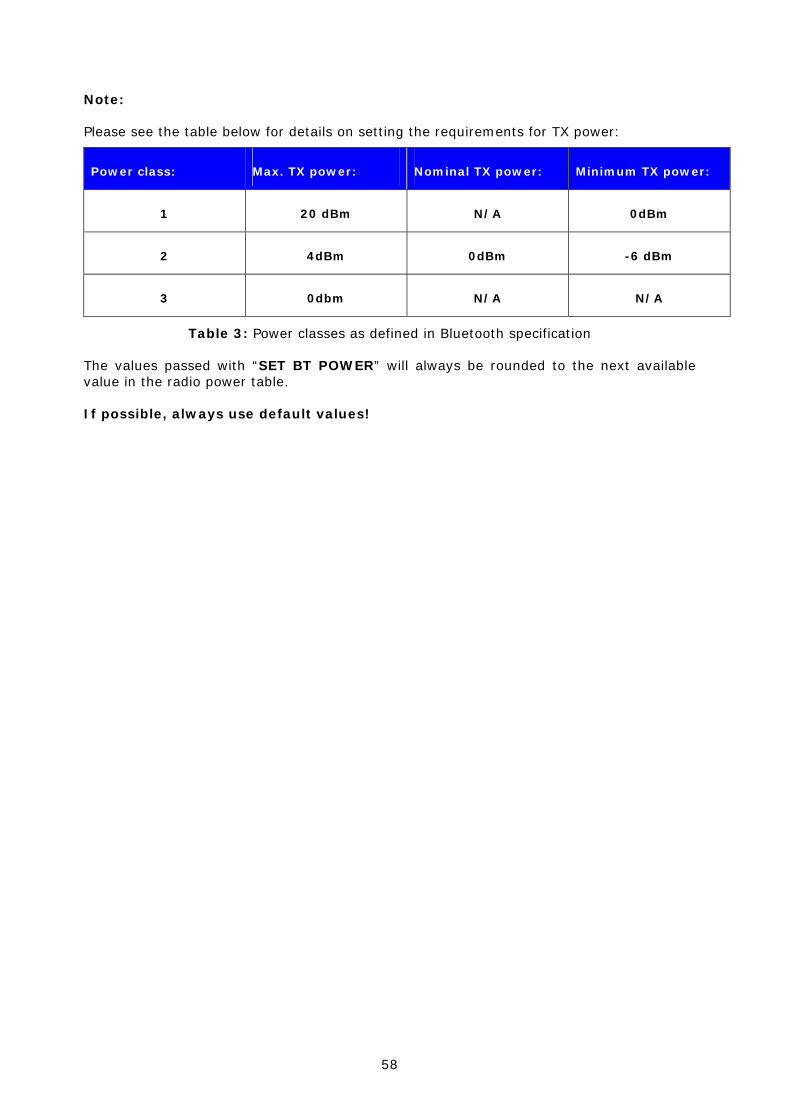
Please see the table below for details on setting the requirements for TX power:
Power class: Max. TX power: Nominal TX power: Minimum TX power:
1 20 dBm N/A 0dBm
2 4dBm 0dBm -6 dBm
3 0dbm N/A N/A
Table 3: Power classes as defined in Bluetooth specification
The values passed with “SET BT POWER” will always be rounded to the next available value in the radio power table.
If possible, always use default values!

59
6.13 SET CONTROL AUTOCALL
SET CONTROL AUTOCALL enables or disables the AUTOCALL functionality in iWRAP.
When the AUTOCALL feature is enabled, iWRAP tries to form a connection with a paired (see “SET BT PAIR”) device until the connection is established. If the connection is lost or closed, iWRAP tries to reopen it.
If there are several paired devices in iWRAP memory, an inquiry (transparent to the user) is made and the first paired device found is connected.
6.13.1 Syntax
Synopsis:
SET CONTROL AUTOCALL {target} {timeout}
Description:
target RFCOMM target for automatic connection
channel
RFCOMM channel number
Format xxxx (HEX)
uuid16
16-bit UUID for searching the channel
Format xxxx (HEX)
uuid32
32-bit UUID for searching the channel
Format xxxxxxxx (HEX)
uuid128
128-bit UUID for searching the channel.
Format xxxxxxxx-xxxx-xxxx-xxxx-xxxxxxxxxxxx (HEX)
timeout Timeout between calls (in milliseconds)
60
Response:
None
Events:
SYNTAX ERROR This event occurs if incorrect parameters are given
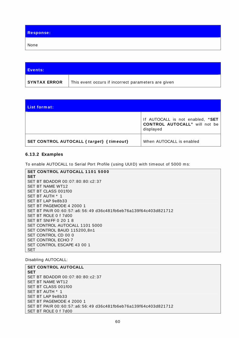
List format:
If AUTOCALL is not enabled, “SET CONTROL AUTOCALL” will not be displayed
SET CONTROL AUTOCALL {target} {timeout} When AUTOCALL is enabled
6.13.2 Examples
To enable AUTOCALL to Serial Port Profile (using UUID) with timeout of 5000 ms:
SET CONTROL AUTOCALL 1101 5000 SET SET BT BDADDR 00:07:80:80:c2:37 SET BT NAME WT12 SET BT CLASS 001f00 SET BT AUTH * 1 SET BT LAP 9e8b33 SET BT PAGEMODE 4 2000 1 SET BT PAIR 00:60:57:a6:56:49 d36c481fb6eb76a139f64c403d821712 SET BT ROLE 0 f 7d00 SET BT SNIFF 0 20 1 8 SET CONTROL AUTOCALL 1101 5000 SET CONTROL BAUD 115200,8n1 SET CONTROL CD 00 0 SET CONTROL ECHO 7 SET CONTROL ESCAPE 43 00 1 SET
Disabling AUTOCALL:
SET CONTROL AUTOCALL SET SET BT BDADDR 00:07:80:80:c2:37 SET BT NAME WT12 SET BT CLASS 001f00 SET BT AUTH * 1 SET BT LAP 9e8b33 SET BT PAGEMODE 4 2000 1 SET BT PAIR 00:60:57:a6:56:49 d36c481fb6eb76a139f64c403d821712 SET BT ROLE 0 f 7d00

61
SET BT SNIFF 0 20 1 8 SET CONTROL BAUD 115200,8n1 SET CONTROL CD 00 0 SET CONTROL ECHO 7 SET CONTROL ESCAPE 43 00 1 SET
Note:
Autocall can only be used with RFCOMM connections, not with SCO connections.
62
6.14 SET CONTROL BAUD
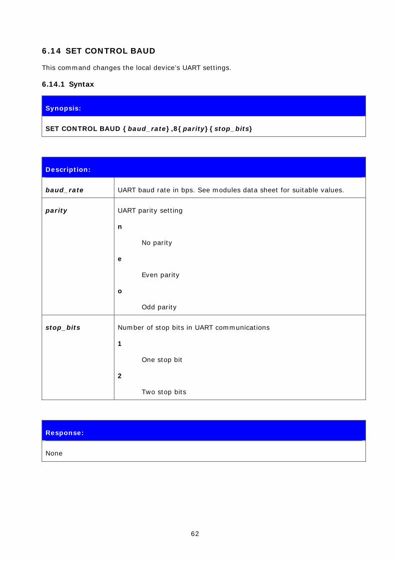
This command changes the local device’s UART settings.
6.14.1 Syntax
Synopsis:
SET CONTROL BAUD {baud_rate},8{parity}{stop_bits}
Description:
baud_rate UART baud rate in bps. See modules data sheet for suitable values.
parity UART parity setting
n
No parity
e
Even parity
o
Odd parity
stop_bits Number of stop bits in UART communications
1
One stop bit
2
Two stop bits
Response:
None
63
Events:
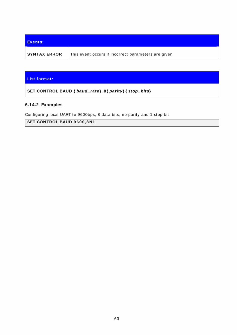
SYNTAX ERROR This event occurs if incorrect parameters are given
List format:
SET CONTROL BAUD {baud_rate},8{parity}{stop_bits}
6.14.2 Examples
Configuring local UART to 9600bps, 8 data bits, no parity and 1 stop bit
SET CONTROL BAUD 9600,8N1

64
6.15 SET CONTROL CD
This command enables or disables the carrier detect signal (CD) in iWRAP.
Carrier detect signal can be used to indicate that iWRAP has an active Bluetooth connection. With “SET CONTROL CD” command, one PIO line can be configured to act as a CD signal.
6.15.1 Syntax
Synopsis:
SET CONTROL CD {cd_mask} {datamode}
Description:
cd_mask This is a bit mask, which defines the GPIO lines used for CD signaling
For example, value 20 (HEX) must be used for PIO5.
20 (HEX) = 100000 (BIN)
For PIO6, the value is 40
40 (HEX) = 1000000 (BIN)
datamode This parameter defines how the carrier detect signal works.
0
CD signal is driven high if there are one or more connections.
1
CD signal is driven high only in data mode.
Events:
SYNTAX ERROR This event occurs if incorrect parameters are given
List format:
SET CONTROL CD {cd_mask} {datamode}
65
6.16 SET CONTROL CONFIG
6.16.1 Syntax
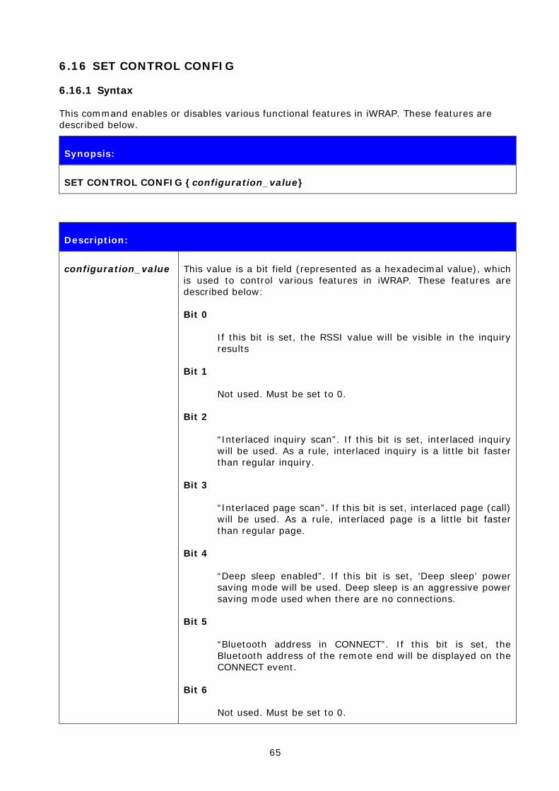
This command enables or disables various functional features in iWRAP. These features are described below.
Synopsis:
SET CONTROL CONFIG {configuration_value}
Description:
configuration_value This value is a bit field (represented as a hexadecimal value), which is used to control various features in iWRAP. These features are described below:
Bit 0
If this bit is set, the RSSI value will be visible in the inquiry results
Bit 1
Not used. Must be set to 0.
Bit 2
“Interlaced inquiry scan”. If this bit is set, interlaced inquiry will be used. As a rule, interlaced inquiry is a little bit faster than regular inquiry.
Bit 3
“Interlaced page scan”. If this bit is set, interlaced page (call) will be used. As a rule, interlaced page is a little bit faster than regular page.
Bit 4
“Deep sleep enabled”. If this bit is set, ‘Deep sleep’ power saving mode will be used. Deep sleep is an aggressive power saving mode used when there are no connections.
Bit 5
“Bluetooth address in CONNECT”. If this bit is set, the Bluetooth address of the remote end will be displayed on the CONNECT event.
Bit 6
Not used. Must be set to 0.
66
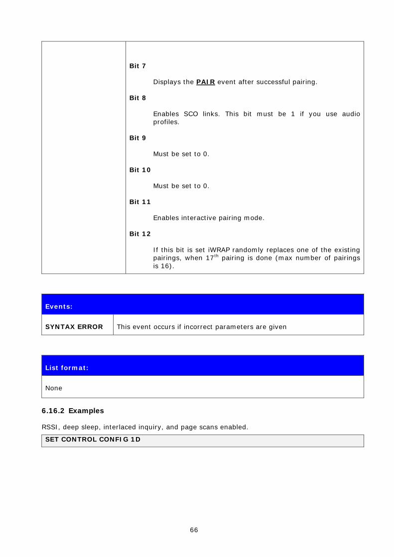
Bit 7
Displays the PAIR event after successful pairing.
Bit 8
Enables SCO links. This bit must be 1 if you use audio profiles.
Bit 9
Must be set to 0.
Bit 10
Must be set to 0.
Bit 11
Enables interactive pairing mode.
Bit 12
If this bit is set iWRAP randomly replaces one of the existing pairings, when 17th pairing is done (max number of pairings is 16).
Events:
SYNTAX ERROR This event occurs if incorrect parameters are given
List format:
None
6.16.2 Examples
RSSI, deep sleep, interlaced inquiry, and page scans enabled.
SET CONTROL CONFIG 1D

67
6.17 SET CONTROL ECHO
This command changes the echo mode of iWRAP.
6.17.1 Syntax
Synopsis:
SET CONTROL ECHO {echo_mask}
Description:
echo_mask Bit mask for controlling the display of echo and events
Bit 0
If this bit is set, the start-up banner is visible.
Bit 1
If this bit is set, characters are echoed back to client in command mode.
Bit 2
This bit indicates if set events are displayed in command mode.
Events:
SYNTAX ERROR This event occurs if incorrect parameters are given
List format:
SET CONTROL ECHO {echo_mask}
Warning!
If every bit is set off (value 0), it is quite impossible to know the iWRAP status.
If Bit 2 is set off, it is very hard to detect whether iWRAP is in command mode or in data mode. This can, however, be solved if one IO is used to indicate that iWRAP is in data mode (“SET CONTROL CD”).
68
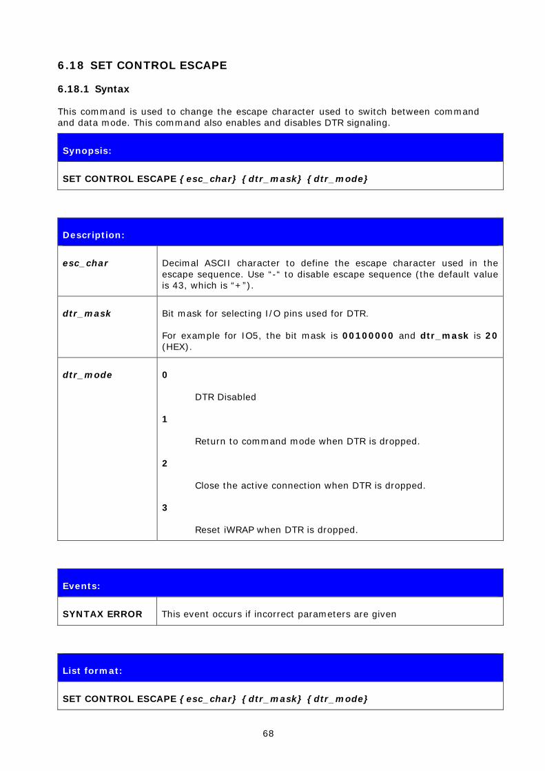
6.18 SET CONTROL ESCAPE
6.18.1 Syntax
This command is used to change the escape character used to switch between command and data mode. This command also enables and disables DTR signaling.
Synopsis:
SET CONTROL ESCAPE {esc_char} {dtr_mask} {dtr_mode}
Description:
esc_char Decimal ASCII character to define the escape character used in the escape sequence. Use “-“ to disable escape sequence (the default value is 43, which is “+”).
dtr_mask Bit mask for selecting I/O pins used for DTR.
For example for IO5, the bit mask is 00100000 and dtr_mask is 20 (HEX).
dtr_mode 0
DTR Disabled
1
Return to command mode when DTR is dropped.
2
Close the active connection when DTR is dropped.
3
Reset iWRAP when DTR is dropped.
Events:
SYNTAX ERROR This event occurs if incorrect parameters are given
List format:
SET CONTROL ESCAPE {esc_char} {dtr_mask} {dtr_mode}

69
6.18.2 Examples
How to disable default escape character “+” and configure DTR to PIO5.
SET CONTROL ESCAPE – 20 1
70
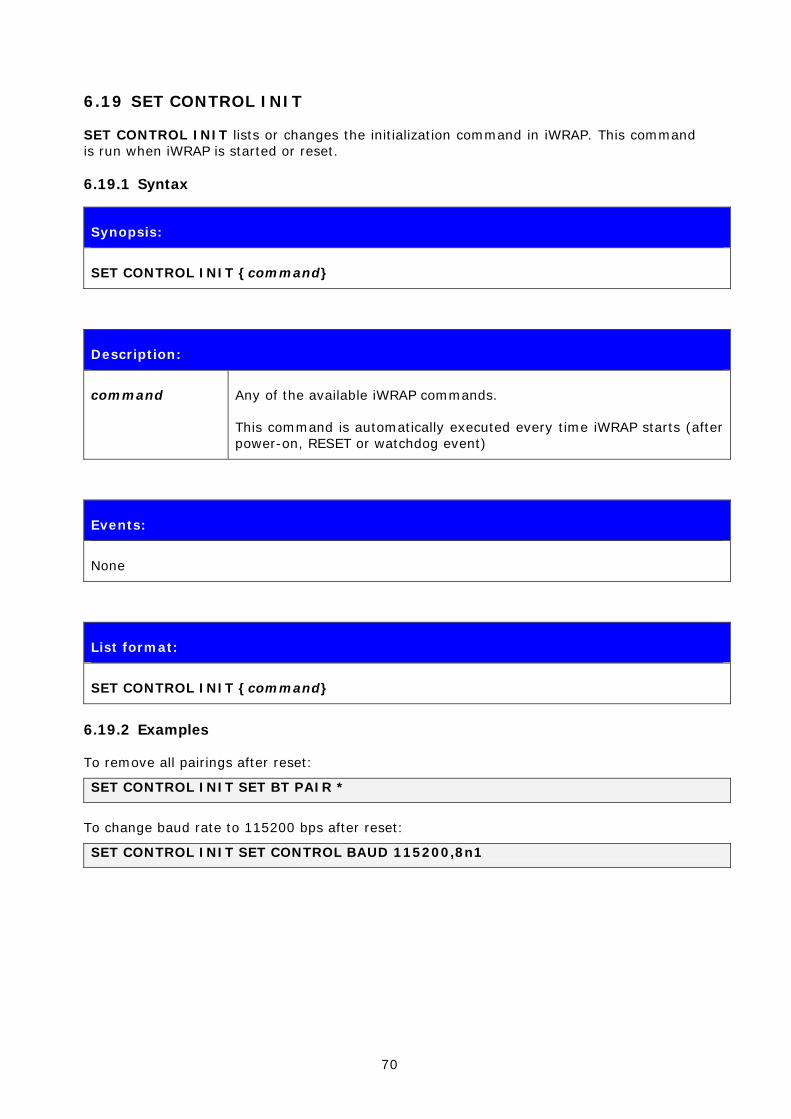
6.19 SET CONTROL INIT
SET CONTROL INIT lists or changes the initialization command in iWRAP. This command is run when iWRAP is started or reset.
6.19.1 Syntax
Synopsis:
SET CONTROL INIT {command}
Description:
command Any of the available iWRAP commands.
This command is automatically executed every time iWRAP starts (after power-on, RESET or watchdog event)
Events:
None
List format:
SET CONTROL INIT {command}
6.19.2 Examples
To remove all pairings after reset:
SET CONTROL INIT SET BT PAIR *
To change baud rate to 115200 bps after reset:
SET CONTROL INIT SET CONTROL BAUD 115200,8n1
71
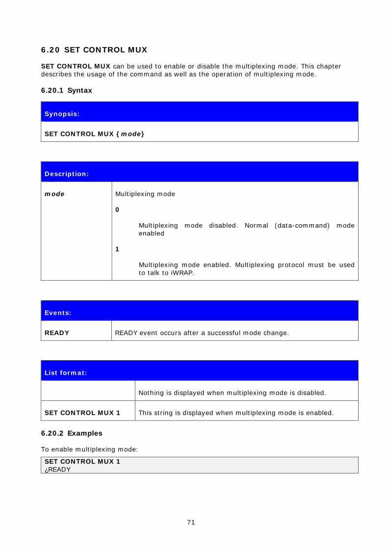
6.20 SET CONTROL MUX
SET CONTROL MUX can be used to enable or disable the multiplexing mode. This chapter describes the usage of the command as well as the operation of multiplexing mode.
6.20.1 Syntax
Synopsis:
SET CONTROL MUX {mode}
Description:
mode Multiplexing mode
0
Multiplexing mode disabled. Normal (data-command) mode enabled
1
Multiplexing mode enabled. Multiplexing protocol must be used to talk to iWRAP.
Events:
READY READY event occurs after a successful mode change.
List format:
Nothing is displayed when multiplexing mode is disabled.
SET CONTROL MUX 1 This string is displayed when multiplexing mode is enabled.
6.20.2 Examples
To enable multiplexing mode:
SET CONTROL MUX 1 ¿READY
72
Note:
When multiplexing mode is enabled, no ASCII commands can be given to iWRAP but the multiplexing protocol must be used. Multiplexing mode can be disabled by deleting PSKEY_USR3 with PSTool.
ASCII commands should not end with“\r\n” when multiplexing mode is in use.
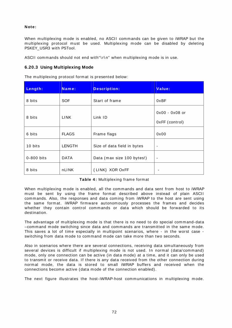
6.20.3 Using Multiplexing Mode
The multiplexing protocol format is presented below:
Length: Name: Description: Value:
8 bits SOF Start of frame 0xBF
8 bits LINK Link ID 0x00 - 0x08 or
0xFF (control)
6 bits FLAGS Frame flags 0x00
10 bits LENGTH Size of data field in bytes -
0-800 bits DATA Data (max size 100 bytes!) -
8 bits nLINK {LINK} XOR OxFF -
Table 4: Multiplexing frame format
When multiplexing mode is enabled, all the commands and data sent from host to iWRAP must be sent by using the frame format described above instead of plain ASCII commands. Also, the responses and data coming from iWRAP to the host are sent using the same format. iWRAP firmware autonomously processes the frames and decides whether they contain control commands or data which should be forwarded to its destination.
The advantage of multiplexing mode is that there is no need to do special command-data –command mode switching since data and commands are transmitted in the same mode. This saves a lot of time especially in multipoint scenarios, where - in the worst case - switching from data mode to command mode can take more than two seconds.
Also in scenarios where there are several connections, receiving data simultaneously from several devices is difficult if multiplexing mode is not used. In normal (data/command) mode, only one connection can be active (in data mode) at a time, and it can only be used to transmit or receive data. If there is any data received from the other connection during normal mode, the data is stored to small iWRAP buffers and received when the connections become active (data mode of the connection enabled).
The next figure illustrates the host-iWRAP-host communications in multiplexing mode.

73
Host UART
<0xBF> <0xFF> <0x00> <2> <AT> <0x00>
<0xBF> <0xFF> <0x00> <2> <OK> <0x00>
Figure 4: Host-iWRAP-Host communication
The figure below illustrates host-iWRAP-remote device communication when multiplexing mode is in use. The key thing is that the remote device does not need to know anything about the multiplexing communication and frame format, but it sees the connection as a standard Bluetooth connection.
Host UARTBluetooth link
<0xBF> <0x00> <0x00> <len> <Data> <0xFF>
<0xBF> <0x00> <0x00> <len> <Data> <0xFF>
Data
Data
Figure 5: Host-iWRAP-remote device communications
At the moment, four (4) simultaneous connections can be used in multiplexing mode.
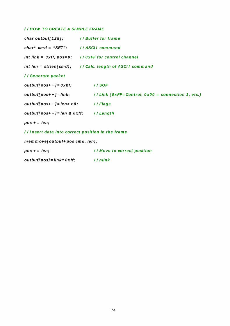
On the next page, there is a simple C-code example on how to create a simple multiplexing frame containing an iWRAP command.
74
//HOW TO CREATE A SIMPLE FRAME
char outbuf[128]; //Buffer for frame
char* cmd = “SET”; //ASCII command
int link = 0xff, pos=0; //0xFF for control channel
int len = strlen(cmd); //Calc. length of ASCII command
//Generate packet
outbuf[pos++]=0xbf; //SOF
outbuf[pos++]=link; //Link (0xFF=Control, 0x00 = connection 1, etc.)
outbuf[pos++]=len>>8; //Flags
outbuf[pos++]=len & 0xff; //Length
pos += len;
//Insert data into correct position in the frame
memmove(outbuf+pos cmd, len);
pos += len; //Move to correct position
outbuf[pos]=link^0xff; //nlink
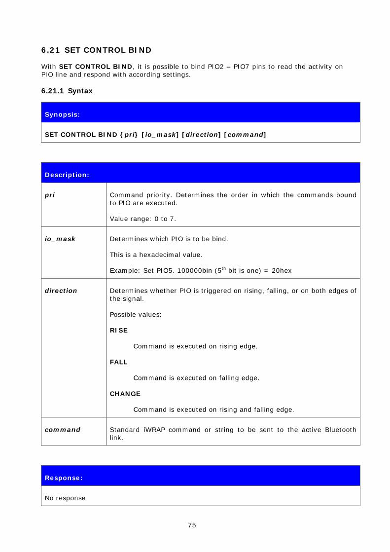
75
6.21 SET CONTROL BIND
With SET CONTROL BIND, it is possible to bind PIO2 – PIO7 pins to read the activity on PIO line and respond with according settings.
6.21.1 Syntax
Synopsis:
SET CONTROL BIND {pri} [io_mask] [direction] [command]
Description:
pri Command priority. Determines the order in which the commands bound to PIO are executed.
Value range: 0 to 7.
io_mask Determines which PIO is to be bind.
This is a hexadecimal value.
Example: Set PIO5. 100000bin (5th bit is one) = 20hex
direction Determines whether PIO is triggered on rising, falling, or on both edges of the signal.
Possible values:
RISE
Command is executed on rising edge.
FALL
Command is executed on falling edge.
CHANGE
Command is executed on rising and falling edge.
command Standard iWRAP command or string to be sent to the active Bluetooth link.
Response:
No response
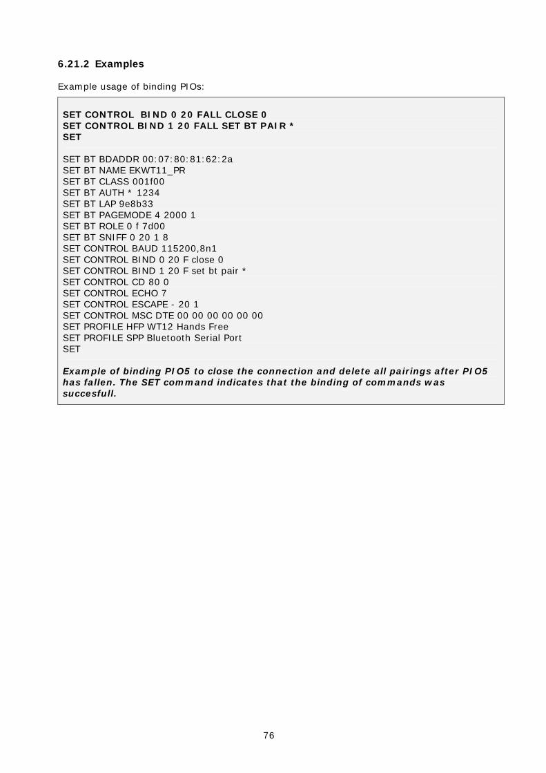
76
6.21.2 Examples
Example usage of binding PIOs:
SET CONTROL BIND 0 20 FALL CLOSE 0 SET CONTROL BIND 1 20 FALL SET BT PAIR * SET
SET BT BDADDR 00:07:80:81:62:2a SET BT NAME EKWT11_PR SET BT CLASS 001f00 SET BT AUTH * 1234 SET BT LAP 9e8b33 SET BT PAGEMODE 4 2000 1 SET BT ROLE 0 f 7d00 SET BT SNIFF 0 20 1 8 SET CONTROL BAUD 115200,8n1 SET CONTROL BIND 0 20 F close 0 SET CONTROL BIND 1 20 F set bt pair * SET CONTROL CD 80 0 SET CONTROL ECHO 7 SET CONTROL ESCAPE - 20 1 SET CONTROL MSC DTE 00 00 00 00 00 00 SET PROFILE HFP WT12 Hands Free SET PROFILE SPP Bluetooth Serial Port SET
Example of binding PIO5 to close the connection and delete all pairings after PIO5 has fallen. The SET command indicates that the binding of commands was succesfull.

77
6.22 SET CONTROL MSC
With iWRAP firmware, it is possible to transmit all the UART modem signals over the SPP (Serial Port Profile) Bluetooth link. The signals’ DSR, DTR, RTS, CTS, RI and DCD can be specified to PIO2-PIO7 on the WT12/WT11 and 2022-1 modules. The SET CONTROL MSC command is used to do this.
6.22.1 Syntax
Synopsis:
SET CONTROL MSC [[mode] [[DSR] [[DTR] [[RTS] [[CTS] [[RI] [DCD]]]]]]]
Description:
mode Mode of the device iWRAP connects to.
The mode can be:
DTE
or
DCE
NOTE:
DTE means that remote Bluetooth device is DTE (so iWRAP is DCE and device connected to iWRAP is DTE).
DSR Data Set Ready. Select PIO with a bitmask. See the note below on how to select the PIO.
DTR Data Terminal Ready. See the note below on how to select the PIO.
RTS Request To Send. See the note below on how to select the PIO.
CTS Clear To Send. See the note below on how to select the PIO.
RI Ring Indicator. See the note below on how to select the PIO.
DCD Data Carrier Detect. See the note below on how to select the PIO.
NOTE:
The PIO pin is selected with a bit mask. For example, if you want to use PIO3, you will then have a bit mask where the third bit is 1, that is, 1000. This bit mask value is then given in the command in hexadecimal format. 1000(bin) = 8(hex).
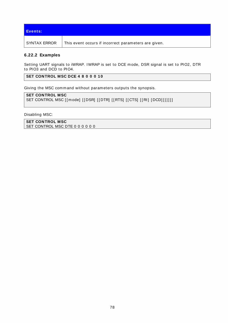
78
Events:
SYNTAX ERROR This event occurs if incorrect parameters are given.
6.22.2 Examples
Setting UART signals to iWRAP. IWRAP is set to DCE mode, DSR signal is set to PIO2, DTR to PIO3 and DCD to PIO4.
SET CONTROL MSC DCE 4 8 0 0 0 10
Giving the MSC command without parameters outputs the synopsis.
SET CONTROL MSC SET CONTROL MSC [[mode] [[DSR] [[DTR] [[RTS] [[CTS] [[RI] [DCD]]]]]]]
Disabling MSC:
SET CONTROL MSC SET CONTROL MSC DTE 0 0 0 0 0 0

79
7. SET {LINK_ID}
The following chapters describe all commands related to ‘SET {link_id}’. In general, you can use these commands to modify different parameters related to active Bluetooth connections, such as power saving, master-slave modes etc.
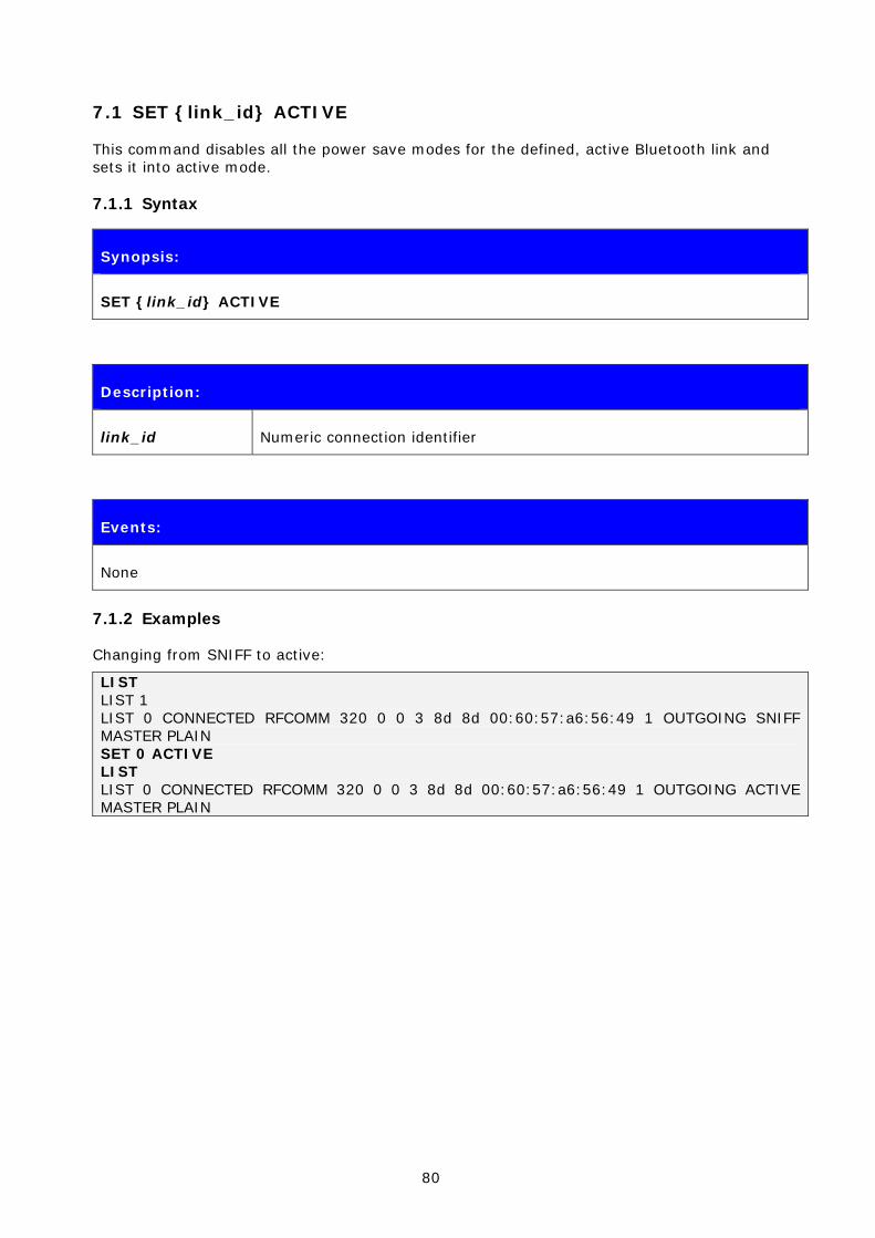
80
7.1 SET {link_id} ACTIVE
This command disables all the power save modes for the defined, active Bluetooth link and sets it into active mode.
7.1.1 Syntax
Synopsis:
SET {link_id} ACTIVE
Description:
link_id Numeric connection identifier
Events:
None
7.1.2 Examples
Changing from SNIFF to active:
LIST LIST 1 LIST 0 CONNECTED RFCOMM 320 0 0 3 8d 8d 00:60:57:a6:56:49 1 OUTGOING SNIFF MASTER PLAIN SET 0 ACTIVE LIST LIST 0 CONNECTED RFCOMM 320 0 0 3 8d 8d 00:60:57:a6:56:49 1 OUTGOING ACTIVE MASTER PLAIN

81
7.2 SET {link_id} MASTER
This command attempts to switch the link to Piconet master. Notice that this may not be allowed by the remote end.
7.2.1 Syntax
Synopsis:
SET {link_id} MASTER
Description:
link_id Numeric connection identifier
Events:
None
7.2.2 Examples
Changing from slave to master:
LIST LIST 1 LIST 0 CONNECTED RFCOMM 320 0 0 3 8d 8d 00:60:57:a6:56:49 1 OUTGOING ACTIVE SLAVE PLAIN SET 0 MASTER LIST LIST 0 CONNECTED RFCOMM 320 0 0 3 8d 8d 00:60:57:a6:56:49 1 OUTGOING ACTIVE MASTER PLAIN

82
7.3 SET {link_id} SLAVE
This command attempts to switch the link to Piconet slave. Notice that this may not be allowed by the remote end.
7.3.1 Syntax
Synopsis:
SET {link_id} SLAVE
Description:
link_id Numeric connection identifier
Events:
None

83
7.4 SET {link_id} PARK
This command attempts to enable PARK mode for the defined Bluetooth link. Whether this command is successful or not, depends on if the remote end allows park state to be used.
7.4.1 Syntax
Synopsis:
SET {link_id} PARK {max}{min}
or
SET {link_id} PARK {avg}
Description:
link_id Numeric connection identifier
max Maximum acceptable interval
min Minimum acceptable interval
avg Shortcut for easier PARK setting
Events:
None
7.4.2 Examples
Changing from active to PARK:
LIST LIST 1 LIST 0 CONNECTED RFCOMM 320 0 0 3 8d 8d 00:60:57:a6:56:49 1 OUTGOING ACTIVE MASTER PLAIN SET 0 PARK 1000 LIST LIST 0 CONNECTED RFCOMM 320 0 0 3 8d 8d 00:60:57:a6:56:49 1 OUTGOING PARK MASTER PLAIN
Note:
Refer to the Bluetooth specification for more information about PARK state and its usage.
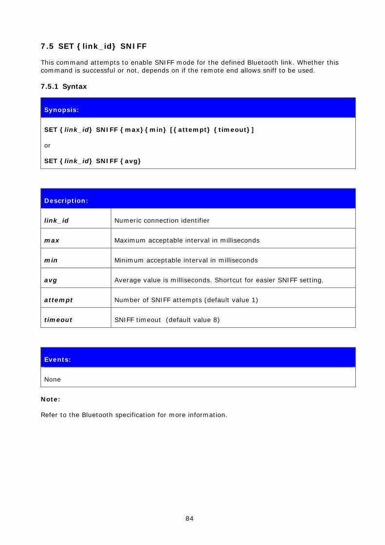
84
7.5 SET {link_id} SNIFF
This command attempts to enable SNIFF mode for the defined Bluetooth link. Whether this command is successful or not, depends on if the remote end allows sniff to be used.
7.5.1 Syntax
Synopsis:
SET {link_id} SNIFF {max}{min} [{attempt} {timeout}]
or
SET {link_id} SNIFF {avg}
Description:
link_id Numeric connection identifier
max Maximum acceptable interval in milliseconds
min Minimum acceptable interval in milliseconds
avg Average value is milliseconds. Shortcut for easier SNIFF setting.
attempt Number of SNIFF attempts (default value 1)
timeout SNIFF timeout (default value 8)
Events:
None
Note:
Refer to the Bluetooth specification for more information.

85
7.6 SET {link} MSC
With this command, it is possible to send 07.10 Modem Status Command to the remote device without having the signals actually connected to the module.
7.6.1 Syntax
Synopsis:
SET {link_id} MSC {status}
Description:
link_id Numeric connection identifier of the link where the modem status is to be sent.
status Status of the signals according to 07.10 standard.
Response:
No response
7.6.2 Examples
Example usage of sending MSC:
SET 0 MSC 8D
Normal MSC status was sent.
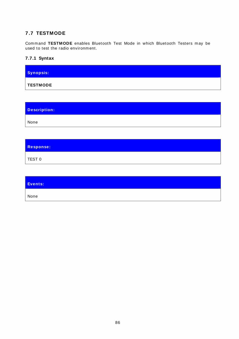
86
7.7 TESTMODE
Command TESTMODE enables Bluetooth Test Mode in which Bluetooth Testers may be used to test the radio environment.
7.7.1 Syntax
Synopsis:
TESTMODE
Description:
None
Response:
TEST 0
Events:
None

87
7.8 BER {link_id}
The BER command returns the Bit Error Rate of the link given as a parameter.
7.8.1 Syntax
Synopsis:
BER {link_id}
Description:
link_id Numeric connection identifier
Response:
BER {bd_addr} {ber}
bd_addr Bluetooth address of the remote device
ber Average Bit Error Rate on the link. Possible values are from 0.0000 to 100.0000.
Events:
None
7.8.2 Examples
Checking the Bit Error Rate of an active connection
LIST LIST 1 LIST 0 CONNECTED RFCOMM 320 0 0 3 8d 8d 00:60:57:a6:56:49 1 OUTGOING ACTIVE MASTER PLAIN BER 0 BER 00:60:57:a6:56:49 0.0103
Note:
Works only for BDR links.

88
7.9 RSSI {link_id}
The RSSI command returns the Receiver Signal Strength Indication of the link given as a parameter.
7.9.1 Syntax
Synopsis:
RSSI {link_id}
Description:
link_id Numeric connection identifier
Response:
RSSI {bd_addr} {rssi}
bd_addr Bluetooth address of the remote device
rssi Receiver Signal Strength Indication. Possible values are from +20 to -128.
20 = Good link
-128 = Poor link
Events:
None
7.9.2 Examples
Checking the Bit Error Rate of an active connection:
LIST LIST 1 LIST 0 CONNECTED RFCOMM 320 0 0 3 8d 8d 00:60:57:a6:56:49 1 OUTGOING ACTIVE MASTER PLAIN RSSI 0 RSSI 00:60:57:a6:56:49 -10

89
7.10 TXPOWER
The TXPOWER command can be used check the TX output power level of an active Bluetooth link.
7.10.1 Syntax
Synopsis:
TXPOWER {link_id}
Description:
link_id Numeric connection identifier
Response:
TXPOWER {bd_addr} {txpower}
bd_addr Bluetooth address of the remote device
Txpower User TX power level in dBm
Events:
None
7.10.2 Examples
Checking the TX power level of an active connection:
LIST LIST 1 LIST 0 CONNECTED RFCOMM 320 0 0 3 8d 8d 00:60:57:a6:56:49 1 OUTGOING ACTIVE MASTER PLAIN TXPOWER 0 TXPOWER 00:60:57:a6:56:49 3

90
7.11 SDP
The SDP command can be used to browse the available services on other Bluetooth devices.
7.11.1 Syntax
Synopsis:
SDP {bd_addr} {uuid}
Description:
bd_addr Bluetooth address of the remote device
Uuid Service to look for
UUID “1002” stands for root and returns all the services the remote device supports.
Response:
SDP {bd_addr} < I SERVICENAME S “service_name” > < I PROTOCOLDESCRIPTORLIST < < U L2CAP > < U RFCOMM I channel > > >
SDP
bd_addr Bluetooth address of the remote device
service name Name of the service. For example “Serial Port Profile”
channel RFCOMM channel for the service
Events:
None
7.11.2 Examples
How to look for the SPP service:
SDP 00:07:80:80:52:15 1101 SDP 00:07:80:80:52:15 < I SERVICENAME S "Bluetooth Serial Port" > < I PROTOCOLDE

91
SCRIPTORLIST < < U L2CAP > < U RFCOMM I 01 > > > SDP
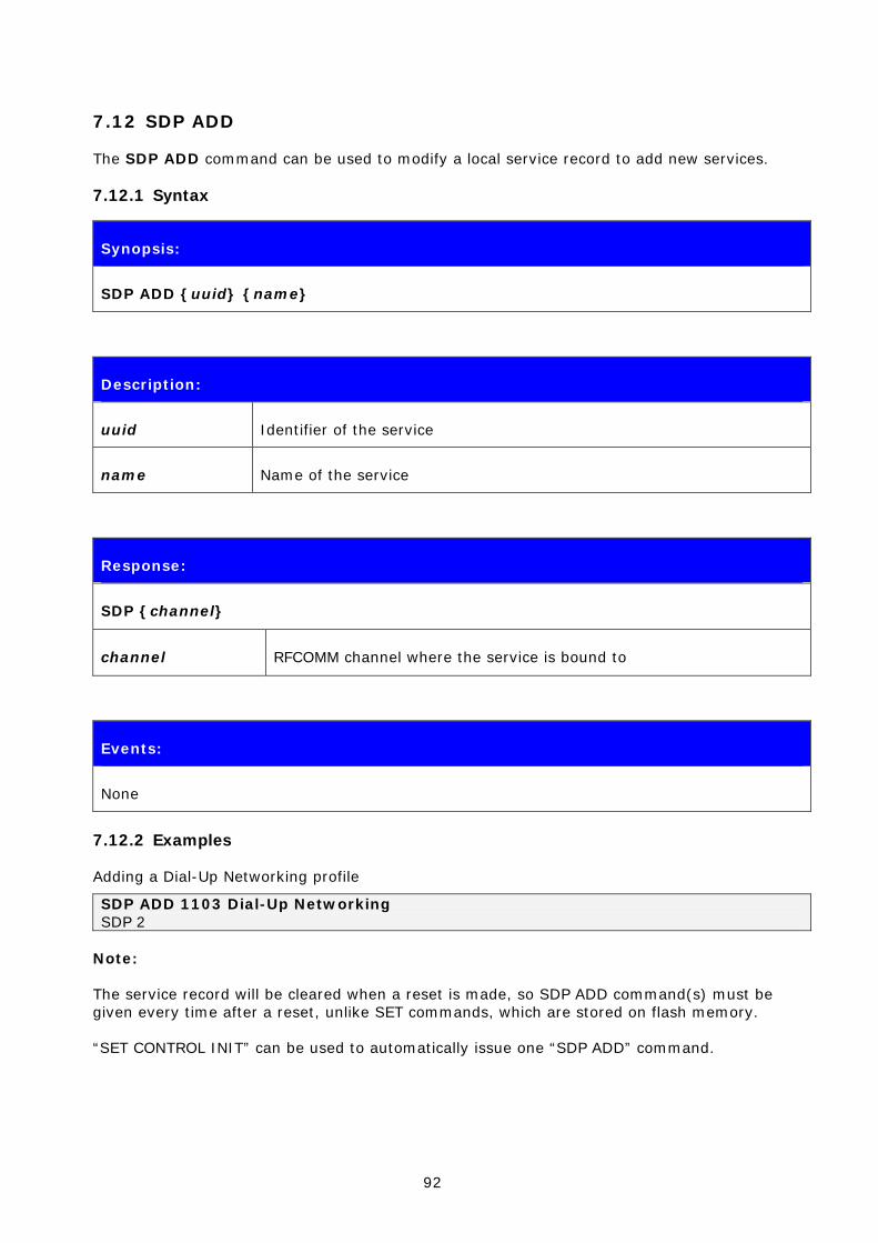
92
7.12 SDP ADD
The SDP ADD command can be used to modify a local service record to add new services.
7.12.1 Syntax
Synopsis:
SDP ADD {uuid} {name}
Description:
uuid Identifier of the service
name Name of the service
Response:
SDP {channel}
channel RFCOMM channel where the service is bound to
Events:
None
7.12.2 Examples
Adding a Dial-Up Networking profile
SDP ADD 1103 Dial-Up Networking SDP 2
Note:
The service record will be cleared when a reset is made, so SDP ADD command(s) must be given every time after a reset, unlike SET commands, which are stored on flash memory.
“SET CONTROL INIT” can be used to automatically issue one “SDP ADD” command.
93
7.13 SLEEP
The SLEEP command will force deep sleep on. After issuing this command, the module will enter deep sleep until a Bluetooth connection is received or something is received from the UART interface in command mode. The SLEEP command will also work when there are one or more active connections and iWRAP is in command mode.
Deep sleep is an aggressive power saving mode for WRAP THOR modules.
7.13.1 Syntax
Synopsis:
SLEEP
Description:
None.
Response:
None
Events:
None
Note:
Refer to power consumption documents for more information about power consumption in deep sleep mode.

94
7.14 SCO ENABLE
The SCO ENABLE command is needed before any SCO (audio) connections can be used
7.14.1 Syntax
Synopsis:
SCO ENABLE
Description:
None
Response:
None
Events:
None
Note:
The SCO ENABLE command must be given every time after reset; it is not stored on flash memory.
“SET CONTROL INIT” can be used to automatically issue one “SCO ENABLE” command.

95
7.15 SCO OPEN
The SCO OPEN command is used to open the actual SCO connection. An existing RFCOMM connection is needed before SCO OPEN can be issued.
7.15.1 Syntax
Synopsis:
SCO OPEN {link_id}
Description:
link_id Numeric connection identifier
Response:
None
Response:
None
Events:
CONNECT If SCO connection was opened successfully
NO_CARRIER If connection opening failed
Note:
The SCO ENABLE command must be given before the SCO OPEN command can be used.

96
7.15.2 Examples
Creating an SCO connection to another iWRAP device:
SCO ENABLE CALL 00:07:80:80:52:27 1 RFCOMM CALL 0 CONNECT 0 RFCOMM 1 [+++] SCO OPEN 0 CONNECT 1 SCO

97
7.16 BOOT
The BOOT command is used to change the module settings. After issuing this command, the module will enter the selected mode. The modes are explained in chapter 8.3. After resetting the module, it will boot in iWRAP mode again.
7.16.1 Syntax
Synopsis:
BOOT [boot_mode]
Description:
boot_mode 0000
iWRAP
0001
HCI, BCSP, 115800,8n1
0003
HCI, USB
0004
HCI, H4, 115200,8n1
Response:
No response
7.16.2 Examples
BOOT 1 �Ò�¯WWUo`À �Ò�¯WWUo`À �Ò�¯WWUo`À �Ò�¯WWUo`À �Ò�¯WWUo `À Example of changing the module to HCI BCSP 115200 with the BOOT command. After resetting the module, iWRAP becomes active.

98
7.17 ECHO
The ECHO command sends a specified string of characters to the active link specified by the ‘link_id’ parameter. This command can be used, for example, with command SET CONTROL BIND to send an indication of activity over a Bluetooth link.
7.17.1 Syntax
Synopsis:
ECHO {link_id} [string]
Description:
link_id Numeric connection identifier
string User-determined string of characters
If “%p” is used as a value, iWRAP echos the status of local GPIO pins
Response:
No response
Events:
None
7.17.2 Examples
ECHO 0 WT12_DATA_1 On the other device UART receive: WT12_DATA_1
99
7.18 PING {link_id}
The PING command sends a Bluetooth test packet to the other device, which sends the packet back and the round trip time of the packet is shown.
7.18.1 Syntax
Synopsis:
PING {link_id}
Description:
link_id Numeric connection identifier
Response:
RSSI {bd_addr} {round trip time}
bd_addr Bluetooth address of the remote device
Round trip time Round trip time of the packet
Events:
None
7.18.2 Examples
Checking the round trip time:
PING 0 PING 00:07:80:80:c3:4a 42 Round trip time is 42ms in this case.
100
7.19 TEST
The TEST command is used to give radio test commands to iWRAP. The commands are the same that can be given by using CSR BlueTest software (downloadable from www.bluegiga.com/techforum). See the Performance Measurement Guide for instructions on using radio tests.
7.19.1 Syntax
Synopsis:
TEST {mode} [mode_specific_parameters]
Description:
mode &
mode_specific_parameters
RF Test mode
Supported test modes are:
PAUSE
Pause halts the current test and stops any radio activity.
TXSTART {lo_freq} {level} {mod_freq}
Enables the transmitter in continuous transmission at a designated frequency (lo_freq) with a designated output power (level) and designated tone modulation frequency (mod_freq).
lo_freq range: 2402 – 2480 (MHz)
level range: 0 – 63
mod_freq range: 0 – 32767 (recommended values 0 or 256)
TXDATA1 {lo_freq} {level}
Enables the transmitter with a designated frequency (lo_freq) and output power (level). Payload is PRBS9 data. In this mode, the receiver is not operating.
TXDATA2 {cc} {level}
Enables the transmitter with a simplified hop sequence designated by country code {cc} and output power {level}. Payload is PRBS9 data. In this mode, the receiver is not operating.
Related test spec name: TRM/CA/01/C (output
101
power), TRM/CA/02/C (power density).
cc range: 0 – 3 (default = 0)
RXSTART {lo_freq} {highside} {attn}
Enables the receiver in continuous reception at a designated frequency (lo_freq) with a choice of low or high side modulation (highside) and with designated attenuation setting (attn).
highside range: 0 or 1 (default = false = 0)
attn: range: 0 – 15
DEEPSLEEP
Puts the module into deep-sleep after a delay of half a second until woken by a reset or activity on UART.
PCMLB {pcm_mode}
Sets the PCM to loop back mode, where the data read from PCM input is output again on the PCM output.
If pcm_mode = 0, module is slave in normal 4-wire configuration
If pcm_mode = 1, module is master in normal 4-wire configuration
If pcm_mode = 2, module is master in Manchester encoded 2-wire configuration
PCMEXTLB {pcm_mode}
Sets the PCM to external loop back mode, whereby the data written to PCM output is read again on the input. Check is made that the data read back is the same as that written.
The external loop back may be a simple wire.
LOOPBACK {lo_freq} {level}
Receives data on set frequency lo_freq for data packets and then retransmits this data on the same channel at output power level.
CFGXTALFTRIM {xtal_ftrim}
This command can be used to set the crystal frequency trim value directly from iWRAP. This is not a permanent setting!
xtal_ftrim range: 0 – 63
PCMTONE {freq} {ampl} {dc}
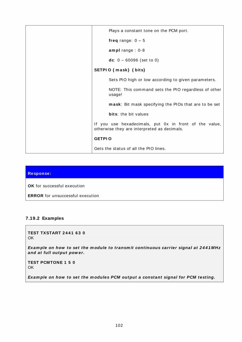
102
Plays a constant tone on the PCM port.
freq range: 0 – 5
ampl range : 0-8
dc: 0 – 60096 (set to 0)
SETPIO {mask} {bits}
Sets PIO high or low according to given parameters.
NOTE: This command sets the PIO regardless of other usage!
mask: Bit mask specifying the PIOs that are to be set
bits: the bit values
If you use hexadecimals, put 0x in front of the value, otherwise they are interpreted as decimals.
GETPIO
Gets the status of all the PIO lines.
Description:
Response:
OK for successful execution
ERROR for unsuccessful execution
7.19.2 Examples
TEST TXSTART 2441 63 0 OK
Example on how to set the module to transmit continuous carrier signal at 2441MHz and at full output power.
TEST PCMTONE 1 5 0 OK
Example on how to set the modules PCM output a constant signal for PCM testing.
103
8. IWRAP EVENTS
Events are a mechanism that iWRAP uses to notify the user for completed commands, incoming connections, and so on.
If iWRAP is in data mode (data is being transmitted and no multiplexing mode is used) the only possible event is NO CARRIER indicating that connection was closed or lost.
Note:
• iWRAP is designed so that unwanted events can be safely ignored. Events CONNECT, NO CARRIER and RING change the mode of operation and therefore they cannot be ignored.
• Events can be masked away by removing Bit 2 from command SET CONTROL ECHO.
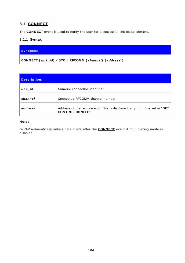
104
8.1 CONNECT
The CONNECT event is used to notify the user for a successful link establishment.
8.1.1 Syntax
Synopsis:
CONNECT {link_id} {SCO | RFCOMM {channel} [address]}
Description:
link_id Numeric connection identifier
channel Connected RFCOMM channel number
address Address of the remote end. This is displayed only if bit 5 is set in “SET CONTROL CONFIG”.
Note:
iWRAP automatically enters data mode after the CONNECT event if multiplexing mode is disabled.
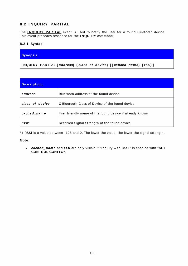
105
8.2 INQUIRY_PARTIAL
The INQUIRY_PARTIAL event is used to notify the user for a found Bluetooth device. This event precedes response for the INQUIRY command.
8.2.1 Syntax
Synopsis:
INQUIRY_PARTIAL {address} {class_of_device} [{cahced_name} {rssi}]
Description:
address Bluetooth address of the found device
class_of_device C Bluetooth Class of Device of the found device
cached_name User friendly name of the found device if already known
rssi* Received Signal Strength of the found device
*) RSSI is a value between -128 and 0. The lower the value, the lower the signal strength.
Note:
• cached_name and rssi are only visible if “Inquiry with RSSI” is enabled with “SET CONTROL CONFIG”.
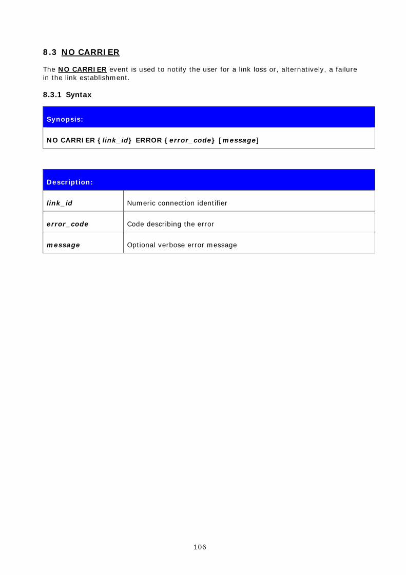
106
8.3 NO CARRIER
The NO CARRIER event is used to notify the user for a link loss or, alternatively, a failure in the link establishment.
8.3.1 Syntax
Synopsis:
NO CARRIER {link_id} ERROR {error_code} [message]
Description:
link_id Numeric connection identifier
error_code Code describing the error
message Optional verbose error message
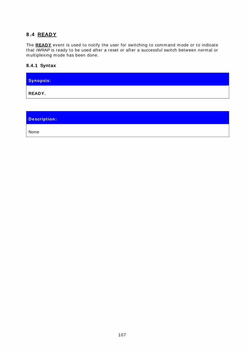
107
8.4 READY
The READY event is used to notify the user for switching to command mode or to indicate that iWRAP is ready to be used after a reset or after a successful switch between normal or multiplexing mode has been done.
8.4.1 Syntax
Synopsis:
READY.
Description:
None
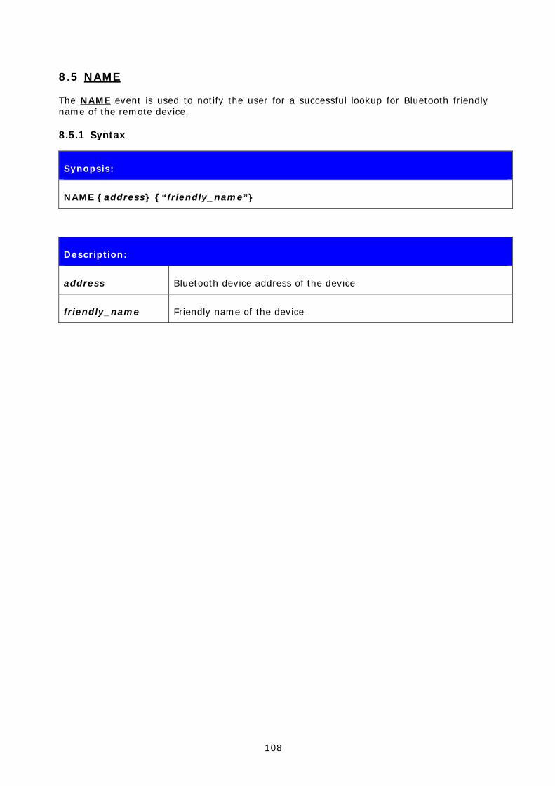
108
8.5 NAME
The NAME event is used to notify the user for a successful lookup for Bluetooth friendly name of the remote device.
8.5.1 Syntax
Synopsis:
NAME {address} {“friendly_name”}
Description:
address Bluetooth device address of the device
friendly_name Friendly name of the device

109
8.6 NAME ERROR
The NAME ERROR event is used to notify the user for a Bluetooth friendly name lookup failure.
8.6.1 Syntax
Synopsis:
NAME ERROR {error_code} {address} [message]
Description:
error_code Code describing the error
address Bluetooth address of the device
message Optional verbose error message

110
8.7 PAIR
The PAIR event is used to notify the user for a successful pairing.
8.7.1 Syntax
Synopsis:
PAIR {address} {key_type} {link_key}
Description:
address Bluetooth device address of the paired device
key_type Type of link key
0
Combination key
1
Local unit key
2
Remote unit key
ff
Unknown key
link_key Link key shared between the local and the paired device
Note:
The PAIR event is enabled or disabled with the “SET CONTROL CONFIG” command.
If the PAIR event is enabled and pairing is done, the event will also be shown during the CALL procedure and also before the RING event.

111
8.8 RING
The RING event is used to notify the user for an incoming connection. Incoming connections are only accepted if there is no existing links.
8.8.1 Syntax
Synopsis:
RING {link_id} {address} {SCO | {channel} RFCOMM}
Description:
link_id Numeric connection identifier
address Bluetooth device address of the device
channel Local RFCOMM or SCO channel

112
8.9 SYNTAX ERROR
SYNTAX ERROR is not an actual event, but an error message describing a faulty typed command or an error in command parameters.
8.9.1 Syntax
Synopsis:
SYNTAX ERROR

113
8.10 AUTH
AUTH event indicates that someone is trying to pair with iWRAP.
8.10.1 Syntax
Synopsis:
AUTH {bd_addr}?
Description:
bd_addr Bluetooth device address of the remote device
The AUTH event occurs only if interactive pairing is enabled with “SET CONTROL CONFIG” command.

114
9. IWRAP ERROR MESSAGES
This chapter briefly presents the iWRAP error messages.
9.1 HCI Errors
HCI errors start with code: 0x100
ERROR MESSAGE CODE Explanation
HCI_SUCCESS 0x00 Success
HCI_ERROR_ILLEGAL_COMMAND 0x01 Unknown HCI command
HCI_ERROR_NO_CONNECTION 0x02 Unknown connection identifier
HCI_ERROR_HARDWARE_FAIL 0x03 Hardware Failure
HCI_ERROR_PAGE_TIMEOUT 0x04 Page timeout
HCI_ERROR_AUTH_FAIL 0x05 Authentication failure
HCI_ERROR_KEY_MISSING 0x06 PIN or key missing
HCI_ERROR_MEMORY_FULL 0x07 Memory capacity exceeded
HCI_ERROR_CONN_TIMEOUT 0x08 Connection timeout
HCI_ERROR_MAX_NR_OF_CONNS 0x09 Connection Limit Exceeded
HCI_ERROR_MAX_NR_OF_SCO 0x0a Synchronous connection limit to a device exceeded
HCI_ERROR_MAX_NR_OF_ACL 0x0b ACL Connection Already Exists
HCI_ERROR_COMMAND_DISALLOWED 0x0c Command Disallowed
HCI_ERROR_REJ_BY_REMOTE_NO_RES 0x0d Connection Rejected due to Limited Resources
HCI_ERROR_REJ_BY_REMOTE_SEC 0x0e Connection Rejected Due To Security Reasons
HCI_ERROR_REJ_BY_REMOTE_PERS 0x0f Connection Rejected due to Unacceptable BD_ADDR
HCI_ERROR_HOST_TIMEOUT 0x10 Connection Accept Timeout Exceeded

115
HCI_ERROR_UNSUPPORTED_FEATURE 0x11 Unsupported Feature or Parameter Value
HCI_ERROR_ILLEGAL_FORMAT 0x12 Invalid HCI Command Parameter
HCI_ERROR_OETC_USER 0x13 Remote User Terminated Connection
HCI_ERROR_OETC_LOW_RESOURCE 0x14 Remote Device Terminated Connection due to Low Resources
HCI_ERROR_OETC_POWERING_OFF 0x15 Remote Device Terminated Connection due to Power Off
HCI_ERROR_CONN_TERM_LOCAL_HOST 0x16 Connection Terminated By Local Host
HCI_ERROR_AUTH_REPEATED 0x17 Repeated Attempts
HCI_ERROR_PAIRING_NOT_ALLOWED 0x18 Pairing Not Allowed
HCI_ERROR_UNKNOWN_LMP_PDU 0x19 Unknown LMP PDU
HCI_ERROR_UNSUPPORTED_REM_FEATURE 0x1a Unsupported Remote Feature / Unsupported LMP Feature
HCI_ERROR_SCO_OFFSET_REJECTED 0x1b SCO Offset Rejected
HCI_ERROR_SCO_INTERVAL_REJECTED 0x1c SCO Interval Rejected
HCI_ERROR_SCO_AIR_MODE_REJECTED 0x1d SCO Air Mode Rejected
HCI_ERROR_INVALID_LMP_PARAMETERS 0x1e Invalid LMP Parameters
HCI_ERROR_UNSPECIFIED 0x1f Unspecified Error
HCI_ERROR_UNSUPP_LMP_PARAM 0x20 Unsupported LMP Parameter Value
HCI_ERROR_ROLE_CHANGE_NOT_ALLOWED 0x21 Role Change Not Allowed
HCI_ERROR_LMP_RESPONSE_TIMEOUT 0x22 LMP Response Timeout
HCI_ERROR_LMP_TRANSACTION_COLLISION 0x23 LMP Error Transaction Collision

116
HCI_ERROR_LMP_PDU_NOT_ALLOWED 0x24 LMP PDU Not Allowed
HCI_ERROR_ENC_MODE_NOT_ACCEPTABLE 0x25 Encryption Mode Not Acceptable
HCI_ERROR_UNIT_KEY_USED 0x26 Link Key Can Not be Changed
HCI_ERROR_QOS_NOT_SUPPORTED 0x27 Requested QoS Not Supported
HCI_ERROR_INSTANT_PASSED 0x28 Instant Passed
HCI_ERROR_PAIR_UNIT_KEY_NO_SUPPORT 0x29 Pairing With Unit Key Not Supported
Table 5: HCI errors
Please see Bluetooth 2.0+EDR core specification page 493 for more information about error codes.
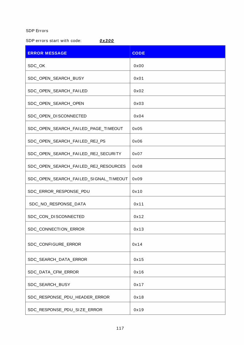
117
SDP Errors
SDP errors start with code: 0x300
ERROR MESSAGE CODE
SDC_OK 0x00
SDC_OPEN_SEARCH_BUSY 0x01
SDC_OPEN_SEARCH_FAILED 0x02
SDC_OPEN_SEARCH_OPEN 0x03
SDC_OPEN_DISCONNECTED 0x04
SDC_OPEN_SEARCH_FAILED_PAGE_TIMEOUT 0x05
SDC_OPEN_SEARCH_FAILED_REJ_PS 0x06
SDC_OPEN_SEARCH_FAILED_REJ_SECURITY 0x07
SDC_OPEN_SEARCH_FAILED_REJ_RESOURCES 0x08
SDC_OPEN_SEARCH_FAILED_SIGNAL_TIMEOUT 0x09
SDC_ERROR_RESPONSE_PDU 0x10
SDC_NO_RESPONSE_DATA 0x11
SDC_CON_DISCONNECTED 0x12
SDC_CONNECTION_ERROR 0x13
SDC_CONFIGURE_ERROR 0x14
SDC_SEARCH_DATA_ERROR 0x15
SDC_DATA_CFM_ERROR 0x16
SDC_SEARCH_BUSY 0x17
SDC_RESPONSE_PDU_HEADER_ERROR 0x18
SDC_RESPONSE_PDU_SIZE_ERROR 0x19

118
SDC_RESPONSE_TIMEOUT_ERROR 0x1a
SDC_SEARCH_SIZE_TOO_BIG 0x1b
SDC_RESPONSE_OUT_OF_MEMORY 0x1c
SDC_RESPONSE_TERMINATED 0x1d
Table 6: SDP errors

119
9.2 RFCOMM Errors
RFCOMM errors start with code: 0x400
ERROR MESSAGE CODE
RFC_OK 0x00
RFC_CONNECTION_PENDING 0x01
RFC_CONNECTION_REJ_PSM 0x02
RFC_CONNECTION_REJ_SECURITY 0x03
RFC_CONNECTION_REJ_RESOURCES 0x04
RFC_CONNECTION_REJ_NOT_READY 0x05
RFC_CONNECTION_FAILED 0x06
RFC_CONNECTION_TIMEOUT 0x07
RFC_NORMAL_DISCONNECT 0x08
RFC_ABNORMAL_DISCONNECT 0x09
RFC_CONFIG_UNACCEPTABLE 0x0a
RFC_CONFIG_REJECTED 0x0b
RFC_CONFIG_INVALID_CID 0x0c
RFC_CONFIG_UNKNOWN 0x0d
RFC_CONFIG_REJECTED_LOCALLY 0x0e
RFC_CONFIG_TIMEOUT 0x0f
RFC_REMOTE_REFUSAL 0x11
RFC_RACE_CONDITION_DETECTED 0x12
RFC_INSUFFICIENT_RESOURCES 0x13
RFC_CANNOT_CHANGE_FLOW_CONTROL_MECHANISM 0x14

120
RFC_DLC_ALREADY_EXISTS 0x15
RFC_DLC_REJ_SECURITY 0x16
RFC_GENERIC_REFUSAL 0x1f
RFC_UNEXPECTED_PRIMITIVE 0x20
RFC_INVALID_SERVER_CHANNEL 0x21
RFC_UNKNOWN_MUX_ID 0x22
RFC_LOCAL_ENTITY_TERMINATED_CONNECTION 0x23
RFC_UNKNOWN_PRIMITIVE 0x24
RFC_MAX_PAYLOAD_EXCEEDED 0x25
RFC_INCONSISTENT_PARAMETERS 0x26
RFC_INSUFFICIENT_CREDITS 0x27
RFC_CREDIT_FLOW_CONTROL_PROTOCOL_VIOLATION 0x28
RFC_RES_ACK_TIMEOUT 0x30
Table 7: RFCOMM errors

121
10. USEFUL INFORMATION
This chapter contains some useful information about iWRAP and WRAP THOR module usage.
10.1 Changing Parameters over RS232 with PSTool
PSTool software allows the user to change the internal parameters (PS keys) of the module. Most of the parameters should not be touched, since they can affect the performance of the module. On the other hand, there are some useful parameters, which can not be accessed from iWRAP, such as hardware flow control, host interface parameters and so on.
Notice that although the parameters can be easily changed over the UART interface, incorrect configuration may prevent iWRAP from working and block any other than SPI communications with the module.
iWRAP has a useful feature called AutoBCSP. With AutoBCSP, iWRAP can automatically recognize BCSP (BlueCore Serial Protocol) traffic and is able to interpret it. BCSP can be used to change the internal parameters and is also supported by the PSTool software.
To change the internal parameters, proceed as follows:
1. Connect an RS2323 cable between the WRAP THOR and your PC
2. Power up the WRAP THOR module
3. Open PSTool
4. Use the default connection settings: BCSP, COMn and 115200
5. Change the needed parameters (remember to press ‘SET’ after changing the parameter value)
6. Close PSTool and reset WRAP THOR
iWRAP is automatically activated after a reset, unless parameters affecting iWRAP operation are changed.
NOTE:
*) When using BCSP, the UART baud rate does NOT depend on the “SET CONTROL BAUD” configuration, but is defined by using PS key “PSKEY_UART_BAUD RATE”. By default, the parameter value is 115200 bps.
The AutoBCSP feature only works if PSKEY_UART_BAUD_RATE and “SET CONTROL BAUD” have same values!
Refer to PSTool User Guide for more information about PS keys and PSTool usage.
PSTool can be also used through the SPI interface. A cable called Onboard Installation Kit is needed.
122
10.2 Using BlueTest over RS232
BlueTest is a piece of software, which can be used to perform several built-in radio tests, such as Bit Error Rate (BER) measurements, TX power measurements and RX measurements. BlueTest also uses the BCSP protocol to talk to the module and can be used in a similar way as PSTool.
To use BlueTest:
1. Connect an RS2323 cable between the WRAP THOR and your PC
2. Power up the WRAP THOR module
3. Open BlueTest
4. Use the default connection settings: BCSP, COMn and 115200
5. Perform the necessary tests
6. Close BlueTest and reset WRAP THOR
123
10.3 Switching to HCI Firmware
New WRAP THOR firmware builds are called unified firmware (firmware versions 18.2 and later). This means that the firmware contains both iWRAP firmware and RFCOMM and HCI stacks. Selecting the active part is done by using PS keys and there is no need to reflash the actual firmware as with older versions of iWRAP.
Switching can be done by using PSTool software.
1. Connect the WRAP THOR module as instructed in chapter 8.1.
2. Change the following parameters to switch to HCI mode
a. PSKEY_INITIAL_BOOTMODE
i. 0000 = iWRAP
ii. 0001 = HCI, BCSP, 115800,8n1
iii. 0003 = HCI, USB
iv. 0004 = HCI, H4, 115200,8n1
b. PSKEY_UART_BAUDRATE (Suitable value if H4 or BCSP used)
c. PSKEY_UART_CONFIG_H4 PSKEY_UART_CONFIG_BCSP (Suitable key/value)
d. PSKEY_USB_XXXX (If USB is used, configure the necessary keys)
Note:
PSTool 1.21 or later is needed to change the parameters mentioned above.

124
10.4 Firmware Updates over SPI
The SPI interface is dedicated to firmware updates. The Onboard Installation Kit and a Windows™ software called BlueFlash can be used to update / restore the firmware. Please see BlueFlash user guide for more information.
Bluegiga also has a tool called iWRAP update client, which is an easier and the suggested way to do the firmware upgrade. iWRAP update client can recognize the hardware and software version of the module and reflash correct firmware and parameters into the module, and the user just needs to select the firmware version. Please refer to iWRAP update user guide for more information.
10.5 Firmware Updates over UART
The firmware can also be updated over the UART or RS232 interface. A method called Device Firmware Upgrade (DFU) is needed. Bluegiga has a DFU Wizard tool, which allows the updates to be made from a Windows™ based PC in a similar way as with BlueFlash.
There is also a possibility the write the DFU support into a host processor connected to the WRAP THOR module. In this way, the firmware can be updated even if the module cannot be accessed from a PC.
The DFU protocol is open and the description can be requested from Bluegiga customer support.
DFU file sizes:
• iWRAP update: ~20-30kB
• Bluetooth stack update: ~700kB
• Full update (max DFU size): ~1MB

125
10.6 Hardware Flow Control
Hardware flow control is enabled by default. It can be disabled by changing the value of PSKEY_UART_CONFIG_XXX (XXX = USR or H4 or H5 or BCSP). With iWRAP, the PS key is PSKEY_UART_CONFIG_USR.
• If PSKEY_UART_CONFIG_USR is 08a8, HW flow control is enabled
• If PSKEY_UART_CONFIG_USR is 08a0, HW flow control is disabled
Hardware flow control can be disabled also with a proper hardware design. If the flow control is enabled from PS-keys, but no flow control is used, the following steps should be implemented in the hardware design:
• WT12 CTS pin must be grounded
• WT12 RTS pin must be left floating
WARNING:
If hardware flow control is disabled and iWRAP buffers are filled (in command or data mode), the firmware will hang and needs a physical reset to survive. Therefore, hardware flow control should be used whenever possible to avoid this situation.
However, if hardware flow control must be disabled, the host system should be designed in a way that it can recognize that the firmware has hung and is able to survive it.
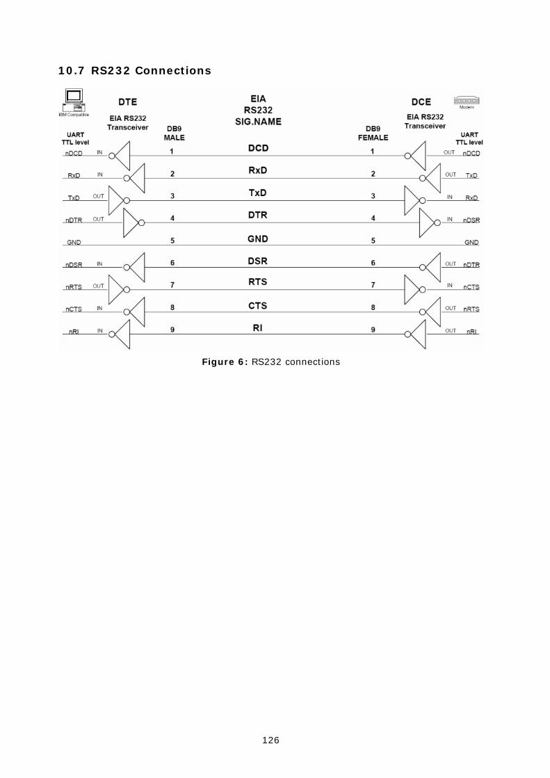
126
10.7 RS232 Connections
Figure 6: RS232 connections

127
10.8 PS Keys Used by iWRAP Firmware
TBA

128
10.9 Bluetooth Profiles Overview
10.9.1 Generic Access Profile (GAP)
GAP provides the basis for all other profiles and defines a consistent means to establish a baseband link between Bluetooth enabled devices. In addition to this, GAP defines the following:
• The features that must be implemented in all Bluetooth devices
• Generic procedures for discovering and linking to devices
• Basic user-interface terminology
10.9.2 RFCOMM
The RFCOMM protocol emulates the serial cable line settings and the status of an RS-232 serial port. It is used for providing serial data transfer. RFCOMM connects to the lower layers of the Bluetooth protocol stack through the L2CAP layer. By providing serial port emulation, RFCOMM supports legacy serial port applications while also supporting the OBEX protocol, among others. RFCOMM is a subset of the ETSI TS 07.10 standard, along with some Bluetooth-specific adaptations.
10.9.3 Service Discovery Protocol (SDP)
SDP defines how a Bluetooth client application acts to discover an available Bluetooth enabled server services and characteristics. SDP provides means for the discovery of new services becoming available when the client enters an area where a Bluetooth enabled server is operating. SDP also provides functionality for detecting when a service is no longer available. SDP defines a service as any feature that is usable by another Bluetooth device. A single Bluetooth enabled device can be both a server for and a client to services.
An SDP client communicates with an SDP server using a reserved channel on an L2CAP link to find out what services are available. When the client finds the desired service, it requests a separate connection to use the service. The reserved channel is dedicated to SDP communication so that a device always knows how to connect to the SDP service on any other device. An SDP server maintains its own SDP database, which is a set of service records that describe the services the server offers. Along with information describing how a client can connect to the service, the service record contains the service’s UUID, or a universally unique identifier.
10.9.4 Serial Port Profile (SPP)
SPP defines how to set-up virtual serial ports and to connect two Bluetooth enabled devices. SPP is based on the ETSI TS07.10 specification and uses the RFCOMM protocol to provide serial port emulation. SPP provides a wireless replacement for existing RS-232 based serial communications applications and control signals. SPP provides the basis for the DUN, FAX, HSP and LAN profiles. This profile supports a data rate of up to 128 kbit/sec. SPP is dependent on GAP.
10.9.5 Hands-Free Profile (HFP)
HFP describes how a gateway device can be used to place and receive calls for a hand-free device. A typical configuration is an automobile using a mobile phone for a gateway device. In the car, the stereo is used for the phone audio and a microphone is installed in the car for sending outgoing audio. HFP is also used for a personal computer to act as a speakerphone for a mobile phone in a home or office environment. HFP uses SCO to carry a mono PCM audio channel.
129
10.9.6 Dial-up Networking Profile (DUN)
DUN provides a standard to access the Internet and other dial-up services over Bluetooth technology. The most common scenario is accessing the Internet from a laptop by dialing up on a mobile phone wirelessly. It is based on SPP and provides for relatively easy conversion of existing products, through the many features that it has in common with the existing wired serial protocols for the same task. These include the AT command set specified in ETSI 07.07 and PPP.
Like other profiles built on top of SPP, the virtual serial link created by the lower layers of the Bluetooth protocol stack is transparent to applications using the DUN profile. Thus, the modem driver on the data-terminal device is unaware that it is communicating over Bluetooth technology. The application on the data-terminal device is similarly unaware that it is not connected to the gateway device by a cable.
DUN describes two roles, the gateway and terminal devices. The gateway device provides network access for the terminal device. A typical configuration consists of a mobile phone acting as the gateway device for a personal computer acting as the terminal role.
10.9.7 Object Push Profile (OPP)
OPP defines the roles of push server and push client. These roles are analogous to and must interoperate with the server and client device roles that GOEP defines. It is called push because the transfers are always instigated by the sender (client), not the receiver (server). OPP focuses on a narrow range of object formats to maximize interoperability. The most common acceptable format is the vCard. OPP may also be used for sending objects such as pictures or appointment details.
Source:
Bluetooth SIG, URL: http://www.bluetooth.com/Bluetooth/Learn/Works/Profiles_Overview.htm

130
10.10 Bluetooth Power Saving
SNIFF mode:
Once a Bluetooth device is connected to a Piconet, it can enter one of three power saving modes. In SNIFF mode, the activity of a Bluetooth device is lowered, enabling it to listen at a reduced rate to the Piconet. The interval or period between SNIFF is configurable.
The SNIFF mode is the least power efficient of all three power saving modes.
PARK state:
The Park state can be used when a Bluetooth device is connected to the Piconet but does not participate in traffic transfer.
The PARK state conserves most power compared with the other power saving modes.
General information about power saving:
On the SNIFF mode and on the PARK state, the devices have a reduced participation on the traffic of messages and packets. On the SNIFF mode, this occurs only at ‘SNIFF intervals’ and at the PARK state at the beacons (at this mode the device also listens to broadcast messages).
The main advantage for using PARK mode over SNIFF mode is that it leads to reduced power consumption and gives more time for the parked slave to participate on different Piconet(s).

131
10.11 HFP and HFP-AG commands
When using Hands Free, the following commands are supported:
Command Function AT mapping
ANSWER Answer to call ATA
DISCONNECT Hang-up call AT+CHUP
DTMF [code] Send DTMF code to Audio Gateway AT+VTS
HANGUP Hang-up call AT+CHUP
REJECT Reject call AT+CHUP
Table 8: HFP supported commands
When using Hands Free Audio Gateway following commands are supported:
Command Function AT mapping
ANSWER Answer to call callsetup 0, call 1
DISCONNECT Hang-up call callsetup 0, call 0
ERROR Send ERROR result to Hands Free error
HANGUP Hang-up call callsetup 0, call 0
REJECT Reject call callsetup 0, call 0
OK Send OK result to Hands Free ok
RING [count] [number]
Notify Hands Free for incoming call. [count] indicates the amount of indications. [number] displays the number from where the call is coming from
callsetup 1, ring, AT+CLIP ring is sent [count] times, if [number] is given, AT+CLIP is sent
STATUS Set status and send it to Hands Free
AT+CIND
Table 9: HFP-AG supported commands
The supported AT-commands for hands Free profile can be found from the specification document : https://www.bluetooth.org/foundry/adopters/document/HFP_1.5_SPEC_V10.

132
10.12 HFP and HFP-AG messaging
When HFP or HFP-AG profiles are used iWRAP will parse some of the AT commands coming from the remote end and will not “display” them to the user i.e. write to UART.
iWRAP will recognize and parse the following AT commands:
• AT+CLIP
• AT+COPS
• AT+VGS
• AT+CMIR
• AT+BLDN
• AT+CHUP
The messages HFP or HFP-AG profiles will produce are described below:
• “AT+VGS=%s\r”
Volume control info
• “%s %d READY\r\n”
SLC connected / HFP ready
• “%s %d NO CARRIER\r\n”
Call ended
• “%s %d CONNECT\r\n”
Call active
• “%s %d CALLING\r\n”
Outgoing call
• “%s %d RINGING\r\n”
Incoming call
• “%s %d BUSY\r\n”
Line busy
• “%s %d UNKNOWS (%x)”
Unrecognized command

133
%s = "HFP" or "HFP-AG" (expect with volume ctrl. where it's volume level)
%d = link ID
%x = HFP state
%y = unrecognized AT-command string

134
10.13 Bluetooth profile UUIDs
UUID: Bluetooth Profile:
0001 SDP
0003 RFCOMM
0008 OBEX
000C HTTP
000F BNEP
0100 L2CAP
1000 Service Discovery Server Service ClassID
1001 Browse Group Descriptor Service ClassID
1002 Public Browse Group
1101 Serial Port Profile
1102 LAN Access Using PPP
1103 Dial up Networking
1104 IrMC Sync
1105 OBEX Object Push Profile
1106 OBEX File Transfer Profile
1107 IrMC Sync Command
1108 Headset
1109 Cordless Telephony
110A Audio Source
110B Audio Sink
110C A/V_Remote Control Target
110D Advanced Audio Distribution Profile (A2DP)
110E A/V_Remote Control
110F Video Conferencing
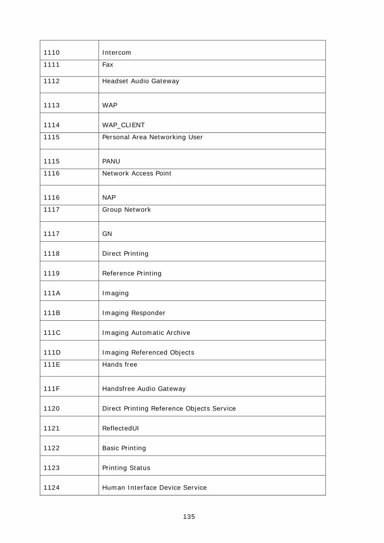
135
1110 Intercom
1111 Fax
1112 Headset Audio Gateway
1113 WAP
1114 WAP_CLIENT
1115 Personal Area Networking User
1115 PANU
1116 Network Access Point
1116 NAP
1117 Group Network
1117 GN
1118 Direct Printing
1119 Reference Printing
111A Imaging
111B Imaging Responder
111C Imaging Automatic Archive
111D Imaging Referenced Objects
111E Hands free
111F Handsfree Audio Gateway
1120 Direct Printing Reference Objects Service
1121 ReflectedUI
1122 Basic Printing
1123 Printing Status
1124 Human Interface Device Service

136
1125 Hardcopy Cable Replacement
1126 HCR_Print
1127 HCR_Scan
1128 Common_ISDN_Access
1129 Video Conferencing GW
112A UDI_MT
112B UDI_TA
112C Audio/Video
112D SIM_Access
112E Phonebook Access - PCE
112F Phonebook Access - PSE
1130 Phonebook Access
1200 PnP Information
1201 Generic Networking
1202 Generic File Transfer
1203 Generic Audio
1204 Generic Telephony
1205 UPNP_Service
1206 UPNP_IP_Service
1300 ESDP_UPNP_IP_PAN
1301 ESDP_UPNP_IP_LAP
1302 ESDP_UPNP_L2CAP
1303 Video Source
1304 Video Sink

137
1305 Video Distribution
Table 10: UUIDs and Profiles
For more information, please go to:
https://programs.bluetooth.org/apps/content/?doc_id=49709
138
11. TROUBLESHOOTING
11.1 I get no response from iWRAP?
Make sure your terminal settings are correct. Use PSTool to check the UART settings from the WRAP THOR Bluetooth module and make similar settings to your terminal software.
Check also your ECHO MODE settings. If you have set ECHO MODE to 0, you should not be able to see any responses.
You can also use iWRAP update to restore the firmware and default settings.
11.2 I changed ‘UART Baud rate’ key, but it didn’t seem to work?
UART baud rate is stored now into user keys instead of ‘UART baud rate’ key. Delete ‘User configuration data 26’ in order to return back to default settings 115200,8n1.
Notice also that if you change the baud rate with “SET CONTROL BAUD”, it does not affect the baud rate you need to use with PSTool, if you want to access parameters. This baud rate is defined by the ‘UART baud rate’ key.
AutoBCSP requires that iWRAP baud rate is same as ‘UART baud rate’ key.
11.3 Data coming from the UART is corrupted
If you are using ‘Deep sleep’ the minimum baud rate that can be used is 19200. Lower baud rates will corrupt the data.
11.4 I’m missing characters when I type ASCII commands.
If deep sleep is used, the first character written to UART wakes the module from the ‘Deep sleep’ and that’s why the character is lost. There are two ways to overcome this problem:
1. If you command iWRAP with a micro controller or processor, add ‘space’ or ‘line break’ characters in front of every command.
2. In PSTool, set parameter ‘EXIT deep sleep on CTS line activity’ to TRUE. Now ‘Deep sleep’ does not lose characters any more, but current consumption will increase.

139
12. KNOWN ISSUES
Issue Explanation
Using multiple DLCs can crash iWRAP Opening several connections to iWRAP using the same channel may crash the firmware. UUID should be used instead of a channel. This is a bug in the CSR firmware.
Listing remote SDP record may run out of memory
When a service discovery is made by using the SDP command and if root mode is used and remote device supports many services, iWRAP may run out of memory and reset. To overcome this, only a specific service should be searched for instead of using root mode.
Do not force sniff If sniff is enabled by using the ‘SET BT SNIFF’ command, iWRAP cannot unsniff if remote end requests for it.
Frame mode flow control hangs In multiplexing mode, the firmware will hang if data length is longer than 100 bytes. A physical reset is needed. This is a bug in the CSR firmware.
Data does not leave buffer Sometimes if small amount of data is received, it may remain in the incoming buffer until more data is received. This is a bug in the CSR firmware.
Inquiry RSSI and clock caching If RSSI in the inquiry and clock offset caching are enabled, connections can not be opened. This is a bug in the CSR firmware.
HW flow control If HW flow control is not used and iWRAP buffers are filled either in data or command mode, the firmware will hang and needs a physical reset. This is a bug in the CSR firmware.
Simultaneous connection between two iWRAPs
Two simultaneous ACL connections can not be opened between two iWRAPs.
SET CONTROL INIT RESET Issuing SET CONTROL INIT RESET will result in an infinite reset loop. PSKEY_USR_27 must be deleted to survive this condition.
Command parser iWRAP command parser is case sensitive with UUIDs and Bluetooth addresses
Table 11: iWRAP known issues

140
13. SUPPORT
• For technical questions and problems, please contact: [email protected]
• Firmware, parameters, tools and documentation can be downloaded from:
http://www.bluegiga.com/techforum/

141
14. RELATED DOCUMENTATION
Please also take a look at the following documentation:
• iWRAP Update Client User Guide
• DFU Wizard User Guide
• BlueFlash User Guide
• PSTool User Guide
• Performance Measurement Guide
• Bluetooth specification (www.bluetooth.org)
Visit also Tech-forum (www.bluegiga.com/techforum/) for additional information and design references.

142
15. IWRAP CONFIGURATION EXAMPLES
Some iWRAP configuration and usage examples are presented in the following chapters.
15.1 Simple SPP Slave
In this example, iWRAP is configured to be a transparent SPP slave module, which only accepts connections and transmits data. No events or any other information is displayed. The configuration is displayed in the figure below:
Figure 7: Slave configuration
The important settings in the figure are the following:
• SET BT PAGEMODE 3 2000 1
With this setting, iWRAP is configured to be visible in the inquiry and to be connectable as a slave module should be.
On the other hand, in some cases the slave mode does not need to be visible in the inquiry. In this case, our setting would be: SET BT PAGEMODE 2 2000 1. If iWRAP is not visible in the inquiry, the current consumption will be 1-2mA lower.
• SET BT ROLE 0 f 7d00
With this setting, we have simply defined that iWRAP does not ask for a master-slave switch when it us being connected. On the other hand, all the link options (power saving etc.) are enabled if master wants to use them. This is the default setting.
• SET CONTROL ECHO 0
This is an important setting since we want the slave module to be transparent. That is why we disable all the event messages and boot banner by setting echo mode to 0.
143
Other options:
• The timeouts for the slave module can be also configured. For the slave, probably the supervision timeout is important, that is, when the slave notices that the connection is lost. This timeout is configured by using the “SET BT ROLE” command.
• Sometimes the data rate is important and the slave does not need to know about data and command mode switches. In these cases, it might be useful to disable the escape sequence to obtain a higher data rate. This is done, for example, by issuing command: “SET CONTROL ESCAPE – 00 1”. With the second parameter, one of the available PIO pins can be dedicated to be used as a DTR signal (to close the connection).
• To enable automatic power saving during connections, “SET BT SNIFF” with appropriate parameters can be used.
• To minimize idle time power consumption, deep sleep can be enabled by issuing the “SET CONTROL CONFIG 10” command.

144
15.2 Simple SPP Master
In this example, iWRAP is configured to be a transparent SPP master module, which always tries to keep/open a connection to a defined device and keep up transparent data mode where events or any other information are not displayed. The configuration is displayed in the figure below:
Figure 8: Transparent master
The important settings in the master module are the following:
• SET BT PAGEMODE 0 2000 1
The master module does not need to be visible in the inquiry nor connectable, since it only opens connection(s). That is why we have chosen this page mode. This also conserves power and speeds up connection openings.
145
• SET BT PAIR 00:07:80:04:00:ae 4dcab77aaa01758661c669a341a3faf4
The master module needs to know where it opens the connection. In iWRAP, this is done based on the pairings. The slave module is the one and only paired device in the master’s memory. See “SET CONTROL AUTOCALL” for more information.
• SET BT ROLE 0 f 7d00
This is the default setting. Usually the master module is a Piconet master, but in some cases slaves want to do a master slave switch. That is why we allow it to be more flexible with any kind of devices.
Tip:
When configuring Bluetooth networks with the WRAP Access Server, it is wise to configure the access server to act as a master device, even if it does not open the actual connections. For these kind of cases, it is also wise to allow the master slave switch even on a master module.
• SET CONTROL AUTOCALL 1
This is the key setting in a master module, since it enables the autocall feature. Parameter ‘1’ indicates that the master module tries to open the connection using RFCOMM channel 1. This is only a safe setting when the slave device is another iWRAP module, since iWRAP uses Serial Port Profile always on channel 1. With other devices, instead of ‘1’ you should use ‘1101’ (UUID) if you want to open an SPP connection.
Tip:
Using the channel instead of UUID is faster, because when using UUID a service discovery is made and that takes around 300ms time. However, UUID is safer since the channel for SPP might vary between different devices.
• SET CONTROL ECHO 0
This is an important setting since we want the master module to be transparent. That is why we disable all the event messages and boot banner by setting echo mode to 0.
• SET CONTROL CD 80 0
When using a transparent master module, it is difficult to know if there is a connection or not, since no events are displayed. That is why we have enabled the carrier detect signal with command SET CONTROL CD 80 0. This means that when there is a connection, IO7 is driven high. This can also be done in the slave module.
Tip:
Using IO7 for CD signal is wise especially when using WRAP THOR Evaluation Kits, since there is a led connected to IO7.

146
Options:
• The timeouts for the master module can be also configured. For the master, probably the supervision timeout is important, that is, when it notices that the connection is lost. This timeout is configured by using the “SET BT ROLE” command. Also the time how long a connection establishment can take before error occurs might be important, at least for non transparent masters. This, on the other hand, can be configured by using the “SET BT PAGEMODE” command.
• Sometimes the data rate is important and there is a possibility to use DTR signaling for controlling data and command mode switches. In these cases, it might be useful to disable the escape sequence to obtain a higher data rate. This is done, for example, by issuing command: “SET CONTROL ESCAPE – 80 1”. Parameter ‘80’ defines that IO 7 is used as a DTR signal. Notice, however, that CD and DTR signals cannot be configured to use the same IO.
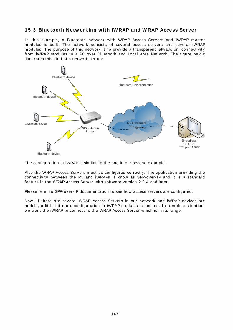
147
15.3 Bluetooth Networking with iWRAP and WRAP Access Server
In this example, a Bluetooth network with WRAP Access Servers and iWRAP master modules is built. The network consists of several access servers and several iWRAP modules. The purpose of this network is to provide a transparent ‘always on’ connectivity from iWRAP modules to a PC over Bluetooth and Local Area Network. The figure below illustrates this kind of a network set up:
The configuration in iWRAP is similar to the one in our second example.
Also the WRAP Access Servers must be configured correctly. The application providing the connectivity between the PC and iWRAPs is know as SPP-over-IP and it is a standard feature in the WRAP Access Server with software version 2.0.4 and later.
Please refer to SPP-over-IP documentation to see how access servers are configured.
Now, if there are several WRAP Access Servers in our network and iWRAP devices are mobile, a little bit more configuration in iWRAP modules is needed. In a mobile situation, we want the iWRAP to connect to the WRAP Access Server which is in its range.
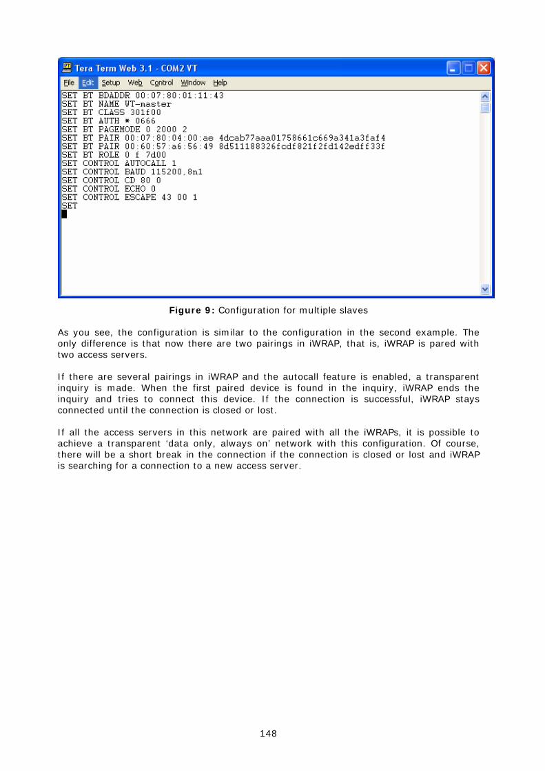
148
Figure 9: Configuration for multiple slaves
As you see, the configuration is similar to the configuration in the second example. The only difference is that now there are two pairings in iWRAP, that is, iWRAP is pared with two access servers.
If there are several pairings in iWRAP and the autocall feature is enabled, a transparent inquiry is made. When the first paired device is found in the inquiry, iWRAP ends the inquiry and tries to connect this device. If the connection is successful, iWRAP stays connected until the connection is closed or lost.
If all the access servers in this network are paired with all the iWRAPs, it is possible to achieve a transparent ‘data only, always on’ network with this configuration. Of course, there will be a short break in the connection if the connection is closed or lost and iWRAP is searching for a connection to a new access server.

149
15.4 Dial-up Networking
iWRAP has some support for Dial-Up Networking (DUN). The most common use case of DUN is a connection to a mobile phone. Modern smart phones support the DUN profile and it gives you access to the GSM/GRPS modem inside the phone, that is, you can control the phone with AT commands over a Bluetooth link (send SMS messages, open GSM or GPRS connections, and browse the phone book). The simplified example below shows how to open a DUN connection to a phone and how to send an “AT” command to the phone.
Host iWRAP Phone
"SET BT AUTH * 1234"
"CALL 00:00:00:00:00:00 1103 RFCOMM"
"CALL 0"
Open DUN connection
If not pairied,ask for pin
If PIN ok, and iWRAPnot a trusted device
ask to acceptconnection
Connection accepted
"CONNECT 0 RFCOMM 3"
"AT"
"OK"
Figure 10: How to open a DUN connection to a mobile phone
The pin needs to be set, since for some reason most of the mobile phones always require the PIN code authentication.
It may be wise to do the pairing from the mobile phone and make the iWRAP module ‘trusted’. Once this is done, the phone does not ask for the PIN code every time the connection is opened.
Notice that not all the mobile phones support the same AT commands!

150
15.5 OBEX Object Push Profile Server
This example shows how to set up a simple Object Push Profile (OPP) server for receiving files over Bluetooth.
Host iWRAP Phone
"SET PROFILE OPP on"
RESET
Send file viaBTOpen OPP connection
"RING [bd_addr] [channel] OBEX
"SET BT AUTH *"
"PUT [size] [mime] [filename]
file
Close OPP connection
"NO CARRIER [link_id] ERROR 0"
Figure 11: Receiving files through OPP
“SET PROFILE OPP on” enables the needed OBEX profiles in iWRAP for receiving the files. In the example, the PIN code is disabled so that the phone does not prompt for the PIN when sending the file.
OPP can be disabled by using the “SET PROFILE OPP” command and issuing “RESET”.
Some devices also require that that Class of Device (CoD) is configured correctly before they are able to send files via OBEX. A correct class of device setting can be found from the Bluetooth specification.
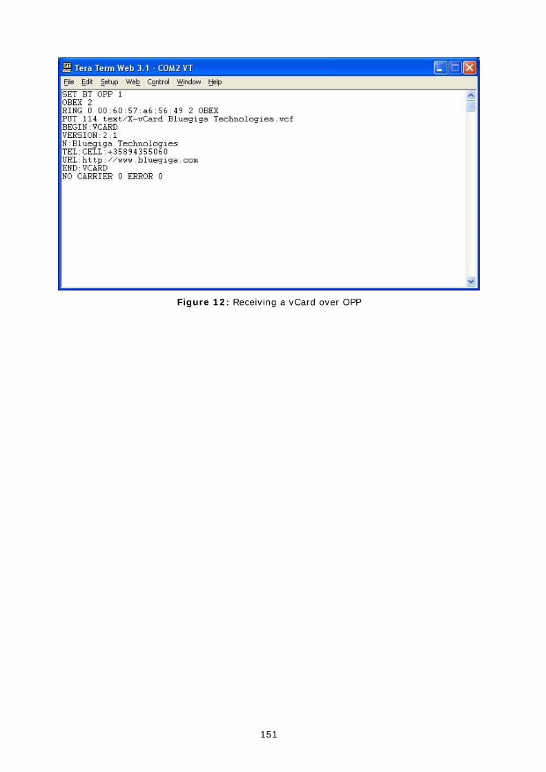
151
Figure 12: Receiving a vCard over OPP

152
15.6 iWRAP to iWRAP Audio + Data Connection
iWRAP also supports SCO (audio) connections. This example shows how to open a simple iWRAP audio connection.
Host iWRAP iWRAP
"SET CONTROL CONFIG 100"
"CALL 00:07:80:00:00:00 1101 RFCOMM
Open RFCOMM connection
"+++" or DTR signal
"SCO ENABLE"
"CONNECT [link_id] RFCOMM [channel]
Accept RFCOMM connection
READY.
"SCO OPEN [link_id]"
Host
"SET CONTROL CONFIG 100"
"SCO ENABLE"
"RING [link id] 00:07:80:00:00:00 [channel] RFCOMM
"CALL 0"
"CONNECT [link_id] SCO"
Open SCO connection
Accept SCO connection
"SELECT [link id]" (RFCOMM link)
ACL data connection via UART / SCO Audio connection via PCM
Figure 13: ACL data + SCO audio connection setup
“SET CONTROL CONFIG 100” is a fix to a CSR bug, which disables the master-slave switch and is needed for SCO connections. This command only needs to be given once. The “SCO ENABLE” command is needed, on the other hand, to indicate to iWRAP that audio connections will be used. This command needs to be given every time after a reset. “SET CONTROL INIT SCO ENABLE” can be used to automatically enable the feature.
PS key “Map SCO over PCM” must be set to TRUE for the audio to be transmitted.
Audio is routed directly to the PCM interface of the module. The existing ACL connection can be used to send and receive data.

153
15.7 iWRAP to Hands-Free Audio Connection
iWRAP can also be used to transmit audio to a Bluetooth headset in a similar way as iWRAP to iWRAP audio works. The example below shows how this is done.
Host iWRAP Headset
"SET CONTROL CONFIG 100"
"CALL 00:07:80:00:00:00 111e HFP-AG
Open RFCOMM connection
HFP status messages
"SET PROFILE HFP-AG ON"
"CONNECT [link_id] HFP-AG [channel]
Accept RFCOMM connection
"ring"
"CALL 0"
HFP-AG [link_id] RINGING
Open SCO connection
Accept SCO connection
SCO connection for audio
"SET BT AUTH* [pin_of_headset]"
"RESET"
One timeconfiguration
Press answer
HFP-AG [link_id] CONNECT
RFCOMM connection for AT-commands
Reset
Figure 14: iWRAP to headset audio connection
Audio connection to a headset is pretty straightforward to setup. First, the initializations must be done, second the HFP-AG connection to headset-profile is opened (UUID for hands-free is 111e) and finally, the SCO connection must be set up.
Once all this is done, the RFCOMM connection can be used to transmit AT commands between the headset and iWRAP and the SCO connection to transmit audio. Please refer to the headset / hands-free profile specification for supported AT commands:
https://www.bluetooth.org/foundry/adopters/document/HFP_1.5_SPEC_V10
NOTE: UUIDs for HFP and HFP-AG need to be given in lower case format i.e. 111e and 111f, NOT 111E and 111F.
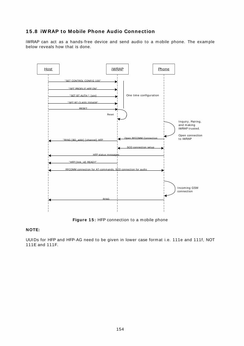
154
15.8 iWRAP to Mobile Phone Audio Connection
iWRAP can act as a hands-free device and send audio to a mobile phone. The example below reveals how that is done.
Host iWRAP Phone
"SET CONTROL CONFIG 100"
"RING [BD_addr] [channel] HFP
"SET PROFILE HFP ON"
Open RFCOMM Connection
HFP status messages
RFCOMM connection for AT-commands, SCO connection for audio
"SET BT AUTH * [pin]
Inquiry, Pairing,and makingiWRAP trusted.
Open connectionto iWRAP
"HFP [link_id] READY"
RESET
Reset
One time configuration
"SET BT CLASS 200408"
SCO connection setup
Incoming GSMconnection
RING
Figure 15: HFP connection to a mobile phone
NOTE: UUIDs for HFP and HFP-AG need to be given in lower case format i.e. 111e and 111f, NOT 111E and 111F.

155
15.9 Wireless IO Replacement
iWRAPs can be used to do wireless IO replacement, that is, to transmit the status of GPIO PINs over the SPP link. This means that if the status of the local IO changes, so does the status of the remote IO. This functionality can be accomplished by using the MSC (Modem Status Control) feature in iWRAP.
Host iWRAP iWRAP
"SET CONTROL MSC DTE 80 20 0 0 0 0"
"CALL 00:07:80:00:00:00 1101 RFCOMM
Open RFCOMM connection
Change PIO5 status
"CONNECT [link_id] RFCOMM [channel]
Accept RFCOMM connection
Host
"SET CONTROL MSC DCE 20 80 0 0 0 0"
"RING [link id] 00:07:80:00:00:00 [channel] RFCOMM
"CALL 0"
PIO7 status changes
Change PIO5 status
MSC status information
PIO7 status changes MSC status information
Figure 16: Wireless IO replacement connection
The example above was done with WT12 evaluation kits. In the evaluation kit, there is a DSR button in PIO5 and a LED in PIO7. Parameter 80 matches with PIO7 and parameter 20 with PIO5. So whenever DSR button is pressed in the local device, the LED status changes in the remote end.
NOTE:
Switching the IO status very rapidly may reset iWRAP. There is also a delay when transmitting the MSC status over the Bluetooth link. Without power saving in use, this delay is roughly 20ms and if power saving is in use, the delay depends on SNIFF mode parameters.