j 280 owner s guide - linux kernel the dds tape drive operation 3-10 using device files 3-12...
TRANSCRIPT

J 280Owner’s Guide
�
Workstation Systems Group
HP Part No. A2876–90013Edition E1196
Printed in U.S.A.

Hewlett-Packard Co. 1996
First Printing: November 1995
UNIX is a registered trademark in the United States and other countries, licensed exclusively throughX/Open Company Limited.
NOTICE
The information contained in this document is subject to change without notice.
HEWLETT-PACKARD MAKES NO WARRANTY OF ANY KIND WITH REGARD TO THISMATERIAL INCLUDING BUT NOT LIMITED TO THE IMPLIED WARRANTIES OFMERCHANTABILITY AND FITNESS FOR A PARTICULAR PURPOSE. Hewlett-Packard shallnot be liable for errors contained herein or for incidental or consequential damages in connection withthe furnishing, performance or use of this material.
Hewlett-Packard assumes no responsibility for the use or reliability of its software on equipment that isnot furnished by Hewlett-Packard.
This document contains proprietary information that is protected by copyright. All rights reserved. Nopart of this document may be photocopied, reproduced or translated to another language without theprior written consent of Hewlett-Packard Company.
RESTRICTED RIGHTS LEGEND. Use, duplication, or disclosure by government is subject torestrictions as set forth in subdivision (c) (1) (ii) of the Rights in Technical Data and Computer SoftwareClause at DFARS 252.227.7013. Hewlett-Packard Co., 3000 Hanover St., Palo Alto, CA 94304.
10 9 8 7 6 5 4 3 2 1

xii

Table of Contents
System Overview 1-1................................................................................Product Description 1-3...........................................................................................System Unit Front Panel Controls, LED, and LCD 1-6............................................
System LCD 1-7........................................................................................................................System Power Switch 1-7..........................................................................................................System Power LED 1-8.............................................................................................................Removable Device Buttons and LEDs 1-8................................................................................
System Unit Rear Panel Connectors 1-10.................................................................Audio Connectors 1-12................................................................................................................Keyboard Connectors 1-14..........................................................................................................HP Parallel I/O Connector 1-15...................................................................................................Network Connectors 1-15............................................................................................................RS-232C Serial Input/Output Connector 1-15.............................................................................SCSI Connectors 1-16.................................................................................................................Power Cord Connector 1-16........................................................................................................
Monitors 1-17.............................................................................................................Pointing Devices 1-18................................................................................................Operating System Overview 1-19..............................................................................Important Information You Need to Note 1-20...........................................................
LANIC ID 1-20.............................................................................................................................IP Address and Subnetwork Mask Information 1-21...................................................................
Networking Overview 1-22........................................................................................Mail 1-22......................................................................................................................................telnet 1-22....................................................................................................................................rlogin 1-22....................................................................................................................................ftp 1-23.........................................................................................................................................rcp 1-23........................................................................................................................................NFS 1-23.....................................................................................................................................
Using Your CD-ROM Drive 2-1.................................................................CD-ROM Drive and CD- ROM Media Descrip-tions 2-3..........................................
CD-ROM Drive 2-3....................................................................................................................CD-ROM Media 2-5...................................................................................................................
Operating the CD- ROM Drive 2-6..........................................................................Loading and Unloading a CD-ROM Disc 2-6.............................................................................Verifying the CD-ROM Drive Operation 2-11...............................................................................Using Device Files 2-14...............................................................................................................
Mounting and Unmounting a CD- ROM Disc 2-15....................................................Mounting a CD-ROM Disc Using SAM 2-15................................................................................Unmounting a CD-ROM Disc Using SAM 2-17...........................................................................Reading the Busy Light 2-19.......................................................................................................Troubleshooting 2-20...................................................................................................................
Using Your DDS Tape Drive 3-1..............................................................DDS Tape Drive and Data Cassette Descriptions 3-3.............................................
DDS Drive 3-3............................................................................................................................Data Cassettes 3-7....................................................................................................................Setting the Write-Protect Tab on a Data Cassette 3-8..............................................................
Operating the DDS Tape Drive 3-9.........................................................................Loading and Unloading a Data Cassette 3-9.............................................................................
Verifying the DDS Tape Drive Operation 3-10.............................................................................Using Device Files 3-12...............................................................................................................Determining Available Device Files 3-12.....................................................................................Archiving Data in Compressed and Noncompressed Mode 3-14................................................Writing to a Data Cassette 3-15...................................................................................................Restoring Files from a Data Cassette to Your System 3-15........................................................Listing the Files on a Data Cassette 3-17....................................................................................Further Command Information 3-18............................................................................................Media Interchangeability Restrictions 3-18..................................................................................Troubleshooting 3-18...................................................................................................................Ordering Information 3-19............................................................................................................
Using Your 3.5-Inch Floppy Disk Drive 4-1............................................Using the Floppy Diskette 4-3.................................................................................
Setting the Write-Protect Tab on a Diskette 4-3........................................................................Inserting and Removing a Diskette 4-4......................................................................................
Operating the Floppy Drive 4-5...............................................................................Verifying the Floppy Drive Configuration 4-5.............................................................................Using Device Files 4-6...............................................................................................................Formatting a New Diskette 4-8..................................................................................................Transferring Data To and From a Floppy Diskette 4-8..............................................................Saving Files to a Floppy Diskette 4-9........................................................................................Restoring Files from a Floppy Diskette to Your System 4-9......................................................Listing the Files on a Floppy Diskette 4-10..................................................................................For More Information 4-10...........................................................................................................Configuring the Floppy Driver 4-12..............................................................................................Troubleshooting 4-12...................................................................................................................Ordering Information 4-12............................................................................................................
Solving Problems 5-1...............................................................................Common Problems and Solutions 5-3.....................................................................Dealing with a Boot Failure 5-10...............................................................................Memory Failures 5-11................................................................................................LCD-Indicated Problems 5-12...................................................................................Running System Verification Tests 5-15...................................................................
Safety and Regulatory Statements A-1...................................................Emissions A-3..........................................................................................................
Federal Communications Commission (FCC) A-3.....................................................................Regulations A-3.......................................................................................................
VCCI Class 1 ITE A-4................................................................................................................Emissions Regulations Compliance A-4..................................................................Datacom Users Statement A-4................................................................................
(United A-4.................................................................................................................................Kingdom Only) A-4.....................................................................................................................
Acoustics A-4...........................................................................................................Regulation On Noise Declaration For Machines �3. GSGV A-4.................................................
Electrostatic Discharge (ESD) Precautions A-4.......................................................Laser Safety Statement (For U. S. A. Only) A-5......................................................IEC 825 Class 1 Laser Label A-5.............................................................................Warnings and Cautions A-6.....................................................................................

Changing Your Workstation s Hardware Configuration B-1.................Checking the SCSI IDs B-3......................................................................................Opening the System Unit B-6..................................................................................Closing the System Unit B-8....................................................................................Installing Removable Media Devices B-10................................................................
CD-ROM Drive B-15....................................................................................................................DDS Tape Drive B-17..................................................................................................................Floppy Drive B-21........................................................................................................................
Adding a Hard Drive B-28..........................................................................................Installing a Hard Disk Drive B-31.................................................................................................Configuring a Hard Drive B-34.....................................................................................................
Installing Additional Memory B-37.............................................................................Replacing the B-45....................................................................................................Processor B-45..........................................................................................................Module 1. B-45...........................................................................................................Installing an EISA or Graphics Board B-51................................................................Changing Your Monitor Type B-61............................................................................
Setting the Monitor Type from the Boot Console Interface B-61..................................................Setting the Monitor Type at Power On B-61................................................................................
SCSI Connections C-1..............................................................................SCSI Bus Differences C-3........................................................................................SCSI Restrictions C-5..............................................................................................
Cables C-5.................................................................................................................................Connectors and Terminator C-7.................................................................................................SCSI Configuration Constraints C-7...........................................................................................
Determining SCSI Bus Length C-9..........................................................................Single-Ended SCSI-2 Bus Length C-9.......................................................................................Fast, Wide SCSI-3 Bus Length C-12............................................................................................
Assigning SCSI Device IDs C-14...............................................................................Single-Ended Standard System SCSI Device IDs C-16...............................................................Fast, Wide SCSI IDs C-20............................................................................................................
Connecting to the SCSI Ports C-21...........................................................................System SCSI Port Connection C-21............................................................................................
The Boot Console Interface D-1...............................................................Boot Console Interface Features D-2.......................................................................Accessing the Boot Console Interface D-7..............................................................Booting Your Workstation D-9..................................................................................Searching for Bootable Media D-12...........................................................................Resetting Your Workstation D-13...............................................................................Displaying and Setting Paths D-14............................................................................Displaying and Setting the Monitor Type D-16...........................................................
The Monitor Command D-16........................................................................................................Displaying the Current Monitor Configuration D-18...................................................
Setting the Monitor Type D-19.....................................................................................................Setting the Monitor Type at Power On D-22..............................................................

Displaying the Current Memory Configuration D-24..................................................Displaying the Status of the System I/O D-29............................................................Setting the Auto Boot and Auto Search Flags D-31...................................................Displaying and Setting the Security Mode D-33.........................................................Displaying and Setting the Fastboot Mode D-34........................................................Displaying the LAN Station Address D-35.................................................................Displaying System Information D-35..........................................................................Displaying PIM Information D-36...............................................................................

xiii
Preface

xiv
This owner’s guide describes how to use your HP 9000 J280 worksta-tion.
This manual assumes that you have installed your workstation as described in the J Class Hardware Installation Guide.

xv
This guide is intended for HP 9000 J280 workstation users.
See Appendix A in the back of this manual for safety and regulatorystatements that apply to this workstation.
Please refer to the Release Document(s) you received with your sys-tem or system software for additional information that we may nothave been able to include in this guide at the time of its publication.
Audience
Safety andRegulatoryStatements
ReleaseDocument(s)
xvi
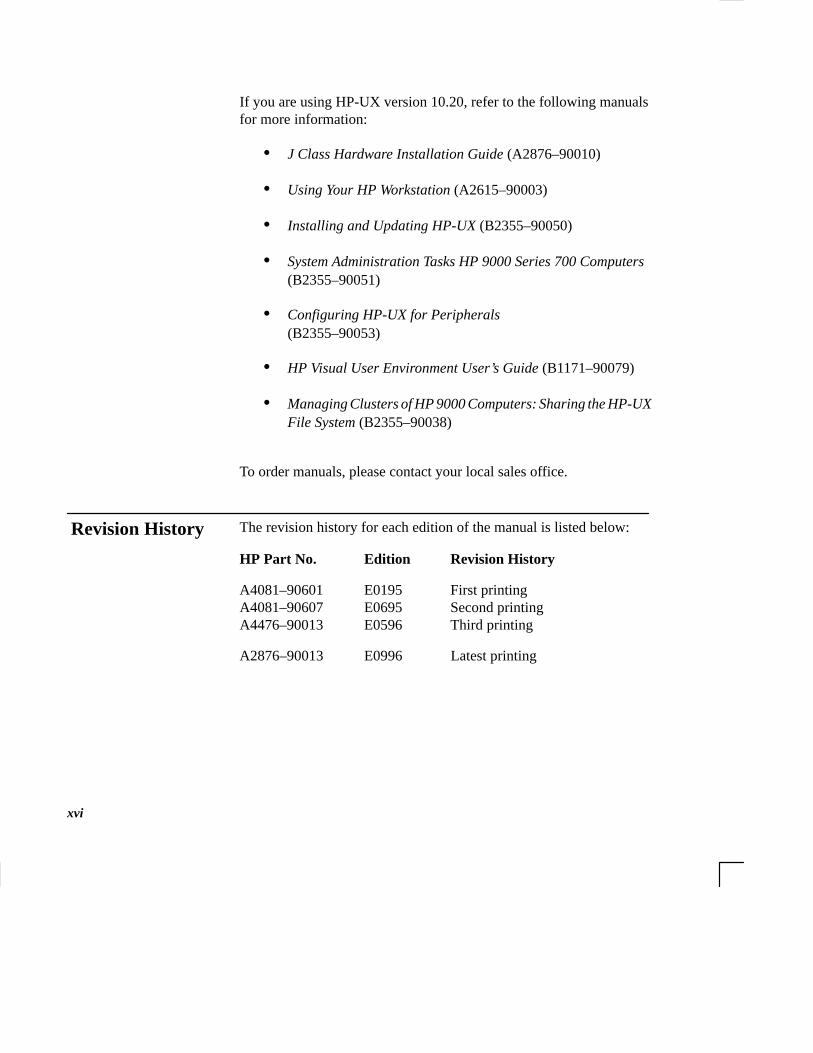
If you are using HP-UX version 10.20, refer to the following manualsfor more information:
• J Class Hardware Installation Guide (A2876–90010)
• Using Your HP Workstation (A2615–90003)
• Installing and Updating HP-UX (B2355–90050)
• System Administration Tasks HP 9000 Series 700 Computers(B2355–90051)
• Configuring HP-UX for Peripherals(B2355–90053)
• HP Visual User Environment User’s Guide (B1171–90079)
• Managing Clusters of HP 9000 Computers: Sharing the HP-UXFile System (B2355–90038)
To order manuals, please contact your local sales office.
The revision history for each edition of the manual is listed below:
HP Part No. Edition Revision History
A4081–90601 E0195 First printingA4081–90607 E0695 Second printingA4476–90013 E0596 Third printing
A2876–90013 E0996 Latest printing
Revision History

xvii
Unless otherwise noted in the text, this guide uses the following sym-bolic conventions.
literal values Bold words or characters in formats and command de-scriptions represent commands or key words that youmust use literally. Pathnames are also in bold.
user-supplied Italic words or characters in formats and commandvalues descriptions represent values that you must supply.
sample user In examples, information that the user enters appears input in color.
output Information that the system displays appears in this typeface .
Enter A colored rectangle with rounded corners and a key label denotes a key on your keyboard. (In this manualwe refer to the Enter key. On your keyboard the keymay be labeled either Enter or Return.)
Screen Button This colored symbol with a label in it denotes an HPVUE screen button. A screen button is a key or buttonwhich is drawn on your workstation’s graphic displayby HP VUE. It works like a keyboard key, except thatyou must move the mouse cursor over it and press theleft mouse button to activate it. The screen button’s la-bel describes its function.
This symbol indicates a notice.
This symbol indicates a procedure.
This symbol indicates a caution.
This symbol indicates the end of a chapter or a part ofthis guide.
DocumentationConventions

xviii
If you have any questions, suggestions, or problems with our hard-ware, software, or documentation, please call 1–888–301–5932 (US& Canada) or contact the HP Response Center for your country.
Questions,Suggestions, orProblems

1-1
Chapter 1
System Overview
• Product description
• System unit front panel controls, LED, and LCD
• System unit rear panel connectors
• Monitors
• Keyboard and Mouse
• Pointing devices
• Operating system overview
• Important information you need to note
• Networking overview

1-2
This chapter introduces the HP 9000 J 280 workstation. Its purpose isto familiarize you with your workstation and its controls and indica-tors.
The instructions in this chapter assume you are using the HP-UX version 10.20 or later operating system with the HP VUE version 3.0 interface.
1-3
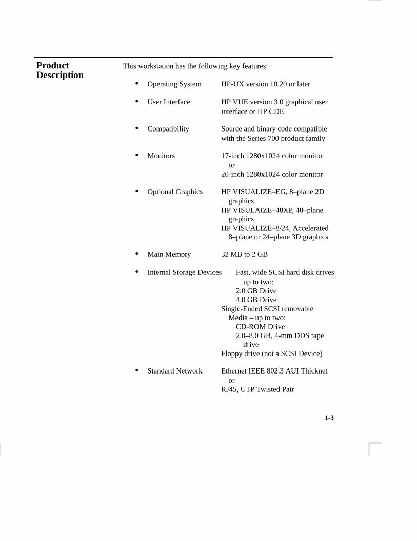
This workstation has the following key features:
• Operating System HP-UX version 10.20 or later
• User Interface HP VUE version 3.0 graphical user interface or HP CDE
• Compatibility Source and binary code compatiblewith the Series 700 product family
• Monitors 17-inch 1280x1024 color monitoror
20-inch 1280x1024 color monitor
• Optional Graphics HP VISUALIZE–EG, 8–plane 2D graphics
HP VISULAIZE–48XP, 48–plane graphics
HP VISUALIZE–8/24, Accelerated 8–plane or 24–plane 3D graphics
• Main Memory 32 MB to 2 GB
• Internal Storage Devices Fast, wide SCSI hard disk drivesup to two:
2.0 GB Drive4.0 GB Drive
Single-Ended SCSI removable Media – up to two:
CD-ROM Drive2.0–8.0 GB, 4-mm DDS tape
driveFloppy drive (not a SCSI Device)
• Standard Network Ethernet IEEE 802.3 AUI Thicknet or
RJ45, UTP Twisted Pair
Product Description
1-4
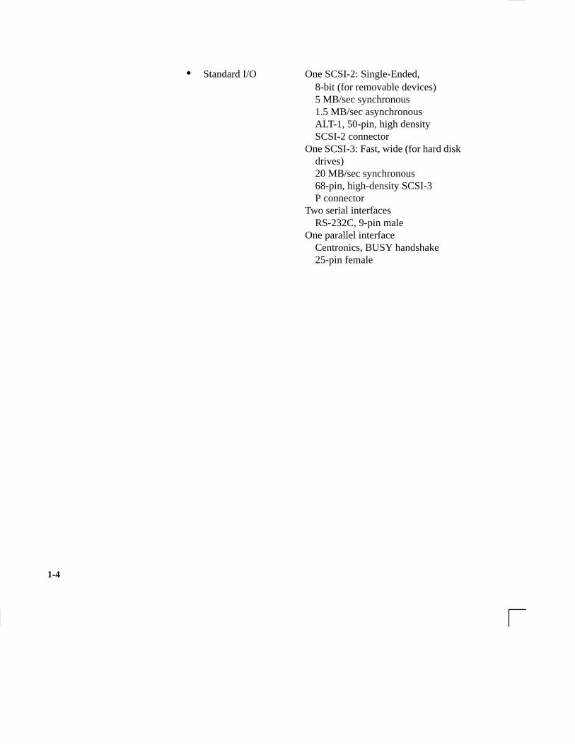
• Standard I/O One SCSI-2: Single-Ended, 8-bit (for removable devices)5 MB/sec synchronous1.5 MB/sec asynchronousALT-1, 50-pin, high densitySCSI-2 connector
One SCSI-3: Fast, wide (for hard diskdrives)20 MB/sec synchronous68-pin, high-density SCSI-3 P connector
Two serial interfacesRS-232C, 9-pin male
One parallel interfaceCentronics, BUSY handshake25-pin female

1-5
• EISA/GSC Five slots total; four EISA and three GSC that can be used as follows: two individual EISA, one individual GSC, and two combination EISA or GSC.
• Keyboard PS/2 Keyboard
• Mouse PS/2 Mouse

1-6
Before powering on your system, you should become familiar withthe system unit controls.
Figure 1–1 shows the the system unit front panel controls.
������ ���
������ � ��� �����
������ � ��� ���
Figure 1–1. System Unit Front Panel Controls
System UnitFront PanelControls, LED,and LCD

1-7
System LCD
The Liquid Crystal Display (LCD) is located on the left side of thefront panel. It displays messages about the state of the system, includ-ing error codes. The following symbols appear in the LCD, represent-ing the different system activities shown:
Operating system running
Disk Access in progress
Network Receive in progress
Network Transmit in progress
Figure 1–2. LCD Symbols
System Power Switch
Use the Power switch to power the system unit on and off.
CAUTION: Do not turn off the power to your workstationwithout first performing the recommendedshutdown procedure. If you do not shut downyour workstation properly, you can damage theprograms and data on your disk.
Using the proper shutdown method for yourworkstation and operating system also ensuresthat your system produces the proper diagnosticand self test messages, and broadcasts a warn-ing message to remote terminals that it is aboutto shutdown.

1-8
Follow the instructions in Using Your HP Workstation to shut downyour workstation.
System Power LED
The Power Light Emitting Diode (LED) is located on the left side ofthe front panel. It lights when the system unit power is on and flashesuntil the OS is booted. Once the OS is booted, the LED remains onwithout flashing.
Removable Device Buttons and LEDs
Depending on your configuration, you can have up to two (2) of thefollowing removable device drives:
• CD-ROM disc drive
• DDS tape drive
• Floppy diskette drive
NOTICE: You cannot have two of the same type of de-vice. For example, you can have a CD-ROMdevice and a floppy device, but not two CD-ROMs.
A description of each drive’s controls and indicators is in the chapterdescribing that device, later in this book.
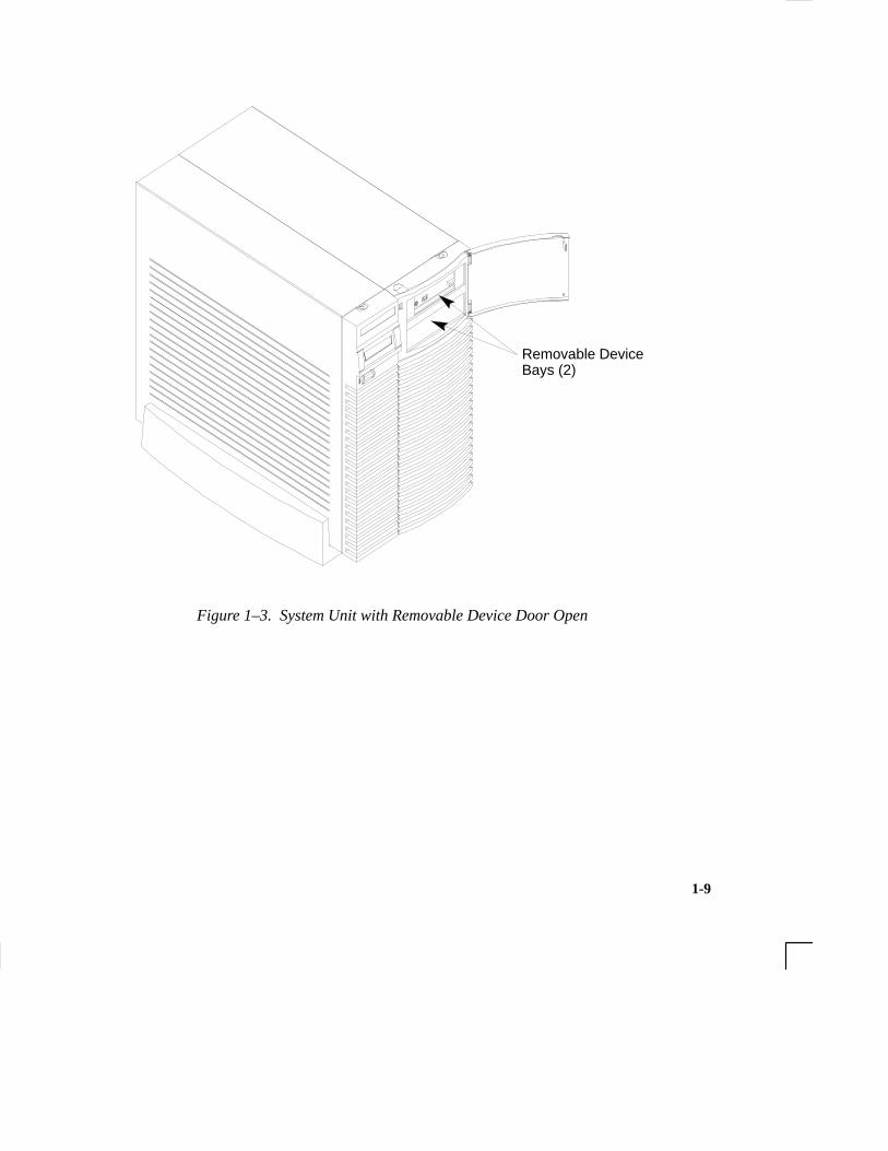
Figure 1–3 shows the system unit with the removable device dooropen. A removable device is in the top bay; a blank covers the emptybottom bay.
1-9
Removable DeviceBays (2)
Figure 1–3. System Unit with Removable Device Door Open
1-10
This section describes the following connectors on the system unit’srear panel:
• Audio connectors (including headphones and microphone)
• PS/2 keyboard and mouse connectors
• HP parallel Centronics I/O connector
• 802.3 AUI LAN connector
• 802.3 TP (Twisted Pair) LAN connector
• RS-232C serial I/O connectors
• SCSI connectors (including fast, wide SCSI-3 and single-ended SCSI-2
• TOC button
• Power cord connector
NOTICE: To maintain FCC/EMI compliance, verify thatall cables are fully seated and properly fastened.
Figure 1–4 shows the locations of the connectors on the system unit’srear panel.
System UnitRear Panel Connectors

1-11
����0//+*
�*+/� .&+1*�
��./�� �'"#� ����3��+**#!/+-�
�'*%(#"3�*"#"����3� �+**#!/+-�
�#2 +�-"��+**#!/+-
��� � ���+**#!/+-
�1'./#"� ��'-�+**#!/+-�(� #(#"� ����
��3���+**#!/+-.
�-�,&'!.�+**#!/+-
�+1#-�+**#!/+-
��-�((#(� ����+**#!/+-
������ �+**#!/+-.� �-#.&+1*� 1'/&� /#-)'*�/+-.�//�!&#"�� �.� /� �-#.&',,#"� $-+)� /&#� $�!/+-2�
���##� �'%0-#� ��� $+-� "#/�'(+*� 0"'+� �+**#!/+-.�
�+0.#�+**#!/+-
0"'+�+**#!/+-.��
Figure 1–4. System Unit Rear Panel Connectors

1-12
The symbols shown to the left of the connector descriptions in thefollowing text, such as the headphone and microphone for audio connectors, are the same symbols used on the rear panel of the J 280workstation.
Audio Connectors
Your workstation has audio input and output capability through exter-nal input and output connectors on the rear panel and through an in-ternal speaker. The rear panel contains the Audio IN (stereo line-in),Mic (microphone-in), Audio OUT (stereo line-out), and Headphones(headphones-out) connectors.
�� ��� ����������
��� ������� ����������
�� ��� �����������
���� �����������
Figure 1–5. Audio Connectors
The audio connectors are standard stereo audio mini-jacks. Hewlett-Packard recommends using gold-plated plugs available through audioretailers for best quality recording and playback through the externalconnectors. A summary of the workstation audio features follows.

1-13
• Audio Features Programmable sample rates: 8kHz, 16kHz, 32kHz, 48kHz, 11.025kHz,22.05kHz, and 44.1kHz.
Programmable output attenuation: 0 to –96dB in –1.5dB steps
Programmable input gain: 0 to 22.5dB in 1.5dB steps
Input monitoring: 16-bit linear, 8-bit u-law, or A-law coding
• Audio Inputs Line-in
Mono microphone compatible with 1.5V phantom supply (bias voltage supplied by the system)
CD-ROM audio (if internal CD–ROM is installed)
• Audio Outputs Line-out HeadphoneMono speaker jacksBuilt-in mono speaker
• Audio CODEC Crystal CS4215

1-14
Table 1–1 summarizes the audio electrical specifications for this workstation.
Table 1–1. Audio Electrical Specifications
Frequency Response 25–20,000Hz
Input Sensitivity/ImpedanceLine in 2.0Vpk/47kohmMicrophone 22mVpk/1kohm
Line Out 2.8Vpp/47kohmHeadphone 2.75Vpp/50ohmSpeaker (internal) 5.88Vpp/48ohm
Max Output Level/Impedance
Output ImpedanceLine OutHeadphone
SpeakerLine InMicrophone
Line OutHeadphone
SpeakerLine InMicrophone
Line OutHeadphone
619ohm118ohm
Signal to Noise65dB61dB63dB61dB57dB
THD (w/nominal load)–73dB–70dB–68dB–75dB–73dB
To convert from dB to number of significant bits, use the formula:
n = dB20 log
10
dB6
. For example, for 61dB S/N then n= 61/6
significant bits, or in other words, about 6 bits of noise.
~~
10��
�
�
Keyboard Connectors
PS/2 Keyboard Connectors
The PS/2 connectors provide an interface for the keyboard and mouseto the system. Consult the documentation that accompanies each inputdevice for specific information concerning its use.

1-15
HP Parallel I/O Connector
The 25-pin HP Parallel I/O interface uses Centronics interface proto-cols to support peripheral devices such as printers and plotters. Con-sult the documentation that accompanies each peripheral device forspecific information concerning its use.
802.3 Network Connectors
Your workstation has built-in ThickNet LAN AUI and TP (TwistedPair) connectors for the 802.3 (ETHERNET) network. Connections toThinLAN networks require an external transceiver. Your workstationwill automatically select the correct network setting.
RS-232C Serial Input/Output Connector
You can attach a variety of pointing devices (such as a mouse ortrackball), or peripheral devices to the RS-232C Serial Input/Output(SIO) ports on the J280 workstation. Peripheral devices include print-ers, plotters, modems, and scanners. Consult the documentation thataccompanies each pointing or peripheral device for specific informa-tion concerning its use.
The SIO ports are programmable. You can set functions such as bitrate, character length, parity, and stop bits. The SIO Ports are used asan interface for serial asynchronous devices to the CPU. The portsoperate at up to a 19.2 K baud rate.
Table 1–2 shows the SIO connector pin listings. The serial connectorsare 9-pin D-sub connectors. Signal names are those specified in theEIA RS-232 standard.

1-16
Table 1–2. Serial I/O Pins
Pin No. Signal
12345
78
Request To Send
DCDRXDTXDDTRGND
RTSCTS
Description
Data Carrier DetectReceive Data
Data Set Ready
Clear To Send
Data Terminal Ready
Ring Indicator
Transmit Data
Ground6 DSR
9 RI
SCSI Connectors
Use the SCSI connectors to connect external SCSI devices such asDDS-format tape drives and CD-ROM drives. Consult the documen-tation that accompanies each SCSI device for specific informationconcerning its use. Refer to Appendix C for information about con-necting SCSI devices to your workstation.
NOTICE: When attaching external SCSI devices, be sure toterminate the last device on the external SCSI bus.
Power Cord Connector
Plug the workstation’s power cord into the power cord connector toprovide ac power to the system.

1-17
You can use one of the following HP monitors with your workstation:
• 17-inch, 1280x1024 color monitor (A4032A)
• 17-inch, 1280x1024 color monitor (A4330A)
• 20-inch, 1280x1024 color monitor (A4033A)
• 20–inch, 1280x1024 color monitor (A4331A)
Before using your monitor, you should become familiar with its con-trols, connectors, and indicators. For information on these controlsand indicators and on using your monitor, see the documentation thatcame with it.
Monitors
1-18
You can use an HP three-button mouse (PS/2), a trackball, or otheroptions as pointing devices with your workstation by using the serialports. For instructions on using your particular pointing device, seethe manual that came with it.
For general information on using three-button mice and on the vari-ous cursor shapes associated with different areas of HP VUE whileusing a mouse, see Using Your HP Workstation.
Pointing Devices

1-19
Your workstation uses the HP-UX operating system, 10.20 or later.Instant Ignition systems, (systems with preloaded software), have X-windows and Hewlett-Packard’s graphical user interface, HP VUEversion 3.0, or HP CDE installed and configured.
Please refer to the “Instant Ignition System Configuration Informa-tion” sheet that shipped with your system for details on configuration.
If your Instant Ignition system does not have the kernel preconfiguredwith all of the device drivers you need, refer to the manual SystemAdministration Tasks HP 9000 Series 700 Computers to reconfigureyour kernel.
If you have any questions about Instant Ignition, refer to Using YourHP Workstation for more information.
Operating System Overview
1-20
Before you begin using your workstation, take a moment to gather thefollowing important information and note it in the appropriate subsec-tion for future use:
• LANIC ID
• Internet Protocol (IP) address
• Subnetwork mask
NOTICE: For help with these, refer to Using your HPWorkstation.
LANIC ID
Locate the contents label that comes with the workstation shippingcarton. Find the LANIC ID listed there and record it here:
LANIC ID _______________________________________________
You can also get your LANIC ID by using the the lanscan commandin a terminal window.
Important Information You Need toNote

1-21
IP Address and Subnetwork Mask Information
Get the IP address and the subnet mask information for your worksta-tion from either your system administrator or your network adminis-trator and note them here:
IP address ______________________________________________
subnet mask _____________________________________________
1-22
Your workstation is capable of many more tasks than are described inthis owner’s guide. This section gives an overview of some of the net-working capabilities of your system and directs you to the appropriatesource for more information.
Electronic mail allows you to send and receive mail messages on yourworkstation. For information on setting up and using electronic mailon your workstation, contact your system administrator and also seethe Using Your HP Workstation manual that came with your worksta-tion.
telnet
The telnet application uses the TELNET protocol to communicatewith another computer system on the network. The telnet applicationallows you to log on to the remote system from your workstation. Formore information on telnet read the online man page by entering thefollowing at a command-line prompt:
man telnet Enter
rlogin
The rlogin application also allows you to log on to another computersystem on the network from your workstation. For more informationon rlogin see the Using Your HP Workstation manual that came withyour workstation and read the online man page by entering the fol-lowing at a command-line prompt:
man rlogin Enter
Networking Overview

1-23
ftp
The ftp application is a user interface to the File Transfer Protocol.Use ftp to copy files between your workstation and another computersystem on the network. For more information see the Using Your HPWorkstation manual that came with your workstation and read theonline man page by entering the following at a command-line prompt:
man ftp Enter
rcp
The rcp application allows you to remotely copy files from anothercomputer system on a network to your workstation. For more infor-mation see the Using Your HP Workstation manual that came withyour workstation and read the online man page by entering the fol-lowing at a command-line prompt:
man rcp Enter
NFS
The Network File System (NFS) allows your workstation to accessfiles on remote computer systems as if they were on your local sys-tem. The file system on the remote computer system does not have tobe compatible with your workstation’s file system. For more informa-tion see Installing and Administering NFS Servers and HP-UX SystemAdministration Tasks manuals.
2-1
Chapter 2
Using Your CD-ROM Drive
• CD-ROM drive and media descriptions
• Loading and unloading a CD-ROM disc
• Verifying the CD-ROM drive operation
• Using device files
• Mounting and unmounting a CD-ROM disc
• Reading the busy light
• Troubleshooting

2-2
This chapter provides an overview of the optional CD-ROM driveand media, and describes how to use the CD-ROM drive. We assumethe CD-ROM drive is set to the factory default address of SCSI ID 2.
The instructions in this chapter assume you are using the HP-UX version 10.20 or later operating system with the HP VUE version 3.0 interface.
NOTICE: Be sure you have read and understand the information on mounting and unmounting CD-ROM discs before you begin using yourCD-ROM disc drive.
NOTICE: Some procedures in this chapter require you tolog in as root. If you cannot log in as root, con-tact your system administrator.

2-3
This section describes basic information needed for using the CD-ROM drive and CD-ROM discs.
CD-ROM Drive
The CD-ROM drive is a random access read-only mass storage de-vice that uses removable CD-ROM discs. The drive supports the ISO9660 and High Sierra format standards. You can access informationfrom the drive like any other disk drive, except that you cannot writeto the drive. The drive contains a semiconductor laser for reading dataoptically, and includes an embedded controller with a SCSI interface.
Controls and Features
Figure 2–1 and Table 2–1 describe the operating controls and featuresof the CD-ROM drive.
HeadphoneJack
Volume Control Thumbwheel
Busy Indicator
EjectButton
EmergencyEject Hole
Figure 2–1. CD-ROM Drive Controls and Features
CD-ROM Driveand CD-ROMMedia Descrip-tions

2-4
Table 2–1. CD-ROM Drive Operating Controls and Features
You can plug mini-headphones with a 3.5 mm diame-ter miniature stereo plug into this jack.
Use the volume control to adjust the audio output vol-ume to the headphone jack.
The Busy Indicator lights during a data access opera-tion and blinks during a data transfer. The indicatorblinks initially and then stays lit when there is one ofthe following:
� A defective disc� A disc insertion error
(for example, an upside-down disc)� No disc present
Press the Eject Button to open the Disc Tray and in-sert or remove a disc. When the drive is in use, youmust press the eject button for more than one secondto open the Disc Tray.
By removing the Phillips type screw and inserting theend of a paper clip, you can open the Disc Tray whenthe workstation does not have power.
The disc tray holds the CD-ROM disc. This style ofCD-ROM drive does not use a disc caddy. The disctray does not open if the workstation power is off.
�� ������ ��� �����
NOTICE: The Volume Control, Headphone Jack, and Audio Jackfeatures of the CD-ROM drive are supported through applications only.
Headphone Jack
Volume Control
Busy Indicator
Eject Button
Emergency Eject
Disc Tray

2-5
CD-ROM Media
CD-ROM discs are 120 mm (4.7 in.) in diameter, and use one datasurface with a capacity of 600 megabytes. The data surface containspits and flat spots arranged in a continuous spiral track, which is readat a constant speed. You may access files and data stored on a CD-ROM disc, but you may not write files or data to a CD-ROM disc.
CAUTION: Handle CD-ROM discs by the edges only. Al-ways be sure a CD-ROM disc is either in theCD-ROM drive or its protective case when notin use. This will lessen the chance of exposingthe disc surface to dust. Over time, dust reducesthe reliability of the read head in the CD-ROMdrive.
Caring for CD-ROM Discs
Observe the following guidelines to help prevent data loss and pro-long the life of your CD-ROM discs and drive:
• Use CD-ROM discs in a clean environment to prevent dust par-ticles from scratching disc surfaces.
• Store CD-ROM discs in a cool, dry place to prevent moistureand heat damage.
• Don’t try to clean the surface of a CD-ROM disc with cleaningsolvents, as some cleaning solvents may damage the disc.
NOTICE: You must mount the disc after loading it intothe drive. Refer to the section “ Mounting andUnmounting a CD-ROM Disc,” later in thischapter, for instructions.
CD-ROM discs are iden-tical to audio compactdiscs (CDs), except thatthey store computerdata.
2-6
This section describes how to perform tasks with your CD-ROMdrive.
Loading and Unloading a CD-ROM Disc
This section describes how to load or unload a CD-ROM disc.
Loading a CD-ROM Disc
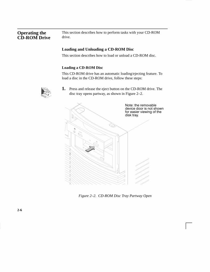
This CD-ROM drive has an automatic loading/ejecting feature. Toload a disc in the CD-ROM drive, follow these steps:
1. Press and release the eject button on the CD-ROM drive. Thedisc tray opens partway, as shown in Figure 2–2.
������������������ ������� ���������������� ��� � �������� ��������
Figure 2–2. CD-ROM Disc Tray Partway Open
Operating theCD-ROM Drive

2-7
2. Gently pull the disc tray fully open.
3. Hold the disc by the edges with the label side up and place it inthe disc tray as shown in Figure 2–3.
Figure 2–3. Placing the CD-ROM Disc in the Disc Tray
4. Press down gently on the center of the CD-ROM disc to makesure it is seated on the disc tray hub, shown in Figure 2–3.

2-8
5. Gently push the disc tray in until it is closed, as shown in Figure 2–4.
Figure 2–4. Disc Tray Closed

2-9
Unloading a CD-ROM Disc
To unload a disc from the Disc Tray, follow these steps:
1. Press and release the eject button on the CD-ROM drive. Thedisc tray opens approximately 1 inch, as shown in Figure 2–5.
Figure 2–5. CD-ROM Disc Tray Partway Open
2. Gently pull the disc tray fully open.

2-10
3. Grasp the disc by the edges and lift it out of the disc tray, asshown in Figure 2–6. Be careful to touch only the edges of thedisc.
Figure 2–6. Removing the CD-ROM Disc From the Disc Tray

2-11
4. Gently push the disc tray in until it is closed, as shown in Figure 2–7.
Figure 2–7. Disc Tray Closed
Verifying the CD-ROM Drive Operation
To verify that your workstation can communicate with the CD-ROMdrive, follow these steps:
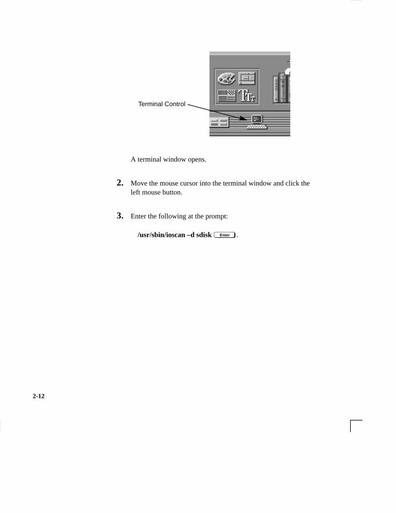
1. Click on the Terminal Control on the Front Panel of yourWorkspace.
The ioscan utility verifiesthe configuration of alldrives.
2-12
Terminal Control
A terminal window opens.
2. Move the mouse cursor into the terminal window and click theleft mouse button.
3. Enter the following at the prompt:
/usr/sbin/ioscan –d sdisk Enter .

2-13
After a few moments the ioscan utility lists all of the SCSI I/Odevices it could find. The list appears similar to the following:
H/W Path Class Description
============================================
bc
8 bc I/O Adapter
8/0 ext_bus GSC built-in Fast/Wide SCSI Interface
8/0.0 target
8/0.0.0 disk QUANTUM LPS1080WD
8/0.5 target
8/0.5.0 disk DEC DSP3210SW
8/0.6 target
8/0.6.0 disk DEC DSP3210SW
8/12 ba Core I/O Adapter
8/12/5 ext_bus Built-in SCSI
8/12/5.2 target
8/12/5.2.0 disk TOSHIBA CD-ROM XM-4101TA
8/12/5.4 target
8/12/5.4.0 disk SEAGATE ST3600N
8/12/5.6 target
8/12/5.6.0 disk MICROP 2112
10 bc I/O Adapter
10/12 ext_bus GSC add-on Fast/Wide SCSI Interface
10/12.4 target
10/12.4.0 disk SEAGATE ST31200W
If ioscan does not see your CD-ROM drive it returns the follow-ing message:
ioscan: No hardware found
If you receive this message, go to Chapter 6, “Solving Prob-lems.”
2-14
Using Device Files
Device files are special files that tell your system which pathway touse through the system hardware when communicating with a specificdevice and what kind of device it is.
To determine what device files are available for use with your CD–ROM drive, use the following procedure:
NOTICE: The device file names will depend on the nam-ing conventions of your particular system. See“SCSI ID and Device File Information for HP-UX 10.20 or Later” in Chapter 1 of this book.
1. In a terminal window, enter the following command:
sam Enter
2. The System Administration Manager (SAM) window opens.Double–click on Peripheral Devices –>.
3. The Peripheral Devices window opens. Double–click on CD–ROM Drives –>.
4. The CD–ROM Drives window opens.
5. In the list of CD–ROM drives, click on the desired CD–ROMdrive to select it.
6. From the Actions menu, click on Show Device Files.A window opens with a list of the device files for the selectedCD–ROM drive with an explanation of each one.
2-15
To access information on a CD-ROM disc, you must first mount thedisc. This applies to file system information only. If you wish to loada music CD, for example, you would not need to mount the disc.Mounting a disc with file system information on it gives the disc apathname that allows your workstation to communicate electronicallywith it. You must unmount the CD-ROM disc before removing itfrom the drive.
CAUTION: To use a CD-ROM disc as a mounted file sys-tem, you must mount the CD-ROM disc everytime you load it into the drive. You must alsounmount the CD-ROM disc every time you unload it from the drive. Failure to mount orunmount a disc can cause a system error condi-tion and can also require rebooting the system.
The procedures in this chapter require you to log in as root. If youcannot log in as root, contact your system administrator.
Mounting a CD-ROM Disc Using SAM
Use the following procedure to mount a CD-ROM disc:
1. Log in as root. If you need information on logging in or settingup a user account, see Using Your HP Workstation.
2. Load the CD-ROM disc into the disc tray and gently push thetray into the drive.
3. In a terminal window, enter the following command:
sam Enter
4. The System Administration Manager window opens. Double–click on Peripheral Devices–>.
Mounting andUnmounting a CD-ROM Disc
SAM (System Adminis-tration Manager) is a util-ity that performs systemadministration tasks us-ing a windows graphicaluser interface.

2-16
5. The Peripheral Devices window opens. Double–click on Disksand File Systems–>.
6. The Disks and File Systems window opens. Double–click onCD–ROM, Floppy, and Hard Disks.The following screen message appears:
Scanning the system’s hardware...
The CD–ROM, Floppy, and Hard Disks window opens con-taining a list of drives currently configured on thie system.Disks that are unmounted have the word ”unused” in the Usecolumn.
7. From the Actions menu, click on Add a Hard Disk Drive.
8. The Select a Disk to Add... window opens with a list of unuseddisks. Highlight the CD-ROM disc you want to mount.
9. Click on O K .
10. The Set Disk Usage and Options... window opens. Select FileSystem and click on O K .
11. The following screen messages appear:
Task started.
Creating the device file...Mounting file system...Modifying “/etc/checklist”...Task completed.
2-17
Click on O K .
Now you can access the CD-ROM disc as you would any othermounted file system.
Unmounting a CD-ROM Disc Using SAMUse the following procedure to unmount a CD-ROM disc:
NOTICE: Before you unmount a CD-ROM disc, makesure that your working directory (the directoryin which a relative path name search begins) isset to some directory other than the one underwhich the disc was mounted.
CAUTION: If you wish to use a CD-ROM disc as amounted file system, you must mount the CD-ROM disc every time you load it into the drive.You must also unmount the CD-ROM disc every time you unload it from the drive. Failureto mount or unmount a disc may cause a systemerror condition and may also require rebootingthe system.
1. Log in as root. If you need information on logging in or settingup a user account, see Using Your HP Workstation.
2. In a terminal window, enter the following command:
sam Enter
3. The System Administration Manager window opens. Double-click on Peripheral Devices –>.
4. The Peripheral Devices window opens. Double-click on Disksand File Systems –>.

2-18
5. The Disks and File Systems window opens. Double-click onCD-ROM, Floppy, and Hard Disks.
The following screen message appears:
Scanning the system’s hardware...
The CD-ROM, Floppy, and Hard Disks window opens con-taining a list of drives currently configured on this system.
6. Highlight the disc you want to unmount and click on Remove aHard Disk Drive from the Actions menu.
7. A window with the following message opens:
Do you want to remove the disk?
Click on Yes . The system reboots.
8. Press the eject button on the CD-ROM drive and remove theCD-ROM disc from the disc tray.

2-19
Reading the Busy Light
The CD-ROM busy light shows the status of the drive during the selftest and during activity with the host system.
The CD-ROM drive performs the self test when one of the followinghappens:
• You load a disc and close the Disc Tray.
• You turn on the workstation with a disc already loaded in theCD-ROM drive.
For the self test, the busy light operates in the following sequence:
1. Light On – The busy light goes on when the disc loads intothe drive.
2. Light Flashing – The light flashes six times while a read testis performed on the disc.
3. Light Off – The light goes off when the self test is com-plete.
The busy light stays on after the self test when one of the followingconditions exist:
• A defective disc
• A disc insertion error (for example, an upside-down disc)
• No disc present
The busy light goes off when one of the following conditions exist:
• A CD-ROM drive power failure exists.
• The drive is idle on the SCSI bus.
The busy light flashes during normal activity with the system.

2-20
Troubleshooting
If you have trouble with any of these procedures for using your CD-ROM drive, see Chapter 6 of this book, “Solving Problems.”
3-1
Chapter 3
Using Your DDS Tape Drive
• DDS tape drive and data cassette descriptions
• Setting the write-protect tab on a data cassette
• Operating the DDS tape drive
• Loading and unloading a data cassette
• Using device files
• Archiving data in compressed and non-compressed mode
• Troubleshooting
• Ordering information
3-2
This chapter describes how to perform tasks that archive to and trans-fer data from the optional DDS tape drive. It also describes how tomaintain and care for the drive. We assume the DDS tape drive is setto the factory default address of SCSI ID 3.
The instructions in this chapter assume you are using the HP-UX version 10.20 or later operating system with the HP VUE version 3.0interface.
CAUTION: Use only data cassettes labeled DDS (DigitalData Storage) cassettes. Never use audio cas-settes labeled DAT (Digital Audio Tape) in yourDDS-format drive.

3-3
This section describes basic information needed for using your DDStape drive and data cassettes. Depending on your configuration, yourDDS drive may be a DDS-DC drive, or a DDS-2 drive.
NOTICE: In most cases, the information for using thesedrives is the same; however, in a few instances(such as the LED codes), the information dif-fers for each drive. For the purposes of this dis-cussion, wherever we refer to simply the“DDS” drive, that information is for bothdrives. Whenever the information differs, wewill specify whether the information refers tothe DDS-DC or the DDS-2 drive.
DDS Drive
Your DDS tape drive is a 3 1/2-inch form factor DDS tape drive withdata compression and a SCSI interface. It conforms to the DDS for-mat standard for storing computer data, and incorporates a data com-pression capability. It’s a high-capacity, high transfer-rate device fordata storage on tape.
Controls and IndicatorsFigure 3–1 shows the LEDs and eject button of the DDS drive.
Cassette LED Drive LED Eject Button
Figure 3–1. DDS Drive Controls and Indicators
DDS Tape Driveand Data CassetteDescriptions

3-4
LEDs – DDS-DC DriveThis section describes the LED codes that are displayed.
The front panel has two colored LEDs: the Cassette Light and theDrive Light. A green light indicates normal operation, and an amberlight indicates a warning condition. Pulsing shows activity betweenthe drive and the SCSI bus.
If the Cassette Light (left LED) shows steady amber, it means that thecassette is write-protected. If the Drive Light (right LED) showssteady amber, this indicates a fault condition. Table 3–1 lists the LEDcodes and their meanings.
Table 3–1. LED Display Codes – DDS-DC Drive
Cassette Drive MeaningLight Light
Cassette (un)loading
Cassette loaded/online
Cassette loaded/activity
Cassette loaded/offline
Write-Protect States
Error States
Cassette (un)loading
Cassette loaded/online
Cassette loaded/activity
Cassette loaded/offline
Media wear (caution)
High humidity
Self-test (normal)
Self-test (failure)
Key
OFF
Green
Amber
Pulsing Green
Pulsing Amber
Pulsing Green and Amber
LEDs (light emittingdiodes) indicate differentactivities or problemsthat occur with yourworkstation hardware

3-5
LED Warning Conditions – DDS-DC DriveThe following sections describe actions to take if the LEDs indicate awarning condition.
High HumidityIf the LEDs display the high humidity signal, the humidity is too highand the drive does not perform any operations until the humiditydrops.
Self-Test (Failure)If the LEDs display the self-test (failure) signal, a fault was diagnosedduring the self tests. Note the pattern of the pulses and contact yourlocal service representative.
Media Wear (Caution)Hewlett-Packard DDS drives continually monitor the number of er-rors they have to correct when reading and writing to a tape to deter-mine tape wear and tape head cleanliness. If excessive tape wear ordirty tape heads are suspected, the drive warns you by displaying theMedia Wear (Caution) signal on the LED indicators.
If the LED indicators on your DDS-format drive display the MediaWear (Caution) condition, follow this procedure:
1. Check the system console for any tape error messages. A harderror during a read or write operation may have occurred.
2. Clean the heads with a cleaning cassette (HP92283K) as de-scribed in the “Cleaning the Tape Heads” section, later in thischapter.
3. Repeat the operation you performed when the Media Wear (Cau-tion) signal displayed. If the Media Wear (Caution) signal stilldisplays, then the data cassette should be replaced.

3-6
4. If you are performing a backup from disk to tape, discard thedata cassette and back up your files using a new data cassette.
5. If you are performing a restore from tape to disk, complete therestore, then discard the data cassette and back up the files to anew data cassette.
LEDs – DDS-2The front panel has two colored LEDs: the Tape Light and the Clean/Attention Light. The Tape Light flashes green to show activity (load-ing, unloading, reading, and writing). Steady green means a cartridgeis loaded.
The Clean/Attention Light flashes amber to indicate head cleaning isneeded or a cartridge is near the end of its life. Steady amber means ahard fault.
Table 3–2. LED Display Codes – DDS-2 Drive
Tape Clean/ MeaningLight Attention
Activity – load or unload
Activity – read or write
Cartridge loaded
Cleaning needed
Fault
Key
OFF
Steady Green
Steady Amber
Flashing Green1/2 sec on, 1/2 sec off
Flashing Amber1/2 sec on, 1/2 sec off
Fast Flash Green1/4 sec on, 1/4 sec off
Any
Any
3-7
Data Cassettes
Media LifeHP DDS data cassettes are currently specified to 2000 passes overany part of the tape under optimal environmental conditions (50%relative humidity, 22 degrees C). During a tape operation, any onearea of the tape may have multiple passes over the heads. This trans-lates into approximately 200 to 300 backups or restores.
Under certain conditions, the life of your data cassette is less. Replaceyour data cassettes after 100 backups or restores if your operatingconditions meet any of the following criteria:
• The relative humidity in your operating environment is consis-tently less than 50%.
• You know that the backup software you are using makes multi-ple passes over sections of the tape during backups or restores.
• You notice that when you do backups and restores the tape stopsand starts frequently.
Cleaning the Tape HeadsClean the heads of your tape drive after every 25 hours of tape driveuse or if the Media Wear (Caution) signal is displayed on the LED.
NOTICE: Only use HP Cleaning Cassettes (HP92283K)to clean the tape heads. Do not use swabs orother means of cleaning the tape heads.
Follow this procedure to clean the tape heads:
1. Insert the cleaning cassette into the drive. The tape automaticallyloads the cassette and cleans the heads. At the end of the clean-ing cycle, the drive ejects the cassette.
2. Write the current date on the label on the cleaning cassette sothat you know how many times you have used it. Discard thecleaning cassette after you have used it 25 times.
3-8
Media RestrictionsIf you interchange media between other HP workstation DDS tapedrives, note that data cassettes with compressed data can only be readby tape drives that have data compression capabilities. This includesdata cassettes that contain both compressed and noncompressed data.
Setting the Write-Protect Tab on a Data Cassette
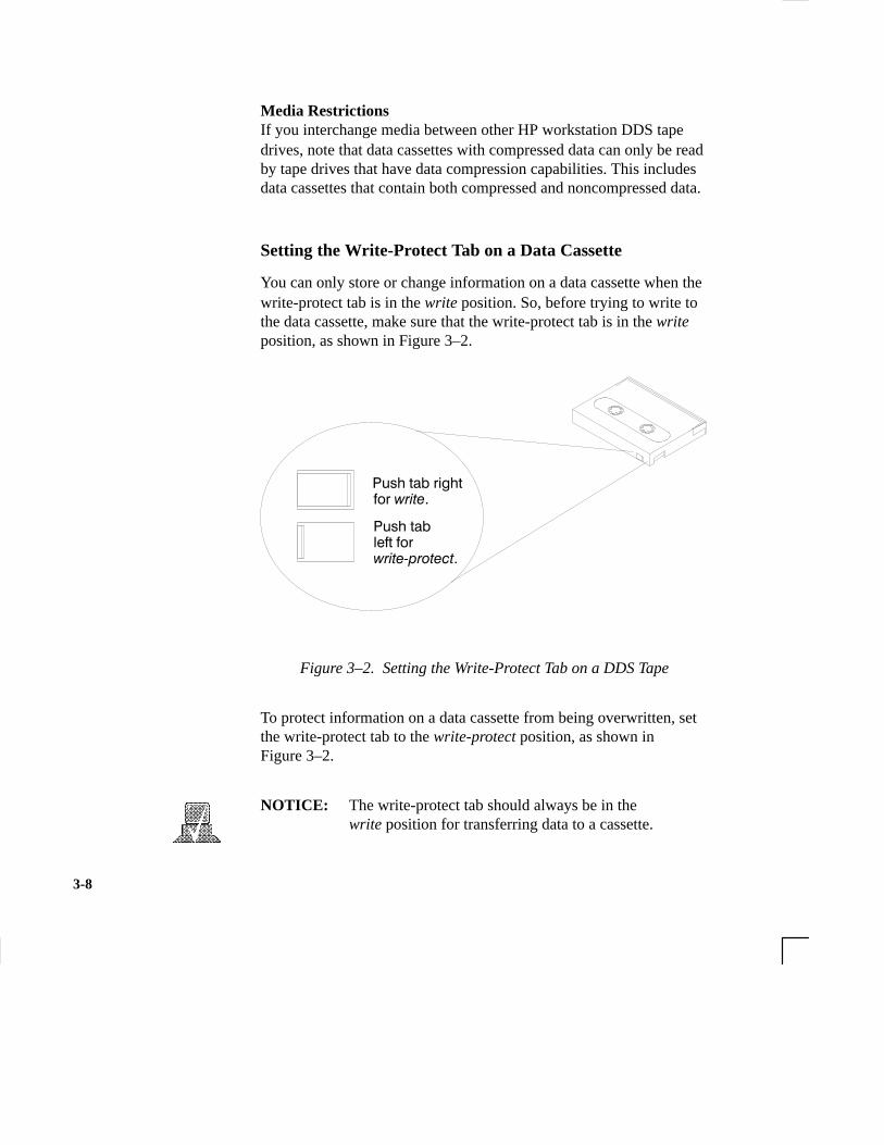
You can only store or change information on a data cassette when thewrite-protect tab is in the write position. So, before trying to write tothe data cassette, make sure that the write-protect tab is in the writeposition, as shown in Figure 3–2.
���� ���� ���� � ������
���� ��������� �� �������������
Figure 3–2. Setting the Write-Protect Tab on a DDS Tape
To protect information on a data cassette from being overwritten, setthe write-protect tab to the write-protect position, as shown in Figure 3–2.
NOTICE: The write-protect tab should always be in thewrite position for transferring data to a cassette.
3-9
This section describes how to perform tasks with your DDS tapedrive.
Loading and Unloading a Data Cassette
Follow these steps to load and unload a data cassette in the DDS tapedrive:
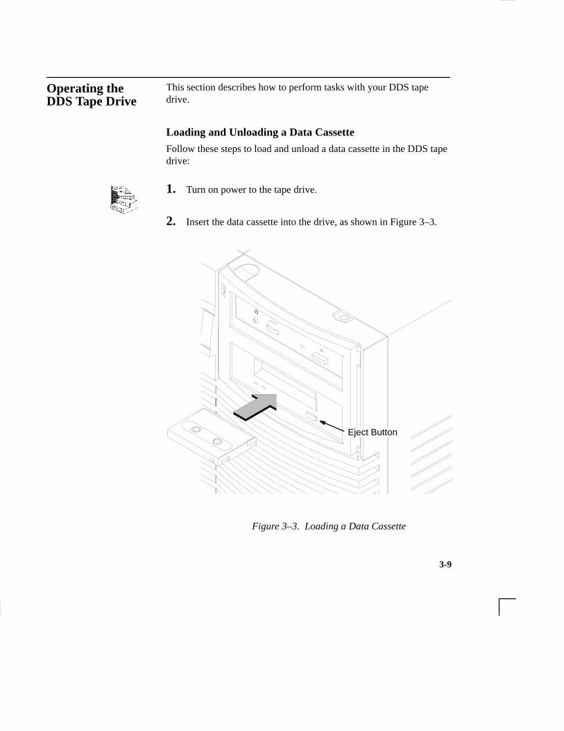
1. Turn on power to the tape drive.
2. Insert the data cassette into the drive, as shown in Figure 3–3.
Eject Button
Figure 3–3. Loading a Data Cassette
Operating theDDS Tape Drive

3-10
3. Push the data cassette about three quarters of the way into thedrive. The drive automatically pulls the data cassette the rest ofthe way in. When the LEDs on the front of the drive stop flash-ing, the drive has loaded the data cassette.
4. To remove the data cassette, press and release the eject button onthe front of the drive, as shown in Figure 3–3. The LEDs on thedrive flash on and off. Ten to twenty seconds later, the data cas-sette slides partway out of the drive. Remove the cassette fromthe drive.
Verifying the DDS Tape Drive Operation
Type the following:
/usr/sbin/ioscan –d stape Enter

3-11
After a few moments the ioscan utility returns a message similar tothe following:
H/W Path Class Description============================================ bc 8 bc I/O Adapter8/12 ba Core I/O Adapter8/12/5 ext_bus Built-in SCSI8/12/5.3 target 8/12/5.3.0 tape HP HP35480A
If ioscan does not see your tape drive it will return the following mes-sage:
ioscan: No hardware found
If you receive this message, go to Chapter 6, “Solving Problems.”

3-12
Using Device Files
Your system has four default device files for use with your tape drive:two device files for noncompressed mode and two device files forcompressed mode. If you use these device files, you do not need tocreate any device files.
If the SCSI address of your tape drive is not set to the factory defaultof SCSI ID 3, you must create a device file, then substitute the path-name of your device file in the examples that follow. Refer to the Sys-tem Administration Tasks manual for information on how to create adevice file.
NOTICE: The device file names depend on the namingconventions of your particular system. See“SCSI and Device File Information for HP-UX10.20 or Later” in Chapter 1 of this book.
Device Files — No Data CompressionYour system has two device files for using your tape drive with datacompression turned off. The device files are named /dev/rmt/3m and/dev/rmt/3mn, and are set for SCSI ID 3.
If you use the /dev/rmt/3m device file, the tape drive rewinds thedata cassette every time the system releases the drive from its control.
If you use the /dev/rmt/3mn device file, the drive does not rewindthe data cassette. The tape stays where it was after the last operation.
If you use these device files, you do not need to create any devicefiles.
Determining Available Device Files
1. In a terminal window, enter the following command:
sam Enter
Device files are specialfiles that tell your systemwhich system hardwarepathway to use whencommunicating with aspecific device and whatkind of device it is.
3-13
2. The System Administration Manager window opens. Double–click on Peripheral Devices –>.
3. The Peripheral Devices window opens. Double–click on TapeDrives –>.
4. The Tape Drives window opens.
5. In the list of tape drives, clock on the desired tape drive to selectit.
6. From the Action menu, click on Show Device Files.
A window opens with a list of the device files for the selectedtape drive with an explanation of each one.

3-14
Device Files — Data CompressionIf you wish to use the data compression feature, use the device files/dev/rmt/3hc and /dev/rmt/3hcn, which are set for SCSI ID 3.
If you use the /dev/rmt/3hc device file, the tape drive compresses thedata and rewinds the data cassette every time the system releases thedrive from its control.
If you use the /dev/rmt/3hcn device file, the drive compresses thedata, but does not rewind the data cassette. The tape stays where itwas after the last operation.
If you use these device files, you do not need to create any devicefiles.
Archiving Data in Compressed and Noncompressed Mode
This section describes how to transfer data to and from a DDS- for-mat data cassette (saving and restoring) using the HP-UX tar com-mand and your tape drive’s device file.
NOTICE: Before using your DDS-format tape drive toback up your file system, make sure you readthe “Media Interchangeability Restrictions”section later in this chapter.
The tar (tape file archiver) command allows you to save files to adata cassette, restore files from a data cassette to your system, or listfiles on your data cassette.
The tar (tape file archiv-er) command saves filesto a data cassette, re-stores files from a datacassette, or lists files ona data cassette.

3-15
Writing to a Data Cassette
Use the following instructions to save files to a data cassette:
1. Check that the write-protect tab on the data cassette is in thewrite position.
2. Load the data cassette into the tape drive.
3. In a terminal window, enter the following command line to writeto the tape:
tar –cvf /dev/rmt/devicefile pathname Enter
where devicefile is one of the device files listed from sam, andpathname is the pathname of the file or directory containing filesthat you want to write to the tape. To use the data compressionmode, use one of the device file names that sam listed as sup-porting compression. .
Restoring Files from a Data Cassette to Your System
Use the following instructions to restore files from a data cassette toyour system:
1. Load the data cassette into the tape drive.
2. In a terminal window, use cd to change to the directory in whichyou want the files to reside.
3. Enter the following command line:
tar –xvf /dev/rmt/devicefile pathname Enter

3-16
where devicefile is one of the device files listed from sam, andpathname is the pathname of the file or directory containing filesthat you want to restore from the tape. If pathname is not speci-fied, everything on the data cassette is restored. To use the datacompression mode, use one of the device file names that samlisted as supporting compression..

3-17
Listing the Files on a Data Cassette
Use the following instructions to list the files on a data cassette:
1. Load the data cassette into the tape drive.
2. In a terminal window, enter the following command line to re-ceive a file listing of the data cassette:
tar –tvf /dev/rmt/devicefile Enter
where devicefile is one of the device files listed from sam. If thetape was made with data compression, use on the the device filenames that sam listed as supporting compression.
3-18
Further Command Information
For additional information on using tar and a complete list of thecommand arguments, refer to the tar man page by typing the follow-ing:
man tar Enter
You may also communicate with the tape drive with the cpio, ftio,mt, and fbackup commands. For more information on these com-mands, enter the following in a terminal window:
man command Enter
Media Interchangeability Restrictions
If you interchange media between DDS-format tape drives, the fol-lowing two restrictions apply to the media:
• Data cassettes with compressed data can only be read by tapedrives that have data compression capabilities, such as the tapedrive (part number C1504–67201) found in Kit A2275A #AHS.
• Full height (5 1/4-in) DDS-format tape drives (models HP35470A and HP35480A) can get 1.3 GB and can read or writeto 60-meter data cassettes only, if they are not using data com-pression. With data compression, these drives can get 2 GB andcan read or write to 90-meter cassettes.
Troubleshooting
If you have trouble with any of these procedures for using your DDStape drive, see Chapter 6 of this book, “Solving Problems.”
The man utility looks upman pages on the sys-tem.
3-19
Ordering Information
To order Hewlett-Packard data cassettes and cleaning cassettes for usein your DDS tape drive, use the following order numbers:
• HP92283A Box of five 60–meter DDS data cassettes
• HP92283B Box of five 90–meter DDS data cassettes
• HP92300A Box of five 120-meter DDS data cassettes(for DDS-2 drive only)
• HP92283K Package of two cleaning cassettes
• HP92283L Lockable storage box for 12 cassettes
CAUTION: Use only data cassettes labeled as DDS (Digital Data Storage) cassettes. Never use audio cassettes labeled DAT (Digital AudioTape) in your DDS-format drive.

4-1
Chapter 4
Using Your 3.5-Inch Floppy Disk Drive
• Setting the write-protect tab on a diskette
• Inserting and removing a diskette
• Verifying the floppy disk drive configuration
• Using device files
• Floppy disk drive device file
• Formatting a new diskette
• Transferring data to and from a floppy diskette
• Configuring the floppy driver
• Troubleshooting
• Ordering information
4-2
This chapter describes how to perform tasks that allow you to archiveto or transfer data from the optional 3.5-inch floppy disk drive.
The instructions in this chapter assume you are using the HP-UX version 10.20 or later operating system with the HP VUE version 3.0interface.
NOTICES: When examples of user input are given in thischapter, enter them at the command-line promptin an HP VUE terminal window or HP-UXshell.
Some procedures in this chapter require you tolog in as root. If you cannot log in as root, con-tact your system administrator.

4-3
This section describes basic information needed for using your floppydiskettes.
Setting the Write-Protect Tab on a Diskette
You can only store or change information on a diskette when the write-protect tab is in the write position. So, before trying to write tothe diskette, make sure that the write-protect tab is in the write posi-tion, as shown in Figure 4–1.
Push tab upfor write.
Push tab down for write-protect.
Figure 4–1. Setting the Write-Protect Tab on a Floppy Diskette
To protect files on a diskette from being overwritten, set the write-protect tab to the write-protect position.
NOTICE: The write-protect tab should always be in thewrite position for formatting a new diskette andtransferring data to a diskette.
Using the FloppyDiskette

4-4
Inserting and Removing a Diskette
Follow these steps to insert and remove a diskette from the floppydisk drive:
1. Insert the diskette into the drive, as shown in Figure 4–2.
Eject Button
Figure 4–2. Inserting and Removing a Floppy Diskette
2. Push the diskette into the floppy drive until it clicks into place.
3. To remove the diskette, push the eject button (see Figure 4–2),then take out the diskette.

4-5
This section describes how to perform tasks with your 3.5-inch floppydisk drive.
Verifying the Floppy Drive Configuration
To verify that your workstation can communicate with the floppydrive, use the ioscan command in a terminal window to see whichdevices are currently in use on your system:
1. Enter the following at a command prompt:
/usr/sbin/ioscan –d sflop Enter
After a few moments the ioscan utility lists all of the SCSIfloppy I/O devices it could find. The list appears similar to thefollowing:
H/W Path Class Description
============================================
bc
8 bc I/O Adapter
8/12 ba Core I/O Adapter
8/12/5 ext_bus Built-in SCSI
8/12/5.0 target
8/12/5.0.0 disk TEAC FC-1 HF 07
If ioscan does not see your floppy drive it returns the followingmessage:
ioscan: No hardware found
If you receive this message, go to Chapter 6, “Solving Prob-lems.”
Operating theFloppy Drive
The ioscan utility verifiesthe configuration of alldrives.

4-6
If the floppy driver is not configured, ioscan returns the follow-ing message:
ioscan: Device driver scsifloppy is not in the kernel
If you receive this message, go the the section, “Configuring theFloppy Driver” later in this chapter for information on addingthe scsifloppy driver to the HP-UX kernel configuration.
Using Device Files
Device files are special files that tell your system which pathway touse through the system hardware when communicating with a specificdevice and what kind of device it is.
NOTICE: The device file names depend on the namingconventions of your particular system. See“SCSI ID and Device File Information for HP-UX 10.20 or Later” in Chapter 1 of this book.
If you set the SCSI address of your floppy drive to a value other than0, you must create a device file for it. Refer to the System Administra-tion Tasks manual for information on how to create a device file.
To determine what device files are available for use with your floppydrive, use the following procedure:
1. In a terminal window, enter the following command:
sam Enter
2. The System Administration Manager window opens. Double–click on Disks and File Systems–>.
3. The Disk and File Systems window opens.

4-7
4. In the list of drives, click on the floppy drive listing to select it.
5. From the Actions menu, click on View More Information.
A window opens with a list of information for the floppy drive,inlcuding the device files.

4-8
Formatting a New Diskette
You must always format a new floppy diskette with the mediainitutility before using it. To format a new floppy diskette follow thesesteps:
1. Log in as root.
2. Make sure that the write-protect tab on the floppy diskette is inthe write position, as shown in Figure 4–1.
3. Insert the diskette into the floppy disk drive.
4. In a terminal window, execute mediainit with an interleave of 2by entering the following:
mediainit –i 2 devicefile Enter
where devicefile is the device file as listed by sam.
Transferring Data To and From a Floppy Diskette
This section describes how to transfer data to and from your floppydiskette (saving and restoring) using the HP-UX tar command withyour floppy drive’s device file.
You need to set the write protect tab to the write position to transferdata to the diskette. The write-protect tab can be in either positionwhen restoring data from a diskette or listing the files on a diskette.
The tar (tape file archiv-er) command saves filesto a floppy diskette, re-stores files from a floppydiskette, or lists files ona floppy diskette.

4-9
Saving Files to a Floppy Diskette
Use the following instructions to save files to a floppy diskette:
1. Check that the write-protect tab on the floppy diskette is in thewrite position.
2. Load the formatted floppy diskette into the disk drive.
3. In a terminal window enter the following command line to writeto the diskette:
tar –cvf devicefile pathname Enter
where devicefile is the device file as listed by sam and pathnameis the pathname of the file or directory containing files that youwant to write to the diskette.
Restoring Files from a Floppy Diskette to Your System
Use the following instructions to restore files from a floppy disketteto your system:
1. Load the floppy diskette into the disk drive.
2. In a terminal window, use the cd command to change to the di-rectory you want the files to reside in:
cd directory_path Enter
where directory_path is the pathname of the directory.
3. Enter the following command line:

4-10
tar –xvf devicefile pathname Enter
where devicefile is the device file as listed by sam and pathnameis the pathname of the file or directory containing files that youwant to restore from the diskette. If you do not specify path-name, everything on the floppy diskette is restored.
Listing the Files on a Floppy Diskette
Use the following instructions to list the files on a floppy diskette:
1. Load the floppy diskette into the disk drive.
2. In a terminal window, enter the following command line:
tar –tvf devicefile Enter
where devicefile is the device file as listed by sam
All files on the floppy diskette are listed.
For More Information
For more information on using tar and a complete list of the com-mand arguments, refer to the tar man page by typing the following ina terminal window:
man tar Enter
You can mount the floppy drive as a file system using the SAM util-ity. Be sure to unmount the drive before removing it as a file system.For more information about how to mount and unmount the floppydrive, see the manual Using HP-UX (B2910–90001).
For more information on copying data to or from your system to othermedia, including your floppy diskette, refer to the cpio man page bytyping the following in a terminal window:
The man utility looks upman pages on the sys-tem.

4-11
man cpio Enter
For more information on copying to or from DOS files, refer to thedoscp man page by typing the following in a terminal window:
man doscp Enter
For more information on listing DOS directories, refer to the doslsman page by typing the following in a terminal window:
man dosls Enter
For more information on using your floppy disk drive and floppy dis-kettes, refer to the floppy man page by typing the following in a ter-minal window:
man floppy Enter
For more information on using the mediainit command, refer to themediainit man page by typing the following in a terminal window:
man mediainit Enter

4-12
Configuring the Floppy Driver
If you reload software or rebuild the Instant Ignition system on yourworkstation, you need to reconfigure the HP-UX Kernel to add thefloppy driver. Use the SAM utility to add the SCSI flexible disk driv-er and build a new HP-UX kernel.
For more information about how to reconfigure the kernel usingSAM, see the following manuals:
• System Administration Tasks HP 9000 Series 700 Computers(B2355–90040)
• Using HP-UX (B2910–90001)
Troubleshooting
If you have trouble with any of these procedures for using yourfloppy disk drive, see Chapter 6 of this book, “Solving Problems.”
Ordering Information
To order Hewlett-Packard micro flexible diskettes for use in your3.5-inch floppy disk drive, use the following order number:
HP–92192X High-Density Micro Flexible Disks(1.44MB Formatted Capacity) – boxof ten diskettes

5-1
Chapter 5
Solving Problems
• Common problems and solutions
• Dealing with a boot failure
• Memory failures
• LCD-indicated problems
• Running system verification tests
5-2
This chapter contains information to help you determine what’swrong with your system when you have problems. If you have aproblem that isn’t listed in this chapter, or if your problem persists,contact your designated service representative. When calling for ser-vice, always have your system’s model number and serial numberready.
The instructions in this chapter assume you are using the HP-UX version 10.20 or later operating system with the HP VUE version 3.0graphical interface. If your system is configured with the HP CDEgraphical user interface, use command line options in a terminal win-dow to perform tests.

5-3
The tables in this section list common problems you may encounterwith your workstation. The tables also tell you what to do to helpsolve the problems.
Table 5–1. Problems Powering Up the System
Problem Solution
The power LEDdoesn’t light.
The power LEDlights, but the screenis blank or flickers
LCD messages
Make sure all ac power cables areconnected securely to the system.
Make sure the power cord is pluggedinto a working ac outlet.
Make sure the power switch is set tothe ON position.
Press the brightness control on themonitor to adjust it. If the screen isstill blank, turn off the system andmonitor power switches. When thesystem is completely powered off,check the video cable connections.
Go to the section “Changing YourMonitor Type” in Appendix B for in-formation about displaying and settingyour workstation’s monitor configura-tion.
See “LCD-Indicated Problems” laterin this chapter.
If problems persist, contact your system administrator or callyour designated service representative.
Common Problems andSolutions

5-4
Table 5–2. Problems Loading and Booting the Operating System
Problem Solution
The power LED islit, and text appearson the screen, butmore than two min-utes have passedwith no sign of system activity.
The system stops orhangs while booting.
Make sure that all SCSI devices are setto the proper SCSI ID. (See AppendixC for default SCSI ID settings.)
Check that all SCSI devices are cor-rectly cabled. Check that the SCSI busis correctly terminated. (See AppendixC for information on SCSI cabling andtermination.)
Follow the instructions in “DealingWith a Boot Failure,” later in thischapter.
If problems persist, contact your system administrator or callyour designated service representative.

5-5
Table 5–3. Problems with the 802.3 Network
Problem Solution
Can’t reach othersystems on the net-work. Applicationsthat rely on the net-work won’t run.
Check the network connector on theback of the system unit. Make surethat the network cable or transceiver isfastened securely to the connector.
If problems persist, contact your system administrator or callyour designated service representative.
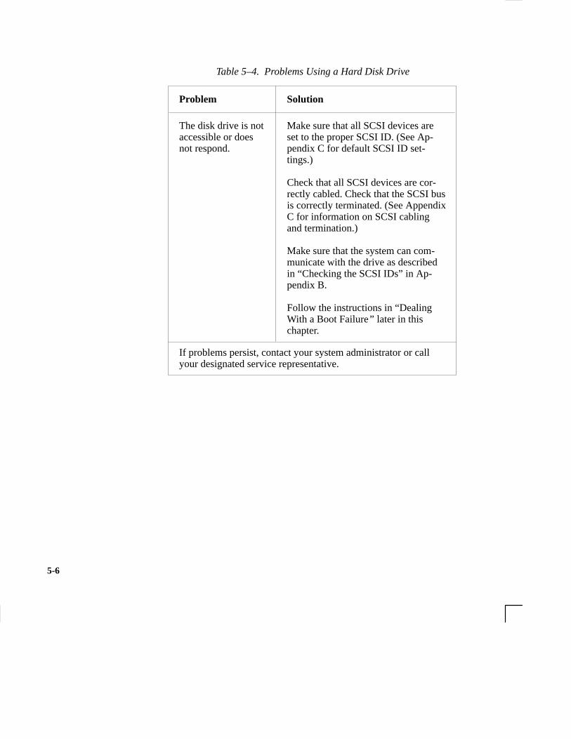
5-6
Table 5–4. Problems Using a Hard Disk Drive
Problem Solution
The disk drive is notaccessible or doesnot respond.
If problems persist, contact your system administrator or callyour designated service representative.
Make sure that all SCSI devices areset to the proper SCSI ID. (See Ap-pendix C for default SCSI ID set-tings.)
Check that all SCSI devices are cor-rectly cabled. Check that the SCSI busis correctly terminated. (See AppendixC for information on SCSI cablingand termination.)
Make sure that the system can com-municate with the drive as describedin “Checking the SCSI IDs” in Ap-pendix B.
Follow the instructions in “DealingWith a Boot Failure” later in thischapter.

5-7
Table 5–5. Problems Using the CD-ROM Drive
Problem Solution
The CD-ROM drivedoes not respond tocommands.
Re-enter the commands and makesure that you have typed them cor-rectly.
Make sure that the system can com-municate with the drive as describedin “Checking the SCSI IDs” in Appendix B.
Follow the instructions in the sectionentitled “ Running System Verifica-tion Tests” later in this chapter toverify that the CD-ROM drive isfunctioning properly.
If problems persist, contact your system administrator or callyour designated service representative.

5-8
Table 5–6. Problems Using the DDS Tape Drive
Problem Solution
The DDS tape drivedoes not respond tocommands.
Re-enter the commands and make surethat you have typed them correctly.
Make sure that you specified the cor-rect device file name for commandsthat require a device file name.
Make sure the write-protect tab is setto write if you are trying to copy datato a data cassette.
Make sure that the system can com-municate with the drive as describedin “Checking the SCSI IDs” in Ap-pendix B.
Follow the instructions in the sectionentitled “Running System VerificationTests” later in this chapter to verifythat the tape drive is functioning prop-erly.
If problems persist, contact your system administrator or callyour designated service representative.

5-9
Table 5–7. Problems Using the Floppy Disk Drive
Problem Solution
The floppy drivedoes not respond tocommands.
Re-enter the commands and make surethat you have typed them correctly.
Make sure that you specified the de-vice file /dev/rfloppy/c201d0s0 forcommands that require a device filename.
Make sure that the write-protect tab isset to write if you are trying to copydata to a floppy diskette.
Follow the instructions in the sectionentitled “ Running System VerificationTests” later in this chapter to verifythat the floppy drive is functioningproperly.
If problems persist, contact your system administrator or callyour designated service representative.

5-10
If your usual boot device (typically a disk) is not responding as itshould, you must try to boot from the disk (or another boot device) byselecting it manually.
To boot a device manually, follow these steps:
1. Follow the directions in “Accessing the Boot Console Interface,”in Appendix D of this book.
NOTICE: Your workstation automatically shuts down theoperating system before it terminates the power.
2. At the Main Menu prompt, type the following:
Main Menu: Enter a command or a menu > search ipl Enter
This causes your workstation to search exhaustively for bootable media.
3. Boot from one of the listed devices by typing the following atthe prompt:
Main Menu: Enter a command or a menu > boot device Enter
where device is the hardware path to the device, specified inmnemonic style notation, such as FWSCSI.5.0.
4. If your workstation still fails to boot, there is either somethingwrong with the file system or with the hardware. If you suspect afile system failure, see the manual Using HP-UX for help ondealing with file system failures. If you think that something iswrong with the hardware, continue reading this chapter for moretroubleshooting information.
Dealing with aBoot Failure
The search commandlooks for bootable mediaon your workstation.

5-11
J Class systems use Memory Page Deallocation, a feature that allowsthe system to provide information to the operating system aboutmemory failures.
HP-UX 10.20 uses Memory Page Deallocation information to mapout the failing memory areas, and continue normal operation. You canuse the command memrpt with the detail switch to obtain informa-tion about the Memory Page Deallocation Table (PDT) as well assingle bit errors logged by the system.
# /usr/sbin/sysdiag Enter
DUI >logtool Enter
LOGTOOL> memrpt detail Enter
NOTICE: You must be logged in as superuser to use thememrpt command.
To exit the sysdiag and logtool utilities, use the exit command.
The pdt can also be checked using the pdt command in the Servicemenu of the boot console handler. If a failing DIMM is replaced, usethe Service menu pdt clear command to clear out the PDT.
Memory Failures

5-12
Your workstation uses an LCD panel to display firmware/OS progresscodes. The codes, referred to as chassis codes, consist of one of themnemonics listed below, followed by a 4-digit hex number identify-ing the code module being executed. The mnemonics and their mean-ing are:
• FLT – A hardware error has been detected
• TEST – Hardware being tested
• INIT – Hardware being initialized
• SHUT – System being shutdown
• WARN – A non-optimal operating condition exists
• RUN – System is running operating system
During a normal boot sequence, a set of “windows” appear. In gener-al, the LCD display has the following format:
← � ��� �
← � ��� �
� � � � � � � ♥�����
�����������
ZZZZ > 4 character OSTAT
YYYY > 4 digit hex code
CPUXX > Functional CPUs in system
♥ > Heart beat
WWWWWWWWWWWWWWWW > Text Diagnostic Message
LCD-IndicatedProblems

5-13
The windows are as follows:
Window 1
When the system is hard booted, the LCD will be cleared and the fol-lowing message will be displayed for approximately 1 second. Thenthe processor dependent hardware (pdh) is verified.
Proceeding To <– line 1
Turn DC On <– line 2
Window 2
While the pdh is being verified, the following message is displayed:
ZZZZ YYYY <– line 1
Selftest Sys Bd <– line 2
Window 3
After the pdh is verified, the selftest is executed. The display changesto:
ZZZZ YYYY ♥ <– line 1 – ’ ♥ ’ flashes with Z Y field changeSelftest <– line 2
Window 4
When the selftest is complete, the message (once the console isfound) is:
ZZZZ YYYY CPUXX♥ <– line 1 – ’ ♥ ’ flashes with Z Y field changeAAAAAAAA console <– line 2
where AAAAAA is RS-232A, RS-232B, or GRAPHICS.

5-14
Window 5
When an attempt to boot is made, the following message is displayedonce IPL is successfully loaded and launched:
ZZZZ YYYY CPUXX♥ <– line 1 – ’ ♥ ’ flashes with Z Y field changeBBBBBBBBBBBBBBBB <– line 2
where BBBBBBBBBBBBBBBB is the model number (for example,9000/J200).
If the system encounters an FLT code while the system is booting, theFLT code is interpreted and one of the following messages is dis-played:
FLT CODE MESSAGES Meaning of X
1. Selftest Sys Bd2. Selftest cpu X (0 or 1)3. Selftest EISA X (0 to 4)4. Selftest DIMM XX (DIMM pair 0 to 7)5. Selftest Mem Sys6. Selftest Graph X (0 to 2)7. Unexp. Trap XX (0 to 28)8. HPMC occurred !
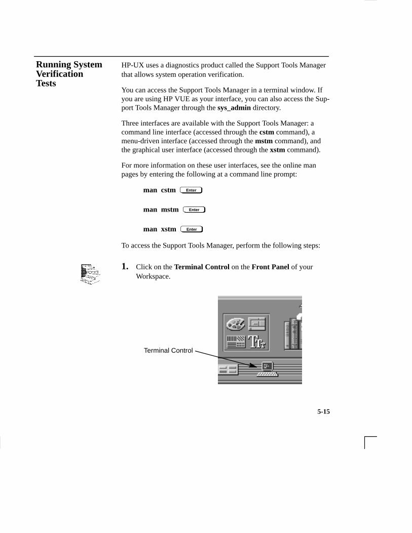
5-15
HP-UX uses a diagnostics product called the Support Tools Managerthat allows system operation verification.
You can access the Support Tools Manager in a terminal window. Ifyou are using HP VUE as your interface, you can also access the Sup-port Tools Manager through the sys_admin directory.
Three interfaces are available with the Support Tools Manager: acommand line interface (accessed through the cstm command), amenu-driven interface (accessed through the mstm command), andthe graphical user interface (accessed through the xstm command).
For more information on these user interfaces, see the online manpages by entering the following at a command line prompt:
man cstm Enter
man mstm Enter
man xstm Enter
To access the Support Tools Manager, perform the following steps:
1. Click on the Terminal Control on the Front Panel of yourWorkspace.
Terminal Control
Running SystemVerificationTests

5-16
A terminal window opens.
2. Move the mouse cursor into the terminal window and click theleft mouse button.
3. Enter the following at the prompt:
cstm Enter
The following screen appears:
Support Tool Manager Version A.01.00
Type ’help’ for a list of available commands.
CSTM>
At the CSTM> prompt, you can enter several commands. To seewhat commands are available, type the help command.
4. To verify the system operation, type the following at the CSTM>
prompt:
CSTM> verify all Enter
Messages similar to the following appear:
Verification has started on device (CPU).Verification has started on device (FPU).
CSTM>Verification of (FPU) has completed.CSTM>Verification of (CPU) has completed.
5. Press Enter to return to the CSTM> prompt after all test resultsare reported.

5-17
6. To exit the Support Tools Manager, type the following:
CSTM> exit Enter
If any tests failed, further diagnosis is necessary by qualified servicepersonnel. Contact your designated service representative.

A-1
Appendix A
Safety and Regulatory Statements
• Declaration of conformity
• Emissions regulations
• Emissions regulations compliance
• Datacom users statement
• Acoustics
• Electrostatic discharge (ESD) precautions
• Laser safety statements
• Warnings and cautions
This appendix contains safety and regulatory statements pertaining toyour J 280 workstation.
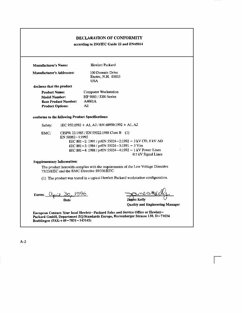
A-2

A-3
Federal Communications Commission (FCC)
This equipment has been tested and found to comply with the limitsfor a Class B digital device, pursuant to part 15 of the FCC Rules andthe Canadian Department of Communications. These limits are de-signed to provide reasonable protection against harmful interferencein a residential installation. This equipment generates, uses, and canradiate radio frequency energy and, if not installed and used in accor-dance with the instructions may cause harmful interference to radiocommunications. However, there is no guarantee that interference willnot occur in a particular installation. If this equipment does causeharmful interference to radio or television reception (determined byturning the equipment off and on), you can correct the interference byone or more of the following measures:
• Reorient or relocate the receiving antenna.
• Increase the separation between the equipment and the receiver.
• Connect the equipment into an outlet on a circuit different fromthat to which the receiver is connected.
• Ask the dealer or an experienced radio/television technician forhelp.
Hewlett-Packard’s system certification tests were conducted with HP-supported peripheral devices and HP shielded cables, such as thoseyou receive with your computer. Changes or modifications not ex-pressly approved by Hewlett-Packard could void the user’s authorityto operate the equipment.
Operation of this device is subject to the following conditions:
• This device may not cause harmful interference.
• This device must accept interference received, including inter-ference that may cause undesired operation.
• Cables used with this device must be properly shielded to com-ply with the requirements of the FCC.
Emissions Regulations

A-4
VCCI Class 1 ITE
Any third-party I/O device installed in HP system(s) must be in ac-cordance with the requirements set forth in the preceding EmissionsRegulations statements. In the event that a third-party noncompliantI/O device is installed, the customer assumes all responsibility andliability arising therefrom.
The HP 9000 J 280 is approved under Approval Number NS/G/1234/J/100003 for indirect connection to Public Telecommunica-tions systems within the United Kingdom.
Regulation On Noise Declaration For Machines –3. GSGV
Lpa <70dB Lpa <70dBoperator position am Arbeitsplatznormal operation normaler Betriebper ISO 7779 nach DIN 45635 T.19
Electrostatic charges can damage the integrated circuits on printedcircuit boards. To prevent such damage from occurring, observe thefollowing precautions during board unpacking and installation:
Emissions RegulationsCompliance
Datacom UsersStatement (UnitedKingdom Only)
Acoustics
ElectrostaticDischarge (ESD)Precautions

A-5
• Stand on a static-free mat.
• Wear a static strap to ensure that any accumulated electrostaticcharge is discharged from your body to ground.
• Connect all equipment together, including the static-free mat,static strap, routing nodes, and peripheral units.
• Keep uninstalled printed circuit boards in their protective anti-static bags.
• Handle printed circuit boards by their edges, once you have re-moved them from their protective antistatic bags.
(For workstations that have a CD ROM drive installed.)The CD-ROM mass storage system is certified as a Class 1 laserproduct under the U.S. Department of Health and Human Services(DHHS) Radiation Performance Standard according to the RadiationControl for Health and Safety Act of 1968.
This means that the mass storage system does not produce hazardouslaser radiation. Because laser light emitted inside the mass storagesystem is completely confined within protective housings and exter-nal covers, the laser beam cannot escape from the machine during anyphase of user operation.
CLASS 1 LASER PRODUCT
LASER KLASSE 1
Laser SafetyStatement (ForU.S.A. Only)
IEC 825 Class 1Laser Label
A-6
WARNING:Removing device cover may expose sharp edges in equipment chassis. To avoid injury,use care when installing customer add-on devices.
WARNUNG:Das Entfernen der Geräteabdeckung legt die scharfen Kanten im Inneren des Gerätesfrei. Um Verietzungen zu vermeiden, seien Sie vorsichtig beim Einbau vonzusätzlichen Bauteilen, die vom Kunden selber eingebaut werden können.
AVERTISSEMENT:Des bords tranchants du châssis de l’équipement peuvent être exposés quand le cachede l’unité n’est pas en place. Pour éviter des blessures, faire très attention lors del’installation de modules supplémentaires par le client.
WARNING:Disconnect power plug from wall outlet or power source before moving or removingthe device, or installing add-on components.
WARNUNG:Entfernen Sie die Stromzuführung von der Steckdose oder der Stromquelle bevor Siedas Gerät bewegen, abbauen, oder zusätzliche Bauteile installieren.
AVERTISSEMENT:Débrancher la fiche de la prise de courant ou de la source d’alimentation électriqueavant de déplacer ou de retirer l’unité, ou avant d’installer des modulessupplémentaires.
WARNING:Lithium batteries may explode if mistreated. Do not put lithium batteries in fires or tryto recharge or disassemble them.
Replace battery only with Matsushita Electric BR–2325 three-volt lithium battery (HPpart number 1420–0314)! Use of any other battery may cause fire or explosion.
Warnings andCautions

B-1
Appendix B
Changing Your Workstation’sHardware Configuration
• Checking the SCSI IDs
• Opening the system unit
• Closing the system unit
• Installing removable media devices
• Adding a hard drive
• Installing additional memory
• Installing an EISA or graphics board
• Changing your monitor type

B-2
This appendix describes the procedures to change your workstation’shardware configuration.
The instructions in this appendix assume you are using the HP-UX version 10.20 or later operating system with the HP VUE version 3.0interface.
CAUTION: Always wear a properly grounded wrist strapwhen reconfiguring your workstation.
Use the following tools to remove or replace hardware parts whenchanging your configuration:
• Light-duty flat blade screwdriver with 150 mm (6 in.) blade
• Number 1 Posi-drive driver
• Needlenose pliers
Also, read the ESD Precautions in Appendix A of this guide.
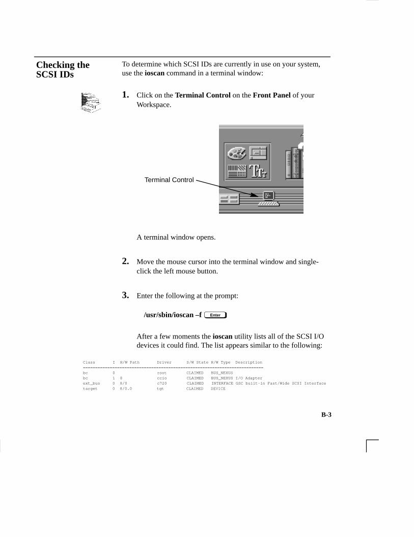
B-3
To determine which SCSI IDs are currently in use on your system,use the ioscan command in a terminal window:
1. Click on the Terminal Control on the Front Panel of yourWorkspace.
Terminal Control
A terminal window opens.
2. Move the mouse cursor into the terminal window and single-click the left mouse button.
3. Enter the following at the prompt:
/usr/sbin/ioscan –f Enter
After a few moments the ioscan utility lists all of the SCSI I/Odevices it could find. The list appears similar to the following:
Class I H/W Path Driver S/W State H/W Type Description==========================================================================bc 0 root CLAIMED BUS_NEXUS bc 1 8 ccio CLAIMED BUS_NEXUS I/O Adapterext_bus 0 8/0 c720 CLAIMED INTERFACE GSC built-in Fast/Wide SCSI Interfacetarget 0 8/0.0 tgt CLAIMED DEVICE
Checking theSCSI IDs

B-4
disk 3 8/0.0.0 sdisk CLAIMED DEVICE QUANTUM LPS1080WDtarget 1 8/0.5 tgt CLAIMED DEVICE disk 2 8/0.5.0 sdisk CLAIMED DEVICE DEC DSP3210SWtarget 2 8/0.6 tgt CLAIMED DEVICE disk 0 8/0.6.0 sdisk CLAIMED DEVICE DEC DSP3210SWba 0 8/12 bus_adapter CLAIMED BUS_NEXUS Core I/O Adapterext_bus 2 8/12/0 CentIf CLAIMED INTERFACE Built-in Parallel Interfaceaudio 0 8/12/1 audio CLAIMED INTERFACE Built-in Audiotty 0 8/12/4 asio0 CLAIMED INTERFACE Built-in RS-232Cext_bus 1 8/12/5 c700 CLAIMED INTERFACE Built-in SCSItarget 3 8/12/5.2 tgt CLAIMED DEVICE disk 1 8/12/5.2.0 sdisk CLAIMED DEVICE TOSHIBA CD-ROM XM-4101TAtarget 4 8/12/5.3 tgt CLAIMED DEVICE tape 0 8/12/5.3.0 stape CLAIMED DEVICE HP HP35480Atarget 5 8/12/5.4 tgt CLAIMED DEVICE disk 10 8/12/5.4.0 sdisk CLAIMED DEVICE SEAGATE ST3600Ntarget 6 8/12/5.6 tgt CLAIMED DEVICE disk 5 8/12/5.6.0 sdisk CLAIMED DEVICE MICROP 2112lan 0 8/12/6 lan2 CLAIMED INTERFACE Built-in LANps2 0 8/12/7 ps2 CLAIMED INTERFACE Built-in Keyboard/Mousebc 2 10 ccio CLAIMED BUS_NEXUS I/O Adaptergraphics 0 10/0 graph3 CLAIMED INTERFACE Graphicsgraphics 1 10/8 graph3 CLAIMED INTERFACE Graphicsext_bus 3 10/12 c720 CLAIMED INTERFACE GSC add-on Fast/Wide SCSI Interfacetarget 7 10/12.4 tgt CLAIMED DEVICE disk 6 10/12.4.0 sdisk CLAIMED DEVICE SEAGATE ST31200Wgraphics 2 10/16 graph3 CLAIMED INTERFACE Graphicsba 1 10/20 bus_adapter CLAIMED BUS_NEXUS Core I/O Adaptertty 1 10/20/2 asio0 CLAIMED INTERFACE Built-in RS-232Cba 2 10/20/5 eisa CLAIMED BUS_NEXUS EISA Bus Adapterext_bus 4 10/20/5/3 hshpib CLAIMED INTERFACE EISA card HWP0C70
target 8 10/20/5/3.0 tgt CLAIMED DEVICE
disk 7 10/20/5/3.0.0 cs80 CLAIMED DEVICE disk 07959
target 9 10/20/5/3.1 tgt CLAIMED DEVICE disk 8 10/20/5/3.1.0 cs80 CLAIMED DEVICE disk 07959target 10 10/20/5/3.2 tgt CLAIMED DEVICE disk 9 10/20/5/3.2.0 cs80 CLAIMED DEVICE disk 07959processor 0 32 processor CLAIMED PROCESSOR Processor
memory 0 49 memory CLAIMED MEMORY Memory

B-5
4. You can determine which SCSI IDs are currently in use by look-ing under the H/W Path heading. The listing 2.0.1 scsi is thebuilt-in SCSI bus controller. For devices connected to the built-in SCSI bus, such as disks, the fourth number is the SCSI ID forthat device. For example, the listing 2.0.1.6.0 in the sample de-vice list tells you that there is a SCSI device (a disk) currentlyusing ID 6 on the SCSI bus.
The information is presented in a different format if you are using HP-UX 10.0 or later; although you still look under the H/W Path heading.
NOTICE: Never use SCSI address 7 for any device. Ad-dress 7 is reserved for the SCSI controller.

B-6
Perform the following steps to open the system unit:
1. Power off the system, the monitor, and any peripheral devices.Unplug the system unit power cord and the power cord of anyperipheral devices from ac wall outlets. Refer to Using Your HPWorkstation for the proper method of shutting down your work-station.
2. Attach the static-grounding wrist strap by following the instruc-tions on the package. Attach the sticky end of the wrist strap tobare metal on the back panel of the system unit.
3. Press down on the two buttons on the top front of the worksta-tion, releasing the front panel (also known as the front bezel) asshown in Figure B–1.
Opening theSystem Unit

B-7
Figure B–1. Removing the Front Panel
4. Swing the panel down and pull up slightly so the two guide pinson the bottom clear their guides and lay the front cover down.
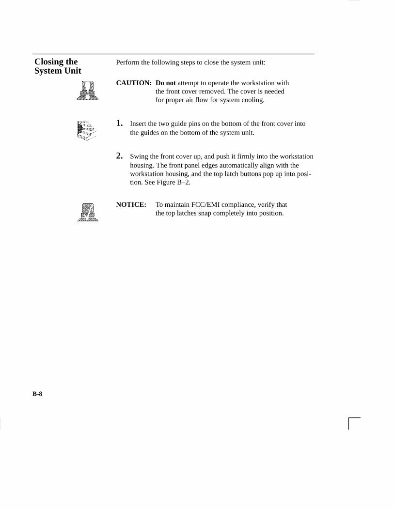
B-8
Perform the following steps to close the system unit:
CAUTION: Do not attempt to operate the workstation withthe front cover removed. The cover is neededfor proper air flow for system cooling.
1. Insert the two guide pins on the bottom of the front cover intothe guides on the bottom of the system unit.
2. Swing the front cover up, and push it firmly into the workstationhousing. The front panel edges automatically align with theworkstation housing, and the top latch buttons pop up into posi-tion. See Figure B–2.
NOTICE: To maintain FCC/EMI compliance, verify thatthe top latches snap completely into position.
Closing the System Unit

B-9
Figure B–2. Replacing the Front Panel
3. Reconnect the power cables and any other cables that you dis-connected when opening the workstation, then power on any pe-ripherals, the monitor, and the system unit.

B-10
Your workstation can have any two of the following removable mediadevices, with no two the same:
• CD-ROM drive
• 2 to 8 GB, 4 mm DDS tape drive
• 3.5-inch Floppy disk drive
Follow these steps for installing any of the removable media drivesinto the Storage Assembly. The steps for checking and setting drivejumpers are different for each drive. Jumper information for eachdrive is included in these steps.
NOTICE: Before opening the system unit, follow theinstructions in “Checking the SCSI IDs,” earlierin this appendix, to determine the SCSI IDscurrently in use on your workstation.
1. Open the system unit according to the directions in “Opening theSystem Unit,” earlier in this appendix.
2. Unscrew the two captive screws on the left side of the StorageAssembly and pull down the drawer ejector handle on the rightside of the Storage Assembly, as shown in Figure B–3.
The Storage Assembly slides partway out of the drawer.
InstallingRemovable Media Devices

B-11
���� �������� �����
����� �������� �������� ����� ����� ��� ������� ��� ��� ����� �����
������� ������� �����
Figure B–3. Removing Storage Drawer from System Unit
3. Pull the Storage Assembly out as far as it will go. (A safety catchprevents the drawer from coming all the way out.)
NOTICE: When sliding the Storage Assembly out of thesystem unit, move the drawer ejector handle toprevent the Storage Assembly from hitting it.
4. Push in on the safety catch and continue pulling the drawer out.Be sure to support the drawer from the bottom.
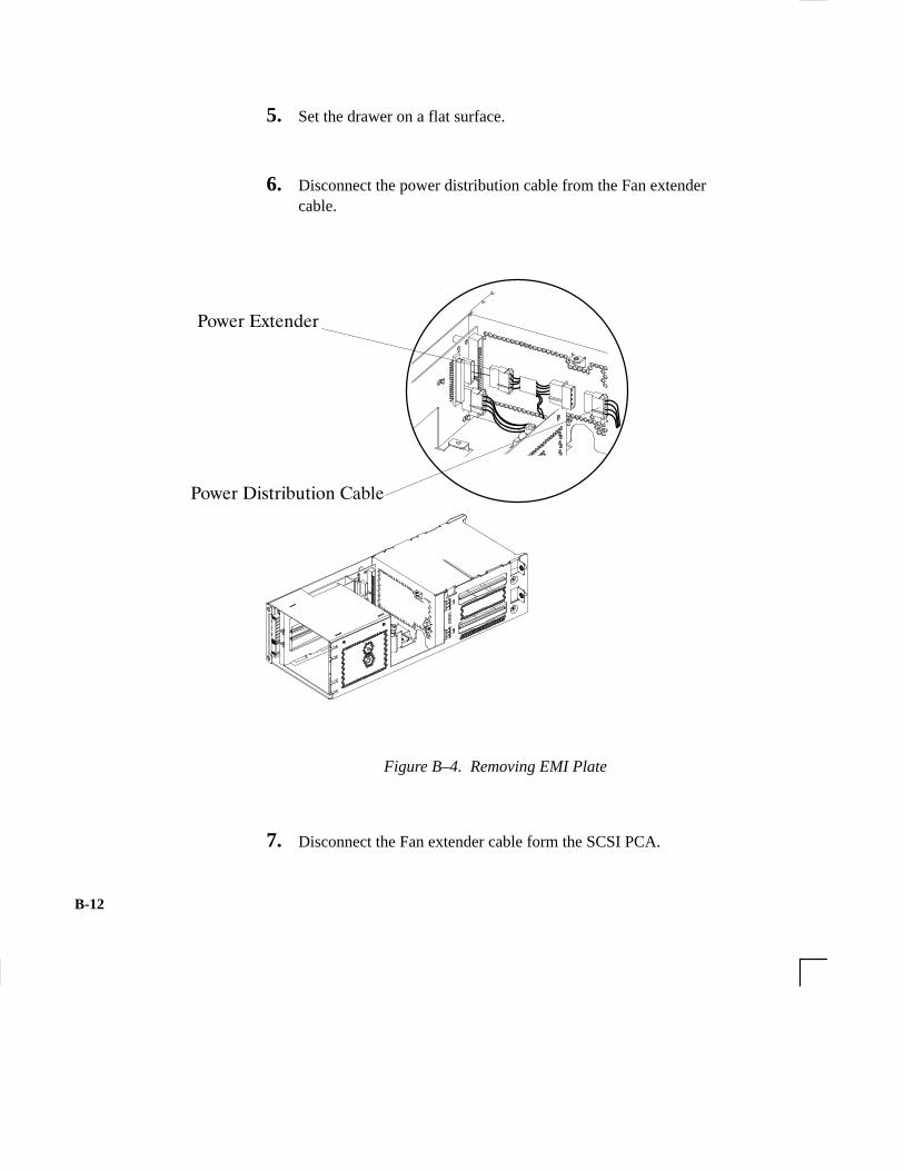
B-12
5. Set the drawer on a flat surface.
6. Disconnect the power distribution cable from the Fan extendercable.
� ��� ������
� ��� ������� �� ����
Figure B–4. Removing EMI Plate
7. Disconnect the Fan extender cable form the SCSI PCA.

B-13
Figure B–5. Removing FAN/EMI Plate
8. Unscrew the captive screw holding the FAN/EMI plate at theback of the removable drives and lift the plate up and out of thedrawer, as shown in Figure B–45
9. Disconnect the SCSI and power cables from the drive.

B-14
10. Unscrew the two screws holding the drive in the storage drawer,and slide the drive out of the drawer. See Figure B–6.
Figure B–6. Removing Drive Screws
11. Check the SCSI address/jumper settings on the replacementdrive, using the following information sections.
B-15
CD-ROM Drive
The CD-ROM drive ships with the drive set to SCSI ID address2. We recommend keeping the address setting at 2 unless it isused by another device.
CAUTION: CD-ROM drives are susceptible to mechanicaland electrostatic shock. When handling the drive,always wear the static-grounding wrist strap thatcame in the CD-ROM drive kit. Always handlethe drive carefully.
If you need to change the CD-ROM drive’s address, follow theseinstructions, referring to Figure B–7. If you do not need tochange the drive’s address, go to Step 10 of this installation pro-cedure.
1. Locate the jumpers at the back of the CD-ROM drive.
2. To change the address, use needlenose pliers to set thedrive’s SCSI ID to an address that is not used by anotherSCSI device. Check that the other jumpers are set correctly.
NOTICE: Do not use SCSI ID 7 for your CD-ROM drive’sSCSI address. The host SCSI controller usesSCSI ID 7.
3. Use needlenose pliers to remove the SCSI terminators, ifstill attached to the drive.

B-16
���������
ID 4ID 2ID 1
Jumpers
0
1
2
3
4
5
6
7
SCSI ID Address
ID 1ID 2ID 4
PRTY
PRV/ALMTESTTERM
Figure B–7. CD-ROM Drive SCSI Address/Jumper Settings

B-17
DDS Tape DriveThe DDS tape drive ships with the drive set to SCSI ID address3 and the Operation Mode switches set for correct drive opera-tion. We recommend keeping the address setting at 3 unless it isused by another device.
CAUTION: SCSI tape drives are susceptible to mechanicaland electrostatic shock. When handling the drive,always wear the static-grounding wrist strap thatcame in the DDS tape drive kit. Always handlethe drive carefully.
If you need to change the DDS tape drive’s address or operationmode, follow these instructions, referring to Figure B–8 for theDDS-DC drive, Figure B–9 for the DDS-2 drive, and FigureB–10 for operation mode. If you do not need to change thedrive’s address or operation mode, go to Step 10 of this installa-tion procedure.
1. Locate the jumpers at the back of the DDS tape drive.
2. To change the jumper settings, use needlenose pliers to setthe drive’s SCSI ID to an address that is not used by anotherSCSI device. Check that the other jumpers are set correctly.
NOTICE: Do not use SCSI ID 7 for your DDS tape drive’sSCSI address. The host SCSI controller usesSCSI ID 7.
3. Use needlenose pliers to remove the SCSI terminators, ifstill attached to the drive.
4. If you need to change the Operation Mode switches, locatethe switches on the underside of the DDS tape drive.Switches 1 and 2 are used to configure the data compressionoperation mode. Switches 3 through 8 are used to specifydrive connectivity and functionality according to host orcustomer requirements. The default setting is all switchesON. Figure B–10 shows the available options.

B-18
TargetID
Jumpers
0
1
2
3
Jumpers
4
5
6
TargetID
SCSI Terminators(must be removed)
(Default)
TermPWR ID2 ID1 ID0 ID2 ID1 ID0
TermPWR
Figure B–8. DDS-DC Tape Drive SCSI Address/Jumper Settings

B-19
SCSIID
0
1
2
3
4
5
6
SCSIID
(Default)
TermPWR* Bit 2 Bit 1 Bit 0 Bit 2 Bit 1 Bit 0
TermPWR*
SCSI Connector Power Connector
Bit 2Bit1
Bit 0
TermPWR
*Term PWR is not used in HP workstation configurations.
Figure B–9. DDS-2 Tape Drive and SCSI Address/Jumper Settings

B-20
��� �"���� �����#�"���!
��
� � � � � �
��
� � � � � �
���� �!!���� ��!��������� ��!"� ���" ��
���� �!!���� ���������� ��!"� ���" ��
���� �!!���� ��!������� ��!"���� ���" ��� ���� �!!���
���� �!!���� ���������"�� ��!"� ���" ��������� ������
��
� � � � � �
��
� � � � � �
Figure B–10. Switch Settings for Data Compression Operation Mode

B-21
Floppy Drive
The floppy disk drive ships with the drive set to SCSI ID address 0. We recommend keeping the address setting at 0 unless it is used by another device.
CAUTION: Floppy disk drives are susceptible to mechanicaland electrostatic shock. When handling the drive,always wear the static-grounding wrist strap thatcame in the floppy disk drive kit. Always handlethe drive carefully.
If you need to change the floppy disk drive’s address, followthese instructions, referring to Figures B–11 and B–12. If you donot need to change the drive’s address, go to Step 10 of thisinstallation procedure.
1. Locate the jumpers on the top of the floppy drive.
2. To change the jumpers, use needlenose pliers to set thedrive’s SCSI ID to an address that is not used by anotherSCSI device. Check that the other jumpers are set correctly.
NOTICE: Do not use SCSI ID 7 for your floppy drive’sSCSI address. The host SCSI controller usesSCSI ID 7.
3. Use needlenose pliers to remove the SCSI terminators, ifstill attached to the drive.
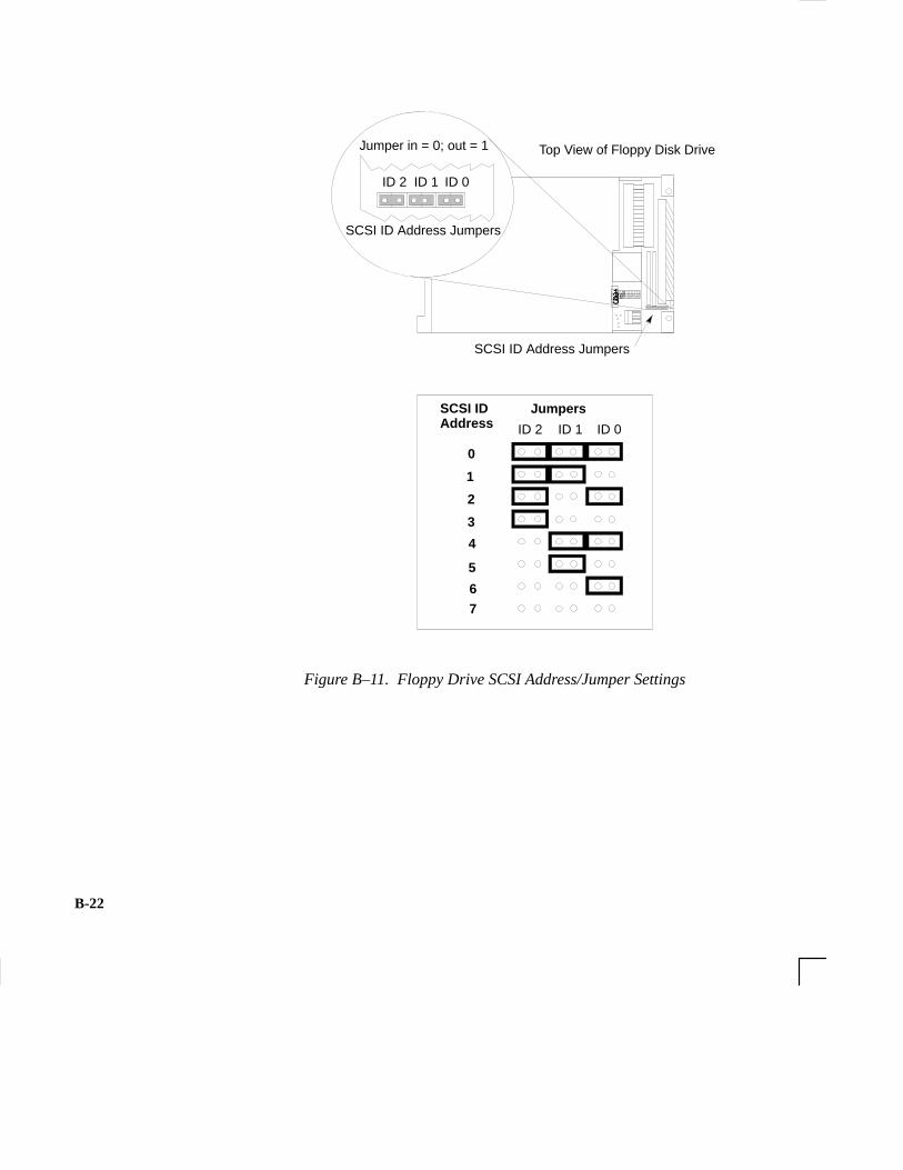
B-22
SCSI ID Address Jumpers
ÅÅ
Å
Top View of Floppy Disk Drive
��
ID 0ID 1ID 2
Jumper in = 0; out = 1
SCSI ID Address Jumpers
ID 0ID 1ID 2
Jumpers
0
1
2
3
4
5
6
7
SCSI ID Address
�
Figure B–11. Floppy Drive SCSI Address/Jumper Settings

B-23
ÅÅÅÅ
ÅÅÅÅ
Top View of Floppy Disk Drive
123
SCSI Terminators
Figure B–12. Floppy Drive Terminators
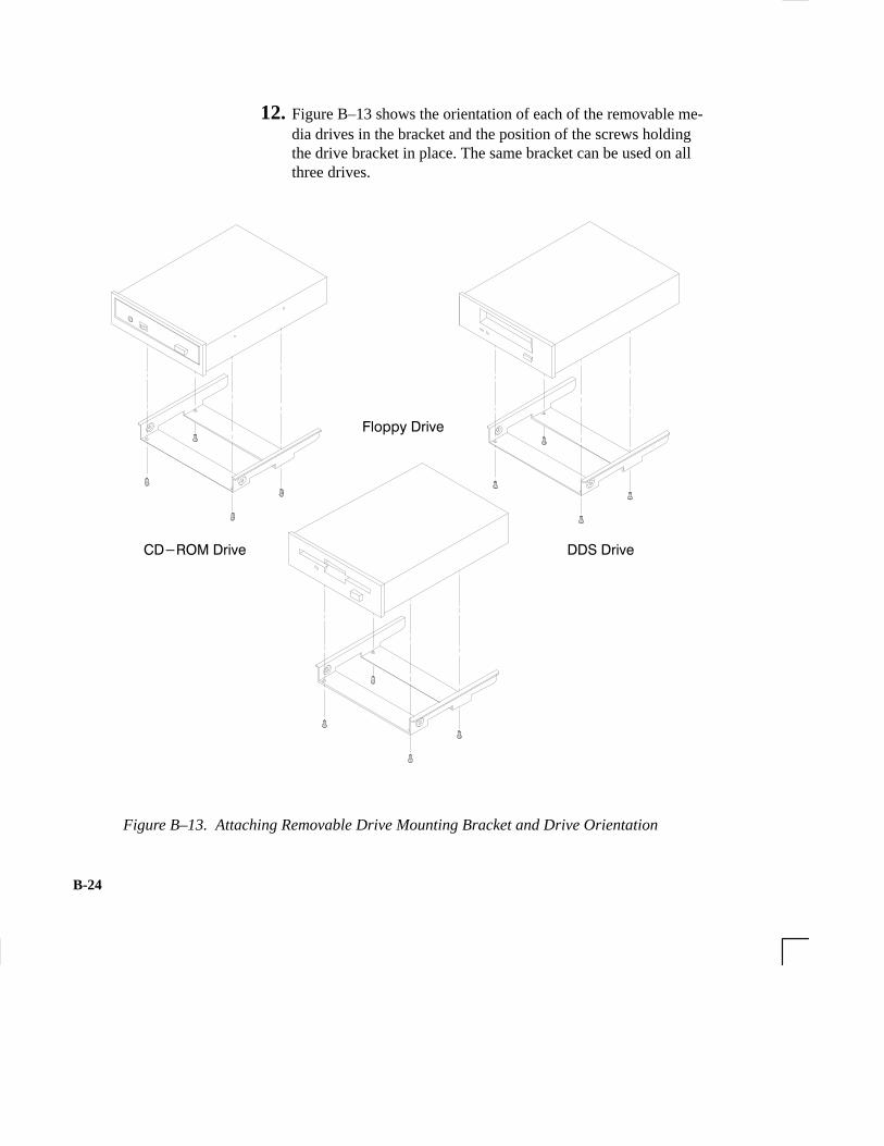
B-24
12. Figure B–13 shows the orientation of each of the removable me-dia drives in the bracket and the position of the screws holdingthe drive bracket in place. The same bracket can be used on allthree drives.
�����������
�� ��������
�������
Figure B–13. Attaching Removable Drive Mounting Bracket and Drive Orientation

B-25
13. With the disk mounting bracket between the guides on each sideof the Storage Assembly, slide the disk into the Storage Assem-bly, securing it with the two side screws. See Figure B–14. Donot over-tighten the side screws.
Reconnect the driveSCSI and power cableshere.
Figure B–14. Replacing Drive Screws
14. Reconnect the cabling from the back of the drive to the side ofthe drawer assembly. See Figure B–14.
15. Secure the EMI plate at the back of the removable drives withthe captive screw in the bottom of the plate.
16. Slide the drawer back in.

B-26
17. Push the drawer ejector handle up until the Storage Assemblyslides all the way into the system unit and secure the two captivescrews on the left of the Storage Assembly, as shown in Figure B–15.
NOTICE: If the ejector handle is not pushed completelyin, you may not have proper seating of the SCSIPCB interconnect to the backplane.
���� �������� �����
����� �������� �������� ����� ����� ��� ������� ��� ��� ����� �����
������� ������� �����
Figure B–15. Replacing the Storage Drawer Assembly
B-27
18. Follow the instructions in “Checking the SCSI IDs” earlier inthis appendix, to verify that your workstation can see the newlyinstalled drive.
For information about using your drives see the following chapters inthis book:
• Using your CD-ROM drive is in Chapter 3.
• Using your DDS tape drive is in Chapter 4.
• Using your floppy drive is in Chapter 5.
B-28
This section describes how to add a hard drive to your workstation.The first part deals with installing a hard drive and the second parttells you how to configure your hard disk after it is installed.
Your workstation can have two hard drives. The hard drive that camewith your workstation was set to SCSI ID 6. If you are adding a se-cond hard disk, the second hard disk will use SCSI ID 5. If anotherdevice on your workstation is using SCSI ID 5, change the hard disk’sSCSI ID to an unused SCSI ID.
NOTICE: Do not use SCSI ID 7 for your hard drive’sSCSI address. The host SCSI controller usesSCSI ID 7. If you are adding a second harddrive, we advise you not to use SCSI ID 6which is normally reserved for the boot diskdrive.
Check the jumpers on the hard drive you plan to install. Figure B–16shows the correct SCSI address for the jumpers on your drive. Thesejumpers are the only jumpers you may need to change on the drive.
1. Use a pair of small needle-nose pliers to set the SCSI IDjumpers to SCSI ID 5 if you are adding a second hard drive,or SCSI ID 6 if this is the first hard drive (you are runningdiskless). Check that the other jumpers are set correctly.
2. If you removed the disk drive mounting bracket from thedisk drive, replace it now, making sure not to over-tightenthe screws. Figure B–17 shows the orientation of the drivein the bracket for both drives and the position of the screwsholding the drive bracket in place.
Be sure the printed circuit side of one drive is facing theprinted circuit side of the other drive.
Adding a Hard Drive

B-29
�������� ��� ����� � ����
6
5
4
3
2
1
0
15
14
13
12
11
10
98
��������������
������������
Figure B–16. Fast, Wide Hard Drive Jumper Settings

B-30
PCB Side of Drive
Top Drive
Bottom Drive
Figure B–17. Replacing Hard Drive Mounting Bracket and Drive Orientation

B-31
Installing a Hard Disk Drive
Perform the following steps to install a hard disk drive.
NOTICE: Before opening the system unit, follow theinstructions in “Checking the SCSI IDs,” earlierin this appendix, to determine the SCSI IDscurrently in use on your workstation.
1. Open the system unit according to the directions in “Opening theSystem Unit,” earlier in this appendix.
2. Unscrew the two captive screws on the left side of the StorageAssembly and pull down the drawer ejector handle on the rightside of the Storage Assembly, as shown in Figure B–18.
The Storage Assembly slides partway out of the drawer.

B-32
���� �������� �����
����� �������� �������� ����� ����� ��� ������� ��� ��� ����� �����
������� ������� �����
Figure B–18. Removing Storage Drawer from System Unit
3. Pull the Storage Assembly out as far as it will go. (A safety catchprevents the drawer from coming all the way out.)
NOTICE: When sliding the Storage Assembly out of thesystem unit, move the drawer ejector handle toprevent the Storage Assembly from hitting it.
4. Press in on the safety catch on each side of the drawer to allowthe drawer all the way out and place the drawer on a flat surface.

B-33
5. Be sure you have already checked the SCSI ID of the drive youwant to install using the method described at the beginning ofthis section.
6. With the disk mounting bracket between the guides on each sideof the Storage Assembly, slide the disk into the Storage Assem-bly, securing it to the drawer with two side screws. See Figure B–19. Do not over-tighten the side screws.
The drives should be placed in the drive bays with the bottom ofeach drive toward the middle, as shown in Figure B–19. Refer toFigure B-16 for drive orientation in the bracket.
Figure B–19. Placing Hard Drives in Storage Drawer

B-34
7. Reconnect the SCSI and power cables from the back of the driveto the side of the drawer assembly.
8. Slide the drawer back in and secure.
9. Close the system unit and reconnect all cables as described in the“Closing the System Unit” section in this appendix.
10. Follow the instructions in the “Checking the SCSI IDs” subsec-tion to verify that your workstation can see the hard drive.
Configuring a Hard Drive
This section describes how to add a hard disk drive to your system asa file system using SAM. For more information about configuring ahard disk drive, refer to the System Administration Tasks manual.
The procedures in this chapter require you to log in as root. If youcannot log in as root, contact your system administrator.
1. Log in as root.
2. Move the mouse pointer to the up arrow above the Toolboxcontrol and click the left mouse button.
Toolbox ControlUp Arrow

B-35
3. The Toolbox subpanel opens. Click on the General toolboxicon, shown below.
4. A file manager window appears with a number of icons in it.Double-click on the System_Admin toolbox icon.
5. Move the mouse cursor to the SAM icon shown below (youricon can look like either of these) and double-click the leftmouse button.
6. The System Administration Manager window opens. Double-click on Peripheral Devices –>.
7. The Peripheral Devices window opens. Double–click on Disksand File Systems –>.
8. The Disks and File Systems window opens. Double-click onCD-ROM, Floppy, and Hard Disks.
SAM (System Adminis-tration Manager) is a util-ity that performs systemadministration tasks us-ing a windows graphicaluser interface.

B-36
The following screen message appears:
Scanning the system’s hardware...
The CD-ROM, Floppy, and Hard Disks window opens con-taining a list of drives currently configured on this system.
9. From the Actions menu, click on Add a Hard Disk Drive.
10. The Select a Disk to Add... window opens with a list of unuseddisks. Highlight the hard disk drive you want to add to your sys-tem.
11. Click on O K .
12. The Set Disk Usage and Options... window opens. Select FileSystem and click on O K .
13. The following screen messages appear:
Task started.
Creating the device file...Modifying “/etc/checklist”...Task completed.
Click on O K .

B-37
Take a moment to read over the following important notes aboutinstalling memory:
• Before trying to install additional memory DIMMs in your J 280 workstation, use the procedure described in Appendix D, “The Boot Console Interface,” to determine the current memory configuration for this workstation.
• Read over the steps involved in installing memory DIMMs before you begin.
• DIMMs must be inserted in the order shown. Refer to Figure B–21.
• You must insert DIMMs in pairs of equal size.
• Be aware that it is possible to insert the DIMMs backwards intothe connectors. Be sure therefore, that you understand the prop-er orientation for DIMMs going into the connectors. See Figure B–22.
• When you have finished installing additional DIMMs, use theBoot Console Interface to verify that they are seen by the work-station.
Perform the following steps to add memory DIMMs to your worksta-tion. Note the instructions in Step 8 of this section on DIMM configu-ration before beginning these steps.
1. Open the system unit according to the directions in the “Openingthe System Unit” section earlier in this appendix.
2. Remove the two screws in the center of the CPU Assembly.
3. Release the ejector tabs on the left side, top and bottom of theCPU Assembly. Refer to Figure B–20.
Installing AdditionalMemory

B-38
Ejector Tab
Ejector Tab
Figure B–20. Removing the CPU Assembly
4. Pull the CPU Assembly straight out and place on a flat surfacewith an antistatic mat.
NOTICE: The CPU Assembly is heavy and has no safetycatch. Be sure to pull it out slowly, making sureit is properly supported.
5. Use Figure B–21 to locate the memory DIMMs on the CPU As-sembly.

B-39
Memory DIMMs
Figure B–21. Memory DIMM Location
6. To install a new memory DIMM, turn the CPU assembly untilthe memory DIMMs are in the position shown in Figure B–22.

B-40
��� �� �����
������� ����
Figure B–22. CPU Assembly Orientation
7. Refer to the Position Guide on the CPU board that states,“<–– POSITION MEM MODULE AS SHOWN,” as shown inFigure B–22.
8. Install pairs of DIMMs in the following order: Pair 1 (0A, 0B),Pair 2 (1A, 1B), Pair 3 (2A, 2B), and so on.
This workstation has 16 memory slots, labeled 0A, 0B through7A, 7B. Memory can be configured from 32 MB to 256 MBinstalled in pairs of 16 MB DIMMs. Memory can be configuredfrom 128 MB to 1 GB, installed in pairs of 64 MB DIMMs, ormemory can be configured from 32 MB to 1 GB in combinationsof pairs of 32 MB and 128 MB DIMM pairs. Memory DIMMsmust be installed in pairs of equal size, with 128 MB DIMMpairs installed first, followed by 32 MB DIMM pairs. FigureB–23 gives the recommended order for installing pairs ofDIMMs.

B-41
Any Combination of memory may be used, although, for maxi-mum performance, we recommend using common-sized memoryDIMMs; either all 32 MB or 128 MB DIMM pairs. Therefore, toachieve both maximum performance and maximum future ca-pacity, use 128 MB DIMM pairs exclusively.
���� ����"� ��
�
��
�
�
�
��
��
�
�
��
��
�
�
��
��
������
������
������
������
�����
������
�����
������
�������!���
��
��
���
���
���
���
���
��
���
���
���
���
���
���
���
���
Figure B–23. Memory DIMM Sequence
9. Open the ejector tab by pressing down on it at the left of the con-nector. Refer to Figure B–24.

B-42
10. Place the DIMM in the connector, lining it up with the guides.Make sure to put the notched end toward the ejector handle (tothe left).
����� ��������������������������������� �����
���������� �����������
������������������ �� ������
�������������������� ��������������������������������� �����
������ ���
������������������������������������������������������� ����������������������������������������
����������������������
������������������������������������������ ����� �
��������
����������������������
Figure B–24. Installing Memory Cards
11. Close the ejector tab.
12. Press firmly and evenly on the DIMM to ensure that it seatsproperly.
13. To replace the CPU Assembly in the system unit, first align thetop of the CPU Assembly with the guide on the system unit. Re-fer to Figure B–25 and to the label on the back of the assembly.Be sure to support the CPU Assembly properly while replacingit.
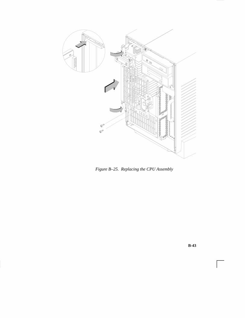
B-43
Figure B–25. Replacing the CPU Assembly
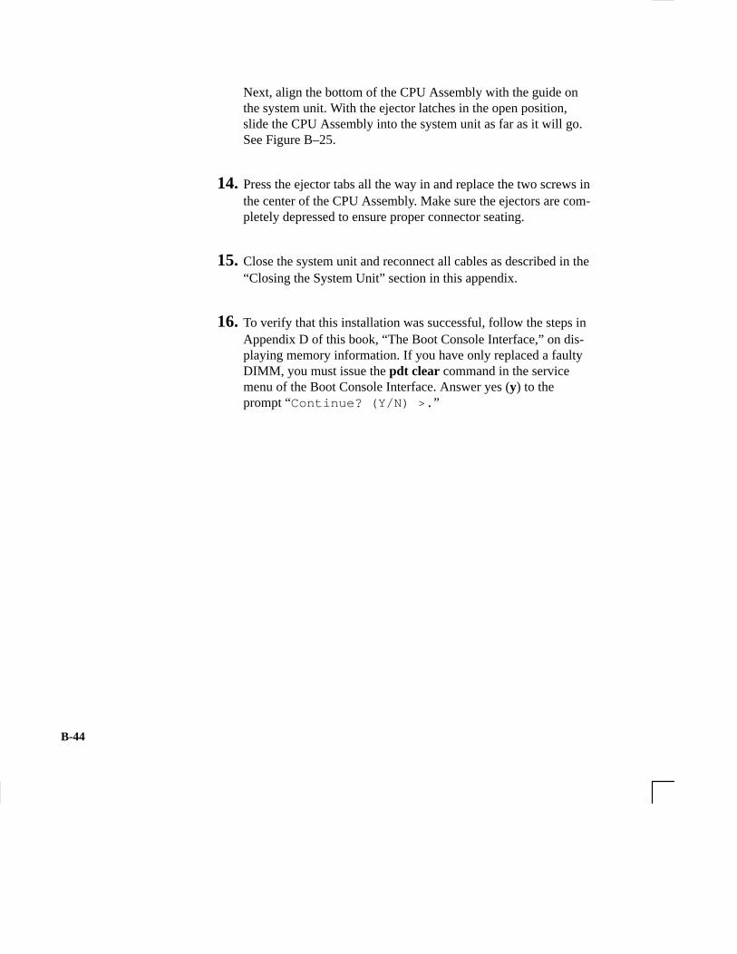
B-44
Next, align the bottom of the CPU Assembly with the guide onthe system unit. With the ejector latches in the open position,slide the CPU Assembly into the system unit as far as it will go.See Figure B–25.
14. Press the ejector tabs all the way in and replace the two screws inthe center of the CPU Assembly. Make sure the ejectors are com-pletely depressed to ensure proper connector seating.
15. Close the system unit and reconnect all cables as described in the“Closing the System Unit” section in this appendix.
16. To verify that this installation was successful, follow the steps inAppendix D of this book, “The Boot Console Interface,” on dis-playing memory information. If you have only replaced a faultyDIMM, you must issue the pdt clear command in the servicemenu of the Boot Console Interface. Answer yes (y) to theprompt “Continue? (Y/N) >. ”
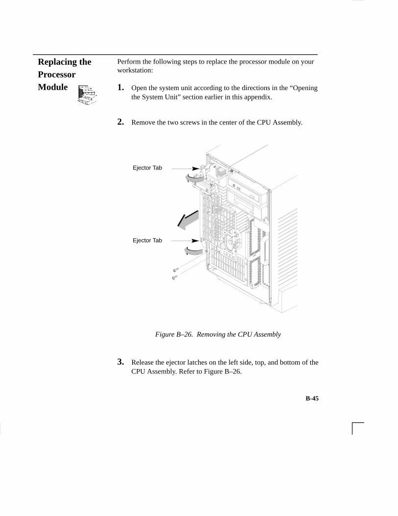
B-45
Perform the following steps to replace the processor module on yourworkstation:
1. Open the system unit according to the directions in the “Openingthe System Unit” section earlier in this appendix.
2. Remove the two screws in the center of the CPU Assembly.
Ejector Tab
Ejector Tab
Figure B–26. Removing the CPU Assembly
3. Release the ejector latches on the left side, top, and bottom of theCPU Assembly. Refer to Figure B–26.
Replacing theProcessorModule
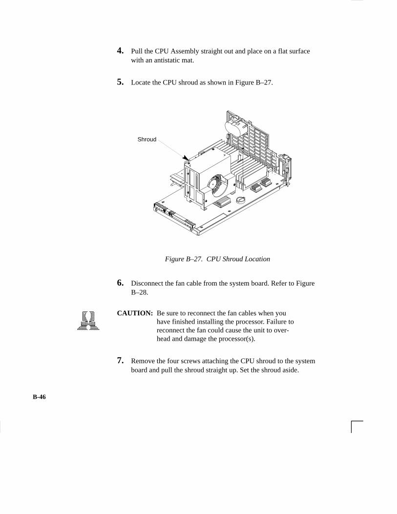
B-46
4. Pull the CPU Assembly straight out and place on a flat surfacewith an antistatic mat.
5. Locate the CPU shroud as shown in Figure B–27.
Shroud
Figure B–27. CPU Shroud Location
6. Disconnect the fan cable from the system board. Refer to FigureB–28.
CAUTION: Be sure to reconnect the fan cables when youhave finished installing the processor. Failure toreconnect the fan could cause the unit to over-head and damage the processor(s).
7. Remove the four screws attaching the CPU shroud to the systemboard and pull the shroud straight up. Set the shroud aside.

B-47
���� ���� ���������
� ��� � ������� ��� ��� ����������� ����������
������� ������ �� � ��������� �� ����
Figure B–28. Removing CPU Shroud and Disconnecting Fan Cable
8. When replacing a processor module, you must also remove onedust cover because:

B-48
• Processors are shipped with a dust cover (A) over the connector.
To remove these dust cover, follow the steps in Figure B–29.
��� ����� � � ���� ����� ��� � � ���������� ������ ������ � � ����� ������� � � ����� �����
�������� � � ��������� ����� ����� � ��������� ��� ������� ��� ��� ���� � ��������� ��� �������� ��������� �����
��
��
Figure B–29. Removing CPU Dust Cover

B-49
9. Insert the board containing the processor module into the guidesand press firmly into place.
10. Reconnect the fan cable to the system board.
11. Replace the CPU shroud over the processor and replace the fourscrews attaching the CPU shroud to the system board
12. To replace the CPU Assembly in the system unit, first align thetop of the CPU Assembly with the guide on the system unit. Re-fer to Figure B–30 and to the label on the back of the assembly.Be sure to support the CPU Assembly properly while replacingit.
Figure B–30. Replacing the CPU Assembly

B-50
Next, align the bottom of the CPU Assembly with the guide onthe system unit. With the ejector latches in the open position,slide the CPU Assembly into the system unit as far as it will go.See Figure B–30.
13. Press the ejector tabs all the way in and replace the two screws inthe center of the CPU Assembly. Make sure the ejectors are com-pletely depressed to ensure proper connector seating.
14. Close the system unit and reconnect all cables as described in the“Closing the System Unit” section in this appendix.
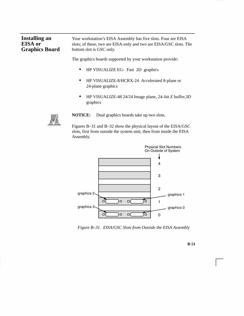
B-51
Your workstation’s EISA Assembly has five slots. Four are EISAslots; of these, two are EISA-only and two are EISA/GSC slots. Thebottom slot is GSC only.
The graphics boards supported by your workstation provide:
• HP VISUALIZE EG- Fast 2D graphics
• HP VISUALIZE-8/HCRX-24 Accelerated 8-plane or24-plane graphics
• HP VISUALIZE-48 24/24 Image plane, 24–bit Z buffer,3Dgraphics
NOTICE: Dual graphics boards take up two slots.
Figures B–31 and B–32 show the physical layout of the EISA/GSCslots, first from outside the system unit, then from inside the EISAAssembly.
�
�
�
�
�
������ ���
������ ���
������ ���
������ ���
���� ���������������������������������
Figure B–31. EISA/GSC Slots from Outside the EISA Assembly
Installing an EISA or Graphics Board

B-52
������
������
������
������
������
������
������
�������� ���������
��������������������
����� ��������������
Figure B–32. EISA/GSC Slots from Inside the EISA Assembly
Physical slot 0 is always reserved for graphics cards only.
graphics0 Graphics device in slot 0. If using a Dual Graphics Card,this is the port to the right on the card when facing the back of theworkstation.
graphics1 Graphics device in slot 1. If using a Dual Graphics Card,this is the port to the right on the card when facing the back of theworkstation.
graphics2 Graphics device in slot 2. If there is a Dual GraphicsCard in slot 1, this is the port to the left on the card when facing theback of the workstation.
graphics3 This is a logical slot, and can only be reached by usingthe left port of a Dual Graphics Card in physical slot 0.

B-53
Follow these steps to install an EISA or graphics board into yourworkstation:
1. Working from the rear of the workstation, unscrew the four cap-tive screws and pull the EISA Assembly straight out using thehandle. See Figure B–33.
Figure B–33. Removing the EISA Assembly

B-54
2. Rotate the unit 90 degrees clockwise and place on a flat surface,as shown in Figure B–34.
Figure B–34. Rotating the EISA Assembly for Installation

B-55
3. Unscrew one screw at the back of the cover and lift the cover upand out to remove it from the EISA Assembly. See Figure B–35.
Figure B–35. Removing the EISA Assembly Cover

B-56
4. Unscrew one screw at the top of the slot cover and pull the coverstraight up to remove it. See Figure B–36.
Figure B–36. Removing the EISA Slot Cover

B-57
5. Place EISA or graphics board you are installing in the boardguides and slide firmly into the connector. Check to see theboard is evenly inserted to seat properly. See Figure B–37.
Figure B–37. Installing an EISA or Graphics Board in the EISAAssembly
6. Secure board with one screw in top of board connector bracket.

B-58
7. Insert cover in guide and secure with screw. Refer to Figure B–38.
�����
Figure B–38. Replacing EISA Assembly Cover
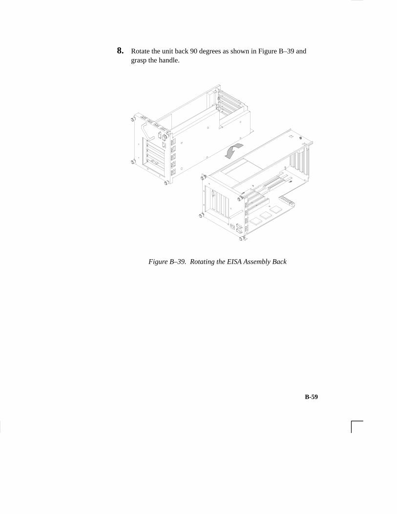
B-59
8. Rotate the unit back 90 degrees as shown in Figure B–39 andgrasp the handle.
Figure B–39. Rotating the EISA Assembly Back

B-60
9. Slide the EISA Assembly into the system unit and secure it withthe four captive screws. See Figure B–40.
Figure B–40. Replacing EISA Assembly

B-61
Your system ships from the factory preset to use a monitor with a spe-cific resolution and frequency. If you replace your monitor with a dif-ferent type, you must reconfigure your workstation to support it
There are two ways to configure your workstation to support a differ-ent monitor type:
Setting the Monitor Type from the Boot Console Interface
To change your workstation’s graphics parameters before you replaceyour monitor, go to “Displaying and Setting the Monitor Type” inAppendix D.
Setting the Monitor Type at Power On
If you
• replace your workstation’s monitor with a different monitortype, and
• do not set the workstation’s graphics parameters by using themonitor command before doing so,
then press Tab after your keyboard’s lights flash during the bootprocess to initiate the automatic monitor selection process.
Your system queries you for the new monitor type. Select the newtype by pressing Enter . The system queries you to confirm yourselection. Press y to save this monitor type.
If you don’t press y, the system cycles through the other monitortypes, some of which your monitor won’t display. Wait for theworkstation to display your monitor type again, then select it.
Changing YourMonitor Type

B-62
C-1
Appendix C
SCSI Connections
• SCSI bus differences
• SCSI restrictions
• Determining SCSI bus length
• Assigning SCSI device IDs
• Connecting to the SCSI ports

C-2
This appendix provides information about connecting Small Comput-er System Interface (SCSI) devices to an HP 9000 J 280 workstation.
The instructions in this chapter assume you are using the HP-UX version 10.20 or later operating system with the HP VUE version 3.0interface.
NOTICE: When attaching external SCSI devices, be sureto terminate the last device on the externalSCSI bus. If no external devices are attached,the SCSI connector on the rear of the systemmust be terminated with the terminator that wasshipped with your workstation.

C-3
A Small Computer Systems Interface (SCSI) bus is an IEEE standardbus for connecting your workstation to internal and external devices(SCSI devices) running at different speeds, singly or in combination.Examples of these SCSI devices are floppy disk drives, 4-mm DDS-format tape drives, CD-ROM drives, and Winchester hard disk drives.
There are two types of SCSI buses available with this workstation – asingle-ended SCSI bus, and a fast, wide SCSI bus. Table C–1 showsthe specification differences between these SCSI buses, and TableC–2 shows the SCSI addresses, ID numbers, and arbitration prioritiesfor each.
CAUTION: Do not mix single-ended and fast, wide deviceson any one bus type. Doing this will cause asystem failure.
Table C–1. SCSI Bus Differences
TransferRate
Data BusWidth
MaximumAddresses*
MaximumCable
Length
DevicePhysicalLocation
ControllerEmbedded or
Plugable
Single-Ended
up to 8 bits 8 6.0 meters internal and embeddedup to5 Mbytesper second
8 bits 8 6.0 meters(19.6 feet)
internal andexternal
embedded
Fast, Wide
up to 16 bits 16 25 meters internal and embeddedup to20 Mbytesper second
16 bits 16 25 meters(82 feet)
internal andexternal
embedded
* Address 7 is reserved for host controller use on both buses.
SCSI Bus Differences

C-4
Table C–2. SCSI Bus Addresses, ID Numbers, and Arbitration Priorities
SCSI–2Address Priority
SCSI–2 ID Number
7 . . . . . . . . 1 . . . . . . . 1
6 . . . . . . . . . 1 . . . . . . 2
5 . . . . . . . . . . 1 . . . . . 3
4 . . . . . . . . . . . 1 . . . . 4
3 . . . . . . . . . . . . 1 . . . 5
2 . . . . . . . . . . . . . 1 . . 6
1 . . . . . . . . . . . . . . 1 . 7
0 . . . . . . . . . . . . . . . 1 8
15 1 . . . . . . . . . . . . . . . 9
14 . 1 . . . . . . . . . . . . . . 10
13 . . 1 . . . . . . . . . . . . . 11
12 . . . 1 . . . . . . . . . . . . 12
11 . . . . 1 . . . . . . . . . . . 13
10 . . . . . 1 . . . . . . . . . . 14
9 . . . . . . 1 . . . . . . . . . 15
8 . . . . . . . 1 . . . . . . . . 16
8–bit devices
SCSI–2Single–Ended
16–bit
SCSI–3Fast, WideBus
devices
15 . . . . . . 8 7 . . . . . . 0
C-5
This section describes the SCSI restrictions that apply to your work-station in the following areas:
• Cables
• Connectors and terminator
• SCSI configuration constraints
Cables
All SCSI devices ship without cables. Only SCSI cables approved byHP can be used to connect your workstation and any SCSI devices.HP offers the following SCSI cables for single-ended standard SCSIdevices:
• K2296 cable with 0.9 meter (3 feet) length
• K2297 cable with 1.5 meter (5 feet) length
HP offers the following SCSI cables for connecting externally con-nected devices to the system fast, wide port:
• C2911A cable with 0.9 meter (3 feet) length
• C2924A cable with 2.5 meter (8.2 feet) length
• C2925A cable with 10.0 meter (32.8 feet) length
• C2926A cable with 20.0 meter (65.6 feet) length
CAUTION: SCSI cables approved by HP are designed tofunction within the SCSI tolerances for HP de-vices. Use of other cables can result in signifi-cant problems with system operation.
SCSIRestrictions

C-6
Singled-ended SCSI-2 definition limits the total cable length ofSCSI-2 cables to 6 meters (19.6 feet).
Fast, wide SCSI-3 definition limits the total cable length of SCSI-3cables to 25 meters (82 feet).
Always use the shortest possible cable(s) for your configuration.
If you are daisy-chaining single-ended standard SCSI-2 devices to-gether, use the following cables:
• 92222A cable with 0.5 meter (1.6 feet) length
• 92222B cable with 1.0 meter (3.2 feet) length
• 92222C cable with 2.0 meter (6.6 feet) length
If you are daisy-chaining fast, wide SCSI-3 devices together, use thefollowing cable:
• C2911A cable with 0.9 meter (3 feet) length
• C2924A cable with 2.5 meter (8.2 feet) length
• C2925A cable with 10.0 meter (32.8 feet) length
• C2926A cable with 20.0 meter (65.6 feet) length
NOTICE: See “Determining SCSI Bus Length” later inthis Appendix to determine the total length ofyour cables.
C-7
Connectors and Terminator
Any single-ended standard SCSI-2 device connecting to the systemboard must use a 50-pin high-density thumb screw connector on theend connecting to the system board, and a 50-pin low-density baillock connector on the other end. If you attach a second SCSI-2 de-vice, the cable must have low-density connectors on each end.
Any fast, wide SCSI-3 device connecting to the system board mustuse a 68-pin high-density thumb screw connector on both ends.
The last device connected to the SCSI bus must be terminated with aSCSI terminator. All of the devices listed ship without terminators. Ifyou do not already have a SCSI terminator, you must order terminatorK2291 (for 50-pin connectors) or C2905A (for 68-pin connectors)from Hewlett-Packard.
SCSI Configuration Constraints
You are limited to the number of same-type SCSI devices per system.Before adding another SCSI device, determine if the system can sup-port the additional device.
This workstation offers the following types of SCSI bus, each with itsown configuration constraints:
• single-ended standard SCSI-2 bus
• fast-wide, SCSI-3 bus
Single-Ended SCSI-2 Bus Configuration Constraints
For the single-ended standard SCSI-2 bus, HP-UX supports only oneof each type of removable disk drive and two of the same type tapedevices per system. Table C–3 shows configuration constraints foreach single-ended standard SCSI-2 device type. If the system has in-ternal hard disk drives or a floppy disk drive, you must count them asSCSI-2 devices.

C-8
Table C–3. Single-Ended SCSI-2 Bus Configuration Constraints
Single-Ended SCSI-2 DevicesMaximum Number of Each
Type of Device Allowed
Hard Disk Drives (internal and external)
Floppy Disk Drives
CD-ROM Drives
4-mm DDS Tape Drives (one internal)
9-track Tape Drives
650-MB Magneto-Optical Drives
Magneto-Optical Autochangers (see notice below)
Maximum Number of SCSI-2 Devices
7
1
1
2
2
1
1
7
NOTICE: Magneto-Optical Autochangers use three SCSI-2 drive addresses. Each address must be accounted for in the maximum number of SCSI-2 devices allowed.
CAUTION: Do not mix single-ended standard and fast,wide SCSI-2 peripherals.

C-9
Fast, Wide SCSI-3 Bus Configuration Constraints
Fast, wide SCSI-3 does not work with the single-ended standardSCSI-2. Table C–4 shows the configuration constraints for each fast,wide SCSI-3 device type.
Table C–4. Fast, Wide SCSI-3 Bus Configuration Constraints
External Fast, Wide SCSI-3 Devices
SCSI-3 Drive (fast, wide disk drives only) 15
SCSI-3 Disk Arrays (addressed as single drive) 7
Maximum Number of EachType of Device Allowed
CAUTION: Do not mix single-ended and fast, wide SCSIperipherals together on the same bus.
This section helps you to determine the total length of the single-en-ded standard SCSI-2 bus and the fast, wide SCSI-3 bus.
Single-Ended SCSI-2 Bus Length
Follow these instructions to calculate your total single-ended standardSCSI-2 bus length (including the system unit, external SCSI-2 de-vices, and SCSI-2 interconnect cables) using Table C–5:
1. Find all of your external SCSI-2 devices in the first column. Inthe third column, write the SCSI-2 bus lengths (from the secondcolumn) that correspond to your devices.
NOTICE: In the third column, the length for the SystemUnit is already listed. This number must alwaysbe used for the system unit.
DeterminingSCSI BusLength

C-10
2. In the fourth column, write down the lengths of the SCSI-2 interconnect cables you are using for your installation. (Cablelengths are listed in subsection “Cables” in the section on “SCSIRestrictions.”)
3. Add up all of the numbers in the third column and write thatnumber on the subtotal line at the bottom of the column. Do thesame for the fourth column.
4. Add the subtotals together and write the total in the Total SCSI-2Bus Length box.
NOTICE: The total length of the single-ended standardSCSI-2 bus must not exceed 6 meters (19.6feet). If the number you write for Total SCSI-2Bus Length is greater than 6 meters (19.6 feet),try configuring your installation with shortercables.
If you have problems, call your designated service representative.

C-11
Table C–5. SCSI-2 Bus Length Worksheet for Single-Ended Standard SCSI-2 Bus
Total SCSI-2 Bus Length =
SCSI-2 Device Cable Lengthmeters (feet) meters (feet)
System Unit
7980S
A1999A 0.3 (1.0)
C1701C
C1704C
Internal SCSI-2 Bus Length
+
Device Internal Length
Subtotals:
meters (feet)
External
C1520A
C1521A
C1700C
C1705C
C2213A
0.0 (0.0)
0.3 (1.0)
(Total SCSI-2 bus length not to exceed total of 6 meters [19.6 feet])
C2217T
1.5 (4.9) 1.5 (4.9) N/A
0.2 (0.7)
0.2 (0.7)
1.1 (3.6)
0.0 (0.0)
0.0 (0.0)
1.5 (4.9)
1.3 (4.3)
C-12
Fast, Wide SCSI-3 Bus Length
Follow these instructions to calculate your total fast, wide SCSI-3 buslength for the fast, wide SCSI-3 bus on your system using Table C–6:
1. List all of your internal SCSI-3 devices in the first column.
2. In the second column, write the lengths of the internal SCSI-3bus that correspond to your devices.
3. In the third column, write down the lengths of the SCSI-3 inter-connect cables you are using for your installation. (Cable lengthsare listed in subsection “Cables” in the “SCSI Restrictions” sec-tion.)
4. Add up all of the numbers in the second column and write thatnumber on the subtotal line at the bottom of the column. Do thesame for the third column.
5. Add the subtotals together and write the total in the Total SCSI-3Bus Length box.
NOTICE: The total length of the SCSI-3 bus must not ex-ceed 25 meters (82 feet). If the number youwrite for Total SCSI-2 Bus Length is greaterthan 25 meters (82 feet), try configuring yourinstallation with shorter cables.
If you have problems, call your designated service representative.

C-13
Table C–6. SCSI-3 Bus Length Worksheet for Fast, Wide SCSI-3 Bus
Total SCSI-3 Bus Length =
SCSI-3 Device Internal SCSI-3 Bus Lengthmeters (feet)
C3034T
C3035T
C3036T
meters (feet)Device Internal Length Cable Length
meters (feet)
External
+Subtotals:
(Total SCSI-3 bus length not to exceed total of 25 meters [82 feet])
System Unit N/A1.5 (4.9)
1.0 (3.3)
1.0 (3.3)
1.0 (3.3)

C-14
Before assigning a SCSI device ID to your drive, you need to checkyour existing SCSI device IDs. To determine which SCSI device IDsare available for your device, use the ioscan command in a terminalwindow:
1. Click on the Terminal Control on the Front Panel of yourWorkspace.
Terminal Control
A terminal window opens.
2. Move the mouse cursor into the terminal window and single-click the left mouse button.
3. Enter the following at the prompt:
/usr/sbin/ioscan –f Enter
After a few moments the ioscan utility lists all of the SCSI I/Odevices it could find. The list appears similar to the following:
Class I H/W Path Driver S/W State H/W Type Description==========================================================================
Assigning SCSIDevice IDs

C-15
bc 0 root CLAIMED BUS_NEXUS bc 1 8 ccio CLAIMED BUS_NEXUS I/O Adapterext_bus 0 8/0 c720 CLAIMED INTERFACE GSC built-in Fast/Wide SCSI Interfacetarget 0 8/0.0 tgt CLAIMED DEVICE disk 3 8/0.0.0 sdisk CLAIMED DEVICE QUANTUM LPS1080WDtarget 1 8/0.5 tgt CLAIMED DEVICE disk 2 8/0.5.0 sdisk CLAIMED DEVICE DEC DSP3210SWtarget 2 8/0.6 tgt CLAIMED DEVICE disk 0 8/0.6.0 sdisk CLAIMED DEVICE DEC DSP3210SWba 0 8/12 bus_adapter CLAIMED BUS_NEXUS Core I/O Adapterext_bus 2 8/12/0 CentIf CLAIMED INTERFACE Built-in Parallel Interfaceaudio 0 8/12/1 audio CLAIMED INTERFACE Built-in Audiotty 0 8/12/4 asio0 CLAIMED INTERFACE Built-in RS-232Cext_bus 1 8/12/5 c700 CLAIMED INTERFACE Built-in SCSItarget 3 8/12/5.2 tgt CLAIMED DEVICE disk 1 8/12/5.2.0 sdisk CLAIMED DEVICE TOSHIBA CD-ROM XM-4101TAtarget 4 8/12/5.3 tgt CLAIMED DEVICE tape 0 8/12/5.3.0 stape CLAIMED DEVICE HP HP35480Atarget 5 8/12/5.4 tgt CLAIMED DEVICE disk 10 8/12/5.4.0 sdisk CLAIMED DEVICE SEAGATE ST3600Ntarget 6 8/12/5.6 tgt CLAIMED DEVICE disk 5 8/12/5.6.0 sdisk CLAIMED DEVICE MICROP 2112lan 0 8/12/6 lan2 CLAIMED INTERFACE Built-in LANps2 0 8/12/7 ps2 CLAIMED INTERFACE Built-in Keyboard/Mousebc 2 10 ccio CLAIMED BUS_NEXUS I/O Adaptergraphics 0 10/0 graph3 CLAIMED INTERFACE Graphicsgraphics 1 10/8 graph3 CLAIMED INTERFACE Graphicsext_bus 3 10/12 c720 CLAIMED INTERFACE GSC add-on Fast/Wide SCSI Interfacetarget 7 10/12.4 tgt CLAIMED DEVICE disk 6 10/12.4.0 sdisk CLAIMED DEVICE SEAGATE ST31200Wgraphics 2 10/16 graph3 CLAIMED INTERFACE Graphicsba 1 10/20 bus_adapter CLAIMED BUS_NEXUS Core I/O Adapterhil 0 10/20/1 hil CLAIMED INTERFACE Built-in HILtty 1 10/20/2 asio0 CLAIMED INTERFACE Built-in RS-232Cba 2 10/20/5 eisa CLAIMED BUS_NEXUS EISA Bus Adapterext_bus 4 10/20/5/3 hshpib CLAIMED INTERFACE EISA card HWP0C70
target 8 10/20/5/3.0 tgt CLAIMED DEVICE
disk 7 10/20/5/3.0.0 cs80 CLAIMED DEVICE disk 07959
target 9 10/20/5/3.1 tgt CLAIMED DEVICE disk 8 10/20/5/3.1.0 cs80 CLAIMED DEVICE disk 07959target 10 10/20/5/3.2 tgt CLAIMED DEVICE disk 9 10/20/5/3.2.0 cs80 CLAIMED DEVICE disk 07959processor 0 32 processor CLAIMED PROCESSOR Processorprocessor 1 34 processor CLAIMED PROCESSOR Processor
memory 0 49 memory CLAIMED MEMORY Memory

C-16
4. You can determine which SCSI IDs are currently in use by look-ing under the H/W Path heading. The listing 2.0.1 scsi is thebuilt-in SCSI bus controller. For devices connected to the built-in SCSI bus, such as disks, the fourth number is the SCSI ID forthat device. For example, the listing 2.0.1.6.0 in the sample de-vice list tells you that there is a SCSI device (a disk) currentlyusing ID 6 on the SCSI bus.
The information is presented in a different format if you are using HP-UX 10.20, although you still look under the H/W Path heading.
Single-Ended Standard System SCSI Device IDs
Before assigning a SCSI device ID to your drive, you need to checkyour SCSI device IDs. To check what SCSI device IDs are availableand assign an ID to your device, follow these instructions which useTable C–7:
1. Write in the SCSI device ID of any internal drives in Table C–7.
2. Write in the type of external drives (single-ended standard,EISA, or fast, wide devices) currently connected to your systemunder the heading “External Device Drives” and each drive’sSCSI device ID under the heading “Device ID Number.”
3. Add your new drive to the table if it is an external device. If it isan internal drive, continue to Step 4.
NOTICE: The C1700A Magneto-Optical Autochangeruses three SCSI addresses, and accounts forthree of the seven devices allowed on the SCSIbus.

C-17
4. Check to see which SCSI device IDs are not used. You can useID numbers 0 through 6 if they are not already in use. If the de-fault ID on your drive does not conflict with any existing driveIDs, use that ID. If your default address conflicts with an exist-ing drive ID, you need to assign a new SCSI device ID to yourdrive. See the drive installation documentation for informationon changing the device ID.
CAUTION: Do not use SCSI device ID 7 for any deviceexcept the system card.

C-18
Table C–7. Single-Ended SCSI Device IDs
SCSI Device DrivesDevice ID (Address) Number(Only 0 through 6 Available)Internal External
System SCSI Drive(s)
Floppy Disk Drive (if present, uses ID No. 0) N/A
N/ACD–ROM Drive (if present, uses ID No. 2)
N/A
Internal System Drives:
External Device Drives:
N/A
N/A
N/A
N/A
N/A
N/A
N/A1st External Device
2nd External Device
3rd External Device
4th External Device
5th External Device
6th External Device
7th External Device
NOTICE: You can have no more than 7 SCSI devices (internal and external) connected to the system.
4-mm DDS Tape Drive (if present, uses ID No. 1)
5. Write in the SCSI device ID of any internal drives.
C-19
6. Write in the type of external single-ended drives currently con-nected to your workstation under the heading “External DeviceDrives” and each drive’s SCSI device ID under the heading “De-vice ID Number.”
7. Add your new drive to the table if it is an external device. If it isan internal drive, continue to Step 8.
NOTICE: The C1700A Magneto-Optical Autochangeruses three SCSI IDs, and accounts for three ofthe seven devices allowed on the SCSI bus.
8. Check to see which SCSI device IDs are not used. You may useID numbers 0 through 6 if they are not already in use. If the de-fault ID on your drive does not conflict with any existing driveIDs, use that ID. If your default address conflicts with an exist-ing drive ID, you need to assign a new SCSI device ID to yourdrive. Refer to the drive’s installation documentation for infor-mation on changing the device ID.
CAUTION: Do not use SCSI device ID 7 for any device. Itis reserved for the built-in SCSI bus controller.

C-20
Fast, Wide SCSI IDs
Before assigning a SCSI device ID to your drive, you need to checkyour SCSI device IDs. To check which SCSI device IDs are availableand assign an ID to your device, follow these instructions which useTable C–8:
1. Write in the type of internal drives currently connected to yoursystem under the heading “Fast, Wide SCSI Device Drives” andeach drive’s SCSI device ID under the heading “Device ID Num-ber.”
2. Add your new drive to the table.
3. Check to see what SCSI device IDs are not used. You may useID numbers 0 through 6 and 8 through 15 if they are not alreadyin use. If the default ID on your drive does not conflict with anyexisting drive IDs, use that ID. If your default address conflictswith an existing drive ID, assign a new fast, wide SCSI deviceID to your drive. Refer to the drive’s installation documentationfor information on changing the device ID.
CAUTION: Do not use SCSI device ID 7 for any device.
Table C–8. Fast, Wide SCSI Device IDs
Device ID (Address) Number
(ID 7 not available)
1st Internal Device
2nd Internal Device
NOTICE: You can have no more than 15 SCSI devices connected to a fast, wide bus.
Fast, Wide Differential SCSI Device Drives
6
5

C-21
This section describes how to connect to the system SCSI ports(single-ended and fast,wide).
System SCSI Port Connection
The system contains two (2) SCSI connectors:
• System Single-Ended SCSI-2 Connector
• System Fast, Wide SCSI-3 Connector
Figure C–1 shows the rear panel with terminators attached to the twoSCSI connectors. Figure C–2 shows the two SCSI connectors withoutterminators. SCSI cables connect to these ports with a high-densitythumb screw connector.
Connecting tothe SCSI Ports

C-22
����� ��������
Figure C–1. Rear Panel SCSI Connectors with Terminators Attached

C-23
������ � ��
����� ���������
�������� �
����� ���������
Figure C–2. Rear Panel SCSI Connectors without Terminators
NOTICE: The last device connected to the SCSI bus mustbe terminated with a SCSI terminator. All of thedevices listed ship without terminators. If youdo not already have a SCSI terminator, youmust order terminator K2291 from Hewlett-Packard.

D-1
Appendix D
The Boot Console Interface
This appendix describes the different features of the boot console in-terface and how to use them. It presents the information in the follow-ing sections:
• Boot console interface features
• Accessing the boot console interface
• Booting your workstation
• Searching for bootable media
• Resetting your workstation
• Displaying and setting paths
• Displaying and setting the monitor type
• Displaying the current memory configuration
• Displaying the status of the System I/O
• Setting the Auto Boot and Auto Search flags
• Displaying and setting the Security mode
• Displaying and setting the Fastboot mode
• Displaying the LAN station address
• Displaying system information
• Displaying PIM information

D-2
Boot Console Interface Features
There are times when you want to interact directly with the hardwareof your workstation before it boots the operating system. Yourworkstation provides a menu–driven boot console interface that al-lows you to perform special tasks, display information, and set certainsystem parameters, even if the operating system is unavailable.
Here are some of the things you can do:
• Boot your workstation
• Search for bootable media
• Reset your workstation
• Display and set boot paths
• Display and set your monitor type
• Display memory configuration information
• Display the status of the EISA slots
• Set Auto Boot and Auto Search
• Set Fastboot·
• Display LAN information
• Display system information
• Display PIM information
NOTICE: All of the tasks in the boot console interfaceshould be performed by a system administrator.
The boot console menus follow, showing the various tasks you canperform and the information available.

D-3
The shortened version of all commands is indicated by the uppercaseletters.
Help is available for all the menus and commands by using eitherhelp, he, or ? and the menu or command you want help on.
–––––– Main Menu––––––––––––––––––––––––––––––
Command Description
––––––– –––––––––––
BOot [PRI|ALT|<path>] Boot from specified path
PAth [PRI|ALT|CON|KEY][<path>] Display or modify a path
SEArch [DIsplay|IPL] [<path>] Search for boot devices
COnfiguration [<command>] Access Configuration
menu/commands
INformation [<command>] Access Information menu/
commands
SERvice [<command>] Access Service menu/
comands
DIsplay Redisplay the current menu
HElp [<menu>|<command>] Display help for menu or
command
RESET Restart the system
Main Menu: Enter command >
––––––

D-4
–––––– Configuration Menu––––––––––––––––––––––––––––––––
Command Description
–––––––– –––––––––––
AUto [BOot|SEArch] [ON|OFF] Display or set specified
auto flag
BootID [<proc>] [<boot ID>] Display or modify processor
boot ID
BootINfo Display boot–related in
formation
BootTimer [0 – 200] Seconds allowed for boot
attempt
CPUconfig {<proc>] [ON|OFF] Config/deconfig
processor
DEfault Set the system to
predefined values
FastBoot [ON|OFF] Display or set boot
tests execution
MOnitor [LIST|<path> <type>] Change the current moni
tor type
PAth [PRI|ALT|CON|KEY] [<path>] Display or modify a path
SEArch [DIsplay|IPL] [<path>] Search for boot devices
SECure [ON|OFF] Set/show security mode
TIme [c:y:m:d:h:m:[s] Read or set real time
clock in GMT
BOot [PRI|ALT|<path>] Boot from specified path
DIsplay Redisplay the current
menu
HElp [<menu>|<command>] Display help for menu
or command
RESET Restart the system
MAin Return to Main Menu
––––––
Configuration Menu: Enter command >

D-5
–––––– Information Menu –––––––––––––––––––––––––––––––––
Command Description
––––––––––– –––––––––––
ALL Display all system information
BootINfo Display boot–related information
CAche Display cache information
ChipRevisions Display revisions of VLSI and firmware
COprocessor Display coprocessor information
FwrVersion Display firmware version
IO Dispay I/O interface information
LanAddress Display built–in system LAN address
MEmory Display memory information
PRocessor Display processor information
WArnings Display selftest warning messages
BOot [PRI|ALT|<path>] Boot from specified path
DIsplay Redisplay the current menu
HElp [<menu>|<command> Display help for menu or command
RESET Restart the system
MAin Return to Main Menu
––––––
Information Menu: Enter command >
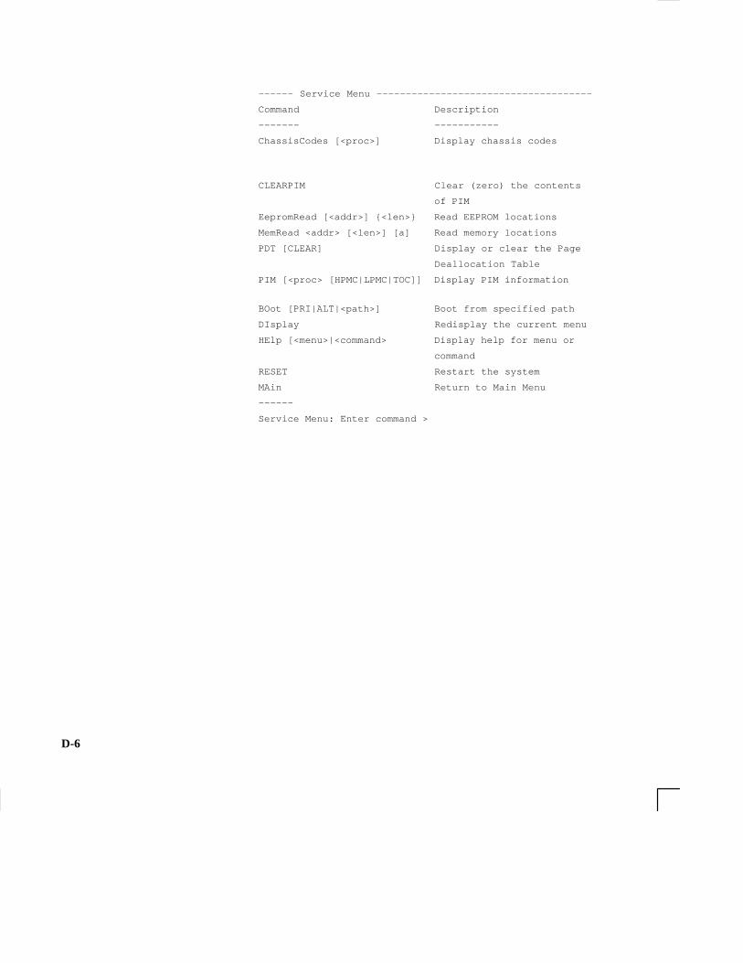
D-6
–––––– Service Menu –––––––––––––––––––––––––––––––––––––
Command Description
––––––– –––––––––––
ChassisCodes [<proc>] Display chassis codes
CLEARPIM Clear (zero) the contents
of PIM
EepromRead [<addr>] {<len>} Read EEPROM locations
MemRead <addr> [<len>] [a] Read memory locations
PDT [CLEAR] Display or clear the Page
Deallocation Table
PIM [<proc> [HPMC|LPMC|TOC]] Display PIM information
BOot [PRI|ALT|<path>] Boot from specified path
DIsplay Redisplay the current menu
HElp [<menu>|<command> Display help for menu or
command
RESET Restart the system
MAin Return to Main Menu
––––––
Service Menu: Enter command >
D-7
Accessing the Boot Console Interface
To access the boot console interface, follow these steps:
NOTICE: This procedure should be done by a system ad-ministrator.
1. Close any files and applications on your workstation.
2. Press the power switch on the front panel of the system unit.
NOTICE: There is no need to manually shut down theHP–UX operating system on your workstationbefore powering it off. When you turn off thepower switch, your workstation automaticallyshuts down the operating system before termi-nating the power.
Make sure that you do not unplug the system’s power cord or other-wise interrupt power to the system unit at this time.
3. When the system has completely shut down, power on yourworkstation.
If Autoboot is turned off, the boot sequence automatically stops at thebootconsole Main Menu.
If Autoboot is turned on, you will see the following messages:
Processor is starting Autoboot process. Todiscontinue, press any key within 10 seconds.
If Autoboot and Autosearch are both turned on, you will see the fol-lowing messages:
Processor is booting from first available de-vice.To discontinue, press any key within 10seconds.

D-8
NOTICE: If you are using a power–saving monitor, youwill have less than 10 seconds from the timethis message appears to press a key.
4. Press a key. You will then see the message:
Boot terminated
The Main Menu of the boot console appears.

D-9
Booting Your Workstation
Usually, you start your workstation by turning it on and waiting forHP–UX to boot automatically. However, you may not always wantthe usual sequence to occur.
For example, you may want to start your workstation from an operat-ing system that is stored on a device that is different from your usualboot device. If your normal operating system kernel or the disk onwhich it resides becomes damaged or unusable, you may wish to bootfrom a different disk or perhaps another type of device, such as aDDS–format tape drive.
Here are some situations and examples:
• If you know which device you want to boot from, and you knowthat it contains a bootable operating system, follow the direc-tions in ”Accessing the Boot Console Interface” earlier in thisappendix, and then type the following at the prompt:
Main Menu: Enter command > boot device
where device is the hardware path to the device, specified in Mne-monic Style Notation.
For example, if you wish to boot an operating system that is stored ona DDS–format tape in a drive that is located at ‘‘sescsi.1.0’’, followthe directions in ”Accessing the Boot Console Interface” earlier inthis appendix, and then type the following command at the prompt:
Main Menu: Enter command > boot sescsi.1.0

D-10
• If you do not know which device you want to boot from, thentype the following at the prompt:
Main Menu: Enter command > search
Path Number Device Path Device Type––––––––––– ––––––––––– –––––––––––P0 FWSCSI.6.0 HP C2490WDP1 SESCSI.1.0 HP HP35480A
Main Menu: Enter command > Boot P1
The operating system on the specified device is used to start yourworkstation (also see; Searching for Bootable Media).
• If you wish to interact with the Initial System Loader (ISL) be-fore booting your workstation, follow the directions in ”Acces-sing the Boot Console Interface” earlier in this appendix, andthen type the following at the prompt:
Main Menu: Enter command > boot device
You are prompted:
Interact with ISL (Y,N,Q)>
Answering yes (Y) causes the ISL to be loaded from the specifieddevice. After a short time, the following prompt appears on yourscreen:
ISL>
ISL is the program that actually controls the loading of the operatingsystem. By interacting with ISL, you can choose to load an alternateversion of the HP–UX operating system. If you do not want ISL to beloaded, you must enter N.
For example, if the usual kernel (/stand/vmunix) on your root disk(fwscsi.6.0) has become corrupted, and you wish to boot yourworkstation from the backup kernel (/stand/vmunix.prev), type thefollowing at the ISL> prompt:

D-11
ISL> hpux /stand/vmunix.prev
• If you do not know which media in your file systems have boot-able operating systems, you can find them with the search IPLcommand.
D-12
Searching for Bootable Media
To list devices that contain bootable media, follow the directions in”Accessing the Boot Console Interface” earlier in this appendix, andthen type the following at the prompt:
Main Menu: Enter command > search ipl
The search command searches all buses. The search may turn upmore devices than there are lines on your display. If you are using atext terminal, you may control the progress of the search from yourterminal’s keyboard by performing the following steps:
• To hold the display temporarily, press Ctrl S.
• To continue the display, press Ctrl Q .
• To halt the search, press any other key
These flow–control commands do not work with a bitmapped display,but such a display can show more than forty lines of text, so you areunlikely to need them.
To search for devices of just one type that actually contain bootablemedia, follow the directions in ”Accessing the Boot ConsoleInterface” earlier in this appendix, and then type the following at theprompt:
Main Menu: Enter command > search ipl device_type
where device_type is one of the following:
fwscsi is the built–in fast, wide SCSI bus.
sescsi is the built–in single–ended SCSI bus.
lan is all connections to the built–in LAN.
gscn is an optional fast, wide SCSI interface in slot number n.

D-13
Resetting Your Workstation
To reset your workstation to its predefined values, follow the direc-tions in ”Accessing the Boot Console Interface” earlier in this appen-dix, and then type the following at the prompt to access the Configu-ration Menu:
Main Menu: Enter command > co
When the Configuration Menu appears, type the following at theprompt:
Configuration Menu: Enter command > default

D-14
Displaying and Setting Paths
A path is the hardware address of a device that is attached to the I/Osystem of your workstation. The path command sets the system pathsshown in Table 5–8.
The path command sets and displays the hardware address of a speci-fied device attached to the I/O bus of your workstation.
Table 5–8. System Paths
Path Type Device
primary or pri Your workstation’s default boot device (usuallythe root disk)
alternate or alt Your workstation’s alternate boot device (usual-ly a DDS–format tape device)
console or cone Your workstation’s primary display device
keyboard or key Your workstaton’s primary input ASCII device
To display the current settings for the system paths, type the follow-ing at the prompt:
Main Menu: Enter command > path
The paths are displayed in Mnemonic Style Notation, as shown inTable 5–9.
Table 5–9. Mnemonic Style Notation for Boot Paths
I/O Type Specification Format
Built–in FWSCSI core.fwscsi.scsi_address.logical_unit_numberslotn.fwscsi.scsi_address.logical_unit_number
Built–in SCSI core.scsi.scsi_address.logical_unit_number
Built–in LAN core.lan.server_address.init_timeout.io_time-out
D-15
To display the current setting for a particular system path, follow thedirections in ”Accessing the Boot Console Interface” earlier in thisappendix, and then type the following at the prompt:
Main Menu: Enter command > path path_type
where path_type is one of the path types listed in Table 5–8.
For example, to get the path to the primary boot device, follow thedirections in ”Accessing the Boot Console Interface” earlier in thischapter, and then type the following at the prompt:
Main Menu: Enter command > path primary
To set a system path to a new value, follow the directions in ”Acces-sing the Boot Console Interface” earlier in this chapter, and then typethe following at the prompt:
Main Menu: Enter command > path path_type path
where path_type is one of the path types listed in Table 5–8 and pathis the specification of the path in Mnemonic Style Notation (as de-scribed in Table 5–9). For example, to set the primary boot path to aSCSI disk with an ID of 6.0, follow the directions in ”Accessing theBoot Console Interface” earlier in this appendix, and then type thefollowing at the prompt:
Main Menu: Enter command > path pri sescsi.6.0

D-16
Displaying and Setting the Monitor Type
Your system ships from the factory preset to use a monitor with a spe-cific resolution and frequency. If you replace your workstation’s mon-itor with a different type of monitor, you must reconfigure yourworkstation to support the new monitor.
The Monitor Command
The monitor command lets you change your workstation’s graphicsconfiguration. This command is available in Configuration Menu ofthe boot console interface.
NOTICE: The monitor command lets you change yourworkstation’s graphics configuration before youreplace your monitor. For information aboutchanging the configuration after you replaceyour monitor, refer to ”Changing Your MonitorType” in Appendix B.
To display the current graphics and console information, enter thefollowing command;
Main Menu: Enter command > co
Configuration: Enter command > mo
The correct usage for setting the graphics configuration is:
mo graphics_path type
where valid graphics_path parameters are:

D-17
graphics(0) through graphics(2) – Graphics adapters installed in op-tion slots 0 through 2 and type is the numerical monitor type.
For example, a Dual Visualize Enhanced Graphics Card (A4451A)installed in option slot 2 would be graphics(2A) and graphics(2B).

D-18
Displaying the Current Monitor Configuration
To display the current monitor configuration for your system from theConfiguration Menu of the boot console interface, follow the direc-tions in ”Accessing the Boot Console Interface” earlier in this appen-dix. Once you are in the Boot Console Interface Main Menu, enter:
Main Menu: Enter command > configuration
This places you in the Configuration Menu. From here, enter:
Configuration Menu: Enter command > monitor
The screen displays a list of the current graphics adapters and theremonitor types configured for your workstation.
MONITOR INFORMATION
Path Slot Head HPA Resolution Freq Type Class
––––––––– –––– –––– –––––– ––––––––––– –––– ––––– –––––
GRAPHICS(1) 1 1 f8000000 1280x1024 72Hz 12
Configuration Menu: Enter command >
In this example, only the graphics adapter(located in slot 1) graph-ics(1) is configured. The monitor type for graphics(1) is set to type12, which is a 1280 by 1024 monitor that uses a frequency of 72 Hz.

D-19
Setting the Monitor Type
You can set the monitor type for a graphics adapter by entering thefollowing:
Configuration Menu: Enter command > monitor graphics(n)tt
Where n is the number of the graphics adapter and tt is the monitortype.
To display a list of supported monitors, enter the following command:
Configuration Menu: Enter command > monitor list
A list of valid monitor types similar to the following is displayed:
MONITOR INFORMATION
Path Slot Head Type Size Freq Class
–––– –––– –––– –––– ––––––––– –––– –––––
GRAPHICS(0) 0 1 1 1280x1024 75Hz VESA
GRAPHICS(0) 0 1 2 1280x1024 75Hz VESA,Double
buffered
GRAPHICS(0) 0 1 3 1280x1024 75Hz VESA,Grey
scale
GRAPHICS(0) 0 1 4 1280x1024 75Hz VESA,Double
buffered,Greyscale
GRAPHICS(0) 0 1 5 1024x768 75Hz VESA
GRAPHICS(0) 0 1 6 800x600 75Hz VESA
GRAPHICS(0) 0 1 7 640x480 75Hz VESA
GRAPHICS(0) 0 1 8 1600x1200 75Hz VESA

D-20
GRAPHICS(0) 0 1 9 1600x1200 75Hz VESA,Grey
scale
GRAPHICS(0) 0 1 10 1200x1600 75Hz VESA
GRAPHICS(0) 0 1 11 1200x1600 75Hz VESA,Grey
scale
GRAPHICS(0) 0 1 12 1280x1024 72Hz
GRAPHICS(0) 0 1 13 1280x1024 72Hz Double buff
ered
GRAPHICS(0) 0 1 14 640x480 60Hz
GRAPHICS(0) 0 1 15 ––––––––user defined–––––––
Configuration Menu: Enter command >

D-21
To set the monitor type for graphics(0) to monitor type 2, enter thefollowing:
Configuration Menu: Enter command >monitor graphics(0) 2
This will take effect on the next reboot.
MONITOR INFORMATION
Path Slot Head HPA Resolution Freq Type Class
––––– –––– –––– ––––– –––––––––– –––– –––– –––––
GRAPHICS(0) 0 1 f8000000 1280x1024 72Hz 2
The boot console displays a message that tells you that your newmonitor selection will take affect the next time you reboot your sys-tem. The boot console also displays the new monitor information.
Trying to change the monitor type to a number not listed for thatgraphics device fails and gives you the following warning message:
Value of monitor type n out of range (n – nn)
Trying to change the monitor type on an empty slot fails and givesyou the following warning message:
No such graphics card.

D-22
Setting the Monitor Type at Power On
If you replace your workstation’s monitor with a different monitortype, and do not set the workstation’s graphics parameters by usingthe monitor command before doing so, you need to perform the fol-lowing:
Wait two seconds after the Num Lock light flashes near the end of theboot sequence, then press Tab to initiate the automatic monitor selec-tion process.
NOTICE: It takes approximately one to two minutes afterpowering on the workstation before the NumLock light flashes.
The system cycles through all of the available monitor types one at atime. When you can see a message similar to the following clearlyand legibly, select that monitor type by pressing Enter:
Path Slot Head Type Size Freq Class
––––– ––––– –––– –––– –––– –––– –––––
GRAPHICS(1) 1 1 n nnnnxnnnn nnHz
Press [RETURN] to select this monitor type(type n of n types).
The system queries you to confirm your selection. Press Y to savethis monitor type.
If you press any key other than Y, the following message is displayed:
Monitor type not saved.
At this point, the new monitor type is active, but not saved. Becauseyou didn’t save the monitor type, the next time you reboot the systemthe original monitor type will be used.
Next, the following message is displayed:

D-23
To select a new Graphics Monitor Type pressthe <TAB> key now, otherwise EXIT by enteringany other key (or will time out in 15 se-conds)...
To restart the monitor selection process,press TAB.
D-24
Displaying the Current Memory Configuration
The following sample screen output using the memory commandshows: first, a memory configuration table with properly–installedand configured memory (Sample Output 1); and second, output whena DIMM has been improperly installed (Sample Output 2).
To display the current memory configuration for your system, fromthe Information Menu of the boot console interface, follow the direc-tions in ”Accessing the Boot Console Interface” earlier in this appen-dix. Once you are in the Boot Console Interface Main Menu, type:
Main Menu: Enter command > information
This places you in the Information Menu. From here type:
Information Menu: Enter command > memory
The screen displays status and configuration information for thememory DIMMs installed in your workstation. The first listing belowshows the memory information for a system with correctly installedand configured memory modules. The second listing shows the in-formation for a system that has memory modules incorrectly installedor configured.

D-25
Memory Information Sample 1
The following sample shows the memory information when memorymodules are properly installed and configured:
MEMORY INFORMATION
MEMORY STATUS TABLE
Slot Size(a+b) Status
–––– ––––––––– –––––– 0a/b 64MB Configured
1a/b 32MB Configured
2a/b 128MB Configured
–––––––––
TOTAL 224MB
DETAILED MEMORY CONFIGURATION TABLE
SPA GROUP SMC SMC Status Bank Bank Status Size Slot
––– ––––– ––– –––––––––– –––– ––––––––––– ––––– ––––
0x00000000 1 0 Configured 1 Configured 64MB 2a/b
0 Configured 3 Configured 64MB 0a/b
0 Configured 1 Configured 64MB 2a/b
0x0c000000 0 2 Configured 0 Configured 16MB 1a/b
2 Configured 2 Configured 16MB 1a/b
Group 1 interleaved 2 ways over 3 banks
Group 0 interleaved 2 ways over 2 banks
BAD MEMORY TABLE

D-26
SMC SMC Status Bank Bank Status SIMM Size Slot
––– –––––––––– –––– ––––––––––– ––––––––– ––––
0 Present 0 Not Present 0MB 5a/b
2 Not Present 0MB 4a/b
1 Present 0 Not Present 0MB 5a/b
2 Not Present 0MB 4a/b
3 Not Present 0MB 0a/b
2 Present 1 Not Present 0MB 3a/b
3 Not Present 0MB 3a/b
Active, installed memory (bytes) : 234881024of Standard DRAM
Deallocated pages (bytes) – 0 ––––––––––
Available Memory (bytes) : 234881024
Good Memory Required by OS (bytes): 0(Not Set by OS)
Memory
HVERSION SVERSION
–––––––– ––––––––––
0x0710 0x0900

D-27
Memory Information Sample 2
The following sample shows the memory information when memorymodules are not properly installed and configured. In this sample thememory module in memory slot 1A is missing.
MEMORY INFORMATION
WARNING: Memory has been reconfigured due to aphysical change or because the
Page Deallocation Table (PDT) was cleared.This is for information only. No action is re-quired.
MEMORY STATUS TABLE
Slot Size(a+b) Status
–––– ––––––––– ––––––
0a/b 64MB Configured
1a/b ??MB SIMM not seated properly.
2a/b 128MB Configured
–––––––––
TOTAL 192MB
DETAILED MEMORY CONFIGURATION TABLE
SPA GROUP SMC SMC Status Bank Bank Status Size Slot
––– ––––– ––– –––––––––– –––– –––––––––– –––– ––––
0x00000000 0 0 Configured 1 Configured 64MB 2a/b
0 Configured 3 Configured 64MB 0a/b
1 Configured 1 Configured 64MB 2a/b
Group 0 interleaved 2 ways over 3 banks
BAD MEMORY TABLE

D-28
SMC SMC Status Bank Bank Status SIMM Size Slot
––– –––––––––– –––– ––––––––––– ––––––––– ––––
0 Present 0 Not Present 0MB 5a/b
2 Not Present 0MB 4a/b
1 Present 0 Not Present 0MB 5a/b
2 Not Present 0MB 4a/b
3 Not Present 0MB 0a/b
2 Present 0 Sizing Error 0MB 1a/b
1 Not Present 0MB 3a/b
2 Sizing Error 0MB 1a/b
3 Not Present 0MB 3a/b
Active, installed memory (bytes) : 201326592of Standard DRAM
Deallocated pages (bytes) – 0
–––––––––––Available Memory (bytes) : 201326592
Good Memory Required by OS (bytes): 0(Not Set by OS)
Memory
HVERSION SVERSION
–––––––– ––––––––––
0x0710 0x0900

D-29
Displaying the Status of the System I/O
The IO command lets you identify all built–in I/O devices and option-al I/O devices installed in the option slots. It is available in the In-formation Menu.
To use the IO command from the Information Menu of the boot con-sole interface, type:
Information Menu: Enter command > IO
Information about the built–in and optional I/O devices is displayed.
I/O MODULE INFORMATION
IODC IODC
Path Decimal Type Location HVER SVER Vers Dep
–––– –––––––– –––– –––––––– –––– –––– –––– –––
8/0 8/0 Bus Bridge built–in 6800 0a00 0x00 0x00
FWSCSI 8/12 A DMA I/O built–in 03b0 8980 0x96 0x00
8/16 8/16 Bus Adapter built–in 03b0 8100 0x00 0x00
8/16/0 8/16/0 Parallel built–in 03b0 7400 0x00 0x00
8/16/1 8/16/1 Audio built–in 03b4 7b00 0x00 0x00
SERIAL_1 8/16/4 RS232 built–in 03b0 8c00 0x01 0x00
SESCSI 8/16/5 SE SCSI built–in 03b0 8200 0x96 0x00
LAN 8/16/6 LAN built–in 03b0 8a00 0x02 0x00
PS2 8/16/7 Keyboard built–in 03b0 8400 0x00 0x00
8/16/8 8/16/8 Mouse built–in 03b0 8400 0x00 0x00

D-30
8/16/10 8/16/10 Floppy built–in 03b0 8300 0x00 0x00
8/20 8/20 Bus Adapter built–in 0170 8e00 0x00 0x00
SERIAL_2 8/20/2 RS232 Port built–in 0170 8c00 0x00 0x00
EISA 8/20/5 Bus Adapter built–in 0170 9000 0x00 0x00
GRAPHICS(0) 8/24 INTERNAL_EG_X128 built–in 0160 8500 0x01
0x00
8/63 8/63 Bus Converter built–in 5011 0c00 0x00 0x00
10/63 10/63 Bus Converter built–in 5011 0c00 0x00 0x00
EISA Cards
Path Type EISA ID
–––– –––– –––––––
8/20/5/1 EISA slot is empty
8/20/5/2 EISA slot is empty
8/20/5/3 EISA slot is empty
PCI Cards
Slot Path Bus Class
––––––––––––––––––––––––––––––––––––

D-31
Setting the Auto Boot and Auto Search Flags
auto boot and auto search are variables stored in your workstation’snonvolatile memory. (Nonvolatile memory retains its contents evenafter power is turned off.) If you reset these flags to new value, thechange takes effect the next time you reboot the workstation.
auto boot boots the operating system whenever your workstation isturned on.
To examine the state of the auto boot and auto search flags, type thefollowing at the prompt:
Configuration Menu: Enter command > auto
If auto boot is set to on, your workstation automatically attempts toboot the operating system when turned on. If auto boot is set to off,your workstation enters the boot administration mode of the boot con-sole user interface.
The state of the auto search flag determines how your workstationseeks a boot device during autoboot. If auto search is set to on, yourworkstation will search for other boot devices if the primary boot de-vice is not available. If auto search is off, your workstation will de-fault to the boot administration mode if it can’t see the primary bootdevice.
To change the state of the auto boot or auto search flags, type thefollowing at the prompt:
Configuration Menu: Enter command > auto bootstate
or
Configuration Menu: Enter command > autosearch state
where state is on or off.

D-32
Autosearch searches for devices in the following order:
Primary boot path
Alternate boot path
Built–in fast, wide SCSI devices
Built–in single–ended SCSI devices
Built–in LAN bootp servers
NOTICE: Fast wide SCSI adapter option cards installed inthe option slots are not searched unless they arereferenced by the primary or alternate bootpaths. EISA cards are not searched.
D-33
Displaying and Setting the Security Mode
The SECure flag is a variable stored in non–volatile memory. (Non–volitalmemory retains its contents even after power is turned off.) Ifyou reset this flag to a new value, the change takes effect the nexttime you reboot the workstation.
When the SECure flag is set to on, autoboot and autosearch areenabled and cannot be stopped. The system boots from the defaultboot paths regardless of user intervention.
To display the current setting for the SECure flag, enter the follow-ing command:
secure
To set the SECure flag on or off, enter one of the following:
secure on
secure off

D-34
Displaying and Setting the Fastboot Mode
When fastboot is enabled (set to on), your workstation does a quickcheck of the memory and skips I/O interface testing during its power–on self tests. This enables your workstation to complete its boot pro-cess quicker. The default factory setting is for fastboot to be enabled(on).
The fastboot mode allows your workstation to boot quickly by per-forming a less extensive check of the system’s memory.
When fastboot is disabled (set to off), more extensive memory test-ing and I/O interface testing is performed during the self tests, caus-ing the boot process to take longer.
If you are experiencing difficulty in booting your workstation, setfastboot to off and reboot the system. The more extensive testingmay reveal the error condition.
To display the status of fastboot, type the following at the prompt:
Configuration Menu: Enter command > fastboot
To disable fastboot, type the following at the prompt:
Configuration Menu: Enter command > fastboot off
To enable fastboot, type the following at the prompt:
Configuration Menu: Enter command > fastboot on

D-35
Displaying the LAN Station Address
It is sometimes necessary to supply a LAN station address of yourworkstation to other users. For example, if your workstation is to be-come a member of a cluster, the cluster administrator needs to knowyour LAN station address in order to add your workstation to thecluster.
A LAN station address of your workstation is the label that uniquelyidentifies the LAN connection for your workstation at the link level(the hardware level).
To display your workstation’s LAN station addresses, type the follow-ing at the prompt:
Information Menu: Enter command > lanaddress
The LAN station address is displayed as a twelve–digit number inhexadecimal notation, similar to the following:
LAN Station Addresses: 080009–789abc
The address is for the system’s built–in LAN.
Displaying System InformationThe all command allows you to display the system’s processor revi-sion and speed, cache size, memory size, flag settings, and the bootand console paths. To display system information from the Informa-tion Menu, type the following at the prompt:
Information Menu: Enter command > all
This information is paged to allow you to view it as necessary.
D-36
Displaying PIM InformationThe pim command allows you to display the most recent PIM in-formation for the specified fault type. To display PIM information fora specific fault, from the Service Menu, type the following at theprompt:
Service Menu: Enter command > pim processor_number
You can use pim in the following ways:
pim – gives all fault types
pim 0 – HPMC information on processor
pim 0 fault_type – fault type information on processor

�
�1!&"+ "�� 2
�1!&,#"�01."/�� �6�/-" &#& �0&,+/�� �6�
�1!&,� ,++" 0,./%"�!-%,+"/� ����� �6��*& .,-%,+"� ���� �6��
�
�,,0� ,+/,)"� &+0".#� "�� �6�
�,,0&+$� 0%"� /5/0"*�� #�&)1."�� ���� /,)2&+$� -.,�)"*/
�
������� !&/ / �."� ,#�� �6�),�!&+$�� �6�7�6�,2".2&"3�� �6�7�6�1+),�!&+$�� �6�7�6�
������� !.&2"�� �6��1/5� )&$%0�� �6��7�6�� ,+0.,)/� �+!� #"�01."/�� �67�6&+/0�))&+$� &+� /5/0"*� 1+&0�� �6��7�6��'1*-".� /"00&+$/�� �6��),�!&+$� �+!� 1+),�!&+$� �� !&/ �� �6�7�6�*,1+0&+$� �+!� 1+*,1+0&+$� �� !&/ �� �6��7�6��,-".�0&+$� ,+0.,)/� �+!� #"�01."/�� �6,2".2&"3�� �67�60.,1�)"/%,,0&+$�� �6��2".&+$� 0%"� ,+#&$1.�0&,+�� �6��
),/&+$� 0%"� /5/0"*� 1+&0�� �6�7�6�
,**�+!/ -&,�� 6���� 6�� /0*�� �6��"4&0�� �6� #�� (1-�� 6��#0&,�� 6��#0-�� �6�&,/ �+�� 6�*"!&�&+&0�� 6�*0�� 6��. -�� �6�.),$&+�� �6��0�.�� 6��� 6�0")+"0�� �6��2".�� �6��
,+#&$1.&+$� %�.!3�."�� �6� %�+$&+$� *,+&0,.� 05-"�� �6�� ),/&+$� 0%"� /5/0"*� 1+&0�� �6�7�6�&+/0�))&+$
������� !.&2"�� �6��7�6������ 0�-"� !.&2"�� �6� 7�6������� ,.� $.�-%& /� �,�.!�� �6��7�6��#),--5� !.&2"�� �6��7�6�%�.!� !&/(� !.&2"�� �6�7�6*�//� /0,.�$"� !"2& "/�� �6��7�6� *"*,.5�� �6 7�6
,-"+&+$� 0%"� /5/0"*� 1+&0�� �6�7�6
,++" 0,./�� /5/0"*� 1+&0� � -,3".�� �6���1!&,� %"�!-%,+"/������ �6���1!&,� *& .,-%,+"����� �6��("5�,�.!�� �6�*,1/"�� �6�+"03,.(�� �6��-�.�))")�� �6�������� �6�."�.� -�+")�� �6��7�6��������� �6�������� �6��/".&�)�� �6��/0".",� )&+"����� �6��/0".",� )&+"������ �6��
,+0.,)/�� /5/0"*� 1+&0#.,+0� -�+")�� �6�7�6�-,3".� /3&0 %�� �6
-&,� ,**�+!����#,.*�0� 0�-"� !.&2"�� 6��#),--5� !&/(� !.&2"�� 6��
/0*� ,**�+!�� �6��
�
���� 0�-"�. %&2&+$� !�0��� 6�)&/0&+$� #&)"/�� 6� ."/0,.&+$� #&)"/�� 6��0.�+/#"..&+$� !�0��� 6�3.&0&+$� 0,�� 6��
���� 0�-"� !.&2"�� 6� )"�+&+$� 0%"� 0�-"� %"�!/�� 6 76� ,+0.,)/� �+!� &+!& �0,./�� 676�&+/0�))&+$� &+� /5/0"*� 1+&0�� �6� 7�6��),�!&+$� �+!� 1+),�!&+$� �� !�0�� �//"00"�� 6�76��*"!&�� &+0". %�+$"��&)&05� ."/0.& 0&,+/�� 6��� 6��*"!&�� )&#"�� 6 76�,2".2&"3�� 676�0.,1�)"/%,,0&+$�� 6��76��
1/&+$� !"2& "� #&)"/�� �6��2".&+$� 0%"� ,+#&$1.�0&,+�� �6��
������� !�0�� ,*-."//&,+� *,!"�� /3&0 %� /"00&+$/��6��
������ 0�-"� !.&2"'1*-".� /"00&+$/�� �6������ &+!& �0,./�� �6�7�6
!&/-)�5� ,!"/�� �6�
������� 0�-"� !.&2"'1*-".� /"00&+$/�� �6� ���� &+!& �0,./�� �67�6
!&/-)�5� ,!"/�� �6
����#,.*�0� 0�-"�� 3.&0"�-.,0" 0� 0���� �6
����#,.*�0� 0�-"� !.&2"�� 3.&0"�-.,0" 0&+$� �� !�0� �//"00"�� �6
!"/ .&-0&,+� ,#� /5/0"*�� ���� /5/0"*� !"/ .&-0&,+
!"2& "� #&)"/� ,2".2&"3������� !.&2"�� �6����� 0�-"� !.&2"
,*-."//"!� *,!"�� �6�+,+ ,*-."//"!� *,!"�� �6��
#),--5� !&/(� !.&2"�� 6�
!, 1*"+0�0&,+� ,+2"+0&,+/�� 2&&
�
")" 0.,+& � *�&)�� ���� +"03,.(&+$�� *�&)
")" 0.,/0�0& � !&/ %�.$"� -." �10&,+/�� �67�6
"*&//&,+/� ."$1)�0&,+/�� �6�7�6
"4&0� ,**�+!�� �1--,.0��2"�� 6��
�
#�� (1-� ,**�+!�� ����#,.*�0� 0�-"� !.&2"�� �6�
�&)"� �.�+/#".� �.,0, ,)�� ���� #0-� ,**�+!
#),--5� !&/(� !.&2"�� 6� ,+#&$1.&+$� 0%"� #),--5� !.&2".�� 6��#,.*�00&+$� �� !&/("00"�� 6 76��&+/".0&+$� �+!� ."*,2&+$� �� !&/("00"�� 60.,1�)"/%,,0&+$�� 6��1/&+$� !"2& "� #&)"/�� 6�2".&+$� 0%"� ,+#&$1.�0&,+�� 676��3.&0"�-.,0" 0&+$� �� !&/("00"�� 6�76
#),--5� !&/("00"�. %&2&+$� !�0��� 6 76��#,.*�00&+$�� 6 76��)&/0&+$� #&)"/�� 6��
."/0,.&+$� #&)"/� 0,� /5/0"*�� 6�76��/�2&+$� #&)"/�� 6�0.�+/#"..&+$� !�0��� 6 76��3.&0"�-.,0" 0� 0���� 6�76
#),--5� !.&2"&+/0�))&+$� &+� /5/0"*� 1+&0�� �6��7�6��'1*-".� /"00&+$/�� �6��0".*&+�0,./�� �6��
#0&,� ,**�+!�� ����#,.*�0� 0�-"� !.&2"�� �6�
#0-� ,**�+!�� �6��
�
%�.!� !.&2"�!!&+$�� �6�7�6���00� %&+$� *,1+0&+$� �.� ("0�� �6�� ,+#&$1.&+$�� �6�&+/0�))&+$� &+� /5/0"*� 1+&0�� �6��7�6�'1*-".� /"00&+$/�� �6��
%�.!3�."� ,+#&$1.�0&,+�� ���� ,+#&$1.&+$� %�.!3�."
�
&*-,.0�+0� &+#,.*�0&,+�� �6��7�6��
&+!& �0,./����� /5/0"*� 1+&0�� �6����
������� !.&2"�� �6��7�6�������� 0�-"� !.&2"�� �6�7�6 ������� 0�-"� !.&2"�� �67�6 ."*,2��)"� !"2& "�� �6 /5/0"*� 1+&0�� �6
&+/0�))&+$� %�.!3�."������� !.&2"�� �6�7�6������ 0�-"� !.&2"�� �6��7�6������� ,.� $.�-%& /� �,�.!�� �6�7�6��#),--5� !.&2"�� �6��7�6��%�.!� !&/(� !.&2"�� �6��7�6�*�//� /0,.�$"� !"2& "/�� �6��7�6��
&+0.,!1 0&,+�� ���� /5/0"*� ,2".2&"3
&,/ �+� ,**�+!�� #),--5� !&/(� !.&2"�� 6
��� �!!."//� &+#,.*�0&,+�� �6��
�
'1*-"./�� ����� ��������� !.&2"�� �6�������� !.&2"�� �6��������� !.&2"�� �6�

%*-..6� #0(4$�� �7
�
)$6!- 0#� "-,,$"2-0�� 7�
�
������ ���� 7�
* 1$0� 1 %$26� 12 2$+$,21�� �7 8�7�
����� 1612$+� 3,(2�� 7�87�
���0$+-4 !*$� #$4("$�� 7�1612$+� 3,(2�� 7�87�
���1������� #0(4$�� 7�87������ 2 .$� #0(4$�� �7�8�7�#(1.* 6� "-#$1�� �7�
������� 2 .$� #0(4$�� �7�8�7�#(1.* 6� "-#$1�� �7�
*-&&(,&� (,�� %0-+� � 0$+-2$� 2$0+(, *�� ���� 0*-&(,� "-+7+ ,#
�
+ (*�� 7
+$#( � (,2$0"' ,&$ !(*(26� 0$120("2(-,1�� ���� 2 .$#0(4$�� �7�
+$#( (,(2� "-++ ,#�� %*-..6� #(1)$22$�� �7�
+$+-06� "-,%(&30 2(-,�� �7��8�7��
+$+-06� % (*30$1�� 78 7�
+$+-06� ������ 1$/3$,"$�� �7�
+-,(2-0"' ,&(,&� 26.$�� !--2� "-,1-*$� (,2$0% "$�� �7�1$22(,&� 2'$� 26.$�� 2� .-5$0� -,�� �7�
+-,(2-01�� 7�
+-3,2(,&� � ������� #(1"�� 7 87�
+-31$�� &$,$0 *� (,%-0+ 2(-,�� 7�
+-31$� "-,,$"2-0�� 7�
+2� "-++ ,#�� ����%-0+ 2� 2 .$� #0(4$�� �7�
�
,$25-0)� "-,,$"2-01�� 7
�$25-0)� �(*$� �612$+� ������� 7�
,$25-0)(,&� -4$04($5�� 787�%2.� "-++ ,#�� 7�+ (*�� 7�$25-0)� �(*$� �612$+� ������� 7�0".� "-++ ,#�� 7�0*-&(,� "-++ ,#�� 72$*,$2� "-++ ,#�� 7
�
-,�*(,$� '$*.".(-� "-++ ,#�� �7��� �7�"12+� "-++ ,#�� 7 %! ")3.� "-++ ,#�� �7�%*-..6� (,%-0+ 2(-,�� �7%2(-� "-++ ,#�� �7�%2.� "-++ ,#�� 7�+$#( (,(2� "-++ ,#�� �7+2� "-++ ,#�� �7�0".� "-++ ,#�� 7�0*-&(,� "-++ ,#�� 72 0� "-++ ,#�� �7��� �7�2$*,$2� "-++ ,#�� 7
-.$,(,&� 2'$� 1612$+� 3,(2�� �7�8�7�
-.$0 2(,&� 1612$+� -4$04($5�� 7�87�
-0#$0(,&� (,%-0+ 2(-,����%-0+ 2� 2 .$� " 11$22$1�� �7�%*-..6� #(1)$22$1�� �7
�
. 0 **$*� "-,,$"2-0�� 7
.-(,2(,&� #$4("$1�� &$,$0 *� (,%-0+ 2(-,�� 7�
.-5$0� "-,,$"2-0�� 7�
.-5$0� 15(2"'�� 1612$+� 3,(2�� 7�87�
.0-!*$+1�� ���� 1-*4(,&� .0-!*$+1
.0-#3"2� #$1"0(.2(-,�� ���� 1612$+� #$1"0(.2(-,
���� "-,,$"2-01�� 7�
�
/3$12(-,1�� 13&&$12(-,1�� -0� .0-!*$+1�� 4(((

�
+�*� �)''�(��� �2��
+�&��,�� �)�.'�(-,�� /
+�')-�&1� �)*1� #&�,�� ���� +�*� �)''�(�
+�')/��&�� �+#/�,�� �--��"#(!� ').(-#(!� �+��%�-��2�
+�')/��&�� '��#�������� �+#/��� �2����� -�*�� �+#/��� �2�� &)**1� �+#/��� �2��
+�/#,#)(� "#,-)+1�� /#
+&)!#(� �)''�(��� �2��
�������)((��-)+�� �2�*#().-�� �2�
�
,� �-1� �(�� +�!.&�-)+1� ,-�-�'�(-,�� /�� �2�
���� .-#&#-1���#(!� �� "�+�� �+#/��� �2�3�2���)( #!.+#(!� -"�� &)**1� �+#/�+�� 2��').(-#(!� �� ������� �#,��� �2�3�2��.(').(-#(!� �� ������� �#,��� �2��3�2�
�����,,#!(#(!� ��/#��� ��,
�,-�� 0#���� �2��3�2��,#(!&���(���� ,-�(��+��� �2��3�2��
�.,� &�(!-" �,-�� 0#��� �# �+�(-#�&�� �2��,#(!&���(���� ,-�(��+��� �2�
���&�,�� �2�)( #!.+�-#)(� �)(,-+�#(-,�� �2�
�,-�� 0#��� �# �+�(-#�&�� �2��)((��-#)(,�� �2��)((��-)+,� �(�� -�+'#(�-)+�� �2���/#��� ��,�� �2�3�2��*)+-� �)((��-#)(,�� �2��+�,-+#�-#)(,�� �23�2�
����� �.,�� �# �+�(��,�� �2�3�2
����� �)((��-)+,�� �2��
����� ��,�� $.'*�+,������� �+#/��� �2�������� �+#/��� �2��������� �+#/��� �2� &)**1� �+#/��� �2��
�������.,� &�(!-"�� �2��)( #!.+�-#)(� �)(,-+�#(-,�� ,#(!&���(���� ,-�(2
��+��� �2���-�+'#(#(!� �.,� &�(!-"�� �2�3�2��
,�+#�&�)((��-)+�� �2�*#().-�� �2�
,)&/#(!� *+)�&�',�� 2��))-� �#&.+��� 2��#(�#��-��� �1� -"�� ����� 2��32�'�')+1� �#&.+�,�� 2��32��*+)�&�',� �(�� ,)&.-#)(,�� 2�32�
�))-� �#&.+��� 2������� �+#/��� 2����� -�*�� �+#/��� 2 &)**1� �#,%� �+#/��� 2�"�+�� �#,%� �+#/��� 2�&)��#(!� �(�� �))-#(!� -"�� ���� 2(�-0)+%�� 2*)0�+#(!� .*�� 2�
,1,-�'� /�+# #��-#)(� -�,-,�� 2�32���.**)+-� �))&,� ��(�!�+�� 2�32��
,.�(�-0)+%� '�,%� #( )+'�-#)(�� �2��
�.**)+-� �))&,� ��(�!�+�� 2�32��
,0#-�"�,�� *)0�+�� �2�
,1,-�'� ��'#(#,-+�-#)(� '�(�!�+���#(!� �� "�+�� �+#/��� �2�3�2���)( #!.+#(!� -"�� &)**1� �+#/�+�� 2��').(-#(!� �� ������� �#,��� �2�3�2��.(').(-#(!� �� ������� �#,��� �2��3�2�
,1,-�'� ��,�+#*-#)(�� �2�3�2
,1,-�'� )/�+/#�0�� �2�
,1,-�'� .(#-�)((��-)+,�� �2��3�2���)(-+)&,�� �2�3�2������ �2�3�2������ �2�3�2�*)0�+� ,0#-�"�� �2�3�2�
,1,-�'� /�+# #��-#)(� -�,-,�� 2�32��
�
-�+� �)''�(����� )+'�-� -�*�� �+#/��� �2� &)**1� �#,%�--��� 2
-�&(�-� �)''�(��� �2��
-+).�&�,"))-#(!���� ����� ,)&/#(!� *+)�&�',������� �+#/��� �2��

���� #� �� �!�%��� �(��)�(��
��� '� ��"�� �!�%��� �(��
�
$���$�#���� �� ������� ��"��� �(�)�(��
�
%�!��'� ��������� �(�
�
&�!����� ���� ��$#���� "#�#����#"�� (