j. a1s y-pdf.usaid.gov/pdf_docs/pnaby101.pdf · energy technology innovation project prime...
TRANSCRIPT

P f\J. A1S y- IDt
t::f, \~ S. I I
UNITED STATES AGENCY FOR INTERNATIONAL DEVELOPMENT
DESIGN OF AN ASH DISPOSAL FACILITY FOR THEITABO I & II POWER PLANTS
Prepared forCORPORACI6N DOMINICANA DE ELECTRICIDAD
July 14, 1994

DESIGN OF AN ASH DISPOSAL FACILITYFOR THE ITABO I AND II POWER PLANTS
Prepared forCORPORACI6N DOMINICANA DE ELECTRICIDAD
July 14, 1994
Prepared byUSAID Office of Energy, Environment, and TechnologyEnergy Technology Innovation ProjectPrime Contractor: Bechtel Corporation
This report is funded by the U.S. Agency for International Development (USAID) to meet theEnvironmental requirements of The World Bank, The Inter-American Development Bank, andthe USAID with regard to the proposed activities for the Dominican Power Sector.
Energy Technology Innovation Project
Suite 914 • 1601 North Kent Street • Arlington, VA 22209 • Tel. (703) 528-4488 • Fax (703) 528-2280

u. S. AGENCY FOR INTERNATIONAL DEVELOPMENT
DESIGN OF AN ASH DISPOSAL FACILITYFOR THE
ITABO I & II POWER PLANTS
TABLE OF CONTENTS
1.0 EXECUTIVE SUMMARY. . . . . . . . . . . . . . . . . . . . . . . . . . . . .. 1
2.0 INTRODUCTION................................... 2
3.0 DESCRIPTION OF EXISTING ASH DISPOSAL PRACTICE . . . . . . . .. 33.1 BOTTOM ASH COLLECTION 33.2 FLY ASH COLLECTION AND DISPOSAL. . . . . . . . . . . . . .. 43.3 ASH DISPOSAL. 4
4.0 EVALUATION OF ASH QUANTITIES RESULTING FROM PLANTOPERATION . . . . . . . . . . . . . . . . . . . . . . . . . . . .. 5
5.0 EVALUATION OF THE POWER PLANT OPERATIONSAFFECTING ASH PARTICULATE EMISSIONS. . . . . . . . . . . . . . .. 8
6.0 CONSIDERATIONS FOR CONSTRUCTION OF ANENVIRONMENTALLY SOUND ASH DISPOSAL FACILITY 86.1 ALTERNATIVE METHODS FOR ASH TRANSPORT. . . . . . .. 86.2 DISPOSAL SITE MINIMIZATION . . . . . . . . . . . . . . . . . . .. 96.3 ENVIRONMENTAL REGULATIONS AND WATER QUALITY 106.4 RECOMMENDED DISPOSAL PRACTICES 116.5 DESIGN GUIDE FOR CONSTRUCTION OF AN
ENVIRONMENTALLY SOUND ASH DISPOSAL FACILITY. .. 11
7.0 CONCEPTUAL DESIGN OF AN ASH DISPOSAL FACILITY ANDCOST ESTIMATE . . . . . . . . . . . . . . . . . . . . . . . . . . . . . . . . . .. 137.1 CONCEPTUAL DESIGN OF AN ASH DISPOSAL FACILITY .. 137.2 COST ESTIMATE 14
Design of an Ash Disposal Facility for the Itabo 1 and 11 Power Plants

LIST OF TABLES
Table 4-1Table 4-2Table 4-3Table 7-1
Colombian Coal Analysis 5Calculated Quantities of Coal Used and Ash Generated on a Daily Basis 6Estimated Design Ash Quantity from the ltabo Plant . . . .. . 7Capital Cost Estimate for Ash Disposal Facility . . . . . . . . . . . . . . . 15
LIST OF FIGURES
Figure 7-1Figure 7-2
Conceptual Design of a Generic Ash Disposal Facility 16Conceptual Design of a Generic Ash Disposal Facility, Section Details. . . . . . . . . 17
APPENDICES
Appendix A Photographs of the Itabo Power Plant Ash Handling System and Existing Disposal Site................................................................ 18
Design ofan Ash Disposal Facility for the ltabo I and II Power Plants 11

DESIGN OF AN ASH DISPOSAL FACILITYFOR THE
ITABO I & II POWER PLANTS
1.0 EXECUTIVE SUMM:ARY
As part of its commitments under a joint power loan from the World Bank and theInter-American Development Bank, the Dominican Republic's Corporacion Dominicanade Electricidad (CDE) must design an ash disposal facility for the ltabo Power Plant.The improper disposal of ash - a byproduct of fossil fuel combustion - can causehealth, aesthetic, sanitary, and other environmental problems.
The USAID mission in Santo Domingo sponsored this project through a buy-in withUSAID's Office of Energy, Environment, and Technology. The Office of Energy,Environment, and Technology participated to lend expert assistance to the CDE foridentifying actions that should be taken and estimating the costs to effectively deal withthe ash disposal problem at the ltabo site.
The original objective of the study scope of work was to carry out site identificationand conceptual engineering for the construction of a new ash disposal facility for theexisting ltabo Power Plant. However, CDE has not been able to establish a definitivelist of potential ash disposal sites. Because potential sites cannot be identified at thistime, the report has been prepared with "generic" recommendations for a future ashdisposal site. The report assumes the new site will be located in a 5 to 10 km range ofthe ltabo Power Plant.
The scope of work, as modified, is to address the following specific task items:
• Evaluation of ash quantities resulting from the operation of the existing ltaboPower Plant.
• Evaluation of the Power Plant operations affecting ash particulate emissions.
• Considerations for construction of an environmentally sound ash disposalfacility.
• Conceptual design of an ash disposal facility and a cost estimate for the facilityconstruction.
The information presented in this report was based on observations made by ProjectTeam members during a trip to the Dominican Republic in April 1994, and pertinent
Design of an Ash Disposal Facility for the ltabo I and II Power Plants I

data provided by USAID and CDE personnel; no sampling or analysis were conductedby the Team.
Recommendations of the report are as follows:
• The design of the current ash system is appropriate and if properly maintainedand operated should be dust free. The discharge from the ash wetting drumcould be steamy or dusty. For dusty discharge the addition of a telescopic chuteis recommended.
• The current ash system urgently requires proper maintenance. Additionally, apreventive maintenance program must be implemented.
• The current ash disposal site is unacceptable because coal clean-up spillage ismixed with fly ash, household trash is dumped on the site, and the run-off wateris not controlled and drains directly into the ocean.
• Mixing coal spillage in the ash before or during disposal is not acceptable andmust be prevented.
• An ash toxicity study is required of the present and possible future coal sources.A long term coal contract is required. Coal purchased on-the-spot market maypresent an environmental problem.
• In the selection process of the final ash disposal site a soil and ground waterstudy must be conducted.
• The design of the ash disposal facility must be completed with a revegetationplan.
• A market study of the commercial utilization of the ash is recommended.
2.0 INTRODUCTION
As part of the preparation of a proposed Power Generation and InstitutionalRestructuring Project (power II Project), the Government of the Dominican Republic(GODR) must prepare an Environmental Assessment (EA) Report for the DominicanPower Sector.
As part of its commitments under the World Bank and Inter-American DevelopmentBank loan, the Corporaci6n Dominican de Electricidad (CDE) must control fugitiveparticulate pollution caused by the Itabo Power Plant coal operations and collected ashdisposal.
Design of an Ash Disposal Facility for the [tabo [ and II Power Plants 2

The report presents:
• An evaluation of the ash quantities generated as a result of the Itabo Plant'soperation when using coal as its primary fuel.
• An evaluation of the Power Plant operations affecting particulate emissions fromash handling practices in transporting and disposing of the ash.
• A description of ash handling/disposal methods currently practiced at the Itabosite.
• Considerations for mitigating the environmental impacts resulting from thetransport and disposal of the ash.
• Conceptual recommendations for the design of a new ash disposal facility.
The report includes a description and flow sheets of transportation methods andrecommended type of transport. It also contains a description of the method forbuilding the fly ash pile in an environmentally sound basis, as well as an estimate ofthe cost of such a facility (excluding the cost of land).
3.0 DESCRIPTION OF EXISTING ASH DISPOSAL PRACTICE
ltabo is a two unit 125MW dual fired (fuel-oil and coal) power plant located on thesouthern coast of the Dominican Republic, west of Santo Domingo. Unit I wascompleted in 1984 and is currently shut-down and undergoing extensive rehabilitation.Unit IT was completed in 1989 and operates as a base load unit. Unit II is currently (asof April 1994) firing on fuel-oil. The coal ash disposal site is located approximately 8km east of the plant. There are residential and agricultural activities near the existingcoal ash disposal facility.
The composition of ash from the coal-fired plants at Itabo I and IT is dependent upontype of feed coal, boiler configuration, and firing temperature. Particle size isdetermined by firing conditions and pollution control efficiency. The primary coalsource for existing coal-fired plants is Colombian coal, which is of medium quality.
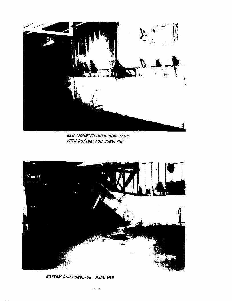
3.1 BOTTOM ASH COLLECTION
The bottom ash is continuously scraped from the quenching water by a drag type chainconveyor. The conveyor assembly with its enclosure is removable. From the chainconveyor the wet bottom ash drops on a flexowall steep angle type belt conveyor. Thecleats on the belt are short and there is a small clearance between the cleats and side
Design of an Ash Disposal Facility for the Itabo I and /l Power Plants 3
walls. Water drains from the belt and is dumped on the floor under the horizontalsection of the conveyor. The fmal dewatering stage of the bottom ash takes place inthe bottom ash truck loading silo. The bottom plate of the roll-away gate drains thewater into a gutter system and dumps it into the floor drain system (see Appendix A,photographs AI-A4).
The system design and equipment quality is better than average. The visible rust,however, indicates lack of preventive maintenance. As a result, the equipment life canbe expected to be shortened.
3.2 FLY ASH COLLECTION AND DISPOSAL
Fly ash from the electrostatic precipitator is conveyed by pneumatic conveyor through acyclone type separator to a collecting silo. Discharge air from the cyclone separatorpasses through a bag type air filter. The cleaned air is discharged from a dual blowersystem. The ash fines trapped in the bag filter are also discharged into the collectingsilo. A rotary mixer is provided to transfer the ash from the silo to the hauling truck.During transfer, water is mixed into the ash and it drops from the mixer into thehauling truck (see Appendix A, photographs A5-A7).
This arrangement appears to be well designed and assembled from quality equipment.Again, corrosion in vital locations is starting to show early deterioration of thecomponents. Most visible is the silo ring at the bottom of the fly ash collecting silo,which is used for support of the silo. Thick layers of rust and corrosion can be pealedfrom the flange of the ring. Other locations of corrosion are the small pipe flanges,pipes, operating chains, and valve activators. However, with proper maintenance, thecurrent fly ash removal system will function at an acceptable level for many years.
3.3 ASH DISPOSAL
Most of the hauling road from the plant to the ash disposal site is dirt and passesthrough populated areas. Transporting the ash in a wet condition, however, generallyprevents spillage and blowing dust (see Appendix A, photographs A8-A9).
At the ash disposal area, coal dust collected at the plant has been mixed into the ash fordisposal. Additionally, household wastes are mixed into the dumped piles of ash (seeAppendix A, photograph AID). Uncontaminated coal ash is normally not considered atoxic waste and thus may be easily disposed of. However, when mixed with coal dust,the material may be classified as toxic, and its disposal would be required to followapplicable rules for such a material. Because of uncontrolled drainage and run-off, thepresent dump is environmentally unsafe, its use should be discontinued as soon aspractical, and a new site should be selected (see Appendix A, photograph All).
Design of an Ash Disposal Facility for the lrabo I and II Power Plants 4

4.0 EVALUATION OF ASH QUANfITIES RESULTING FROMPLANf OPERATION
In general, the steam generators, fired with pulverized coal, produce ash ranging from7 to 25 percent of the consumed coal. A number of types of coals may be usedthroughout the plant life. The primary coal source for the existing ltabo Plant isColombian coal. Table 4-1 shows the analysis of coal samples extracted from threeseparate shipments received at ltabo.
Table 4-1 Colombian Coal Analysis
Sample 1 June 14-17, 1993 As Received DryEquivalent
Moisture Content (%) 12.68 <0.10Ash (%)
6.40 7.33Volatiles (%)
36.29 41.46Fixed Carbon (%) 44.63 51.11
Heat Content (BTUlIb) 11089 12699Sulfur (% by wt)
0.60 0.69
Sample 2 April 25-28, 1993 As Received DryEquivalent
Moisture Content (%) 7.53 <0.10Ash (%)
7.89 8.53Volatiles (%)
37.72 40.79Fixed Carbon (%) 46.86 50.68
Heat Content (BTU/lb) 12614 13641Sulfur (% by wt)
0.73 0.79
(conunued)
Design of an Ash Disposal Facility for the Itabo I and II Power Plallls 5

Table 4-1 Colombian Coal Analysis (cant.)
Sample 3 April 25-28, 1993 As Received Dry EquivalentMoisture Content (%) 12.62 <0.10Ash (%)
4.39 5.02Volatiles (%)
37.39 42.79Fixed Carbon (%)
45.60 52.19
Heat Content (BTUllb) 11484 13143Sulfur (% by wt)
0.56 0.64
Source: Reporte De AnaIisis No. 89-87424 & 89-86776, Los Analisis Realizados porCommercial Testing and Engineering Co., (SGS) en Kenner, La. USA.
Based on the analyses for Sample 2, the quantities of feed coal for the existing two unit125MW power plants and the corresponding ash production are shown in Table 4-2.
Table 4-2 Calculated Quantities of Coal Used and Ash Generated on a Daily Basis
I QUANTITIES I SAMPLE 1 I SAMPLE 2 I SAMPLE 3 IWet 2458 tid 2161 tid 2373 tidDry 2147 tid 1998 tid 2074 tidAsh 157 tid 170 tid 104 tidNote: Heat rate for the ltabo Plant is 10,018 Btu/Kwh.
Source: CDE Departamento de Planificaci6n, May 1994
The ash production, as shown in Table 4-2, varies between 104 and 170 tid. For theconceptual design of the ash disposal facility the ash production calculated for Sample 2was used. It is assumed for design purposes that 80 percent of the total ash is collectedas fly ash and 20 percent of the total is bottom ash. Table 4-3 shows the accumulatedyearly total ash production including both fly and bottom ashes. In Table 4-3, theyearly ash production rate is assumed to be constant.
Design of an Ash Disposal Facility for the jtabo I and 11 Power Plants 6
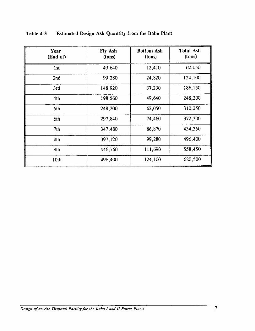
Table 4-3 Estimated Design Ash Quantity from the Itabo Plant
Year Fly Ash Bottom Ash Total Ash(End 00 (tons) (tons) (tons)
1st 49,640 12,410 62,050
2nd 99,280 24,820 124,100
3rd 148,920 37,230 186,150
4th 198,560 49,640 248,200
5th 248,200 62,050 310,250
6th 297,840 74,460 372,300
7th 347,480 86,870 434,350
8th 397,120 99,280 496,400
9th 446,760 111,690 558,450
10th 496,400 124,100 620,500
Design of an Ash Disposal Facility for the [tabo [ and II Power Plants 7

5.0 EVALUATION OF THE POWER PLANT OPERATIONSAFFECTING ASH PARTICULATE EMISSIONS
Presently, haul trucks are used to transport the bottom and fly ash from the plant to thedisposal facility. The load-out system includes a dewatering silo and load-out gate forthe bottom ash and a collecting silo with rotating wetting drum for the fly ash.
During truck loading the fly ash from the collecting silo is discharged into a rotarymixer. In the mixer the amount of water is adjusted to a level where dust is notliberated during truck loading at the plant and dumping the ash at the disposal site.The moisture content of the bottom ash after dewatering is also high which preventsparticulate emission. Except for incidental spillage of ash from the hauling trucks intransit from the plant to the ash disposal site, no particulate emission from the wet ashis expected.
The finished portion of the ash pile will be covered with a sloping cap of top soil andproperly vegetated. The active face of the ash pile will be periodically sprayed withwater, if required, and only negligible fugitive dust emission is expected.
6.0 CONSIDERATIONS FOR CONSTRUCTION OF ANENVIRomfENTALLY SOUND ASH DISPOSAL FACILITY
6.1 ALTERNATIVE METHODS FOR ASH TRANSPORT
Generally, power plant ash is handled and disposed of either wet (slurry) or dry(dewatered ash) systems. The following methods can be used for transporting ash froma power plant to a disposal site:
• Haul trucks (dry dewatered ash).
• Belt conveyor (dry dewatered ash).
• Pneumatic conveyor (dry dewatered ash).
• Slurry pipeline (ash mixed with water).
Compared with the slurry type ash disposal system, a dry ash disposal system has thefollowing advantages:
• More efficient use of available landspace, since the moisture content of the dryash can be adjusted for better compacting (higher densities).
• Lower construction cost.
Design of all Ash Disposal Facility for the Itabo J and JJ Power Plaflls 8

II
• Reclamation of landfJlI is generally less costly than reclamation ofimpoundment.
• There is more flexibility in plant operation and ash management.• Volume of leachate is reduced, thereby reducing any potentially adverse impacton ground water.
• Dry ash is more easily accessible for sale if the market demand for commercialuse increases.
Since ash hauling by truck is most cost effective, it is recommended that truckscontinue to haul bottom ash and fly ash from the plant to the selected new disposal site.Of the other dry ash handling methods, a belt conveyor and pneumatic conveyor arehigh cost options and are not recommended for Itabo.
6.2 DISPOSAL SITE MINIMIZATION
The ash disposal site can be minimized with an aggressive program for commercialutilization of the ash. Numerous research has been done and published by the AmericanCoal Ash Association, (1913 I St. NW. 6th FI. Washington, DC 20006) and theElectric Power Research Institute (3412 Hillview Avenue, Palo Alto, CA 94303).Some examples of the commercial use of ash are as follows:
Bottom ash
• Aggregate for bituminous road surfacing.
• Coating paper roof shingles.
• Fill material.
Fly ash
• Fly ash is being used commercially to a greater and greater extent. Its majorapplication is as an additive to concrete. By replacing approximately every fifthcubic foot of cement with one cubic foot of fly ash, a slower and cooler setting isproduced with equal or better strength than concrete without fly ash.• A mixture of fly ash, lime, and soil produces an exceedingly strong load carryingbase and is being used extensively for road building, parking areas, and airportlanding strips.
Design of an Ash Disposal Facility for the [tabo [ and 11 Power Plants9

• Considerable attention is being paid to the sintering (heating without melting) of flyash for producing light weight aggregate suitable for building blocks.
• The manufacture of wallboard blocks used for structures and buildings construction(see Appendix A, photograph A12).
• It is being used as structural fill for construction.
• Structures such as roller-compacted dams and precast buildings have used fly ash.
• Housing development and road resurfacing could be a good opportunity locally forcommercial use of ash.
Maximizing the industrial use of ash can be important both economically andenvironmentally. It reduces the permanent ash storage space and cost of ash disposal.Coal-fired power plant ash is currently considered a non-hazardous solid waste by theU.S. Environmental Protection Agency (EPA). However, ground water monitoring isgenerally required at the disposal site to verify that the water quality is not adverselyimpacted.
6.3 ENVIRONMENTAL REGULATIONS AND WATER QUALITY
In August 1993, the EPA signed a final regulatory determination that the coalcombustion by-products (fly ash, bottom ash, boiler slag, and flue gas emission controlwastes) generated at electric utility power plants do not present a significant danger tohuman health and the environment and so should not be regulated as hazardous wasteunder the Resource Conservation and Recovery Act (RCRA). However, EPA doesregulate coal combustion by-products as non-hazardous industrial wastes under Subtitleo of RCRA (58 CPR 1993).
The chemical composition of ash varies; however, trace amounts of heavy metals areoften present. The levels of elemental concentrations in ash leachate vary considerablyin US studies and leaching patterns are different for all elements depending on thesolubility properties of the constituents. Studies in the US have demonstrated theleaching potential of metals such as lead, arsenic, barium, cadmium, chromium,mercury, silver, and selenium in toxic quantities. l Therefore, contaminant levels ingroundwater leachate can be above water quality criteria, even though the levels oftoxic substances in ash piles may be significantly lower.
EPRI, 1983; Tripodi, et.al., 1980.
Design of an Ash Disposal Facility for the [tabo [ and 11 Power Plants 10

Subtitle D requirements generally translate into a site specific groundwater monitoringprogram, a bottom liner, and a cap cover system over the waste once the landfill isfilled to capacity. The cap cover system generally consists of several feet of soil withor without liner and a drainage system depending on the climatic conditions of the site.
6.4 RECOMMENDED DISPOSAL PRACTICES
Chemical analysis of the plant ash should be carried out to establish what, if any, is thetoxic level of the ash. This will determine if a liner should be placed under the ashdisposal site. The liner, if required, has to be compatible with the waste andchemically resistant for long-term performance. In the investigation of suitable linermaterials, the use of a concrete-like liner, composed of bottom and fly ash mixed withlime should be investigated first. This composition liner would consume long-term ashproduction. If the concrete-like liner is not compatible with the ash, the most suitableliner would be High Density Polyethylene (HDPE).
An impoundment landfill type disposal site is recommended. An impoundment pondwould be constructed adjacent to the disposal area, in the direction of rain runoff. Thepond would be sized to contain a ten year, 24 hour rainfall event. The collected waterquality would be monitored and, if required, chemically treated before discharging intothe environment.
Bottom ash and fly ash delivered to the disposal site should be dumped into separatepiles. This permits loading of ash customer's trucks with segregated unmixed ash.The accumulated left-over ash is periodically spread in 150 to 300 mm thickness andcompacted with rubber tired vehicles. The spread should be shaped so that the face issloping toward the impoundment pool.
The finished portions of the disposal pile should be reclaimed by covering the top withtop soil and vegetation.
6.5 DESIGN GUIDE FOR CONSTRUCTION OF AN El\rvIRONMENTALLYSOUND ASH DISPOSAL FACILITY
The following items have been considered for the design of a generic disposal site tomitigate dust emission, solid waste pollution, and water contamination. They are basedon the best available technology economically achievable.
• Provide a water spray truck for spraying water on the ash pile surface to reducedust emission.
Desigll ofall Ash Disposal Facility for the lrabo I and II Power Plallfs 11

• Provide a roll compactor for compacting the landfill to reduce dust emission andreduce rain erosion by stabilizing the ash pile.
• Provide a perforated pipe covered with bottom ash under the disposal area to reducecontamination of groundwater.
• Cover the ash pile with a compacted low permeable layer to reduce contaminationof surface and ground water. The low permeability layer should be a mixture of flyash with lime and soil.
• Reclaim the disposal site by covering the site with 300cm of sand and 600cm of topsoil, followed by planting with grass vegetation to reduce the surface erosion. Iftree vegetation is needed, a cap 105m thick of top soil, sand, and gravel is required.
• Provide a mixture of fly ash, lime, and soil about 20 cm thick to be paved on thetruck haul road to reduce dust emission.
• Spray water on the surface of the truck hauling road to reduce dust emission.
• Provide a tarp to cover the haul truck load to prevent dust emission.
• Make a 3 percent slope on the ash pile surface to be covered with the lowpermeable layer and guide the clean surface runoff water toward a separate drainsystem (directly dischargeable to the environment).
• Provide a run-off water retention pond to contain the ash pile run-off rainfall. Runoff water from the exposed portion of the ash pile should be retained in a pondsized for the maximum, ten year, 24 hour rainfall. The water should be monitoredand the surface oil skimmed before discharge to a water treatment plant. The pondshould be a low cost below ground excavated lined pond. A dam should not berequired. The liner should be 1.5mm HDPE.
• An ash toxicity study should be performed and, if required, provide a permanentwater treatment plant downstream of the run-off water pond for gradual treatmentof the collected run-off water. The water treatment plant should be a lined tankwith a chemical feed system, if required, to adjust pH, or to settle other undesirablesubstances before the water is discharged to the environment.
Design of all Ash Disposal Facility for the Itabo I and /I Power Plants 12
7.0 CONCEPTUAL DESIGN OF AN ASH DISPOSAL FACILITYAND COST ESTIMATE
7.1 CONCEPTUAL DESIGN OF AN ASH DISPOSAL FACILITY
A conceptual design of an ash disposal facility to be located on a generic disposal siteis shown in Figures 7-1 and 7-2. The drawings have been developed using the itemsfor consideration listed in Section 6.0 for construction of the ash disposal facility. Thedesign is based on the following:
• The estimated annual total ash production is 62,050 tly and is constant throughoutthe plant's life.
• The commercial utilization of ash to reduce the quantity of ash for the disposallandfill is not included. This is a conservative assumption to arrive at the size ofthe landfIll.
• The ash density is 0.75 tlm3 (wet) and 0.72 tlm\dry).
• The angle of repose of ash is 45° (wet) and 42° (dry).
• A generic site with a shallow dry gulch is assumed. If a deep canyon or largeravine is selected as the disposal site, the cost of ash landfill would be reducedbecause the disposal area is less.
• Top soil, sand, and gravel are locally available at a moderate cost.
Based on the design basis, the ash disposal volume is estimated to be 82,735 m3/y. Ifthe average landfill height is 10m, it will cover an area of 70m long by 120m wideeach year. The first year's landfill area is larger because the average landfill height isless than 10m. As shown in Figure 7-1, the ash disposal site is prepared with the topsoil removed. The top soil is used later to cover the ash pile for reclaiming. Aperforated drain pipe drain system covered with bottom ash is then installed. The ashpile starts at a high point of a dry gulch. A haul truck ramp with a slope of 10 percentis built at the high point. The ash dumping would proceed along the ridge of ash pile.A bulldozer works on the ash pile to form a grade of 1 to 3 (33 percent). A watertruck is provided for spraying the ash surface to reduce particulate emission, and theash pile is compacted with rubber-tired mobile equipment. When the ash pile reachesthe design height, the ash pile is immediately covered with an low permeable layer,which is a mixture of fly ash, sand, and lime. The run-off rainfall on the surfacecovered with the low permeable layer is guided to the ditches along the perimeter ofthe pile and directed to clean discharge.
Design ofan Ash Disposal Facility for the Itabo I and II Power Plants 13

II
In order to reduce the size of the run-off water pond and the corresponding watertreatment plant, several small ponds will be needed throughout the site lifetime. Asshown in Figure 7-1, the first pond is located at the end of the 3rd year ash pile and isdesigned to contain only the rainfall run-off water from the areas of the newly formedash pile (without impervious layer). The pond is 25m (W) x 25m (L) x 3m (deep) andis lined with 1.5 mm high density polyethylene (HDPE). As the ash piles proceed tothe first pond, a new pond would be excavated at a downstream location. The Figure7-1 shows the second pond atthe end of the fifth year ash pile.
7.2 COST ESTIMATE
An order-of magnitude cost estimate has been prepared for the proposed ash disposalfacility. Table 7-1 is based on the following assumptions:
• Cost factors are based on second quarter, 1994 U. S. dollars.
• The cost of Engineering, Procurement, and Construction Management (EPCM)services and contingency are estimated at 35 percent of the direct cost.
• The cost o-f major equipment items are based on recent quotations from U. S.suppliers.
Design of an Ash Disposal Facility for the ltabo I mul /l Power Plallls 14

Table 7-1: Capital Cost Estimate for Ash Disposal Facility
TOTALDESCRIPTION COST (,OOO's)
Haul Trucks l$ 400
Water Truck2135
Preparation ofLandfill Area 380
Cat. 825C Soil Compacto~ 450
Piping (installed)4 30
Perforated Pipe Drain System (installed)S 40
Truck Haul Road61,800
Runoff Water Pond 200
Water Treatment Plant 130
TOTAL DIRECT COSTS: $3,565
Engineering, Procurement, Construction Management (EPCM) andContingency (35% of Total Direct Costs) 1,248
II II
TOTAL COST $4,813
2
3
4
S
6
Cost is based on two haul trucks.Cost is based on one water truck.Cost is based on one soil compactor.Cost is based on 200m pipe length, diameter =300mm.Cost is based on 350m pipe length, diameter =300mm.Cost is conservatively based on 10km long road.
1!
Design ofan Ash Disposal Facilityfor the Itabo I and /I Power Plants 15

-- ~--,tPPRX. 100 m (FIRST YEM)70 m (S(C0t40 yEAR)70 m (THIRD YEAR)60 m (FirTH YEAR) 60 m 'fOURTH YEAR)
L.. ~.... ~I.... ..I.. ~I... ..I
DIRECTED WATERTO CLEAN QrSCH.ARGE B
•
~
\
::------.- HAUl TRUCKACCESS RAI.4P
A
,..~~
....CCESS
NATURAL GROUND
ASH rlU AT HIGH POINT
BPRISTINE WATERINTERCEPTOR DiTCH
)-- COt..4PACTlO COAl.
J r. SLOPE (TYP.)::--..
NEW ASH PILE
tAODITION~
TRUCK ACCESS
CH,4NNEL
'-- HOPE PIPE
~NATURAt.. GR,lDE
DIRECHO WATERTO CLEAN DISCHARGE
.....---------
"-- I I~
NATuR~
CRADE SLOPE
CHEMICAlr:=,FEED $YST(l,l
A
.....
0- _!-:'\- - - - - - - - - - - - - - - - - - - - - - -
~).:::........... L2~' mm '01A. HDPE PIPE <SOR20> L-..,---J
L 2nd SuRf ACERUNOfr WATER POND (fuTuRE) L 1 sl SURFACE RUNorF WATER
S( TTLE~ENT POND2~ m )( 25 m X J m
LINED WITH 1.5 nvn HDPERUN-OFF WATER
LREAT"EN! P,,,,T
(
!O
:.I
II
I
RUN-OFF WATERTRE .... TMENT PLANT
RUN-oFr WATER POND
SECTION A-A
•
iE ~I Bechtel Corporation ENERGY TECHNOLOGY,.." s", rR""'<SCO INNOVATION PROJECT
_OVAl. DAr! SCJrt.[ O.r.l( ,:_ "GURE 7 1
, "," ,~ ~.,,,,, .- CONCEPTUAl OE$lGN or A~ ~" ~"""'" • ... ' GENHllC ASH DISPOS.... r AGILITY
_ It{rrR{-'''C( Ofl' ........~ _. "'01[$ PV"ID< OI'lOrR '00 Ce-.lf"'(T .., :;;;=: ... 21615 J OOO-C-OOl A
7 ETIP-i_DGN /1u~ Jvn 28 199. 14e5212 IK(HAN)RA

A
-
55 m 10 m
I I ~ HAUL lRUCK ACCESS
~"'''i~ ~,,~,,~ .,"ASH LANOFILL GRASS VEG£T AllON ONL Y BE 1 10 J J
~ .-:.:.:-:-:-:.:.:- me '"' ".N
{OiTCH---..0:1 •
; ~" ., ••••• :, ., •.•.••- HIGH PERMEAELE MATERIAL~~;>/.,.0-1 ~ NATURAL GR.oDE ~. ;; .•••• ',.' •••• ' ••.• LOW PERMEAELE MATERIAL -120 m
SECTION C-C
SECTION 8-8
•tFLY & BOTTOM
BOTTOM ASH 7 ASH r-I
/ FRENCH DRAIN1m
• J
!, ~~~. DNATIvE SOIL
200 mm PERF ORATED PIPE W/ TOP SOIL RD.40VED
SECTION D-D-
~I Bechtel Corporation ENERGY TECHNOLOGY E
SAN fRANCISCO INNOVATION PROJECT/tPPffOv.... OAt( SU« DATE FIGURE 7-2. CONCEPTUAL DESIGN OF A
GENERIC ASH DISPOSAL r ACILI TV~'5U:() 1Q11t A:(P(llIIT;:'- SECTION OEl AILS" "'''''''''' .. - ,- RH(RrIolCt: O~""lHGS HO.II':CI~Dt>
T T"ANVIoIBO' NJl£S I'tACH.oqc:(R"'O CQNTIlJl:T NO ""OJ[CI_C'OIt< - II ko. 21615 OOO-C-002I I 2 I J I • • 5 I I 7 [TIPS,DeN lTue +n 28 1994 09012:23 IKCHANORA6

APPENDIX A
PHOTOGRAPHS OF THE ITABO POWER PLANTASH HANDLING SYSTEM AND
EXISTING DISPOSAL SITE
RAIL MOUNTED QUENCHING TANKWITH BOTTOM ASH CONVEYOR
BOTTOM ASH CONVEYOR· HEAD END
1\ 1

BOTTOM ASH CONVEYORTRANSFER STA TlON
CASING OF FLEXIBLE WAllBEL T CONVEYOR WITHDRAINAGE STATION ANDSERVICE OPENINGS
,'\ }

DRAINAGE GUTTERFROM ASH BIN
\
FlEXIBLE WAll CONVEYORTO BOTTOM ASH BIN

ASH BIN DRAINAGESYSTEM
TRAVELING DISCHARGE GA TE

flY ASH VALVE
flY ASH CONVEYING PIPE AND VALVE
'\ r1-__ 'j

I
FLY ASH SilO DISCHARGETO ROTARY MIXER
f-,-~
A- (.
Fl}' ASH SIl 0 WITHPRE·SEPARATOR ANDBA G HOUSE COllECTOR

ROTARY MIXER
MIXER PADDLES ANDSPRA Y NOZZLES

ASH OUMP PiA YGROlfNll
ASH PILE

WET flY ASH
.......... -
",.0-.~~
• +
--J
LEVElED Fl Y ASH
'- -
•
",- ......-., -..~,.....~

l
","b- __ .
.'';- .~
COAL AND HOUSEHOLD WASTE IN THE 4 :'iH
...._"- r~__
,
c
, ..
."~
.. '
'~fA",'.....~~.... ..."
" '
, "
I:4
')
~.~,., {'.
""....;
'_tr<~: -:f
-~1' "
,.is,~
'.'1'
I
~"
""
COAL SPIllAGE MIXED IN THE ASH

DIRECTION OFTOWARD T.H RUN OFt
E OCEAN
.., ......... " -

ASH CUSTOMER
~ I