j & d machine / hyperdrive / msa 3711 moon bend rd....
TRANSCRIPT
1
J & D Machine / Hyperdrive / MSA
3711 Moon Bend Rd.
Chapel Hill, TN 37034
www.HyperdriveRacing.com
You now own a state of the art 1/10 scale oval race car. The Hyperdrive Hustler has gone through months of testing by our factory drivers to insure that you get a car that has maximum performance and adjustability built in. In purchasing this kit you have not only helped the hobby and sport of Dirt Oval racing by supporting your local hobby shop but you have also bought the quality of a Hyperdrive Racing performance product. How well your car performs is dependant upon the assembly of your car kit. Take your time and assemble your car as shown in this manual. This will give you a good starting point from which you can make adjustments dependant upon the track you are racing on.
The following items are required to complete your car:
• Two channel Surface Radio
• Electronic Speed Control
• Shock Oil
2
• Tires
• Body
Tools needed in the construction of your car:
• Phillips Screwdriver
• Hobby Knife
• Allen Wrenches;3/32,1/16,5/64 & 0.050
• Pliers or appropriate sized Nut Drivers/Sockets
• 1/8” Reamer or Drill Bit
• Medium Sandpaper
Step #1: Take medium grit sandpaper and lightly
sand all edges of the graphite. Run a small bead of Super Glue around the sanded edges.
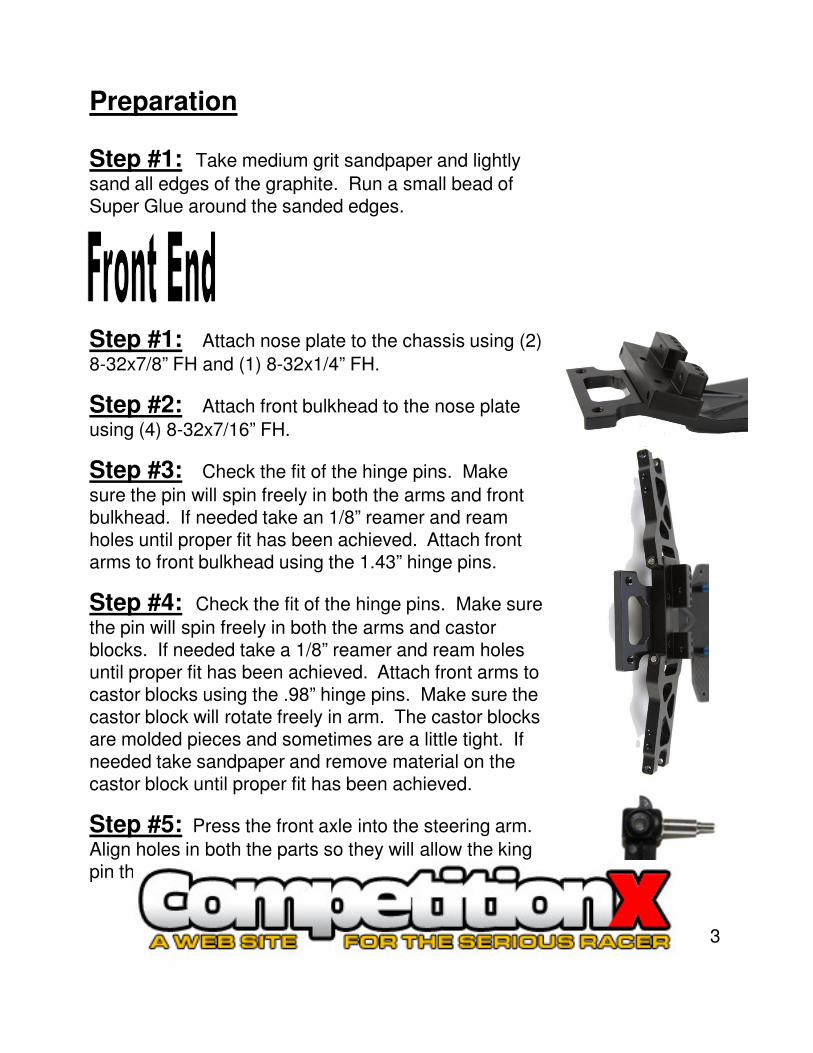
Step #1: Attach nose plate to the chassis using (2)
8-32x7/8” FH and (1) 8-32x1/4” FH.
Step #2: Attach front bulkhead to the nose plate
using (4) 8-32x7/16” FH.
Step #3: Check the fit of the hinge pins. Make
sure the pin will spin freely in both the arms and front bulkhead. If needed take an 1/8” reamer and ream
Preparation
3
bulkhead. If needed take an 1/8” reamer and ream holes until proper fit has been achieved. Attach front arms to front bulkhead using the 1.43” hinge pins.
Step #4: Check the fit of the hinge pins. Make sure
the pin will spin freely in both the arms and castor blocks. If needed take a 1/8” reamer and ream holes until proper fit has been achieved. Attach front arms to castor blocks using the .98” hinge pins. Make sure the castor block will rotate freely in arm. The castor blocks are molded pieces and sometimes are a little tight. If needed take sandpaper and remove material on the castor block until proper fit has been achieved.
Step #5: Press the front axle into the steering arm.
Align holes in both the parts so they will allow the king pin thru.
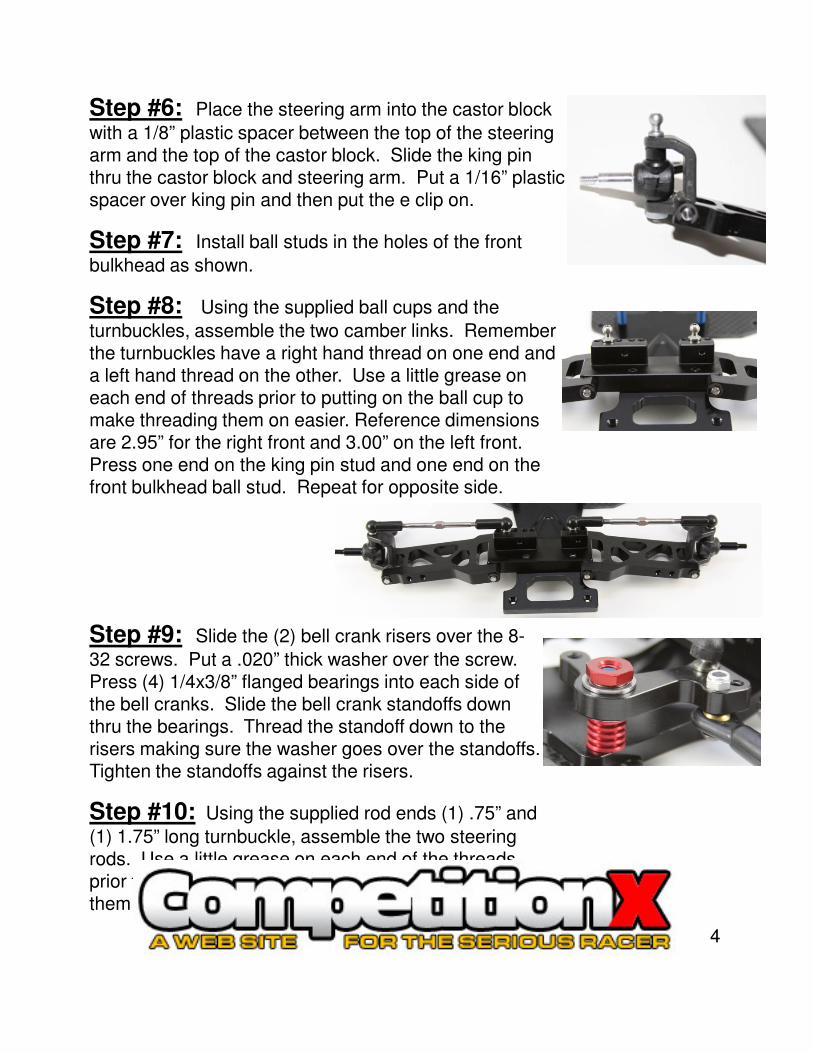
Step #6: Place the steering arm into the castor block
with a 1/8” plastic spacer between the top of the steering arm and the top of the castor block. Slide the king pin thru the castor block and steering arm. Put a 1/16” plastic spacer over king pin and then put the e clip on.
Step #7: Install ball studs in the holes of the front
bulkhead as shown.
Step #8: Using the supplied ball cups and the
turnbuckles, assemble the two camber links. Remember the turnbuckles have a right hand thread on one end and a left hand thread on the other. Use a little grease on each end of threads prior to putting on the ball cup to make threading them on easier. Reference dimensions are 2.95” for the right front and 3.00” on the left front. Press one end on the king pin stud and one end on the front bulkhead ball stud. Repeat for opposite side.
4
Step #9: Slide the (2) bell crank risers over the 8-
32 screws. Put a .020” thick washer over the screw. Press (4) 1/4x3/8” flanged bearings into each side of the bell cranks. Slide the bell crank standoffs down thru the bearings. Thread the standoff down to the risers making sure the washer goes over the standoffs. Tighten the standoffs against the risers.
Step #10: Using the supplied rod ends (1) .75” and
(1) 1.75” long turnbuckle, assemble the two steering rods. Use a little grease on each end of the threads prior to putting on the rod ends to make threading them on easier.
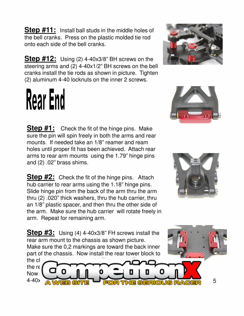
Step #11: Install ball studs in the middle holes of
the bell cranks. Press on the plastic molded tie rod onto each side of the bell cranks.
Step #12: Using (2) 4-40x3/8” BH screws on the
steering arms and (2) 4-40x1/2” BH screws on the bell cranks install the tie rods as shown in picture. Tighten (2) aluminum 4-40 locknuts on the inner 2 screws.
Step #1: Check the fit of the hinge pins. Make
sure the pin will spin freely in both the arms and rear mounts. If needed take an 1/8” reamer and ream holes until proper fit has been achieved. Attach rear arms to rear arm mounts using the 1.79” hinge pins
5
arms to rear arm mounts using the 1.79” hinge pins and (2) .02” brass shims.
Step #2: Check the fit of the hinge pins. Attach
hub carrier to rear arms using the 1.18” hinge pins. Slide hinge pin from the back of the arm thru the arm thru (2) .020” thick washers, thru the hub carrier, thru an 1/8” plastic spacer, and then thru the other side of the arm. Make sure the hub carrier will rotate freely in arm. Repeat for remaining arm.
Step #3: Using (4) 4-40x3/8” FH screws install the
rear arm mount to the chassis as shown picture. Make sure the 0,2 markings are toward the back inner part of the chassis. Now install the rear tower block to the chassis with (2) 4-40x3/8” FH screws. Then attach the rear tower to the block with (2) 4-40x5/16” BH. Now attach the other tower block to the tower using (2) 4-40x5/16” BH.
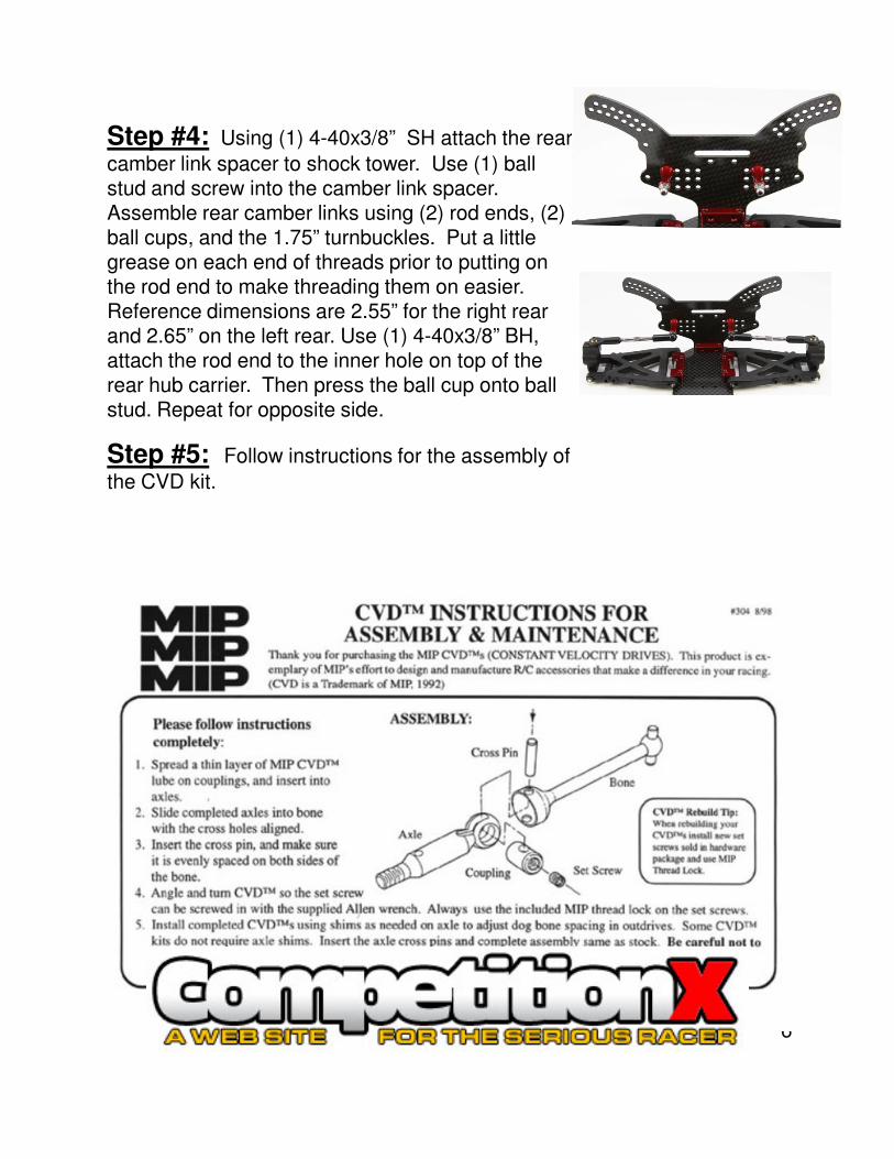
Step #4: Using (1) 4-40x3/8” SH attach the rear
camber link spacer to shock tower. Use (1) ball stud and screw into the camber link spacer. Assemble rear camber links using (2) rod ends, (2) ball cups, and the 1.75” turnbuckles. Put a little grease on each end of threads prior to putting on the rod end to make threading them on easier. Reference dimensions are 2.55” for the right rear and 2.65” on the left rear. Use (1) 4-40x3/8” BH, attach the rod end to the inner hole on top of the rear hub carrier. Then press the ball cup onto ball stud. Repeat for opposite side.
Step #5: Follow instructions for the assembly of
the CVD kit.
6
Step #6: Insert (2) 3/16x3/8 bearings into hub
carriers. Slide a .050” thick spacer over the axle. Insert axle thru the hub carrier’s bearings. Put a .020” thick spacer over the axle. Insert the drive roll pin. Repeat for opposite side. The hub carriers are a molded piece and may need to have the axle shimmed different to achieve the proper fit.
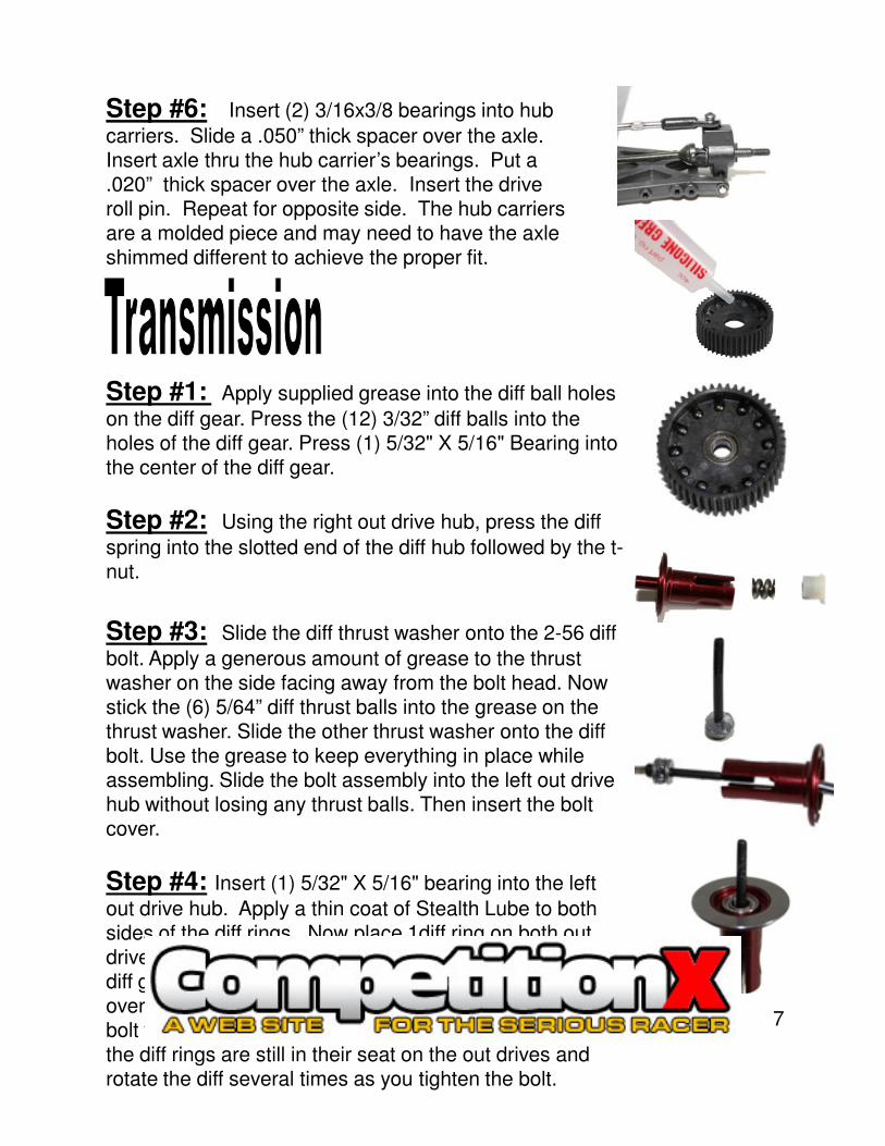
Step #1: Apply supplied grease into the diff ball holes
on the diff gear. Press the (12) 3/32” diff balls into the holes of the diff gear. Press (1) 5/32" X 5/16" Bearing into the center of the diff gear.
Step #2: Using the right out drive hub, press the diff
spring into the slotted end of the diff hub followed by the t-nut.
7
nut.
Step #3: Slide the diff thrust washer onto the 2-56 diff
bolt. Apply a generous amount of grease to the thrust washer on the side facing away from the bolt head. Now stick the (6) 5/64” diff thrust balls into the grease on the thrust washer. Slide the other thrust washer onto the diff bolt. Use the grease to keep everything in place while assembling. Slide the bolt assembly into the left out drive hub without losing any thrust balls. Then insert the bolt cover.
Step #4: Insert (1) 5/32" X 5/16" bearing into the left
out drive hub. Apply a thin coat of Stealth Lube to both sides of the diff rings. Now place 1diff ring on both out drives over the register in the face of the hub. Slide the diff gear onto the left out drive. Finally slide right out drive over the diff bolt and onto the diff gear. Tighten the diff bolt to the t-nut but not all the way. Check to make sure the diff rings are still in their seat on the out drives and rotate the diff several times as you tighten the bolt.
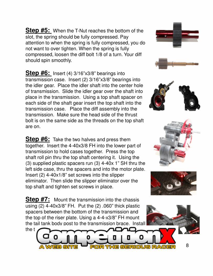
Step #5: When the T-Nut reaches the bottom of the
slot, the spring should be fully compressed. Pay attention to when the spring is fully compressed, you do not want to over tighten. When the spring is fully compressed, loosen the diff bolt 1/8 of a turn. Your diff should spin smoothly.
Step #6: Insert (4) 3/16”x3/8” bearings into
transmission case. Insert (2) 3/16”x3/8” bearings into the idler gear. Place the idler shaft into the center hole of transmission. Slide the idler gear over the shaft into place in the transmission. Using a top shaft spacer on each side of the shaft gear insert the top shaft into the transmission case. Place the diff assembly into the transmission. Make sure the head side of the thrust bolt is on the same side as the threads on the top shaft are on.
Step #6: Take the two halves and press them
8
Step #6: Take the two halves and press them
together. Insert the 4-40x3/8 FH into the lower part of transmission to hold cases together. Press the top shaft roll pin thru the top shaft centering it. Using the (3) supplied plastic spacers run (3) 4-40x 1” SH thru the left side case, thru the spacers and into the motor plate. Insert (2) 4-40x1/8” set screws into the slipper eliminator. Then slide the slipper eliminator over the top shaft and tighten set screws in place.
Step #7: Mount the transmission into the chassis
using (2) 4-40x3/8” FH. Put the (2) .060” thick plastic spacers between the bottom of the transmission and the top of the riser plate. Using a 4-4-x3/8” FH mount the tail tank body post to the transmission brace. Install the transmission brace using (4) 4-40x5/16” BH.
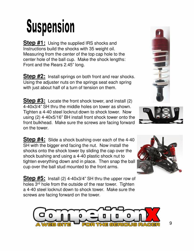
Step #1: Using the supplied IRS shocks and
Instructions build the shocks with 35 weight oil. Measuring from the center of the top cap hole to the center hole of the ball cup. Make the shock lengths: Front and the Rears 2.45” long.
Step #2: Install springs on both front and rear shocks.
Using the adjuster nuts on the springs seat each spring with just about half of a turn of tension on them.
Step #3: Locate the front shock tower, and install (2)
4-40x3/4” SH thru the middle holes on tower as shown. Tighten a 4-40 steel locknut down to shock tower. Now using (2) 4-40x5/16” BH install front shock tower onto the front bulkhead. Make sure the screws are facing forward on the tower.
9
on the tower.
Step #4: Slide a shock bushing over each of the 4-40
SH with the bigger end facing the nut. Now install the shocks onto the shock tower by sliding the cap over the shock bushing and using a 4-40 plastic shock nut to tighten everything down and in place. Then snap the ball cup over the ball stud mounted to the front arms.
Step #5: Install (2) 4-40x3/4” SH thru the upper row of
holes 3rd hole from the outside of the rear tower. Tighten a 4-40 steel locknut down to shock tower. Make sure the screws are facing forward on the tower.
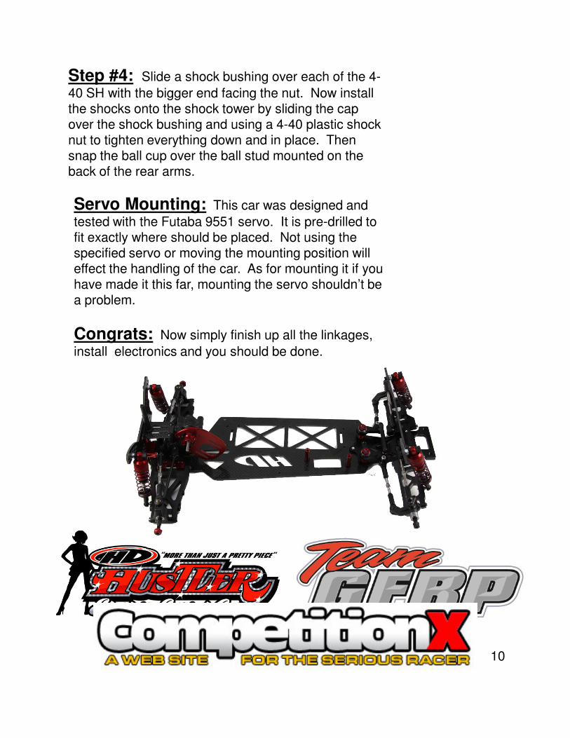
Step #4: Slide a shock bushing over each of the 4-
40 SH with the bigger end facing the nut. Now install the shocks onto the shock tower by sliding the cap over the shock bushing and using a 4-40 plastic shock nut to tighten everything down and in place. Then snap the ball cup over the ball stud mounted on the back of the rear arms.
Servo Mounting: This car was designed and
tested with the Futaba 9551 servo. It is pre-drilled to fit exactly where should be placed. Not using the specified servo or moving the mounting position will effect the handling of the car. As for mounting it if you have made it this far, mounting the servo shouldn’t be a problem.
Congrats: Now simply finish up all the linkages,
install electronics and you should be done.
10