j. david rogers, ph.d., p.e., p.g. - missouri s&tweb.mst.edu/~rogersda/levees/historic...
TRANSCRIPT

Historical Background Historical Background on the New Orleans on the New Orleans
Levee SystemLevee System
J. David Rogers, Ph.D., P.E., P.G.J. David Rogers, Ph.D., P.E., P.G.Karl F. Karl F. HasselmannHasselmann Chair in Geological EngineeringChair in Geological Engineering
and Associate Directorand Associate DirectorNatural Hazards Mitigation InstituteNatural Hazards Mitigation Institute
University of MissouriUniversity of Missouri--RollaRolla

• Typical cross section through the sandy bank levees of the Mississippi River, illustrating how the river’s main channel lies above the surrounding flood plain, which were poorly drained swamp lands prior to reclamation.
• There is significant hydraulic sorting of materials deposited on either side of these levees, as sketched below.

• Natural levees exist along most perennial channels subject to periodic overbank flooding emanating from a prominent low flow channel, as sketched above. Man-made levees originated by piling up additional earthen fill on top of these natural levees (from Press and Siever, 1997) .

• Union forces cutting the levee near the state line of Louisiana and Arkansas, 20 miles above Lake Providence during the Civil War.
• Levees constructed of cohesive clay were found to be the most resilient, but those constructed of other materials, such as overbank silt, peat, or organic ooze were easily eroded.

• Asymmetric channel cross section typical of the Mississippi River, showing slumping of the oversteepened banks on the outside of its turns and the relative position of the river’s thalweg, the line connecting the lowest points along the bed of the river. River mileage is measured along the thalweg, not along the river centerline, because this line more accurately describes the actual flow path (from Fisk, 1952).

• Map showing the lands inundated in Louisiana during the height of the great Mississippi River Flood of 1927. Concerns over long term safety from flooding caused many businesses and financial institutions to depart New Orleans to seemingly safer havens, such as Houston, TX.

• Cross section through a typical Corps of Engineers levee in an alluvial valley (from Mansur and Kaufman, 1956).
• Analyses of levee stability depend in large measure on various assumptions made about seepage conditions beneath and adjacent to such structures.
• For instance, the coarse sand and gravel shown here may be 1000x more permeable than the overlying medium sand.

• A major problem with man-made levees constructed during the MR&T Project is that they are necessarily constructed upon highly heterogeneous foundations, as portrayed here (taken from Kolb, 1976).
• The sharp contrast between highly organic channel fills (stippled zones) and natural levee sands and gravelly point bars promotes dangerous concentrations of seepage and differential settlement.

• Map showing principal elements of the Mississippi River & Tributaries Project flood control for the lower Mississippi River Delta region.
• Note the much shorter flow channel to the Gulf of Mexico along the Atchafalaya River as opposed to the Mississippi River. The Mississippi River would have switched to this channel by 1975 if the Old River Control Structure had not been constructed in 1961-63.

• This cross section illustrates how much of New Orleans lies below mean gulf level, requiring every drop of rain water to be pumped out.
• The height of the Mississippi River levee is 24.5 ft while the Lake Pontchartrain levee crests at 13.5 ft (from Kolb and Saucier, 1982).

• Stage hydrographs on Lakes Borgne and Pontchartrain from the September 1947 hurricane.
• The 10 foot surge on Lake Borgne was the highest recorded value up to that time, though short-lived.
• A 13 foot surge was reported along Lake Pontchartrain during the 1915 Grand Isle Hurricane (before storm surge recorders were emplaced).
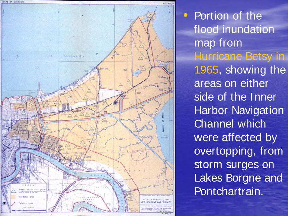
• Portion of the flood inundation map from Hurricane Betsy in 1965, showing the areas on either side of the Inner Harbor Navigation Channel which were affected by overtopping, from storm surges on Lakes Borgne and Pontchartrain.

• South Lake Pontchartrain flood protection measures authorized by Congress in the wake of Hurricane Betsy in 1965. These included heightening of the protective levees along the IHNC and the Lake Pontchartrain shoreline to the Orleans-Jefferson Parish boundary, and around Chalmette in St. Bernard’s Parish.
• This system was subsequently enlarged to include the Pontchartrain levee all the way to the Bonne Carré Spillway and along the principal drainage canals in New Orleans and Jefferson Parishes.

• Plan of the City of New Orleans prepared by Francis Ogden in 1829. Note the linear drainage canals feeding into Bayou St. John, thence into Lake Pontchartrain.

• This 1849 map of New Orleans shows the extensive cypress swamps lying between the uptown and French Quarter areas and Lake Pontchartrain.
• The map shows the projected path of the 17th Street Canal between Orleans and Jefferson Parishes, which was constructed in 1857-58.

• By 1863 there were a series of east-west feeder canals serving Bayou St. John from the west side and a series of north northeasterly trending drainage canals in St. Bernard Parish.

• All 36 miles of drainage canals in the Lakeview and Gentilly areas are shown in this portion the 1878 Hardee Map. The canals are, from left: 17th Street, New Basin (infilled), Orleans, Bayou St. John, and London Avenue, and the Lower Line Protection Levee.

• Photo taken in 1890 looking north along the “shell road” than ran along the west side of the New Basin Canal, seen at extreme right.
• Note the modest height of the embankment, no more than 5 feet above the adjacent cypress swamp. The canal embankments were heightened after hurricane-induced overtopping in 1915 and 1947.

• Cross section through New Orleans prepared by City Engineer L. W. Brown in 1895 (from the Historic New Orleans Collection).
• This shows the elevated position of the Mississippi River and the Metairie-Gentilly Ridge distributarychannel, which lies 3 to 6 feet above the surrounding area.
• The green lines denote high and low levels in the river and Lake Pontchartrain. Elevations are in the old Cairo Datum (21.26 ft above MGL).
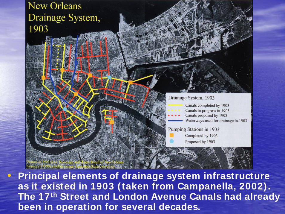
• Principal elements of drainage system infrastructure as it existed in 1903 (taken from Campanella, 2002). The 17th Street and London Avenue Canals had already been in operation for several decades.

• S&WB engineer A. Baldwin Wood standing next to one of his 14-foot diameter screw pumps in 1929 with several of the board’s secretaries sitting inside the housing for scale (courtesy of the Sewerage & Water Board of New Orleans).
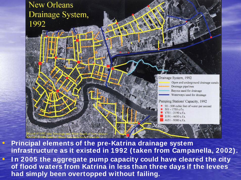
• Principal elements of the pre-Katrina drainage system infrastructure as it existed in 1992 (taken from Campanella, 2002).
• In 2005 the aggregate pump capacity could have cleared the city of flood waters from Katrina in less than three days if the levees had simply been overtopped without failing.

Problem with houses next to leveesProblem with houses next to levees
• Evolution of the Corps of Engineers’ standard levee section, 1882 to 1972 (from Moore, 1972).
• Earth embankments levees are generally heightened sequentially by compacting additional soil on the land side of the embankments(each sequence of heightening shown as different colors).
• Levees adjacent to drainage canals or perennial channels are notraised on the river side of the embankment because excess moisture would prevent meaningful compaction of the fill.
• Existing homes abutted the land side of the drainage canal levees in New Orleans by the time the Corps of Engineers began analyzing them in the 1960s.
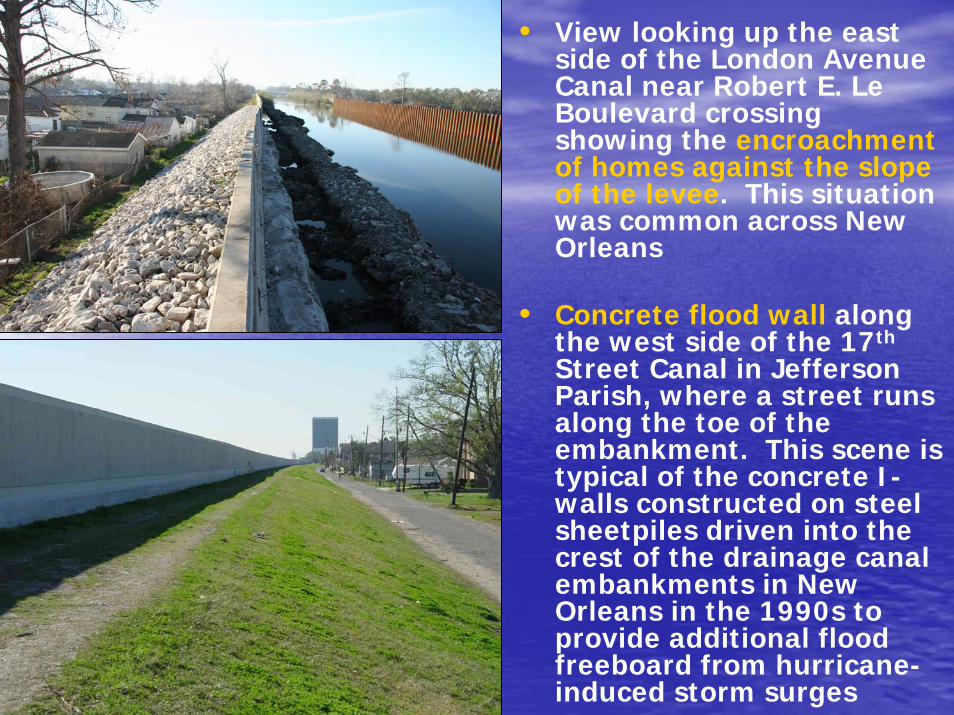
• View looking up the east side of the London Avenue Canal near Robert E. Le Boulevard crossing showing the encroachment of homes against the slope of the levee. This situation was common across New Orleans
• Concrete flood wall along the west side of the 17th
Street Canal in Jefferson Parish, where a street runs along the toe of the embankment. This scene is typical of the concrete I-walls constructed on steel sheetpiles driven into the crest of the drainage canal embankments in New Orleans in the 1990s to provide additional flood freeboard from hurricane-induced storm surges

• Assumed Category 3 storm surge curvesfor the Gulf of Mexico shoreline, Lake Borgne, and Lake Pontchartrain used by the Army Corps of Engineers for planning and design purposes prior to Hurricane Katrina in 2005.
• Note the short duration of extreme surges, about 12 hours duration above 5 ft MGL for Lake Pontchartrain.

• Schematic layout of levees and flood walls protecting the New Orleans area at the time Hurricane Katrina struck on August 29, 2005 (from image by the New York Times). Red arrows denote locations of levee failures.

• Incomplete record of the Lake Pontchartrain tidal stage gage at West End, near the mouth of the 17th Street Canal during the early stages of Hurricane Katrina (from U.S. Geological Survey).
• This record shows several steps in the storm surge, known as “ramping,” beginning on August 28th, with the sharpest increase on the morning of August 29th, when the hurricane made landfall. The gage failed when the lake level reached 5.3 ft, before the peak surge was recorded.

• Localized deflection of the west flood wall on the Jefferson Parish side of the 17th Street Drainage Canal, opposite the breach that occurred on the eastern side on August 29, 2005.
• The gap formed at the construction joint was wider at the base than the crest, suggesting deep-seated strain beneath the embankment (photo looking north).

• Most of the IHNC was constructed using mobile dragline excavators like the one pictured here building the Morrison-Picayuneville Levee about 25 miles south of New Orleans in June 1931.
• Tower draglines could excavate materials up to a quarter mile away, dragging it back up onto the new levee.

• Aerial oblique view of the Inner Harbor Navigation Canalbetween 1960-64, after the entry to the Mississippi River-Gulf Outlet Channel had been enlarged (upper right), connecting to the inner harbor area.

• Seepage crevasse splay exposed on the water side of the east levee of the IHNC breach after Hurricanes Katrina and Rita. This same section of the IHNC levee failed in 1965 during Hurricane Betsy.
• Levees tend to fail during sustained high flow events because of underseepageproblems, toe scour, and overtopping. Note the anomalous seepage in lower foreground, which suggests much higher permeability in this particular portion of the dike, close to the south end of the failed section.

• Portion of a map of the upper MRGO channel adjacent to Lake Borgne from the report by Coastal Environments, Inc. (1984).
• This shows the major soil subdivisions they identified: soft marsh, firm marsh, and swamp substrate. Much of this material was unsuitable for using in the adjoining levee embankments.
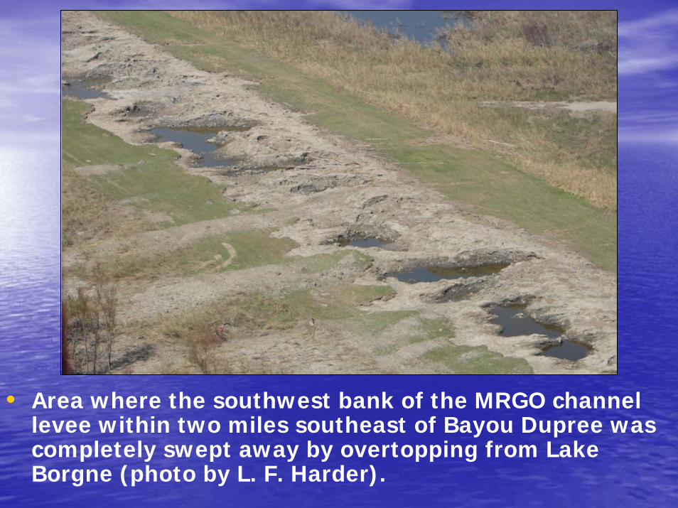
• Area where the southwest bank of the MRGO channel levee within two miles southeast of Bayou Dupree was completely swept away by overtopping from Lake Borgne (photo by L. F. Harder).

Datum Conversion to Mean Sea Level 1929Ellet Datum of 1850 unknownDelta Survey Datum of 1858 0.86Old Memphis Datum of 1858 -8.13Old Cairo Datum of 1871 -21.26New Memphis Datum of 1880 -6.63Mean Gulf Level Datum (preliminary) 1882 0.318Mean Gulf Level Datum of 1899 0New Cairo Datum of 1910 -20.434Mean Low Gulf Level Datum of 1911 -0.78
• Table relating correction factors used when comparing various historic datums in the New Orleans area (Denny, 2002).
• Blanket corrections can no longer be made to adjust elevations to NAVD88-2004.65, which is the most oft cited datum currently used in New Orleans. The reason for these disparities is the gross differential settlement between reference benchmarks, which can be significant (order of magnitude difference).
SERIOUS DATUM PROBLEMSSERIOUS DATUM PROBLEMS