j frame - series moulded case circuit breakers · 2016. 10. 10. · j-series-dat oct 2016 data...
TRANSCRIPT
low voltage
J-SERIES-DATOCT 2016
Data SheetPage 1 of 14
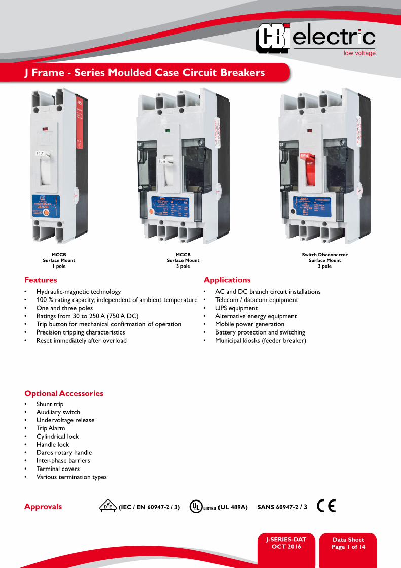
J Frame - Series Moulded Case Circuit Breakers
Switch DisconnectorSurface Mount
3 pole
MCCBSurface Mount
3 pole
MCCBSurface Mount
1 pole
• Hydraulic-magnetic technology • 100 % rating capacity; independent of ambient temperature• One and three poles• Ratings from 30 to 250 A (750 A DC)• Trip button for mechanical confirmation of operation• Precision tripping characteristics • Reset immediately after overload
Features Applications• AC and DC branch circuit installations• Telecom / datacom equipment • UPS equipment • Alternative energy equipment• Mobile power generation • Battery protection and switching• Municipal kiosks (feeder breaker)
• Shunt trip• Auxiliary switch• Undervoltage release• Trip Alarm• Cylindrical lock• Handle lock• Daros rotary handle• Inter-phase barriers• Terminal covers• Various termination types
Optional Accessories
Approvals (IEC / EN 60947-2 / 3) (UL 489A) SANS 60947-2 / 3

J-SERIES-DATOCT 2016
Data SheetPage
low voltage
2 of 14
J Frame - Series Moulded Case Circuit Breakers
Technical Data
Product Type Circuit BreakerJS25
Circuit BreakerJ25S
Switch DisconnectorJ25SN
Standard Ampere Ratings (A) – AC 30 - 250 A 30 - 250 A 100 - 250 AStandard Ampere Ratings (A) – DC 80 - 250 A 300 - 750 ANumber of Poles 1 3 3Rated Interrupting / Withstand Capacity (kA)Tripping Curve JS JS -
TerminationsStandard G1 lug terminal up to 150 A; G4B stub busbar above 150 A
Optional G1 extended lug up to 250 A; G2 box terminal up to 100 A;G7 rear connecting studs up to 250 A; G5 tandem box up to 250 A.
Product Type JS25Approvals SANS 60947-2, IEC / EN 60947-2Number of Poles 1Operating Voltages (AC) 240 V ACMinimum Current Rating 30 AMaximum Current Rating 250 AInterrupting Capacity 25 kA
Product Type JS25Approvals SANS 60947-2, IEC / EN 60947-2Number of Poles 1Operating Voltages (DC) 80 V DCMinimum Current Rating 80 AMaximum Current Rating 250 AInterrupting Capacity 20 kA
Product Type JS25Approvals UL 489ANumber of Poles 1Operating Voltages (DC) 80 V DCMinimum Current Rating 100 AMaximum Current Rating 250 AInterrupting Capacity 25 kA
Product Type J25SApprovals SANS 60947-2, IEC / EN 60947-2Number of Poles 3Operating Voltages (AC) 415 V AC 525 V ACMinimum Current Rating 30 AMaximum Current Rating 250 AInterrupting Capacity 25 kA 15 kA
low voltage
J-SERIES-DATOCT 2016
Data SheetPage 3 of 14
J Frame - Series Moulded Case Circuit Breakers
Technical Data
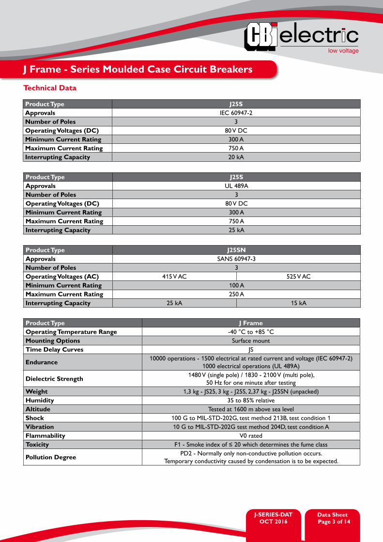
Product Type J25SApprovals IEC 60947-2Number of Poles 3Operating Voltages (DC) 80 V DCMinimum Current Rating 300 AMaximum Current Rating 750 AInterrupting Capacity 20 kA
Product Type J25SApprovals UL 489ANumber of Poles 3Operating Voltages (DC) 80 V DCMinimum Current Rating 300 AMaximum Current Rating 750 AInterrupting Capacity 25 kA
Product Type J25SNApprovals SANS 60947-3Number of Poles 3Operating Voltages (AC) 415 V AC 525 V ACMinimum Current Rating 100 AMaximum Current Rating 250 AInterrupting Capacity 25 kA 15 kA
Product Type J FrameOperating Temperature Range -40 °C to +85 °CMounting Options Surface mount Time Delay Curves JS
Endurance 10000 operations - 1500 electrical at rated current and voltage (IEC 60947-2)1000 electrical operations (UL 489A)
Dielectric Strength 1480 V (single pole) / 1830 - 2100 V (multi pole), 50 Hz for one minute after testing
Weight 1,3 kg - JS25, 3 kg - J25S, 2,37 kg - J25SN (unpacked)Humidity 35 to 85% relativeAltitude Tested at 1600 m above sea levelShock 100 G to MIL-STD-202G, test method 213B, test condition 1Vibration 10 G to MIL-STD-202G test method 204D, test condition AFlammability V0 ratedToxicity F1 - Smoke index of ≤ 20 which determines the fume class
Pollution Degree PD2 - Normally only non-conductive pollution occurs. Temporary conductivity caused by condensation is to be expected.

J-SERIES-DATOCT 2016
Data SheetPage
low voltage
4 of 14
J Frame - Series Moulded Case Circuit Breakers
Ordering Information
Example Code 1: JSS0125Group 1 2Requirement JS25 Frame 125 AOrder Number JSS0 125
Type Barriers Poles TerminalskA @
Rating (A) Order No.240 V 415 V 525 V
Distribution Circuit Breakers (Mixed Load)
JS25 1G1 25 - -
80, 100 JSS0_ _ _125 JSS0125
G4B 25 - -150 JSS0150200 JSS0200
J25S 4 3
G1 - 25 15
250 JSO025020, 30, 40, 50, 60 JSO0_ _ _
80, 100 JSO0_ _ _125 JSO0125150 JSO0150
G4B - 25 15160, 175, 200 JSO0_ _ _
225 JSO0225250 JSO0250
Switch Disconnector
J25SN 3 3G1 - 25++ 15++
100 JSN0100150 JSN0150
G4B - 25++ 15++200 JSN0200250 JSN0250
For options not listed, please contact CBI
JS Accessories Ordering Information
Description Comments Order Number
Shunt Trip110 - 250 V AC380 - 600 V AC
24 V DC
FSAA002FSAA003FSAA001
Undervoltage Release 220 - 250 V AC380 - 440 V AC
FSAC220FSAC380
Auxiliary Switch FSAH002Trip Alarm Switch FSAF001Auxiliary + Trip Alarm Switch Combo FSAV001Handle Lock FSAP001G4B Stub Busbar (500 - 600 A) 3 per set for line or load side FSAX001G5 Tandem Box Terminal (250 A max.) 3 per set for line or load side FSAX002Daros Rotary Handle 4470076Phase Barriers Set of 2 FSAX004Terminal Covers (Each) (Line or Load) FSAX005

low voltage
J-SERIES-DATOCT 2016
Data SheetPage 5 of 14
Time Delay Curves
Tri
ppin
g T
ime
% Rated Current
Minimum
Maximum
MIN
UT
ES
SEC
ON
DS
* The published time delay curves are generated at 30oC ambient temperature with the Circuit Breaker mounted in the up-right position. The “must hold”, “must trip” and “instantaneous trip” current values are not affected by temperature, although delay time for the other operating current values may have to be adjusted using the temperature compensation curve which is available on request.
J Frame - Series Moulded Case Circuit Breakers

J-SERIES-DATOCT 2016
Data SheetPage
low voltage
6 of 14
Time Delay Curves
Tri
ppin
g T
ime
% Rated Current
Minimum
Maximum
MIN
UT
ES
SEC
ON
DS
* The published time delay curves are generated at 30oC ambient temperature with the Circuit Breaker mounted in the up-right position. The “must hold”, “must trip” and “instantaneous trip” current values are not affected by temperature, although delay time for the other operating current values may have to be adjusted using the temperature compensation curve which is available on request.
J Frame - Series Moulded Case Circuit Breakers
low voltage
J-SERIES-DATOCT 2016
Data SheetPage 7 of 14
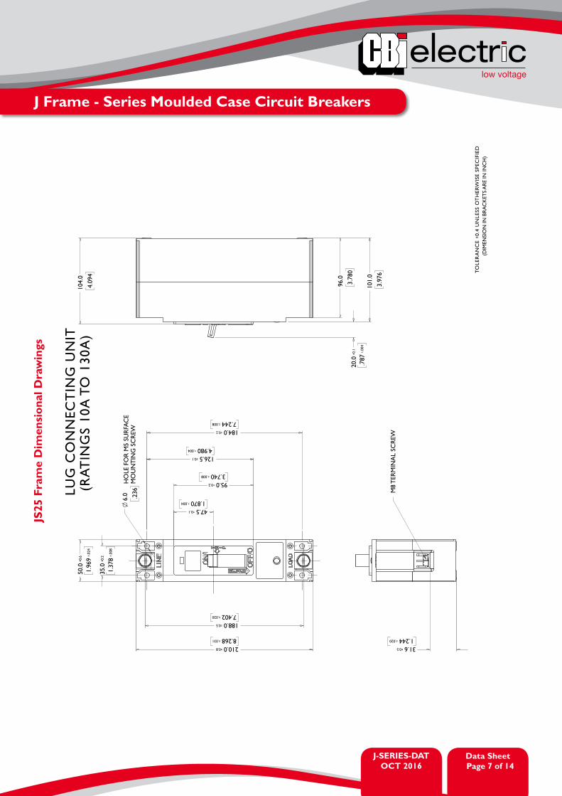
J Frame - Series Moulded Case Circuit Breakers
JS25
Fra
me
Dim
ensi
onal
Dra
win
gs

J-SERIES-DATOCT 2016
Data SheetPage
low voltage
8 of 14
J Frame - Series Moulded Case Circuit Breakers
JS25
Fra
me
Dim
ensi
onal
Dra
win
gs

low voltage
J-SERIES-DATOCT 2016
Data SheetPage 9 of 14
J Frame - Series Moulded Case Circuit Breakers
JS25
Fra
me
Dim
ensi
onal
Dra
win
gs

J-SERIES-DATOCT 2016
Data SheetPage
low voltage
10 of 14
J Frame - Series Moulded Case Circuit Breakers
JS25
Fra
me
Dim
ensi
onal
Dra
win
gs

low voltage
J-SERIES-DATOCT 2016
Data SheetPage 11 of 14
J Frame - Series Moulded Case Circuit Breakers
J25S
Fra
me
Dim
ensi
onal
Dra
win
gs
J-SERIES-DATOCT 2016
Data SheetPage
low voltage
12 of 14
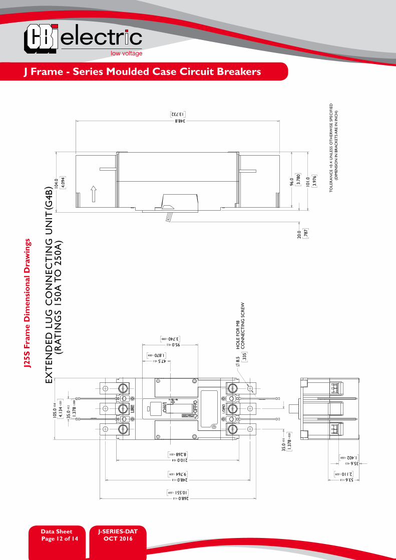
J Frame - Series Moulded Case Circuit Breakers
J25S
Fra
me
Dim
ensi
onal
Dra
win
gs

low voltage
J-SERIES-DATOCT 2016
Data SheetPage 13 of 14
J Frame - Series Moulded Case Circuit Breakers
J25S
Fra
me
Dim
ensi
onal
Dra
win
gs

A member of the Group
AUSTRALIACBI-electric: Australia90 Fairbank Road Clayton SouthMelbourne Victoria 3169 AustraliaTel: +61 3 9590 3500Fax: +61 3 9551 1051Email: [email protected]: www.cbi-electric.com.au
SOUTH AFRICACBI-electric: low voltageTripswitch Drive ElandsfonteinGauteng South AfricaTel: +27 11 928 2000Fax: + 27 11 392 2354Email: [email protected]: www.cbi-lowvoltage.co.za
USACBI-electric: North America35 E. Uwchlan Ave Suite 328Exton PA 19341 USATel: +1 610 524 9949Fax: +1 610 524 9945E-mail: [email protected]: www.cbibreakers.com
J-SERIES-DATOCT 2016
Data SheetPage 13 of 13
Please review our Customer Terms and Conditions on www.cbi-lowvoltage.co.zaAll rights reserved. Unless otherwise indicated, all materials on these pages are copyrighted by CBI (Pty) Ltd. No part of these pages, either text or image may be used for any purpose other than personal use. Therefore, reproduction, modification, storage in a retrieval system or retransmission, in any form or by any means, electronic, mechanical or otherwise, for reasons other than personal use, is strictly prohibited without prior written permission. CBI (Pty) Ltd reserves the right to alter any details of this document without notice and while every effort is made to ensure the accuracy of the content, no warranty is given as to accuracy of this document and no responsibility will be accepted for error or misinterpretation and any resulting loss.
low voltage
Data SheetPage 14 of 14
J Frame - Series Moulded Case Circuit Breakers
J25S
Fra
me
Dim
ensi
onal
Dra
win
gs