jacobs exhaust brake - jacobs vehicle systems e brake by jacobs for dodge ram installation manual 1...
TRANSCRIPT
CUMMINS E BRAKE BY JACOBS FOR DODGE RAM INSTALLATION MANUAL 106-03-2005 K6859713
InstallationManual
For 2003 through 2006 Dodge Ram TrucksEquipped with the Cummins ISB 5.9 Engine
Jacobs Exhaust Brake®
Please see Web Site for latest instructions
www.jakebrake.com

2 CUMMINS E BRAKE BY JACOBS FOR DODGE RAM INSTALLATION MANUAL06-03-2005 K6859713
Table of ContentsSection 1: Preparation .................................................... 3
Section 2: Installing the Exhaust Brake ........................... 7
Section 3: Installing the Pneumatic Group ....................... 9
Section 4: Installing the Vacuum System ......................11
Section 5: Installing the Wiring Harnesses .....................13
Section 6: Installing the Vacuum Supply Hose ...............17
Section 7: Installing the Brake Switch ...........................18
Section 8: Installing the ECM Connection ......................20
Section 9: Completing the Installation ...........................21
Section 10: Operational Check .....................................22
Section 11: Exhaust Brake Features .............................23
Section 12: Troubleshooting .........................................24
IntroductionThe procedures for installing the brake system areorganized into twelve main sections, with each sectiondetailing the installation of related components. Westrongly recommend that you perform the procedures inthe order in which they are presented. The last section liststroubleshooting procedures, in case you are experiencingproblems with the Jacobs Exhaust Brake®.
Safety PrecautionsThe following symbols in this manual signalconditions potentially dangerous to the mechanic orequipment. Read this manual carefully. Know whenthese conditions can exist. Then take necessarysteps to protect personnel as well as equipment.
THIS SYMBOL WARNS OF POSSIBLEPERSONAL INJURY.
THIS SYMBOL REFERS TO POSSIBLEEQUIPMENT DAMAGE.
NOTE: INDICATES AN OPERATION, PROCEDURE ORINSTRUCTION THAT IS IMPORTANT FOR CORRECTSERVICE.
Fuels, electrical equipment, exhaust gases andmoving engine parts present potential hazards thatcould result in personal injury. Take care wheninstalling equipment or parts. Always wear safetyglasses. Always use correct tools and follow properprocedures as outlined in this manual.
For additional information or technical support, contactCummins Customer Assistance Center by calling 1-800-DIESELS (1-800-343-7357).
Application NotesThe Jacobs Exhaust Brake kit has been specificallyengineered to fit your Dodge Ram truck equipped with theCummins ISB engine All parts are included in the kit,allowing installation without requiring any fabrication.
Special Tools andMaterials RequiredYou should have the following tools and materials beforeyou begin this installation:
• Rust penetrant, such as Liquid Wrench®
• Battery terminal puller
• Common hand tools such as metric wrenches,screwdrivers and pliers.
• Torque wrenches
• Drill with a ¼” bit and a #27 drill bit
• #56 (3/64") Drill bit or back probe tool (mopar), orpaper clip to remove ECM sealing plugs
• Knife or other tool for cutting the rubber vacuum hose
• Clean shop towels
• Teflon® pipe sealant
• Loctite® 242 or equivalent
• Volt/Ohm Meter or test light
• 4 mm Ball End Hex Driver or Hex Wrench
• Electrical Tape
• Heat Gun
• Dielectric Grease
• Miller Connector Tool #6680 (or very small thin bladedscrewdriver)
NOTE: IF YOU HAVE A VEHICLE WITHOUT AIR CONDITIONING,YOU WILL NEED TO PURCHASE A DIFFERENTACCESSORY DRIVE BELT CUMMINS PART NUMBER4025090 (LENGTH WILL BE 2,892 MM/113.9 IN).
Application GuideModel Transmission Mopar CumminsYear Part Number Part Number2003 Manual N/A 40894272003 Automatic N/A N/A2004 Manual N/A 40894272004 Automatic N/A N/A2004.5 Manual 822008835AB 40899242004.5 Automatic N/A N/A2005 Manual 822008835AB 40899242005 Automatic N/A N/A2006 Manual 822009823 40899242006 Automatic 822009823 4089924

CUMMINS E BRAKE BY JACOBS FOR DODGE RAM INSTALLATION MANUAL 306-03-2005 K6859713
Section 1: Preparation
Fig. 3a
Fig. 3b
Fig. 3c
NOTE: WITH THE BATTERIES CONNECTED,DISCONNECTING THE VEHICLE POWERCONNECTOR CONTAINING KEY SWITCHEDPOWER WILL RESULT IN FAULT CODES BEINGRECORDED IN THE VEHICLE ECM AND ABSMODULE. TO PREVENT THIS, SWITCHED 12 VOLTPOWER NEEDS TO BE FOUND WITHOUTDISCONNECTING THE VISTRONIC FANCONNECTORS.
1. Locating key switched power.
For MY2003 vehiclesFor MY2003 vehiclesFor MY2003 vehiclesFor MY2003 vehiclesFor MY2003 vehicles
a. Locate the Vistronic fan connector, located on the topside of the dash panel in the passenger side corner.(see figure 3a)
b. Locate the Solid Dark Blue wire in the right sideconnector pin 13. This should be 12 volt key switchedpower. Check this pin with a volt/ohm meter or testlight with a hard point test lead, back probe tool orpaper clip. (see figure 3b)
c. It should read 12 Volts with the key in the on positionand no voltage when the key is off. If pin 13 does nothave key switched power, test the other pins. Whenyou have found the key switch power use this pin andwire in place of the Solid Dark Blue wire. (see figure 3c)
d. Record the color of the wire and the pin number thatyou have found to have 12 volt switched power.
Wire Color: ______________________________________
Pin Number:______________________________________

4 CUMMINS E BRAKE BY JACOBS FOR DODGE RAM INSTALLATION MANUAL06-03-2005 K6859713
NOTE: WITH THE BATTERIES CONNECTED,DISCONNECTING THE VEHICLE POWERCONNECTOR CONTAINING KEY SWITCHEDPOWER WILL RESULT IN FAULT CODES BEINGRECORDED IN THE VEHICLE ECM AND ABSMODULE. TO PREVENT THIS, SWITCHED 12 VOLTPOWER NEEDS TO BE FOUND WITHOUTDISCONNECTING THE VISTRONIC FANCONNECTORS.
For MY2004 and MY2004.5 vehicles
a. Locate the two 24-pin connectors. They are located onthe top side of the dash panel on the driver's side. Theleft connector is gray, the right connector black. Keyswitched power is in the black connector (see figure 4a)
b. Locate the Pink w/Gray Stripe wire in the blackconnector, pin location B4. This should be 12 volt keyswitched power. Check this pin with a volt/ohm meteror test light with a hard point test lead, back probetool or paper clip. (see figure 4b)
c. It should read 12 Volts with the key in the on positionand no voltage when the key is off. If pin B4 does nothave key switched power, test the other pins. Whenyou have found the key switch power use this pin andwire in place of the Pink with gray stripe wire. (seefigure 4d)
d. Record the color of the wire and the pin number thatyou have found to have 12 volt switched power.
Wire Color: ______________________________________
Pin Number:______________________________________
For MY2005 vehicles
a. Locate the two 34-pin connectors located on the topside of the dash panel on the driver's side. The leftconnector is gray, the right connector black. Keyswitched power is in the black connector (see figure 4c)
b. Locate the Pink w/Gray Stripe wire in the blackconnector, pin location (MY2005 pin 13). This shouldbe 12 volt key switched power. Check this pin with avolt/ohm meter or test light with a hard point test lead,back probe tool or paper clip. (see figure 5B)
c. It should read 12 Volts with the key in the on positionand no voltage when the key is off. If the pin (MY2005pin 13) does not have key switched power, test theother pins. When you have found the key switch poweruse this pin and wire in place of the Pink with graystripe wire. (see figure 4d)
d. Record the color of the wire and the pin number thatyou have found to have 12 volt switched power.
Wire Color:_______________________________________
Pin Number:______________________________________
Fig. 4a
Fig. 4b
Fig. 4d
Fig. 4c

CUMMINS E BRAKE BY JACOBS FOR DODGE RAM INSTALLATION MANUAL 506-03-2005 K6859713
For MY2006 vehicles
a. Power will be take from the TIPM module which islocate in front of the drivers side battery (see figure 5a)
b. Release the mounting tabs located on each side of theTIPM to release the whole assembly allowing it to belifted/tilted up exposing the wire harness's (see figures5b and 5c)
c. Locate connector "G". Locate the Grey wire with pinkstripe in cavity 14.(see figure 5d )
d. The pin should read 12 Volts with the key in the onposition and no voltage when the key is off. If the pindoes not have key switched power, test the other pins.When you have found the key switch power use this pinand wire in place of the Grey with pink stripe wire.
e. Record the color of the wire and the pin number thatyou have found to have 12 volt switched power.
Wire Color:_______________________________________
Pin Number:______________________________________
Fig. 5c
Fig. 5a
Fig. 5b
Fig. 5d

6 CUMMINS E BRAKE BY JACOBS FOR DODGE RAM INSTALLATION MANUAL06-03-2005 K6859713
2. Disconnecting Batteries.
NOTE: WHEN YOU DISCONNECT THE BATTERIES, THEMEMORY OF THE CLOCK WILL BE LOST.
a. Use a battery terminal puller to disconnect the negative(-) leads from both batteries. (see figure 6a)
b. Use a battery terminal puller to disconnect the positive(+) leads from both batteries. (see figure 6a)
c. Loosen and remove the clamps that hold the batteriesfirmly in the battery trays. (see figure 6a)
d. Remove the batteries from both sides of the vehicle.
3. Removing front wheel wells.
NOTE: To allow for ease in installation of the exhaustbrake assembly and gain access to ECM it is requiredthat both front wheel wells be removed to gain access.
a. To facilitate removal of the front tires and wheel wells,use a floor jack or lift to elevate the front axle.
MAKE SURE TO SUPPORT THEVEHICLE PROPERLY (JACK STANDS)AS YOU WILL BE WORKING UNDER IT.
b. Remove both front tires. (see figure 6b)
c. Remove the front wheel wells by loosening andremoving the eight (8) capscrews attaching the wellto the truck fender. Pull the wheel well down to exposethe ABS cable. Remove the ABS cable from the wheelwells and set the wheel wells aside. (see figure 6c and6d)
Fig. 6b
Fig. 6c
Fig. 6d
Fig. 6a

CUMMINS E BRAKE BY JACOBS FOR DODGE RAM INSTALLATION MANUAL 706-03-2005 K6859713
1. Remove the existing Exhaust Elbow that mounts tothe rear of the Turbocharger. (see figure 7a and 7b)
a. Loosen (11 mm socket) the “V” clamp that attaches theexhaust pipe to the exit side of the elbow. Slide the “V”clamp over the exhaust pipe away from the elbow. Anew clamp is provided in the kit. (See figure 7b)
b. Loosen (10 mm socket) and remove the “V” clamp thatattaches the elbow to the exhaust side of theturbocharger. A new clamp is provided in the kit. (Seefigure 7b)
c. Push the exhuast pipe backwards away from the turbooutlet; Do not loosen the bolts holding the exhaust pipeto the transmission housing. This bracket will helpsupport the brake during installation. Slide the elbowtoward the rear of the vehicle. This will allow the twopins in the turbo to come free. Remove the elbow fromthe vehicle. This elbow can be reused if the exhaustbrake is removed.
2. Attach the Exhaust Brake Assembly to theTurbocharger.
The brake needs to be oriented in a certainway to fit easily in place.
a. Clean the gasket surfaces of the turbo outlet and theexhaust brake assembly, making sure the surfaces arefree of dirt, grease and oil.
b. Mark the location of the holes on the turbo outlet flangeon the edge of the flange Using a grease pencil. Markthe location of the pins on the edge of the exhaustbrake. This will aid in aligning the brake later in theinstall.
c. Place the entire outlet flange of the brake into theexhaust pipe. Reference pictures on page 8.
d. Push the brake back toward engine until actuator clearsthe air conditioning condensor.
e. Rotate brake upwards. Then lift the brake and slideoutlet pilot into exhaust pipe.
f. Slide the "V" clamp Part number 4920021 onto thebrake’s exhaust inlet flange. Push the clamp up ontothe exhaust brake inlet flange so it is out of the way.
g. Remove the wax paper from the back of the gasket.Attach it to the exhaust brake flange side, sliding thegasket over the pins and firmly pressing it in place.
BE CAREFUL NOT TO DAMAGE THEGASKET BY HITTING IT WHENINSTALLING THE EXHAUST BRAKE.
h. Have someone push on exhaust tail pipe until brake isclose to the turbo. Line up lines on the turbo outlet andbrake inlet. The pins should slide into the holes in theturbo.
i. Slide the "V" clamp into place. Tighten the clamp enoughto hold the brake flush with the turbocharger outlet.
Section 2: Installing the Exhaust Brake
Fig. 7a
Fig. 7b
Fig. 7c
Torque (10mm socket) the “V” clamp.
Torque Value: 8.5 N·m (75 in-lb)
j. Tighten the Jam nut on "V" Clamp holding the first nutwith a wrench.
Jam Nut Torque: 11.3 N·m (100 in-lb)
3. Attach the exhaust pipe to the exhaust brakeassembly. (see figure 7c)
a. Have someone push on the exhaust pipe tip at theback of the vehicle. They may have to rotate the pipeslightly to align the pipe with the brake. Once the pipe isaligned properly to the brake slide the "V"clamp intoplace.

8 CUMMINS E BRAKE BY JACOBS FOR DODGE RAM INSTALLATION MANUAL06-03-2005 K6859713
1 2
3 4
5 6
b. Tighten the clamp enough to hold the exhaust pipeflush with the brake outlet.
c. Torque (11 mm socket) the “V” clamp between thebrake and exhaust pipe.
Torque Value: 11.3 N·m (100 in-lb)
Pictures showing how to get brake into place
Place entire outlet flange into exhuast pipe
Rotate Actuator Canister upward Move brake into alignment
Push brake toward the engine
Rotate Brake upwards sliding end into exhaustpipe
Rotate Brake upwards
d. Tighten the Jam nut on "V" Clamp holding the first nutwith a wrench.
Jam Nut Torque: 11.3 N·m (100 in-lb)

CUMMINS E BRAKE BY JACOBS FOR DODGE RAM INSTALLATION MANUAL 906-03-2005 K6859713
1. Drill Vacuum Solenoid Mounting Holes.
NOTE: THE VACUUM SOLENOID WILL MOUNT ON THEBACK (REAR FACE) OF THE PASSENGER SIDEBATTERY TRAY.
a. Take the brass inserts out of the isolators. Install theisolators into the bracket as shown in figure 9a.
b. Reinstall the inserts as shown in figure 9a.
c. Using the solenoid mounting bracket as a template, laythe bracket on the inside rear face of the battery trayand mark the two (2) drill holes. For location seefigure's 9b & 9c.
d. Using a ¼” drill bit, drill the two mounting holes throughthe battery tray.
2. Using the ¼” drill bit, drill the hole to be used formounting the P-clip. For location see figures 9band 9c.
3. Prepare the Solenoid/Bracket for Mounting.
NOTE: USE PIPE SEALANT ON ALL NPT (PIPE THREAD)CONNECTIONS.
a. Attach the 90o hose fitting to the solenoid’s #1 port.Be sure to orient the outlet of the 90o fitting pointingaway from the solenoid’s coil.
b. Attach the straight hose fitting to the solenoid’s #2port.
c. Using Loctite® on the screw threads, attach thesolenoid to the mounting bracket with the two #8-20screws and lock washers supplied in the kit.
4. Mount the Solenoid/Bracket Assembly.
a. Place a flat washer on each of the two M6 x 32 mmcapscrews. Slide the capscrews through the holes inthe battery box so the threads are outside the batterybox.
NOTE: THE HEADS OF THE CAPSCREWS SHOULD BEINSIDE THE BATTERY BOX TO PREVENT DAMAGETO THE BATTERY AND/OR BATTERY BLANKET.
b. Place the solenoid and bracket onto the capscrews sothat the black coil is down. (See figure 9d)
c. Place two additional flat washers on the capscrews andinstall locking nuts.
Section 3: Installing the Pneumatic Group
Fig. 9a
Fig. 9b
Fig. 9c
Fig. 9d

10 CUMMINS E BRAKE BY JACOBS FOR DODGE RAM INSTALLATION MANUAL06-03-2005 K6859713
5. Connect the Exhaust Brake Vacuum Actuator to theSolenoid
a. Using a hose clamp and ¼ inch I.D. hose supplied in thekit, connect one end of the hose to the vacuum tube onthe exhaust brake’s vacuum actuator. Tighten the hoseclamp.
b. Install p-clip supplied in the kit onto the hose. Route theend of the hose from the actuator to the end of thebattery tray. Loosely mount the p-clip to the batterytray using the M6 X 19 mm capscrew, flat washer andlock nut provided in the kit. (see figures 10a and 10b).The head of the capscrew should be inside battery trayas shown in figure 10b.
c. Route the end of the hose to the solenoid’s #2 port(straight fitting) as shown in figure 10b.
d. Trim the hose to length and attach the hose to thesolenoid’s #2 port fitting. No clamp is required for thisend. (see figure 10b)
e. Tighten p-clip capscrew and nut.
Fig. 10a
Fig. 10b

CUMMINS E BRAKE BY JACOBS FOR DODGE RAM INSTALLATION MANUAL 1106-03-2005 K6859713
THE VACUUM PUMP MUST NEVER BERUN WITHOUT A VACUUM LOAD (I.E.OPEN TO ATMOSPHERE). IF THE
PUMP IS RUN WITH NO LOAD, THE PUMPDIAPHRAGM WILL FAIL. IF THE VEHICLE MUST BEDRIVEN AFTER INSTALLING THE VACUUM PUMPBUT BEFORE INSTALLING THE EXHAUST BRAKEASSEMBLY, CONNECT THE PUMP TO THEVACUUM SOLENOID BEFORE RUNNING THEENGINE (AS SHOWN IN THE INSTALLATIONMANUAL). THE SOLENOID MUST REMAIN OFF(DE-ENERGIZED) UNTIL THE SOLENOID ISCONNECTED TO THE EXHAUST BRAKE. ANALTERNATIVE METHOD IS TO SECURELY(RE)INSTALL THE RED PLASTIC VACUUM OUTLETCAP SHIPPED ON THE PUMP. THIS CAP ISDESIGNED TO PROVIDE SUFFICIENT VACUUMLOAD.
VACUUM PUMP FAILURE DUE TO PARTIALSYSTEM INSTALLS AND RUNNING THE PUMPWITHOUT VACUUM LOAD IS NOT COVERED BYBRAKE WARRANTY.
1. Gaining access to gear housing.
For 2003 model vehicles, unfasten the three capscrewson top of the Throttle Position Sensor assembly.Relocate the Throttle Position Sensor assembly to gainaccess to the top of the gear housing. (see figure 11a)
2. Prepare the Vacuum Pump/Bracket for mounting.
a. Attach the vacuum pump to the mounting bracketusing the three M8 x 30 mm capscrews supplied in thevacuum kit. (See figure 11b)
Torque to 25 N.m (18 ft-lb).
b. Install 3/8” I.D. hose onto the vacuum pump and securewith the hose clamp provided.
3. Mount the Vacuum Pump/Bracket Assembly.
a. Attach the vacuum pump/bracket assembly to the rearof the gear housing using the four M8 x 45mmcapscrews supplied in the vacuum kit. Reference gearhousing holes in figure 11c and installed vacuum pumpin figure 11d.
Torque to 25 N.m (18 ft-lb).
b. Insure no wiring harnesses are taut against the vacuumpump bracket. This is to avoid harness chafing.
NOTE: IT MAY BE NECESSARY TO REMOVE THEACCESSORY DRIVE BELT TO EASE INSTALLATION
Fig. 11a
Fig. 11b
Fig. 11c
Fig. 11d
Section 4: Installing the Vacuum System
12 CUMMINS E BRAKE BY JACOBS FOR DODGE RAM INSTALLATION MANUAL06-03-2005 K6859713
Fig. 12a
Fig. 12b
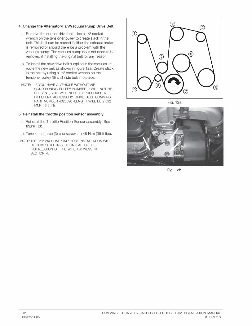
4. Change the Alternator/Fan/Vacuum Pump Drive Belt.
a. Remove the current drive belt. Use a 1/2 socketwrench on the tensioner pulley to create slack in thebelt. This belt can be reused if either the exhaust brakeis removed or should there be a problem with thevacuum pump. The vacuum pump does not need to beremoved if installing the original belt for any reason.
b. To install the new drive belt supplied in the vacuum kit,route the new belt as shown in figure 12a. Create slackin the belt by using a 1/2 socket wrench on thetensioner pulley (8) and slide belt into place.
NOTE: IF YOU HAVE A VEHICLE WITHOUT AIRCONDITIONING PULLEY NUMBER 9 WILL NOT BEPRESENT, YOU WILL NEED TO PURCHASE ADIFFERENT ACCESSORY DRIVE BELT CUMMINSPART NUMBER 4025090 (LENGTH WILL BE 2,892MM/113.9 IN).
5. Reinstall the throttle position sensor assembly
a. Reinstall the Throttle Position Sensor assembly. Seefigure 12b.
b. Torque the three (3) cap screws to 48 N.m (35 ft lbs).
NOTE: THE 3/8" VACUUM PUMP HOSE INSTALLATION WILLBE COMPLETED IN SECTION 5 AFTER THEINSTALLATION OF THE WIRE HARNESS INSECTION 4.

CUMMINS E BRAKE BY JACOBS FOR DODGE RAM INSTALLATION MANUAL 1306-03-2005 K6859713
Harness Installation for MY2003 through MY2006Vehicles.
1. Route the Harness.
For MY2003 ( for 2004-2006 go to step e)
a. Remove wire harness from the convolute.
b. Open the vehicle's wiring "trough" located along the topof the engine compartment plenum.
c. Route the harness through the trough.
d. Skip to step f.
e. Lay the exhaust brake harness near the top of the dashpanel in the engine compartment over the engine.
f. The harness should be oriented so that the end with therelay is located on the passenger side of the enginecompartment and the end with the fuse-holder islocated on the driver side of the engine compartment.(See figure 13a)
g. If needed, reroute the brake harness under the vehicleharness running along the top of the dash panel. It isrecommended that the driver’s end of the harness berouted behind the two 24-pin connectors and themaster brake cylinder. (see figure 13b)
h. Using provided tie-wraps, secure the harness under thevehicle harness running along the top of the dash panel.To allow for minor adjustments to the location of theharness, it is recommended the tie-wraps looselysecure the brake harness until all hookups arecompleted.
2. Mount the Harness Relay.
Remove the nut from the dash panel stud (see figure28). Put the relay bracket over the stud. Put theharness black and green/yellow ground wire eyeletonto the stud and replace the nut on the dash panelstud. Tighten nut.
For 2005 and 2006 vehicles a sheet metal screwshould be used to attact the relay braket and theground wire lug. Use a #27 Drill to drill a hole where thestud is pictured in figure 13c. Use the sheet metalscrew provided to attach the solenoid and ground lug.
3. Attach the Solenoid Connector.
Attach the male connector with the purple (or blue) andblack wires from the harness to the female connectorwith the two black wires on the exhaust brake solenoid.
Section 5: Installing the Wiring Harness
Fig. 13a
Fig. 13c
Fig. 13b

14 CUMMINS E BRAKE BY JACOBS FOR DODGE RAM INSTALLATION MANUAL06-03-2005 K6859713
Fig. 14c
Fig. 14b
4. Connect the Harness to the Switched 12 volt powersupply.
For Model Years 2003 - 2005
a. Route the exposed solid grey wire on the driver’s sidefrom behind the 24-pin (34-pin for MY 2005)connectors to the black connector on the right. (seefigure 14a)
b. Disconnect the black 24-pin (34-pin for MY 2005)connector.
c. Locate the switched 12 volt power wire called out onpage 4, step 1d.
NOTE: IT IS RECOMMENDED THAT THE SWITCHEDPOWER LEAD NOT BE CUT. THE SPLICE SHOULDBE SOLDERED TO THE EXISTING UNCUT WIRE.
d. Strip electrical tape from the connector’s harness asneeded. Approximately 3 inches from the end of thepin, strip ½ inch of insulation from the switched 12 voltwire to prepare the wire for splicing. Take care to notdamage the wire strands. (see figure 14c)
e. Center splice the solid grey wire from the exhaust brakeharness to the switched 12 volt connector wire. (seefigure 14c)
f. Tape the exposed wire with electrical tape.
Center splicing procedure:
1. Strip ½ inch of insulation from the wire to be spliced. Becareful not to damage the strands of the wire.
2. Separate the strands into two sections as ahown in thefigure 14a.
3. Insert the second wire into the opening and wrap thewire around to join the two wires together.
4. Solder the joint using a non-acid core solder.
5. Seal the joint by wrapping it with electrical tape.
Fig. 14a

CUMMINS E BRAKE BY JACOBS FOR DODGE RAM INSTALLATION MANUAL 1506-03-2005 K6859713
For Model Year 2006
a. Route the exhaust brake harness's Grey wire with theconvolute around the battery and over to TIPMmodule. (see figure 15a)
NOTE: IT IS RECOMMENDED THAT THE SWITCHEDPOWER LEAD NOT BE CUT. THE SPLICE SHOULDBE SOLDERED TO THE EXISTING UNCUT WIRE.
b. Center splice the exhaust brake harness's grey wire tothe Grey wire with pink stripe in the G connector, cavity14 or where 12 volt switch power was found on page5. (see figure 14c)
NOTE: IF THE BRAKE HARNESS GREY WIRE IS NOT LONGENOUGH, SOLDER A 16-GAUGE EXTENSION WIREONTO THE HARNESS AND COVER THEEXTENSION WITH 1/4" DIAMETER PLASTICCONVOLUTE AND ELECTRICAL TAPE.
c. Tape and secure the exhaust brake harness's grey wireto the G connectors wiring bundle with electrical tapeand a tie wrap.(see figures 15b, 15c, 15d, and 15e)
d. Secure the convolute tubing containing the grey wire tothe exisiting hosing to prevent movement.
Fig. 15a
Fig. 15b Fig. 15c
Fig. 15d Fig. 15e
16 CUMMINS E BRAKE BY JACOBS FOR DODGE RAM INSTALLATION MANUAL06-03-2005 K6859713
Fig. 16a
Fig. 16b
Fig. 16c
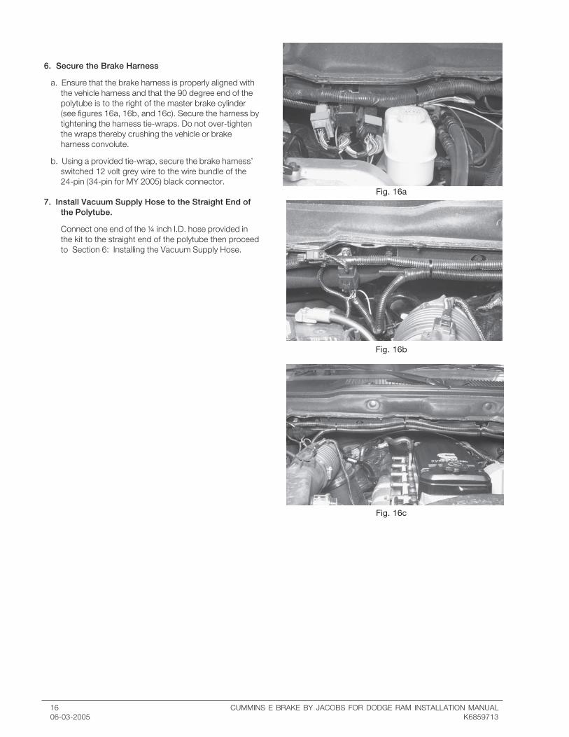
6. Secure the Brake Harness
a. Ensure that the brake harness is properly aligned withthe vehicle harness and that the 90 degree end of thepolytube is to the right of the master brake cylinder(see figures 16a, 16b, and 16c). Secure the harness bytightening the harness tie-wraps. Do not over-tightenthe wraps thereby crushing the vehicle or brakeharness convolute.
b. Using a provided tie-wrap, secure the brake harness’switched 12 volt grey wire to the wire bundle of the24-pin (34-pin for MY 2005) black connector.
7. Install Vacuum Supply Hose to the Straight End ofthe Polytube.
Connect one end of the ¼ inch I.D. hose provided inthe kit to the straight end of the polytube then proceedto Section 6: Installing the Vacuum Supply Hose.

CUMMINS E BRAKE BY JACOBS FOR DODGE RAM INSTALLATION MANUAL 1706-03-2005 K6859713
Section 6: Installing the Vacuum Supply Hose
Fig. 17a
Fig. 17b
1. Install vacuum tube to exhaust brake solenoid
a. Route the ¼ inch I.D hose to the 90o elbow onsolenoid port #1. (see figure 17a)
b. Trim the hose to size and attach the hose to thesolenoid’s #1 port fitting. No hose clamp is required.
c. Using provided tie-wraps, secure the hose from chafingand heat sources taking care to not crimp or pinch thehose closed.
2. Attach the Vacuum Pump to the poly tubing.
a. Route the 3/8 inch I.D. hose from the vacuum pump tothe 90o polytube fitting on the drivers side. (see figure17b)
b. Cut the hose to length and connect the 3/8 inch I.D.hose to the 90o polytube fitting.
c. Using provided tie-wraps, secure the hose from chafingand heat sources taking care to not crimp or pinch thehose closed.

18 CUMMINS E BRAKE BY JACOBS FOR DODGE RAM INSTALLATION MANUAL06-03-2005 K6859713
Fig. 18a
Fig. 18b
Fig. 18c
Fig. 18eFig. 18d
Section 7: Installing the Brake Switch
For MY2003 through MY2006 Manual TransmissionVehicles
1. Run the wires under the dash panel then towards thedriver side as shown in figure 18a.
2. Locate the grommet in the floor panel behind thepedals as shown in figure 18b. With a small screwdrivermake a hole in the grommet to slide the wiring harnessthrough.
3. Slide the wires through the grommet. Pull back thecarpet on the drivers side and route the harness justunder the top of the carpet. Restore the carpet to itsoriginal position. (see figure 18c)
4. Attach the stalk switch to the shifter stalk and installthe four (4) clamping screws through the attachmentpiece. Two bushings provided with the switch will notbe used in this installation and may be discarded. (seefigure 18d)
5. Using tie wraps provided in the kit, secure the switchwires to the shifter stalk.
6. In the engine compartment route the three wires alongthe vehicle harness, from the grommet to the brakeharness on the drivers side. (see figure 18e)

CUMMINS E BRAKE BY JACOBS FOR DODGE RAM INSTALLATION MANUAL 1906-03-2005 K6859713
For MY2006 Automatic Transmission Vehicles
1. Remove the dash cover just below the steer column asshown in figure 19a.
2. Run the wires though the space between the dashpanel and the steering column as shown in figures 19b& 19c.
3. Locate the grommet in the floor panel behind thepedals as shown in figure 19e. For automatictransmissions there is a cable going through thegromment. With a small screwdriver make a hole in thegrommet to the slide of the existing cable to slide thewiring harness through.
4. Slide the wires through the grommet. (see figure 19e)
5. Install the two bushings into the switch housing andattachment piece. Attach the stalk switch to the shifterstalk and install the four (4) clamping screws throughthe attachment piece. (see figure 19d)
6. Using tie wraps provided in the kit, secure the switchwires to the shifter stalk and to the automatictransmission cable (see figure 19e).
7. Replace the dash cover.
8. In the engine compartment route the three wires alongthe vehicle harness, from the grommet to the brakeharness on the drivers side. (see figure 19f)
Fig. 19a
Fig. 19b
Fig. 19e Fig. 19f
Fig. 19c Fig. 19d
20 CUMMINS E BRAKE BY JACOBS FOR DODGE RAM INSTALLATION MANUAL06-03-2005 K6859713
Section 8: Installing the ECM Connections
Fig. 20a
Fig. 20b
Fig. 20c
Fig. 20d
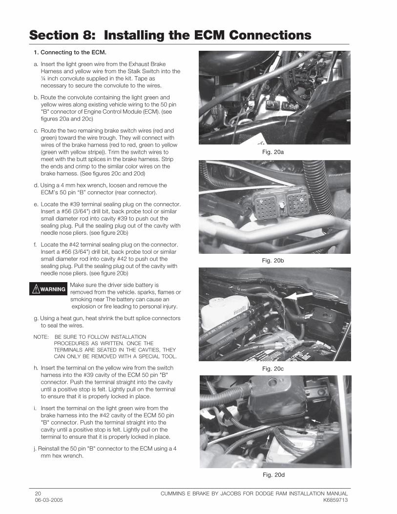
1. Connecting to the ECM.
a. Insert the light green wire from the Exhaust BrakeHarness and yellow wire from the Stalk Switch into the¼ inch convolute supplied in the kit. Tape asnecessary to secure the convolute to the wires.
b. Route the convolute containing the light green andyellow wires along existing vehicle wiring to the 50 pin"B" connector of Engine Control Module (ECM). (seefigures 20a and 20c)
c. Route the two remaining brake switch wires (red andgreen) toward the wire trough. They will connect withwires of the brake harness (red to red, green to yellow(green with yellow stripe)). Trim the switch wires tomeet with the butt splices in the brake harness. Stripthe ends and crimp to the similar color wires on thebrake harness. (See figures 20c and 20d)
d. Using a 4 mm hex wrench, loosen and remove theECM’s 50 pin “B” connector (rear connector).
e. Locate the #39 terminal sealing plug on the connector.Insert a #56 (3/64") drill bit, back probe tool or similarsmall diameter rod into cavity #39 to push out thesealing plug. Pull the sealing plug out of the cavity withneedle nose pliers. (see figure 20b)
f. Locate the #42 terminal sealing plug on the connector.Insert a #56 (3/64") drill bit, back probe tool or similarsmall diameter rod into cavity #42 to push out thesealing plug. Pull the sealing plug out of the cavity withneedle nose pliers. (see figure 20b)
Make sure the driver side battery isremoved from the vehicle. sparks, flames orsmoking near The battery can cause an
explosion or fire leading to personal injury.
g. Using a heat gun, heat shrink the butt splice connectorsto seal the wires.
NOTE: BE SURE TO FOLLOW INSTALLATIONPROCEDURES AS WRITTEN. ONCE THETERMINALS ARE SEATED IN THE CAVTIES, THEYCAN ONLY BE REMOVED WITH A SPECIAL TOOL.
h. Insert the terminal on the yellow wire from the switchharness into the #39 cavity of the ECM 50 pin "B"connector. Push the terminal straight into the cavityuntil a positive stop is felt. Lightly pull on the terminalto ensure that it is properly locked in place.
i. Insert the terminal on the light green wire from thebrake harness into the #42 cavity of the ECM 50 pin"B" connector. Push the terminal straight into thecavity until a positive stop is felt. Lightly pull on theterminal to ensure that it is properly locked in place.
j. Reinstall the 50 pin "B" connector to the ECM using a 4mm hex wrench.

CUMMINS E BRAKE BY JACOBS FOR DODGE RAM INSTALLATION MANUAL 2106-03-2005 K6859713
Section 9: Completing the Installation
Fig. 21a
Fig. 21b
Fig. 21c
Fig. 21d
1. Reinstall the driver side battery
a. Reinstall the driver side battery into the tray and securewith the battery clamp. (see figure 21a)
b. Make sure the negative leads for both batteries are notgrounded and place the positive lead onto the positivebattery post.
c. Remove nut from the clamp and install the fused blackbrake harness wire with eyelet onto the bolt. Replacethe nut and tighten onto the positive battery post. (seefigure 21b)
d. Install the negative battery lead onto the negativebattery post and tighten.
2. Secure the Wiring Harness.
a. Using remaining ¼ inch convolute, tape and securewith tie-wraps to protect the brake wiring harness fromsources of heat and chafing.
b.Tighten the tie wraps holding the wire harness. (seefigure 21c)
3. Reinstall the wheel wells.
Attach the ABS cable to the wheel well. Slide the wheelwell into place. Install Eight (8) cap screws to securethe wheel well to the fender. Repeat for otherside wheelwell. (see figure 21d)
4. Reinstall both front tires.
a. Follow proper procedure from your owners manual toinstall the front tires.
b. Lower vehicle.
5. Reinstall the passenger side battery.
a. Reinstall the passenger side battery into the tray andsecure with the battery clamp. (see figure 21b)
b. Install positive lead onto the positive battery post andtighten.
c. Install negative lead onto the negative battery post andtighten.
6. Reprogram Clock.
Once you have completed the installation, the final stepbefore the test drive is to check the operation of thebrake.

22 CUMMINS E BRAKE BY JACOBS FOR DODGE RAM INSTALLATION MANUAL06-03-2005 K6859713
Section 10: Operational CheckKEEP HANDS, TOOLS ANDELECTRICAL CORDS AWAY FROM THECOOLING FAN AND OTHER MOVINGPARTS. INJURY COULD RESULT.
1. Open the vehicle hood so that you can observe themovement of the vacuum actuator. Make sure thebrake is operating correctly with the enginerunning at idle.
a. Verify that the accessory drive belt is tracking properly.
NOTE: THE BRAKE WILL TURN ITSELF OFF AT IDLECONDITIONS WHENEVER COOLANTTEMPERATURE IS GREATER THAN 170-175DEGREES F.
b. Turn the brake switch to the on position (pull the switchup). The red light on the switch should illuminate and thebrake will activate. You can tell the brake is activated bya change in the engine sound or by observing theactuator arm moving the brake to the closed position.
2. Carefully operate the throttle pedal to bring theengine off idle. The brake should shut off. Watchthe movement of the brake to tell if the brakemoved to the open position.
3. Close the hood and proceed to road test.
If the brake does not operate as described above, turnthe switch to the "OFF" position and check thetroubleshooting section for details on how to proceed.
CUMMINS E BRAKE BY JACOBS FOR DODGE RAM INSTALLATION MANUAL 2306-03-2005 K6859713
Section 11: Exhaust Brake Features
Cruise Control
Your exhaust brake will function during cruise control whenthe cruise is set and the exhaust switch is in the onposition. When coasting and gaining speed, the cruisecontrol will turn the brake on and off to maintain the setspeed.
Warm up device
You can use your exhaust brake to help warm up yourengine. Start your vehicle and turn the stalk switch to theon position. The brake will come on and reduce the time ittakes to get your engine to operating temperature. Whencoolant temperature reaches 170-175 degrees F, thebrake will be automatically turned-off by the Engine ControlModule at idle conditions.
IT IS NOT RECOMMENDED TO IDLEYOUR VEHICLE FOR LONG PERIODSOF TIME.

24 CUMMINS E BRAKE BY JACOBS FOR DODGE RAM INSTALLATION MANUAL06-03-2005 K6859713
Section 12: TroubleshootingBrake will not turn on
NOTE: THE BRAKE WILL TURN ITSELF OFF AT IDLECONDITIONS WHENEVER COOLANT TEMPERATUREIS GREATER THAT 170-175 DEGREES F.
1. With the truck running, check to see if the stalk switch isin the on position and the switch light is illuminated. Ifthe switch is in the on position and the light is notilluminated then go to the electrical troubleshootingsection.
2. Make sure the throttle cable to the TPS is not kinkedor out of position. A kink or out-of-position cable couldgive the TPS an incorrect throttle position reading. TheECM needs to read that the throttle is in the idlepositon for the brake to function.
3. Next step is to go to the Vacuum Troubleshootingsection. If this does not resolve the problem, go to theElectrical Troubleshooting section.
Brake will not shut off1. Hose connections on the solenoid may be reversed.
Hose from vacuum pump should be in solenoidconnection 1. Hose to the brake should be in position2. Numbers will be marked on the solenoid itself.
2. At the solenoid, remove the vacuum hose coming fromthe brake. If the brake does not shut off, the brakemay need to be replaced. Go to BrakeTroubleshooting section.
3. If the brake does shut off in step 2, reconnect thebrake hose and disconnect the solenoid harness. If thebrake shuts off then go to the ElectricalTroubleshooting section. If the brake stays on, replacethe solenoid.
Brake is slow to shut off The filter on solenoid may be clogged. Remove the
filter and clean with solvent and compressed air fromthe back side. If this does not fix the problem, go tothe Brake Troubleshooting section.
Whistling sound from brakeNOTE: SOME SOUND IS NORMAL DURING THE OPERATION
OF THE BRAKE. THE SOUND WILL BE MORE OF AWOOSHING SOUND THEN A WHISTLE.
1. Whistling sound is usually caused by an exhaust leak.Look at and around the brake for carbon tracks.Visible carbon will indicate where the exhaust isleaking.
2. Check the torque of the exhaust brake clamps.
a. Torque the “V” clamp between the turbochargerand exhaust brake. Torque Value: 8.5 N·m [75 in-lb]
b. Torque the “V” clamp between the brake andexhaust pipe. Torque Value: 11.3 N·m [100 in-lb]
3. If the clamps are tight, the gasket might be damaged ormissing. Follow the instructions for installing the brakeand replace the gasket.
Vacuum troubleshooting:
1. Check all vacuum hoses for kinks, leaks or damage.
2. With the engine running, disconnect the vacuum hosefrom both sides of the vacuum solenoid and hold thehoses together. The brake should come on and moveto the closed position. If it does, reconnect the hosesand go to the Electrical Troubleshooting section. Iftesting the vacuum with a vacuum gage, your readingshould be between 15 and 29 inches of mercury.
3. Check to see that the vacuum pump belt is in positionand the vacuum pump pulley and shaft are rotating,spinning with the belt.
4. With the engine shut off, disconnect the vacuum hosefrom the vacuum pump. With the engine running, testfor suction at the vacuum pump with your finger. Ifthere is no suction, replace the vacuum pump.
Electrical troubleshooting:
1. Check 10 amp fuse in wiring harness (driver sidebattery, near positive terminal). If fuse is blown ordamaged, replace the fuse.
2. Disconnect the solenoid connector from the brakeharness. With a Volt/Ohm meter, check the resistancebetween the pins of the solenoid connector. If readingis zero (0) then the solenoid is shorted and should bereplaced. If the reading is over 20 ohms then thesolenoid has an open condition and should bereplaced. The normal resistance reading should bebetween 10 ohms and 20 ohms.
3. With the solenoid connector disconnected and thebrake switch on, turn the key to the on position andcheck the solenoid supply voltage with a Volt/Ohmmeter. 12 Volts should be read between the pins ofthe connector on the brake harness. If there is 12 voltsreplace the solenoid.
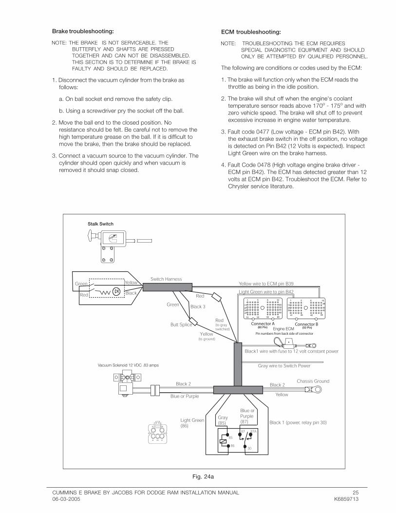
4. Shut the key off and remove the relay base from therelay. Turn the key back on and check the pins in therelay base as follows:
Pin 30 - Battery 12 volts (12 volts)
Pin 85 - Key Switched 12 volts (12 Volts when the key is on)
Pin 86 - To Pin 42 ECM (check continuity between thispin and pin 42 on the ECM connector)
Pin 87 - to Solenoid (check continuity between this pinand solenoid connector)
5. Check wiring against figure 24a.
CUMMINS E BRAKE BY JACOBS FOR DODGE RAM INSTALLATION MANUAL 2506-03-2005 K6859713
Brake troubleshooting:
NOTE: THE BRAKE IS NOT SERVICEABLE. THEBUTTERFLY AND SHAFTS ARE PRESSEDTOGETHER AND CAN NOT BE DISASSEMBLED.THIS SECTION IS TO DETERMINE IF THE BRAKE ISFAULTY AND SHOULD BE REPLACED.
1. Disconnect the vacuum cylinder from the brake asfollows:
a. On ball socket end remove the safety clip.
b. Using a screwdriver pry the socket off the ball.
2. Move the ball end to the closed position. Noresistance should be felt. Be careful not to remove thehigh temperature grease on the ball. If it is difficult tomove the brake, then the brake should be replaced.
3. Connect a vacuum source to the vacuum cylinder. Thecylinder should open quickly and when vacuum isremoved it should snap closed.
ECM troubleshooting:
NOTE: TROUBLESHOOTING THE ECM REQUIRESSPECIAL DIAGNOSTIC EQUIPMENT AND SHOULDONLY BE ATTEMPTED BY QUALIFIED PERSONNEL.
The following are conditions or codes used by the ECM:
1. The brake will function only when the ECM reads thethrottle as being in the idle position.
2. The brake will shut off when the engine's coolanttemperature sensor reads above 170o - 175o and withzero vehicle speed. The brake will shut off to preventexcessive increase in engine water temperature.
3. Fault code 0477 (Low voltage - ECM pin B42). Withthe exhaust brake switch in the off position, no voltageis detected on Pin B42 (12 Volts is expected). InspectLight Green wire on the brake harness.
4. Fault Code 0478 (High voltage engine brake driver -ECM pin B42). The ECM has detected greater than 12volts at ECM pin B42. Troubleshoot the ECM. Refer toChrysler service literature.
Fig. 24a

26 CUMMINS E BRAKE BY JACOBS FOR DODGE RAM INSTALLATION MANUAL06-03-2005 K6859713

CUMMINS E BRAKE BY JACOBS FOR DODGE RAM INSTALLATION MANUAL 2706-03-2005 K6859713

28 CUMMINS E BRAKE BY JACOBS FOR DODGE RAM INSTALLATION MANUAL06-03-2005 K6859713
Cummins Engine Company, Inc.Box 3005Columbus, IN 47202-3005U.S.A.
Bulletin 4081384Printed in U.S.A. 06/05©2005 Cummins Engine Company, Inc. andJacobs Vehicle Systems, Inc. P/N 032414 Rev E