jaguar 3-4 's' and 3·8 's' - holden
TRANSCRIPT

Supplement to "Motor Trader," 4 March 1964
Mo-tor Trader SERVICE DATA NO. 422
JAGUAR 3-4 'S' and 3·8 'S' Manufacturers : Jaguar Cars, Ltd., Coventr:r
❖❖❖❖❖❖❖❖❖❖❖❖❖❖❖❖❖❖❖❖❖❖❖❖❖❖❖❖ ❖ ❖ ❖ All rights res<'rved. 'This Service Data ❖ :S: Sheet is compiled by ·he technical staff of :i: ❖ MOTOR TRADER, f'rom information made ,e.❖ available by the vehicle manufacturers and ❖ t· from ou.r o;vu experience. lt is the copyriglu ::: ❖ oj 1his jottmal, and may not be reproduced. �-❖ in whole or in part, without permi!<sion. •:• i While care is taken w ensure accurac_,, Wf' :::
❖ do not accep1 responsibi!i1y (or error5 or .. :. ❖ omissions. ❖ ❖ � ❖❖❖❖❖❖❖❖❖❖❖❖❖❖❖❖❖❖❖❖❖❖❖❖❖❖❖•:•
LTEST in the range, the "S" -type car
was introduced at the time of the Earls Court Motor Show last year.
This model is an addition to the range, and in size rating comes between the Mk. 2 and the Mk. X. It is conceived as a four-door, four/five seater, and the body is designed on the integral principk. Certain of the mechanical components will be seen to have similarity to those used on other cars in the range, but as might be expected, differ in the specific application to this car.
Motive power is provided by the wellknown six-cylindered overhead camshaft engine. In the case of this car, it is available in either 3.4- or 3.8-litre capacity, and thl=,!e is a choice of compression ratios, with 8:1" quoted as standard for each engine size. In this state, the power output from the 3.4-litre engine is 210 b.h.p. at 5,500 r.p.m., and from the 3.8-litre, 220 b.h.p. at rhe same engine speed. Alternative compression ratios are available for use in countries where fuel requirements make this necessary.
On the transmission side, both manual and fully automatic transmissions are available. When manual transmission is specified, overdrive is optional and when fitted operates on top gear only; synchromesh within the gearbox is fitted to the upper three ratios. The automatic transmission is similar to that which has been described in previous Service Supplement sheets, featuring this Borg-Warner unit. The Supplement numbers are as follows: 260/Cl9, 272/ C25, 344/C59, 352/C63, 354/C63 and 356/ C65 and readers are referred to these publications for full constructional details and repair procedures. The rear axle is the Salisbury 4HU unit and when fitted to the 3.4-litre car may be fitted with the Thornton Powr-Lok differential. This option for the 3.4-litre car is standard on the larger engined (3.8-litre) car.
Suspension is independent front and rear, and drive to the rear road wheels is taken through short universally jointed shafts from either side of the truncated axle shafts to each wheel assembly. Each of these axle output shafts provides the mounting for the discs of inboard rear brakes. The front suspension, of the coil spring and wishbone link pattern, incorporates telescopic hydraulic shock absorbers, as does the rear suspension.
Identification of vehicles varies from previous Jaguar practice. Cars are identified by chassis and engine numbers and the major components have their own numbers. Start-
DISTINGU1SHING FEATURES Frontal styling is somewhat similar to the Mk. 2 cars, but headlamps are recessed and faired into wings. Direction flashers are at lower wing extremities. Wrap around bumpers are fitted front and rear
ing serials are IBlO0l for 3.4-litre cars and IB50001 for the 3.8-litre models, both r.h.d. The chassis number is to be found stamped in the bonnet catch channel forward of the radiator header tank, a suffix "DN" indicated that an overdrive unit is fitted. The engine number is stamped on the right hand side of the cylinder block, above the oil filter and to the front of the cylinder head casting, /7, /8, or /9 following the number denotes the compression ratio. All these numbers, together with other. numerical identification of the car, are to be found stamped on a plate
which is attached to the left-hand front wing valance. On power-assisted steering models,
· this plate is found at the centre of the bulkhead. It is essential that all these numbersand letters are quoted when referring to themanufactur.ers, or when ordering spare parts.
Some special tools are required for servicework, and those considered essential arelisted in the tabular data in this article.
Threads and hexagons are, in the main,of the S.A.E. pattern and form, but certain threaded parts on proprietary componentswill be found to be B.S.F.
INSTRUMENTS, CONTROLS, GEAR POSITIONS AND BONNET LOCK 1. Ammeter 14. Clutch pedal 2. Fuel eauge 15. Headlamp main beam warning 3, Lighhnr; switch light 4. Oil pressure gauge 16. lcnition warning li&ht 5. Water temperature gauce 17. Clock 6. Engine r.p.m. indicator 18. Headlamp dipper switch 7. Speedometer 19. Gearlever (manual trans.l 8. Intermediate rear hold switch (ii 20. Rear outlet control switch
auto. !rans. fitted) 21. Heater control switch 9. Brake fluid level (handbrake 22. R/h control lor lront outlets
warninc licht} 23. Heater temp. control lever 10. Bonnet lock control 24, L/h control for front outlets 11. Handbrake lever 25. Screenwasher switch 12. Accelerator 26. Screenwiper switch 13. Brake pedal 27. Fuel tank chanceover switclt
28. Starter switch 29. Cigar li&hler 30. lcnilion switch 31. Heater fan switch 32. Panel lights switch 33. Interior map light switch 34. R/h flasher warninc licht 35. L/h flasher warninc light 36. Auto. trans. selector, or o'drv.
switch lever 37. Horn 38. Steering wheel adjustment rinr 39. Direction indicator switch/head•
lamps flasher switch
Insets left. from top to bOttom: operative positions of centre mounted manual rearlner control, sitinc of steering column mounted controls. method of releasinc bOnnet salety catch
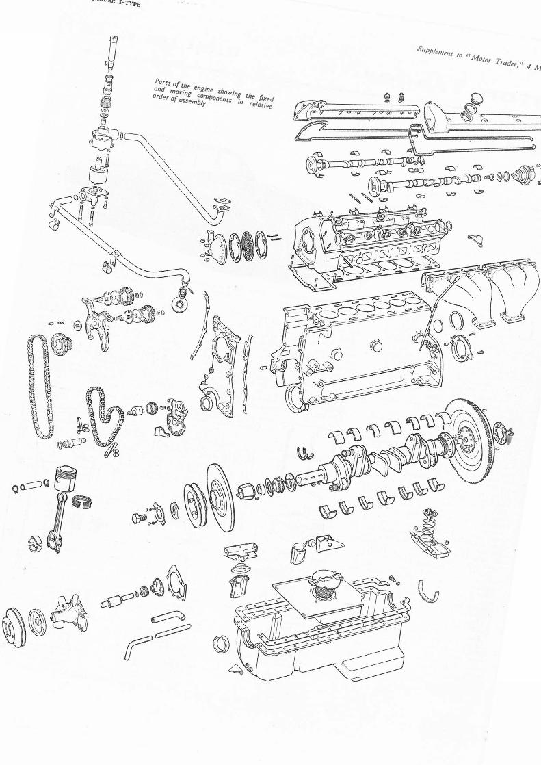
Ports of th and mov· e engine
Order of ing Com
show;n assemb/
Ponent g the fi
y s in ixed
relative
Suppte/J/e,,1 fQ CC Al •�10tor ]j raderJ '' 4 Marcfi 1964

Supplement to "Motor Trader," 4 March 1964
Wheelbase Track: front•
GENERAL DATA
rear Turning circle Ground clearance Tyre size: fronl } rear Overall length Overall width Overall height Weicht (dry)
• 411 4lin, wire wheels
SERVICE TOOLS
ENGINE Upper timinJ chain adjuster Engine liftinc plale Crankshaft rear oil seal sizlnr tool Valve guide bore roamer Valve spring compressor Vain llminr raugo (supplled in 1001 kill Piston ring compressor CLUTCH Universal checklnr; fixture REAR AXLE Pinion bearing cone removal/replacinr;
adaptor Pinion bearing outer bearing cup replac-
ing adaptor Pinion bearinr; inner bearinr; cup replac-
Ing adaptor Differential bearing cone removal adaptor Differential bearing cone replacing adap-
tor Pinion cone setting cauge Hub end-float master spacer Hub-end float dial rauge Hub extractor (disc wheel hubs) Hub extractor (wire wheel hubs) Hub outer bearing cup removal adaptor Hub bearing cup replacing adaptor FRONT SUSPENSION Front coil spring compressor REAR SUSPENSION Rear coil spring compressor Rear wishbone dummy shaft •Use with main tool SL.14-Mulli-purpose
hand press tUse with main tool 550-Mul!i-purpose
handle. t Use with main tool J.20A-Bearinr re-
mover
NUT TIGHTENING TORQUE DATA
ENGINE: Flywheel Connectini Rod Main bearings Cylinder head Camshaft bearinr;s
Bit 11fln 411 7¼1n 411 6¼in 33ft Bin 71n 8.00/6.40 -15 (Road Seeed) 1511 7ft1n 5ft 6¾in 411 6½in 30.7 cwt
Tool No.
J.2 J.8 J.17 J.18 J.6118 C.4015 38.U.3
99
SL.14-1*
SL550-4t
SL.550-St SL14-3•
SL.550-1t SL.3 J.15 J.13 J.1.C J.7 J.16A* J.20A-1t
J.e
J.11A J 14 (2 off)
lb. ft.
67 37 83 54 15
I BALL AND ROLLER BEARING DATA
ENGINE Water Pump
GEARBOX Constanl Mesh
Pinion Malnshaft FRONT AXLE Front hub
(inner) Timken
Outer Timken
Part No. ---
C8167
C1838 C1345
C15351 (LM. 67000/1)
C.15352 (LM. 11900/1)
-1--lnt. Ext. dia.1 dia.,
Width (in or mm) Type ------ ---- - Hollman
No.4083F
40 mm 90 mm B 1jin 3:}in B
- - TR
- - TR
CAMSHAFT
Bearinr Journal: diameler 1.000in ± :::��n
Bearinr clearance .0005-.002in End float .0045-.00Sin Timinr chain: �itch Jin
o. of links (upper) 100 (lower) 82
VALVES
Inlet Exhaust
Head diameter (in) 1¾ ± .002 1i ± .002 Stem diameter (in) .u.:- .0025 fr- .0025 Face .. an:le 45°
Inner Outer
Spring length: :::;d 1.656in 1.935in 1.218in 1.3125in
filled at load 30.33 lb ± J :: 48.375 lb ± �·r�•
ENGINE
Mounting
At front, cylindrical rubber blocks are bonded to studded plates at each end, bolted to brackets on either side of the crankcase and to chassis brackets.
At rear, engine/gearbox unit is supported by spring loaded "T" -piece bolted up to lugs on gearbox extension casing, shank of "T" -piece passes through coil spring and is located and cushioned in rubber bush pressed into channel section support bolted to body floor. Packing blocks fit between flange of channel support and stiffening plates are inserted under heads of mounting bolts.
Removal
Engine should be removed from above, using overhead lifting tackle and trolley jack. If two sets of lifting tackle are available, together with engine lifting plates, trolley jack is not required.
Raise bonnet, mark hinge positions and remove bonnet. Take off air cleaner, disconnect and remove battery, drain sump and remove dip stick. Drain coolant from engine/radiator system, and remove breather pipe (securing clip, flex. pipe/breather housing). Take off screenwasher bottle, disconnect and remove top and bottom water hoses. Disconnect dynamo connections, noting positions for correct replacement of wires; disengage fan belt and remove dynamo unit. Take out radiator matrix, setscrews at sides, and nuts beneath unit. N.B. Unscrew four nuts securing cowl and allow it to rest on water pump housing until matrix is removed.
Disconnect: exhaust system at manifold flanges and heater pipes at rear of engine (clips), remove pipes. Disconnect and/or remove all pipes, wires and controls to and from engine unit and ancillary components.
Remove locknuts and washers from engine stabilisers at front and rear of cylinder head. Take out two setscrews from front mounting rubbers. Detach S.U. carburettors from inlet manifold. Remove gearlever knob, air distribution pipe cover and rubber grommet. Remove cylinder head securing nuts numbers 3, 6, 8 and 9 and fit lifting plate. Support engine/gearbox on lifting tackle and remove eight setscrews from rear mounting member at rear of gearbox or overdrive. Take off propellor shaft. N.B. If vehicle is fitted with auto. transmission observe following: Remove six setscrews securing rear mounting to body floor. Remove two nuts and spring washers securing mounting plate to two rubber mountings attached to rear of transmission. Take off mounting plate, disconnect propellor shaft from gearbox flange, and remove two setscrews securing centre bearing. Disconnect propellor shaft from rear axle flange, and remove propellor shaft. Disconnect control rod from selector lever on nearside of transmission. Remove selector cable clamp from reverse servo cylinder on near front side of transmission, and disconnect governor control rod from governor lever at rear of transmission. Remove leads from " anti-creep " pressure switch and disconnect intermediate speed hold solenoid feed wire at snap connector.
Engine/gearbox unit may now be removed from the car. Refitting is a reversal of above procedure.
Crankshaft
Seven main bearings. Thin wall, steelbacked, white metal-lined shells located by tabs. End float controlled by half thrust washers located in either side of centre bearing cap. No hand fitting permissible. Bearing shells Nos. I, 4 and 7 are interchangeable, as are Nos. 2, 3, 5 and 6. It is possible to change all main bearing shells without removal of crankshaft, but this should be done only in direst emergency. Thrust half-
JAGUAR S•TYPB ·iii
ENGINE DATA
General Type No. of cylinders Bore: mm
in Stroke Capacity: c.c.
CU in
R.A.C. rated h.p.
Max. b.h.p. at r.p.m.
Max. torque lb. ft at r.p.m. Compression ratio
o.h.c. 6
f 83 (3.4 litre) 87 (3.8 litre) 3.2877 (3.4 litre) 3.425 (3.8 litre) 106 mm (4.1732in)
•
i
3,442 (3.4 litre) 3,781 (3.8 litre) 210.6 (3.4 lilreJ 230.6 (3.8 lilre) 25.8 (3.4 litre) 28.15 (3.8 litre) 210
I s,soo (3.4 litre)
220 5,500 (3.8 litre)
I �215 a 3,000 (3.4 lilre) t240 3,000 (3.8 lilre)
7 :1,8 :1 or 9 :1
CRANKSHAFT AND CON. RODS
Main Bearincs Crank pins
Diameter 2.75in 2.086in
--Nos. 2, ,-- -No. 1 3, 5, 6, j No. 4 No. 7
-•:------1 Length (in) ttt 1;, I 1¾ H 1,',
--1------1 Running clearance: main bearinr;s
big ends End float: main bearinrs
big ends Underslzes
Con. rod centres No. of teelh on slarttr rin1 1ear/pinion
PISTONS AND RINGS ----------
.0015-.00lin
.0015-.0033in
.004-.006in
.001-.002sin
:m:.,-030, 7¾in 104/10
Clearance (skirt) .0011-.0017in Oversizes .01 O, .020, .030in
1:1 1 8 :1 I 9 :1
Weicht without rincs ---,.-----i---
or pin 3.4 litre 1 lb 2½ oz 1 lb 3 oz I 1 lb 4 oz 3.8 litre - 1 lb 14 oz. 13 dr.
Gudgeon pin: diameter .8749-.8751in FinJer push flt in
} p11ton @ 68• F Double lhumb push flt in con rod
Compression
No. of rings 2 Gap .015-.020in S"de clearance in
irooves .001-.003in Width of rings .0777-.0787in
Oil Control
1 .015-.033in
Nol applicable Not applicable
washers can be changed by removal of centre-cap.
Flywheel, with integral starter ring gear, spigoted on rear flange of crankshaft, retained by ten setscrews and located by two dowels. Flywheel can be refitted 180 deg. from original setting, but should be fitted with T.D.C. mark set correctly to preserve balanceof assembly. Oil impregnated bronze spigotbearing bush pressed into end of crankshaft.
Oil pump and distributor drive gear (longer boss to rear), timing sprocket (either way), oil thrower, distance-piece and split tapered collet carrying pulley hub are keyed on front end of crankshaft with three Woodruff keys, and retained by setscrew and large washer which bears on pulley hub, to which bonded rubber torsional vibration damper is riveted. Hub is keyed on tapered collet with Woodrufl key. Pulley spigoted and bolted to hub.
Circular oil seal bears on distance-piece behind pulley. Split oil seal housing contains asbestos rope seal and fits round oil return thread on rear end of crankshaft. Lower half, on which cork strip sealing rear of sump fits, bolted to upper half by two Allen head setscrews, with hollow dowels. Upper half dowelled and holted to crankcase.
Connecting Rods
"H "-section stampings, horizontally split big-end bearings, thin-wall steel-backed, lead indium-lined shells located by tabs in caps; no hand fitting permissible.
Small ends bronze bushed for fully floating gudgeon pins.

iy JAGUAR S-TYPB
Pistons
Brico semi-split skirt aluminium alloy. Gudgeon pins located by spring rings. Top compression ring is chromium plated. Pistons should be fitted with cylinder bore number stamped on crown to rear, with split to non-thrust (near) side. Note: that Jaguar practice is to number cylinders from rear to front. Where reference is made in this article to cylinder numbers, our usual practice of numbering from front to rear is maintained.
Maxiflex scraper rings are fitted, and each of these consists of two steel rails with space between. These are held together by special adhesive inserted at initial assembly. When reassembling, ensure that ring ends do not overlap.
Connecting rods will pass through bores, but bolts may have to be extracted. Remove and assemble through top.
Camshafts
· Duplex endless roller chain drive in twostages. First stage drives double idlersprocket and has Renold hydraulic tensioneron offside, rubber rubbing blocks fitted.Second stage passes round idler sprocket,both camshaft sprockets and below smalltensioner sprocket on eccentric hub.
Complete assembly of timing chain sprockets and brackets can be removed after removal of cylinder head, sump and timing cover.
Each camshaft runs in four split steelbacked white metal-lined shells, located by dowels. Oil fed through drillings in head to rear bearings, and through hollow shafts to other bearings. End float of camshaft controlled by shims on front bearing between sprocket and flange on shaft.
When removing head for top overhaul, first slacken chain t.ensioner, then detach each sprocket and slide it inwards along slot.
Before refitting cylinder head, it is important to observe procedure as follows to avoid fouling of inlet and exhaust valves or
valves wi�h pistons, in addition to noting that the engine should not be rotated with camshaft sprockets removed.
Position camshafts, using valve timing gauge provided in tool kit. Key of gauge locates in keyways of camshaft and bottom face of gauge with camshaft cover face on cylinder head. Turn crankshaft to T.D.C. No. 1 firing (mark on crankshaft damper). Check rotor arm position in distributor, refit cylinder head and connect timing chains.
Valves and Tappets
Overhead, set at 70 deg. included angle. Not interchangeable, inlet larger than exhaust. Split cone cotter fixing, double springs with seats between springs and head.
Valve guides plain, no shoulder, noninterchangeable. When renewing, valve guide bores should be reamed to .S0Sin and each guide should be pressed in until outer end projects ftin from spring seat, after total immersion of cylinder head in boiling water for 30 mins.
Valve seat inserts for inlet and exhaust shrunk into light alloy head.
Plain cylindrical tappets fit over valves and slide in guides shrunk into head. Adjust clearance between cam and valve by pad on top of valve stem. Pads are available in thicknesses ranging from 0.85in to .llOin in .001 steps. Pads are identified by etched letters A to Z, A being thinnest. Camshafts must be removed for tappet adjustment.
For removal of valve seat inserts or tappet guides, light alloy head must be heated in oven or muffle for one hour from cold at a temperature of 300 deg. F, when new parts should press in easily.
Lubrication
Hobourn-Eaton eccentric rotor pump fitted, with pressure relief valve situated in filter head. Skew drive gear retained on shaft (Woodruff key) by nut. Shaft runs in
f
0
Supplement to "Motor Trader," 4 March 1964
bronze bush pressed into housing on front of crankcase. Upper end of shaft has offset slot for distributor drive.
When refitting skew gear shaft and bush assembly, turn crankshaft to T.D.C. 1/6, and push in assembly so that, when skew gear meshes with crankshaft gear, slot is parallel to crankshaft centreline, with larger segment towards engine.
Cooling System
Pump and fan. Non-adjustable wax type thermostat in' front end of inlet manifold water jacket.
TRANSMISSION
Clutch
Borg & Beck single dry plate, graphite thrust release bearing, hydraulic actuation through slave cylinder operated by pedal. Only external adjustment is by nut on slave cylinder push rod to give n-in free travel at withdrawal lever.
Access to clutch for service after removal of gearbox and bell-housing.
Gearbox
Four speed, synchromesh on 2nd, 3rd and top gears. Single helical gear forms.
To Remove Gearbox
Gearbox should be removed with engine unit as detailed in engine section. It is not possible to remove gearbox as a separate unit.
To dismantle gearbox, remove top cover with remote control assembly, selector rods and forks. Engage top and 1st gears to lock box, and undo driving flange nut. Draw off flange, extract speedo drive pinion and detach rear cover with lipped oil seal complete with layshaft and reverse spindles.
0 (Q) G..,,_a ""-[{ ---�(o)
�---=====:=z;:;- -=:::::7
OOCC: □�-: �� 0
Parts of the gearbox, showing the gear trains and selector mechanism, together with the gearcasing
Supplement to "Motor Trader," 4 March 1964
Draw off speedo drive gear and thick washer. Using suitable extractor withdraw rear
ball bearing from mainshaft. Remove bellhousing and front bearing cover with lipped oil seal (note copper washers under setscrew heads). Turn primary shaft so that cut-away on top gear dogs clears layshaft constant mesh gear. Tap mainshaft forward to drive out primary shaft and ball bearing with caged roller spigot bearing. Mainshaft assembly can then be lifted out through top. Lift out layshaft cluster with needle roller bearings and thrust washers, and bushed reverse idler.
Primary shaft ball bearing retained on shaft with chip shield by nut and locknut.
To dismantle mainshaft assembly slide off top/3rd synchro assembly, noting interlocking plunger and ball in drilling through synchro hub. Press down plunger in shaft, locking 3rd gear splined thrust washer, releasing washer. Slide off 3rd gear with 41 needle rollers. Remove 1st gear and synchro assembly (same as top/3rd gear, with interlocking plunger and ball). Remove 2nd gear (same as 3rd gear). When reassembling note that interlocking plunger and ball in top/3rd and 2nd synchro hubs must be opposite cutaway splines on mainshaft and in synchro sleeves.
Reverse idler spindle should not be separated from rear extension housing as rubber sealing ring recessed in spindle cannot be replaced without special thimble.
When reassembling box insert small retaining rings in layshaft needle roller recesses, and insert 29 needle rollers in each end, sticking them in with thick grease. Insert outer retaining ring in front end of shaft with large bronze thrust washer. Stick on steel thrust washer (pegged to box). Insert stepped steel washer at rear (pegged to shaft) and small bronze thrust washer. Insert reverse gear into casing. Lower cluster into box and insert thin rod to support it.
Move reverse gear and lever forward in casing. Feed in mainshaft and primary shaft assemblies, and drive in ball bearing. Lift layshaft cluster with rod and insert dummy spindle .980in in diameter, with generous chamfer on end, into layshaft so as not to disturb needle rollers. Assemble distancepiece and speedo gear on mainshaft, and offer up rear extension housing with Jayshaft spindle, and reverse spindle. Insert laysihaft spindle, pushing out dummy spindle to front, picking up reverse gear on spindle as rear extension is pushed home. Complete assembly of box.
Rear Axle
Salisbury 4HU, mounted independently from hubs and road wheels, Thornton PowrLok differential unit as standard on 3.8-litre models and is optional on 3.4-litre cars. Short drive shafts, with universal joints at each end are coupled to axle output shafts and each shaft provides mounting location for discs of inboard rear brakes. Axle ratio is stamped on tag attached to assembly by one of detachable rear cover securing screws.
Rear Suspension
Independent coil springs and telescopic dampers. Universally jointed half-shafts form top "links,'' and lower links are pivoted at wheel carrier and axle cross-member ends respectively.
Suspension medium provided by four coil springs, each containing telescopic dampers, and mounted in pairs each side of the differential casing. Complete assembly is carried in steel cross-beam mounted to the body on four "V "-rubber blocks, located by radius arms, pivots of which are rubber bushed and mounted either side of car, between lower link and body structure.
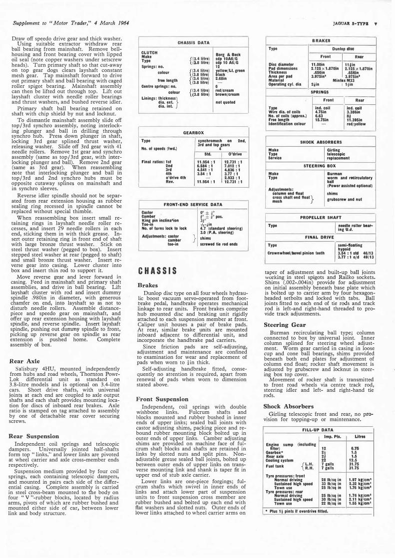
CHASSIS DATA
CLUTCH Bore & Beck Make Type {l3-4 lilrej sdp 10A8/G
3.8 litre sdp 10 A6/G Springs: no. 12
colour
F.4 litre) ,,now/Lt. creen
3.8 litre) lack free lencth (3.4 lilre) 2.68in
(3.8 litre) Centre sprlnc•: no. 6
colour f3.4 lilre) red/cream (3.8 litre) brown/cream
Linincs: thickness} dia. ext. not quoted
dia. lnt.
GEARBOX
Type synchromesh on 2nd,
No. ol speeds (fwd.) 3rd and top gears
4 Sid. O'drive
Final ratios: 111 11.954 : 1 12.731 : 1 2nd 6.584 : 1 7.012 : 1 3rd 4.541 : 1 4.836 : 1 4th 3.54 : 1 3.77 : 1 o'drlve 4th - 2.933 : 1
I Rev. 11.954 : 1 12.731 : 1
FRONT-END SERVICE DATA
Castor Camber Kine pin incllna•ion Toe-in No. of turns lock to lock
Adjustments: cutor cam,er toe-in
CHASSIS
Brakes
'
}
o• ± t• ¾0 ± ¼0 pos. 3¾°
,'r•iln 4.7 (standard steering) 3.0 (P.A. steerinf) shims screwed lie rod ends
Dunlop disc type on all four wheels hydraulic boost vacuum servo-operated from footbrake pedal, handbrake operates mechanical linkage to rear units. Front brakes comprise hub mounted disc and braking unit rigidly attached to each suspension member at front. Caliper unit houses a pair of brake pads. At rear, similar brake units are mounted inboard adjacent to differential unit, and incorporate the handbrake pad carriers.
Since friction pads are self-adjusting, adjustment and maintenance are confined to examination for wear and replacement of pads when worn to ¼in thick.
Self-adjusting handbrake fitted, consequently no attention is required, apart from renewal of pads when worn to dimension stated above.
Front Suspension
Independent, roil springs with double wishbone links. Fulcrum shafts and blocks mounted and rubber bushed in inner ends of upper links; sealed ball joints with castor adjusting shims, packing piece and rebound rubber mounting block bolted up in outer ends of upper links. Camber adjusting shims are provided on machine face of fulcrum shaft blocks and shafts are retained in links by slotted nuts and split pins. Nonadjustable grease sealed ball joints, bolted up between outer ends of upper links on transverse mounting link and shank is taper fit in upper end of stub axle carrier.
Lower links are one-piece forgings; fulcrum shafts which swivel in inner ends of links and attach lower part of suspension units to front suspension cross member are rubber bushed and bolted up each end with flat washers and slotted nuts. Outer ends of lower links attached to wheel carrier arms on
JAOUAlt S•TYPI Y
B RAKES
Type Dunlop 'lsc
Front RNr
Disc diameter 11.00in 11jln Pad dimensions 2.125 X 1.8701n 2.125 X 1.8701n Thickness .656in .658ln Area fer pad 3.9751n' 3.9751n' Mater al Mintex M33 Operatinc cyl. dia 2iln I 1½in
SPRINGS
Front I Rear
�fr: dia. ol coils ind. coil Ind. coll 4.75in 3.3861n
No. ol coils (approx.) 6.63 8¼ Free lencth 15.751n 11.3951n Identification colour - red/yellow
SHOCK ABSORBERS
Make Type Service
telescopic replacement
Make Type
I Girlinc
STEERING BOX
IBurman worm and rtclrculalory ball (Power 111isttd optional)
AdJu1tm1nt1: column end float shims cross shaft end float} mesh crub1crew and nut
PROPELLER SHAFT
Type I needle roller bear-inc U.J.
FINAL DRIVE
Type
CrownwflHl/lltnl pinion teeth hypoid I seml-floalinc
3.54 : 1 ltd 46/13 3.77: 1 o/d 49/13
taper of adjustment and built-up ball joints working in steel spigots and Railko sockets. Shims (.002-.004in) provide for adjustment on initial assembly beneath base plate which is bolted up to carrier arm by four hexagonheaded setbolts and locked with tabs. Ball joints fitted to each end of tie rods and track rod is left-and right-hand threaded to provide track adjustments.
Steering Gear
Burman recirculating ball type; column connected to box by universal joint. Inner column splined for steering wheel adjustment. Worm gear carried in casing in loose cup and cone ball bearings, shims provided beneath both end plates for adjustment of column end float; rocker shaft movement is adjusted by grubscrew and locknut in steering box top cover.
Movement of rocker shaft is transmitted to front road wheels via centre track rod, steering idler and left- and right-hand tie rods.
Shock Absorbers
Girling telescopic front and rear, no provision for topping-up or maintenance.
FILL-UP DATA Imp. Pls. Ulm
EnGiine sump (includlnc ,.111 Iler) 12
Gearbox• 2½ 1.5 Rear ule 2f 1.5 Coolinc system 22 12.5 Fuel tank {L.H. 7 galls 31.75
R.H. 7 galls 31.75
Tyre pressures: front 28 lb/sq in 1.97 k1/cm• Normal driving
Sustained hich speed 33 lb/sq in 2.32 kf/cm• Town use 25 lb/sq in 1.76 kf/cm•
Tyre pressures: rear 25 lb/sq in 1.76 kg;/cm• Normal driving
Sustained hi&h speed 30 lb/sq In 2.11 kflcm• Town use 22 lb/sq in 1.55 kf/Cm'
• Plus 1 l pints II overdrln fitted.

vi JAGUAR S-TYPE
Parts of the front suspension, rear a,de and the_ steeri�g assemblies. Note that the Thornton Powr-Lock d1 fferent10I shown in lower portion of drawing is standard fitmel)t tp 3,8./itre cars, and option,.al 0/1 other ll)Odtl
� 0.) 0
'
a @)
�
" C
Supplement to "Motor Trader," 4 March 1964
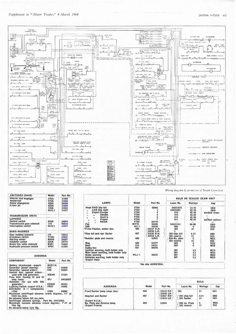
LUCAS EQUIPMENT
•BATTERY Model BV11A •GENERATOR Model C42
I PartNo. 22902
•CONTROL BOX Model RB340 Part No. 37331 STARTING MOTOR Model M45G Part No. 26140
Drive pre-engaged •DISTRIBUTOR Model 22D6 I Part No. 40885
(
Max. centrilupl advance (crank degrees) 19 at 3400 rov./min.
No advance below 200 r.p.m. 7 : 1 and 8 : 1 Centrilural advance springs. Compression Ratio Part No. 54415559
Max. vacuum advance (crank degrees) 6°-8° at 25 in. Hg.
No advance below Sin Hg. IGNITION COIL Model HA12 I Part No. 45104
Primary rasistance 3.0-3.5 ohms Running current at 1,000 r.p.m.
WINDSCREEN WIPER
HORN(S)
FLASHER UNIT •FUSE UNIT
1.0 amp.
Model DR3. Part No. 75361 RHD 75374 LHD
Model 9H Part No(s) 54068078 low note
54068079 high note Typo: Windtone Current consumption 3,0•3½ amp.
(per horn) Model FL5 Part No. 35020 Model 4FJ Part No. 54038032 Fuse ratings 35 amp.
35 amp.
• Seo also ADDENDA.
SWITCHES Model Part No. -----Ignition 545 31962 Starter S55 34263 Starter solenoid 2ST 76464
•Lighting PRS7 34382 Direction indicator and H/lamp
flash 85SA 34803 Dip 103SA 34536 Stop light HLZ 31802 Wiper 79SA 31966 Steering column control ccz 33585 Cubby boxlight 54SA 34379
•see also ADDENDA. --,---1
Supplement to "Motor Trader," 4 March 1964
r-ir - •
•lt-1-c::,-..-Jo.- •-·-c:>-;.:o!�ICN •� I ,'.,-7'..._..J..:.: °:ll!�I'. -.MW� LIG�' 1.;!t�) i f ·•1-...C)-...J.o... __ -�-----t,
�AIN IEAM W"RNll'IIG Ll(;Hl �-
SWITCHES (Contd) 1�, Part No. Interior and mapli1ht
m! 31960
Heater/Ian 31960 Petrol changeover 458A 34425 Soreen Jet 65SA 31984
128A 31504 SS10/1 310TT
TRANSMISSION UNITS ---
LAYCOCK ---
Control switch 9DSA 34804 Transmission cear solenoid 11S 76515 Interruption switch SS10/1 31077
BORG-WARNER Gear holdinc solenoid 118 76533 Kickdown switch T10SI 31931 Starling motor M45G 26097 Inhibitor switch 55SA 34774 Brake line valve solenoid BVS1 76502 Hydraulic pressure switch HPS1 31393
ADDENDA
COMPONENT Model Part No.
Battery (drycharged-export) BVZ11A Generator (power steering) C42 22906 Generator (special orders) C48 22804 Control Box (special order$--
used with C48 generator) RB340 37354 Fuse Unit (havinc 35 and 50
amp. fuses) 4FJ 54038007 Ammeter (for use with C48
ceneralor) CZU60 36293 Lighting Switch (export u.s.A.) PRS7 34382 Distributor (9 : 1 compression
ratio) 22D6 40886 Maximum centrifugal advance (crank degrees), 13° al
2000 rev./min. No advance below 225 rev./mln. Centrifugal advance springs. Part No. 54415560. Maximum vacuum advance (crank decrees). 7"-9° at
15in He, No advance below 2lin H&.
S.OIL"""" -...II.NIH(; L•G,.T Q?M,- ...OOU.$ ONLY)
LAMPS
Head RHO Dip leil LHD 01 right "
" Export urope " " Sweden " " Austria " " France
Foi ·• NADA
Side •Front Flasher, amber lens
•stop tail and rear flasher
•Number plate and reverse
Map Boot Cubb1 box lgnihon warning1 bulb holder only Main beam warninc, bulb holder only Brake warning Sidelamp warninc, bulb holder only (Export Italy) ---
ADDENDA
Front flasher lamp (clear lens)
Slop/tail and flasher
(Export U.S.A.) No. Plate and Reverse lamp (Export France)
I Model Part No.
F700 58962 F700 3 F700 4 F700 5 F700 6 F700 7 F700 59175
WFT6 55285 461/1 52636
690 l
52637 R.H.
� 52638 LH.
687 53935 R.H. 53934 L.H.
689 53943
689 524TT 519 54121 681 56078
WL3/1 38220
r I I
JAGUAR S-TYPE yjj
IGNIT� COi\ lll�tfl:1Uo,t
., �QUt,.�o �l(&oii-'-' --{�=!------Ill .,,.,.0 I._A�t: w.t.P.N,,K,. LH;lf1
' OvtRMfYt: c111.,:un I
I cONrlOOL SWJfCN FUSC GUii\ 10( �lfll'Ct-1 j
)--o/o--c-()>cO-c-'-c �-..... =-..:-7-0-J t !.Ol.tN010 I
� :��S� =G: 5��� .. �� - � r - -ii•
---;,<=>c:L_,--.:
-�- l'.;N (,N ·-
r" �"I (!,l.t.NCUII.O .,.0t)lL1" I .i..L__jR£Y'!:RS,{ LU;;MT ONLv) N
I ;1
·· ,. i'" ., """' '""' . i 1,,---� i i i
L--·-·-·-·- I
�I•
l!IOAG • wlJ:tf<ll llt"'-$1,'iSSIOf,I £0U1J>...,,if
u.11., .. MOOD.!.°"'-' "'"01 YU• CAILI
0,
---ii• "'"' ,,u,.,;; ,._.,.,.,
Wiring diagram by permiss1011 of 1oseph Lucas Ltd.
I
I BULB OR SEALED BEAM UNIT
I Lucas No. '
Wattage I Cap
54521872 b0/45 SBU 54520481 60/45 SBU
410 45/40 Unified (clear) 410 45/40 ,. 410 45/40 ,, 411 45/40 Unified (yellO\Y) - -
54522163 60/45 SBU 989 6 MCC 382 21 sec 3
380 stop tail 6/21 SBC 382 reverse 21 sec
{ 989 No. pla(e 6 MCC 382 reverse 21 sec
989 6 MCC 989 6 MCC
987 2.2 MES 987 2.2 MES 987 2.2 MES 987 2.2 MES
.See also ADDENDA . _I
BULB
Model Part No. Lucas No. Wattage Cap
690 r
2639 RH}
382 21 sec 52640 LH
687 53937 RH { 380 stop/tail 6/21 SBC 53934 LH 382 flasher 21 sec
689 53944 { 989 no. Plate 6 MCC 382 reverse 21 sec
I

viii JAGUAR S-TYPE
24 33
16 8 5 3 25
28 1 26 30 9 27 21 25 6 36
KEY TO MAINTENANCE DIAGRAM
DAI LY l. Radiator } check and top up 2. Engine sump
WEEKLY 3. Tyre pressures-check
MONTHLY 4. Battery-check and top up
EVERY 3,0 0 0 MILES 5. Tyre pressures check
8. Auto, trans. (if fitted) 9. Power assisted steering (if fitted) check and
�: ·::!i::;r }
10. Clutch and brake master cyls. top up 11. Gearbox 12. Rear axle 13. Carburettor piston dampers 14. Engine sump-drain and refill 15. Engine oil filter element-clean 16. Distributor-oil shaft bearing, auto. advance
mechanism, and contact breaker pivot, smear cam with grease
E Y E R Y 6 , 0 0 0 M I L E S (as for 3,000 Miles plus followinE)
17. Steering unit (std. type)-check and top up 18. Engine oil filter element-renew
*19. Fuel feed lines and carburettor filters-clean
21. Steering tie rod ends , grease gun 20. Wheel swivels
} 22. Wishbone pivots (rear) mner
ends
RECOMMENDED LUBRICANTS
MOBIL
Above 90° F Mobiloil AF
Engine 32° to 90° F Mobiloil A
Below 32° F Mobiloil Arctic
Encin� oils •Multigrade
Mobiloil Special
Gearbox, Distributor, Oil can Mobiloil A
Rear axle Mobilube GX 90
stiering box (sld. steering) Mobilube GX 140
Wheel hubs and distributor cam, steerinc Mobllgroase idler, tie rods, wheel swivels and door MP hinges
Aulomatic transmission Mobilftuid 200 Power st11rin1 system
Upper cylinder lubricant Upperlube
23. Wishbone pivots (rear) outer} ends 24. Brake set'VO air cleaner-clean and lubricate
with brake fluid 25. Brake friction pads-examine for wear 26. Top timing chain-adjust for wear
�
if necessary
�i: i�:n
�e1':�::�1:!ignment check *29. Seat runners, door catches, locks,
hinges, etc. oil can 30. Generator end bush
E Y E R Y 1 2 , 0 0 0 M I L E S (as lor 6,000 Miles plus following)
31. Gearbox (and o'drive, if fitted) }drain and 32. Rear axle fill 33. Auto. transmission (if fitted) re
34. Overdrive oil pump filter (if o'drive fitted)-clean
35. Engine air cleaner element-renew 36. Power steering oil reservoir filter-renew 37. Front and rear wheel hubs-grease, check end
float of bearings *Not shown on diagram.
DRAINING POINTS Radiator matrix drain tap control is adjacent to nearside top of radiator, visible and accessible from beneath bonnet. Cylinder block drain tap is on block casting, adjacent to and above dip stick, on nearside of engine unit
CASTROL SHELL ESSO
XXL X-100 40 Extra Motor Oil 40
XL X-100 30 Extra Motor Oil
Castrolile X-100 20W 20W/30
Caslrolite or XL X-100 Multigrade 10W/30 or 20W/40 Extra l'tlotor Oil
XL X-100 30 10W/30
Hypoy Spirax 90 EP Gear Oil GP 90
Hi-Press Spirax 140 EP Gear Oil ST 140
Castro lease Retinax A Multi purpose LM Grease H
T.Q. Donax T.6 Automatic Transmission Fluid
Castrollo Donax U or UCL UCL
Supplement to "Motor Trader," 4 March 1964
5 3
See ,ol. 3 p. v for FILL-UP DATA
TUNE-UP DATA
Firing order Tappet clearance (cold):
inlet exhaust
Valve timing: inlet opens inlet closes exhaust opens exhaust closes
Standard ignition timing
Location of timing mark
Plugs: make type size gap
Carburettor: make type
Settings: choke main jet needle fuel level
Air cleaner:
Fuel pump:
make type make type
1, 5, 3, 6, 2, 4
.004in
.006in
15° BTDC 57° ABDC 57° BBDC 15° ATDC
{7 to 1 comp. ratio-TDC 8 to 1 comp. ratio-7° BTOC 9 to 1 comp. ratio-5° BTDC
Timing marks on engine damper. Pointer on sump. Champion UN12Y 14mm .025in s.u. H.D.6 (twin)
.100in T.L. ftin
AC paper element s.u. AUF300 series
B.P. DUCK HAM'S REGENT
·Energol SAE 40 NOL 40 Advanced Havoline 40
EnerEol SAE 30 NOL 30 Advanced Havoline 30
Energol SAE 20 NOL 20 Advanced Havoline 20/20W
Energol Q20-50 or Advanced Visco-static Q5500 Havoline Special
20W/40 or10W/30
Energol SAE 30 NOL 30 Advanced Havoline 30
Energol SAE 90 Hypoid 90 un;versal EP Thuban 90
Energol NOL EP 140 Universal SAE 140 EP 140 Thuban
Energnase L2 LB 10 Marlak Mullipurpose 2
Energol ATF Nolmatic Teumatic Type A Fluid
Energol U.C.L. Adcoid Liquid U.C.L.
Brake and clutch ftuid reservoirs Dunlop Disc Brake Fluid (S.A.E. 70 R.3) or other brands al S.A.E. Spee. 70 R.3
•These oils should NOT be used in worn engines, whose general condition indicates that overhaul is required.
Printed 1n England by Cornwall Press Ltd., Paris Garden, London, S.E.J.