james fenwick - engineering design 4 ieee paper (rmit)
TRANSCRIPT

Abstract — The primary objective of a conventional
lightning protection system is to maximize the electric field
above the structure on which it is installed when it is subject to
the electrostatic meteorological environment of a
thunderstorm. This results in the promotion of successful
streamer to leader propagation which ultimately improves the
likelihood of the controlled earth termination of a cloud to
ground (CG) lightning strike. A conventional lightning
protection system is designed to prevent damage to a building
by providing a number of preferential strike receptors (air
terminals) with low impedance paths to conduct the lightning
discharge safely to ground. In this study, via the utilization of
Finite Element Analysis (FEA) software and solid modelling
Computer Aided Design software, several air terminal
topologies comprising conventional and non-conventional
geometrical surface characteristics were modelled in detail and
then subject to an electrostatic simulation environment
(thunderstorm replica) for analysis of their respective electric
field distributions. Results indicate discrepancies of up to
100KV in electric field distribution between that of the
conventional and non-conventional air terminal topologies.
This suggests that significant research opportunities lie within
optimizing the geometrical design of a conventional air
terminal with respect to its corona emission capabilities and
could ultimately lead to a review of LPS protocols embodied in
many national and international Lightning Protection
Standards.
Keywords – Lightning, Lightning Protection System, LPS, Air
Terminal Design, Surface Characteristics, Electric Field
Distribution, finite element modelling.
I. INTRODUCTION
HAT happens on the earth’s surface during a
thunderstorm is extremely relative to what is
happening in the clouds above. The negative charge in a
thundercloud induces a positive charge on the earth’s surface
beneath it. The natural space charge produced by pointed
corona emitting objects such as trees, power lines, antennas
buildings and the like, limits the electric field at ground level
to typically around 10kV/m [3]. In the presence of a
thunderstorm, and on closer approach of the negatively
charged descending stepped leader, the fields at the sharp
conducting points of exposed objects are intensified to such
Manuscript received October 14, 2015; Revised October 14, 2015. Paper
no. RMIT-3332395-2015. James T. Fenwick is an undergraduate student with the school of
Electrical and Computer Engineering, Royal Melbourne Institute of
Technology, Melbourne, Victoria, Australia; (e-mail: [email protected])
an extent that they can reach the voltage breakdown level of
air. [3][6][7][8] When this happens, the pointed object emit
corona current which induces a positive spacial charge
above it that is strong enough to produce a positive electrical
discharge (streamer) that propagates towards the descending
leader. If the leader is close enough to ground such that the
electric field between them is strong enough to sustain a
positive streamer, successful streamer to leader propagation
occurs and the provision of a successful lightning discharge
path is established. [2]
The purpose in which a conventional lightning protection
system is intended to operate, is via the meticulous
positioning of lightning strike receptors (air terminals) with
low impedance paths (down conductors) to conduct the
lightning discharge safely to ground (earth termination
network). Preliminary insight into the relation of lightning to
grounded objects was first explored by Benjamin Franklin in
the 18th
century. Franklin later went on to conceptualize the
architecture of what is now considered to be a conventional
lightning protection system by identifying three key
elements; metallic rods (Air Terminals), horizontal roof
conductor networks, and vertical down conductors
connected to earth termination networks. The first ever air
terminals used by Franklin were thin, sharp tipped needles
mounted on to the top of iron rods, since then various
geometrical topologies have been investigated in an effort to
improve their lightning interception capabilities.[11]
Generally speaking, air terminals are considered to offer a
zone of protection to a structure relative to their electric field
distribution capabilities and other risk factors according to
many national and international lightning protection
standards. The basic principles of LPS design have been
embodied in such standards as the Australian and New
Zealand Lightning Protection Standard. This standard, like
many others, does not endorse or imply the endorsement of
non-conventional LPSs that claim enhanced performance. [1]
Irrespective of limitations imposed by such standards, a vast
array of literature exists investigating the claimed enhanced
performance of non-conventional LPSs but on a consistent
basis there is an absence of relevant conclusive results and
this suggests that they do not function as they claim.[2][3][4][5]
In this study, several air terminals comprising
conventional and non-conventional surface characteristics
are modelled in detail using Solid Works Computer Aided
Optimization of Conventional Air Terminal Design for Lightning
Protection Systems with Respect to Geometrical Surface
Characteristics
James T. Fenwick, Student, RMIT
W

Design (CAD) software. To allow for electrostatic analysis
of these designs, a 3-dimensional electrostatic simulation
model, replicating the meteorological conditions of a
thunderstorm, was built using ANSYS Maxwell Finite
Element Analysis (FEA) software. Each air terminal
topology was subject to the same simulation conditions for
comparative analysis of their respective electric field
distribution. Results outline the impact that geometry has on
an air terminal’s electrostatic performance capabilities and
provides preliminary insight into the optimization of
conventional air terminal design.
II. ELECTROSTATIC ENVIRONMENTAL PROPERTIES OF A
THUNDERSTORM
The cloud most commonly associated with a thunderstorm
is called the cumulonimbus cloud. This cloud structure is
typically characterized by a towering and dense, vertical
cloud in which strong rising air currents called updrafts are
present. The presence of these updrafts are believed to
instigate charge distribution within the cloud, smaller
particles rise to the top of the cloud via the updrafts and
acquire a positive charge whereas the larger particles
accumulate at the bottom of the cloud acquiring a negative
charge. The concentration of positive charges in the top of
the cloud and that of the negative charges in the bottom of
the cloud creates a significantly large potential difference
not only between different regions of the cloud, but also
between the bottom of the cloud and the earth. When this
potential difference becomes significant enough, the
phenomenon more formally known as lightning takes place
and bridges the two regions of charge via an ionized channel
that works to neutralize the intervening field.
A common method used to model the charge distribution
of a cumulonimbus cloud is the Simpson Cumulonimbus
Model. [10] In this model cumulonimbus cloud is broken into
three spheres of uniform distributing charges. The cloud
model below consists of three point charges suspended in air
at different heights from the ground. In the simulation, the
ground has been modelled with a boundary condition of odd
symmetry (Flux Normal) where E is normal to the boundary;
its normal components are 0. The surrounding walls of the
simulation region have been assigned a balloon boundary
condition, where the charge at the"infinity" balances the
charge in the drawing region. The net charge is 0. The three
charges of 3C, -40C and +40C are placed at heights of 2, 7
and 12km from ground level respectively. The charges are
modelled as spheres of radii 900m for the positive and
negative 40C charges, and radii 150m for the 3C charge. The
size of the spheres is picked in such a way that when the
meshing process takes place, the electric fields in the area of
interest within the model are accurate. The initial mesh
settings for this simulation are 1 meter. [9] On closer
inspection of the electrostatic simulation depicted in Fig. 1
we can see that the ground electric field rapidly runs to 0 as
the radius increases laterally from the vertical centreline. [10]
Fig. 1. Electrostatic simulation of Simpson Cumulonimbus Model [10]
III. LPS AIR TERMINAL MODELLING
Three air terminals were modelled in Solid Works CAD.
Each air terminal was designed at a height of 1 meter, a
radius of 9.5mm and assigned aluminum (Grade 1050)
material properties (as specified by [1]) with a bulk
conductivity of 38 Mega Siemens/m and a relative
permittivity of 1. One conventional air terminal was
modelled as the reference air terminal and is depicted in the
far left of Fig 2. This model featured conventional smooth
surface characteristics and ultimately generated the reference
data used to analyze its non-conventional counterparts. Two
non-conventional air terminals were modelled, both
comprising surface characteristic alterations. The air
terminal comprising surface characteristic #1 depicted in the
middle of Fig. 2 demonstrated a “knurled” rough surface in
which diamond like cut-outs and extrusions texturized the
terminal from top to bottom. The air terminal comprising
surface characteristic #2 depicted at the far right of Fig. 2
demonstrated a “pyramid swept” surface in which pyramid
like cut-outs and extrusions texturized the terminal from top
to bottom with a “zig-zag” like shape.
Fig. 2. Air Terminal Solid Works Models, (LEFT) Conventional
Reference Air Terminal, (MIDDLE) Non-Conventional Air Terminal
Surface Characteristic #1, (RIGHT) Non-Conventional Air Terminal
Surface Characteristic #2
IV. 3 DIMENSIONAL AIR TERMINAL ELECTROSTATIC
SIMULATION MODEL
The 3 dimensional electrostatic simulation model used for
the analysis of each air terminal topology consisted of a
2000mm x 2000mm x 200mm rectangular prism suspended
directly above the air terminal at a height of 2000mm,
therefore allowing a gap of 1000mm between the tip of the
air terminal and the under croft of the rectangular prism.
In order to mimic the excitation values of a thunderstorm
and its associated charge distribution, the rectangular prism
was assigned an excitation value of -10MV to emulate the
potential difference associated with the tip of the negative
downward leader and ground as stated in [10]. The air
terminals were then assigned an excitation value of +10KV
which is believed to be the electric field potential at ground
level under the presence of a thundercloud. Once all
excitations had successfully been assigned, a virtual force
was assigned to the rectangular prism and a region was
created in which the simulations would populate with
results. The floor of the region was assigned a boundary
condition of odd symmetry (normal flux). Finally a polyline
was drawn on the simulation as a non-model object. The
poly line was drawn horizontally 500mm directly above the
tip of the air terminal spanning 1.5 meters each way, this line
was ultimately used as a reference for the rectangular plots
that were utilized in the analysis of each air terminal’s
electric field distribution. Initial mesh settings for each
simulation were set at 0.001mm so to allow for recognition
of surface characteristic alterations.
V. PRELIMINARY INDIVIDUAL SIMULATION RESULTS
The following simulations depicted in Figures 3, 4, and 5
embody the preliminary stages of the electrostatic analysis
performed on each respective air terminal topology.
Fig. 3. 3 Dimensional Conventional Air Terminal Electrostatic Simulation
Figure 3 depicts the electric field distribution of a
conventional air terminal when a field overlay displaying
electric field magnitude is applied. From these results, a
rectangular plot was generated based on the values generated
at each point along the polyline, and the data was exported
and tabulated in excel.
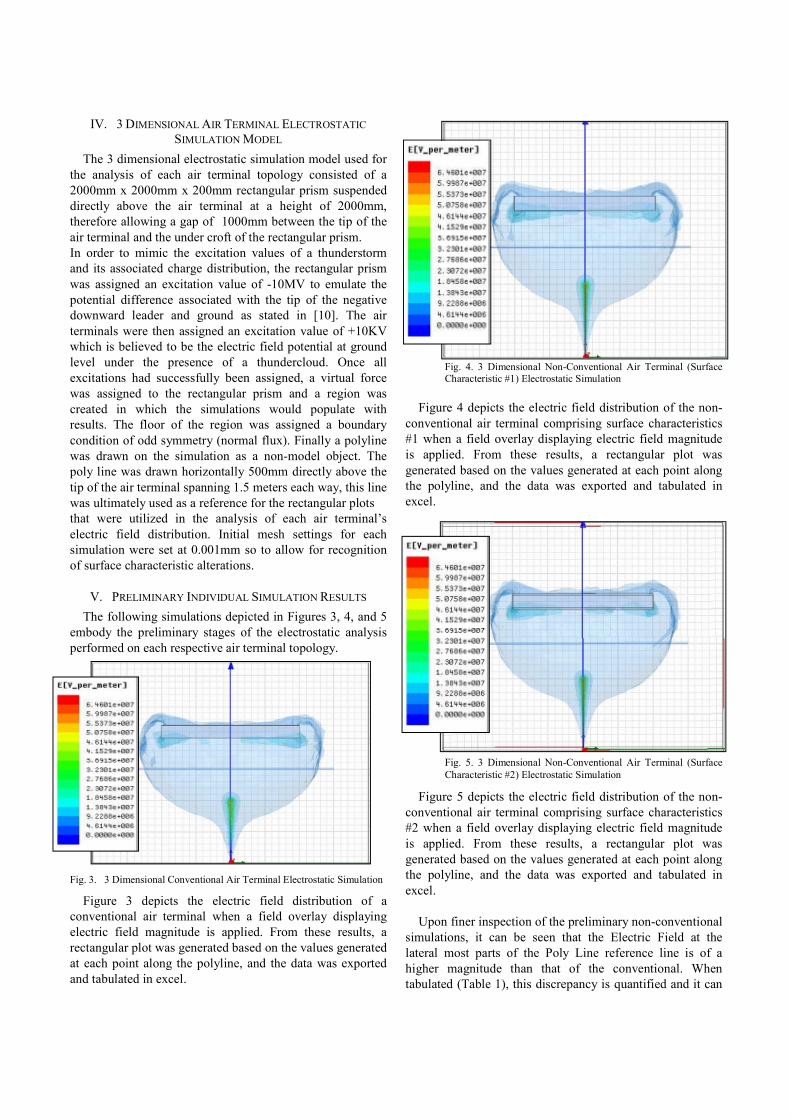
Fig. 4. 3 Dimensional Non-Conventional Air Terminal (Surface Characteristic #1) Electrostatic Simulation
Figure 4 depicts the electric field distribution of the non-
conventional air terminal comprising surface characteristics
#1 when a field overlay displaying electric field magnitude
is applied. From these results, a rectangular plot was
generated based on the values generated at each point along
the polyline, and the data was exported and tabulated in
excel.
Fig. 5. 3 Dimensional Non-Conventional Air Terminal (Surface
Characteristic #2) Electrostatic Simulation
Figure 5 depicts the electric field distribution of the non-
conventional air terminal comprising surface characteristics
#2 when a field overlay displaying electric field magnitude
is applied. From these results, a rectangular plot was
generated based on the values generated at each point along
the polyline, and the data was exported and tabulated in
excel.
Upon finer inspection of the preliminary non-conventional
simulations, it can be seen that the Electric Field at the
lateral most parts of the Poly Line reference line is of a
higher magnitude than that of the conventional. When
tabulated (Table 1), this discrepancy is quantified and it can

be seen that although electric fields are of a higher
magnitudes at the most lateral parts of the distribution,
magnitudes are significantly smaller directly above the non-
conventional air terminals when compared with that of the
conventional.
Table 1. Poly Line Electric Field Data Extracted From Preliminary
Electrostatic Simulations
VI. SECONDARY SIMULATION RESULTS
To further explore the preliminary electrostatic simulation
results of Part V., a secondary set of simulations were run to
analyze whether or not the conventional and non-
conventional air terminals would complement each other if
laid out in an array like manor. For this simulation, each air
terminal topology was laid out in the same configuration and
put under the same analysis for electric field distribution
capabilities. A simulation was also run utilizing both air
terminal topologies and results were analyzed.
The layout of air terminals for this configuration consisted
of a star like formation utilizing a total of five air terminals.
The electrostatic simulation environment they were subject
to was equivalent to that of Part V. Air terminals were offset
600mm in +x, -x, +z, and –z directions from the reference
air terminal located at 0,0,0,0 (+x, -x, +z, -z) at ground level.
Each air terminal was assigned a positive voltage of 10KV
similar to that of the preliminary simulation environment
and all results were exported to a single rectangular plot
which is analyzed in Part VII. of this report. For these
simulations the non-conventional air terminal model
comprising surface characteristics #1 was omitted from
simulations due to meshing problems.
Fig. 6. 3 Dimensional Conventional Air Terminal Electrostatic
Simulation (Secondary Array)
Figure 6 depicts the electric field distribution of the
conventional air terminal laid out in an array like manor
when a field overlay displaying electric field magnitude is
applied. From these results, a rectangular plot was generated
based on the values generated at each point along the
polyline, the data was exported and tabulated in excel.
Fig. 7. 3 Dimensional Non-Conventional (Surface Characteristics #2)
Air Terminal Electrostatic Simulation (Secondary Array)
Figure 7 depicts the electric field distribution of the
conventional air terminal laid out in an array like manor
when a field overlay displaying electric field magnitude is
applied. From these results, a rectangular plot was generated
based on the values generated at each point along the
polyline, the data was exported and tabulated in excel.
In addition to the simulations conducted in Figures 6 and
7, a third simulation was run that utilized both conventional
and non-conventional (Surface Characteristic #2) air
terminal topologies. To achieve the best possible layout for
this simulation, the conventional air terminal was used as the
reference air terminal located at 0,0,0,0 (+x, -x, +z, -z), the
non-conventional air terminals were offset in the same
fashion as the previous simulations and the results were also
included in the rectangular field plot in Part VII. for
analysis.
0.00 0.50 1.00 1.50 2.00 2.50 3.00Distance [meter]
4.00E+006
4.50E+006
5.00E+006
5.50E+006
6.00E+006
6.50E+006
7.00E+006
Y1
[V
_p
er_
me
ter]
Maxwell3DDesign1Electric Field Distribution Plot ANSOFT
Curve Info
MixedImported
ConventionalSetup1 : LastAdaptive
Non-Conventional SC2Imported
Fig. 8. 3 Dimensional Non-Conventional & Conventional(Surface
Characteristics #2) Air Terminal Electrostatic Simulation (Secondary
Array)
Figure 8 depicts the electric field distribution of the mixed
conventional/non-conventional air terminal layout when a
field overlay displaying electric field magnitude is applied.
From these results, a rectangular plot was generated based
on the values generated at each point along the polyline, the
data was exported and tabulated in excel.
VII. ANALYSIS OF RESULTS
Upon the successful completion of all secondary
simulations the electric field distribution data for each layout
was plotted on one rectangular plot and is depicted below in
Graph. 1.
Graph 1. Electric Field Distribution Rectangular Plot
When analyzing discrepancies between electric field
distributions it is evident when looking at the plot that the
conventional system is still the most effective system for
overhead electric field maximization. The air terminals
comprising surface characteristic alterations have little
beneficial effect on electric field distribution other than
producing higher electric field magnitude at the most lateral
parts of the field distribution, this includes when they are
laid in conjunction with conventional air terminals. These
results have remained consistent throughout both
preliminary and secondary simulations. For a more
quantifiable analysis of the secondary simulations, data was
exported from the distribution plot and tabulated in excel
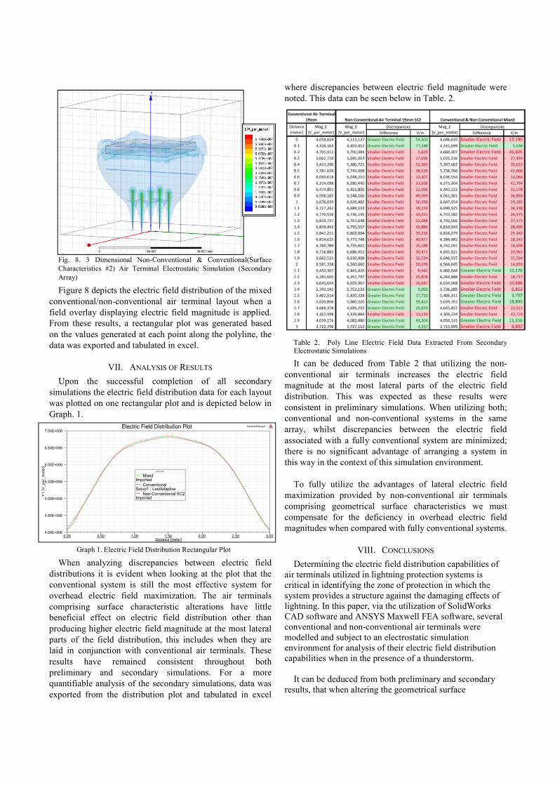
where discrepancies between electric field magnitude were
noted. This data can be seen below in Table. 2.
Table 2. Poly Line Electric Field Data Extracted From Secondary Electrostatic Simulations
It can be deduced from Table 2 that utilizing the non-
conventional air terminals increases the electric field
magnitude at the most lateral parts of the electric field
distribution. This was expected as these results were
consistent in preliminary simulations. When utilizing both;
conventional and non-conventional systems in the same
array, whilst discrepancies between the electric field
associated with a fully conventional system are minimized;
there is no significant advantage of arranging a system in
this way in the context of this simulation environment.
To fully utilize the advantages of lateral electric field
maximization provided by non-conventional air terminals
comprising geometrical surface characteristics we must
compensate for the deficiency in overhead electric field
magnitudes when compared with fully conventional systems.
VIII. CONCLUSIONS
Determining the electric field distribution capabilities of
air terminals utilized in lightning protection systems is
critical in identifying the zone of protection in which the
system provides a structure against the damaging effects of
lightning. In this paper, via the utilization of SolidWorks
CAD software and ANSYS Maxwell FEA software, several
conventional and non-conventional air terminals were
modelled and subject to an electrostatic simulation
environment for analysis of their electric field distribution
capabilities when in the presence of a thunderstorm.
It can be deduced from both preliminary and secondary
results, that when altering the geometrical surface

characteristics of grounded structures in a thunderstorm
environment, their electric field distribution capabilities
change considerably. In the context of this analysis, although
electric field magnitudes were maximized at the most lateral
parts of electric field distribution for air terminals
comprising geometrical surface characteristic alterations,
this comes at a somewhat proportional depreciation in
overhead electric field intensity. Ultimately, to gain full
advantage of lateral electric field maximization provided by
such non-conventional air terminals we must compensate for
the co-ordinate reduction in overhead electric field intensity.
This paper has analyzed the affects that minor alterations
made to a conventional air terminal’s geometry can have on
its respective electric field distribution capabilities. Both
industry standard conventional, and non-conventional air
terminals have been analyzed, and the effects of air terminal
surface geometry have been identified as worthy of
consideration when designing a lightning protection system.
REFERENCES
[1] EL-024 Technical Committee, Protection Against Lightning, Council of Standards Australia, Council of Standards New Zealand.
“Australian/New Zealand Standard, Lighting Protection”, AS/NZS
1768:2007, pp. 11 - 133 (2007) [2] Van Brunt, R.J.; Nelson, T.L.; Stricklett, K.L. “Early streamer
emission lightning protection systems: An overview”, Electrical Insulation Magazine, IEEE, Volume:16, Issue: 1, pp. 5-24 (2000)
[3] Rison, W. “Experimental validation of conventional and
nonconventional lightning protection systems”, Power Engineering
Society General Meeting, IEEE, Volume: 4. (2003) [4] Tobias, J.M., “The Basis of Conventional Lightning Protection
Systems”, IEEE Transactions on Industry Applications, Volume: 40,
No. 4, July/August (2004) [5] Zipse, D.W., “Lightning Protection Systems: Advantages and
Disadvantages”, in Proceedings of the IEEE Petroleum and Chemical
Industry Technical Conference (St Louis, MO USA), p. 343, IEEE, (1993)
[6] Alconchel, O. and Thirion, B., “Study of a type of early streamer
emission lightning conductor”, in Workshop on Physics of Lightning (Chamonix, France), (1993)
[7] Lee, J.B., Myung, S.H., Cho, Y.G., Chang, S.H., Kim, J.S., and Kil,
G.S., “Experimental Study on Lightning Protection Performance of Air Terminals”, International Conference on Power System
Technology, 2002. Proceedings. PowerCon 2002, Volume: 4, (2002)
[8] Becerra, M., Cooray, V., and Roman, F., “Lightning Striking Distance of Complex Structures”, Generation, Transmission & Distribution,
IET, Volume: 2, Issue: 1, (2008)
[9] Peesapati, V. ; Cotton, I., “Lightning protection of wind turbines — A comparison of real lightning strike data and finite element lightning attachment analysis”, International Conference on Sustainable Power
Generation and Supply, 2009. SUPERGEN '09., (2009) [10] Xiangyu Liu ; Jiaqing Chen ; Yingqiang Wang ; Jun Liu ; Zaihui
Wang, “Finite-difference analysis of the atmosphere electric field
distribution around a thunderstorm monomer”, 2012 6th Asia-Pacific Conference on Environmental Electromagnetics (CEEM), (2012)
[11] Cooray, Vernon, “Lightning Protection”, Power and Energy Series 58,
IET, (2009)