january 2012 - ddot 2012. dc streetcar design criteria january 2012 terry bellamy | ddot director...
TRANSCRIPT
DC StreetcarDesign Criteria
January 2012
DC STREETCAR DESIGN CRITERIA
January 2012
Terry Bellamy | DDOT Director
Ronaldo Nicholson, PE | Chief Engineer
Angel A. Pena Project Manager | Civil Engineer
Progressive Transportation Services Administration 55 M Street SE, Suite 500
Washington DC 20003
www.ddot.dc.gov
MESSAGE FROM DDOT DIRECTOR AND CHIEF ENGINEER
We are very pleased to announce the completion of the DC Streetcar Design Criteria. This manual marks a significant milestone for the District Department of Transportation as we prepare to restore streetcar service to the District. The DC Streetcar Design Criteria will provide both general guidelines and specific criteria for the planning, design and construction of the proposed streetcar system. We are confident that the use of this manual will enable DDOT, agencies, consultants, planners, engineers and other professionals to more efficiently translate DC requirements into acceptable design solutions. Implementing a successful streetcar system that will serve the District of Columbia is our key goal. With the development of this Design Criteria and Standard Drawings we have taken a very important step towards this direction.
Terry Bellamy Ronaldo Nicholson, PE
DDOT Director Chief Engineer

FOREWORD
The DC Streetcar Design Criteria is the first comprehensive document that provides a general framework and the basis for a uniform design for the proposed DC streetcar system. These criteria will allow the city’s project team and partners to develop preliminary and final designs for any streetcar project that might be undertaken by the District Department of Transportation.
These guidelines are not intended to replace the level of initiative and competence expected from DDOT, agencies, consultants, and professionals in the performance of their duties. It is not a substitute for engineering judgment and sound engineering practice. Professionals involved in the DC streetcar program are encouraged to carefully consider the principles of the Design Criteria in the context of the needs of individual projects. Exceptions may apply in special cases. If a guideline is not appropriate and that a more appropriate solution is available, suggestions to this effect should be raised for consideration by DDOT. The DC Streetcar Design Criteria should be viewed as a ”living document,” which is subject to change or revisions as we continue to work towards our goal to implement a successful extensive streetcar system in the city. A strong foundation is needed that provides guidance to achieving this goal. The completion of this Design Criteria is one the steps towards achieving this foundation.
Angel A. Pena Project Manager | Civil Engineer
Progressive Transportation Services Administration
ACKNOWLEDGEMENTS
The Design Criteria for DC Streetcar was prepared under the guidance of the District Department of Transportation Technical Working Group with the assistance of HDR Engineering Inc. in association with ZGF Architects LLP, LTK Engineering Services, and Legion Design. Many Thanks to the people who helped make this document possible:
DDOT Technical Working Group:
Office of the Director: Terry Bellamy/ Director
• Sandy Castor • Monica Hernandez
Infrastructure Project Management Administration (IPMA): Ronaldo Nicholson, PE/ Chief Engineer
• Muhammed.Khalid • Ali Shakeri • Ronald Garraffa
Progressive Transportation Services Administration (PTSA): Aaron Overman, PE/ Acting Associate Director
• Angel A. Pena • Eric Madison
• Marti Reinfeld • Ralph Burns
Traffic Operation Services Administration (TOA): Dr. Gloria Jeff/ Associate Director
• James Cheeks • Lamont Hinton
• Wasim Raja • Levon Petrosian • William Handsfield
Policy, Planning and Sustainability Administration (PPSA): Sam Zimbabwe/ Associate Director
• Maurice Keys • Reginald Bazile • Jim Sebastian
• Gabe Onyeador • Alice Kelly • David Krulewitch
Urban Forestry Administration (UFA): John P. Thomas/ Associate Director
• Earl Eutsler • Sharon Dendy
Public Space Operations Project (PSOP): Jeff Powell/ Acting Associate Director
• Juan Amaya • Matthew Marco
HDR Engineering Inc:
• Kevin LaGreca
ZGF Architects LLP:
• Otto Condon
LTK Engineering Services:
• Mike Collins
Legion Design:
• Jason Casey
The District Department of Transportation wishes to acknowledge the following government agencies and private sector companies from the interested parties group for their input and feedback in the content of this document:
Interested Parties Group:
• District Department of the Environment (DDOE)
• Arlington County, Virginia
• PEPCO
• VERIZON
• SPRINT/NEXTEL
DC Streetcar Design Criteria Manual | Table of Contents vi
Table of Contents
1.0 General 1.1. Purpose and Scope 1.2. Climate/Environmental Conditions 1.3. System Technology Description 1.4. Application 1.5. Codes and Standards 1.6. Project Goals
2.0 Operations 2.1 General 2.2 Operations 2.3 Equipment and Facilities 2.4 Fare Collection and Enforcement 2.5 Supervisory Control 2.6 Safety and Security
3.0 Track Alignment and Vehicle Clearance 3.1 Track Alignment 3.2 Clearance Requirements
4.0 Urban Design - Streetcar Stops 4.1 Preferred Siting Criteria 4.2 Streetcar Platforms 4.3 Streetcar Platform Design Parameters 4.4 Streetcar Platform Amenities 4.5 Integration of Public Art
5.0 Civil Work 5.1 Survey Control System 5.2 Drainage 5.3 Right-of-Way 5.4 Roadways 5.5 Grading
DC Streetcar Design Criteria Manual | Table of Contents vii
6.0 Urban Design - Potential R.O.W. and Alignment Improvements
6.1 Goals and Criteria for Integrating Related Improvements 6.2 Streetscape and Low Impact Development Strategies 6.3 Trackway Design Goals 6.4 Infrastructure
7.0 Utilities 7.1 Preconstruction 7.2 Gas Lines 7.3 Sanitary, Storm and Water 7.4 Electrical Power Facilities 7.5 Telephone, Fiber Optic, Long Distance and Cable TV Facilities 7.6 Street Lights and Traffic Signals 7.7 Parking Meters and Pay & Display Kiosks 7.8 Vaults and Basement Encroachments 7.9 Overhead Utility Lines 7.10 Utility Design Drawings 7.11 Temporary Support of Track Slab for Utility Maintenance and Replacement
8.0 Traffic 8.1 Applicable Codes 8.2 General Design Criteria 8.3 Control of Streetcar Interface with Traffic 8.4 Sign Design 8.5 Pavement Marking Design 8.6 General Operations 8.7 Traffic Control through Work Zones
9.0 Trackwork 9.1 Trackway 9.2 Trackwork 9.3 Electrical Insulation 9.4 Special Trackwork
10.0 Structural 10.1 General 10.2 Applicable Codes and Standards 10.3 Loads and Forces
DC Streetcar Design Criteria Manual | Table of Contents viii
10.4 Soils 10.5 Reinforced and Prestressed Concrete 10.6 Structural Steel 10.7 Foundations 10.8 Support of Excavation Structures 10.9 Streetcar Tracks on Bridges
11.0 Vehicles 11.1 Vehicle Type 11.2 Handicapped Accessibility 11.3 Operating Environment 11.4 Traction Power Supply Voltages 11.5 Vehicle Weight and Passenger Loadings 11.6 Vehicle Dimensions 11.7 Vehicle Performance 11.8 Vehicle Noise 11.9 Vehicle Vibration 11.10 Electromagnetic Interference & Compatibility
12.0 Maintenance and Storage Facility 12.1 General 12.2 Applicable Codes and Standards 12.3 Materials of Construction 12.4 Structural 12.5 Facility Vehicle Interface 12.6 Corrosion Control and Safety Grounding 12.7 Acoustics 12.8 Maintenance 12.9 Mechanical Systems 12.10 Access for the Mobility Impaired 12.11 Functional Requirements 12.12 Site Selection 12.13 Storage Yard 12.14 Interior Cleaning Area 12.15 Automobile Parking and On-site Roads 12.16 Outside Storage Areas 12.17 Fire Protection System 12.18 Yard Lighting 12.19 Security 12.20 Refuse/Recycling Collection 12.21 Landscaping
DC Streetcar Design Criteria Manual | Table of Contents ix
12.22 Streetcar Shop Layout 12.23 Shop Functional Areas 12.24 Support Areas for Shops 12.25 Central Maintenance, Operations and Administrative Areas 12.26 Exterior Streetcar Wash Facility 12.27 Electrical Services
13.0 Traction Power Supply & Distribution 13.1 General 13.2 Requirements 13.3 Traction Power Substations 13.4 DC Feeder System 13.5 Overhead Contact System 13.6 Negative Return Path and Stray Current Control
14.0 Stray Current and Corrosion Control 14.1 Purpose 14.2 Scope 14.3 Interfaces 14.4 Applicability of Criteria 14.5 Expansion Capability 14.6 Standards and Codes 14.7 Special Design Provisions 14.8 Stray Current Corrosion Prevention 14.9 Stray Current Corrosion Prevention Systems 14.10 Soil Corrosion Control (Buried Structures) 14.11 Soil Corrosion Prevention Systems 14.12 Atmospheric Corrosion Prevention 14.13 Atmospheric Corrosion Prevention Systems 14.14 Grounding 14.15 Design and Coordination of Grounding Systems
15.0 Signal and Route Control 15.1 General 15.2 Applicable Codes and Standards 15.3 Functional Design Requirements 15.4 Operational Design Requirements 15.5 Electromagnetic Interference 15.6 Growth and Expansion 15.7 Switch Machines 15.8 Traffic Signal Interface and Streetcar Signals
DC Streetcar Design Criteria Manual | Table of Contents x
16.0 Communications 16.1 General 16.2 Supervisory Control and Data Acquisition 16.3 Station Platforms 16.4 Vehicles 16.5 Traction Power Substations
17.0 Fare Collection 17.1 Fare Collection Equipment 17.2 Fare Structure 17.3 Fare Enforcement
Chapter 1General
Content
1.1. Purpose and Scope 1.2. Climate/Environmental Conditions 1.3. System Technology Description 1.4. Application 1.5. Codes and Standards 1.6. Project Goals
DC Streetcar Design Criteria Manual | General 1-1
1.0 General
1.1. Purpose and Scope
The purpose of the design criteria is to establish the standards and design policies for the preliminary engineering and final design phases for the DC Streetcar Program. The material contained herein is intended to provide a uniform basis for the design of any streetcar project that might be undertaken by the District Department of Transportation. Its purpose is to provide sufficient information to allow the development of preliminary and final designs including estimates of capital, operating and maintenance costs, and determination of the potential impacts of operations and construction on the communities.
The following design criteria provides the basis for uniform design and is not a substitute for engineering judgment and sound engineering practices that will be required during project development. It is the responsibility of the designer to expand upon the general framework of the design criteria to a level of detail consistent with the level of design. The designers are encouraged to analyze alternative approaches to solving design problems to determine the most cost-effective and environmentally sound solution.
These design criteria are to be used by designers to develop designs that meet the intent stated. In situations where deviations to the criteria are encountered, the designer is to submit a written waiver request to the District Department of Transportation (DDOT) for approval of such deviations. Upon final submission of the Plans, Specifications, and Estimates, all deviations shall be approved by DDOT and filed for review by the Quality Auditor.
1.2. Climate/Environmental Conditions
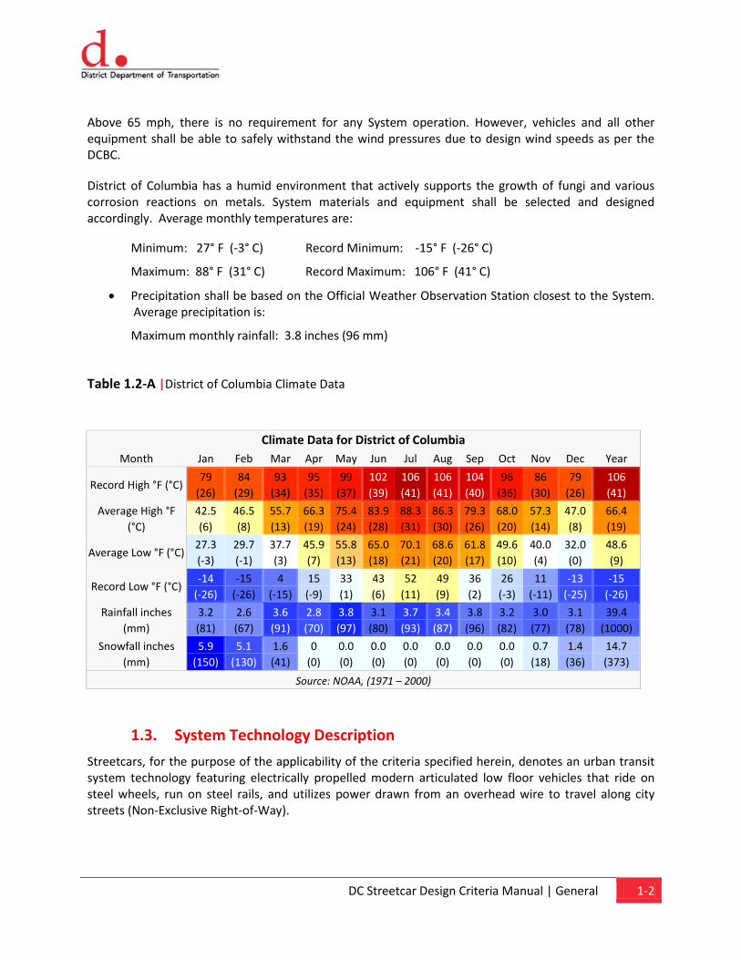
The Project will be located in a region that has a humid subtropical climate. Summers are hot, humid and wet. July is the warmest month, with an average high of 88°F (31°C) and an average low of 70°F (21°C). Winters are generally cool to cold, with occasional snowfall. January is the coldest month, with an average high of 42°F (6°C) and an average low of 27°F (-3°C). Precipitation is fairly evenly distributed each month, averaging 40 inches of rainfall and 15 inches of snowfall annually. Table 1.2-A shows the average, maximum and minimum temperatures in the DC area.
The Systems structural integrity, with trains stopped on any guideway section, shall withstand wind pressures determined in accordance with the District of Columbia Building Code (DCBC), as adopted by the District of Columbia, with no damage to the train or appurtenant equipment. Wind velocity for computing the previous when the train is not in sheltered storage shall be 65 mph. When the train is in sheltered storage, the wind velocity shall comply with the requirements of the DCBC. The minimum safety factors against failure shall be per the DCBC.
The System shall be capable of operating under varying wind conditions. In sustained winds up to and including 45 mph, the System shall be capable of normal operations, meeting all requirements of the contract. In sustained wind conditions above 45 mph and below 65 mph, the System shall operate safely, but allowing up to 25 percent degradation in overall performance (e.g., train velocity, acceleration, and deceleration).
DC Streetcar Design Criteria Manual | General 1-2
Above 65 mph, there is no requirement for any System operation. However, vehicles and all other equipment shall be able to safely withstand the wind pressures due to design wind speeds as per the DCBC.
District of Columbia has a humid environment that actively supports the growth of fungi and various corrosion reactions on metals. System materials and equipment shall be selected and designed accordingly. Average monthly temperatures are:
Minimum: 27° F (-3° C) Record Minimum: -15° F (-26° C)
Maximum: 88° F (31° C) Record Maximum: 106° F (41° C)
• Precipitation shall be based on the Official Weather Observation Station closest to the System. Average precipitation is:
Maximum monthly rainfall: 3.8 inches (96 mm)
Table 1.2-A |District of Columbia Climate Data
1.3. System Technology Description
Streetcars, for the purpose of the applicability of the criteria specified herein, denotes an urban transit system technology featuring electrically propelled modern articulated low floor vehicles that ride on steel wheels, run on steel rails, and utilizes power drawn from an overhead wire to travel along city streets (Non-Exclusive Right-of-Way).
Climate Data for District of Columbia Month Jan Feb Mar Apr May Jun Jul Aug Sep Oct Nov Dec Year
Record High °F (°C) 79
(26) 84
(29) 93
(34) 95
(35) 99
(37) 102 (39)
106 (41)
106 (41)
104 (40)
96 (36)
86 (30)
79 (26)
106 (41)
Average High °F (°C)
42.5 (6)
46.5 (8)
55.7 (13)
66.3 (19)
75.4 (24)
83.9 (28)
88.3 (31)
86.3 (30)
79.3 (26)
68.0 (20)
57.3 (14)
47.0 (8)
66.4 (19)
Average Low °F (°C) 27.3 (-3)
29.7 (-1)
37.7 (3)
45.9 (7)
55.8 (13)
65.0 (18)
70.1 (21)
68.6 (20)
61.8 (17)
49.6 (10)
40.0 (4)
32.0 (0)
48.6 (9)
Record Low °F (°C) -14
(-26) -15
(-26) 4
(-15) 15 (-9)
33 (1)
43 (6)
52 (11)
49 (9)
36 (2)
26 (-3)
11 (-11)
-13 (-25)
-15 (-26)
Rainfall inches (mm)
3.2 (81)
2.6 (67)
3.6 (91)
2.8 (70)
3.8 (97)
3.1 (80)
3.7 (93)
3.4 (87)
3.8 (96)
3.2 (82)
3.0 (77)
3.1 (78)
39.4 (1000)
Snowfall inches (mm)
5.9 (150)
5.1 (130)
1.6 (41)
0 (0)
0.0 (0)
0.0 (0)
0.0 (0)
0.0 (0)
0.0 (0)
0.0 (0)
0.7 (18)
1.4 (36)
14.7 (373)
Source: NOAA, (1971 – 2000)
DC Streetcar Design Criteria Manual | General 1-3
1.4. Application
The material contained in the following chapters provides a uniform basis for design and is expected to be refined and expanded during engineering design.
This design criteria manual represents a recommended set of uniform and minimum guidelines for use in the development, design, engineering, and implementation of the DC Streetcar Program. It is not a specification and therefore, the following criteria are intended to set minimum guidelines to assure design uniformity and consistency of systems, components, and facilities of streetcar infrastructure.
These criteria serve as guidelines and do not substitute for engineering judgment and sound engineering practice. Specific exceptions may apply in special cases. The designers are responsible for identifying any necessary departure from the criteria contained in this document, and then notifying the District Department of Transportation Project Manager. Any exceptions from or changes to the criteria must be reviewed and approved by the District Department of Transportation prior to use in the design. Applications for change in criteria, additions to the criteria, and other questions shall be submitted in writing.
This criteria manual may periodically require revisions to reflect changes in environment, industry, engineering, operation, and maintenance, or to reflect policy changes.
1.5. Codes and Standards
The designer is fully and solely responsible for determining all applicable codes and standards for the proposed work. The Designer, at a minimum, shall comply with the requirements of the following codes. Additional codes and standards, laws and ordinances and requirements shall be determined by the Designer. In case of conflicts between the criteria, standards, codes, regulations, ordinances, etc. the more stringent requirement shall govern unless otherwise directed, in writing, by the District Department of Transportation.
The Streetcar alignment will interface with different entities and Authorities Having Jurisdiction (AHJ). Entities and AHJ include but are not limited to the following:
• AASHTO, A Current Policy on Geometric Design of Highways and Streets (2004)
• AASHTO, Guide for Design of Pavement Structures, 4th Edition (with 1998 supplement)
• AASHTO, Roadside Design Guide, 3rd Edition
• AASHTO, Guidelines for Skid Resistant Pavement Design
• AASHTO, Information Guide for Roadway Lighting
• AASHTO, Guide for Development of Bicycle Facilities
• American Society for Testing of Materials (ASTM)
• Bicycle Interactions and Streetcars, Lessons Learned and Recommendations, Prepared for the Lloyd District Transportation Management Association (LDTMA), Prepared by Alta Planning + Design

DC Streetcar Design Criteria Manual | General 1-4
• Manual of Uniform Traffic Control Devices (MUTCD-2009)
• Code of Federal Regulations (CFR)
• ADA Accessibility Guidelines for Buildings and Facilities (ADAAG)
• Uniform Federal Accessibility Standards (UFAS)
• DDOT Design and Engineering Manual (2009)
• DDOT Standard Specifications for Highways and Structures (2009)
• DDOT Standard Drawings (2009)
• DDOT Design Guidelines for Traffic Calming Measures for Residential Streets in the District of Columbia, 2005
• DDOT Public Realm Design Handbook
• DDOT Right of Way Policies and Procedures Manual
• DDOT Temporary Traffic Control Manual Guidelines and Standards, 2006
• DDOT Work Zone Safety and Mobility Policy, 2007.
• DDOT, Pedestrian Master Plan (Draft, 2008 May)
• DDOT, Bicycle Facility Design Guide
• DDOT, Policies and Procedures Manual for School Area Pedestrian Safety DDOT, Anacostia Waterfront Transportation Architecture Design Standards
• DDOT, Policy and Process for Access to the District of Columbia Interstate and Freeway System
• District of Columbia Traffic Calming Policies and Guidelines, 2002
• WMATA, Tram-LRT Guidelines
• WMATA Adjacent Construction Project Manual
• DC Water, Standard Details and Guidelines (2008)
• DC Water, Specifications
• DDOE, Stormwater Guidebook (2008)
• DDOE, Standards and Specifications for Erosion and Sediment Control (2003)
• Catalog of Recommended Pavement Rehabilitation Design Feature for the District of Columbia
• Catalog of Recommended Pavement Reconstruction Design Feature for the District of Columbia
• Life-Cycle Cost Analysis and Load Carrying Capacity for the District of Columbia
The Designer shall be responsible for determining all entities and the AHJ that may be impacted by the Designer’s work and/or may have jurisdiction over the Designer’s work. The Designer’s work shall conform to all the requirements and minimum standards/guidelines adopted by the AHJ. In cases of conflict, the more stringent requirements shall govern.
DC Streetcar Design Criteria Manual | General 1-5
Where no provision is made in the codes for particular features of the design, the best current industry practice shall be followed. The list below is a preliminary guide of applicable codes/standards and requirements that must be complied with. The Designer shall evaluate and include all other applicable codes and standards in the design. The latest edition of the applicable codes and/or standards shall be followed.
• DC Building Code as applicable and all references and standards cited therein
• DC Accessibility Code (and the Americans with Disabilities Act)
• AASHTO: American Association of State Highway and Transportation Officials
• District Department of Transportation (DDOT) requirements
• Relevant ASHRAE, ASPE, ANSI, NFPA, and ASTM Standards
• National Electric Code (NEC)
• District of Columbia Ordinances
Agencies or entities who publish/author codes, standards and other requirements that may be applicable to the project are listed below. The following is a partial list and it is the Designer’s legal, contractual and professional duty to design in accordance with all the applicable requirements, whether or not referenced herein.
• American Association of State Highway and Transportation Officials (AASHTO)
• Americans With Disabilities Act (ADA)
• American Concrete Institute (ACI)
• American Society for Testing Materials (ASTM)
• American Institute of Steel Construction (AISC)
• American National Standards Institute (ANSI)
• American Public Transportation Association
• American Society of Mechanical Engineers (ASME)
• American Welding Society (AWS)
• Anacostia Waterfront Initiative (AWI)
• Concrete Reinforcing Steel Institute (CRSI)
• Concrete Specifications Institute (CSI)
• District of Columbia Statutes, Rules and Regulations
• District of Columbia Accessibility Code for Building Construction
• District of Columbia Building Code
• District Department of Transportation (DDOT)
• DC Water and Sewer Authority (DC WASA)
DC Streetcar Design Criteria Manual | General 1-6
• District Department of Environment (DDOE)
• National Fire Protection Association (NFPA)
• National Electric Code (NEC)
• National Electrical Manufactures Association (NEMA)
• National Association of City Transportation Officials (NATCO)
• North of Massachusetts (NoMa)
• Occupational Safety & Health Administration (OSHA)
• Pre-stressed Concrete Institute (PCI)
• Underwriters Laboratory (UL)
• TCRP RPT 57 – Track Design Handbook for Light Rail Transit
• Washington Metropolitan Area Transit Authority (WMATA)
It is the responsibility of the Designer to determine and comply with the most severe requirements of applicable codes, standards, laws, and the Contract requirements.
1.6. Projects Goals
The basic goal of a streetcar project is to provide commuters and other travelers with the benefits of improved public transportation in a cost-effective, environmentally sensitive and socially responsible manner.
1.6.1. Proven Hardware
The streetcar system shall be designed to use proven subsystems hardware and design concepts. All of the major subsystems, such as vehicles, signal and traction power equipment, shall be supplied by established manufacturers, have a documented operating history of previous and current usage, and be available off the shelf, so far as practical. The same requirements shall apply to spare parts. Waiver of these requirements shall be considered only where the alternative subsystem offers substantial technical and cost advantages, is in an advanced state of development and has accumulated substantial test data under near-revenue conditions.
1.6.2. Design Life
The streetcar system's fixed facilities (structures and buildings) shall be designed for continued operation over a minimum period of 50 years before complete refurbishment and renovations are necessary due to wear and tear and obsolescence.
Major fixed system equipment (such as substation gear, shop machinery and the streetcar vehicles) shall be designed for a minimum of 30 years before complete replacement becomes necessary, assuming that approved maintenance policies are followed.
DC Streetcar Design Criteria Manual | General 1-7
1.6.3. Service Integration
The streetcar route is to be part of the overall transportation system. Specific provisions shall be made for the efficient interchange of passengers with private and other public transportation modes.
1.6.4. Land Use Guidelines
The streetcar system should be designed, where possible and desirable, to stimulate urban development and redevelopment while avoiding drastic changes that disrupt the public commerce or social interaction. Positive changes such as street improvements shall be incorporated where there is opportunity to do so.
Displacement of buildings and public activity areas shall be minimized. Retail establishments shall be protected from construction activities to the extent practical to maintain reasonable access to the establishment in a manner consistent with DDOT right-of-way construction standards and practices. Creation of physical barriers to land use functions and reduction in traffic circulation capacity shall be avoided to the extent practical.
The project shall be implemented in such a way as to maintain consistency with local and regional land use plans. Exceptions shall be coordinated with the appropriate jurisdictions.
1.6.5. Urban Design Guidelines
The design of the streetcar system shall consider the viewpoint of the user, the adjacent residential or business community and the nearby pedestrian, cyclist, or motorist. In this regard, the items of concern include potential noise impacts and mitigation measures, historic preservation, visual intrusion, visual barriers, streetcar stop access, continuity and transition of structures, separation of alignment, common system elements, and maintenance. Historic properties whose physical and/or visual environments may be altered by the project shall be identified during the design phase. Standard practices shall be employed to minimize the impact on these properties. With regard to operational impact, standard methods of physical protection and photographic record keeping may be necessary. Photographic record keeping will be required and shall document the properties' environment before start up of streetcar operations. The State Historic Preservation Office shall be consulted regarding the mitigation measures to be employed at each affected site to the degree specified in the Environmental Document. The streetcar system shall be designed, within practical limits, to minimize visual intrusion on public and private spaces.
Chapter 2 Operations
Content
2.1. General 2.2. Operations 2.3. Equipment and Facilities 2.4. Fare Collection and Enforcement 2.5. Supervisory Control 2.6. Security
DC Streetcar Design Criteria Manual | Operations 2-1
2.0 Operations
2.1. General
2.1.1. Purpose
This chapter provides a functional overview for the operation of the DC Streetcar system. District Department of Transportation’s (DDOT) objective is to operate a safe, reliable, clean and efficient streetcar system and to integrate its operation with other transit modes for the convenience of the public.
2.2. Operations
A specific operation plan for each DC Streetcar route shall be determined during the planning phase. Regulation and supervision of streetcar operations and the supervisory control of associated electric, mechanical, and communications subsystems shall be performed by designated personnel in the Operations Control Center (OCC) located in the Maintenance and Operations Facility (MOF). Streetcar operations related to station stopping, door operation, acceleration, deceleration, and speed maintenance will be controlled by the streetcar operator. Streetcar operation will be performed by the streetcar operator with approval from the Operations Control Center.
The Contractor shall coordinate with DDOT in the development of specific requirements for future corridors or line extensions. The Contractor shall also work with DDOT to determine conditions under which other rail transit services will be allowed to use streetcar rights of way and/or facilities. The Contractor shall collaborate with other transit operators in the District of Columbia to coordinate their services to the extent practical within the streetcar service times and frequencies described below.
2.2.1. Span of Service
Preliminary projections for scheduled operation of the Streetcar System will be 18 hours per day Monday through Thursday, 19 hours on Friday, 17 hours on Saturday, and 10 hours on Sunday.
2.2.2. Service Frequency
Streetcar service frequency is assumed 10-minutes (peak) and 20-minutes (off-peak), 7 days a week, during the entire span of operation. Exact service frequency on the system shall be developed during project design. Dwell time at each stop is expected to be 20 seconds on average. Dwell times shall be refined during project design. Proposed hours of operation are as follows:
Monday through Thursday – 6:00 a.m. to 12:00 a.m. (midnight)
Friday – 6:00 a.m. to 1:00 a.m.
Saturday – 8:00 a.m. to 1:00 a.m.
Sunday – 10:00 a.m. to 8:00 p.m.
DDOT may require operation of non-scheduled service such as special event trains. DDOT may also require special event schedules and routing if part of the system is shut down for events, construction
DC Streetcar Design Criteria Manual | Operations 2-2
work, or holidays. The Designer shall accommodate these movements in the design to the extent practicable, and will avoid or minimize impacts on scheduled service.
2.2.3. Operating Speeds
Operating speeds shall be dependent on civil and alignment characteristics, the maximum posted speed of adjacent roadway traffic, on-street traffic conditions, and vehicle performance characteristics. However, the maximum operating speed of the vehicles will typically not exceed 30 mph. Future extensions of the system, particularly if not in mixed traffic use, may require faster operating speeds.
2.2.4. Street Operations
Operation in mixed street traffic shall be by line-of-sight. Streetcars shall be governed by the traffic signal system for the majority of the alignment, which shall incorporate progression for the streetcars and traffic. At locations where the movement of the Streetcar may conflict with other vehicular traffic, transit style bar signals shall be used to control the Streetcar movement.
Traffic signal requirements, roadway signage and traffic interfaces for in-street operation are described in Chapter 8.0, Traffic, and Chapter 15.0, Signal and Route Control.
2.3. EQUIPMENT AND FACILITIES
2.3.1. Streets
The Designer and/or Operator shall develop coordination and communication procedures with DDOT, the City, County, other transit operators, and utilities regarding street maintenance, special events and other activities that affect operation.
2.3.2. Revenue Vehicles
The DDOT Streetcar shall be designed to fit the scale and traffic patterns of the District of Columbia and the project corridor. Refer to Chapter 11.0, Vehicles, for vehicle dimensions.
The Streetcar is expected to have about 30 seats and shall provide space for two wheelchairs. Level access boarding shall be used to accommodate boarding and alighting by wheelchairs, baby strollers, bicycles, or any other patron requesting assistance.
Streetcars will not have couplers, only single-unit streetcars will operate on the system. Streetcars shall be provided with tow bars with the capability to push or tow a disabled streetcar back to the maintenance facility.
The Streetcars shall have both air-conditioning and heating equipment sufficient to accommodate regional climatic extremes.
2.3.3. Passenger Stops
Passenger stops function as the patron entrance and exit points for the Streetcar System. They also serve as transfer points between automobile, bus and pedestrian modes of travel and the streetcar. Stops shall provide the facilities for information on system use.
DC Streetcar Design Criteria Manual | Operations 2-3
Stations are expected to have the following basic amenities:
Trash cans
Benches
Shelter / canopy (where practical and not in conflict with surrounding environment)
Passenger Information
Signage
Boarding platform
Lighting
Station stops shall be designed as barrier-free, unmanned stations. Although the currently built platforms have been constructed at 14 inches above top-of-rail to match the floor height of the vehicle, a curb height of 10 inches above the top-of-rail is required to accommodate streetcar bridge plates and potential shared platform use with WMATA low-floor buses. Bridge plates shall be provided onboard the streetcar vehicles for use by the elderly and handicapped and shall be available for use by all other passengers. All platforms shall be accessible in accordance with ADA and applicable regulations.
2.3.4. Signal System
Streetcar operators shall operate streetcars under line-of-sight controls. Streetcar operation shall be governed by posted speed limits and local traffic signals.
A Train-to-Wayside Communication (TWC) system shall allow the streetcar operator to initiate signal priority as well as route selection. The TWC system shall enable the streetcar operator to execute the following functions:
Activate powered track switches
Automatically initiate requests for traffic signal priority
At major junctions and terminal stations, streetcar operators will select their route from the cab using the TWC control panel. Transit bar style signal heads shall be provided to indicate at specific locations to confirm the operation and locking of powered switches. Traction power substations shall include an exterior blue light that would illuminate to indicate that the substation is offline.
2.3.5. Maintenance and Storage Facility
The administration, dispatching, storage, maintenance and monitoring of streetcar operations will occur at the Maintenance and Storage Facility. Storage track capacity shall be sufficient to store the fleet of streetcars overnight. A shop shall provide preventive and unscheduled maintenance functions. The shop shall include parts storage, maintenance bays, a wash area, and ancillary tools and equipment.
Maintenance and Storage Facility functions are described in Chapter 12, Maintenance and Storage Facility.
2.4. FARE COLLECTION AND ENFORCEMENT
DC Streetcar Design Criteria Manual | Operations 2-4
A self-service, proof-of-payment fare collection system shall be employed on the streetcar system. Patrons shall purchase tickets via platform ticket vending machines or other ticketing and passes/cards as developed with DDOT. Ticket inspection shall be performed by the operator under authority provided by DDOT regulations. Fare collection equipment is further described in Chapter 17, Fare Collection.
2.5. SUPERVISORY CONTROL
2.5.1. Streetcar Supervision
The supervision of streetcar operation shall be accomplished by both field and Operations Control Center (OCC) personnel. The Operations Control Center shall be incorporated into the Maintenance and Operations Facility.
Road supervisors shall be assigned to specific locations when and where streetcar congestion is likely to occur and will also rove in assigned territories around the system.
System-wide streetcar operation shall be under the supervision of the dispatchers located at the OCC. Streetcar operations will be continually monitored from the information received from streetcar operators and road supervisors. Dispatchers shall also be able to communicate with streetcar operators via the radio subsystem described in Chapter 16, Communications.
2.5.2. Records and Availability
The Contractor is required to operate the system during the specified time periods of operation and at the specified headways, within the specified reliability standards.
The Contractor shall maintain a level of staffing, supervision and technical support that ensures system availability, minimizes service interruptions, and promotes timely response to problems.
The Contractor shall monitor operations and maintain detailed records of all aspects of normal operation and incidents.
2.5.3. Communications
The communications system shall be designed to provide safe, reliable and secure operation of the streetcar system. The system will permit voice communication between streetcar operators and OCC and enable the System Operator to effectively monitor service and direct field personnel. It will capture the required levels of operations performance data.
Communication procedures shall be developed to maximize safety and operational efficiency both for the DC Streetcar System and with the District of Columbia emergency personnel.
2.6. SAFETY AND SECURITY
2.6.1. Safety
The System Safety Program Plan (SSPP), Safety and Security Management Plan (SSMP), and Safety and Security Certification Plan (SSCP) are currently being developed. The purpose these plans are to establish the standards and design policies for the design, construction, and commissioning of the system’s safety elements
DC Streetcar Design Criteria Manual | Operations 2-5
on the streetcar project. To ensure the safety of the system and to mitigate hazards on the project the designer and contractors shall comply these plans.
2.6.2 Security
The System Security Program is currently being developed. The System Security Program’s goal is to provide transit system facilities and operations that minimize threats to the employees, patrons, contractors, first responders, and the general public that operate, maintain, construct, use or are in the vicinity of transit operations. To accommodate this goal, engineering designs shall be reviewed to determine if threats and vulnerabilities have been identified and eliminated, and minimized or controlled to an appropriate level throughout the intended service life. Engineering designs must satisfy security design requirements applicable to the individual systems and elements.
Chapter 3
Track Alignment and Vehicle Clearance
Content
3.1. Track Alignment 3.2. Clearance Requirements
DC Streetcar Design Criteria Manual | Track Alignment and Vehicle Clearance 3-1
3.0 Track Alignment and Vehicle Clearance This chapter establishes the basic track geometry and clearance criteria to be used in the design of the DC Streetcar Program.
Except for the requirements established in these criteria and the project CAD standards, all geometry and clearances shall follow the AREMA Manual for Railway Engineering and Portfolio of Track Work Plans, “The Track Design Handbook for Light Rail Transit” TCRP Report 57 sponsored by the Federal Transit Administration and the APTA Guidelines for Design of Rapid Transit Facilities modified as necessary to reflect the physical requirements and operating characteristics of the DC Streetcar Program.
3.1. Track Alignment
3.1.1. Horizontal Alignment
Horizontal curvature and super-elevation shall be related to design speed and the acceleration and deceleration characteristics of the design vehicle. Super-elevation may not be practical within at-grade segments where vehicles will operate on a shared right-of-way with vehicular traffic within city streets.
The track alignment shall be designed to accommodate a maximum design speed equal to the lowest applicable scenario:
• legal speed of the parallel street traffic
• 40 mph maximum
The design speed shall take into account the spacing of stations, location of curves, construction limitations, and the performance characteristics of the design vehicle.

DC Streetcar Design Criteria Manual | Track Alignment and Vehicle Clearance 3-2
3.1.1.1. Tangent Alignment
Tangent Segments
The minimum length of tangent track between curved sections of track shall be as follows:
Refer to Section 3.1.1.3 for information on reverse curves.
If adjacent curves in the same direction, which are in close proximity to one another, cannot be replaced by a single simple curve due to geometric constraints, a series of compound curves with connecting spirals shall be the preferred arrangement. Broken back curves, (e.g., short tangents between curves in the same direction) shall be avoided whenever possible.
On tangent alignment within the roadway, a maximum pavement crown of 2.0% across the rails shall be maintained in the roadway pavement to promote drainage. Generally, curb elevations shall remain as-is and the roadway pavement cross slope shall be modified as necessary through milling or pavement replacement to achieve the proper cross slope. The profile grade line shall be identified by the lower rail elevation.
Switches
The minimum length of tangent track preceding a point of switch shall be as follows:
Condition Tangent Length Minimum 10 ft (3.048m)
Absolute Minimum* 5 ft (1.524m)
* Where absolute minimum is used, prepare documentation indicating its justification.
Passenger Stops
At passenger stop platforms, the horizontal alignment shall be tangent throughout the entire length of the platform. For platforms that are adjacent to curves sharper than 650 feet, the tangent track
Condition Tangent Length Minimum 33 ft or 3 times the design speed
in mph, whichever is greater
* Absolute Minimum 0 ft (0m)
*Where absolute minimum is used, prepare documentation indicating its justification.
DC Streetcar Design Criteria Manual | Track Alignment and Vehicle Clearance 3-3
through the platform shall be extended beyond both ends of the platform so that the streetcar clearance envelope does not overhang any portion of the platform as the streetcar approaches and leaves the stop.
3.1.1.2. Curved Alignment
Intersections of horizontal tangents shall be connected by circular curves which may be either circular curves or spiraled curves as required by these criteria.
Circular Curves
Circular curves shall be specified by their radius. The minimum radius for tracks shall be 65.62 ft. (20m) unless otherwise approved by District Department of Transportation (DDOT) and vehicle manufacturer.
The design speed for a given horizontal curve shall be based on its radius, length of spiral transition, and actual and unbalanced super-elevation through the curve as described in the following sections.
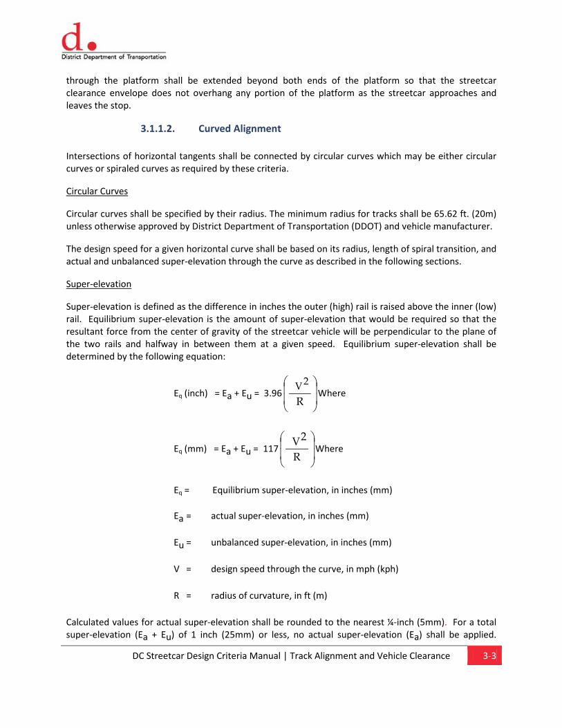
Super-elevation
Super-elevation is defined as the difference in inches the outer (high) rail is raised above the inner (low) rail. Equilibrium super-elevation is the amount of super-elevation that would be required so that the resultant force from the center of gravity of the streetcar vehicle will be perpendicular to the plane of the two rails and halfway in between them at a given speed. Equilibrium super-elevation shall be determined by the following equation:
Eq (inch) = Ea + Eu = 3.96
R
2V Where
Eq (mm) = Ea + Eu = 117
R
2 VWhere
Eq = Equilibrium super-elevation, in inches (mm)
Ea = actual super-elevation, in inches (mm)
Eu = unbalanced super-elevation, in inches (mm)
V = design speed through the curve, in mph (kph)
R = radius of curvature, in ft (m)
Calculated values for actual super-elevation shall be rounded to the nearest ¼-inch (5mm). For a total super-elevation (Ea + Eu) of 1 inch (25mm) or less, no actual super-elevation (Ea) shall be applied.
DC Streetcar Design Criteria Manual | Track Alignment and Vehicle Clearance 3-4
Actual super-elevation (Ea) shall be attained and removed linearly throughout the full length of the spiral transition curve by raising the outside rail while maintaining the inside rail at the profile grade.
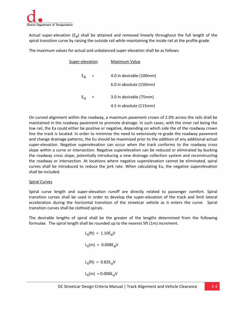
The maximum values for actual and unbalanced super-elevation shall be as follows:
On curved alignment within the roadway, a maximum pavement crown of 2.0% across the rails shall be maintained in the roadway pavement to promote drainage. In such cases, with the inner rail being the low rail, the Ea could either be positive or negative, depending on which side the of the roadway crown line the track is located. In order to minimize the need to extensively re-grade the roadway pavement and change drainage patterns, the Eu should be maximized prior to the addition of any additional actual super-elevation. Negative superelevation can occur when the track conforms to the roadway cross slope within a curve or intersection. Negative superelevation can be reduced or eliminated by bucking the roadway cross slope, potentially introducing a new drainage collection system and reconstructing the roadway or intersection. At locations where negative superelevation cannot be eliminated, spiral curves shall be introduced to reduce the jerk rate. When calculating Eu, the negative superelevation shall be included.
Spiral Curves
Spiral curve length and super-elevation runoff are directly related to passenger comfort. Spiral transition curves shall be used in order to develop the super-elevation of the track and limit lateral acceleration during the horizontal transition of the streetcar vehicle as it enters the curve. Spiral transition curves shall be clothoid spirals.
The desirable lengths of spiral shall be the greater of the lengths determined from the following formulae. The spiral length shall be rounded up to the nearest 5ft (1m) increment.
Ls(ft) = 1.10EaV
Ls(m) = 0.008EaV
Ls(ft) = 0.82EuV
Ls(m) = 0.006EuV
Super-elevation Maximum Value
Ea = 4.0 in desirable (100mm)
6.0 in absolute (150mm)
Eu = 3.0 in desirable (75mm)
4.5 in absolute (115mm)
DC Streetcar Design Criteria Manual | Track Alignment and Vehicle Clearance 3-5
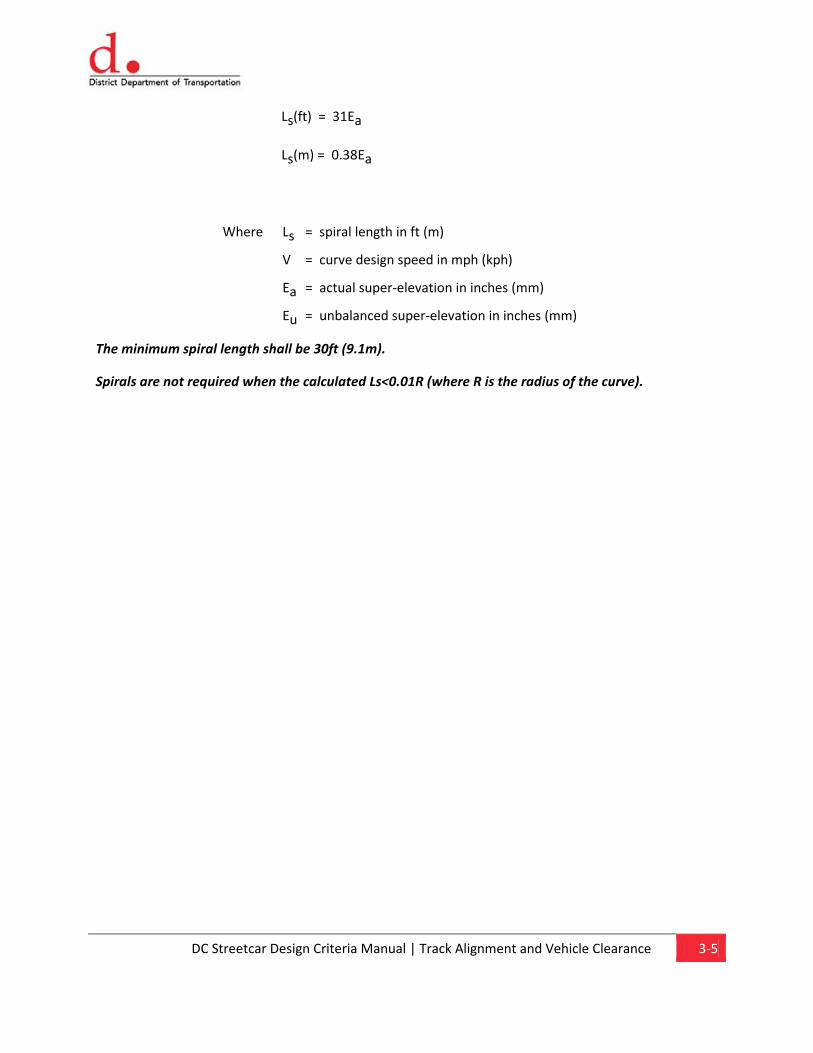
Ls(ft) = 31Ea
Ls(m) = 0.38Ea
Where Ls = spiral length in ft (m)
V = curve design speed in mph (kph)
Ea = actual super-elevation in inches (mm)
Eu = unbalanced super-elevation in inches (mm)
The minimum spiral length shall be 30ft (9.1m).
Spirals are not required when the calculated Ls<0.01R (where R is the radius of the curve).
DC Streetcar Design Criteria Manual | Track Alignment and Vehicle Clearance 3-6
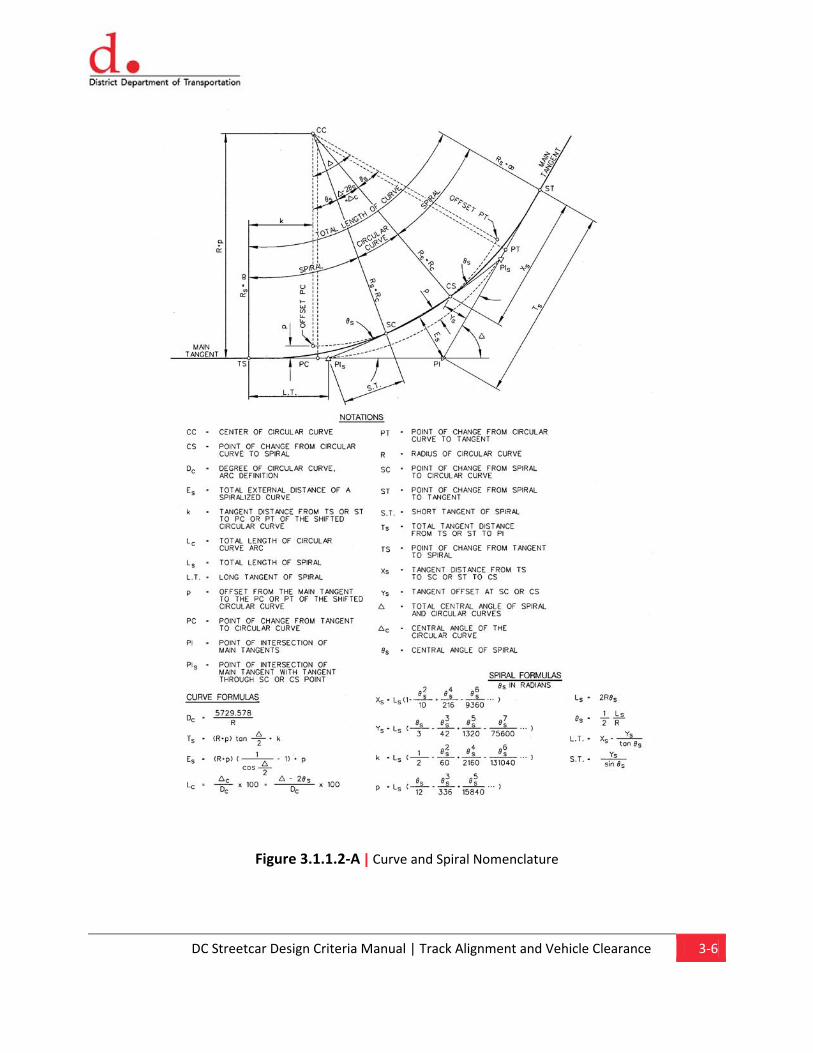
Figure 3.1.1.2-A | Curve and Spiral Nomenclature
DC Streetcar Design Criteria Manual | Track Alignment and Vehicle Clearance 3-7
3.1.1.3. Reverse Curves
Reverse curves shall be avoided on mainline track. Every attempt shall be made to use standard circular curves with tangent sections as described in Section 3.1.1.2. For those sections where reverse curves must be used, the following criteria may be used with prior approval from DDOT.
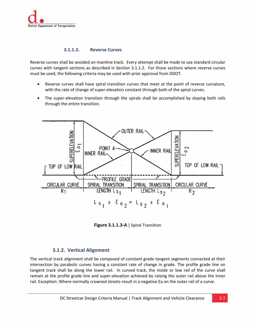
• Reverse curves shall have spiral transition curves that meet at the point of reverse curvature, with the rate of change of super-elevation constant through both of the spiral curves.
• The super-elevation transition through the spirals shall be accomplished by sloping both rails through the entire transition.
Figure 3.1.1.3-A | Spiral Transition
3.1.2. Vertical Alignment
The vertical track alignment shall be composed of constant grade tangent segments connected at their intersection by parabolic curves having a constant rate of change in grade. The profile grade line on tangent track shall be along the lower rail. In curved track, the inside or low rail of the curve shall remain at the profile grade line and super-elevation achieved by raising the outer rail above the inner rail. Exception: Where normally crowned streets result in a negative Ea on the outer rail of a curve.
DC Streetcar Design Criteria Manual | Track Alignment and Vehicle Clearance 3-8
3.1.2.1. Vertical Tangents
The minimum length of constant profile grade between vertical curves shall be as follows:
Condition
Length
Desirable Minimum 33 ft (10m) or 3 times the design speed in mph (kph), whichever is greater
Minimum 0 ft (0m)
The profile at stations shall be on a vertical tangent.
3.1.2.2. Vertical Grades
The following profile grade limitations shall apply:
Primary Track in Mixed-Traffic Lanes on City Streets
When the track occupies the travel lane or adjacent parking lane, the vertical profile should match the roadway profile and associated crown to the extent reasonable and practical without exceeding the project design criteria. When setting initial profiles in roadway areas an assessment shall be made of the amount of adjacent roadway pavement that may need to be reconstructed in any event due to requisite utility relocations. When such areas are considered, it may be found to be both practical and cost-efficient to further optimize the track profile by making minor pavement contour adjustments in the utility work areas.
Mainline tracks
Maximum 7.0% (Desired), 9.0% (Maximum)
Minimum (for drainage) 0.2%
Absolute Minimum* 0.0%
*To match existing roadway profile, special trackwork, and maintenance & operations facility trackage.
Passenger Stop Area
Maximum 5.0% (Desired), 7.0% (Maximum)
Minimum (for drainage) 0.2%
Absolute Minimum* 0.0%
*To match existing roadway profile.
DC Streetcar Design Criteria Manual | Track Alignment and Vehicle Clearance 3-9
Every effort shall be made to maintain a constant grade in station areas.
3.1.2.3. Vertical Curves
All changes in grade shall be connected by vertical curves. Vertical curves shall be defined by parabolic curves having a constant rate of change in grade.
Vertical Curve Lengths
The desired minimum length of vertical curves shall be 50 ft (15 m).
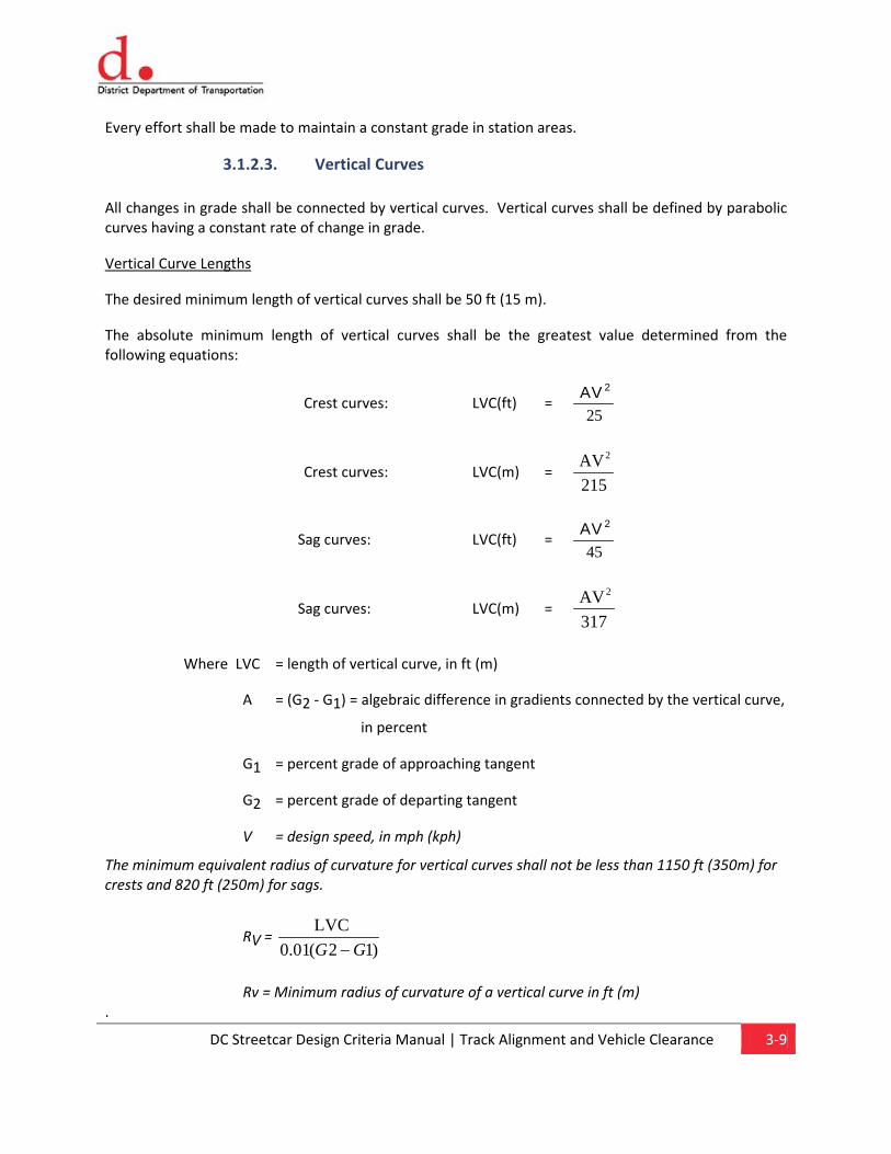
The absolute minimum length of vertical curves shall be the greatest value determined from the following equations:
Crest curves: LVC(ft) = AV 2
25
Crest curves: LVC(m) = 215AV 2
Sag curves: LVC(ft) = AV 2
45
Sag curves: LVC(m) = 317AV 2
Where LVC = length of vertical curve, in ft (m)
A = (G2 - G1) = algebraic difference in gradients connected by the vertical curve,
in percent
G1 = percent grade of approaching tangent
G2 = percent grade of departing tangent
V = design speed, in mph (kph)
The minimum equivalent radius of curvature for vertical curves shall not be less than 1150 ft (350m) for crests and 820 ft (250m) for sags.
RV = )12(01.0
LVC GG −
Rv = Minimum radius of curvature of a vertical curve in ft (m) .
DC Streetcar Design Criteria Manual | Track Alignment and Vehicle Clearance 3-10
3.1.3. Special Trackwork
In general, special trackwork shall be located on track segments that are tangent both horizontally and vertically, including tangent segments in advance of points of switches. For alignment requirements through special trackwork areas, refer to Chapter 9, Trackwork.
3.2. Clearance Requirements
3.2.1. General
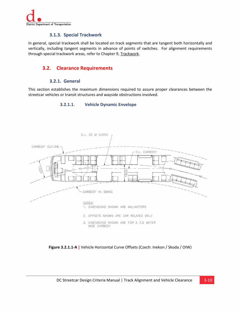
This section establishes the maximum dimensions required to assure proper clearances between the streetcar vehicles or transit structures and wayside obstructions involved.
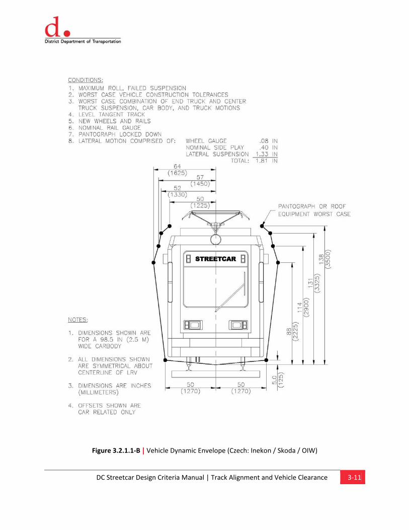
3.2.1.1. Vehicle Dynamic Envelope
Figure 3.2.1.1-A | Vehicle Horizontal Curve Offsets (Czech: Inekon / Skoda / OIW)
DC Streetcar Design Criteria Manual | Track Alignment and Vehicle Clearance 3-11
Figure 3.2.1.1-B | Vehicle Dynamic Envelope (Czech: Inekon / Skoda / OIW)
DC Streetcar Design Criteria Manual | Track Alignment and Vehicle Clearance 3-12
Vehicle Interface at Station Platforms (Czech: Inekon / Skoda / OIW vehicle):
At passenger stations, the distance from the centerline of the track to the edge of platform shall be 4’-2 3/8" (1282mm). The nominal vertical height of the platform on level track shall be 14 inches +/- 1/8” (356mm) for streetcar vehicles without bridge plates. The nominal vertical height of the platform on level track shall be 10 inches +/- 1/8” (254mm) where streetcar vehicles equipped with bridge plates share the platform with busses. The vertical height may need to be adjusted to accommodate the street cross-slope in order to ensure the vehicle-mounted bridging device is deployable under all loading conditions.
As vehicle selection process progresses for the various streetcar routes, the clearance envelopes shall match that described above in order to accommodate already built routes within the District. Design should take into consideration the clearances required provide parking, bike lanes, and delivery vehicles adjacent to the streetcar alignment.
3.2.1.2. Retaining Walls
Where retaining walls are used, they shall comply with the following:
Cut Sections
In those cases where a retaining wall along the streetcar system is in a cut section, the preferred minimum clearance from the centerline of track to the near face of a retaining wall shall be 9 ft 0 in (2.74m) if the retaining wall is higher than the top of rail elevation.
Fill Sections
In retained fill sections, the top of a retaining wall shall be at the same elevation as the top of the adjacent rail (the rail nearest to the wall), and the preferred minimum distance from the centerline of track to any fencing or hand railing on top of the wall shall be a minimum of 9 ft 0 inches (2.74m).
3.2.1.3. Maintenance and Emergency Evacuation Paths
A minimum clear width of 30 inches (0.762m) shall be provided between the Dynamic Envelope and any continuous obstruction (i.e. wall) alongside the track to create a walkway for maintenance personnel and to create a designated passenger emergency evacuation path.
3.2.1.4. Track Spacing
The minimum allowable spacing between two exclusive streetcar mainline tracks, with equal super-elevation and no OCS support poles between them shall be determined from the following formula:
d = Tt + Ta
DC Streetcar Design Criteria Manual | Track Alignment and Vehicle Clearance 3-13
Along sections where OCS poles are located between track centerlines, the minimum track spacing shall be determined from the following formula:
d(inches) = Tt + Ta + 2” + P
d(mm) = Tt + Ta + 50.8mm + P
Where D = Minimum allowable spacing between track centerlines, in inches
(mm)
Tt = dynamic half width of vehicle towards curve center, in inches
(mm)(see appendix 3A for dynamic envelope)
Ta = dynamic half width of vehicle away from curve center, in inches(mm) (see appendix 3A for dynamic envelope)
P = Maximum allowable OCS pole diameter (including deflection) of
18.5 in (470mm)
3.2.1.5. Other Wayside Factors
Other wayside factors (OWF) are additional clearance added to the streetcar dynamic clearance
envelope. These include construction and maintenance tolerances (CMT) and chorded wall construction
factor. Collectively,
OWF = CMT + CW
Construction and maintenance tolerances accounts for the fact that the neither the trackwork nor items
that are constructed alongside of the track can be guaranteed to have been built exactly where
planned. Further, as the system ages, wear and tear may result in movement of some items, further
reducing actual clearances
The tolerances specified in Table 3-1 shall not to be used for construction or maintenance of the system
but rather represent a possible worst case scenario in the event that substandard construction and
maintenance goes undetected and uncorrected.
DC Streetcar Design Criteria Manual | Track Alignment and Vehicle Clearance 3-14
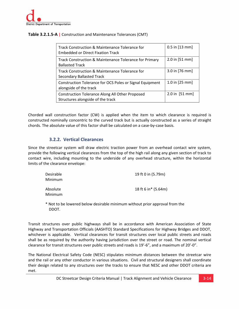
Table 3.2.1.5-A | Construction and Maintenance Tolerances (CMT)
Track Construction & Maintenance Tolerance for Embedded or Direct Fixation Track
0.5 in [13 mm]
Track Construction & Maintenance Tolerance for Primary Ballasted Track
2.0 in [51 mm]
Track Construction & Maintenance Tolerance for Secondary Ballasted Track
3.0 in [76 mm]
Construction Tolerance for OCS Poles or Signal Equipment alongside of the track
1.0 in [25 mm]
Construction Tolerance Along All Other Proposed Structures alongside of the track
2.0 in [51 mm]
Chorded wall construction factor (CW) is applied when the item to which clearance is required is constructed nominally concentric to the curved track but is actually constructed as a series of straight chords. The absolute value of this factor shall be calculated on a case-by-case basis.
3.2.2. Vertical Clearances
Since the streetcar system will draw electric traction power from an overhead contact wire system, provide the following vertical clearances from the top of the high rail along any given section of track to contact wire, including mounting to the underside of any overhead structure, within the horizontal limits of the clearance envelope:
Transit structures over public highways shall be in accordance with American Association of State Highway and Transportation Officials (AASHTO) Standard Specifications for Highway Bridges and DDOT, whichever is applicable. Vertical clearances for transit structures over local public streets and roads shall be as required by the authority having jurisdiction over the street or road. The nominal vertical clearance for transit structures over public streets and roads is 19’-6”, and a maximum of 20’-0”.
The National Electrical Safety Code (NESC) stipulates minimum distances between the streetcar wire and the rail or any other conductor in various situations. Civil and structural designers shall coordinate their design related to any structures over the tracks to ensure that NESC and other DDOT criteria are met.
Desirable Minimum
19 ft 0 in (5.79m)
Absolute Minimum
18 ft 6 in* (5.64m)
* Not to be lowered below desirable minimum without prior approval from the DDOT.
DC Streetcar Design Criteria Manual | Track Alignment and Vehicle Clearance 3-15
Applicable Standard Drawings:
T-01 Standard Track Symbols, Abbreviations & General Notes T-02 Horizontal Curves
Chapter 4Urban Design – Streetcar Stops
Content
4.1. Preferred Siting Criteria 4.2. Streetcar Platforms 4.3. Streetcar Platform Design Parameters 4.4. Streetcar Platform Amenities 4.5. Integration of Public Art
DC Streetcar Design Criteria Manual | Urban Design – Streetcar Stops 4-1
4.0 Urban Design – Streetcar Stops
4.1. Preferred Siting Criteria
4.1.1. Coordination with Plans, Projects, and Adjacent Land Uses
The general locating of streetcar stops shall take into consideration recommendations identified in relevant neighborhood plans and opportunities to complement revitalization projects and supportive land use.
The urban design of the DC Streetcar shall be consistent with:
• DDOT Design Engineering Manual
• DDOT Public Realm Design Handbook
• DC Streetcar Land Use Study
• WMATA Guidelines for the Design and Placement of Transit Stops Platforms.
• Bicycle Interactions and Streetcars Memo
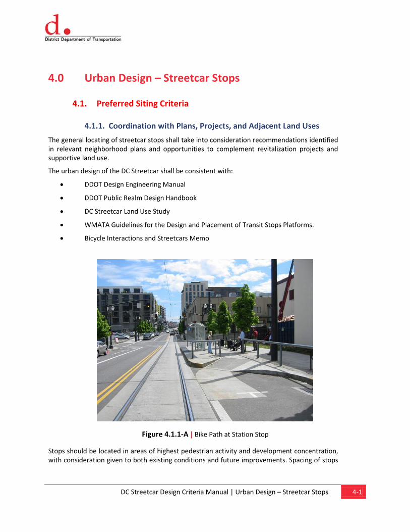
Figure 4.1.1-A | Bike Path at Station Stop
Stops should be located in areas of highest pedestrian activity and development concentration, with consideration given to both existing conditions and future improvements. Spacing of stops
DC Streetcar Design Criteria Manual | Urban Design – Streetcar Stops 4-2
is generally three to four blocks but will vary by corridor and alignment type. The type of platform and stop location to be used will be guided by specific site conditions.
4.2. Streetcar Platforms
4.2.1. Types
There are four types of streetcar platforms that may be used in the DC system: curb extension, curbside, median and pedestrian plaza.
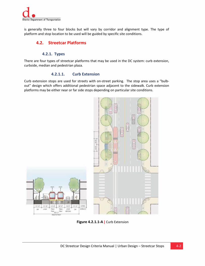
4.2.1.1. Curb Extension
Curb extension stops are used for streets with on-street parking. The stop area uses a “bulb-out” design which offers additional pedestrian space adjacent to the sidewalk. Curb extension platforms may be either near or far side stops depending on particular site conditions.
Figure 4.2.1.1-A | Curb Extension
DC Streetcar Design Criteria Manual | Urban Design – Streetcar Stops 4-3
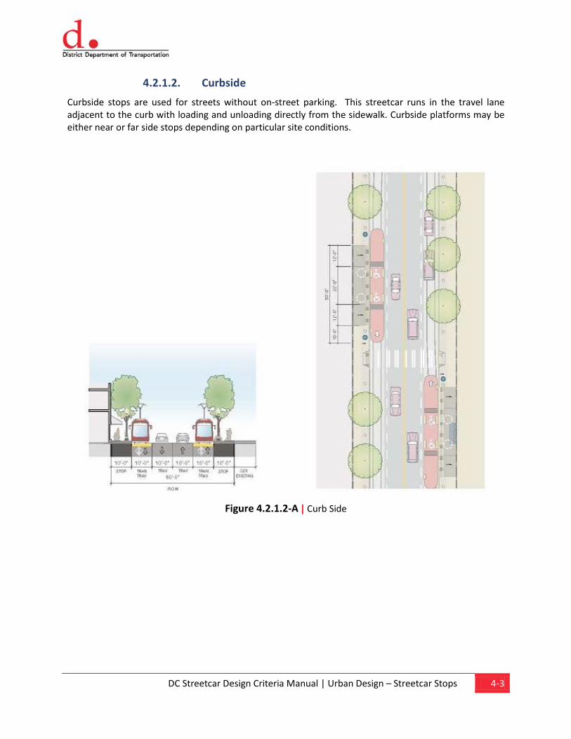
4.2.1.2. Curbside
Curbside stops are used for streets without on-street parking. This streetcar runs in the travel lane adjacent to the curb with loading and unloading directly from the sidewalk. Curbside platforms may be either near or far side stops depending on particular site conditions.
Figure 4.2.1.2-A | Curb Side
DC Streetcar Design Criteria Manual | Urban Design – Streetcar Stops 4-4
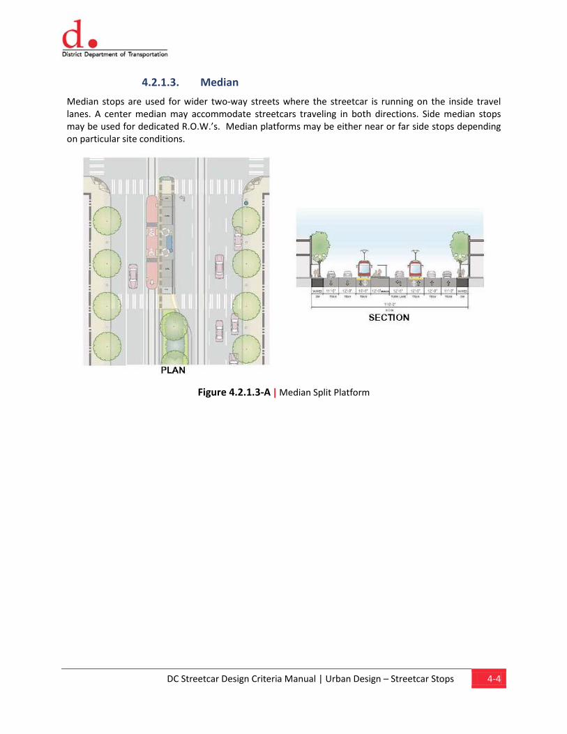
4.2.1.3. Median
Median stops are used for wider two-way streets where the streetcar is running on the inside travel lanes. A center median may accommodate streetcars traveling in both directions. Side median stops may be used for dedicated R.O.W.’s. Median platforms may be either near or far side stops depending on particular site conditions.
Figure 4.2.1.3-A | Median Split Platform
DC Streetcar Design Criteria Manual | Urban Design – Streetcar Stops 4-5
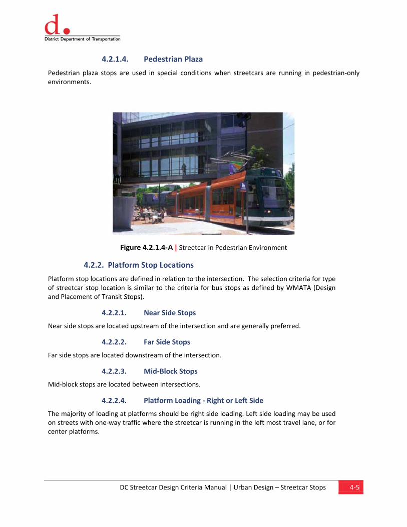
4.2.1.4. Pedestrian Plaza
Pedestrian plaza stops are used in special conditions when streetcars are running in pedestrian-only environments.
Figure 4.2.1.4-A | Streetcar in Pedestrian Environment
4.2.2. Platform Stop Locations
Platform stop locations are defined in relation to the intersection. The selection criteria for type of streetcar stop location is similar to the criteria for bus stops as defined by WMATA (Design and Placement of Transit Stops).
4.2.2.1. Near Side Stops
Near side stops are located upstream of the intersection and are generally preferred.
4.2.2.2. Far Side Stops
Far side stops are located downstream of the intersection.
4.2.2.3. Mid-Block Stops
Mid-block stops are located between intersections.
4.2.2.4. Platform Loading - Right or Left Side
The majority of loading at platforms should be right side loading. Left side loading may be used on streets with one-way traffic where the streetcar is running in the left most travel lane, or for center platforms.
DC Streetcar Design Criteria Manual | Urban Design – Streetcar Stops 4-6
4.2.3. Coordination with Bus Stops – Lengths, Shared Loading
To provide convenient transfers, the streetcar platforms should be designed to accommodate bus loading. The configuration of the platform for low-floor vehicles should provide access to the front and middle doors of 40’ standard and 66’ articulated buses.
4.3. Streetcar Platform Design Parameters
To be provided in DC Streetcar Standard Drawings.
4.3.1. Lengths
To accommodate the double articulated, 66’ low floor streetcar vehicle, the platform length for one vehicle is generally 60’ to 70’ long.
4.3.2. Loading Areas – ADA and Non-ADA
There are two loading areas on the platform – the leading edge of the platform accommodates access to the front door of the vehicle (on left side platforms, the rear door) and the middle section of the platform provides ADA-compliant access.
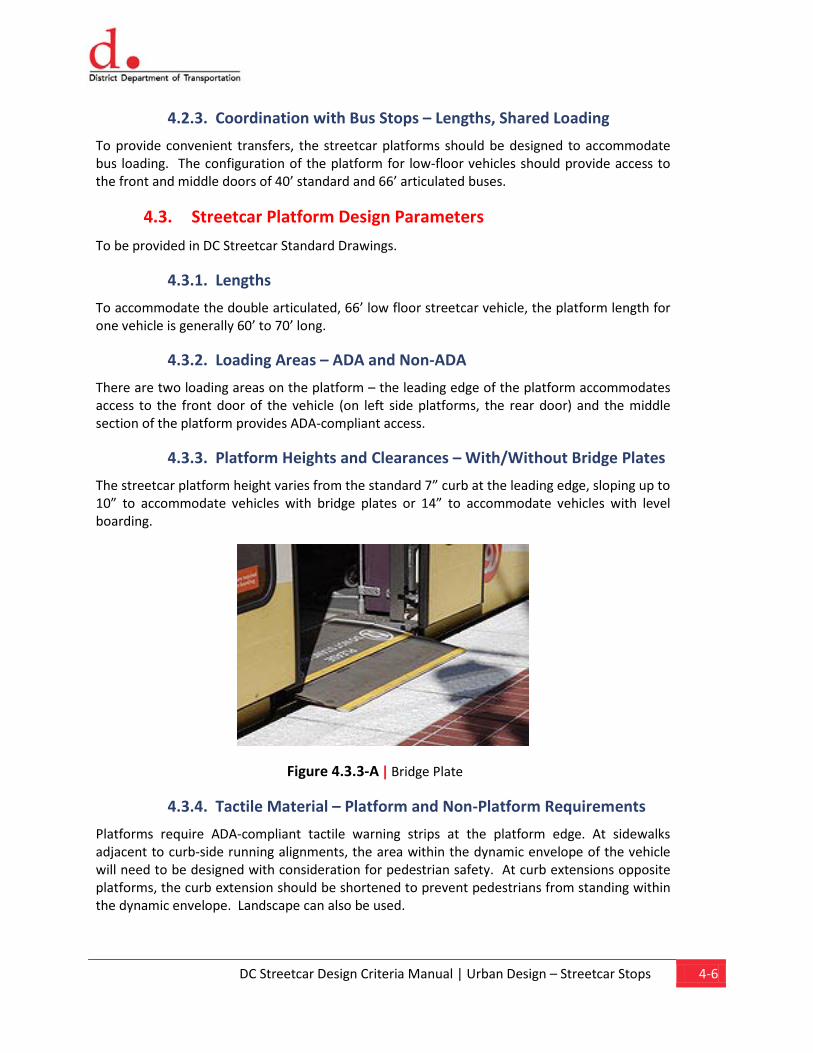
4.3.3. Platform Heights and Clearances – With/Without Bridge Plates
The streetcar platform height varies from the standard 7” curb at the leading edge, sloping up to 10” to accommodate vehicles with bridge plates or 14” to accommodate vehicles with level boarding.
Figure 4.3.3-A | Bridge Plate
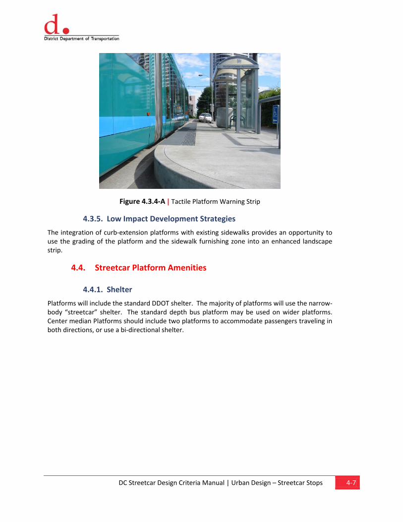
4.3.4. Tactile Material – Platform and Non-Platform Requirements
Platforms require ADA-compliant tactile warning strips at the platform edge. At sidewalks adjacent to curb-side running alignments, the area within the dynamic envelope of the vehicle will need to be designed with consideration for pedestrian safety. At curb extensions opposite platforms, the curb extension should be shortened to prevent pedestrians from standing within the dynamic envelope. Landscape can also be used.
DC Streetcar Design Criteria Manual | Urban Design – Streetcar Stops 4-7
Figure 4.3.4-A | Tactile Platform Warning Strip
4.3.5. Low Impact Development Strategies
The integration of curb-extension platforms with existing sidewalks provides an opportunity to use the grading of the platform and the sidewalk furnishing zone into an enhanced landscape strip.
4.4. Streetcar Platform Amenities
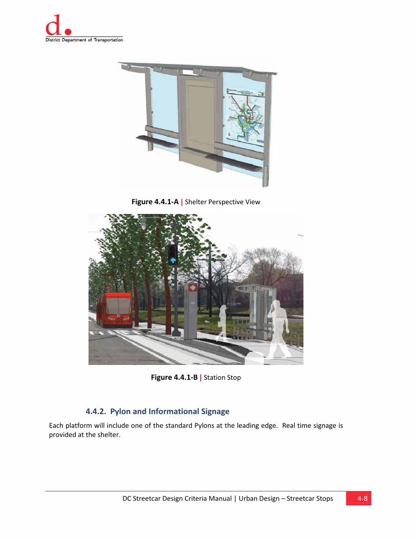
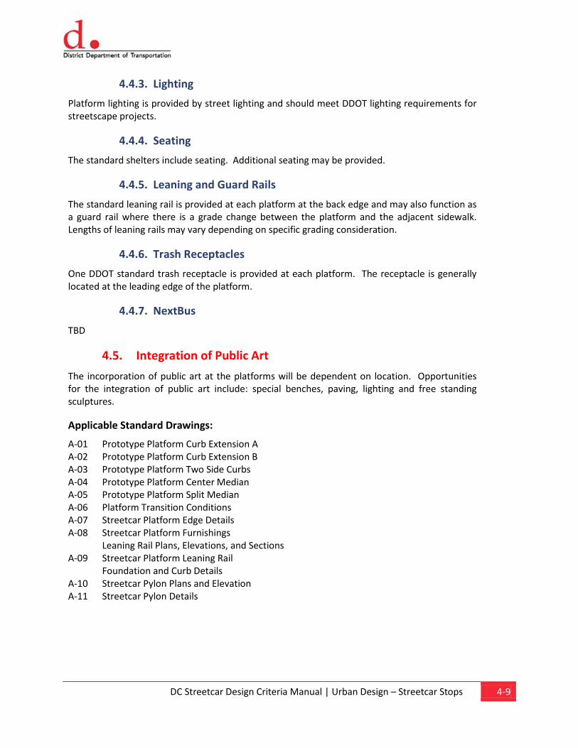
4.4.1. Shelter
Platforms will include the standard DDOT shelter. The majority of platforms will use the narrow-body “streetcar” shelter. The standard depth bus platform may be used on wider platforms. Center median Platforms should include two platforms to accommodate passengers traveling in both directions, or use a bi-directional shelter.
DC Streetcar Design Criteria Manual | Urban Design – Streetcar Stops 4-8
Figure 4.4.1-A | Shelter Perspective View
Figure 4.4.1-B | Station Stop
4.4.2. Pylon and Informational Signage
Each platform will include one of the standard Pylons at the leading edge. Real time signage is provided at the shelter.
DC Streetcar Design Criteria Manual | Urban Design – Streetcar Stops 4-9
4.4.3. Lighting
Platform lighting is provided by street lighting and should meet DDOT lighting requirements for streetscape projects.
4.4.4. Seating
The standard shelters include seating. Additional seating may be provided.
4.4.5. Leaning and Guard Rails
The standard leaning rail is provided at each platform at the back edge and may also function as a guard rail where there is a grade change between the platform and the adjacent sidewalk. Lengths of leaning rails may vary depending on specific grading consideration.
4.4.6. Trash Receptacles
One DDOT standard trash receptacle is provided at each platform. The receptacle is generally located at the leading edge of the platform.
4.4.7. NextBus
TBD
4.5. Integration of Public Art
The incorporation of public art at the platforms will be dependent on location. Opportunities for the integration of public art include: special benches, paving, lighting and free standing sculptures.
Applicable Standard Drawings:
A-01 Prototype Platform Curb Extension A A-02 Prototype Platform Curb Extension B A-03 Prototype Platform Two Side Curbs A-04 Prototype Platform Center Median A-05 Prototype Platform Split Median A-06 Platform Transition Conditions A-07 Streetcar Platform Edge Details A-08 Streetcar Platform Furnishings
Leaning Rail Plans, Elevations, and Sections A-09 Streetcar Platform Leaning Rail
Foundation and Curb Details A-10 Streetcar Pylon Plans and Elevation A-11 Streetcar Pylon Details
Chapter 5 Civil Work
Content
5.1. Survey Control System 5.2. Drainage 5.3. Right-of-Way 5.4. Roadways 5.5. Grading
DC Streetcar Design Criteria Manual | Civil Work 5-1
5.0 Civil Work This chapter establishes the basic civil engineering criteria to be used in the design of the DC Streetcar Program. It includes criteria for surveys and the design of drainage, roadways/paving, and determination of required rights-of-way.
5.1. Survey Control System
5.1.1. Horizontal Control
All horizontal controls for this project shall be based on survey control points established under the direction of the District Department of Transportation (DDOT). Coordinates for project control points established for the system shall be based on the Maryland State Plane Coordinate System. The North American Datum of 1983 (NAD83), 1990 or later readjustment shall be used to establish horizontal control.
The accuracy of the horizontal ground control and of supporting ground control surveys shall as a minimum be Second Order, Class I, as defined by the Federal Geodetic Control Committee and published under the title “Classification, Standards of Accuracy and General Specifications of Geodetic Control Stations, published by the National Geodetic Survey (NGS)“ in February 1974.
5.1.2. Vertical Control
The vertical control for this project shall be based on the North American Vertical Datum of 1988 (NAVD88).
The accuracy of the vertical ground control and of supporting vertical ground control surveys shall be at least Second Order, Class I, as defined in the preceding section.
5.2. Drainage
The goal in the design of system drainage is to protect the track and facilities from storm water-runoff damage, provide proper drainage of the shared use roadway, and to minimize potential impacts to properties along the alignment from resulting storm water-runoff, either passing through or caused by streetcar construction, while maintaining consistency with the requirements of the Clean Water Act. The District Department of the Environment (DDOE) has jurisdiction over the stormwater quality criteria for this project.
The design of drainage facilities shall be in accordance with:
• District Department of Transportation 2009 “Design and Engineering Manual”
• WMATA, Tram-LRT Guidelines
• DC Water and Sewer Authority “Standard Details and Guidelines”
• DC Water and Sewer Authority “Specifications”
DC Streetcar Design Criteria Manual | Civil Work 5-2
• District Department of the Environment “Stormwater Guidebook”
5.2.1. Roadway Drainage
Roadway Drainage will be designed according to the DDOT Design and Engineering Manual (Chapter 33) to accommodate the storm water discharge based on a 15-year / 24-hour design storm, which shall be used for urban streets, and a 25-year / 24-hour design storm, which shall be used for interstate systems to ensure that adequate flood protection is provided. For storm sewer pipes, a 50-year storm for pipes draining low point in sag shall be used. Maximum spacing of inlets on streets shall be the length of the block. Maximum spacing for manholes shall be 400 feet. The design discharge should be calculated using the Rational Method.
The DC Water and Sewer Authority (DC Water) Standard Details, Guidelines and Specifications, shall be used for all proposed drainage facilities.
In addition, the DDOE “Stormwater Guidebook” states the runoff depth to be treated on post-development land use for water quality treatment on transportation projects. DDOE requires that all projects meet the district water quality standards, as set forth in Chapters 1-5, “Stormwater Guidebook”. To ensure that these criteria are met, the Project must also meet the quantity control requirements, as described in the guidebook. It also requires that all projects meet the minimum control requirements for stormwater management and the selection of the most effective BMP system.
5.2.2. Streetcar/Track Drainage Streetcar/Track drainage guidelines apply only to design of drainage facilities under the jurisdiction of WMATA. Drainage of roadway facilities and connections to other drainage systems will be designed in accordance with the criteria of DDOT and DC Water.
Streetcar/Track facilities will be designed to accommodate the storm water discharge based on the 25-year storm frequency for track roadbed, longitudinal storm drains in roadways, all longitudinal drains or subdrains at low points, and 100-year for all culverts and drainage facilities crossing the streetcar/track.
In track sections, manholes or drainage inlets will be provided at maximum spacing for the selected type based on pipe cleaning requirements (300 feet maximum) or the restricting water depth encroachment from the tracks, whichever is less.
Designs of drainage facilities belonging to any other agencies, which are relocated or modified because of streetcar construction and which do not cross or parallel streetcar system guideway or facilities, shall conform to the design criteria and standards of the agency or jurisdiction involved.
5.3. Right-Of-Way
Right-of-way is the composite total requirement of all real property, interests and uses, both temporary and permanent, needed to construct, maintain, protect and operate the DC Streetcar. The intent is to acquire and maintain the minimum right-of-way required consistent with the requirements of the DC Streetcar Program.
DC Streetcar Design Criteria Manual | Civil Work 5-3
The taking envelope is influenced by the existing topography, drainage, service roads, utilities, the nature of the streetcar structures selected, and disaster and/or fire fighting requirements.
Where property must be acquired to provide right-of-way for the DC Streetcar Program, such property acquisition shall be done in conformance with all appropriate city, state and federal regulations.
5.3.1. Definition of Types of Right-of-Way
Rights-of-way may consist of anyone or combination of several types of real property interests. There are Fee Ownership, Joint Use of Public Right-of-Way, Permanent Easement, Construction Easement and Utility Easement.
5.3.1.1. Fee Ownership/Exclusive Right-of-Way
Fee ownership is a condition where ownership of property is purchased for project related facilities and the right-of-way is used exclusively by the DC Streetcar.
5.3.1.2. Joint Use of Public Right-of-Way
Joint use of public right-of-way is a condition in which the DC Streetcar facilities would be constructed in the public right-of-way. Existing and future facilities such as sidewalks, gas lines, water lines, sewers and others not necessarily related to the DC Streetcar Program could also be contained in a portion of the same public right-of-way. Joint use of public right-of-way shall always be the first type of right-of-way considered for the DC Streetcar Program.
5.3.1.3. Permanent Easement
Permanent easement right-of-way is a condition in which ownership of the property is held in Fee by others and an easement or right to occupy a certain limited portion of the property, usually for a specified use, is acquired from the Fee owner.
5.3.1.4. Construction Easement
Construction easement right-of-way is a condition in which a temporary easement or short-term lease is acquired from the Fee owner. A construction easement provides sufficient space to allow for the use of the property by the contractor during construction. This easement usually terminates soon after the completion of construction.
5.3.1.5. Utility Easement
Utility easement right-of-way is a condition in which ownership of the property is held in Fee by others and an easement or right to install and maintain utilities, either underground or overhead, on a certain limited portion of the property, is acquired from the Fee owner.
5.4. Roadways
Roadway design in public rights-of-way shall be in conformance with the specifications and design guidelines of DDOT. The structural cross section of the streetcar pavement shall be designed for a 20-year life to support the anticipated traffic use.
DC Streetcar Design Criteria Manual | Civil Work 5-4
Road and parking surfaces shall be either Portland cement concrete pavement or Plant-Mix Bituminous Pavement. The criteria set forth in this section are applicable to the design or alterations to existing streets.
5.4.1. Applicable Standards
Unless otherwise stated, roadway design shall be in accordance with the Codes and Standards described in Chapter 1, General
The current versions of the following documents are also incorporated into these design criteria by reference and they should be adhered to wherever possible in the design of roads and parking and related traffic control. In cases where DDOT design standards conflict with other published standards, the DDOT design standards shall govern.
. Those designs shall be in conformance with the current version of published standards and details of the local agency having jurisdiction.
• District Department of Transportation (DDOT) “Design and Engineering Manual”
• DDOT “Standards Specifications for Highway and Structures”
• DDOT “Standard Drawings”
• AASHTO Guide for Pavement Design
• ADA Standards for Accessible Design
• DDOT Bicycle Facility Design Guide
• DDOT Policy and Procedures for School and Pedestrian Safety
• Manual of Uniform Traffic Control Devices
• Policy on Geometric Design of Highways and Streets (AASHTO)
• Roadway Design Guide (AASHTO)
5.4.2. Roadway Geometrics
Design of District of Columbia roadways shall be in accordance with a Policy on Geometric Design of Highways and Streets, latest edition of the American Association of State Highway and Transportation Officials (AASHTO), requirements listed in Chapter 1, General
5.4.2.1. Traffic Lane Widths
, and as listed above.
City streets shall have 10’-0” (minimum) traffic lane widths unless otherwise authorized in writing by DDOT. Designated streetcar traffic lanes shall be 11’-0” (minimum) unless modified as necessary while still maintaining the minimum dynamic envelope of the streetcar vehicle.
Roads shall be in accordance with DDOT Standards and Specifications and “Design and Engineering Manual-Chapter 30.”
DC Streetcar Design Criteria Manual | Civil Work 5-5
In cases of significant constraint, a width reduction may be specified with the approval of DDOT.
5.4.2.2. Number of Traffic Lanes
The number of traffic lanes and type of lanes (i.e., through, right or left) shall be determined in consultation with DDOT, generally based on a traffic analysis which considers projected traffic volumes, streetcar vehicles intersection crossings, critical traffic movements, and geometric configurations. Wherever possible the existing traffic lanes shall be maintained as currently used and only modified as approved by DDOT.
5.4.2.3. Parking Lanes
Parking lane locations shall be determined in consultation with DDOT based on traffic analysis, safety considerations and demand for on-street parking. Twenty-four hour parking prohibition shall be recommended at those locations (i.e., near intersections and at streetcar stations) where roadway width is not adequate to provide the necessary number of through lanes. Peak hour parking prohibition shall be recommended at those locations where traffic analysis shows that the capacity of the traveled way without the parking lane will not provide the level of service required. Parking lane widths shall be 9’-0” minimum adjacent to the streetcar lane, and striped to delineate the limits of the streetcar dynamic envelope.
A stop location along a street with on-street parking is created by extending the sidewalk edge out to meet the travel lane (a bulb-out), which may result in the elimination of parking spaces, loading zones, etc. (as approved by DDOT).
5.4.2.4. Vertical Clearance
The minimum vertical clearance above the traffic lanes and shoulders on all roadways shall be 19 feet. Clearance above the roadway when approaching or passing under an existing structure may be reduced, as compatible with the vehicles pantograph, with approval of DDOT. The clearance shall apply over the entire vehicle roadway width including any contiguous auxiliary (turning) lanes and shoulders. Traffic signals, mast arms and pedestrian bridges shall be relocated or modified as necessary to provide adequate clearance for the streetcar’s catenary power system.
Vertical clearances associated with railroad crossings shall be in accordance with affected agency requirements.
5.4.3. Curbs, Wheelchair Ramps and Curb Cuts
Concrete curbs shall be installed along all new, widened or reconstructed streets or access roads to be owned or maintained by DDOT. Existing granite curbs shall be replaced or restored in kind, and limestone curb shall be replaced with granite or concrete as directed by DDOT.
When new curb is constructed, the height of the face of curb above the finished pavement elevation shall be in accordance with DDOT standards. At station platforms, a raised curb line allows for ADA access to/from the streetcar. The raised curb shall be accomplished through ramps or slopes with the existing sidewalk, curb or other.
DC Streetcar Design Criteria Manual | Civil Work 5-6
Where the streetcar operates along a travel lane adjacent to on-street parking, a stop location is created by extending the sidewalk edge and curb line out to meet the travel lane (a bulb-out), eliminating three or four parking spaces.
Wheelchair ramps with curb cuts shall be provided in accordance with the following:
• Restore or replace any existing ramps
• Where alleys are encountered (with or without curb ramps) accessibility shall be handled by building the alley entrances as Modified Commercial Driveways – not with the use of standard curb ramps. The curb radius will generally be 4’, but may vary depending on the width of the crossing sidewalk.
• Provide new ramps at intersections where sidewalk exists and the curb returns are modified as part of this project. It is not necessary to provide ramps and curb cuts where no sidewalk exists, unless the ramp is located at an intersection where no ramp exists.
• Provide ramps and curb cuts at intersections or mid-block locations where new curb and sidewalk will be constructed as part of this project
The design and location of curb cuts and ramps shall be in accordance with the applicable provisions of DDOT and USDOT's Standards for Accessible Transportation Facilities to comply with the Americans with Disabilities Act (ADA).
5.4.4. Sidewalks
Sidewalks shall comply with DDOT Standards and Specifications. Cross slopes on sidewalks shall desirably be two percent. Existing sidewalks impacted by the project shall be repaired or replaced in kind where practical. New sidewalks may be required at station stops.
At station stops, the minimum requirements for having a sidewalk in front of the station shelter is 3 ft from the edge of the detectable warning strip with a 5 ft width being preferred. Access ramps for a stop with sidewalk behind the shelter would require some extra sidewalk to allow for maneuverability between the ramps and the sidewalk.
5.4.5. Driveways
Driveway pavement types and minimum widths shall be as per DDOT standards. In general, all existing driveways impacted by the project shall be replaced in kind, where practical. Driveway closings required to facilitate streetcar operations or construction must be approved by DDOT.
5.4.6. Roadway Paving
Restored or widened city streets shall be designed in accordance with DDOT Standards and Specifications.
Travel lanes, drop-off lanes, access drives, stop bars, bike lanes and selected crosswalks shall be designated with striping as per DDOT standards.
Significant re-grading may be required at intersections, particularly at the turns, in order to deal with variable crowns. Drainage must be maintained, with particular attention given to curb ramps.
DC Streetcar Design Criteria Manual | Civil Work 5-7
5.4.7. Traffic Maintenance and Protection
The design drawings shall be in accordance with the Manual of Uniform Traffic Control Devices (MUTCD) and the requirements of DDOT-Temporary Traffic Control Manual Guidelines and Standards. The design shall include traffic staging and detour plans submitted to and approved by local agencies. The maintenance and protection of both vehicular and pedestrian traffic must be addressed on the plans.
Construction of railroad crossings shall be completed in one continuous work period timed to minimize delays on tracks. Approval of construction plans and construction sequence are required by the railroad company. An agreement between DDOT and the railroad company may be required.
Pedestrian traffic shall be maintained where it is possible to do so safely. The designer shall include any site-specific requirements in the design drawings. Maintenance of pedestrian traffic shall be in accordance with the ADA, MUTCD, and DDOT standards, as appropriate.
5.5. Grading
All unpaved areas of proposed construction will be cleared and grubbed, including the removal of unsuitable backfill material and root mat. All areas disturbed by construction will be protected by an approved erosion and sediment control system as per the District Department of the Environment (DDOE) Standards and Specifications for Soil Erosion and Sediment Control. Methods of erosion control to be considered may include seeding and mulching, sodding, application of geotextile fabrics to stabilize areas, and the application of a gravel or coarse rock blanket.
Cut and fill slopes along the Streetcar/Track will be two horizontal to one vertical (2:1), or as otherwise determined by geotechnical analysis. Along roadway areas, cut slopes will generally be 2:1 maximum or flatter as required for sight distance around curved alignments. Roadway fill slopes will be 2:1 maximum, but will be flattened to 4:1 where possible to minimize the need for guide rail.
Applicable Standard Drawings:
C-01 Streetcar Typical Pavement Marking With Dedicated Bike Lane
C-02 Streetcar Typical Traffic Signing With Dedicated Bike Lane
C-03 Streetcar Typical Pavement Marking With Shared Bike Lane (2 Travel Lanes)
C-04 Streetcar Typical Traffic Signing With Shared Bike Lane (2 Travel Lanes)
C-05 Streetcar Typical Pavement Marking With Shared Bike Lane (3 Travel Lanes)
C-06 Streetcar Typical Traffic Signing With Shared Bike Lane (3 Travel Lanes)
Chapter 6Urban Design – Potential R.O.W. and
Alignment Improvements
Content
6.1. Goals and Criteria for Integrating Related Improvements
6.2. Streetscape and Low Impact Development Strategies
6.3. Trackway Design Goals 6.4. Infrastructure
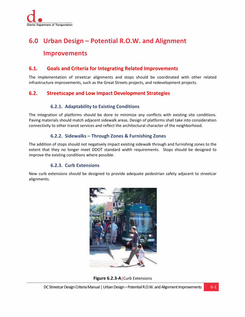
DC Streetcar Design Criteria Manual | Urban Design – Potential R.O.W. and Alignment Improvements 6-1
6.0 Urban Design – Potential R.O.W. and Alignment
Improvements
6.1. Goals and Criteria for Integrating Related Improvements
The implementation of streetcar alignments and stops should be coordinated with other related infrastructure improvements, such as the Great Streets projects, and redevelopment projects.
6.2. Streetscape and Low Impact Development Strategies
6.2.1. Adaptability to Existing Conditions
The integration of platforms should be done to minimize any conflicts with existing site conditions. Paving materials should match adjacent sidewalk areas. Design of platforms shall take into consideration connectivity to other transit services and reflect the architectural character of the neighborhood.
6.2.2. Sidewalks – Through Zones & Furnishing Zones
The addition of stops should not negatively impact existing sidewalk through and furnishing zones to the extent that they no longer meet DDOT standard width requirements. Stops should be designed to improve the existing conditions where possible.
6.2.3. Curb Extensions
New curb extensions should be designed to provide adequate pedestrian safety adjacent to streetcar alignments.
Figure 6.2.3-A|Curb Extensions
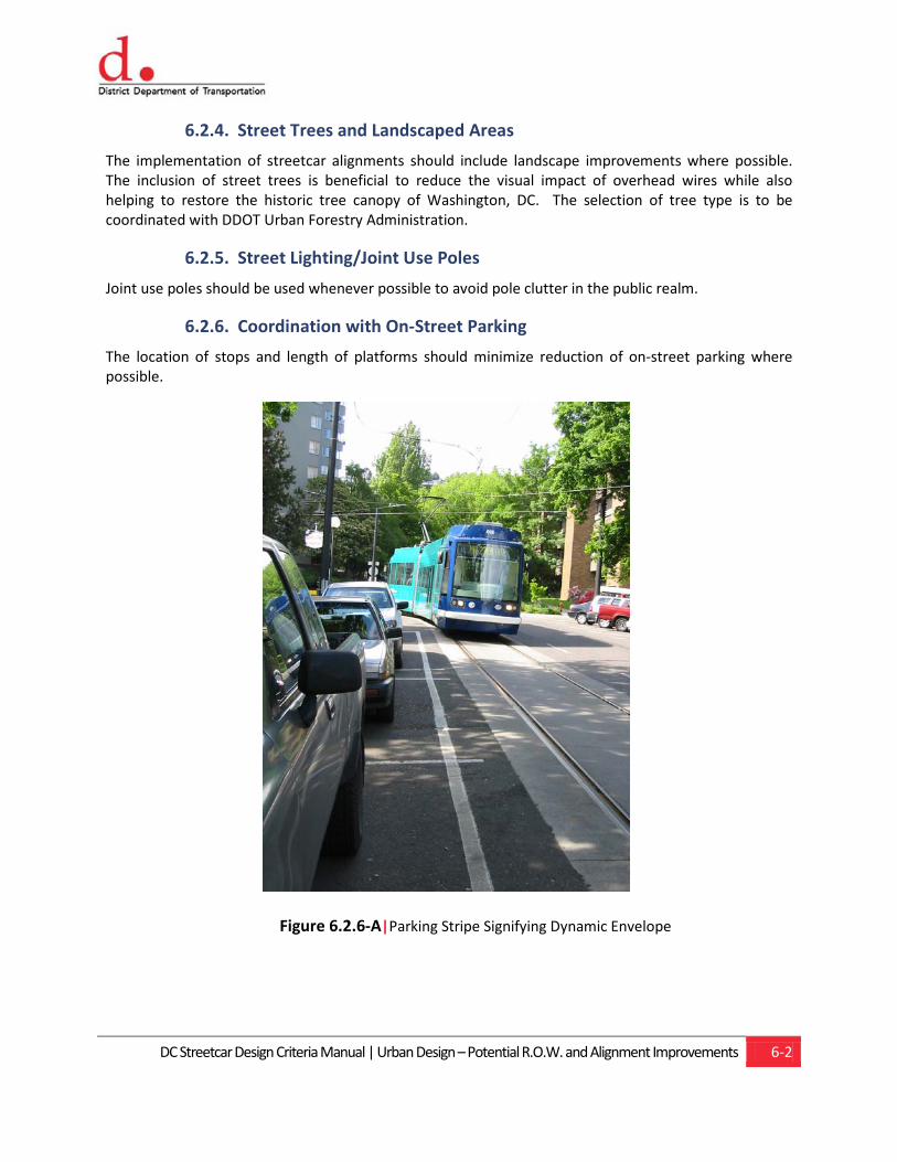
DC Streetcar Design Criteria Manual | Urban Design – Potential R.O.W. and Alignment Improvements 6-2
6.2.4. Street Trees and Landscaped Areas
The implementation of streetcar alignments should include landscape improvements where possible. The inclusion of street trees is beneficial to reduce the visual impact of overhead wires while also helping to restore the historic tree canopy of Washington, DC. The selection of tree type is to be coordinated with DDOT Urban Forestry Administration.
6.2.5. Street Lighting/Joint Use Poles
Joint use poles should be used whenever possible to avoid pole clutter in the public realm.
6.2.6. Coordination with On-Street Parking
The location of stops and length of platforms should minimize reduction of on-street parking where possible.
Figure 6.2.6-A|Parking Stripe Signifying Dynamic Envelope
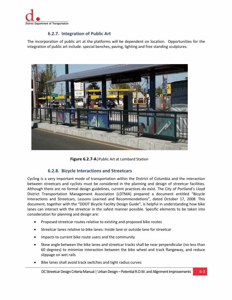
DC Streetcar Design Criteria Manual | Urban Design – Potential R.O.W. and Alignment Improvements 6-3
6.2.7. Integration of Public Art
The incorporation of public art at the platforms will be dependent on location. Opportunities for the integration of public art include: special benches, paving, lighting and free standing sculptures.
Figure 6.2.7-A|Public Art at Lombard Station
6.2.8. Bicycle Interactions and Streetcars
Cycling is a very important mode of transportation within the District of Columbia and the interaction between streetcars and cyclists must be considered in the planning and design of streetcar facilities. Although there are no formal design guidelines, current practices do exist. The City of Portland’s Lloyd District Transportation Management Association (LDTMA) prepared a document entitled “Bicycle Interactions and Streetcars, Lessons Learned and Recommendations”, dated October 17, 2008. This document, together with the “DDOT Bicycle Facility Design Guide”, is helpful in understanding how bike lanes can interact with the streetcar in the safest manner possible. Specific elements to be taken into consideration for planning and design are:
• Proposed streetcar routes relative to existing and proposed bike routes
• Streetcar lanes relative to bike lanes: Inside lane or outside lane for streetcar
• Impacts to current bike route users and the community
• Skew angle between the bike lanes and streetcar tracks shall be near perpendicular (no less than 60 degrees) to minimize interaction between the bike wheel and track flangeway, and reduce slippage on wet rails
• Bike lanes shall avoid track switches and tight radius curves
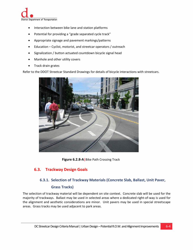
DC Streetcar Design Criteria Manual | Urban Design – Potential R.O.W. and Alignment Improvements 6-4
• Interaction between bike lane and station platforms
• Potential for providing a “grade separated cycle track”
• Appropriate signage and pavement markings/patterns
• Education – Cyclist, motorist, and streetcar operators / outreach
• Signalization / button actuated countdown bicycle signal head
• Manhole and other utility covers
• Track drain grates
Refer to the DDOT Streetcar Standard Drawings for details of bicycle interactions with streetcars.
Figure 6.2.8-A|Bike Path Crossing Track
6.3. Trackway Design Goals
6.3.1. Selection of Trackway Materials (Concrete Slab, Ballast, Unit Paver,
Grass Tracks)
The selection of trackway material will be dependent on site context. Concrete slab will be used for the majority of trackways. Ballast may be used in selected areas where a dedicated right-of-way is used for the alignment and aesthetic considerations are minor. Unit pavers may be used in special streetscape areas. Grass tracks may be used adjacent to park areas.
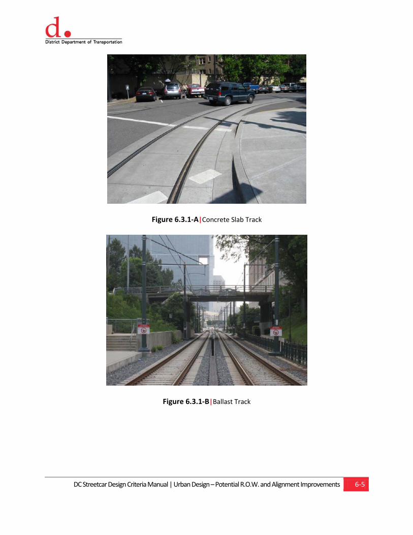
DC Streetcar Design Criteria Manual | Urban Design – Potential R.O.W. and Alignment Improvements 6-5
Figure 6.3.1-A|Concrete Slab Track
Figure 6.3.1-B|Ballast Track
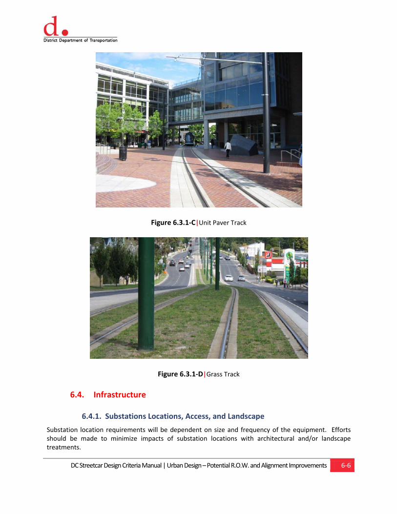
DC Streetcar Design Criteria Manual | Urban Design – Potential R.O.W. and Alignment Improvements 6-6
Figure 6.3.1-C|Unit Paver Track
Figure 6.3.1-D|Grass Track
6.4. Infrastructure
6.4.1. Substations Locations, Access, and Landscape
Substation location requirements will be dependent on size and frequency of the equipment. Efforts should be made to minimize impacts of substation locations with architectural and/or landscape treatments.
Chapter 7 Utilities
Content
7.1. Preconstruction 7.2. Gas Lines 7.3. Sanitary, Storm and Water 7.4. Electrical Power Facilities 7.5. Telephone, Fiber Optic, Long Distance
and Cable TV Facilities 7.6. Street Lights and Traffic Signals 7.7. Parking Meters and Pay & Display
Kiosks 7.8. Vaults and Basement Encroachments 7.9. Overhead Utility Lines 7.10. Utility Design Drawings 7.11. Temporary Support of Track Slab for
Utility Maintenance and Replacement

DC Streetcar Design Criteria Manual | Utilities 7-1
7.0 Utilities These criteria shall govern planning, maintenance, support, restoration, abandonment, reconstruction, removal and construction of utilities encountered or impacted by construction of the streetcar system. Utilities design criteria shall be coordinated, and in compliance with, the requirements of the municipalities, utility owners, and the applicable codes, regulations, and policies as established by the District of Columbia Building Code, District Department of Transportation, Utility Policy and Procedure Manual, and all other codes and standards referenced in Chapter 1, General. Efforts shall be made to design the streetcar alignment and ancillary elements such that they minimize impacts to existing utilities without jeopardizing the functionality of the streetcar project.
The following are some of the public and private utility companies to be affected by the construction of the DC Streetcar Program:
Table 7.1-A |Streetcar Utility Company Impacts
STREETCAR UTILITY
No. Utility Company Telephone
1 DC Water & Sewer Authority 202-698-3600 Watermains
1-800-257-7777 Sewers
2 Potomac Electric Power Co. 202-388-2572
3 Verizon 301-282-7031
4 Washington Gas 703-750-4745
5 Comcast 202-635-5533
7.1. Preconstruction
7.1.1. Purpose
The objective of preconstruction activities is to ensure that pertinent utility information is obtained, properly incorporated into the design process, and shown on construction plans. Information shall include owner, type, size, material, location, and existing right-of-way (ROW) of all existing and proposed utility facilities impacted by the DC Streetcar construction, and the disposition of existing and
DC Streetcar Design Criteria Manual | Utilities 7-2
proposed facilities within the area of any land to be acquired by the District Department of Transportation (DDOT).
It is anticipated that the DC Streetcar track facilities will be in conflict with underground and above ground utilities at a number of locations along the proposed route. Access to utilities that require constant inspections and maintenance should not be located within the streetcar vehicle dynamic envelope. Downtime for streetcar operations while utilities are excavated and repaired, in some instances, would not be an acceptable option. Therefore, wherever utility relocations are physically and/or economically feasible, it shall be modified or relocated to locations outside the streetcar clearance envelope.
The following information shall be clearly and correctly identified on the final construction drawings:
• Utilities supported and maintained during construction and continued in service following construction of the DC Streetcar system
• Utilities reconstructed or relocated, supported and maintained in place
• Utilities temporarily relocated and maintained, then restored in original location upon completion of the streetcar system
• Utilities permanently relocated beyond the immediate limits of streetcar construction
• Utilities that have been abandoned, or are to be abandoned and removed
• Existing utility ROW and properties to be acquired for their relocation, if any
• Locations of utility casings crossing the track slab
• Utilities not to be removed
Existing utility service shall not be interrupted and, if temporarily relocated, shall be restored upon completion of work. Replacements for existing sewers or water mains shall be designed to provide service equal to that offered by the existing installations. Designers shall submit any proposal for betterment to the attention of DDOT in the early stages of design. For the purposes of this design criteria document, “utility betterment” shall be defined as the incremental additional cost of a utility relocation over and above the cost of a standard in-kind utility replacement (e.g. increase in pipe capacity, upgrade from copper telecommunications cable to fiber optic, etc.). No betterments shall be included in the design unless specifically approved by the utility owner or public agencies, and DDOT.
7.1.2. Procedure
The horizontal and vertical alignment, the ROW and property lines adjacent to the ROW, construction easements, and affected roadways shall be indicated in the final contract documents. As the design is developed, the impacted utility companies shall be furnished with preliminary plans and specifications.
Design drawings prepared by the Utility companies shall be reviewed and approved by DDOT and the design consultants. The review shall consider space reservations for utility work to be completed during final streetcar system work.
Utility company design drawings shall be consistent with the work authorization estimate and compatible with the work of other utility agencies. Pertinent utility elevations and locations shall be
DC Streetcar Design Criteria Manual | Utilities 7-3
checked by field survey. Plans being developed by others in adjoining areas shall be checked to ensure that the overall utilities systems will be comparable to those existing before the start of construction and that they will be compatible with the streetcar system.
New construction and support, maintenance, restoration, rearrangement, and relocation of utilities shall be in strict conformance with the latest technical specification and practices of the governing utilities or public agencies.
Standard specifications and standard utility drawings for the various utilities shall be referenced or incorporated into the Contract Documents as required. In the event that there are no standards, final design shall be in accordance with the current design criteria and engineering practices for the particular utility involved. Satisfactory completion of the work and its acceptance shall be signified through sign off by the responsible utility or agency.
7.2. Gas Lines
Permanently relocated gas lines shall be designed, installed and tested in accordance with the current standards of the Washington Gas and/or other utility companies and applicable codes and standards referenced in Chapter 1, General.
Construction of temporary and/or permanent gas mains and replacement of mains shall be performed in accordance with the Master Utility Relocation Agreement between the Utility Company and DDOT. The design consultant shall consider and recommend the most efficient of these options for the particular project. The lines to be supported and maintained in place shall be the responsibility of the construction contractor, and the work shall be performed in accordance with the Contract Documents and the utility company procedures.
Pipe installed within the limits of the streetcar guideway shall be designed to support the dead loads imposed by earth, subbase, embedded track section, and vehicular loads when the pipe is operated under a range of pressure from maximum internal to zero.
Steel carrier pipe shall be protectively coated and provided with a corrosion protection system in conformance with the corrosion control requirements of the "Minimum Federal Safety Standards for Gas Lines, Title 49 Code of Federal Regulations, Part 192, Subpart I", the current standards of the utility company and Chapter 14, Stray Current and Corrosion Control.
New utilities crossing the track slab shall have a casing, and existing lines shall have a split casing a minimum of 3 feet beyond the track slab edge where appropriate to minimize utility maintenance and operations. Any stray current and corrosion control for casing shall be in accordance with Chapter 14, Stray Current and Corrosion Control.
DC Streetcar Design Criteria Manual | Utilities 7-4
7.3. Sanitary, Storm and Water
7.3.1. Sanitary Sewers
Relocations, replacement or extensions of existing sanitary sewer systems serving other than the streetcar facilities shall comply with all federal, state and local standards and codes and standards referenced in Chapter 1, General; shall be approved by DC Water & Sewer Authority (DC Water), the District Department of the Environment (DDOE), and all governing agencies. Sanitary sewers shall be designed to the criteria of the governing district or agencies and shall conform to the following:
• Pipe installed under the streetcar guideway shall be designed to support the dead loads imposed by earth, sub-base, pavement, embedded track structures, and vehicular loads.
• Sanitary sewer service to adjoining properties shall be maintained at all times by supporting in place, by providing alternate, temporary facilities or by diverting to other points.
• Construction of permanent relocations, and temporarily relocated and restored sewer lines requiring support and maintenance in place shall be in accordance with the Master Utility Relocation Agreement between the Utility Company and DDOT.
7.3.2. Storm Sewers
Design of replacement, relocation or the extension of existing storm sewers shall follow the design criteria for computing runoff quantities as indicated in Chapter 5.0, Civil Work. Surface drains from adjoining areas shall not be connected to the streetcar system’s track drains.
7.3.3. Water Mains
Relocations and rearrangement of existing water mains impacted by streetcar project construction shall comply with applicable Federal, State, local and DC Water and Sewer Authority standards, the standards of ANSI, AWWA, regulations of the governing municipality/agency, and codes and standards referenced in Chapter 1, General. Additionally, it shall be designed to the criteria of the governing municipality and utility owner, and it shall conform to the following:
• Pipe installed under the streetcar guideway shall be designed to support the dead loads imposed by earth, sub-base, pavement, embedded track, structures, and vehicular loads thereon when the pipe is operated under ranges of pressure from maximum internal to zero.
• Water mains removed from service shall be replaced by pipes of equal size, except that the diameter of pipe shall meet engineering requirements and comply with governing municipality's latest design criteria and standards.
• Maintenance, relocation, restoration, and construction of water mains and appurtenances shall be in strict conformance with the current specifications and practices of the utility owner.
• Construction of water services to abutting properties shall comply with applicable plumbing codes of DC or local jurisdiction in which the system will be constructed.
• Necessary replacement of existing water mains and appurtenances shall provide services equivalent to those of existing facilities or meet current standards of the utility owner.

DC Streetcar Design Criteria Manual | Utilities 7-5
• Service to adjoining properties shall be maintained by supporting in place, by providing alternate temporary facilities or by diverting to other points.
• Water mains or fire hydrants shall not be taken out of service without prior approval of the design consultant and governing county, local jurisdiction or owners.
• Construction of permanent relocation and temporarily relocated and restored water lines requiring support and maintenance in place shall be in accordance with the Master Utility Relocation Agreement between the Utility Company and DDOT.
• New utilities crossing the track slab shall have a casing, and existing lines shall have a split casing a minimum of 3 feet beyond the track slab edge where appropriate to minimize utility maintenance and operations. Stray current and corrosion control for the casing shall be in accordance with Chapter 14, Stray Current and Corrosion Control.
7.4. Electrical Power Facilities
All support, maintenance, relocation, and restoration of existing underground electric lines throughout the streetcar system shall be in strict conformance with current practices of the Potomac Electric Power Company, the requirements of the Electrical Code of the responsible jurisdictions and agencies, the National Electric Safety Code, and codes and standards referenced in Chapter 1, General.
Design shall be based on the following:
• Electric facilities shall be maintained complete in place providing that the support system can satisfactorily retain the line and grade of the facility, and that the retention of duct structures is practical within the limitations contained herein.
• As dictated by space limitations or cost, electric facilities shall be relocated outside the limits of streetcar's excavation and its system of trench support.
• Electric facilities shall be temporarily supported while being maintained in service until such time as replacement facilities shall be provided, either within or beyond the limits of the streetcar's construction excavation. Temporary duct systems and manholes shall be provided to serve the same utility function as existing facilities with respect to accessibility, manhole size, required number of ducts, and structure protection for equipment, cable and service personnel. The number of temporary ducts shall be minimized by coordination with the utility company to assure utilization of maximum temporary capacity and exclusion of unnecessary spare ducts.
• Construction of permanent relocation, and temporarily relocated and restored ductbanks and electrical lines requiring support and maintenance in place shall be in accordance with the Master Utility Relocation Agreement between the Utility Company and DDOT.
The DC Streetcar contractor shall:
• Where required, maintain and support duct banks, manholes and vaults
• Where required, install and support temporary ducts, manholes and vaults when existing facilities cannot be maintained
• Where required, construct new ducts (including split duct to be retained), manholes and vaults
DC Streetcar Design Criteria Manual | Utilities 7-6
• Exercise caution when working in the vicinity of and installing support systems for pipe-type cables. The supporting system shall be designed to mechanically support these pipes, and to protect the coating around the pipes from puncture and vibratory damage.
• Where required, provide special backfill and concrete encasement around pipe conduit carrying high voltage cable
7.5. Telephone, Fiber Optic, Long Distance and Cable TV Facilities
Maintenance, relocation and support of existing fiber, telecommunication, fiber optics and cable TV lines during construction of the streetcar shall be in conformance with the current practices of Verizon, AT&T, Comcast, and any other telecommunications utility affected.
The design shall indicate lines to be maintained complete in place, ducts to be removed, cables maintained and supported, and upon completion of streetcar's work, replaced by a new system of split ducts or new ducts and replacement cable and any relocation or new line construction. Abandoned lines or those to be abandoned shall also be indicated on the plans.
Construction of permanent relocations, and temporarily relocated and restored ductbanks and lines requiring support and maintenance in place shall be in accordance with the Master Utility Relocation Agreement between the Utility Companies and DDOT.
Design shall be based on the following:
• Underground telecommunication facilities shall be maintained complete in place providing that the support system can satisfactorily retain the line and grade of the facility, and that the retention of the duct structures is practical within the limitations contained herein.
• As dictated by space limitations or cost, facilities shall be relocated outside the limits of the streetcar's clearance envelope excavation and its system of trench support.
• Underground facilities shall be temporarily supported while being maintained in service until such time as replacement facilities shall be provided, either within or beyond the limits of the streetcar's construction. Temporary split duct systems and manholes shall be provided to serve the same utility function as existing facilities with respect to accessibility, manhole size, required number of ducts, and structural protection for equipment, cable and service personnel. The number of temporary ducts shall be minimized by coordination with the utility to assure utilization of maximum temporary capacity and exclusion of unnecessary spare duct.
• Duct lines carrying fiber optic cables shall be supported during construction. Upon completion of work, ducts shall be permanently supported on undisturbed material, or well-compacted backfill and surrounded by concrete encasement.
• Additional factors to be considered shall include limitations that may be imposed by streetcar system structures and excavation support systems.
DC Streetcar Design Criteria Manual | Utilities 7-7
7.6. Street Lights and Traffic Signals
All relocations, temporary or permanent, and maintenance of municipal streetlights and traffic signal equipment (including loop detectors and interconnect cables) shall be in accordance with the requirements of District Department of Transportation.
Where appropriate, consideration shall be given to shared poles for streetlighting and the streetcar catenary system.
The contractor shall install, maintain and remove conduits and pedestal supports for temporary traffic signals, which may be required as a result of streetcar system construction operations in accordance with Chapter 8.0, Traffic.
7.7. Parking Meters and Pay & Display Kiosks
DDOT will remove and store the existing meter heads including coin vaults with assistance from the contractor. The Contractor shall install a new Pay-and-Display Parking Meter in sidewalk locations as indicated and in accordance with the details shown on the plans and/or specifications as directed/approved by DDOT during the completion of streetcar construction.
Where existing stand-alone parking vending machines are encountered, work to remove and re-install the equipment shall be coordinated with DDOT.
7.8. Vaults and Basement Encroachments
Remodeling, abandonment or other work involving existing private vaults extending from adjoining buildings into public space shall be done in strict accordance with rules, regulations and practices of governing municipality, which shall include currently applicable Building Codes, Electrical Codes, Plumbing Codes, and the National Electrical Safety Code.
7.9. Overhead Utility Lines
Abandonment, relocation, restoration, maintenance, and extension of existing overhead utility lines, poles and appurtenances, including service lines to adjoining properties, shall be performed in accordance with the Master Utility Relocation Agreement between the Utility Companies and DDOT, with laws and regulations of the appropriate jurisdiction, utility owners' standards, the National Electrical Safety Code, and the appropriate utility company.
Poles supporting overhead facilities may be owned by one party and shared with or rented to others under mutual agreement. Utilities in this common use arrangement are:
• Electric Cables
• Telephone Cables
• Cable Television
• Amtrak Lines
• Railroad Communication Lines

DC Streetcar Design Criteria Manual | Utilities 7-8
• Police, Fire Alarm and other Government Lines
• Street Lights, Traffic Signals and Interconnect Cable
The designers shall coordinate their efforts with those of the utility owners to assure that the DC streetcar plans include designs mutually acceptable to the utility owners and DDOT.
Plans shall denote the general type of service provided by the overhead lines in accordance with the symbols of Utility Standard Drawings, including utility standard abbreviations symbols and general notes as required by utility company or DDOT.
Certain jurisdictions may restrict the use of overhead lines in some areas. The designer shall reflect these requirements in the project design.
Clearances shall be in accordance with the standards adopted by the utilities involved, and those specified in the National Electrical Safety Code shall be considered the minimum requirements with respect to the DC Streetcar overhead contact wire system (OCS) and structures.
The designer shall evaluate the need for relocation of existing overhead high-voltage electric lines, including transmission lines, due to hazards from the streetcar's OCS system, streetcar route control, or streetcar operations. Findings and recommendations shall be developed and submitted to the appropriate utility agency for consideration and inclusion in Contract Documents.
Construction of permanent relocations and temporarily relocated and restored overhead lines requiring support and maintenance in place shall be in accordance with the Master Utility Relocation Agreement between the Utility Companies and DDOT.
7.10. Utility Design Drawings
Composite utility drawings for coordination with utility companies or agencies shall be prepared by the designer at 1 inch = 20 feet scale with sufficient existing planimetric data as background to show the street and property patterns of the area. The drawings shall include:
• Proposed Streetcar system structure outline and horizontal alignment
• Proposed facilities related to the streetcar system, such as station stops, maintenance and operations facility, OCS poles, other ancillary structures, and roadway/sidewalk modification
• All existing utilities within the streetcar construction envelope
• All proposed or relocated utilities that may be affected by the streetcar construction
• Overhead lines that may be affected by construction
• R/W, curb and sidewalk lines
• Public and Private Skywalks and Bridges
• Basement Encroachments and Cellar Doors in the public sidewalk
• R/W lines, Public Easements, Private Easements, when known
• Streetlights and Traffic Signals (poles, wires and booms)
DC Streetcar Design Criteria Manual | Utilities 7-9
• Parking Meters and Sign Poles
• Trees and other Landscaped Areas
• Green Infrastructure (considered a utility), such as pervious pavement, raingardens, bio-swales, etc.
• Cross sections and utility profiles shall be provided
Separate detailed utility plans and profiles shall be prepared for proposed utility relocations of the following:
• Water mains
• Sanitary sewers
• Storm drainage facilities
Separate detailed utility plans shall be prepared for proposed utility relocations of the following:
• Gas
• Electric
• Telephone and Communication Facilities
In the interests of clarity and if impractical to do otherwise, separate plans shall be prepared for the following:
• Fire and police alarm systems
• Detailed street lighting and traffic signals
• Detailed parking meter and curb control signage
• Communication, protection systems and cable television systems
During the preparation of composite and separate utility drawings, the designer shall review the Streetcar Master Utility Drawings and make a field survey to locate all visible utilities, which shall, among other things, determine the following insofar as it may affect the streetcar project design:
• Location of all manholes, valve boxes, vaults, street and traffic lights and appurtenances, trees, and other improvements
• Size and invert elevations of all pipes in sewer manholes
• Size, internal dimensions, cover, and headroom of all manholes on duct lines belonging to electric, telephone and telegraph companies and governmental agencies. Covers shall not be removed or manholes entered without prior approval of the utility owner and shall be accompanied by the owner's representative
• Overall dimensions and configuration of all duct in manholes for electric, telephone and similar facilities. Depth, position in walls of manholes and the location of cables in manholes shall be determined for all affected duct
• The ownership of all cables, which may exist in jointly used utility structures
DC Streetcar Design Criteria Manual | Utilities 7-10
• Interior dimensions, depth, cover, elevations, and type of material of private vaults
The designers shall coordinate with the appropriate utilities and governmental agencies at all stages of planning and design, and shall reach agreement(s) with the respective owners before detailing drawings. Where designs are prepared by utility owners, the designer shall ascertain that work is compatible with the streetcar project and shall include the work on the DC streetcar plans, appropriately labeled. The designers shall cooperate with all utility owners to assure for fully coordinated utilities installation.
It is the responsibility of the designers to submit plans and specifications at various stages of completion for review to the respective utility owners, including government agencies, and to secure and file with DDOT letters of acceptance and approval by the utility owners. Upon completing the design, the designers shall submit a list of betterments and shall secure from each affected utility owner a firm estimate of work to be undertaken by the utility. Betterments include the replacement, relocation, and upsizing of old utilities in location not directly affected by the streetcar design, but may be cost effective to replace such utilities in construction zones since excavation and maintenance of traffic will exist.
During design, consultants shall consider the various ways in which utilities may be handled and the effect of these alternatives on the overall costs or other aspects of the streetcar project construction.
Type, manufacturer and details shall be provided for all manhole and utility access castings to be installed in the Right of Way.
In lightly developed areas, where utilities are spaced intermittently along the route of the streetcar project, drawings shall include a key map showing areas where the utilities are located along the route and an index of composite and detail drawings in such areas.
To the fullest extent practicable and economical, existing utilities shall be maintained complete in place. All facilities maintained in place, restored and new are to be supported on undisturbed material or well-compacted backfill as required by utility agency standards.
In addition to the buildings, curb lines, miscellaneous structures, vaults, and trees, plan sheets shall only show pipes, ducts and facilities pertaining to the particular utility relocation. Profiles shall show all utilities and interferences as well as District of Columbia structures. Profiles should also show the depths below the surface and the top and bottom envelope or cross section of all utilities drawn to scale.
In non-congested utility areas, profiles for water and gas mains may be replaced by a note stipulating the depth at which the lines are to be placed.
When work shown on the drawings is to be done by others, the plans shall indicate if it is to be executed before, during or after streetcar project construction and if the work is to be supported during construction.
The contractor will be required to excavate certain abandoned utilities and to protect and support other lines. This work may be indicated on the drawings prepared by the utility owner, on separate drawings prepared by the designer, or in the contract specifications, whichever is most efficient.

DC Streetcar Design Criteria Manual | Utilities 7-11
7.10.1. Utilities Composite Plan
Information to be shown includes:
• All utilities, abandoned (when of record), to be abandoned, existing, maintained, supported, restored, diverted, or proposed
• Structure outline, building lines, concrete pavements, sidewalks, curbs, trees, poles, public and private vaults, pipelines, tunnels, other surface and subsurface features
• Detailed dimensions and elevations of roofs and floors of vaults affected by construction shall be shown on an appropriate utility plan
Service lines between utilities and adjoining properties must be investigated for maintenance of service but need not be indicated on the drawings. It should be noted on the drawings that service connections must be maintained by the contractor.
The drawings shall not include utility work beyond the immediate limits of construction. Major utility work beyond the limits of construction, unless otherwise directed by DDOT, shall be the responsibility of the utility company concerned.
7.10.2. Water Mains, Sewers, Electrical Ducts, Chilled Water Lines and
Drainage Facilities
Information to be shown includes:
• Plan, profile, and cross sections indicating water mains, sewers, duct systems, drainage lines, catch basins, appurtenances affected by construction including, facilities to be maintained, relocated, proposed, and abandoned. The plan and profile for new work shall be on split plan and profile sheets.
• Details of non-standard manholes or other facilities
• Any related work to be designed and constructed by others
7.10.3. Gas
The utility owner shall prepare final design drawings for abandonment of gas mains, construction of new or temporary mains and services, and any connection or reconnection of gas mains and service as a result of the streetcar project. All such construction shall be normally performed by the utility owner. However, some temporary relocation work may be performed by the contractor upon specific agreement with the utility owner. Designs prepared by utility owner and shown on the composite plans shall be marked “Work to be done by others”.
Plans shall indicate staging of construction and which utilities shall be maintained complete in place during streetcar construction.
The designer shall coordinate as required with the utility owner to ensure that the proposed facilities are compatible with other existing and proposed utilities and transit system installations.
DC Streetcar Design Criteria Manual | Utilities 7-12
The contractor will be required to excavate certain abandoned gas mains and to protect and support other lines. This work may be indicated on the drawings prepared by the utility owner, on separate drawings prepared by the designer, or in the contract specifications, whichever is most efficient.
7.10.4. Electric
The utility owner will prepare final design drawings for abandonment of ducts, manholes, vaults structures, and any overhead lines as a result of the streetcar project. All such construction will normally be performed by the utility owner. However, some temporary relocation work may be performed by the Contractor upon specific agreement with the utility owner. Installation and connection of cables will always be performed by the utility owner. Designs prepared by utility owner and shown on the composite plans shall be marked “Work to be done by others”.
Plan, profile and cross sections shall clearly indicate electric conduits, high voltage lines, manholes, and transformer manholes affected by construction. Plans shall indicate facilities to be maintained complete in place, abandoned ducts and manholes to be removed, and special backfill for pipe conduit carrying high voltage cable.
Work by the utility owner such as new ducts and manholes, removal of ducts and manholes on energized electric lines or transfer of cables to temporary troughs shall be indicated.
Details of non-standard manholes shall be included on plan drawings or on separate sheets. Each plan sheet shall include a schedule of information concerning existing manholes and ducts (manhole number, size, depth, number of cables and voltage, number of ducts, type, and number of vacant ducts).
Plans shall indicate those lines to be constructed by the utility owner that will be completed prior to streetcar’s construction as well as those to be installed at other designated stages of construction.
Work involving street and traffic lights and appurtenances may be included on these drawings; however, all changes to street lighting, traffic signals or interconnect cable must be on separate plans for review and approval by DDOT.
7.10.5. Telephone
The utility owner will prepare final design drawings for abandonment of telephone lines, poles, and manholes as a result of the streetcar project. All such construction will normally be performed by the utility owner. However, some temporary relocation work may be performed by the Contractor upon specific agreement with the utility owner. Installation and connection of cables will always be performed by the utility owner. Designs prepared by utility owner and shown on the composite plans shall be marked “Work to be done by others”.
Plan, profile and cross sections shall clearly indicate telephone and telegraph lines affected by the streetcar’s construction and indicate facilities to be maintained, relocated, proposed, or abandoned.
Details of non-standard manholes or other facilities shall be included on these drawings or on separate sheets.
DC Streetcar Design Criteria Manual | Utilities 7-13
Related work to be performed by others shall be indicated.
Each plan sheet shall include a schedule of information addressing existing manholes and ducts (manhole number, size, depth, number of cable pairs, number of ducts, type, and number of vacant ducts).
Where new ducts are installed, cable will be installed and splices made by the utility company.
Indicate which ducts may be maintained in place during construction and then permanently supported by compacted backfill, or those temporarily supported in troughs during construction, then restored and permanently supported on compacted backfill. The method adopted shall be at the contractor's option.
Designers shall ascertain if cables belonging to AT&T, Sprint, Verizon Business, or other communications carrier or TV cables are affected and, after consultation with the utility owners, shall include the necessary work in the streetcar project design. Designers shall ascertain if fiber optic cables are affected.
7.10.6. Fire and Police Alarm Systems
Information to be shown includes:
• Location of existing alarm and call boxes, as applicable, and cable runs
• Facilities to be removed, temporarily relocated and restored, and cables to be supported
• Information concerning existing manholes and ducts, manhole number, size, depth, number of cables, number of ducts, type, and number of vacant ducts
Construction work affecting fire alarm cable shall be performed by the local municipality's forces unless otherwise indicated on the drawings and/or specifications. Construction work affecting police call and fire alarm cables shall be the responsibility of the appropriate utility owner.
Affected facilities may be indicated on the telephone drawings or on separate sheets, with the notation that the specific work item is to be performed by others.
7.10.7. Street Lights and Traffic Signals
Plans shall show all street lights, traffic signals, signal equipment and loop detectors in the affected area; those to be continued in service, to be temporarily relocated and restored, temporary installations and new installations; also cable and duct runs, as well as control appurtenances.
Generally, all pole removals/replacements and associated light and signal installation shall be performed by the contractor. Timing and operation shall be implemented by DDOT.
The contractor shall be responsible for coordination of all work with DDOT, Traffic Engineering Department.
The contractor shall be responsible for the protection and maintenance in-service of existing traffic signals and street lighting throughout his construction operations in accordance with Chapter 8.0, Traffic.
DC Streetcar Design Criteria Manual | Utilities 7-14
7.10.8. Parking Meters
Drawings shall indicate parking meters affected by the streetcar's construction, and disposition to be made by local jurisdictions. The contractor is to remove, store and reinstall posts; the meter heads and coin vaults will be removed and replaced by DC Parking Authority.
7.10.9. Communications, Security and Cable Television Systems
Plan, profile and cross sections shall clearly indicate the Communication, Security, and Cable Television Systems affected by the streetcar's construction, and indicate facilities to be maintained, relocated, proposed, or abandoned.
Details of non-standard manholes or other facilities shall be included on these drawings or on separate sheets.
Each plan sheet shall include information concerning existing manholes and ducts, overhead poles, manhole number, size, depth, number of cables, number of ducts, type, and number of vacant ducts.
Affected facilities may be indicated on Telephone drawings or on separate sheets, with the notation that the specific work item is to be performed by others.
7.11. Temporary Support of Track Slab for Utility Maintenance and
Replacement
When planning for structures requiring excavation support, spatial and physical constraints (adjacent structures, utilities, etc.) shall be considered. Support of excavation structures shall generally be designed by the contractor in accordance with Chapter 1, General.
Applicable Standard Drawings:
T-12 Utility Impact Zones
Chapter 8 Traffic
Content
8.1. Applicable Codes 8.2. General Design Criteria 8.3. Control of Streetcar Interface with Traffic 8.4. Sign Design 8.5. Pavement Marking Design 8.6. General Operations 8.7. Traffic Control through Work Zones
DC Streetcar Design Criteria Manual | Traffic 8-1
8.0 Traffic This chapter establishes the basis for engineering criteria to be used in the design of the DC Streetcar system. It includes requirements for traffic control devices and criteria for the design of the traffic signal systems, signing and pavement marking, and traffic control through work zones as they apply to interfacing the streetcar lines with the street and highway network.
8.1. Applicable Codes
Traffic, vehicle and pedestrian signals, signs and markings shall be in accordance with Chapter 1, General, the Manual on Uniform Traffic Control Devices (MUTCD) published by the US Department of Transportation (USDOT) and the DDOT Design Standards. Materials and equipment used in each installation and/or modification of traffic signal systems, signing and paving markings shall conform to the latest specifications contained in the DDOT standards.
8.2. General Design Criteria
Delineation shall be provided by markings on the paving. The width of the guideway shall include a buffer zone outside the dynamic envelope of the streetcar suitable to the specific location. Generally, the streetcar will require an 11’-0” marked travel lane to accommodate the streetcar buffer zone, but may increase on curves to accommodate the vehicle dynamic envelope. This lane width may be reduced to closer approximate the vehicle’s dynamic envelope as approved by DDOT.
Traffic turning movements across the track(s) from a parallel traffic lane shall be avoided wherever possible. At locations where such turns across the tracks must be allowed, special traffic signal phasing, including any appropriate special signals and signing, pavement marking, and roadway geometry shall be provided to control conflicting movements.
Guideways and passenger stations stops shall be designed so as not to create any unnecessary interference with pedestrian movements. Where pedestrians must cross streetcar tracks, appropriate control devices shall be provided. Where a pedestrian crossing is part of a signalized street intersection, control shall be provided by means of standard vehicle and/or pedestrian traffic signals.
Sidewalks may also serve as station platforms provided that the needs of both the streetcar passengers and those pedestrians not utilizing the streetcar service are reasonably accommodated.
8.3. Control of Streetcar Interface with Traffic
Where streetcars require a left or right hand turn at intersections, special signals may be required to control streetcar movements. These streetcar signals shall be physically separated from the traffic signals. They shall be designed to display indications that are distinctive in themselves and do not resemble those displayed by conventional traffic signals. For more detail regarding streetcar signals, refer to Chapter 15.0, Signal and Route Control.
The streetcar signal system shall provide indication detection of streetcar approach, arrival at intersection stop bar, and clearance of the intersection by the rear of the vehicle to the traffic signal
DC Streetcar Design Criteria Manual | Traffic 8-2
control equipment. This traffic signal control equipment shall operate the streetcar signals and shall be capable of adding at any point in the cycle a separate phase for streetcar movement on a pre-timed basis and shall also be capable of deleting such phases when not required. The equipment shall also be capable of coordinating signal operation at each intersection with any network of which it is a part.
The design consultant in coordination with DDOT shall determine the type, location, phasing, and timing of the traffic signals; the methods of detecting vehicle traffic, pedestrians and streetcars and also of interfacing the control at each location with existing traffic signal systems.
8.4. Sign Design
Traffic signs related to streetcar operations shall be installed in accordance with DDOT requirements and the MUTCD. In situations where sign requirements are not addressed by the existing standards, special signing shall be developed by the design consultant in coordination with DDOT.
8.5. Pavement Marking Design
Paving markings related to streetcar operation shall be installed in accordance with codes and standards as listed in Chapter 1, General. Where marking requirements are not addressed by these standards, appropriate designs shall be developed by the consultant in coordination with DDOT. Pavement striping parallel to the tracks shall be provided to denote the worst case clearance envelope of the streetcars.
8.6. General Operations
Where streetcars operate in mixed traffic or adjacent thereto without an intervening barrier or curb, they shall travel no faster than the parallel roadway posted speed limit. However, the maximum operating speed of the vehicles shall not exceed 30 mph.
At signalized intersections, streetcars shall approach at speeds that will permit them to stop short of the point of conflict if the roadway is already occupied and, in no case at a speed higher than the posted speed limit.
8.7. Traffic Control through Work Zones
Traffic control plans are required for the execution of traffic control and maintenance of traffic in work zones. The plans shall include temporary signage that provides warnings of upcoming construction, and temporary pavement markings to redirect traffic. In addition to vehicular traffic, the traffic control plans shall include provisions for pedestrian and bicycle traffic during construction. It shall also include any necessary lane closures, detours and/or street and sidewalk closures required to construct the streetcar. The time and duration of street and lane closure shall be provided. Access to driveways, business, and residences shall be maintained and only interrupted for short durations when required, provided with sufficient warning. Traffic control plans shall be approved by DDOT.
Applicable Standard Drawings: C-01 Streetcar Typical Pavement Marking
With Dedicated Bike Lane C-02 Streetcar Typical Traffic Signing
DC Streetcar Design Criteria Manual | Traffic 8-3
With Dedicated Bike Lane C-03 Streetcar Typical Pavement Marking
With Shared Bike Lane (2 Travel Lanes) C-04 Streetcar Typical Traffic Signing
With Shared Bike Lane (2 Travel Lanes) C-05 Streetcar Typical Pavement Marking
With Shared Bike Lane (3 Travel Lanes) C-06 Streetcar Typical Traffic Signing
With Shared Bike Lane (3 Travel Lanes)
Chapter 9 General
Content
9.1. Trackway 9.2. Trackwork 9.3. Electrical Insulation 9.4. Special Trackwork
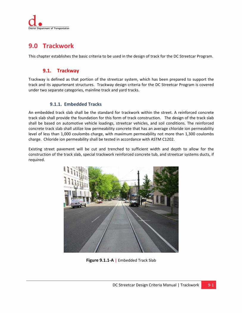
DC Streetcar Design Criteria Manual | Trackwork 9-1
9.0 Trackwork This chapter establishes the basic criteria to be used in the design of track for the DC Streetcar Program.
9.1. Trackway
Trackway is defined as that portion of the streetcar system, which has been prepared to support the track and its appurtenant structures. Trackway design criteria for the DC Streetcar Program is covered under two separate categories, mainline track and yard tracks.
9.1.1. Embedded Tracks
An embedded track slab shall be the standard for trackwork within the street. A reinforced concrete track slab shall provide the foundation for this form of track construction. The design of the track slab shall be based on automotive vehicle loadings, streetcar vehicles, and soil conditions. The reinforced concrete track slab shall utilize low permeability concrete that has an average chloride ion permeability level of less than 1,000 coulombs charge, with maximum permeability not more than 1,300 coulombs charge. Chloride ion permeability shall be tested in accordance with ASTM C1202.
Existing street pavement will be cut and trenched to sufficient width and depth to allow for the construction of the track slab, special trackwork reinforced concrete tub, and streetcar systems ducts, if required.
Figure 9.1.1-A | Embedded Track Slab
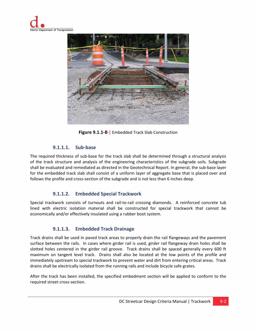
DC Streetcar Design Criteria Manual | Trackwork 9-2
Figure 9.1.1-B | Embedded Track Slab Construction
9.1.1.1. Sub-base
The required thickness of sub-base for the track slab shall be determined through a structural analysis of the track structure and analysis of the engineering characteristics of the subgrade soils. Subgrade shall be evaluated and remediated as directed in the Geotechnical Report. In general, the sub-base layer for the embedded track slab shall consist of a uniform layer of aggregate base that is placed over and follows the profile and cross-section of the subgrade and is not less than 6 inches deep.
9.1.1.2. Embedded Special Trackwork
Special trackwork consists of turnouts and rail-to-rail crossing diamonds. A reinforced concrete tub lined with electric isolation material shall be constructed for special trackwork that cannot be economically and/or effectively insulated using a rubber boot system.
9.1.1.3. Embedded Track Drainage
Track drains shall be used in paved track areas to properly drain the rail flangeways and the pavement surface between the rails. In cases where girder rail is used, girder rail flangeway drain holes shall be slotted holes centered in the girder rail groove. Track drains shall be spaced generally every 600 ft maximum on tangent level track. Drains shall also be located at the low points of the profile and immediately upstream to special trackwork to prevent water and dirt from entering critical areas. Track drains shall be electrically isolated from the running rails and include bicycle safe grates.
After the track has been installed, the specified embedment section will be applied to conform to the required street cross-section.
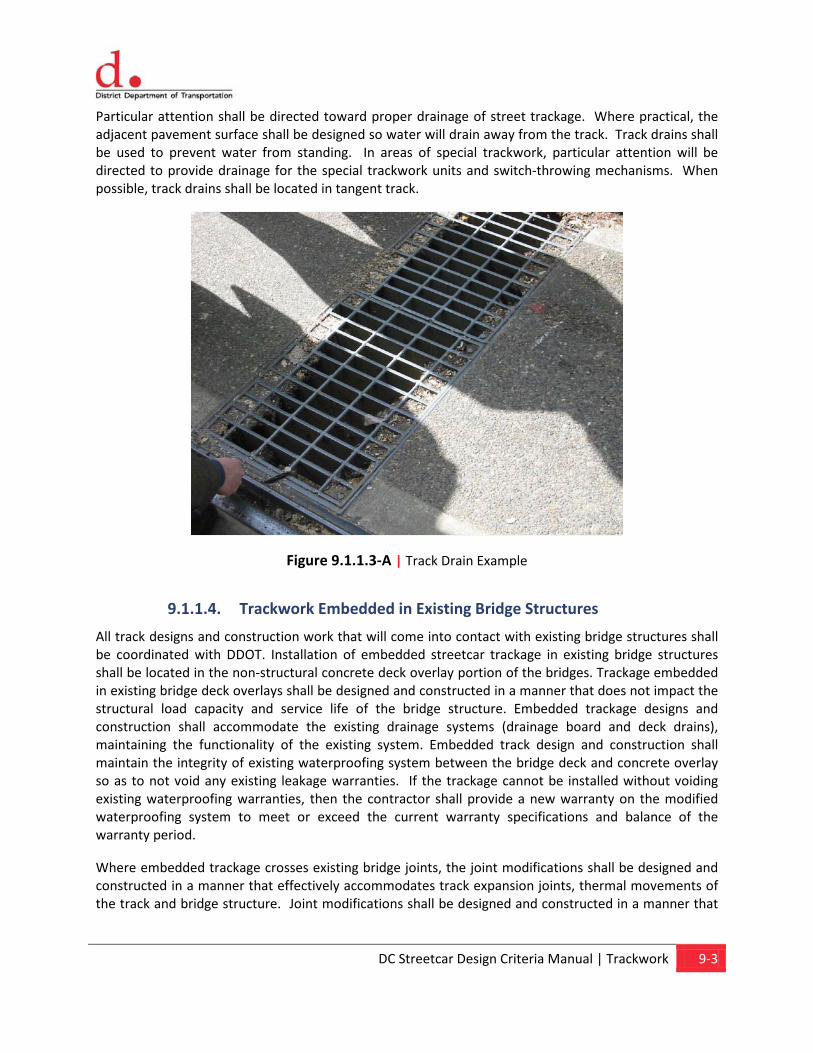
DC Streetcar Design Criteria Manual | Trackwork 9-3
Particular attention shall be directed toward proper drainage of street trackage. Where practical, the adjacent pavement surface shall be designed so water will drain away from the track. Track drains shall be used to prevent water from standing. In areas of special trackwork, particular attention will be directed to provide drainage for the special trackwork units and switch-throwing mechanisms. When possible, track drains shall be located in tangent track.
Figure 9.1.1.3-A | Track Drain Example
9.1.1.4. Trackwork Embedded in Existing Bridge Structures
All track designs and construction work that will come into contact with existing bridge structures shall be coordinated with DDOT. Installation of embedded streetcar trackage in existing bridge structures shall be located in the non-structural concrete deck overlay portion of the bridges. Trackage embedded in existing bridge deck overlays shall be designed and constructed in a manner that does not impact the structural load capacity and service life of the bridge structure. Embedded trackage designs and construction shall accommodate the existing drainage systems (drainage board and deck drains), maintaining the functionality of the existing system. Embedded track design and construction shall maintain the integrity of existing waterproofing system between the bridge deck and concrete overlay so as to not void any existing leakage warranties. If the trackage cannot be installed without voiding existing waterproofing warranties, then the contractor shall provide a new warranty on the modified waterproofing system to meet or exceed the current warranty specifications and balance of the warranty period.
Where embedded trackage crosses existing bridge joints, the joint modifications shall be designed and constructed in a manner that effectively accommodates track expansion joints, thermal movements of the track and bridge structure. Joint modifications shall be designed and constructed in a manner that
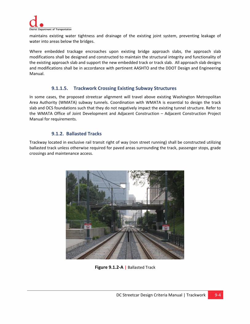
DC Streetcar Design Criteria Manual | Trackwork 9-4
maintains existing water tightness and drainage of the existing joint system, preventing leakage of water into areas below the bridges.
Where embedded trackage encroaches upon existing bridge approach slabs, the approach slab modifications shall be designed and constructed to maintain the structural integrity and functionality of the existing approach slab and support the new embedded track or track slab. All approach slab designs and modifications shall be in accordance with pertinent AASHTO and the DDOT Design and Engineering Manual.
9.1.1.5. Trackwork Crossing Existing Subway Structures
In some cases, the proposed streetcar alignment will travel above existing Washington Metropolitan Area Authority (WMATA) subway tunnels. Coordination with WMATA is essential to design the track slab and OCS foundations such that they do not negatively impact the existing tunnel structure. Refer to the WMATA Office of Joint Development and Adjacent Construction – Adjacent Construction Project Manual for requirements.
9.1.2. Ballasted Tracks
Trackway located in exclusive rail transit right of way (non street running) shall be constructed utilizing ballasted track unless otherwise required for paved areas surrounding the track, passenger stops, grade crossings and maintenance access.
Figure 9.1.2-A | Ballasted Track
DC Streetcar Design Criteria Manual | Trackwork 9-5
9.1.2.1. Sub-ballast
Sub-ballast is defined as a uniformly graded material that will provide a semi-impervious layer between the ballast and the subgrade. It facilitates drainage by shedding water off to the sides of the trackway, shielding the subgrade from moisture that percolates down through the ballast. Sub-ballast material shall be used beneath ballasted track sections.
The required thickness of sub-ballast shall be determined through a structural analysis of the track structure and analysis of the engineering characteristics of the sub-grade soils. In general the sub-ballast layer for the track shall consist of a uniform layer of coarse aggregate that is placed over and follows the profile and cross-section of the sub-grade and is not less than 6 inches deep.
9.1.2.2. Ballast
A No. 5 ballast gradation of granite ballast shall be used for the yard trackway. The ballast gradation number shall be in conformance with the AREMA specifications. A minimum depth of 12 inches of ballast shall be used between the bottom of tie and the top of the sub-ballast (beneath the low running rail). The shoulder ballast shall extend a minimum of 12 in beyond the ends of the ties parallel to the plane formed by the top of the rails. Shoulder ballast shall then slope downward to the sub-ballast at a 2:1 slope. Use of ballast retainer wall or retaining wall will be investigated to prevent ballast from over spilling into pavement areas or in areas with limited right-of way. The final top of ballast elevation shall be 1 inch below the top of the ties, when compacted. Crushed slag or limestone ballast shall not be permitted.
9.1.2.3. Slopes
On ballasted sections, side slopes of earth shall generally be constructed two horizontal to one vertical or flatter. Side slopes of earth steeper than two horizontal to one vertical may be used in special situations to avoid excessive earthwork or right-of-way costs; however, such slopes shall not be used without a soil engineer's determination of slope stability.
9.1.2.4. Ballasted Track Drainage
Ditches, grate drains, and/or underdrains shall be provided at the edges of the track to prevent water from ponding or covering any part of the track structure or contributing to subgrade instability. Minimum ditch grade shall comply with the requirements of Chapter 1, General. In areas where the right-of-way does not allow use of the standard ditch section, underdrains shall be used.
DC Streetcar Design Criteria Manual | Trackwork 9-6
9.2. Trackwork
9.2.1. Embedded and Ballasted Tracks
9.2.1.1. Track Gauge (Embedded and Ballasted Tracks)
Track gauge shall be a standard gauge of 4 ft 8 ½ in (1435mm). The gauge is the distance between the inner sides of the head of rails measured 5/8 in below the top of rails. Wider gauges may be used in some curves, depending on the radius. Track gauge shall be widened up to ½” in for any curve radius of 150 feet or less. Track gauge for curve radius less than 500 feet and greater than or equal to 150 feet shall be incrementally widened from ¼ inch to ½ inch. No gauge widening shall occur in tangent track, or curved track with a radius greater than 500 feet.
Gauge widening shall be at a constant transition rate and not more than 1/4" inch in a distance of 31 feet, to a maximum of ½ inch in 62 feet. Full gauge widening shall be accomplished on the tangent in approach to the point of curve and removed following the point of tangent in simple curves. In spiral curves, gauge widening shall be applied and removed within the spirals. If the spiral is too short for full gauge widening to be accomplished beyond the rate exceeding ¼ inch in 31 feet, sufficient gauge widening shall be placed in the approach tangents to meet the rate of ¼ inch in 31 feet. If adjacent curves with both requiring widening are too close together to allow run out of the gauge widening, the widened gauge shall be maintained between the curves. The track gauge in paved track using AREMA 115RE tee rail shall be established by using TCRP Report 57, “Track Design Handbook for Light Rail Transit” Gage Determination Analysis, and the track gauge in paved track using girder rail shall be established by using TCRP Report 57, “Track Design Handbook for Light Rail Transit” Gage Determination Analysis. Gauge widening on curves is not required for girder or block rail.
9.2.1.2. Premium Rail (Embedded and Ballasted Track)
Premium high-strength rail shall be shall be fully heat treated or head hardened rail and is suitable for installation in ballasted and embedded track. Premium high-strength rail shall be used at station areas, other areas of frequent starting and stopping, such as traffic signal locations, on grades of five percent of greater, on curves with radius equal to or less than 500 feet, and in areas where high wear rates or internal rail stresses are anticipated. Premium rail shall also be used throughout all special trackwork.
9.2.1.3. Running Rail (Embedded and Ballasted Tracks)
There are three types of rail sections that can be used and are listed below:
• AREMA 115RE tee rail
• 51R1 girder rail (formally Ri52) – Low profile rail (130mm) with wider groove
• 53R1 girder rail (formally Ri53) – Low profile rail (130 mm)
• LK1 grooved block rail
DC Streetcar Design Criteria Manual | Trackwork 9-7
Selection of the running rail section must be performed with the consideration for economy, strength, and availability. AREMA 115RE tee rail is manufactured within the United States on a large scale and can be purchased “off-the-shelf”. Currently, girder rail is not manufactured within the United States. The Federal Transit Administration (FTA) Buy America requirement (49 CFR Part 661) may not permit the purchase of girder rail, or any other materials not manufactured within the United States for projects receiving federal grants. LK1 grooved block rail is currently manufactured within the United States at a small scale for testing proposes.
The AREMA 115RE tee rail requires a formed flangeway within the concrete track slab to accommodate the streetcar wheel flange. Restraining rail (guarded track) is used on sharp curves to reduce wear by restraining the wheels away from the outer rail. Girder rail and LK1 grooved block rail do not require a formed flangeway since they both contain a “lip” which the concrete track slab would abut to. Both AREMA 115RE tee rail and girder rail have been used extensively within the United States for in-street track, however LK1 grooved block rail has only been used in Europe. All new rail shall conform to the current AREMA “Specification for Steel Rails”.
Horizontal bending of rail should be performed in roller straighteners for curve radii below 120m (400 ft). All running rails shall be procured in the longest lengths practical for transportation logistics and then electric flash butt welded into the longest continuous length feasible for installation. Field welds that conform to AREMA Specifications shall then be used to join the lengths of flash butt welded rail.
On existing bridge structures a custom or modified rail will be required to permit installation of the rails into the 6 inch thick topping slab. The rail shall be designed to meet the above strength, durability and installation criteria.
Where high strength/premium rail is used in curves, it shall extend into tangent track on the approach and departure ends of the curve a minimum distance of 10 feet.
Rails shall extend beyond the end of track slab approximately 3 feet within the pavement to accommodate future extension.
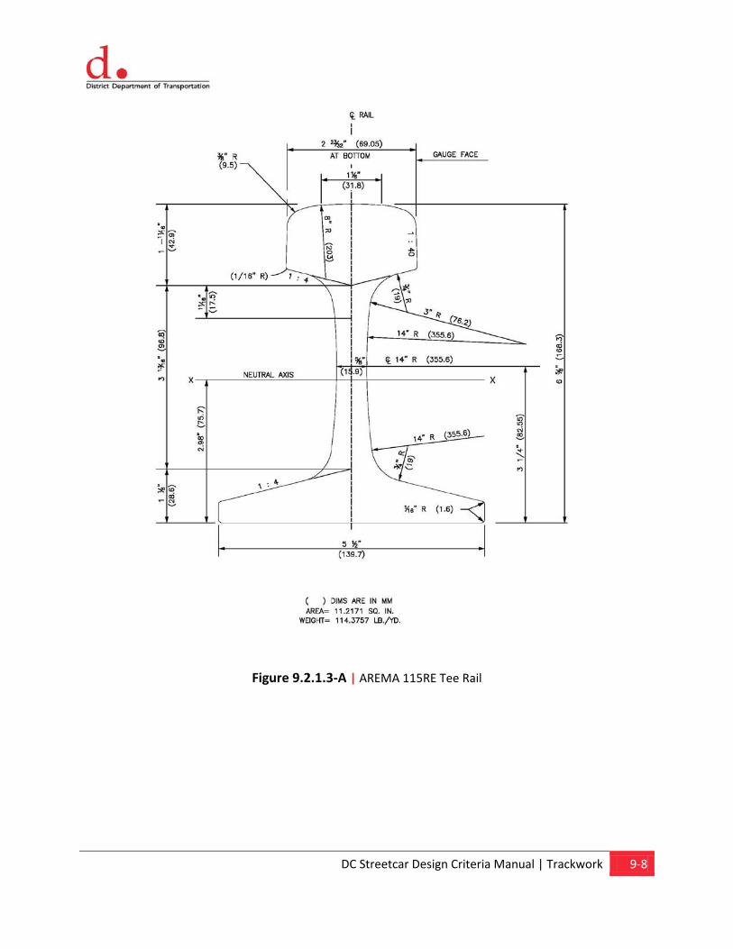
DC Streetcar Design Criteria Manual | Trackwork 9-8
Figure 9.2.1.3-A | AREMA 115RE Tee Rail
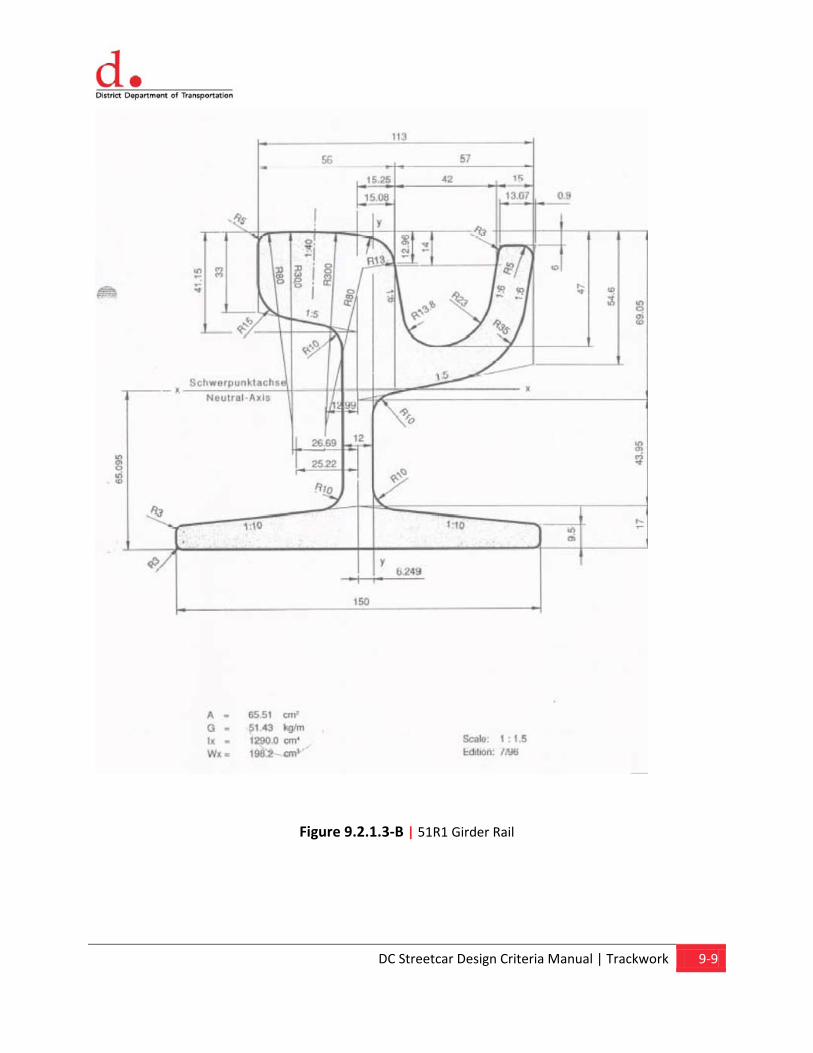
DC Streetcar Design Criteria Manual | Trackwork 9-9
Figure 9.2.1.3-B | 51R1 Girder Rail
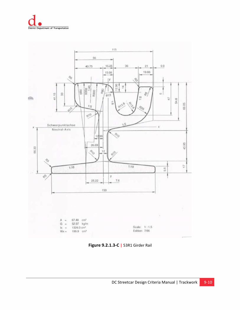
DC Streetcar Design Criteria Manual | Trackwork 9-10
Figure 9.2.1.3-C | 53R1 Girder Rail
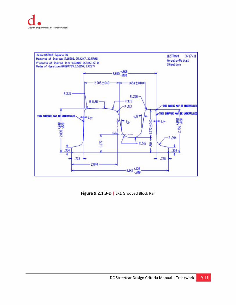
DC Streetcar Design Criteria Manual | Trackwork 9-11
Figure 9.2.1.3-D | LK1 Grooved Block Rail
DC Streetcar Design Criteria Manual | Trackwork 9-12
9.2.1.4. Rail Fastenings and Rail Seats
Running rail shall be fastened to its support for each type of track construction. All rail fastenings and rail seats shall be in accordance with the current and applicable AREMA specifications.
9.3. Electrical Insulation
All tracks regardless of the construction shall be electrically isolated. Tracks within the maintenance facility must be grounded for safety of maintenance crews.
9.3.1. Embedded Track
Embedded track rail shall be encased in an elastomeric material that meets the criteria specified in Chapter 14, Stray Current Corrosion Control and secured in place by the use of tie bars/rail clips assembly and/or anchor plates/rail clips assembly. The preferred Elastomeric material shall be the pre-formed rubber boot, but could be a poured in place grout if the track is embedded in concrete. The embedment material shall be set ¼ in below the top of rail on the field side to prevent the wheel tread from damaging the pavement material.
Electrical testing of the embedded track will be required to demonstrate compliance with the corrosion control measures outlined in Chapter 14, Stray Current Corrosion Control. The minimum resistance of the track to ground will be a minimum of 200 ohms per 1000 ft.
During final design, alternative embedment methods for paved track shall be evaluated. If an alternate design for paved track proves to be advantageous, it may be substituted for the existing design with the approval of DDOT.
9.3.2. Ballasted Track (Yard Tracks)
Ballasted tracks shall be constructed with concrete or wood ties. The fastening system for the ties shall provide for electrical isolation unless included in pavement where the boot shall be used.
Electrical testing of the embedded track will be required to demonstrate compliance with the corrosion control measures outlined in Chapter 14, Stray Current Corrosion Control.
9.4. Special Trackwork
Special trackwork shall be located on constant profile grades and in tangent sections of track only. There shall be no superelevation in any special trackwork units.
DC Streetcar Design Criteria Manual | Trackwork 9-13
9.4.1. Embedded Track
Turnouts, crossovers and crossing diamonds in the embedded streetcar track or embedded track special trackwork units shall be constructed in a concrete tub track slab with rubberized spray-on liner to electrically isolate the special trackwork from ground. Special trackwork designs should conform to European design standards. These turnouts are manufactured within the United States. Turnouts shall have minimum 20m (65.62 feet) radius double-flexive tongue switches and flange-bearing mono-block curved frogs. Coordination with the vehicle manufacturer is required to ensure the vehicle can negotiate a 20m (65.62 feet) turnout.
• Efforts shall be made for embedded track turnouts to be located so that switch machines are not located in a pedestrian crosswalk and areas of shared use with vehicular traffic so as to enhance the safety of maintenance technicians.
• Embedded special trackwork shall be positioned so that switches, frogs and crossing diamonds are not located in designated pedestrian and bicycle paths so as to enhance the safety of both pedestrians and small-wheeled vehicles (e.g., wheelchairs) crossing the tracks.
Turnout and crossing diamond frogs shall be designed to accommodate the narrow tread streetcar wheel and hence shall be configured for flange bearing use. On curved streetcar crossing diamonds, consideration shall be given to making the outer rail of the crossing diamond fully flange-bearing and the portions along the inner rail tread-bearing so as to take advantage of the steering effects of the different rolling radii of the flange tip versus the tread.
Special drainage provisions shall be made in paved track turnouts to preclude standing water in flangeways, tongue areas, and in switch-throwing mechanisms.
Electrical testing of the embedded track will be required to demonstrate compliance with the corrosion control measures outlined in Chapter 14, Stray Current Corrosion Control.
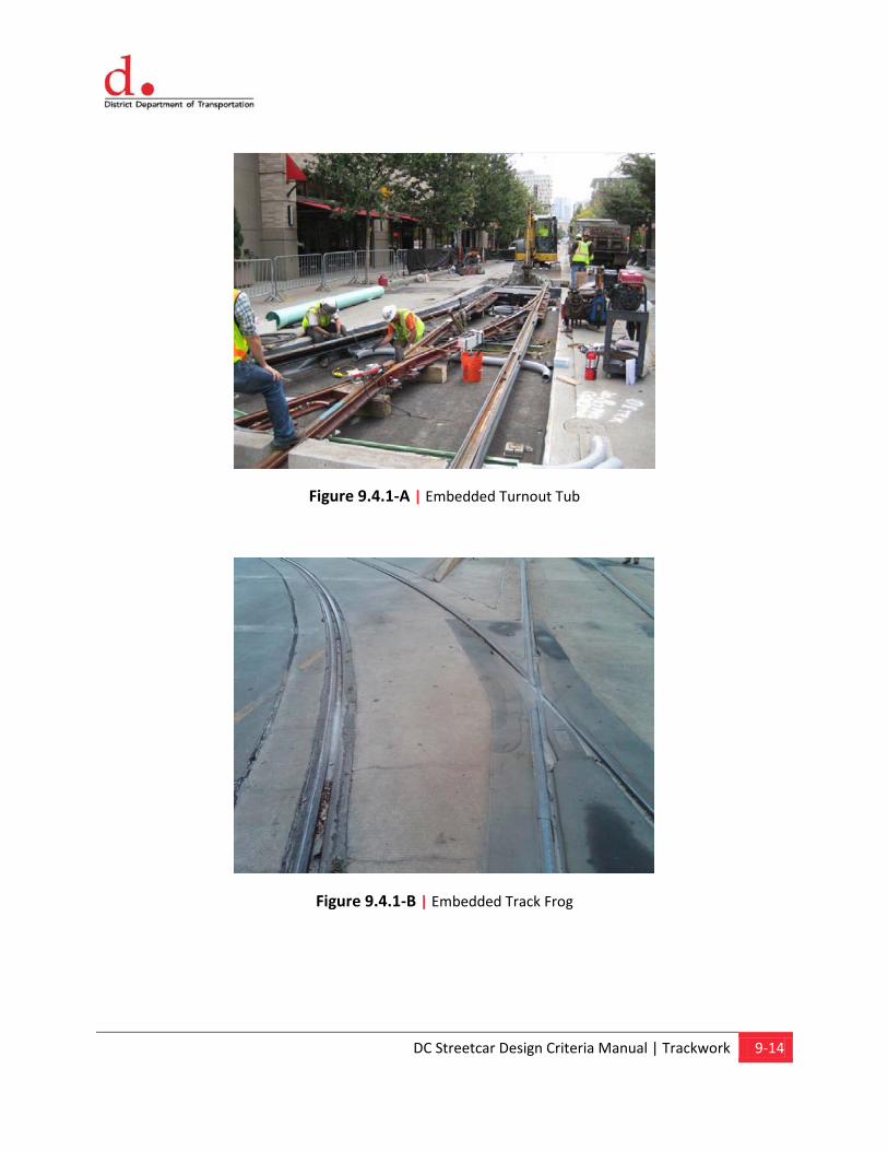
DC Streetcar Design Criteria Manual | Trackwork 9-14
Figure 9.4.1-A | Embedded Turnout Tub
Figure 9.4.1-B | Embedded Track Frog
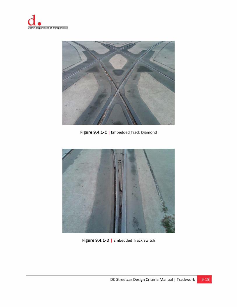
DC Streetcar Design Criteria Manual | Trackwork 9-15
Figure 9.4.1-C | Embedded Track Diamond
Figure 9.4.1-D | Embedded Track Switch
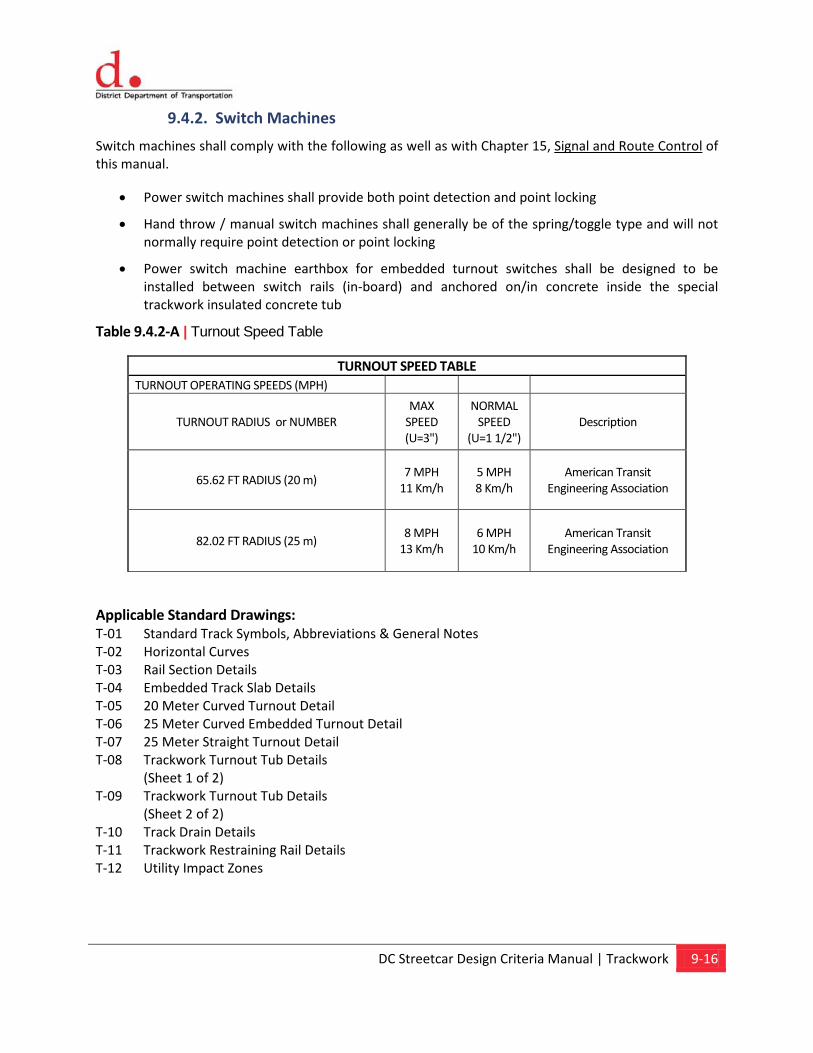
DC Streetcar Design Criteria Manual | Trackwork 9-16
9.4.2. Switch Machines
Switch machines shall comply with the following as well as with Chapter 15, Signal and Route Control of this manual.
• Power switch machines shall provide both point detection and point locking
• Hand throw / manual switch machines shall generally be of the spring/toggle type and will not normally require point detection or point locking
• Power switch machine earthbox for embedded turnout switches shall be designed to be installed between switch rails (in-board) and anchored on/in concrete inside the special trackwork insulated concrete tub
Table 9.4.2-A | Turnout Speed Table
TURNOUT SPEED TABLE TURNOUT OPERATING SPEEDS (MPH)
TURNOUT RADIUS or NUMBER MAX
SPEED (U=3")
NORMAL SPEED
(U=1 1/2") Description
65.62 FT RADIUS (20 m) 7 MPH
11 Km/h 5 MPH 8 Km/h
American Transit Engineering Association
82.02 FT RADIUS (25 m) 8 MPH
13 Km/h 6 MPH
10 Km/h American Transit
Engineering Association
Applicable Standard Drawings: T-01 Standard Track Symbols, Abbreviations & General Notes T-02 Horizontal Curves T-03 Rail Section Details T-04 Embedded Track Slab Details T-05 20 Meter Curved Turnout Detail T-06 25 Meter Curved Embedded Turnout Detail T-07 25 Meter Straight Turnout Detail T-08 Trackwork Turnout Tub Details
(Sheet 1 of 2) T-09 Trackwork Turnout Tub Details
(Sheet 2 of 2) T-10 Track Drain Details T-11 Trackwork Restraining Rail Details T-12 Utility Impact Zones
Chapter 10 Structural
Content
10.1. General 10.2. Applicable Codes and Standards 10.3. Loads and Forces 10.4. Soils 10.5. Reinforced and Prestressed Concrete 10.6. Structural Steel 10.7. Foundations 10.8. Support of Excavation Structures 10.9. Streetcar Tracks on Bridges
DC Streetcar Design Criteria Manual | Structural 10-1
10.0 Structural
10.1 General
This chapter defines the structural design criteria and standards for the DC Streetcar Program. Structures anticipated include catenary bridges, underground structures, and other miscellaneous structures.
10.2 Applicable Codes and Standards
The following are some of the codes, manuals and specifications that shall be applicable to the design of structures (all publications listed shall be the latest edition unless noted otherwise):
• American Association of State Highway and Transportation Officials (AASHTO) LRFD Bridge Design Specifications hereinafter referred to the AASHTO LRFD Specifications
• DDOT Design and Engineering Manual
• AREMA Manual for Railway Engineering hereinafter referred to as the AREMA Manual
• American Concrete Institute (ACI) ACI 318 Building Code Requirements for Reinforced Concrete hereinafter referred to as ACI 318
• American Institute of Steel Construction (AISC) Specification for Structural Steel Buildings hereinafter referred to as the AISC Specifications
• Concrete Reinforcing Steel Institute (CRSI) Manual of Standard Practice hereinafter referred to as the CRSI Manual
• Adjacent Construction Project Manual
• District of Columbia Building Codes and all references and standards cited therein
• NFPA 101 and 130
• District of Columbia Accessibility Code (and the Americans with Disabilities Act)
• AASHTO: American Association of State Highway and Transportation Officials
• District of Columbia Department of Transportation (DDOT) requirements
• International Code Council (ICC)
• Relevant ASHRAE, ASPE, ANSI, NFPA, ASTM, and AWW Standards
• National Electrical Safety Code (NESC)
• National Electric Code (NEC)
Agencies or entities who publish/author codes, standards and other requirements that may be applicable to the project are listed below. The following is a partial list and it is the Designer’s legal,
DC Streetcar Design Criteria Manual | Structural 10-2
contractual and professional duty to design in accordance with all the applicable requirements, whether or not referenced herein.
• American Association of State Highway and Transportation Officials (AASHTO)
• Americans With Disabilities Act (ADA)
• American Concrete Institute (ACI)
• American Society for Testing Materials (ASTM)
• American Institute of Steel Construction (AISC)
• American National Standards Institute (ANSI)
• American Society of Civil Engineers (ASCE)
• American Society of Mechanical Engineers (ASME)
• American Welding Society (AWS)
• Concrete Reinforcing Steel Institute (CRSI)
• Concrete Specifications Institute (CSI)
• District of Columbia Accessibility Code
• District of Columbia Building Codes
• District Department of Transportation (DDOT)
• District of Columbia Water and Sewer Authority (DCWATER)
• District Department of the Environment (DDOE)
• International Codes (I-Codes)
• National Fire Protection Association (NFPA)
• National Electric Code (NEC)
• National Electrical Manufactures Association (NEMA)
• Occupational Safety & Health Administration (OSHA)
• Pre-stressed Concrete Institute (PCI)
• Underwriters Laboratory (UL)
• Washington Metropolitan Area Transit Authority (WMATA)
For additional codes, standards, manuals and requirements, please refer to Chapter 1, General.
DC Streetcar Design Criteria Manual | Structural 10-3
10.3 Loads and Forces
10.3.1 Dead Loads
The dead load shall consist of the estimated weight of the basic structure and the weight of all non-structural elements permanently supported by the structure such as: trackwork, electrification, railings, barriers, utilities, walkways, canopies, walls, and partitions.
10.3.2 Live Loads
Structures subject to streetcar loading shall be designed for the vehicle loading for the particular DC Streetcar.
Structures subject to railroad freight train loading shall be designed for Cooper E-80 railroad loading.
Structures subject to highway loading shall be designed for HL-93 truck loads.
10.3.3 Other Loads and Forces
Other loads and forces (i.e., wind, thermal, longitudinal, centrifugal, shrinkage, etc.) on structures shall in accordance with Chapter 1, General, and the following requirements:
• Structures subject to streetcar or highway loading: AASHTO LRFD Specifications
• Structures subject to railroad loading: AREMA Manual
• Other structures: District of Columbia Building Codes
• Structures constructed in the sidewalk shall be designed in accordance with the DDOT Design and Engineering Manual
10.4 Soils
The soils in the DC area vary widely. Soil and geologic data for the preliminary design of structures shall be site specific data.
10.5 Reinforced and Prestressed Concrete
Reinforced and prestressed concrete structures shall be designed in accordance with Chapter 1, General, and the following requirements:
• Structures subject to streetcar loading: AASHTO LRFD Specifications, ACI 318 and CRSI Manual
• Structures subject to railroad loading: AREMA and CRSI Manual
• Structures subject to highway loading: AASHTO LRFD Specifications, DDOT and CRSI Manual
• Buildings and other structures: District of Columbia Building Code, ACI 318 and CRSI Manual

DC Streetcar Design Criteria Manual | Structural 10-4
10.6 Structural Steel
Structural Steel structures shall be designed in accordance with Chapter 1, General, and the following requirements:
• Structures subject to streetcar loading: AASHTO and AISC
• Structures subject to railroad loading: AREMA Manual
• Structures subject to highway loading: AASHTO and DDOT Standards
• Buildings and other structures: District of Columbia Building Code and AISC Specifications
10.7 Foundations
Foundations for structures shall be designed in accordance with the site specific soil and geological data, Chapter 1, General, and the following requirements:
• Structures subject to streetcar loading: AASHTO LRFD Specifications
• Structures subject to railroad loading: AREMA Manual
• Structures subject to highway loading: AASHTO LRFD Specifications and DDOT Standards
10.8 Support of Excavation Structures
When planning for structures requiring excavation support, spatial and physical constraints (adjacent structures, utilities, etc.) shall be considered. Support of excavation structures shall generally be designed by the contractor in accordance with Chapter 1, General.
10.9 Streetcar Tracks on Bridges
Tracks on bridges may be embedded (shared with other vehicles), direct fixation, or ballasted. Where thermal forces in the rail cannot be restrained and rail expansion and contraction must be accommodated, rail expansion joints shall be provided. Refer to TCRP 57 – Track Handbook for Light Rail Design, Chapter 7 – Aerial Structures/Bridges.
Chapter 11 Vehicle
Content
11.1 Vehicle Type 11.2 Handicapped Accessibility 11.3 Operating Environment 11.4 Traction Power Supply Voltages 11.5 Vehicle Weight and Passenger
Loadings 11.6 Vehicle Dimensions 11.7 Vehicle Performance 11.8 Vehicle Noise 11.9 Vehicle Vibration 11.10 Electromagnetic Interference &
Compatibility
DC Streetcar Design Criteria Manual | Vehicle 11-1
11.0 Vehicle
11.1. Vehicle Type
• Articulated
• Minimum two passenger entry doors per side
• Low floor entry in center section
• Double-ended (cab at each end)
• Single unit operation
• Capability of towing one other vehicle (See Section 11.7.9)
• Future procurements will have capability of operating without an overhead wire
11.1.1. Alternative Propulsion
The use of alternative propulsion for vehicles will be required at some locations within the District of Columbia. DDOT is at the beginning stages of exploring the use of alternative propulsion for vehicles on specific projects. The design criteria will be updated to provide design guidelines for the use of alternative propulsion vehicles.
11.2. Handicapped Accessibility
• Level boarding from 14 ± 1/8 inch station platforms
• Future alignments may require at least one platform bridging device per side for wheelchair access from 10 ± 1/4 inch station platforms
• Space for two wheelchairs in each car
11.3. Operating Environment
11.3.1. ROW Description
• Vehicles shall operate on city streets with a speed of no more than 30 mph (50 km/h)
• Station stops will be on curb extensions sized to accommodate all doors of the streetcar, but may not extend the entire length of the vehicle
11.3.2. Guideway Design Criteria
• Rail types: AREMA 115RE Tee-Rail or Girder Rail
• Minimum horizontal curve radius: 65.62 feet (20 m)
• Minimum vertical curve, crest: 820.21 feet (250 m)
DC Streetcar Design Criteria Manual | Vehicle 11-2
• Minimum vertical curve, sag: 820.21 feet (250 m)
• Minimum turnout size: 65.62 feet (20 m)
• Track gauge: 56.5 inches (1.435 m)
• Average track cross slope: 0.5 inches (12.5 mm)
• Maximum track cross slope: 3 inches (76.2 mm)
• Maximum gradient: 9 %
• Reverse vertical curves: Either a crest and sag of 820 ft (250 m) separated by a tangent section of 24.6 feet (7.5 m) or a crest and sag of 1,148.3 feet (350 m) separated by no tangent track
• Compound curves: A 65.6 feet (20 m) curve superimposed on a 1,476.4 feet (450 m) vertical crest or sag
11.3.3. Clearance Envelopes
• The vehicle shall meet the clearance requirements of Chapter 3, Track Alignment and Vehicle Clearance
11.3.4. Climate Conditions
• See Chapter 1, General.
11.4. Traction Power Supply Voltages
The following ratings are the criteria upon which the design of the traction power distribution system will be based:
No Load Catenary Voltage 795 Vdc
Maximum Catenary Voltage 925 Vdc
Vehicle Operating Voltage (Minimum) 525 Vdc
11.5. Vehicle Weight and Passenger Loadings
Weight Definitions:
• AW0: Maximum 1,000 lb/ft (1,500 kg/m) of length
• AW1: AW0 + full seated passenger load + operator weight
• AW2: AW1 + standees at 4 persons per m2
• AW3: AW2 + standees at 6 persons per m2
• AW4: AW3 + standees at 6.6 persons per m2
11.5.1. Weight Imbalance Limits
• Wheel loadings within the same truck shall not vary by more than 10%
DC Streetcar Design Criteria Manual | Vehicle 11-3
• Axle loadings between trucks of the same type shall not vary more than 10%
11.6. Vehicle Dimensions
11.6.1. Carbody Dimensions
• Maximum vehicle length: 62.3 to 72.2 feet (19.0 m to 22 m)
• Vehicle width: 7.9 to 8.4 feet (2.4 m to 2.5 m)
• Floor height above T/R at AW0, low floor section: 14 inches (350 mm)
• Minimum interior ceiling height, finished floor to finished ceiling, along vehicle centerline: 6.56 feet (2.0 m)
• Minimum side door opening width: 4 feet (1,220 mm)
• Minimum side door opening height: 78 inches (1,980 mm)
• Maximum roof-mounted equipment height, excluding the pantograph, above T/R, with new wheels, and AW0 passenger weight: 11.6 feet (3,540 mm)
• Minimum depth of interior step treads (if used) 11 inches (280 mm)
• Minimum height of interior step treads (if used) 11 inches (280 mm)
11.6.2. Pantograph Dimensions
• Maximum height above T/R in the lockdown position, with new wheels, vehicle at AW0 passenger weight: 12.5 feet (3.80 m)
• Pantograph operating height under dynamic conditions, vehicle weight from AW0 to AW3, Minimum: 13.0 feet (3.95 m) and with new to fully worn wheels: Maximum: 20.5 feet (6.25 m)
• Maximum collector width over horns: (5.58 feet) 1.70 m
• Minimum carbon shoe length: (41.3 inches) 1,050 mm
• Maximum longitudinal distance from vehicle pivot point to centerline of pantograph shoe, locked down 4.18 feet (1275 mm)
11.6.3. Wheel Dimensions
• Nominal diameter, new 19.7 to 24 inches (500 to 610 mm)
• Minimum allowable wheel diameter wear (2 inches) 50 mm
• Profile: A preferred wheel profile is shown in Fig. 9-1. The final wheel profile shall be recommended by the vehicle manufacturer and approved by DDOT
DC Streetcar Design Criteria Manual | Vehicle 11-4
• Back-to-Back dimension: (53.82 inches) 1,367 mm
11.6.4. Truck Dimensions
• Centerline-to-centerline truck spacing: Sufficient to comply with dynamic envelope
• Truck wheelbase: 67 to 75 inches (1.70 to 1.90 m)
11.7. Vehicle Performance
11.7.1. Propulsion and Braking General Criteria
• All acceleration, braking and jerk rates are based on level, tangent, dry track in still air unless otherwise noted.
• Propulsion equipment shall be designed for nominal performance at 750 Vdc, over a range of 525 Vdc to 925 Vdc, except that:
1) The initial rate need only be available in the speed range of 0 to 20 mph (0 to 32 km/h) and at voltages of 700 Vdc and above. Below 700 Vdc, the speed to which the initial acceleration rate is held may decrease proportional to the OCS voltage.
2) Braking rates shall be independent of the OCS voltage and once initiated, shall not require the presence of OCS voltage.
3) All specified performance shall be provided over the full range of:
• Wheel wear
• Climatic conditions
11.7.2. Acceleration Requirements
• Maximum acceleration, at all vehicle weights from AW0 to AW2. Rate may decrease linearly from AW2 to AW4: 3.0 mph/s (1.34 m/s2) + 5%
• Time to reach 25 mph (40 km/h) from a standing start at AW2 loading: 10 seconds
11.7.3. Continuous and Balancing Speed Requirements
• The vehicle shall be capable of operating at any speed from 0 to 30 mph (50 km/h) continuously, at AW2 loading, on any portion of the alignment, without overheating or damage to the vehicle.
• The vehicle shall have a minimum balancing speed of 30 mph (50 km/h) on level tangent track, over the specified range of wheel wear, at nominal line voltage (750 Vdc), and at AW2 loading in still air
• Maximum safe speed with fully worn wheels shall be at least 42 mph (68 km/h)
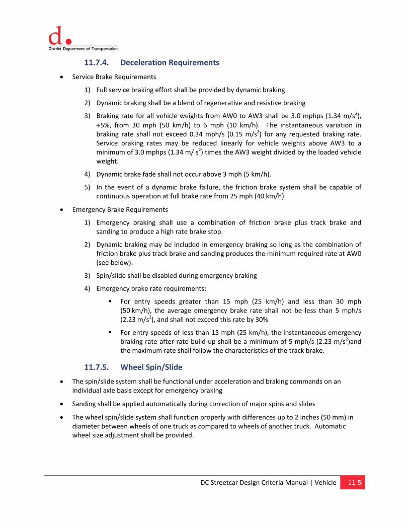
DC Streetcar Design Criteria Manual | Vehicle 11-5
11.7.4. Deceleration Requirements
• Service Brake Requirements
1) Full service braking effort shall be provided by dynamic braking
2) Dynamic braking shall be a blend of regenerative and resistive braking
3) Braking rate for all vehicle weights from AW0 to AW3 shall be 3.0 mphps (1.34 m/s2), +5%, from 30 mph (50 km/h) to 6 mph (10 km/h). The instantaneous variation in braking rate shall not exceed 0.34 mph/s (0.15 m/s2) for any requested braking rate. Service braking rates may be reduced linearly for vehicle weights above AW3 to a minimum of 3.0 mphps (1.34 m/ s2) times the AW3 weight divided by the loaded vehicle weight.
4) Dynamic brake fade shall not occur above 3 mph (5 km/h).
5) In the event of a dynamic brake failure, the friction brake system shall be capable of continuous operation at full brake rate from 25 mph (40 km/h).
• Emergency Brake Requirements
1) Emergency braking shall use a combination of friction brake plus track brake and sanding to produce a high rate brake stop.
2) Dynamic braking may be included in emergency braking so long as the combination of friction brake plus track brake and sanding produces the minimum required rate at AW0 (see below).
3) Spin/slide shall be disabled during emergency braking
4) Emergency brake rate requirements:
For entry speeds greater than 15 mph (25 km/h) and less than 30 mph (50 km/h), the average emergency brake rate shall not be less than 5 mph/s (2.23 m/s2), and shall not exceed this rate by 30%
For entry speeds of less than 15 mph (25 km/h), the instantaneous emergency braking rate after rate build-up shall be a minimum of 5 mph/s (2.23 m/s2)and the maximum rate shall follow the characteristics of the track brake.
11.7.5. Wheel Spin/Slide
• The spin/slide system shall be functional under acceleration and braking commands on an individual axle basis except for emergency braking
• Sanding shall be applied automatically during correction of major spins and slides
• The wheel spin/slide system shall function properly with differences up to 2 inches (50 mm) in diameter between wheels of one truck as compared to wheels of another truck. Automatic wheel size adjustment shall be provided.

DC Streetcar Design Criteria Manual | Vehicle 11-6
11.7.6. Jerk limits
• In response to a step input command signal, the average rate of change of actual acceleration or deceleration, after any mode change dead time, for maximum power or maximum service brake, shall be between 2.5 mph/s/s (1.1 m/s3) and 4.5 mph/s/s (2.0 m/s3).
• For lower power and brake applications, average jerk rate shall be between 1.0 mph/s/s (0.45 m/s3) and 4.5 mph/s/s (2.0 m/s3).
• Release of power when traversing overhead primary power isolation gaps need not be jerk limited; however, the reapplication of power must be jerk limited. OCS power isolation gaps do not exceed 12 inches (300 mm).
• Emergency brake applications shall not be jerk limited.
11.7.7. Mode Change Dead Times
• Mode change dead time shall be less than 400 ms for the following direct mode changes, with one exception as noted:
1) Power to brake
2) Power to coast
3) Coast to brake
4) Coast to power
5) Brake to power below 6 mph (10 km/h). For the direct mode change brake to power above 5 km/h (3.2 mph), the mode change dead time shall be 600 ms.
• Mode change dead times for emergency brake applications shall be 400 ms or less, regardless of the original mode.
• Mode change dead time shall be measured from the time that the control trainline(s) changes state until the new commanded acceleration or deceleration reaches 90% of its former commanded value for mode changes to coast, or 10% of the new commanded value for mode changes from coast, or 10% of the new commanded value for mode changes between brake and power.
11.7.8. Parking Brake
• The parking brake shall be capable of holding a vehicle at all weights up to AW4 on a grade of 9%
11.7.9. Duty Cycle
• The vehicle shall be capable of operating continuously at AW2 passenger loading on a duty cycle comprised of full power acceleration, 30 mph (50 km/h) speed limit cruise, full service deceleration and 10 second dwell times over the specified alignment.
• An operating vehicle shall be capable of towing an inoperative vehicle with the brakes released (not functional). Full acceleration and braking tractive effort shall be available on the operative

DC Streetcar Design Criteria Manual | Vehicle 11-7
vehicle. Operative vehicles at AW0 weight shall have the capability to tow an inoperative vehicle at AW3 weight to the next available station (at any location on the alignment), unload all passengers, then move the empty, inoperative vehicle to the shop via the worst case routing.
• If dynamic braking on a vehicle or truck becomes inoperative the vehicle may have a speed restriction imposed of no less than 20 mph. A vehicle in this state shall have the capacity to perform a full round trip at restricted speed and AW2 load weight.
11.8. Vehicle Noise
11.8.1. General Criteria
• All sound measurements shall be performed using methods and equipment meeting IEC 179 and ISO 2204
• Unless otherwise noted, noise limits given below apply only to continuously operating equipment
11.8.2. Interior Noise Limits
• Measurements of interior noise shall be taken in accordance with ISO 3381
• The noise level measured per ISO 3381 shall not exceed 68dBA with the vehicle stationary, all doors and windows closed, and all auxiliary equipment operating simultaneously under normal conditions.
• Interior noise shall not exceed 75 dBA as measured per ISO 3381 operating on smooth rail at any speed up to 30 mph (50 km/h) and under any acceleration or deceleration condition.
11.9. Vehicle Vibration
11.9.1. Vibration Limits
Equipment and auxiliaries mounted anywhere on the carbody or trucks shall not cause vertical or horizontal vibrations anywhere on the vehicle floor, walls, ceiling panels and seat frames, at any speed from 0 to 30 mph (50 km/h), and under any acceleration or braking condition (except emergency braking) in excess of the following:
• Below 1.4 Hz: Max. peak-to-peak deflection of 0.098 inches (2.5 mm)
• 1.4 Hz. to 20 Hz.: Peak acceleration of 0.328 feet/s2 (0.1 m/s2 )
• Above 20 Hz: Peak velocity of 0.00246 feet/s (0.75 mm/s)
11.10. Electromagnetic Interference & Compatibility
11.10.1. General Criteria
Electromagnetic compatibility shall be insured by the use of EN5021-3-1 for railway applications.
DC Streetcar Design Criteria Manual | Vehicle 11-8
11.10.2. Radiated Emission Limits
Radiated emission limits shall be in accordance with EN5021-3-1.
11.10.3. Conducted Emission Limits
Measurement procedures and terminology for conductive emissions shall be per UMTA-MA-06-0153-85-11. Frequency-specific limits are as follows:
• From 0 to 40 Hz: 10 Amperes maximum
• From 40 Hz to 120 Hz: 2 Amperes maximum
• From 120 Hz to 320 Hz: 10 Amperes maximum
11.10.4. Inductive Emission Limits
Measurement procedures and terminology for inductive emissions shall be per UMTA-MA-06-0153-85-8. Frequency-specific limits are as follows:
• 20 Hz to 20 kHz: 20 mV, RMS, rail-to-rail
This condition shall be met by each piece of individual power equipment, as well as, the simultaneous operation of all the equipment.
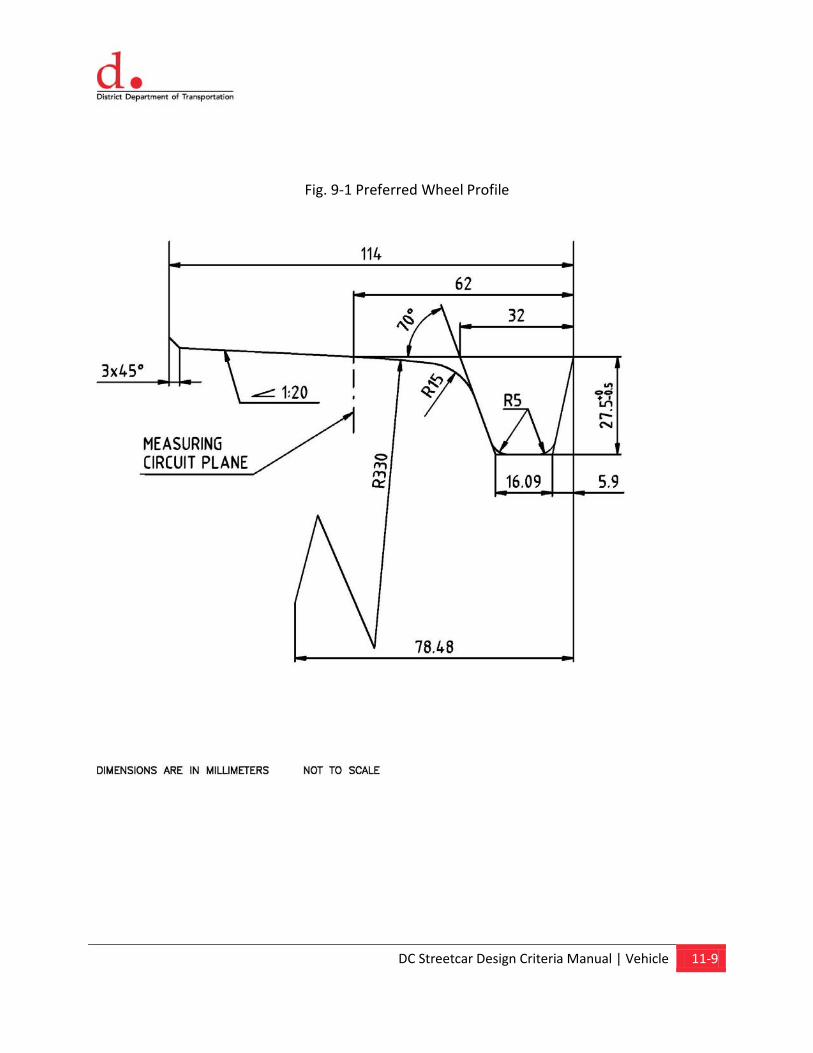
DC Streetcar Design Criteria Manual | Vehicle 11-9
Fig. 9-1 Preferred Wheel Profile
Chapter 12 General
Content
12.1. General 12.2. Applicable Codes and Standards 12.3. Materials of Construction 12.4. Structural 12.5. Facility Vehicle Interface 12.6. Corrosion Control and Safety
Grounding 12.7. Acoustics 12.8. Maintenance 12.9. Mechanical Systems 12.10. Access for the Mobility Impaired 12.11. Functional Requirements 12.12. Site Selection 12.13. Storage Yard
12.14. Interior Cleaning Area 12.15. Automobile Parking and On-Site
Roads 12.16. Outside Storage Areas 12.17. Fire Protection System 12.18. Yard Lighting 12.19. Security 12.20. Refuse/Recycling Collection 12.21. Landscaping 12.22. Streetcar Shop Layout 12.23. Shop Functional Areas 12.24. Support Areas for Shops 12.25. Central Maintenance, Operations and
Administrative Areas 12.26. Exterior Streetcar Wash Facility 12.27. Electrical Services
DC Streetcar Design Criteria Manual | Maintenance and Operations Facility 12-1
12.0 Maintenance and Operations Facility
12.1 General
The DC Streetcar Maintenance and Operations Facility (MOF) will perform daily and routine inspections, maintenance, on-car repairs, and interior/exterior cleaning of the streetcars. The facility will also serve as a storage and component change-out location.
The facility is intended as a light maintenance facility with minor component rebuild, truck overhaul and body repairs, vehicle parts painting, and off-vehicle wheel truing. Machine shop work and sheet metal work would be performed at another location. This may be accomplished by contracting out to local shops with space and equipment to perform the work.
Dependent upon the location of the MOF and where practical, efforts shall be taken to make the building mixed-use, or to allow for future vertical expansion to include other uses (parking, office, residential).
12.2 Applicable Codes and Standards
Design requirements for the building, shop areas and yard shall comply with all federal, state, and local laws, regulations, rules, requirements, and the preservation of natural resources as well as all laws, ordinances, rules, regulations and lawful orders of any public entity bearing on the performance of the work. See Chapter 1, General, for additional information.
All new DDOT facilities over 10,000 square feet in area shall conform the “District Department of General Services” (DGS) requirements. Refer to the DDOT “LEED Certification Guidebook” to assist making sound economic and environmental decisions for LEED projects.
12.3 Materials of Construction
The exterior materials to be used on the facility are to be selected based on durability, appearance and compliance with the requirements, codes and standards. The goal is to establish a facility that will provide fifty years of low maintenance, but provide a pleasing appearance and fit in DDOT’s plans for the local area, land use plans and urban design guidelines. Additionally, the development of the site shall be coordinated with other groups and agencies as required by DDOT or the project’s Environmental Document. Materials such as brick, concrete block, pre-cast concrete and metal siding shall be used. The following criteria should be used for base planning and costing:
Concrete wainscot panels, to 8 foot heights, are desirable and an advantage in terms of facility durability. They can also provide a more decorative outside appearance, avoiding the “warehouse” look. A veneer of brick or split face block may be desirable over the concrete.
Above the wainscot, steel siding placed over Z girts is acceptable to the facility operation. The standard metal building manufacturer’s method of sandwiching insulation between siding and girts is not
DC Streetcar Design Criteria Manual | Maintenance and Operations Facility 12-2
acceptable. An insulating vapor barrier and foam board with heavy 3 mil vinyl scrim is recommended. Flame spread and smoke generation of the vinyl should be checked for conformance to local building code and fire marshal requirements. Siding may be any combination of decorative patterns.
Standing Seam Roofs (SSR) are practical in these applications. Roof materials may also be either a heavy gage corrugated steel or a built-up composite. Foam board insulation is again recommended.
Shop sky lighting is an advantage to daytime operation. Opacity factor must take into consideration solar gain in the Washington DC climate.
General concrete should have a minimum concrete strength of 3000 psi (such as machine foundations and building footings).
The concrete on the main shop floor should be a minimum of 8” thick and 4000 psi. It is common to install new machinery, or add body hold down anchors at a future date. Generally, these devices require a minimum thickness of 8”.
Mezzanine deck thickness on steel structures - Past projects have always favored a 4000 psi concrete strength to minimize weight of concrete on steel columns. Typical thickness range is usually 4” to 6” above high point of rib of the Q-Deck. A 4” thickness is a practical minimum since moderately heavy loads need to be rolled across the floor (for instance, rolling work stands for HVAC and Propulsion Inverter units, tool boxes). The HVAC, inverter, and other vehicle mounted equipment weights will be available. The designer must consider the point loads -or- the distributed load (250/500 psf) which ever becomes worst case for the concrete design.
Office areas should be metal stud and 5/8” gypsum-board construction. Floor and ceiling materials should be appropriate for the intended use. Sound insulation should be provided between adjacent office spaces.
Toilet/shower areas should have ceramic tile floor and wall finishes.
The central storeroom, adjacent offices and electrical room should be concrete block with a hollow core concrete plank roof, and a 2” concrete topping slab. Bar joists should not be used in this structure. The roof of this structure also provides a mezzanine for top-of-car access at approximately 10’-6” above grade. This height must be confirmed with DDOT. Use of the hollow core plank provides an interior ceiling height of approximately 9’-6”; thus allowing racks and shelving while maintaining space for lights and sprinklers. Roof should be rated at minimum 250 psf loading. Embedded load spreader plates will be used at locations where heavy point loads may be present.
12.3.1 Mezzanine Area Requirements
Initially, there will be four (4) technicians that work in the street car work shop. As the fleet increases, more will be added. The four technicians remove, overhaul, and replace failed components on the cars. They must also make running adjustments on components, in place, on the cars. The following features and requirements are necessary at the mezzanine:
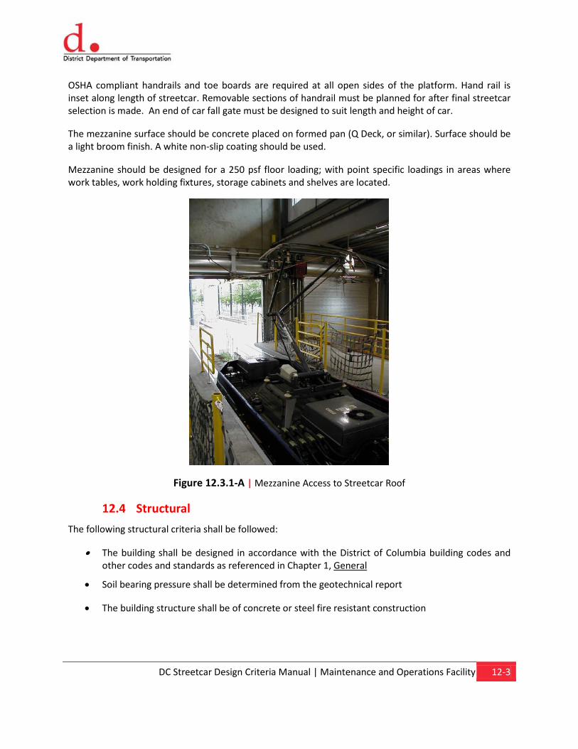
DC Streetcar Design Criteria Manual | Maintenance and Operations Facility 12-3
OSHA compliant handrails and toe boards are required at all open sides of the platform. Hand rail is inset along length of streetcar. Removable sections of handrail must be planned for after final streetcar selection is made. An end of car fall gate must be designed to suit length and height of car.
The mezzanine surface should be concrete placed on formed pan (Q Deck, or similar). Surface should be a light broom finish. A white non-slip coating should be used.
Mezzanine should be designed for a 250 psf floor loading; with point specific loadings in areas where work tables, work holding fixtures, storage cabinets and shelves are located.
Figure 12.3.1-A | Mezzanine Access to Streetcar Roof
12.4 Structural
The following structural criteria shall be followed:
• The building shall be designed in accordance with the District of Columbia building codes and other codes and standards as referenced in Chapter 1, General
• Soil bearing pressure shall be determined from the geotechnical report
• The building structure shall be of concrete or steel fire resistant construction
DC Streetcar Design Criteria Manual | Maintenance and Operations Facility 12-4
12.5 Facility Vehicle Interface
The facility designer will perform final functional layouts and define vehicle / facility interface once the manufacturer and model of the streetcar has been chosen. For purposes of this design report, a typical streetcar based on the Czech: Inekon / Skoda / OIW design, has been assumed. There are some variances between streetcar manufacturers and models. Interface points will need to be confirmed with DDOT. It will be up to the Design Build Contractor to:
• Adjust height of mezzanine to suit height of car
• Adjust horizontal clearance between side of car and mezzanine
• Confirm width of pantograph carbon and OCS contact wire offset
• Verify locations of roof-mounted components and locations of gates and removable sections of handrail
• Design end of car fall gate. Fall gate must be interlocked with the OCS to prevent the car from exiting the building with the gate closed (pantographs are very expensive to replace)
• An auxiliary power supply (connection from DC substation, to car, by cable) is used when the OCS is off and pantograph is down. This device shall be located on the mezzanine, at a location suitable to the connection point on the car
• Verify location of car jack points so that local reinforcement of the floor can be made under the powered jacks
• Verify locations of doors on car to avoid any conflicts in building and structure
• Confirm weight of car for final structural design of track supports through the inspection pit
• Verify length of car and relationship to both pit and mezzanine
• Verify OCS location and bridge crane interlocking
12.6 Corrosion Control and Safety Grounding
The maintenance facility shall have an equipotential grounding system for all conductive surfaces exposed to human contact. This shall be accomplished through use of a building perimeter ground. The perimeter ground shall be bonded to ground rods and bonded to the metal structure of the building and reinforcement bars of the concrete. The reinforcing steel of the main shop floor shall be bonded into a grid pattern and all shop conductive surfaces shall be bonded to the grid. The shop track work shall be continuous and bonded to the grid. The shop grid and perimeter ground shall be bonded to the shop substation ground mat. Insulated rail joints shall be located in the ends of the concrete aprons, which will define the extent of the shop grounding system and dc electrical system.
DC stray currents are prevalent in the yard and shop area. Accordingly, ferrous pipe shall be coated with an electrical insulating material and tested prior to burial. Some underground services (such as natural gas) may be better served by use of plastic pipe where the code allows. Joints in piping will require bonding in some locations and insulated joints in others. Refer to Chapter 14, Stray Current and Corrosion Control, of these Criteria.
DC Streetcar Design Criteria Manual | Maintenance and Operations Facility 12-5
12.7 Acoustics
In planning the new facility, noise and vibration-generating equipment such as air compressors and pumps shall be located away from office areas and/or acoustically isolated. HVAC mechanical units shall be located and specified so that noise and vibration transmission is minimized. In addition, walls, ceilings, and floors in these spaces shall be insulated to further reduce noise transmission to other parts of the facility and to the surrounding properties.
12.8 Maintenance
In planning the new facility, proposed maintenance procedures shall be reviewed and staff operations personnel shall be consulted to ensure that the new facility provides an efficient work environment. Janitorial closets and other maintenance rooms shall be located convenient for users. Floor drains, hose bibs, etc. shall be located for convenience of use.
12.9 Mechanical Systems
Pit areas shall have exhaust air ducts at side walls. Shop compressed air shall be available in all pits at convenient intervals to operate tools.
Office, administration, support, and Central Control areas shall have forced air heating, ventilating, and air conditioning systems. The HVAC system shall be designed in zones appropriate for use and exposure to heating and cooling demands. The shop substation electrical room shall be air-conditioned.
Mechanical systems shall be designed to local codes and best practices used in the local area. Follow the American Society of Heating, Refrigeration and Air Conditioning Engineers (ASHRAE) to establish HVAC loads for offices. The offices, dispatch room, break room, storeroom electrical rooms and the technical library room should be air conditioned.
The main shop building is normally heated to 65° F in the winter. This is a matter of both, employee comfort; and the workability of various car fluids, mechanical and electrical adjustments, and pliability of rubber parts (such things as changing window rubber seals become very difficult below 65° F, etc). Strictly speaking, the shop does not require refrigerated air conditioning for any technical reasons involving the streetcar. At temperatures of 100° F employee comfort may suffer, but the streetcar is not a concern. The Architect shall explore the best options and life cycle costs with the owner before finalizing any cooling and ventilation methods for the shop building.
Other Utility Requirements:
A 2” diameter compressed air loop should encircle the shop. All compressed air pipe should be schedule 40, threaded joint, A-53 ERW. Planned air drops should be made on every other building column. However, all threaded lengths of pipe shall be coupled with a tee, the blanked off (plugged) leg left pointed vertically up. All air drops shall come off the top of pipe. Maintenance pit and mezzanines require air drops on similar spacing.
Natural gas for shop and office heating should be A-53 ERW piping – All welded system, except at the point of connection to the gas train at the appliance.
DC Streetcar Design Criteria Manual | Maintenance and Operations Facility 12-6
Potable Water drops shall be located at each track door on the ground floor (total of 6). Water drops shall have hose reel with 50 feet of ½” hose.
Welding outlets shall be located on ground floor along bay lines B & C. Place two on each track end wall and two in center of facility (total of 6).
The architect will be given locations for all power, water and compressed air drops by the systems industrial engineer.
12.10 Access for the Mobility Impaired
The facility shall be designed to meet applicable federal, state and local codes for accommodating access for the mobility impaired in effect at the time of facility design. The building shall be accessible to the handicapped in compliance with the Americans with Disabilities Act, including U.S. Department of Transportation, Final Rule – Transportation for Individuals with Disabilities.
12.11 Functional requirements
The DC Streetcar Maintenance and Operations Facility shall house the following functions either in the building or on the facility’s yard area:
• Streetcar storage
• Train operator report area
• Operator and maintenance training
• Streetcar service and inspection
• Streetcar interior and exterior cleaning
• Streetcar air-conditioning, current collector and resistor unit repair
• Restrooms / Locker rooms
• Break rooms
• Fare collection (FC) equipment repair, storage and inspection
• Traction electrification system (TES) service and inspection
• Facilities maintenance
• System-wide parts storage
• Streetcar operations administration
• Streetcar maintenance administration
• Central Control
• Electronic component repair
• Communications equipment repair, storage and inspection
DC Streetcar Design Criteria Manual | Maintenance and Operations Facility 12-7
• Parking
• Storage of streetcar maintenance-of-way (MOW) materials
• Electrical substation for MOF and nearby catenary
12.12 Site Selection
The District Department of Transportation (DDOT) shall review the MOF alternatives provided by the Engineering Consultant, select the appropriate site, and if necessary, acquire the site in accordance with the Environmental Document.
The facility shall not negatively impact future development of adjacent areas.
12.13 Storage Yard
Sufficient storage tracks or space for storage tracks shall be provided to accommodate the ultimate fleet size to be stored and maintained. The storage yard shall be arranged to provide space for all streetcars to be stored on level tangent track. Area around train storage should be level to facilitate safety of workers moving around the cars. Paved storage with embedded track or ballasted track shall be used.
Track centers shall typically be 14’-0” where no access aisle is required between tracks and 17’-0” where an access aisle is required. OCS and lighting poles shall be located between tracks with 14’-0” track centers.
The layout of the storage yard shall enable movement of streetcars to and from the shop, other yard facilities, and the mainline with the smallest possible number of reverse movements and crossovers, consistent with site space limitations. This shall be accomplished by avoiding the use of stub-end tracks and by proper relationship of yard track orientation to the mainline.
12.14 Interior Cleaning Area
Cleaning of the interior of the streetcars will take place in the shop on one of the flat (no pit) car positions or in a separate sheltered area. This track will also be used to perform daily and scheduled extraordinary interior cleaning of the streetcars.
12.15 Automobile Parking and On-site Roads
Automobile parking shall be provided for visitors and employees to a level adequate to satisfy the codes and standards described in Chapter 1, General. Access for truck deliveries shall be provided.
Automobile parking should be minimized and should be balanced with current neighborhood availability and need. Employees should be encouraged to take public transportation (or modes other than the automobile) to and from work.
Adequate sheltered on-site bicycle parking shall be provided to accommodate and encourage bike ridership.

DC Streetcar Design Criteria Manual | Maintenance and Operations Facility 12-8
12.16 Outside Storage Areas
Outside storage space shall be provided for the storage of the following types of equipment and structures: OCS poles and large OCS hardware, lighting poles, rail, ties, special trackwork (such as switches, switch stands, frogs, etc.) and other track materials (such as insulated joints, etc.) Locations of these types of storage areas are not generally critical and can be fit in, as the track layout is refined.
12.17 Fire Protection System
Fire protection utilities such as hydrants, sprinklers in the building, and extinguishers shall be provided in accordance with local Fire and Rescue requirements in effect at the time of construction of the facility. The hydrants shall be located so as not to block the movement of streetcars when fire hoses are being used.
12.18 Yard Lighting
The yard shall be illuminated to provide a safe working environment for ultimate 24-hour operation of the facility. The lights shall be as energy efficient as practically possible and shall be automatically controlled by a photoelectric cell. Yard lighting shall be provided to a level of 2 foot-candles average, 4:1 average to minimum, and 9:1 maximum to minimum for the entire site. Lighting shall be shielded where practically possible so as not to spill on to neighboring properties. Lighting shall be shielded to meet Illuminating Engineering Society of North America (IESNA) certified cutoff or full-cutoff luminaries standard.
12.19 Security
Operations facility security shall be achieved by walls and fencing at the periphery of the yard and by lighting. Walls should not be continuous, but should be provided with visual openings (fencing/windows) to allow the operations of the facility to be viewed/shared with the surrounding neighborhood and visitors. Walls and fencing shall be provided, as needed, in accordance with Zoning and Historic District requirements. Gates shall be provided at all yard track and road accesses and shall provide for minimum interference to streetcar movement. Sliding (rolling) gates shall be used. Security lighting shall be placed as necessary to supplement the normal area outside work lighting. Lighting shall be shielded to meet Illuminating Engineering Society of North America (IESNA) certified cutoff or full-cutoff luminaries standard.
12.20 Refuse/Recycling Collection
Refuse/recycling collection bins, dumpsters, etc. shall be provided at several locations convenient to work areas as well as to collection vehicles. Space allocation limitations associated with the shop and yard site may require the transfer of waste and recycled materials from local collection points to a central location.
Certain containers shall be designated for recycling purposes, such as those used for metal waste, and for office waste paper, cardboard, glass, etc., and for disposal of industrial wastes.
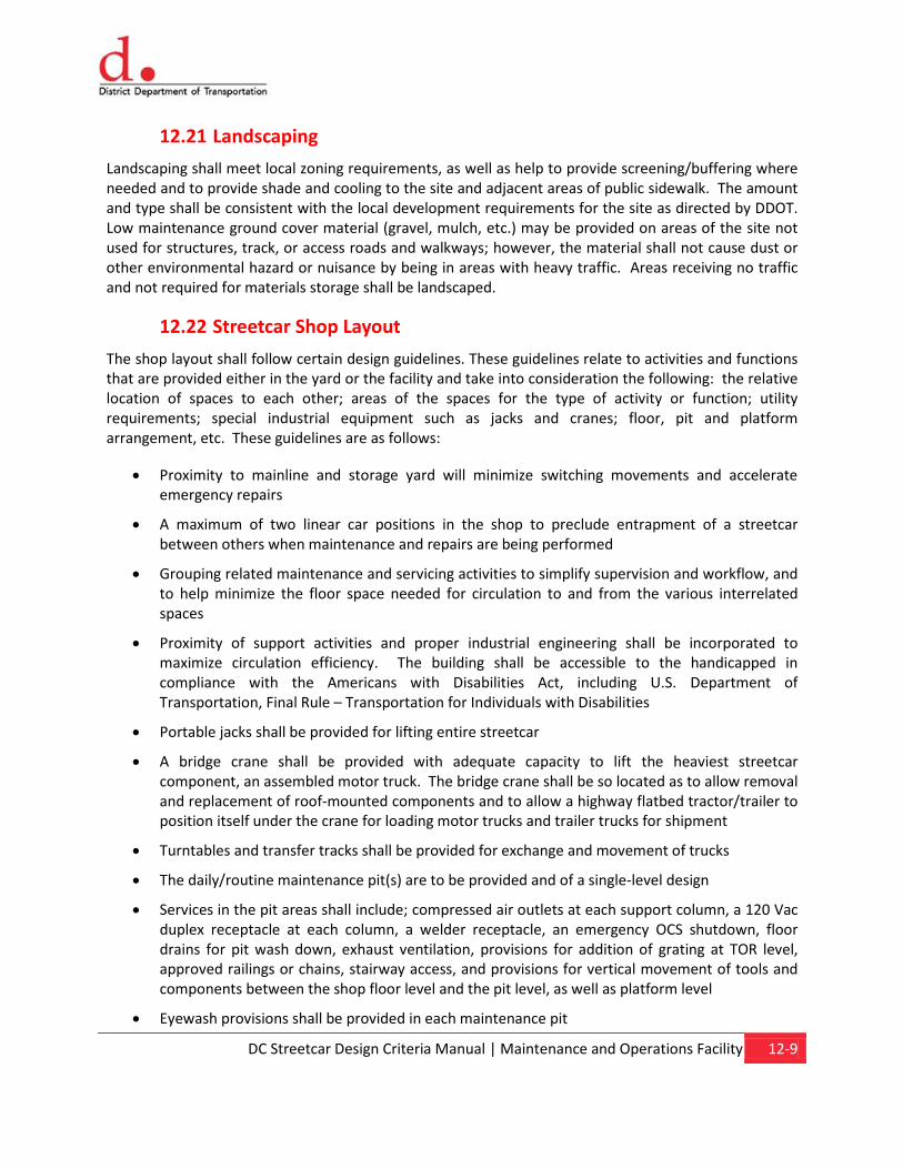
DC Streetcar Design Criteria Manual | Maintenance and Operations Facility 12-9
12.21 Landscaping
Landscaping shall meet local zoning requirements, as well as help to provide screening/buffering where needed and to provide shade and cooling to the site and adjacent areas of public sidewalk. The amount and type shall be consistent with the local development requirements for the site as directed by DDOT. Low maintenance ground cover material (gravel, mulch, etc.) may be provided on areas of the site not used for structures, track, or access roads and walkways; however, the material shall not cause dust or other environmental hazard or nuisance by being in areas with heavy traffic. Areas receiving no traffic and not required for materials storage shall be landscaped.
12.22 Streetcar Shop Layout
The shop layout shall follow certain design guidelines. These guidelines relate to activities and functions that are provided either in the yard or the facility and take into consideration the following: the relative location of spaces to each other; areas of the spaces for the type of activity or function; utility requirements; special industrial equipment such as jacks and cranes; floor, pit and platform arrangement, etc. These guidelines are as follows:
• Proximity to mainline and storage yard will minimize switching movements and accelerate emergency repairs
• A maximum of two linear car positions in the shop to preclude entrapment of a streetcar between others when maintenance and repairs are being performed
• Grouping related maintenance and servicing activities to simplify supervision and workflow, and to help minimize the floor space needed for circulation to and from the various interrelated spaces
• Proximity of support activities and proper industrial engineering shall be incorporated to maximize circulation efficiency. The building shall be accessible to the handicapped in compliance with the Americans with Disabilities Act, including U.S. Department of Transportation, Final Rule – Transportation for Individuals with Disabilities
• Portable jacks shall be provided for lifting entire streetcar
• A bridge crane shall be provided with adequate capacity to lift the heaviest streetcar component, an assembled motor truck. The bridge crane shall be so located as to allow removal and replacement of roof-mounted components and to allow a highway flatbed tractor/trailer to position itself under the crane for loading motor trucks and trailer trucks for shipment
• Turntables and transfer tracks shall be provided for exchange and movement of trucks
• The daily/routine maintenance pit(s) are to be provided and of a single-level design
• Services in the pit areas shall include; compressed air outlets at each support column, a 120 Vac duplex receptacle at each column, a welder receptacle, an emergency OCS shutdown, floor drains for pit wash down, exhaust ventilation, provisions for addition of grating at TOR level, approved railings or chains, stairway access, and provisions for vertical movement of tools and components between the shop floor level and the pit level, as well as platform level
• Eyewash provisions shall be provided in each maintenance pit
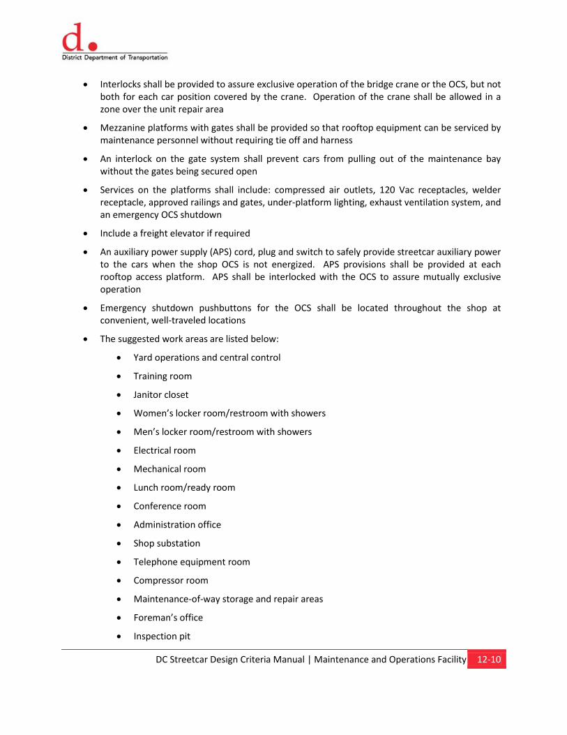
DC Streetcar Design Criteria Manual | Maintenance and Operations Facility 12-10
• Interlocks shall be provided to assure exclusive operation of the bridge crane or the OCS, but not both for each car position covered by the crane. Operation of the crane shall be allowed in a zone over the unit repair area
• Mezzanine platforms with gates shall be provided so that rooftop equipment can be serviced by maintenance personnel without requiring tie off and harness
• An interlock on the gate system shall prevent cars from pulling out of the maintenance bay without the gates being secured open
• Services on the platforms shall include: compressed air outlets, 120 Vac receptacles, welder receptacle, approved railings and gates, under-platform lighting, exhaust ventilation system, and an emergency OCS shutdown
• Include a freight elevator if required
• An auxiliary power supply (APS) cord, plug and switch to safely provide streetcar auxiliary power to the cars when the shop OCS is not energized. APS provisions shall be provided at each rooftop access platform. APS shall be interlocked with the OCS to assure mutually exclusive operation
• Emergency shutdown pushbuttons for the OCS shall be located throughout the shop at convenient, well-traveled locations
• The suggested work areas are listed below:
• Yard operations and central control
• Training room
• Janitor closet
• Women’s locker room/restroom with showers
• Men’s locker room/restroom with showers
• Electrical room
• Mechanical room
• Lunch room/ready room
• Conference room
• Administration office
• Shop substation
• Telephone equipment room
• Compressor room
• Maintenance-of-way storage and repair areas
• Foreman’s office
• Inspection pit
DC Streetcar Design Criteria Manual | Maintenance and Operations Facility 12-11
• Rooftop level maintenance platform(s)
• Spare parts storage
• Fare collection equipment repair
• Stairs/halls/lobby/elevator
• Exterior wash bay (manual wash of streetcar exterior)
Figure 12.22-A | Wide Pit
12.23 Shop Functional Areas
A bridge crane with adequate capacity to lift motor trucks shall be provided. The crane shall be located to accommodate removal and replacement (R&R) of major roof-mounted equipment. The crane shall be interlocked with the OCS as described above.
DC Streetcar Design Criteria Manual | Maintenance and Operations Facility 12-12
Figure 12.23-A | Crane in Maintenance Facility
An area for secondary repair of streetcar heating, ventilating and air conditioning equipment and other minor equipment repairs shall be provided at mezzanine platform level.
Part of the storage area shall be designated for storage of pre-dried sand, purchased in plastic-lined bags.
A fire sprinkler system shall be provided throughout the building in compliance with jurisdictional requirements. Chemical fire protection for areas such as electrical rooms, communications rooms, flammable storage, etc., may be necessary depending on local jurisdictional requirements. The system shall be held tight to the structure to avoid clearance problems.
12.24 Support Areas for Shops
The following support facilities shall be provided:
• Locker room/shower/restroom facilities for men and women
• Employee lunchroom, conference room and a training area
• Foreman’s office, storeroom facilities, and general work areas. Loading and unloading of materials for the maintenance shop shall be accommodated by assuring the bridge crane spans a flat track in the shop
• Spare parts storage
• An interior inventory storage area for wheels, trucks and other large parts and component assemblies

DC Streetcar Design Criteria Manual | Maintenance and Operations Facility 12-13
12.25 Central Maintenance, Operations and Administrative Areas
Space shall be provided for the management of the maintenance shops, operations facilities, and administration.
12.26 Exterior Streetcar Wash Facility
A car position exterior to the building shall be provided for washing the exterior of the streetcars. The car position shall accommodate single streetcars only. Infrastructure shall be provided to supply wash water and direct it to the sanitary sewer following recycling and pre-treatment as described below. The wash bay shall be enclosed and heated as necessary to effectively function in sub-freezing climate conditions.
All wash/rinse water shall be collected, treated and then discharged in accordance with applicable codes, standards and laws. Rain/storm water (on- or off-site) should be captured and stored for streetcar washing.
Equipment to recapture and/or treat wash water, including vehicle wash water recycling, and other fluids shall be provided. The recycling and reclamation system shall be capable of re-using 80% of the wash water. All wash water to be discharged shall be pre-treated to separate and remove oil products from the water and stored in a container system to be provided as part of the equipment.
12.27 Electrical Services
A separate substation shall be provided for the shop with shop tracks electrically isolated from the yard and mainline tracks. Overhead wire in the yard and over the individual shop car positions shall be sectionalized to allow the shutdown of power to the individual car positions in the shop and tracks in the yard without affecting the remainder of the shop or yard. Individual, lockable, manual disconnects shall be provided for each section isolation switch to remove traction power when required for maintenance. The shop substation will be solidly grounded to the building ground network for safety purposes.
Electrical Systems – Typical electrical design criteria for this type of facility:
The main electrical room is located on the ground floor. Service to this room starts at an outdoor pad-mounted transformer where utility service voltage is dropped to 480v AC.
Power to this facility is not expected to exceed 1500 amp at 480v.
Located within the electrical room is the AC switchgear. The AC switchgear provides isolation disconnect from the transformer; isolation disconnect to the DC substation, and isolation disconnect to the facility power distribution system.
All 3/60/480v power to shop equipment should originate from a Motor Control Center located in the electrical room. All ground floor shop equipment must be fed through underground conduit.
The DC power supply, including rectifier transformer, DC rectifier, and DC breakers and disconnects will be installed in the electrical room. Suitable high and low voltage separations must be made (the room may be divided by a sub-wall, if suitable to final equipment layout).

DC Streetcar Design Criteria Manual | Maintenance and Operations Facility 12-14
Facility grounding is critical. The facility is isolated from the DC power of the mainline and the DC power used in the storage yard, for safety reasons. Within the facility the DC system and the AC system are fully grounded. Bonding between rails, grounding of rails through the pit structure, and grounding of structures such as the mezzanine are critical. The local electrical engineer and the systems traction power engineer must collaborate on this design.
Electrical Service Requirements:
• Electric motors 1 hp and up should be 3/60/480
• Motors fractional through 3/4 hp may be single phase 115v or 240v. However, in some cases it may be advantageous to have motors 3/4 hp, and under, on 480v, 3 phase. For example, the trolley motor on the bridge crane may likely be 3/4 hp. The crane is 480v and the crane builder should keep all motors 3/60/480
• Welding Outlets: 1/60/240
• Machine Control Voltage: 1/60/120
• Lighting – Shop Areas: 1/60/277
• Lighting – Offices & Storeroom: 1/60/120
• Wall Heaters / Heating Strips: 1/60/240
• Convenience Outlets: 1/60/120
• An isolated / filtered computer 120v circuit(s) shall run in office areas and selected shop areas
Lighting Levels:
Lighting levels should be (minimum / not greater than) the following, as measured in foot-candles:
• Offices: (75 / 100) Preferred: Fluorescent Strip
• Mechanical Rooms: (50 / 75) Preferred: Fluorescent Strip
• Electrical Rooms: (50 / 75) Preferred: Fluorescent Strip
• Main Shop Floor: (75 / 100) Preferred: Hi-Bay Metal Halide*
• Above Mezzanine (150 / 200) Preferred: Metal Halide*
• Below Mezzanine (75 / 100) Preferred: Fluorescent Strip
• Pit Lighting (50 / 100) Preferred: Fluorescent Strip**
* Metal Halide Lighting should yield minimum Color Rendering Index of 90 and a Kelvin Temperature of 4200 or greater.
**Pit Lighting requires specialized fixtures designed to direct light upward, illuminating the bottom of the car.
Chapter 13Traction Power Supply Distribution
Content
13.1. General 13.2. Requirements 13.3. Traction Power Substations 13.4. DC Feeder System 13.5. Overhead Contact System 13.6. Negative Return Path and Stray
Current Control
DC Streetcar Design Criteria Manual | Traction Power Supply & Distribution 13-1
13.0 Traction Power Supply & Distribution
13.1. General
These criteria include functional and design requirements for the supply and distribution of the traction power supply system to transmit electric energy from its source to the vehicles.
The vehicles shall be propelled by electric traction motors. Energy to drive these motors will be supplied to the vehicles by rectifier substations located along the wayside through a system of distribution cables, switches and an overhead contact system (OCS) installed above each track. A pantograph will be mounted on each vehicle to serve as the interface between the vehicle and the OCS and be the collector of electrical current for the vehicles. The running rails of each track, bonds and cabling complete the path of electrical current back to the substation.
The design of the traction power distribution system shall be such that it will provide an adequate source of electrical power to the vehicles under all operating conditions. The designer shall include as part of his design goals, the safe and efficient operation of the system under many diverse conditions.
The specific subsystems of the traction power system are the utility supply feeders and switchgear, the transformer/rectifier units to convert alternating current (ac) power to direct current (dc) power, the dc distribution system, the overhead contact wire and negative return systems. The designer shall coordinate with the utility or local supplier of primary power, as well as designers of other project systems or elements, such as the vehicles, signals/traffic control, communications, civil works, etc to ensure compatibility with the traction power system.
13.2. Requirements
The following sections describe the specific elements that shall be included in the design of the traction power system.
13.2.1. Traction Power Substations
The traction power substations are the interface between the utility provided ac power and the dc distribution system. The substation shall control and rectify the utility supplied ac power to the dc power required for operation of the vehicles. The substation components will be standardized in size and configured wherever possible to minimize the inventory of parts, to allow for full compatibility and interchangeability of equipment between substations, and to facilitate the training of operations and maintenance personnel. Each substation shall include the connections from the utility ac supply to the ac switchgear through a conduit system; metering equipment; ac switchgear, ground and test device; transformer/rectifier units with primary and secondary connecting cabling and buses; dc switchgear; positive and negative buses; connections to the dc distribution system; grounding system; protective relay system; station batteries and battery charger; substation control system as well as other equipment required for a complete, safe, maintainable and efficient rectifier substation. Where required, the substation shall include a power source and feeders for the communications and signal systems. Refer to Section 13.3 for additional criteria.
DC Streetcar Design Criteria Manual | Traction Power Supply & Distribution 13-2
13.2.2. DC Feeder System
The dc feeder system consists of terminations, cabling and switching equipment to connect the traction power substation to the positive and negative distribution systems. The positive dc feeders originate from the load side of the dc switchgear and continue from the substation to the point of connection to the overhead contact system at disconnect switch contacts mounted on the top of a pole. The positive dc feeder system includes any parallel cabling necessary to maintain the minimum voltage at the pantograph with any one substation out of service or required to maintain the distribution system continuity across sections of track without an Overhead Contact System (OCS) installed. The negative return includes cabling from the traction power substation return bus to the running rails and negative return cabling installed to maintain the continuity of the negative returns across sections of track without an OCS installed.
All feeder system cabling shall be installed underground in conduits and ductbanks. Power system conduits shall be 4” diameter, organized into ductbanks and encased in red-dyed concrete. Aerial feeders or surface-mounted conduit shall not be permitted except as approved by DDOT for specific locations such as a parallel feeder on a bridge structure.
Refer to Section 13.4 for additional criteria.
13.2.3. Overhead Contact System
The overhead contact system (OCS) is defined as all electrical, mechanical and structural equipment between the vehicle pantograph and the dc positive feeder system. This includes the contact wire, all supporting structures and their foundations and guying systems (where necessary), overhead feeders, ancillary wires, hangers, insulators, conductor supports, tensioning devices, cantilever arms, sectionalizing equipment, disconnect switches, pole-mounted lightning arresters, and other items necessary for a complete system.
Refer to Section 13.5 for additional criteria.
13.2.4. Sectionalization
The system sectionalizing will be designed to enable the electrical protective relays to disconnect faulted sections, permit performance of planned maintenance, and achieve flexible operation during system emergencies.
There will be electrical continuity along the OCS system from substation to substation with sectionalizing at the substations to provide isolation of each electrical section. The sectionalizing scheme will be consistent with the location of the substations, the track layout, the signalization scheme, and proposed vehicle operations. Sectionalizing also should be considered at crossovers, other special trackwork locations, and the storage yard, for maintenance and emergency purposes.
Sectionalizing of the OCS adjacent to substations, will be performed by means of insulated overlaps on mainlines. Where overlaps cannot be located adjacent to the substations, section insulators will be used. Section insulators will also be used for sectionalizing at crossovers and turnouts.

DC Streetcar Design Criteria Manual | Traction Power Supply & Distribution 13-3
The primary connection and isolation of the system sections will be performed by the substation dc feeder circuit breakers. At locations along the route, connections and isolation of the system sections will be accomplished by manual disconnect switches.
13.2.5. Design Environment
The traction power distribution system shall be designed to operate continuously and satisfactorily under the environmental conditions described in Chapter 1, General
13.2.6. Codes and Standards
.
All materials; apparatus and equipment; and installation methods shall conform to the requirements of the latest edition of applicable AASHTO, ACI, ANSI, AREMA, ASTM, EIA, IPCEA, IEC, IEEE, NEC, NEMA, NESC, PUC, UBC, UL, and other local and state codes as defined in Chapter 1, General
13.3. Traction Power Substations
, as applicable. The designer shall consult these documents and provide a design in accordance with the most stringent code or industry practice. This document is not intended to be utilized as design guideline, but only as indication of minimum requirements.
13.3.1. General
The dc traction power shall be supplied to the OCS by traction power substations (TPSS) with a rated output of 750 volts at full load. The TPSS shall be located as close as practicable to the wayside tracks. The equipment shall be rated for extra heavy duty traction service as defined by NEMA RI-9. At rated input voltage, the maximum output voltage at 1% of full load at the substation bus shall not exceed 795 volts.
13.3.2. System Operating Requirements
The following ratings are the criteria upon which the design of the traction power distribution system shall be based:
• Nominal OCS Voltage 750 Vdc
• Maximum OCS Voltage 925 Vdc
• Vehicle Operating Voltage (Minimum) 525 Vdc
• Maximum Rail to Ground Voltage 50 Vdc normal operation
70 Vdc single TPSS outage
Vehicle minimum operating voltage should be verified against Chapter 11, Vehicle
The TPSS shall comply with IEEE 519 and not inject objectionable harmonics back into the utility supply system.
.
DC Streetcar Design Criteria Manual | Traction Power Supply & Distribution 13-4
The vehicles shall be equipped with regenerative braking. The system shall be designed for natural receptivity only, no additional means of accepting regenerative power or of feeding regenerative power to the utility shall be included.
13.3.3. Substation Location, Rating and Spacing
The traction power substations will be located at or near passenger stops whenever possible. Locations will be optimized with respect to safety, efficiency, access, availability of land or existing structures, stray current control, and minimum life cycle costs.
The TPSS designer shall provide computer simulation and modeling of the traction power system. The simulation shall model Streetcar movement over the entire system, considering vehicle propulsion system capabilities and civil alignment parameters such as passenger stops, grade, curves, and speed limits. Model dwell time at each passenger stop shall be 30 seconds. The simulation shall also provide network analysis of the wayside traction power system, considering the impedances/resistances of the transformer/rectifier units, dc feeders, and running rails. The OCS contact wire shall be modeled with 15% wear and rail with 5% wear.
During peak period operation adequate power shall be supplied to the Streetcar system for maintaining all Streetcar pantograph voltages above 525 Vdc with the required headway and loading. This level of operation shall be modeled using the computer simulation described above. The results of the computer simulation shall provide verification of the following design constraints:
• In peak period (2 hour) operation, normal operation, rms thermal loading on the rectifier transformers and rectifiers shall not exceed 100% of the equipment nameplate rating.
• In peak period (2 hour) operation, normal operation, rms thermal loading on dc breakers and buswork shall not exceed 100% of the breaker/buswork continuous rating.
• In peak period (2 hour) operation, single substation outage, rms thermal loading on the rectifier transformers and rectifiers shall not exceed 150% of the equipment nameplate rating.
• In peak period (2 hour) operation, normal operation and single substation outage, rms thermal loading on conductors shall not exceed OCS conductor ampacity. Conductor ampacity shall be determined per IEEE 738, based on ambient air temperature of 105 °F, maximum conductor temperature of 167 °F, wind speed of 2 ft/sec, coefficient of emissivity of 0.5, and coefficient of solar absorption of 0.5.
• In peak period operation, rail-to-ground voltages shall not exceed the allowable maximum rail-to-ground voltage in Section 13.3.2.
With any one substation out-of-service, one Streetcar at a passenger station shall be capable of normal rate acceleration from a start. A second Streetcar at the same passenger station may perform at a reduced operating level if starting simultaneously with the first Streetcar.
DC Streetcar Design Criteria Manual | Traction Power Supply & Distribution 13-5
13.3.4. Substation Primary Power
The local electric power vendor will supply a 480V, 3-phase, 60 Hz power supply as primary service to the Streetcar system. Methods of primary power distribution to the traction power substations will be evaluated to determine the most cost-effective capital investment and the lowest annual operating cost that can provide adequate and reliable service.
Desirably, a single utility company power source will not supply power to two adjacent traction power substations. The system will be designed so that if one power source is out of service, then a back-up source can continue to supply traction power. The service cables from the utility company source will be extended to the traction power substation. A meter and protective lightning arresters will be installed in accordance with the utility company’s regulations and standards.
13.3.5. Substation Equipment
Substations shall consist of pre-fabricated units or equipment installed in previously constructed enclosures or rooms equipped with ac switchgear, auxiliary power supply, surge arresters, transformer-rectifier units, dc power switchgear, and ventilation equipment as appropriate. The substations shall operate unattended but will be equipped with local control switches for operation of all ac and dc switchgear.
13.3.5.1. Transformer – Rectifier Units
Rectifier Transformers:
• Type and rating:
Indoor dry-type, self-cooled, designed for extra heavy duty traction service with kVA rating suitable for the specified rectifier.
• Tap Changer dry-type transformer: No-load full capacity, on the high voltage winding. Four 2.5% taps above rated voltage providing rated kVA and four 2.5% taps below rated voltage providing rated kVA. Taps shall be changed by removable links on a tap board with taps and connections identified. The tap board shall be accessible through a door key interlocked with transformer feeder breaker to prevent access to the tap board when transformer is energized.
• Bushings: In accordance with ANSI and NEMA standards for indoor interchangeable bushings. Silver plated terminal pads.
• Low Voltage Connection: Bus connections for bolted connection to ac multi-phase bus designed to align, match, connect and be compatible with the flange and busbar connections of the ac bus duct specified. Bonding strap for bonding bus enclosure to transformer case.
• Monitoring and Protective devices for dry type transformers. All contacts electrically separate. All devices shall be heavy duty industrial type.
• Winding temperature indicator, with maximum reading pointer to detect transformer winding over temperature, and with factory-set two-stage contact device. The first stage provided with a
DC Streetcar Design Criteria Manual | Traction Power Supply & Distribution 13-6
contact which opens on temperature increase to initiate annunciation. The second higher temperature stage shall be provided with two contacts; one opening on temperature increase to initiate annunciation and one closing on temperature increase to actuate the rectifier-transformer ac feeder breaker lock-out relay. Settings as recommended by the manufacturer (Devices 49T1 & 49T2)
13.3.5.2. Auxiliary Equipment
Equipment shall include lightning and surge protection, interconnecting bus work, 125 Vdc control-power battery, UPS and charger, auxiliary transformer for communication equipment, fire protection panel power, intrusion alarm system power and housekeeping power. Equipment shall include an exterior blue light that would illuminate to indicate that the substation is offline.
Interior lighting shall be provided to sufficiently illuminate the vertical faces of interior equipment such as switchgear and transformer-rectifier units. Lighting fixtures will be positioned to avoid interference with overhead wiring and shall not be located directly above switchgear, transformers, and rectifiers. The level of illumination shall be in accordance with local codes.
Exterior lighting shall be provided to sufficiently illuminate the substation enclosure and ingress/egress paths. The illumination levels shall be in accordance with local codes for outdoor lighting.
Emergency lighting consisting of rechargeable batteries and battery chargers shall be provided. A relaying device will be used to energize the emergency lamps automatically upon failure of the ac power when interior lighting is off. The battery will have the capacity to supply rated load for a minimum of 1½ hours at not less than 87.5% nominal battery voltage.
Duplex convenience power outlets will be located around the interior walls of the housing. One duplex outlet is to be located near the switchgear and rectifier, on a separate circuit and rated to permit the use of a heavy-duty vacuum cleaner or a portable air compressor.
13.3.5.3. Emergency Trip Stations
An Emergency Trip Station (ETS) shall be located in a locked box on the exterior of each TPSS. The ETS shall be used during an emergency to de-energize the entire substation by tripping the associated ac and dc feeder breakers.
13.3.5.4. Substation Grounding
The design of the grounding system shall preclude any unsafe condition for the equipment, maintenance personnel, passengers, and the general public. Each substation will be equipped with a copper ground bus and cabling connecting to a substation grounding ring. The grounding grids will consist of driven rods and conductors embedded in the earth. Grid materials shall be resistant to corrosion by the surrounding earth. The incoming feeder ground and facility ground will utilize the same substation grounding system. Non current-carrying enclosures or parts of alternating current equipment, including ac apparatus and rectifier-transformers, shall be securely connected to the grounding grid.
Enclosures for traction power rectifiers, dc switchgear, and dc busways will be insulated from ground and connected to the substation ground grid through a ground fault detection system. This system will
DC Streetcar Design Criteria Manual | Traction Power Supply & Distribution 13-7
be capable of detecting enclosure energization ("hot structure") and grounding ("grounded structure") conditions. The dc system normally will be operated without grounding. The traction power rectifier dc negative bus also will be isolated from ground.
All disconnect switches and surge arresters will be grounded. Maximum rail potential rise, step-and-touch ac and dc voltages shall not exceed the allowable values defined in the IEEE standards for ac systems and the IEC standard for dc systems.
The ground resistance of each ground grid shall be tested after installation and each ground bus when connected to ground grid, using approved test procedure. Ground mat resistance shall not exceed five ohms. Ground rod resistance shall not exceed 15 ohms. To meet resistance requirements, install additional ground rods as necessary.
13.3.5.5. Substation Enclosure
Traction power substations shall meet all local requirements for occupancy of this nature. They shall be designed to be as small as possible and still meet AISC specifications to withstand live roof loading, ice/snow loading, wind loading, and seismic. Prefabricated enclosures shall withstand the stresses caused during loading, transportation, and installation with doors, walls, and roof panels reinforced by braces, stiffeners, and/or structural members to provide a rigid module. The enclosures shall meet the following requirements:
• Emergency egress requirements and interior working spaces and clearances shall comply with NFPA 70, Article 110, both in size and arrangement. Rear access to equipment from the exterior of the enclosure shall require approval by DDOT and be limited to low maintenance components such as bus bar.
• Heating, Ventilation, and Air Conditioning shall be provided. Ventilation louvers shall prevent the entry of leaves and paper. Inlet air filters shall be installed to minimize dust accumulation within the TPSS. Roof-mounted vents shall be a low-profile, and of an aesthetically acceptable type approved by DDOT.
• HVAC system design and materials shall comply with NFPA 90A.
• The enclosure shall have provisions for temperature control. The maximum air temperature within the substation shall not exceed the design value, under maximum ambient conditions and TPSS operation at full designed capacity.
• Doors, joints, walls, roof, floor, vents, and louvers shall be rainproof under wind, rain, and snow conditions
• Metal components of the enclosure shall be grounded.
• The substation transformer shall have a maximum sound pressure level of 60 dBA at 200% full load and 50 dBA at normal load when tested in accordance with NEMA TR-1. Acoustical insulation, vibration isolation, and structural design techniques shall be used to minimize the continuous noise level of the assembled TPSS.
DC Streetcar Design Criteria Manual | Traction Power Supply & Distribution 13-8
Special architectural treatments shall be required for substations located in view of the public. The treatments shall consist of a brick masonry building with foundation to screen a pre-packaged substation or a brick masonry building into which the substation equipment is field installed. The architectural treatments shall screen all exterior mounted equipment from the view of a pedestrian and blend with the surrounding neighborhood. Substation site plans and exterior elevations shall be submitted for DDOT and community review and approval.
13.3.5.6. Circuit Breakers
Two dc circuit breakers will be provided with each substation. Circuit breakers will be installed to provide isolation of designated OCS sections and all feeders at the substations. Breakers will be equipped with direct acting instantaneous over-current, “rate-of-rise”, and automatic re-closure relaying. The protection features shall result in tripping and holding tripped of all breakers feeding a faulted circuit without the need for a transfer trip between substations.
Circuit breakers shall meet ANSI/IEEE C37.14, ANSI C37.16/16a, single-pole, single throw, air break, draw out type, with electrically controlled tripping, mechanically and electrically trip-free, complying with applicable parameters in Table 11 of ANSI C37.16a. The racking mechanism shall have connected, test and disconnected positions; manually operated closed-door mechanism by preventing over travel, guides for alignment of breaker with stationary unit and an indicator to show breaker position within the compartment. Feeder breaker shall have a series trip device, direct acting, direct release, forward and reverse (bi-directional), series trip device adjustable between 200% and 400% of circuit breaker continuous current rating. The circuit breaker shall have control switch on each circuit breaker for electrical closing and tripping of the breaker.
13.3.5.7. Interconnecting Buses
Interconnecting buses shall be sized on the basis of ANSI standards and shall be supported to withstand available short-circuit current at the appropriate bus-voltage level. Buses shall be constructed of ASTM B187, 98% conductivity copper with a maximum current density of 800 amperes per square inch.
The buses shall be capable of withstanding mechanical stresses and heat due to maximum short-circuit current. Bare buses shall be mounted on barrier type insulation or post type insulators of sufficient strength to withstand without damage or permanent distortion all stresses produced by short-circuit current equal to the interrupting rating of the circuit breakers.
Bus contact surfaces shall be silver-plated or tin-plated at connections. Each joint shall have an impedance of not more than that of a bus bar of the same length, clamped to maintain that impedance throughout the life of the equipment and treated to prevent corrosion. All connections to bus made with cadmium plated, galvanized or similarly coated, high strength steel bolts of sufficient number and size to provide solidly bolted connections.
13.3.5.8. Feeder Supports
Traction power positive cables from the dc feeder breaker connections and negative cables from the negative bus connections shall be laid in separate raceways. Raceways shall be non-metallic and have adequate cross-sectional area to permit a neat alignment of the cables without crossing and twisting. The feeder supports shall be designed in accordance with NEC requirements.
DC Streetcar Design Criteria Manual | Traction Power Supply & Distribution 13-9
13.4. DC Feeder System
13.4.1. General
The dc feeder system shall consist of the cables and conduit necessary to distribute dc power from the TPSS to the OCS and the return from the running rails. The feeder system shall be divided into two sections, the positive and negative feeder system. Feeder systems shall consist of insulated copper conductors conforming to ASTM and ICEA standards, and the conduit system, consisting of ducts and manholes shall conform to NEC requirements.
13.4.2. Positive Feeders
The positive feeder system is the cable that connects the dc feeder breaker to the interface point with the OCS.
13.4.3. Negative Feeders
The negative feeder system is the dc feeder cable from the rails to the negative bus in the substation.
13.4.4. Cables
Traction power feeder cables shall be standardized with 2 kV insulation and be based on a single conductor size which shall accept normal, maximum overload and short-circuit currents not exceeding the safe insulation design limits of the cable. Multiple cables shall be used to meet different current requirements. The feeders’ size shall be such that voltage drops in the feeders do not affect the required traction power voltage levels under normal and overload conditions and to operate at the rated insulation temperature during normal operating conditions.
Where cables are installed in exposed locations, a means shall be provided to support the cables adequately. Lightning protection shall be provided at points where cables enter or leave underground conduit systems.
13.4.5. Conduit Systems
Feeder ductbanks shall consist of fiberglass reinforced epoxy duct or Schedule 40 PVC conduit encased in red-dyed concrete. Design requirements for the ductbanks, such as conduit size, maximum total turns (in angular degrees), and the minimum embedment depth below grade, the manhole spacing, and the duct gradient shall be in accordance with the NEC. All buried feeder ductbanks shall be identified by a detectable yellow warning tape six inches wide marked "Warning - High Voltage" laid in backfill 12 inches (300 mm) above the concrete encasement.
Ductbanks shall be installed to run as directly as possible between terminations with care to avoid other ducts, pipelines, sewers, foundations, etc. Ductbanks shall also be run as gradual as possible in the horizontal and vertical planes to avoid deformation of the ducts. Manholes, pull-boxes and hand-holes, as required, shall be located to facilitate installation of the cables. The number of ducts installed shall have a 20% spare capacity, with a minimum of one duct for future installation, where possible.
DC Streetcar Design Criteria Manual | Traction Power Supply & Distribution 13-10
13.5. Overhead Contact System
13.5.1. General
The overhead contact system (OCS) includes the contact wire system and the physical support system. Technical, operational, maintenance, local climatic and economic considerations will be the basis of design of the OCS, as well as, the environmental conditions discussed in Chapter 1, General
The OCS consists of the conductors, including the contact wire, in-span fittings, jumpers, conductor terminations, and associated hardware from which the vehicle draws power by means of the physical contact of the pantograph on the contact wire. Design of the OCS shall be interfaced with the vehicle dynamic performance characteristics and track geometry in order to develop a system where the pantograph maintains contact with the contact wire for proper current collection under all operating conditions; see Chapter 11,
.
Vehicle
The physical support system consists of foundations, poles or masts, guys, insulators, brackets, cantilevers, and other assemblies and components necessary to support the OCS so that contact will be maintained during all operating conditions. The support system will be double insulated throughout the OCS.
.
The feeder system consists of the feeder conductors, jumpers, switches, and associated hardware that connect the TPSS dc positive feeders to the contact wire.
The traction power distribution system shall be electrically continuous from substation to substation. At the TPSS, the OCS system continuity shall be sectionalized to isolate each electrical section. An arrangement providing continuity and flexibility for sectionalization of the OCS while any track is out of service shall be incorporated in the design. Sectionalization at switches or other special trackwork locations, as well as in the yard, is required to provide operations and maintenance flexibility.
At locations where insulated separation in the contact wire is required, such as at special trackwork, jumpers, switches and breakers will be employed to maintain electrical continuity. Where jumpers are used, they shall be sized to provide the same amp capacity as the contact system.
13.5.2. Overhead Contact System Configuration
13.5.2.1. Mainline Sections
The OCS shall be designed to suit aesthetic requirements of the area. This OCS style will consist of an auto tensioned single contact wire (ATSCW) located over each track.
The OCS in streets shall be supported and registered by means of cantilever assemblies. Cantilever arrangements may be required to reach over street parking lanes. Where cantilevers are not appropriate, support and registration shall be by means of span wires. Center poles will be used where the tracks are adjacent to center roadway median strips.
The use of overhead contact system poles along streets should be kept to a minimum. Where new street lighting is proposed, the design of joint use poles will be coordinated with street lighting designers.
DC Streetcar Design Criteria Manual | Traction Power Supply & Distribution 13-11
Wherever possible to reduce clutter along streets, the overhead contact system will be attached to existing structures, buildings, traffic signal poles, and street light poles provided these supports are structurally suitable.
Wire termination or anchor poles will be designed for use without use of guy assemblies.
13.5.2.2. Mainline Tunnel or Roofed Sections
Within route sections covered by tunnel or roof, the OCS style will consist of a single contact wire located over each track, and where required, supplemented by along-track paralleling feeder cables. The single contact wire will be auto tensioned where technically possible.
The overhead contact system will be supported by a direct insulated attachment to the ceiling, to the soffit of the overhead structure or from adjacent wall structures. The contact wire will be registered by service proven resilient support arms. Service proven conductor rail systems may be submitted for approval as an alternative design. Limited clearance conditions may require a close spacing of supports to minimize the depth of the attached system.
13.5.2.3. Vehicle Maintenance and Storage Facilities
A fixed termination single contact wire (FTSCW) style of overhead contact system will be used for storage facility yard tracks. Poles supporting contact wire terminations will be designed to accommodate the variance in conductor tension due to climatic change.
The OCS in the storage areas shall be supported and registered by means of cantilever assemblies. Where cantilevers are not appropriate, support and registration will be by means of head span wires and steady span wires.
Where OCS wiring enters vehicle maintenance shops where it will be normal practice for staff to access vehicle roof equipment, permanent equipment will be required to safely isolate and ground each wired track individually. Such equipment will be designed to facilitate safety lockout and interlocking procedures used by the shop staff.
Non-bridging section insulators will be required in contact wires entering vehicle maintenance buildings. Typically these will be located outdoors above the edge of the concrete apron surrounding the building. Specifically, they are required to be located above the midway point between any pairs of insulated rail joints cut into the track for ground system isolation purposes.
13.5.3. Design Coordination
The OCS shall be designed in accordance with the criteria in Chapter 3, Track Alignment and Vehicle Clearance; Chapter 9, Trackwork; and Chapter 11, Vehicle.
DC Streetcar Design Criteria Manual | Traction Power Supply & Distribution 13-12
13.5.4. Design Parameters
13.5.4.1. Environmental Conditions
The OCS design should account for the following Operating Conditions and Non-Operating Conditions.
13.5.4.1.1. Operation Condition
Operating Condition is defined as the extreme combination of environmental values within which the OCS is to be available for normally operating rail vehicles. Two combinations are defined. Calculations will consider both, and utilize the most onerous condition.
Operating Condition 1 is the concurrence of ¼ inch (6 mm) of radial ice cover, 40 mph (65 km/h) of wind, and temperature of -5 °F (-20.5°C).
Operation Condition 2 is the concurrence of no ice cover, 55 mph (88 km/h) wind, and temperature of -5 °F (-20.5 °C).
13.5.4.1.2. Non-Operation Condition
Non-Operating Conditions will be applied to design calculations for structural and strength purposes for equipment, conductors and parts. Unless covered by superior requirements of other relevant codes, OCS equipment and conductors will be designed to meet the structural and strength requirements of National Electrical Safety Code.
13.5.4.1.3. Safety Factors
Unless covered by superior requirements of relevant codes, the following minimum equipment and conductor strengths are to be applied to the design:
Tensioned Conductors:
Operating Condition 2.0
Non-Operating Condition 1.6
Structures, hardware and non-electrical wires:
Operating Condition, against breakage 2.5
Operating Condition, against slippage 2.5
Non-Operating Condition, against breakage 2.0
Non-Operating Condition, against slippage 2.0

DC Streetcar Design Criteria Manual | Traction Power Supply & Distribution 13-13
13.5.4.1.4. Pantograph Data
The OCS will be designed to suit pantographs operating with the following dimensions;
Minimum Collector Head Width from horn tip to horn tip 66.1 inches (1680 mm)
Maximum Collector Head Width from horn tip to horn tip 73.0 inches (1030 mm)
Minimum Length of Carbon Collector 40.6 inches (300 mm)
Maximum Collector Head Width 15.7 inches (400 mm)
Maximum Unworn Carbon Collector Radius 26 feet (8.5 m)
Maximum Pantograph Sway relative to vehicle body 1.5 inches (37 mm)
13.5.4.1.5. Pantograph Security
Minimum Pantograph Security (Residual Width) 3 inches (75mm)
13.5.5. System Design Study
The design of the overhead contact system will be based on an engineering study. The study will include calculations and development of the system design parameters. It will take into account all factors that contribute to displacement of the contact wire with respect to the pantograph, including:
• Climate condition
• Conductor data
• Pantograph security
• Conductor stagger
• Mast deflection due to static and live imposed loads
• Poles installation tolerances
• Vehicle roll and lateral displacement
• Sway of pantograph
• Track maintenance tolerances
The result of this study shall define and provide values for the following parameters, where they have not been specified herein:
• Maximum structure spacing as a function of track curvature and vertical profile
• Conductor blow-off, stagger effect and allowable static offset
DC Streetcar Design Criteria Manual | Traction Power Supply & Distribution 13-14
• Maximum stagger on tangent track, and on curved track
• Conductor rise and fall under various climatic combinations
• Conductor along-track movement, and wire elongation
• Conductor tensions, sags and factors of safety under various climate conditions
• Contact wire stagger deviation due to movement of hinged cantilevers
• Conductor profile, hanger lengths and spacing
• Equipment vertical and radial loads
• Loss of conductor tension along the system
13.5.5.1. Clearances and Tolerances
The normal minimum and absolute minimum static and passing clearances will be maintained between live conductors, OCS equipment, including the pantograph and any grounded fixed structures, in accordance with AREMA Manual for Railway Engineering, Chapter 33, Part 2 as applicable to Light Rail Transit Cars.
For vehicle related clearances, full allowance shall be included for the dynamic envelope of the vehicle under operating conditions, including track and other maintenance tolerances.
Absolute Minimum Passing or Static clearance values shall not be used for design purposes.
13.5.5.2. Pantograph Clearance Envelope
A pantograph clearance envelope shall be developed for applications on all tracks for worst case conditions. Erection tolerance components are to be included for all surfaces involved in each clearance summation.
Horizontal clearance components will include a full vehicle roll plus a 6 inch mechanical running clearance.
Vertical clearance component dimensions will include minimum static clearance or passing clearances plus dynamic uplift; which ever is more onerous and appropriate for that situation.
No equipment, except the OCS steady arm end attached to the in-running contact wire, shall intrude into the pantograph clearance envelope, when the contact wire is in its static position or dynamically uplifted position. The heel end of all steady arms will be outside the pantograph clearance envelope.
13.5.6. Single Contact Wire Auto Tensioned Style Wiring
The system on tangent track streets shall be supported and registered by means of single cross-span head span wires designed to accommodate along track movement or hinged cantilevers. At sharp curves and corners, wire pulloff assemblies may be used. The contact wire shall be staggered.
DC Streetcar Design Criteria Manual | Traction Power Supply & Distribution 13-15
The single contact wire auto tensioned style wiring shall consist of a number of tension sections. Each tension section shall be designed as long as possible considering the mechanical constraints of the system design, such as displacement of contact wire due to swinging cantilevers, tension loss along the system, balance weight travel and manufacturing limits of conductor length. Further, the tension section design shall take into account the electrical sectioning requirements.
Tension lengths shall be terminated at each end by auto-tensioning devices or fixed terminations. Where tension sections have an auto-tensioning device at both ends, the possibility of wire travel along track will be addressed in the design.
Where route sections are not divisible into full tension sections, or are over steeply graded sections of track, half tensions sections will be permissible in the design. Half tension sections are where one end of the wiring utilizes a fixed termination and the other end a balance weight anchor assembly. Where half tension sections are employed on steep grades, the fixed termination will be installed at the higher level.
13.5.7. Single Contact Wire Fixed Termination Style Wiring
At operations facilities and designated tracks junctions, single contact wire fixed termination style wiring shall be used.
The wiring shall be supported and registered by means of cantilevers or single cross-span head span wires. At sharp curves and corners, wire pulloff assemblies may be used. The contact wire shall be staggered.
13.5.8. Adjacent Overhead Contact System Styles
Tension sections shall each be designed to be wholly of a single style. Where two tension lengths of different styles abut at an overlap or cross at a turnout, the equipments and fittings shall be designed for smooth operation of pantograph under the possible climatic variations
13.5.9. Tensioning Devices
Tensioning devices shall accommodate conductor expansion and contraction and shall be provided with broken wire restraint arrangements. All operating wires shall be of flexible, non-rotating stainless steel wire. Devices will have features that limit wire travel between two field-adjustable stops.
Balance weight anchors are the preferred auto-tensioning device. Balance weight anchor assemblies shall tension using cast iron, or steel balance weights.
In designated city streets, balance weight assemblies are to be installed inside tubular poles. The pole will have inspection holes with vandal resistant covers capable of removal for maintenance inspections of the weight position and internal moving parts. Poles and assemblies will be designed such that weights and other parts can be maintained or replaced with the pole in place.
Balance weights shall be positioned to be as unobtrusive as possible. In areas where external balance weights are permitted, and are frequented by passengers or pedestrians, the balance weight assembly
DC Streetcar Design Criteria Manual | Traction Power Supply & Distribution 13-16
shall be provided with a protective shield. The shield shall be vandal resistant, and be capable of removal or opening for maintenance inspections of the weight position and internal moving parts.
Spring tensioning devices may be used for very short tension sections servicing crossover or yard lead tracks, and where every span in the tension length is less than 80 feet long. Separate spring tensioners are required for each contact wire.
Pneumatic, hydraulic or gas tensioning devices shall not be used.
13.5.10. Contact Wire Height and Gradient
The design of the overhead contact system shall include consideration of the pantograph lock-down height and the height of existing overhead obstructions. The contact wire at supports shall be designed to take into consideration the effect of wire sag due to temperature rise and installation tolerances, including track construction and maintenance tolerances.
Different conditions may exist along the route, for which applicable heights measured from top of the rail at maximum operating temperature and no wind, are required as shown below.
Table 13.5.10-A |Contact Wire Height and Gradient
Condition Minimum Permissible
Contact Wire Height at
Normal Contact
Wire height at Support for Single
Exclusive right of way 16’ – 0” 19’ – 6”
Semi exclusive right-
of-way (shared with
other vehicles).
18’ – 0” 19 ’- 6”
Maintenance
Building
18’ – 0” 19’ – 6”
Storage tracks 18’ – 0” 19’ – 6”
Under no circumstances shall the contact wire height exceed 20.0 feet.
The maximum contact wire gradient shall not exceed 1 in 5 times the line segment vehicle speed in miles per hour. Changes in gradient shall not exceed one-half of this value.
13.5.11. Overhead Contact System Conductors
The contact wire shall be 350 kcmil solid grooved hard-drawn copper, conforming to ASTM Specification B47.
Wire size shall be confirmed by traction power simulation.
DC Streetcar Design Criteria Manual | Traction Power Supply & Distribution 13-17
A 30% cross-sectional area of contact wire loss due to wear and the effect of temperature change on all conductors shall be considered in the design of conductor tension.
Full current jumpers shall be used to maintain electrical continuity at special trackwork locations and overlap spans where it is necessary to have a physical separation of conductors. All jumper wire shall be of stranding class G or higher. Jumper assemblies and methods shall have sufficient conductivity for the OCS circuit ampacity.
13.5.12. Registration Loads and Angles
Steady arm assemblies registering the contact wire shall have the following category names and limitations applied.
• Light Load: Radial load up to 200 lb pull or 80 lb direct push on a steady arm
• Medium Load: Radial load up to 500 lb pull on a steady arm
• Heavy Load: Radial load up to 1000 lb shared by a double medium load steady arm assembly
Direct push arrangements shall not be applied to in-running contact wires where push off radial load exceeds 80 lb.
The angle of deviation of the contact wire due to any one in-running steady arm shall not exceed 14 degrees.
13.5.13. Overlaps, Crossovers and Turnouts
Overlaps shall be used between adjacent tension sections to provide mechanical continuity of the OCS and to permit smooth passage of the Streetcar pantograph from one tension segment to another. One span overlaps are preferred. Un-insulated one span overlaps shall be designed to permit future installation of insulation. Two span un-insulated overlaps may be located on circular curves. Overlaps shall not be built over spiral transition curves in trackwork.
Crossovers and turnouts shall be used at track special work locations where the Streetcars change tracks and yard leads where they leave or enter the mainline. Crossover or turnout wire shall be arranged to cross with the mainline contact wire underneath. Assemblies shall be designed to restrict the relative vertical movement of the two contact wires, yet permit along track movement. Full current jumpers shall connect the two wires within the crossing span.
The overlap, crossover, and turnout arrangements shall be designed considering the electrical and mechanical properties of the OCS. The designs shall enable a uniform uplift of the contact wires of each system with no hard spots. A smooth pantograph passage and good current collection without arcing shall be achieved under all operating conditions.
Sufficient electrical and mechanical clearances shall be maintained between adjacent cantilevers and between the cantilever frames and adjacent conductors. In auto-tensioned segments the clearances shall allow for the cantilevers attached to adjacent sections to move in opposite directions as the temperature changes without infringing clearances or causing misalignment of the system.
DC Streetcar Design Criteria Manual | Traction Power Supply & Distribution 13-18
The overlap, crossover, and turnout arrangements shall be designed using single poles with twin cantilevers. Only where this arrangement is not possible two poles with one cantilever each may be used.
In areas where center poles are used, the overlaps shall be staggered along the track to reduce pole loading.
13.5.14. Poles and Foundations
All poles shall be manufactured from steel and be designed as free standing, except guyed termination poles may be used in specific locations with DDOT approval. The quantity of pole types shall be minimized.
All poles shall have a base plate drilled to fit the foundation bolt pattern and be dimensioned to prevent poles being installed on a lower strength foundation. Where a functionally equal pole style of equal strength exists within the DDOT standard range of poles, new pole designs shall be suitable for installation on foundations suitable for DDOT standard poles.
Poles shall be designed so that under all operating conditions the across-track live load deflection of any structure shall be no more than one inch in either direction laterally at contact wire height. Pole designs shall account for the impacts of track center and clearance calculations.
All poles shall have provision for grounding or bonding conductor connections.
Pole foundations located in pedestrian areas such as sidewalks shall be recessed. The pole base and anchor bolts shall be covered with a lean concrete mixture to match the adjacent area such that a smooth surface is provided. The lean concrete shall be removable for purposes of pole replacement.
On designated streets, poles may be required to be of an ornamental style, to provide for joint use with street lighting or traffic services, or be suitable for the internal installation of balance weight assemblies.
The design of foundations for support poles and guy anchors shall be based on the structure loading calculations and soil data. The supporting structure foundations shall be designed to accept bolted base poles and have provision for internal feeder conduits and pole grounding rods, wires, and fittings. Foundations shall be designed to match the maximum loads permitted for the attached type of pole or guy assembly.
13.5.15. OCS Grounding and Bonding
All OCS support structures and support assemblies shall be effectively grounded and bonded in accordance with NEC and in accordance with the requirements of Chapter 14, Stray Current and Corrosion Control
13.6. Negative Return Path and Stray Current Control
.
Running rails shall be of the continuous welded type. Where it is necessary to have a bolted connection, the bolted joints shall be electrically bonded.
DC Streetcar Design Criteria Manual | Traction Power Supply & Distribution 13-19
Insulated joints shall be installed at the entrance to the shop buildings to prevent any connection between the traction power system in the shop and on the main line. In each track the pair of insulated rail joints shall not be located at the same stationed locations. The locations shall be staggered such that at least two axles of the Streetcar have a current return to each traction power circuit at the point where the Streetcar pantograph crosses the OCS section insulator. Such locations are to be valid for all types of rail vehicles in operation, and with these vehicles facing either direction.
The traction power distribution system designer, as well as other designers, shall employ designs that will mitigate stray currents and to provide means of monitoring any potential stray current conditions. As a minimum, the following measures shall be employed to mitigate stray current conditions. Running rails shall be isolated to the extent practical from ground. The mainline traction power system shall be isolated from the shop traction power systems. All traction power distribution system design shall be coordinated with Chapter 14, Stray Current and Corrosion Control
Applicable Standard Drawings:
.
OCT-01 General Notes for OCS Drawings OCT-02 Abbreviations Used on OCS Drawings OCT-03 Vertical Electrical Clearance for non-OCS Wires OCT-04 Vertical Electrical Clearance Requirements OCT-05 Summary of Design Criteria, Tolerance, and Wire Heights OCT-06 Pantograph Collector Outline OCT-07 Simplified Pantograph Clearance OCT-08 Pantograph Clearance to Ground Items and Different Electrical Circuits OCT-09 Pantograph Clearance to Live OCS Fittings OCT-10 Steady Arm Clearances and Dimensions OCT-11 Conductor Particulars OCT-12 Auto and Fixed - Tensioned Single Contact
Wire Span Length Chart OCT-13 Auto - Tensioned Single Contact Wire - Along
Track Movement and Stagger Change OCT-14 Auto - Tensioned Single Contact Wire Radial and Wind Loads OCT-15 Fixed - Tensioned Single Contact Wire Radial and Wind Loads OCT-16 Swat And SWFT Erection Tensions OCP-01 Sample OCS Wiring Layout Plan OCP-02 Sample Pole and Foundation Schedule OCP-03 Sample Acceptance Measurement Requirements OCD-01 Typical Cantilever and Supported Pull-Off Structures - Swat OCD-02 Typical Headspan Structure - Swat OCD-03 Typical Cross Span Structure - Swat OCD-04 Typical Feeder Structures With Disconnect Switch OCD-05 Typical Section Insulator Suspension Structure - Swat OCD-06 Midpoint Anchors OCD-07 Insulated Overlap on Headspan Support Structures OCD-08 Insulated Overlap on Cantilever Support Structures
DC Streetcar Design Criteria Manual | Traction Power Supply & Distribution 13-20
OCD-09 Bracket Assemblies for Tubular Poles - Types BA, BB, BC, BD, BE, and BH
OCD-10 Single Contact Wire Light/Medium Push-Off and Pull-Off, Cantilever Assemblies CA-01l/M and CA-02l/M
OCD-11 Single Contact Wire Heavy Push-Off and Pull-Off, Cantilever Assemblies CA-01H and CA-02H
OCD-12 Single Contact Wire Insulator Support, Cantilever Assembly CA-03 OCD-13 Single Contact Wire Out-Of-Running, Cantilever Assembly CA-04 OCD-14 Single Contact Wire Two Track Cantilever Assembly CA-05 OCD-15 Single Contact Wire Push and Pull Cantilever Attached To Balance Weight Pole CA-06
and CA-07 OCD-16 Bridle Wire Assemblies, Types BD-1, BD-2, and BD-3 OCD-17 Medium and Heavy Pull Off Assemblies, POP-1M, POP-2M, and Pop-3H OCD-18 Headspan and Cross Span Support Assemblies - Type HS-1 OCD-19 Headspan Regisration Assemblies - Type HR OCD-20 Midpoint Guy Assembly - Type MP-1 OCD-21 Balance Weight Anchor Assembly - Type BW-01 OCD-22 Fixed Termination Assemble - Type FA-1 OCD-23 Jumper Assembly - Type JC, Cross Contact Assembly - Type CC OCD-24 Section Insulator Assembly - Type SI OCD-25 Cut-In Insulation Assemblies and Splice Types - IN2C, IN2G, IN3, and SP1 OCD-26 Pole Mounted Disconnect Switch Assembly - Type DS-21 and DS-22 OCD-27 Surge Arrester Assembly - Type SA OCD-28 Foundation and Pole Ground Connection Assembly - Type PG OCD-29 Shop Door Bridge Assembly - Type SD-1 OCD-30 Shop Door Wire Termination Assemblies - Type SY-1 and SY-2 OCD-31 Typical Shop Door Wire Termination Brackets OCD-32 Tapered Tubular Pole Assemblies - Type PS and PF OCD-33 Tapered Tubular Feeder Pole Assembly Type PF OCD-34 Tubular Balance Weight Anchor Pole Assembly Types PB4
Chapter 14 Stray Current and Corrosion Control
Content
14.1. Purpose 14.2. Scope 14.3. Interfaces 14.4. Applicability of Criteria 14.5. Expansion Capability 14.6. Standards and Codes 14.7. Special Design Provisions 14.8. Stray Current Corrosion Prevention 14.9. Stray Current Corrosion Prevention Systems 14.10. Soil Corrosion Control (Buried Structures) 14.11. Soil Corrosion Prevention Systems 14.12. Atmospheric Corrosion Prevention 14.13. Atmospheric Corrosion Prevention Systems 14.14. Grounding 14.15. Design and Coordination of Grounding
Systems
DC Streetcar Design Criteria Manual | Stray Current and Corrosion Control 14-1
14.0 Stray Current and Corrosion Control This chapter shall apply to corrosion control design for underground metallic structures and pipes, storage facilities, and any other facilities where corrosive conditions can occur due to stray dc current. Types of corrosion control include stray current mitigation, protective coating, and cathodic protection.
14.1. PURPOSE
These criteria describe design requirements necessary to accomplish corrosion control measures for all rail transit projects utilizing electric traction power. Design factors to consider for each system include plans to minimize stray current at the source, prevent premature failures of transit facilities, and other underground structures to be installed, operated, and maintained in a cost effective manner. Corrosion control requirements shall be coordinated with all applicable engineering disciplines, and the standards and codes requirements referenced in Chapter 1, General.
14.2. SCOPE
14.2.1. General
These criteria are separated into three areas, namely stray current corrosion control, soil corrosion control, and atmospheric corrosion control. The design criteria for each of these categories and its implementation shall meet the following objectives:
• Realize the design life of transit facilities by avoiding premature failure caused by corrosion
• Minimize annual operating and maintenance costs associated with material deterioration
• Ensure continuity of operations by reducing or eliminating corrosion related failures of transit facilities and subsystems
• Minimize detrimental effects to facilities belonging to others as may be caused by stray earth currents from transit operations
14.2.2. Stray Current Corrosion Control
Stray current control shall be based on the following principals:
• Increasing the conductivity of the return circuit
• Increasing the resistance between the return circuit and the earth
• Increasing the resistance between the earth and underground metallic structures
• Increasing the resistance of underground metallic structures
Stray current control measures shall be installed on traction power and track systems to obtain minimal flow of dc stray current into the surrounding environment. Protection measures shall be applied to assure that stray earth currents are maintained within acceptable ranges to avoid deterioration of
DC Streetcar Design Criteria Manual | Stray Current and Corrosion Control 14-2
buried metallic structures. Data shall be obtained during Baseline Stray Current Survey to determine effects/magnitude of stray currents, if present, on existing utility installations, and to serve as a documented reference for future investigations.
14.2.3. Soil Corrosion Control
Soil and ground water corrosive characteristics shall be determined and documented during the Baseline Stray Current Surveys and from the Geotechnical Survey Report. Analysis of the data obtained, or from supplemental on-site measurements, shall be the basis for corrosion control designs. Structures shall be protected against the environmental conditions by use of coatings, insulation, cathodic protection, and electrical continuity as appropriate.
14.2.4. Atmospheric Corrosion Control
The atmospheric corrosion conditions such as temperature, relative humidity, wind direction and velocity, solar radiation, and amount of rainfall shall be determined during the Baseline Stray Current Survey. The areas with corrosive atmospheres (industrial, marine, rural, etc.) shall be identified. Materials selection, designs, and associated coatings shall be based on recommendations of the survey and shall be used to prevent metallic structures and hardware from atmospheric corrosion.
14.2.5. Grounding
Due to the natural difference between safety grounding and corrosion control requirements, the guidelines provided in these criteria shall be followed. Grounding designs for traction power substations, passenger stations, shops and yards, aerial structures, and other wayside locations, shall be reviewed by corrosion control personnel to assure corrosion control designs are not compromised.
14.3. INTERFACES
Corrosion control shall be interfaced and coordinated with other engineering disciplines and designs, including the utility, mechanical, civil, structural, electrical, trackwork, traction electrification, environmental, geotechnical, architectural, signals, communications, and safety and security designs.
14.4. APPLICABILITY OF CRITERIA
Since the DC Streetcar Program may be designed and constructed in segments, corrosion control criteria shall be applicable throughout the design, installation, and start-up process of all segments.
14.5. EXPANSION CAPABILITY
Corrosion control systems shall be easily expandable to the entire system without major reconfiguration, reconstruction, redundancy, and duplication of equipment. Experimental designs, equipment, and prototypes of a research nature are discouraged and must be reviewed and approved by the Engineer prior to their implementation and prior to incurring any costs.
14.6. STANDARDS AND CODES
Standards, codes, and recommended practices for corrosion control shall include, but not be limited to the following publications and/or codes by:
DC Streetcar Design Criteria Manual | Stray Current and Corrosion Control 14-3
• The National Association of Corrosion Engineers International
• National Fire Protection Association
• American National Standard Institute
• American Standards for Testing Materials
• American Water Works Association
• American Electric Railway Association
• Department of Transportation
• Steel Structures Painting Council
• Institute of Electrical and Electronic Engineers
• Underwriters Laboratories, Inc
• The Occupational Safety and Health Act
• National Electrical Code
• Military Specifications
• National Electrical Manufacturer's Association
• National Electrical Safety Code
Local and state codes may also apply, for additional requirements, see Chapter 1, General. Designers shall consult these publications and provide systems in accordance with the most stringent applicable code, or industry practice.
14.7. SPECIAL DESIGN PROVISIONS
During the design phase of the project, the corrosion control designer shall identify unique and special design cases such as existing building foundations, parallel power lines, and unusual soil conditions. In these cases, the corrosion control designer shall evaluate and recommend special design measures as appropriate.
14.8. STRAY CURRENT CORROSION PREVENTION
14.8.1. Purpose
The purpose of this section is to provide criteria for designs to minimize the corrosion impact of stray currents from the transit system which would impact transit system structures and adjacent structures. By the application of the appropriate design criteria, the magnitude of stray currents can be reduced to such low levels that their corrosive effect on buried structures is negligible. The basic requirements for stray current control are as follows:
Under normal conditions, operate the transit system without direct or indirect electrical connections between both the positive or negative traction power distribution circuits and ground.
DC Streetcar Design Criteria Manual | Stray Current and Corrosion Control 14-4
Traction power and the trackwork shall be designed to minimize stray currents during normal revenue operations.
14.8.2. Scope
Structures and systems that may be affected by stray currents shall be identified. Typically these include, but are not limited to:
• Trackwork components
• Traction electrification system components
• Metallic pipes and casings
• Reinforced concrete structures
Designs shall be coordinated with the outside agencies through DDOT.
14.9. STRAY CURRENT CORROSION PREVENTION SYSTEMS
The design of stray current corrosion prevention systems shall be based on results of model studies. The studies shall predict the magnitude of anticipated stray currents considering the variation of key parameters, including:
14.9.1. Traction Power Substations
The traction power distribution system shall be separated into two electrically isolated sections: the mainline and the Maintenance and Operations Facility shop. Traction power substations shall be spaced at intervals such that track-to-earth potentials along the mainline will be within safe operating levels.
Substations shall be provided with access to the dc negative bus for stray current monitoring, utilizing corrosion control junction boxes. The location of these boxes shall provide ready access for maintenance personnel.
14.9.1.1. Positive Distribution System
1. Resistance-to-Earth Criteria. The positive distribution system shall be normally operated as an electrically continuous bus, with no breaks, except for sectionalizing and during emergency or fault conditions. Intentional electrical segregation of mainline, yard and shop positive distribution systems is also required.
2. Electrical Ground Connections, Overhead Contact System (OCS) Support Poles. For locations other than at aerial structures, electrical ground facilities for adjacent OCS support poles shall not be interconnected. This will eliminate the possible transference of stray earth currents, from one portion of the transit system to another, because of an electrically continuous ground system.
Where OCS poles are to be located on aerial structures, provision shall be made to interconnect these electrically and connect them to a ground electrode.
DC Streetcar Design Criteria Manual | Stray Current and Corrosion Control 14-5
14.9.1.2. Negative Distribution System
1. General. The following industry-accepted standards shall be included in designs to afford an electrically isolated rail system to control stray current at the source:
• Continuously welded rail
• Rail bond jumpers at mechanical rail connections for special track work
• Insulating pads and clips on concrete ties
• Insulated rail fastening system for wood ties at a special track-work installation
• Ballast on at-grade sections maintained a minimum of 25 mm (1 in.) below the bottom of the rail
• Insulating direct fixation fasteners on concrete aerial structures
• Insulating rail boots for embedded trackwork and at all roadway and pedestrian crossings
• Cross-bonding cables installed between the rails to maintain equal potentials on all rails
• Insulation of switch machines at the switch rods
• Rail insulators to electrically isolate the main line rails from the maintenance shop return system
2. Resistance-to-Earth Criteria. The mainline running rails, including special trackwork and all ancillary system connections shall be designed to have the following desirable in-service resistance per 1,000 feet of track (2 rails).
• At-grade ballasted track with cross-ties (wood or concrete) - 300 ohms
• Ballast deck aerial structures - 300 ohms
• Direct fixation track - 500 ohms
• Embedded track - 250 ohms
Resistance may be attained by use of insulating track fastening devices such as insulated tie plates, rail clips, and direct fixation fasteners.
Supplemental insulated negative drainage return cables may be considered where extensive utility installations exist, or where major high pressure transmission pipelines are present.
All devices such as switch machines, train control installations or other systems shall be electrically insulated from the rails by use of dielectric materials.
Embedded track rails, regardless of embedment material (concrete or asphalt), shall be encased in an elastomeric material that meets the criteria specified in this chapter and secured in place by the use of tie bars/rail clips assembly and/or anchor plates/rail clips assembly. The preferred Elastomeric material shall be the pre-formed rubber boot. In special trackwork areas a poured in place elastomeric grout shall be used. The embedment material shall be set ¼ in below the top of rail on the field side to prevent the wheel tread from damaging the pavement material.
DC Streetcar Design Criteria Manual | Stray Current and Corrosion Control 14-6
Electrical testing of the embedded track will be required to demonstrate compliance with the corrosion control measures outlined in ASTM G165 - 2005.
14.9.1.3. Grade Crossings, Embedded Track
Rails, rail fasteners and related metallic components shall be electrically isolated from ground by coatings and insulating components.
14.9.1.4. Maintenance Shops
Shop traction power shall be provided by a separate dedicated dc power supply electrically segregated in both the positive and negative circuits from the mainline traction power system.
Shop tracks shall be electrically grounded to the shop grounding system.
Shop tracks shall be electrically isolated from yard tracks by the use of rail insulated joints. The actual location of insulating joints shall be placed such that parked vehicles will not electrically short the shop and yard separate traction electrification systems for periods of time longer than that required to move a vehicle in or out of the shop.
14.9.1.5. Water Drainage
The water drainage system shall be designed to prevent water accumulation from contacting the rails, rail insulating joints, rail metallic components and insulators and rail ties.
14.9.2. Electrical Bonding
14.9.2.1. Bridge Structures
All longitudinal bars in the top layer of reinforcement shall be tack welded at all overlaps to insure electrical continuity.
Collector bars of the same size as the transverse reinforcement shall be tack welded to the longitudinal reinforcement at expansion/contraction joints, ends of construction segments and ends of contractual sections.
A minimum of two bonding cables shall be installed on each side of an electrical break in the structure.
Structural deck members shall be electrically insulated from support piers and abutments.
A ground system, and related test stations, shall be provided at each end of the structure and at intermediate points as required.
14.9.2.2. Retaining Walls
All longitudinal bar overlaps in both faces of the wall, including the top and bottom bars of the footing, shall be tack welded to insure electrical continuity. Longitudinal bars in the footing shall be made electrically continuous to the longitudinal bars of the walls. Collector bars and bonding cables will be installed as stated in 14.9.2.1 above.
DC Streetcar Design Criteria Manual | Stray Current and Corrosion Control 14-7
14.9.2.3. Utility Structures
All piping and conduit shall be non-metallic, unless metallic facilities are required for specific engineering purposes. There are no special provisions required if non-metallic materials are used.
To reduce the stray current effects on underground utilities nonmetallic materials, jackets or high quality coatings may be used. Utility structures owned by the DC Streetcar System, such as buried metallic pipes and conduits shall be provided with electrical continuity. Pressure piping that penetrates structural walls shall be electrically insulated from the outside service piping and from watering wall sleeves. Dielectric insulation shall be made on the interior of the structural wall.
Replaced, relocated, and maintained in placed utility structures, owned by others, if required, shall be provided with corrosion measures required by individual master agreements.
14.9.3. Drainage Facilities
The corrosion control design shall provide for stray current control at drainage facilities including conduits, manholes, junction boxes, drainage buses, cables, drainage panels and other associated equipment.
14.9.4. Test Facilities
Test facilities shall be required on all electrically bonded structures owned by the DC Streetcar System to measure and monitor stray currents. The corrosion control design shall provide test facilities for individual protected structures.
14.9.5. Quality Control
Corrosion control designs shall be coordinated with all other engineering disciplines to ensure that they do not conflict with other installations. Shop drawings, material catalog cuts, and additional information related to the corrosion control designs shall be submitted for review and approval. Testing of materials prior to their delivery from a manufacturer, or during construction, shall be conducted, as required, to ensure compliance to corrosion control designs.
14.10. SOIL CORROSION CONTROL (BURIED STRUCTURES)
14.10.1. General
This section provides criteria for the design of systems and measures to prevent corrosion from soils and ground waters on fixed facilities. Designs shall be based on achieving a 50-year design life for buried structures through consideration of the following:
1. Materials of Construction
All piping (pressure and non-pressure) and conduit shall be non-metallic unless metallic materials are required for specific engineering purposes. Use of metallics shall be supported by engineering calculations when used in lieu of non-metallics. Aluminum and its alloys shall not be used for direct burial purposes.
DC Streetcar Design Criteria Manual | Stray Current and Corrosion Control 14-8
2. Safety and Continuity of Operations
Corrosion control provisions will be required for all facilities, regardless of location or material when failure of such facilities caused by corrosion will affect safety or interrupt continuity of operations.
14.10.2. Scope
The structures which may be affected by soil and water corrosion shall be identified. Typically, these include, but are not limited to:
• Ferrous pressure piping (water, fire water, gas, sewage ejectors, etc.)
• Buried and on-grade reinforced concrete structures
• Hydraulic elevator cylinders
• Support pilings
• Underground storage tanks
• Other underground structures
Corrosion control measures for structures owned by others shall be coordinated with the interested owner. This coordination shall be required to resolve design conflicts and to minimize impact of other designs, such as interference of cathodic protection.
14.11. SOIL CORROSION PREVENTION SYSTEMS
14.11.1. General
Protection of metal structures shall include, but is not limited to, corrosion control techniques, such as coating, electrical isolation, electrical continuity, and cathodic protection. The corrosion control designer shall also coordinate the designs to identify reinforced concrete structures subject to corrosion attack and specify cement types in accordance with ASTM C150. For severe environments, supplemental coatings will be specified.
14.11.2. Materials and Structures
14.11.2.1. Ferrous Pressure Piping:
All buried cast iron, ductile iron and steel pressure piping over 100 foot long, owned by DC Streetcar System, shall be cathodically protected. Designs shall include the following:
• Application of a protective coating to the external surfaces of the pipe (see Section 14.13.2)
• Electrical insulation from interconnecting piping, other structures, and segregation into discrete electrically insulated sections depending upon the total length of the piping (see Section 14.11.4)
DC Streetcar Design Criteria Manual | Stray Current and Corrosion Control 14-9
• Electrical continuity through installation of insulated copper wires, across all mechanical joints other than intended insulators (see Section 14.11.5)
• Permanent test/access facilities, to allow for verification of continuity, effectiveness of insulators and coating, and evaluation of protection levels; shall be installed at all insulated connections and at intervals not greater than 200 feet
• Impressed current anodes and rectifier units or sacrificial anodes; the number of anodes and size of rectifier will be determined on an individual structure basis
14.11.2.2. Reinforced/Prestressed Concrete Pressure Pipe
Design and fabrication of reinforced concrete pipe and steel cylinder prestressed concrete pipe shall include the following:
• Establish a low permeability concrete by controlling the water/cement ratio, ratios of 0.3 for core concrete and 0.25 for mortar are preferred, industry practices may result in significant increases and wide variations to these levels
• Maximum of 200 ppm chloride concentration in mixing water for concrete
• Use of Type I Portland Cement generally. Type II Portland Cement should be used in selected locations
14.11.2.3. Reinforced Concrete
Design shall be based on the following for concrete in contact with soils:
• Use of Type I Portland Cement or Type II Portland Cement in selected locations
• Maximum water/cement ratio of 0.45 by weight
• Maximum 200 ppm chloride concentration in mixing water and admixtures combined
• Minimum two-inch concrete cover on the soil side of all steel reinforcement when the concrete is poured within a form or a minimum three-inch cover when the concrete is poured directly against soils
14.11.2.4. Support Piles
The preferred design shall be based on using a steel shell filled with reinforced concrete, with the concrete as the load bearing member for maximum corrosion protection.
Design based on the use of metallic supports exposed to the soil such as H-beams shall consider the use of protective coatings and cathodic protection. The need for special measures shall be based on the type of structures, analysis of soil borings for the corrosive characteristics of soils and the degree of anticipated structural deterioration caused by corrosion.
DC Streetcar Design Criteria Manual | Stray Current and Corrosion Control 14-10
14.11.2.5. Non-Metallic Materials
Plastics, fiberglass, and other non-metallic materials for pressurized piping may be appropriate to aid in corrosion control. The corrosion control design shall consider the following characteristics of proposed materials:
• Manufacturer's recommendations
• Mechanical strength and internal pressure limitations
• Elasticity/expansion characteristics
• Comparative costs
• Expected life
• Failure modes
• Local codes
• Prior experiences with the proposed non-metallic material in similar applications
14.11.2.6. Hydraulic Elevator Cylinders
Steel hydraulic elevator cylinders shall be designed, fabricated, and installed to meet the following criteria:
• External protective coating resistant to deterioration by petroleum products (hydraulic fluid)
• Outer concentric fiberglass-reinforced plastic (FRP) casing. Casing thickness, diameter and resistivity shall be designed to prevent moisture intrusion (including the bottom) and to minimize electrical insulation between the cylinder and earth
• Sand fill between the cylinder and FRP casing with a minimum resistivity of 25,000 Ohm-centimeters, a pH of between 6 and 8 and maximum chloride content of 200 ppm
• Cathodic protection through the use of sacrificial anodes installed in the sand fill or galvanic ribbon anode wrapped around cylinder
• Permanent test facilities installed on the cylinder, anodes and earth reference to permit evaluation, activation, and periodic retesting of the protection system
• A removable moisture-proof sealing lid installed on the top of the casing prior to installation of the cylinder. The top of the casing shall be permanently sealed against moisture intrusion after installation of the cylinder
14.11.2.7. Electrical Conduits
Buried metallic conduits shall include the following minimum provisions:
• Galvanized steel with a PVC topcoat or other coating acceptable for direct burial, including coupling and fittings
• Galvanized steel with a minimum of three inches concrete cover on soil sides within duct banks
DC Streetcar Design Criteria Manual | Stray Current and Corrosion Control 14-11
• Electrical continuity through use of standard threaded joints or bond wires installed across non-threaded joints
14.11.3. Coatings
Buried metal structures requiring coating shall be provided with coal tar, coal tar tape, or coal tar epoxy coating systems having high electrical resistance. Mill-applied coatings shall be specified whenever possible with use of compatible tape coatings for joints and field touch-up. The corrosion control design shall specify surface preparation, application procedure, primer, number of coats, and minimum dry film thickness for each coating system.
14.11.4. Electrical Insulation
Devices used for electrical insulators for corrosion control shall include non-metallic inserts, insulating flanges, coupling, unions, and concentric support spacers. Devices shall meet the following minimum criteria:
• Devices shall have a minimum of 10 megohms prior to installation and shall have mechanical and temperature rating equivalent to the structure in which it is installed
• Devices shall have sufficient electrical resistance after insertion into the operating piping system such that no more than two percent of a test current applied across the device flows through the insulator, including flow through conductive fluids if present
• Devices installed in chamber or otherwise exposed to partial immersion or high humidity will have a protective coating applied over all components
Design shall specify the need for, and location of, insulating devices. All devices shall be equipped with permanent test facilities when they are not accessible or when specialized equipment is necessary for access.
Wherever possible, a minimum clearance of six inches shall be provided between new and existing structures. When field conditions prohibit a six-inch clearance, the design shall include special provisions to prevent electrical contact with the existing structure(s).
14.11.5. Electrical Continuity
Electrical continuity shall be provided for all underground non-welded pipe joints and shall meet the following minimum criteria:
• Use direct burial insulated, stranded copper wires with the minimum length necessary to span the device being bonded
• Wire size shall be based on the electrical characteristics of the structure and resulting network to minimize attenuation and allow for cathodic protection
• A minimum of two wires shall be used per joint for redundancy
DC Streetcar Design Criteria Manual | Stray Current and Corrosion Control 14-12
14.11.6. Cathodic Protection
Cathodic protection systems shall be provided for buried metallic structures consistent with the structure life objectives. Wherever feasible, cathodic protection shall be accomplished by sacrificial galvanic anodes to minimize corrosion interaction with other underground utilities. Impressed current systems shall be used only when use of sacrificial systems is not technically and economically feasible. The Designer shall approve use of these systems at the conceptual stage prior to detailed design. Cathodic protection schemes, using forced drainage of transit induced stray DC currents that require connections to the negative system, shall not be used.
Cathodic protection system design shall be based on theoretical calculations for each system, including the following minimum parameters:
• Cathodic current density (minimum 1.0 mA/sq.ft. of bare area)
• Current requirements
• Anticipated current output/anode
• Assumed percentage bare surface area (minimum 1 %)
• Indicated total number of anodes, size, spacing
• Anticipated anode life
• Anticipated anode bed resistance
The sum of the anticipated anode life and time to failure based on corrosion rates anticipated at 90 percent cumulative probability level shall not be less than 50 years.
14.11.7. Test Facilities/Testing
Test stations consisting of two structure cables, one reference electrode, conduits, and termination boxes shall be designed to permit initial and periodic tests of cathodic protection levels, interference currents, and system components (anodes, insulated fittings, and continuity bonds). The corrosion control design shall specify the location and type of test facilities for each cathodic protection system.
14.11.8. Water Treatment
For heating and air conditioning systems, chemical treatment of chiller, condenser and boiler supply and return system shall be designed to minimize internal corrosion and to prevent component fouling. Water treatment systems shall be designed to prevent corrosion rates in excess of 2.0 mils per year for steel and 0.1 mil per year for copper. Provisions for corrosion rate measurements shall be made in the return lines. All chemical treatment systems shall comply with environmental protection requirements. The corrosion control design shall include appropriate measures and provide space requirements for treatment equipment.

DC Streetcar Design Criteria Manual | Stray Current and Corrosion Control 14-13
14.12. ATMOSPHERIC CORROSION PREVENTION
14.12.1. General
The purpose of this section is to provide criteria for a design that shall ensure the necessary function and appearance of structures exposed to the environment. Criteria for atmospheric corrosion control are based on prevention of appearance and reduction of maintenance costs. System wide criteria for all areas shall include the following:
• Materials selection: Materials shall have established performance records for the service intended
• Sealants: Sealants shall be used in crevices to prevent the accumulation of moisture
• Protective coatings: Barrier or sacrificial coatings shall be used on steel
• Design: Use of dissimilar metals and recesses or crevices that might trap moisture shall be avoided
14.12.2. Scope
The structures which may be affected by atmospheric corrosion shall be identified. Typically, these include, but are not limited to:
• OCS structures and hardware
• Vehicles
• Exposed metal surfaces on aerial and mainline structures
• Exposed metal at passenger stations
• Right-of-way and enclosure fences
• Shop and yard exposed metal surfaces
• Electrical, mechanical, signal and communication devices and equipment and traction power substation housings
14.13. ATMOSPHERIC CORROSION PREVENTION SYSTEMS
14.13.1. Materials
Metals exposed to the atmospheric environments shall be selected and provided as follows:
Steels and Ferrous Alloys
• Carbon steel and cast iron exposed to the atmosphere shall have a coating applied to all external surfaces. Rail and rail fasteners shall not require coatings
• High strength low alloy steels shall be protected similarly to carbon steels except where used as weathering steel exposed to the outside environment. Coating of metallic contacting surfaces,
DC Streetcar Design Criteria Manual | Stray Current and Corrosion Control 14-14
crevice sealing and surface drainage shall be addressed in the design. Staining of adjacent structures shall be considered
• Series 200 and 300 stainless steels that are suitable for use in any exposed situation without future protection. Series 400 stainless steels are acceptable, but must be evaluated due to possible staining
• Stainless steel surfaces shall be cleaned and passivated after fabrication
Aluminum Alloys
• Use an anodized finish to provide the best weather resistant surface
Copper Alloys
• Copper and its alloys can be used where exposed to the weather without additional protection. Bimetallic couplings shall be avoided
Magnesium Alloys
• Magnesium alloys shall have a barrier coating applied when long term appearance is critical. Bimetallic coupling shall be avoided
Zinc Alloys
• Zinc alloys can be used without additional protection. Bimetallic coupling shall be avoided
14.13.2. Coatings
Coatings shall have a proven past performance record and be compatible with the metallic surface to be coated. Resistance to chalking, and color and gloss retention shall be satisfactorily established for the life of the coating.
14.13.2.1. Organic Coatings
Organic coating systems shall consist of a wash primer (if substrate requires), a primer, intermediate coat(s) and a finish coat. Acceptable organic coatings for use shall be determined on Baseline Corrosion Survey Report recommendations.
14.13.2.2. Metallic Coatings (for Carbon and Alloy Steel)
Acceptable coatings are as follows:
• Zinc Epoxy (organic or inorganic)
• Zinc (hot dip galvanizing)
• Aluminum
• Aluminum-zinc
DC Streetcar Design Criteria Manual | Stray Current and Corrosion Control 14-15
14.14. GROUNDING
14.14.1. Purpose
The purpose of grounding is to ensure that grounding and corrosion control requirements do not conflict so as to render either system ineffective. The key to accomplishing complementary systems is the location of proper insulation points and the proper means of grounding systems.
14.14.2. Scope
Facilities addressed include the following:
• Traction Power Substations
• Aerial/Catenary Structures
14.15. DESIGN AND COORDINATION OF GROUNDING SYSTEMS
14.15.1. Bridge/Catenary Structures
14.15.1.1. General Requirements
At each end of the structure, insulated cables shall be exothermically welded to the reinforcing steel and terminated in an appropriately sized and conveniently located weatherproof junction box or manhole. Support piers and abutments shall be insulated from the structural deck members.
14.15.1.2. Coordination Requirements
In order to provide compatible aerial grounding systems and corrosion control systems, the following items shall be coordinated:
• Ground electrode component materials
• Ground electrode locations
• Aerial component electrical continuity details
• Pier support/insulation details
14.15.2. Traction Power Substation
Corrosion control installations shall be coordinated with grounding electrodes, grounding standards, grounding requirements and IEEE Standards.
Applicable Standard Drawings:
T-12 Utility Impact Zones
Chapter 15 Signal and Route Control
Content
15.1. General 15.2. Applicable Codes and Standards 15.3. Functional Design Requirements 15.4. Operational Design Requirements 15.5. Electromagnetic Interference 15.6. Growth and Expansion 15.7. Switch Machines 15.8. Traffic Signal Interface and Streetcar
Signals

DC Streetcar Design Criteria Manual | Signal and Route Control 15-1
15.0 Signal and Route Control
15.1. General
The DC Streetcar System shall be equipped with a train-to-wayside communications system that shall perform the following functions:
15.1.1. Activate Special Traffic Signals
In areas of on-street running, special streetcar signals shall be provided at specific intersections to allow each streetcar vehicle to proceed through the intersection independent of other vehicular traffic. These signals shall be displayed by wayside traffic signal controllers when activated by the streetcar train-to-wayside communications system.
15.1.2. Routing
The train-to-wayside controller (TWC) shall have a provision for both the automatic and manual setting of pre-determined routes. The train-to-wayside controller (TWC) shall then proceed to activate and set wayside powered track switch machines appropriate for the route. Manual switch control shall also be possible.
15.2. Applicable Codes and Standards
The operation of the streetcars on public roads shall be controlled by signaling devices and pavement markings in accordance with the Manual of Uniform Traffic Control Devices (MUTCD) as published by the Federal Highway Administration. Additional requirements may apply as required by District of Columbia regulations.
Where the streetcar system crosses railroad facilities or otherwise affects railroad operations, the regulations of the FRA and the rail carrier shall apply. For additional requirements, refer to Chapter 1, General.
15.3. Functional Design Requirements
The streetcar vehicle train-to-wayside control (TWC) system shall use the Phillips Vetag standard equipment and components to ensure compatibility between the Streetcars and wayside control equipment. The Phillips Vetag system shall provide for the transmission of 19-bit data messages from a Streetcar-mounted transponder to loop antenna and signal controllers on the wayside. The system shall not preclude future upgrades to a bi-directional system based on the same Phillips Vetag technology.
15.4. Operational Design Requirements
The streetcar train-to-wayside communications system shall interface with existing as well as wayside traffic signal controllers and shall be used for the activation of powered track switch machines where specified.
DC Streetcar Design Criteria Manual | Signal and Route Control 15-2
The train-to-wayside controller (TWC) shall have provision for both the manual entry of codes and for entry of pre-determined routes. For pre-determined routes the train-to-wayside system shall automatically activate and set wayside powered track switch machines and provide an indication of Streetcar presence to the traffic controllers as appropriate for the route. Individual manual switch control or override capability shall also be provided. Automatic operation of powered switches shall be interlocked to ensure two Streetcars shall not occupy the same section of track resulting in unsafe situations.
Detector loops shall be provided between the rails at those locations where vehicle control of wayside devices or vehicle presence detection is required. These loops shall provide input to the train-to-wayside controllers that shall interpret vehicle commands and then perform designated wayside functions, such as throw switches, interface to auto traffic signal controllers, activate separate warning signs and signals, and interface to railroad crossing signal equipment. Railroad crossing signal interface will meet AREMA, FRA and rail carrier standards.
When using train-to-wayside (TWC) for control of powered switches, devices such as mass detectors shall be used to prevent the actuation of a switch when a streetcar is passing through or occupying each powered switch. Mass detectors shall be chosen to operate effectively when installed between the running rails and to discriminate between streetcars and other vehicular traffic that may be present.
The train-to-wayside (TWC) system shall be fully compatible for single unit streetcar as well as multiple streetcar train set operations. In multiple streetcar operations, only the lead vehicle will have the ability to operate power switches and field devices.
15.5. Electromagnetic Interference
The train-to-wayside controller communications system shall be designed to operate in the electromagnetic environment of the DC System, while causing the minimum possible interference to other systems. The equipment shall be designed, selected and installed with consideration given to the electromagnetic environment, which includes the traction power supply, DC power distribution systems, vehicle propulsion systems, communication systems, adjacent railroads, industrial facilities, medical facilities, and electric utility lines.
All portions of the train-to-wayside communications system and its components shall be designed to operate in the electromagnetic environment that will exist in the vicinity at the time of construction and during final in service operation of the system. No portion of the streetcar signal system shall suffer from, or contribute to harmful electromagnetic interference that is conducted, radiated, or induced.
15.6. Growth and Expansion
The train-to-wayside communications system shall be expandable for use on future routes or extensions with only minor modifications to both the field installed equipment and the streetcar vehicle born equipment.
15.7. Switch Machines
All track switches that are routinely used by streetcars in revenue passenger service or are used as part of streetcar routing between the Maintenance and Operations Facility and the scheduled route shall be
DC Streetcar Design Criteria Manual | Signal and Route Control 15-3
power operated. All powered switches within the yard shall be activated by the train-to-wayside system and equipped with occupancy, point locking, and point detection. Turn-around wyes or loops, sidings and other similar seldom-used switches shall be manually operated and shall not be equipped with point locking or point detection.
Streetcar vehicle specific signals similar to those found at controlled intersections shall be provided to indicate the route setting of the power switch. These signals shall be interlocked with the switch locking and point detection circuitry such that they shall illuminate only when the switch is properly positioned and locked. These signals may be illuminated by the traffic signal controller when appropriate for streetcar vehicle movement, depending on location.
Where normal train movements are facing the switch points, indicators shall be provided for the Train Operators for each switch.
15.8. Traffic Signal Interface and Streetcar Signals
Where the streetcar vehicle operates in mixed traffic, streetcar movements shall be controlled by the automobile traffic signal system. Where switches need to be controlled for routing cars onto and off a particular streetcar route, the train-to-wayside (TWC) based control system shall be provided.
Special signal indicators for use by the streetcar operator shall be provided for these areas. The special signal indicators shall be controlled and operated by the traffic signal controller. Special signal indications shall comply with Part 8 of the 2009 edition Manual of Uniform Traffic Control Devices (MUTCD) to avoid confusion between rail and road traffic signals. Special signal phases shall be needed in the auto traffic signal controllers.
To achieve this, these display indicators shall be conveyed by illuminated shapes. The illuminator shall be steady, except that the aspect will begin to flash 15 seconds prior to changing when used with traffic signal control. The illumination may be provided by light emitting diode (LED) technology or by incandescent lamps. The "Stop" indication shall be conveyed by a yellow rectangular bar in a horizontal position (0o). The "Proceed" indication shall have three aspects. “Proceed straight” shall be conveyed by a white rectangular bar in a vertical position (90o) for a straight move. “Proceed turn” shall be conveyed by a yellow slanted bar at a 45o angle for a turning move. For a left turn the bar shall be slanted such that the top of the bar is pointing to the left. For a right turn the bar shall be slanted such that the top of the bar is pointing to the right.
At intersections where the streetcar vehicle is passing through a track switch, the proceed signal shall be so interlocked with the track switch such that a proceed aspect shall not illuminate unless the switch is properly set and locked. When illuminated, the signal aspect shall indicate the direction for which the track switch is set.
Chapter 16 Communications
Content
16.1. General 16.2. Supervisory Control and Data
Acquisition 16.3. Station Platforms 16.4. Vehicles 16.5. Traction Power Substations
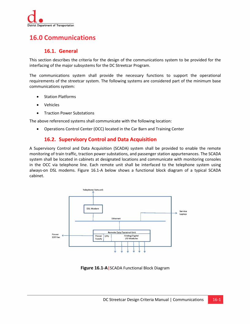
DC Streetcar Design Criteria Manual | Communications 16-1
16.0 Communications
16.1. General
This section describes the criteria for the design of the communications system to be provided for the interfacing of the major subsystems for the DC Streetcar Program.
The communications system shall provide the necessary functions to support the operational requirements of the streetcar system. The following systems are considered part of the minimum base communications system:
• Station Platforms
• Vehicles
• Traction Power Substations
The above referenced systems shall communicate with the following location:
• Operations Control Center (OCC) located in the Car Barn and Training Center
16.2. Supervisory Control and Data Acquisition
A Supervisory Control and Data Acquisition (SCADA) system shall be provided to enable the remote monitoring of train traffic, traction power substations, and passenger station appurtenances. The SCADA system shall be located in cabinets at designated locations and communicate with monitoring consoles in the OCC via telephone line. Each remote unit shall be interfaced to the telephone system using always-on DSL modems. Figure 16.1-A below shows a functional block diagram of a typical SCADA cabinet.
Figure 16.1-A|SCADA Functional Block Diagram
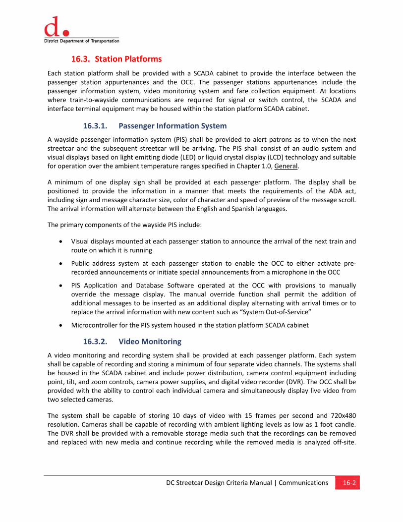
DC Streetcar Design Criteria Manual | Communications 16-2
16.3. Station Platforms
Each station platform shall be provided with a SCADA cabinet to provide the interface between the passenger station appurtenances and the OCC. The passenger stations appurtenances include the passenger information system, video monitoring system and fare collection equipment. At locations where train-to-wayside communications are required for signal or switch control, the SCADA and interface terminal equipment may be housed within the station platform SCADA cabinet.
16.3.1. Passenger Information System
A wayside passenger information system (PIS) shall be provided to alert patrons as to when the next streetcar and the subsequent streetcar will be arriving. The PIS shall consist of an audio system and visual displays based on light emitting diode (LED) or liquid crystal display (LCD) technology and suitable for operation over the ambient temperature ranges specified in Chapter 1.0, General.
A minimum of one display sign shall be provided at each passenger platform. The display shall be positioned to provide the information in a manner that meets the requirements of the ADA act, including sign and message character size, color of character and speed of preview of the message scroll. The arrival information will alternate between the English and Spanish languages.
The primary components of the wayside PIS include:
• Visual displays mounted at each passenger station to announce the arrival of the next train and route on which it is running
• Public address system at each passenger station to enable the OCC to either activate pre-recorded announcements or initiate special announcements from a microphone in the OCC
• PIS Application and Database Software operated at the OCC with provisions to manually override the message display. The manual override function shall permit the addition of additional messages to be inserted as an additional display alternating with arrival times or to replace the arrival information with new content such as “System Out-of-Service”
• Microcontroller for the PIS system housed in the station platform SCADA cabinet
16.3.2. Video Monitoring
A video monitoring and recording system shall be provided at each passenger platform. Each system shall be capable of recording and storing a minimum of four separate video channels. The systems shall be housed in the SCADA cabinet and include power distribution, camera control equipment including point, tilt, and zoom controls, camera power supplies, and digital video recorder (DVR). The OCC shall be provided with the ability to control each individual camera and simultaneously display live video from two selected cameras.
The system shall be capable of storing 10 days of video with 15 frames per second and 720x480 resolution. Cameras shall be capable of recording with ambient lighting levels as low as 1 foot candle. The DVR shall be provided with a removable storage media such that the recordings can be removed and replaced with new media and continue recording while the removed media is analyzed off-site.
DC Streetcar Design Criteria Manual | Communications 16-3
Provisions for copying the recorded media to a laptop computer without altering the original recording shall also be provided.
The number, style (hidden or noticeable) and locations of cameras shall be reviewed and approved by DDOT.
16.3.3. Fare Collection
Each fare collection machine installed on the passenger station platform shall be provided with a status and alarm system for reporting to the OCC through the station platform SCADA system.
The OCC shall be provided with a display for viewing of the status of each machine. The display may be a stand-alone unit or configured to operate on a personal computer.
At a minimum the following indications shall be provided:
• Ticket restocking
• Out-of-change
• Malfunctions according to machine capability
• Security violation
• Service entry for normal maintenance
16.4. Vehicles
16.4.1. Voice Radio System
A two-way radio system between Streetcar personnel and the OCC shall be provided. The voice radio system shall include vehicle born mobile and portable radio sets.
The radios shall be fully compatible with all features operating as part of the District of Columbia’s 800 MHz digitally trunked public safety radio system.
The following minimum channels shall be made available for all DC Streetcar radios:
• Streetcar Vehicle Operations
• Maintenance-of-Way Operations
• Maintenance Facility Operations
• Operations Control Center
• Other channels as determined necessary (Up to a maximum of four)
Specific requirements for talk groups shall be defined as the project progresses.
A voice radio base station shall be provided for the System Supervisor at the OCC. The base station shall be provided with the capability of recording all radio traffic on all channels of the system.

DC Streetcar Design Criteria Manual | Communications 16-4
16.4.2. Automatic Vehicle Location System
An automatic vehicle location (AVL) shall be installed on the vehicle. The system shall be based on GPS location information supplemented by dead reckoning. The vehicles location shall be provided to the OCC either via cellular telephone or data radio communication.
16.5. Traction Power Substations
Each mainline substation shall be provided with a status and alarm system for transmission of substation status to the OCC through a SCADA cabinet installed in the substation.
The OCC shall be provided with a display for viewing of the status of each substation. The display may be a stand-alone unit or configured to operate on a personal computer.
At a minimum the following indications shall be provided:
• AC breaker open
• Feeder breaker 1 open
• Feeder breaker 2 open
• Overtemperature alarm (prior to trip)
• Fire detected
• Intrusion detected
Applicable Standard Drawings:
E-01 Low Voltage Substation Typical Layout and Grounding Plan E-02 Systemwide Electrical - Typical Manhole Installation E-03 Systemwide Electrical - Conduit Installation Details E-04 Systemwide Electrical - Negative Connection To Rail E-05 Train To Wayside Communication - Installation Details
Chapter 17 Fare Collection
Content
17.1. Fare Collection Equipment 17.2. Fare Structure 17.3. Fare Enforcement
DC Streetcar Design Criteria Manual | Fare Collection 17-1
17.0 Fare Collection The fare collection system for the DC Streetcar System shall use a barrier-free, self-service method similar to other Streetcar and Light Rail Systems in the United States. The fare collection system equipment to be selected shall have been proven in transit revenue service.
Fare collection equipment will be located both on-board the vehicle and on station platforms. Additional equipment will be required to collect the monies from vending machines on the station platforms and data from the equipment on-board the vehicles. There will not be a system of station attendants, physical barriers or gates preventing access to the system without prior payment. All fare collection equipment shall be installed to meet the requirements of the Americans with Disabilities Act.
17.1. Fare Collection Equipment
The fare collection equipment shall consist of ticket vending machines on the station platforms and SmartTrip card readers to be installed on the vehicles. The station platform ticket vending machines shall be installed in an illuminated area and monitored by the video monitoring system. Ticket vending machines shall have the capability to vend single-ride tickets. They shall have the capability to accept United States currency and issue change for overpayment of the ticket. Ticket vending machines shall dispense a ticket imprinted with the current date, time, and vending machine code. They may be configured to accept credit and debit cards. The SmartTrip card readers shall function with WMATA’s integrated fare collection system. The readers will be mounted at the vehicle doorways and provide for payment of fare by touching the SmartTrip card to the circular target on the reader.
17.2. Fare Structure
The fare structure and potential integration with the fare systems and structures of the regional transit authorities are undetermined at this time.
17.3. Fare Enforcement
Fare enforcement is assumed to be the responsibility of the operator. DDOT will need to provide the necessary authority via City regulations.
Angel A. PenaProject Manager | Civil EngineerDC Streetcar ProgramProgressive Transportation Services AdministrationDistrict Department of Transportation55 M Street SE, Washington DC 20003www.ddot.dc. ov
Government of District of ColumbiaVincent C. Gray, Mayor
District Department of TransportationTerry Bellamy, Director
Angel A. PenaProject Manager | Civil EngineerDC Streetcar ProgramProgressive Transportation Services AdministrationDistrict Department of Transportation55 M Street SE Suite 500Washington DC 20003www.ddot.dc.gov