janus design suite - janus fire systems · janus design suite is used to design and develop special...
TRANSCRIPT

Author: Matt Ricci Company: Janus Fire Systems Version: 1.0.0.0 Initial Release: 3/5/2009 Revision: E Revision Date: 2/8/2013
Janus Design Suite Flow Calculation Software Manual

DOC 106 Janus Fire Systems 2 Revision E 2/8/2013
Blank
DOC 106 Janus Fire Systems 3 Revision E 2/8/2013
Table of Contents Janus Design Suite ......................................................................................................................... 8 Getting Started ............................................................................................................................... 8 Installation ...................................................................................................................................... 9
System Requirements................................................................................................................ 9 Installation .................................................................................................................................. 9 Uninstall ....................................................................................................................................... 9
Starting the program ................................................................................................................... 10 Registration Verification .............................................................................................................. 11
Time Period Display Bar .......................................................................................................... 13 Register Program / Registration Confirmed ......................................................................... 13 Exit Program ............................................................................................................................. 13
User Registration Form ............................................................................................................... 14 User Registration Form ........................................................................................................... 14
Dialogs ........................................................................................................................................... 15 JDS Main User Interface ............................................................................................................. 16 Ribbon Bar..................................................................................................................................... 17
File Tab ...................................................................................................................................... 18 JDS Tab ..................................................................................................................................... 19 FM-200 Tab ............................................................................................................................... 20
Printing .......................................................................................................................................... 22 Items to Print ............................................................................................................................ 22 Result Printout .......................................................................................................................... 23 File Format to Print .................................................................................................................. 23 Print to File ................................................................................................................................ 23 Print to PDF ............................................................................................................................... 23 Print to CSV File ....................................................................................................................... 23 Preview ...................................................................................................................................... 23 Print Setup ................................................................................................................................ 24 Print / Save to File ................................................................................................................... 24 Close........................................................................................................................................... 24
Agent Requirement Calculator ................................................................................................... 25 Registration Information ............................................................................................................. 26
Changing User Name ............................................................................................................... 26 Modifying Serial Key ................................................................................................................ 26
Custom Pipe Types ...................................................................................................................... 27 Custom Pipe Table ................................................................................................................... 27 Entering A Custom Pipe .......................................................................................................... 28 Editing A Custom Pipe ............................................................................................................. 28 Deleting A Custom Pipe .......................................................................................................... 29
Pipe Table Instructions ............................................................................................................... 30 Send To Tech. Support ............................................................................................................... 31 About Dialog ................................................................................................................................. 32 Toolbar........................................................................................................................................... 33
DOC 106 Janus Fire Systems 4 Revision E 2/8/2013
Icons .......................................................................................................................................... 33 Agency Approvals ......................................................................................................................... 34
Agency Approvals Form .......................................................................................................... 34 FM-200 Design ............................................................................................................................. 35 FM-200 Agent Design Form ........................................................................................................ 36 System Tabs ................................................................................................................................. 37
Navigating Tabs........................................................................................................................ 37 System Constraints Tab .............................................................................................................. 38
System Constraints .................................................................................................................. 38 Project Information .................................................................................................................. 39 Cylinder Information ................................................................................................................ 39 Configuration Variables ........................................................................................................... 40 Customer Information ............................................................................................................. 41
Entering User Specified Cylinders .............................................................................................. 43 Using a Janus Fire Systems Discharge Valve....................................................................... 43 Using a non-Janus Fire Systems Discharge Valve .............................................................. 44
Hazard Characteristics Tab ......................................................................................................... 45 Hazard Characteristics ............................................................................................................. 45 Enclosure Data ......................................................................................................................... 46 Enclosure Volume .................................................................................................................... 46 Area Nozzle List ........................................................................................................................ 47
Flammables Concentration ......................................................................................................... 48 Piping Network Tab ..................................................................................................................... 49
Piping Network ......................................................................................................................... 49 Piping Input Grid ...................................................................................................................... 49 Piping Network Functions ....................................................................................................... 51
Manifold Dead Leg Calculation Wizard ..................................................................................... 52 Notes on Selector Valve Calculation ...................................................................................... 52 Manifold Dead Leg Calculation Wizard Form ....................................................................... 53 Notes on Selector Valve Modeling ......................................................................................... 53
System Design .............................................................................................................................. 55 Hazard Analysis ........................................................................................................................ 55 Agent Requirement .................................................................................................................. 57 Number of Cylinders ................................................................................................................ 58 Cylinder Location ...................................................................................................................... 58 Nozzle Determination .............................................................................................................. 58 Pipe Determination .................................................................................................................. 60
Notes On Pipe Modeling .............................................................................................................. 60 Modeling Section 1 to 2 .......................................................................................................... 60 Modeling New Sections ........................................................................................................... 60 Modeling Nozzles ...................................................................................................................... 61 Notes on Terminal Points ........................................................................................................ 61 Notes on Pipe Routing ............................................................................................................. 61 Notes on Elevation Difference ................................................................................................ 61
DOC 106 Janus Fire Systems 5 Revision E 2/8/2013
Nozzles ........................................................................................................................................... 62 Orientation ................................................................................................................................ 62 Dimensions ................................................................................................................................ 62
Nozzle References ........................................................................................................................ 63 Nozzle Reference...................................................................................................................... 63
Results Tab ................................................................................................................................... 64 Results ....................................................................................................................................... 64 Result Conditions ..................................................................................................................... 64 Piping Results ........................................................................................................................... 65
Nozzle Performance Summary Tab ........................................................................................... 66 Nozzle Performance Summary ............................................................................................... 66
Hazard Concentration Summary Tab ........................................................................................ 67 Hazard Concentration Summary ............................................................................................ 67
Venting Tab ................................................................................................................................... 68 Venting ...................................................................................................................................... 68
NFPA Requirements for Venting ................................................................................................ 69 Error Messages / Design Notes Tab .......................................................................................... 70
Error Messages / Design Notes .............................................................................................. 70 Error / Design Message Help Bubble .................................................................................... 70
Minimum Flow Rates ................................................................................................................... 71 Notes on Calculation .................................................................................................................... 72
Error Checking .......................................................................................................................... 72 Pre-Calculation Error Messages ................................................................................................. 73 Troubleshooting Calculation Errors ........................................................................................... 76
Design Notes ............................................................................................................................. 78 Flow Theory .................................................................................................................................. 79
Pipeline Density ........................................................................................................................ 79 Friction Factor ........................................................................................................................... 81 Mechanical Effects ................................................................................................................... 83 Elevation Change ..................................................................................................................... 85 Transient Effects ...................................................................................................................... 85
FM-200 Calculation Example ...................................................................................................... 86 Example Plan View ....................................................................................................................... 86 Example Isometric View .............................................................................................................. 87 Definitions ..................................................................................................................................... 95 Copyright ....................................................................................................................................... 96
DOC 106 Janus Fire Systems 6 Revision E 2/8/2013
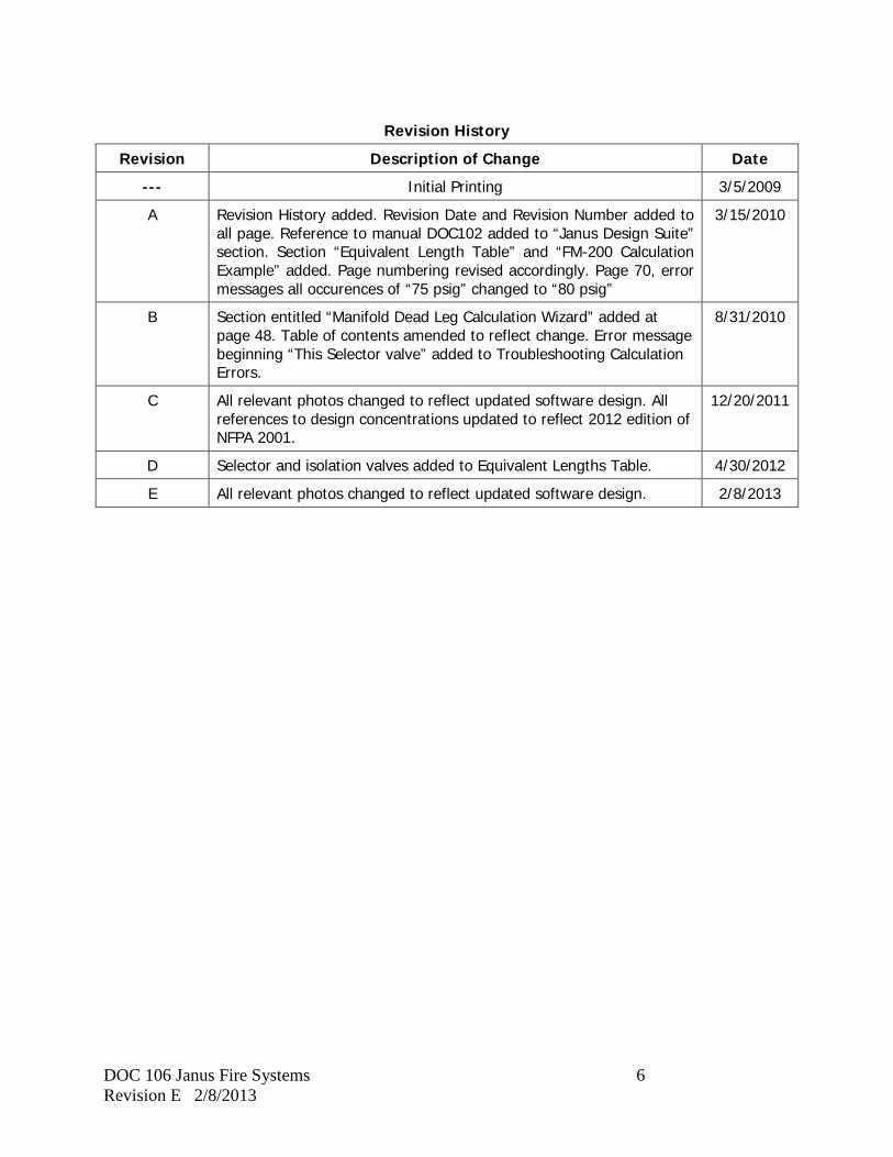
Revision History
Revision Description of Change Date
--- Initial Printing 3/5/2009
A Revision History added. Revision Date and Revision Number added to all page. Reference to manual DOC102 added to “Janus Design Suite” section. Section “Equivalent Length Table” and “FM-200 Calculation Example” added. Page numbering revised accordingly. Page 70, error messages all occurences of “75 psig” changed to “80 psig”
3/15/2010
B Section entitled “Manifold Dead Leg Calculation Wizard” added at page 48. Table of contents amended to reflect change. Error message beginning “This Selector valve” added to Troubleshooting Calculation Errors.
8/31/2010
C All relevant photos changed to reflect updated software design. All references to design concentrations updated to reflect 2012 edition of NFPA 2001.
12/20/2011
D Selector and isolation valves added to Equivalent Lengths Table. 4/30/2012
E All relevant photos changed to reflect updated software design. 2/8/2013

DOC 106 Janus Fire Systems 7 Revision E 2/8/2013
Blank
DOC 106 Janus Fire Systems 8 Revision E 2/8/2013
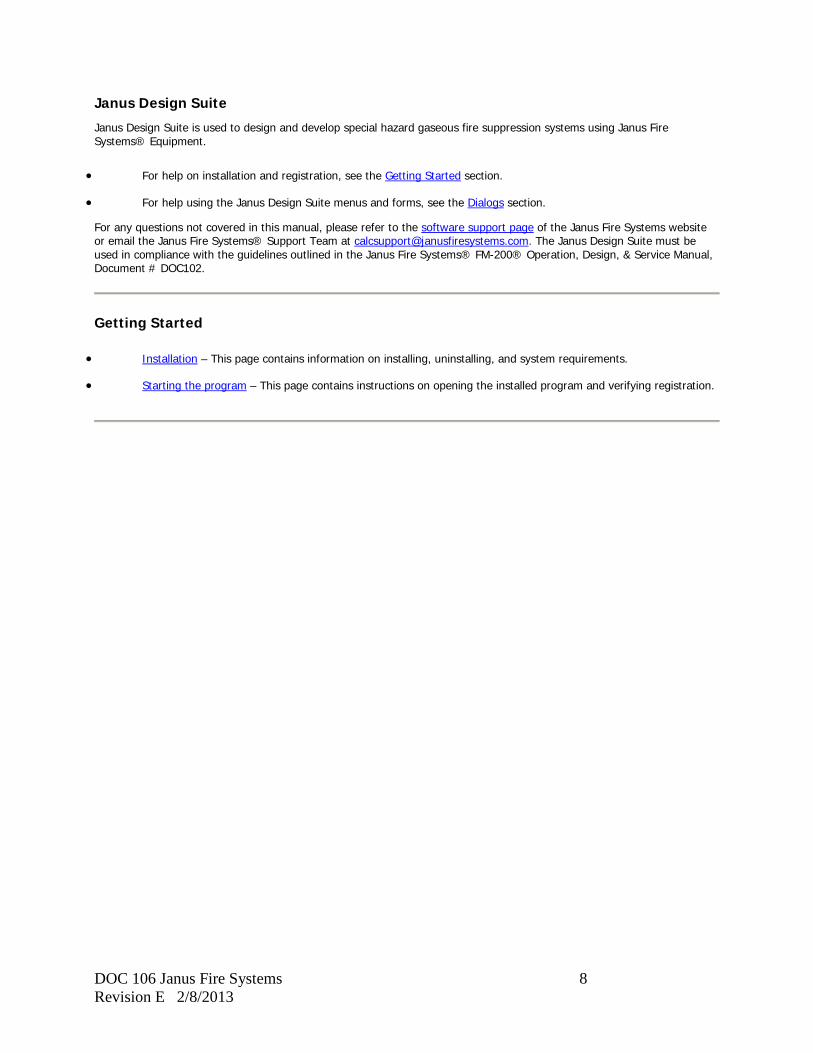
Janus Design Suite
Janus Design Suite is used to design and develop special hazard gaseous fire suppression systems using Janus Fire Systems® Equipment.
• For help on installation and registration, see the Getting Started section.
• For help using the Janus Design Suite menus and forms, see the Dialogs section.
For any questions not covered in this manual, please refer to the software support page of the Janus Fire Systems website or email the Janus Fire Systems® Support Team at [email protected]. The Janus Design Suite must be used in compliance with the guidelines outlined in the Janus Fire Systems® FM-200® Operation, Design, & Service Manual, Document # DOC102.
Getting Started
• Installation – This page contains information on installing, uninstalling, and system requirements.
• Starting the program – This page contains instructions on opening the installed program and verifying registration.

DOC 106 Janus Fire Systems 9 Revision E 2/8/2013
Installation
System Requirements
• Pentium 3 processor minimum, 256 MB Ram
• Windows XP/Vista/7/8 (both 32-bit and 64-bit)
• Microsoft.Net Framework v3.5 and v4.0 (included in setup file)
• SQL Server Express 2008 R2 SP1 (included in setup file)
• Crystal Reports 2010 (included in setup file)
• Windows Power Shell v1.0 (included in setup file)
Installation
To Install Janus Design Suite:
1. Double-click the Janus_JDS.exe file.
2. The setup program will launch.
3. Follow the onscreen instructions to complete installation.
Uninstall
To Uninstall Janus Design Suite:
1. Click the [Start] button.
2. Select Settings > Control Panel.
3. Double-click Add/Remove Programs.
4. Click Change or Remove Programs.
5. Select Janus Design Suite from the list of programs.
6. Click the [Remove...] button to uninstall Janus Design Suite.

DOC 106 Janus Fire Systems 10 Revision E 2/8/2013
Starting the program
To start Janus Design Suite, click on the Janus Design Suite icon found in the Start menu under Programs / Janus Design Suite or else double-click the Janus Design Suite icon located on the desktop.
Once the program is opened, the program load screen will appear.
The progress bar as the bottom of the screen shows the time remaining for the Janus Design Suite to finish loading. Once loading is complete, the Registration Verification screen will appear.
NOTE: The Janus Design Suite must be registered before it can be used. The version number displayed on the program load screen may not match the picture shown above.
DOC 106 Janus Fire Systems 11 Revision E 2/8/2013
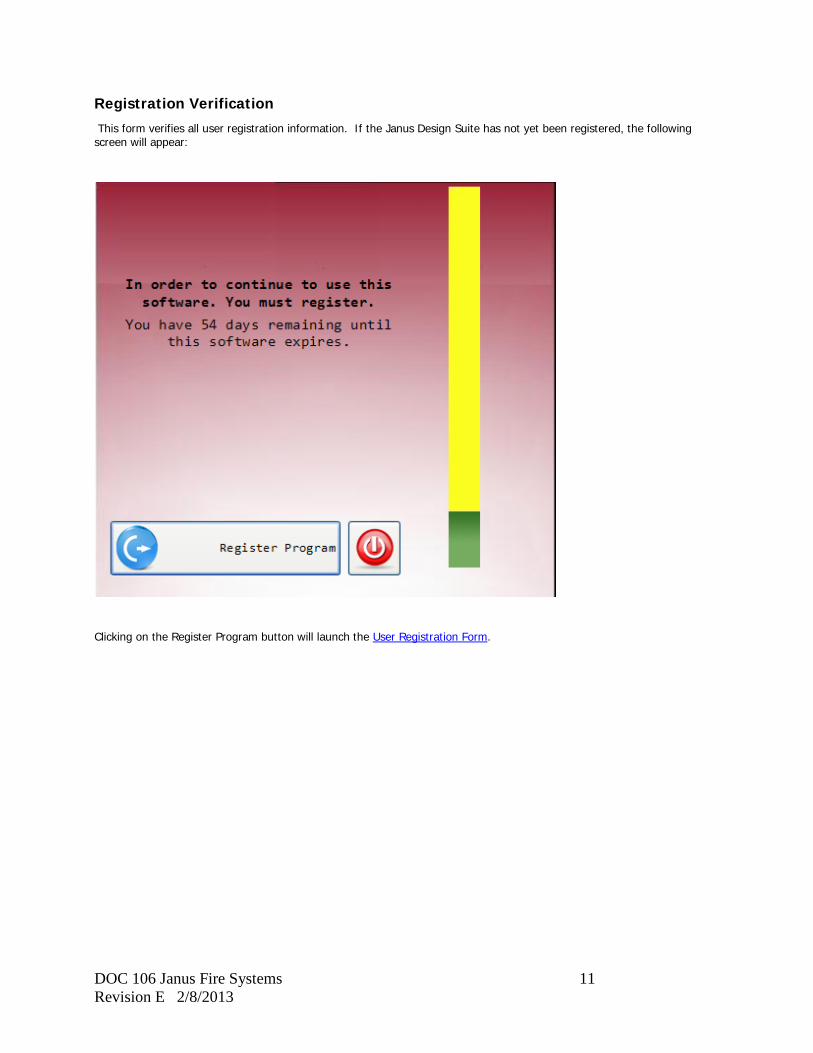
Registration Verification
This form verifies all user registration information. If the Janus Design Suite has not yet been registered, the following screen will appear:
Clicking on the Register Program button will launch the User Registration Form.
DOC 106 Janus Fire Systems 12 Revision E 2/8/2013
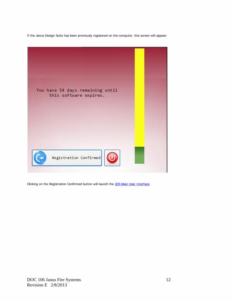
If the Janus Design Suite has been previously registered on the computer, this screen will appear:
Clicking on the Registration Confirmed button will launch the JDS Main User Interface.

DOC 106 Janus Fire Systems 13 Revision E 2/8/2013
Time Period Display Bar
The bar at the center of the Registration Verification screen provides a graphical representation of the number of days left before the software expires. Software expires January 1 of the year following the version release date.
Register Program / Registration Confirmed
This button is located in the lower left corner of the Registration Verification Form. If your copy of the Janus Design Suite has not yet been registered, the button will display "Register Program". Clicking this will open up the User Registration Form. After registration has been completed, the button will display "Registration Confirmed". Clicking this will launch the JDS Main User Interface.
Exit Program
Clicking this button will close the application.
DOC 106 Janus Fire Systems 14 Revision E 2/8/2013
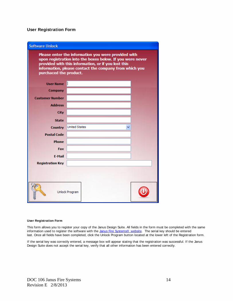
User Registration Form
User Registration Form
This form allows you to register your copy of the Janus Design Suite. All fields in the form must be completed with the same information used to register the software with the Janus Fire Systems® website. The serial key should be entered last. Once all fields have been completed, click the Unlock Program button located at the lower left of the Registration form.
If the serial key was correctly entered, a message box will appear stating that the registration was successful. If the Janus Design Suite does not accept the serial key, verify that all other information has been entered correctly.
DOC 106 Janus Fire Systems 15 Revision E 2/8/2013
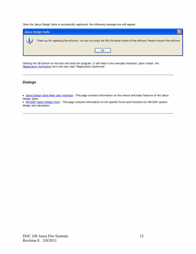
Once the Janus Design Suite is successfully registered, the following message box will appear:
Clicking the OK button on this box will close the program. It will need to be manually restarted. Upon restart, the Registration Verification form will now read "Registration Confirmed".
Dialogs
• Janus Design Suite Main User Interface - This page contains information on the menus and basic features of the Janus Design Suite. • FM-200® Agent Design Form - This page contains information on the specific forms and functions for FM-200® system design and calculation.
DOC 106 Janus Fire Systems 16 Revision E 2/8/2013
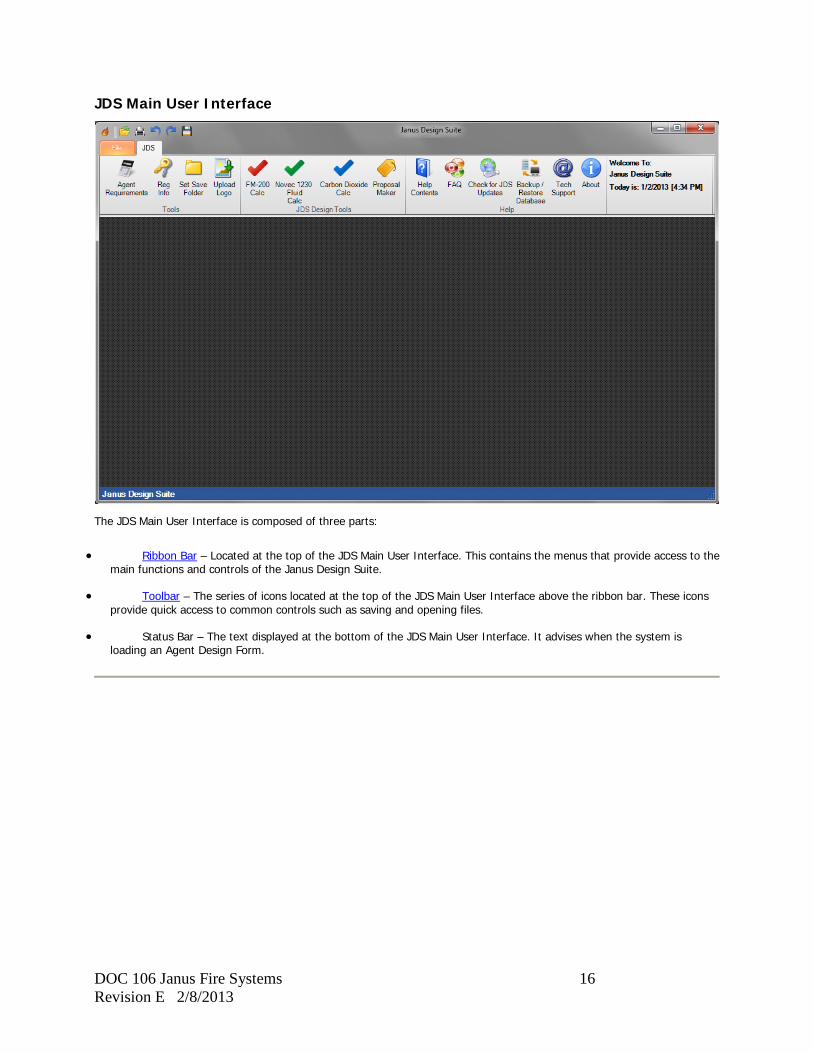
JDS Main User Interface
The JDS Main User Interface is composed of three parts:
• Ribbon Bar – Located at the top of the JDS Main User Interface. This contains the menus that provide access to the main functions and controls of the Janus Design Suite.
• Toolbar – The series of icons located at the top of the JDS Main User Interface above the ribbon bar. These icons provide quick access to common controls such as saving and opening files.
• Status Bar – The text displayed at the bottom of the JDS Main User Interface. It advises when the system is loading an Agent Design Form.
DOC 106 Janus Fire Systems 17 Revision E 2/8/2013
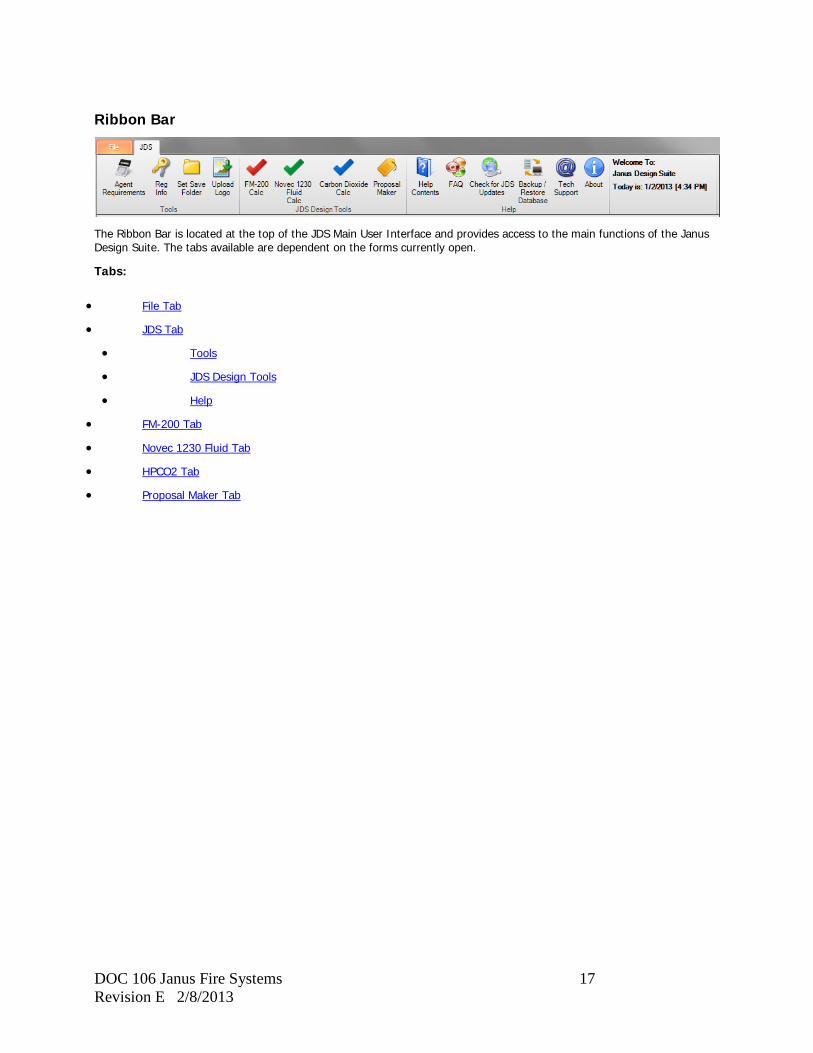
Ribbon Bar
The Ribbon Bar is located at the top of the JDS Main User Interface and provides access to the main functions of the Janus Design Suite. The tabs available are dependent on the forms currently open.
Tabs:
• File Tab
• JDS Tab
• Tools
• JDS Design Tools
• Help
• FM-200 Tab
• Novec 1230 Fluid Tab
• HPCO2 Tab
• Proposal Maker Tab
DOC 106 Janus Fire Systems 18 Revision E 2/8/2013
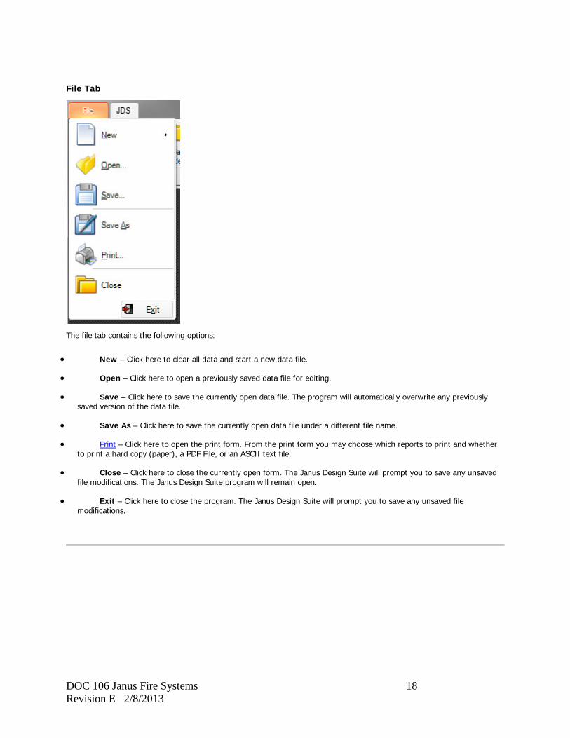
File Tab
The file tab contains the following options:
• New – Click here to clear all data and start a new data file.
• Open – Click here to open a previously saved data file for editing.
• Save – Click here to save the currently open data file. The program will automatically overwrite any previously saved version of the data file.
• Save As – Click here to save the currently open data file under a different file name.
• Print – Click here to open the print form. From the print form you may choose which reports to print and whether to print a hard copy (paper), a PDF File, or an ASCII text file.
• Close – Click here to close the currently open form. The Janus Design Suite will prompt you to save any unsaved file modifications. The Janus Design Suite program will remain open.
• Exit – Click here to close the program. The Janus Design Suite will prompt you to save any unsaved file modifications.
DOC 106 Janus Fire Systems 19 Revision E 2/8/2013
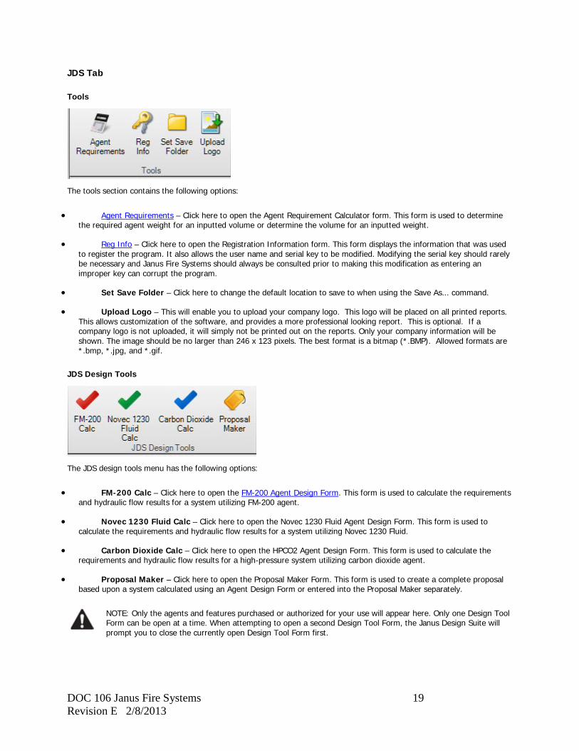
JDS Tab
Tools
The tools section contains the following options:
• Agent Requirements – Click here to open the Agent Requirement Calculator form. This form is used to determine the required agent weight for an inputted volume or determine the volume for an inputted weight.
• Reg Info – Click here to open the Registration Information form. This form displays the information that was used to register the program. It also allows the user name and serial key to be modified. Modifying the serial key should rarely be necessary and Janus Fire Systems should always be consulted prior to making this modification as entering an improper key can corrupt the program.
• Set Save Folder – Click here to change the default location to save to when using the Save As... command.
• Upload Logo – This will enable you to upload your company logo. This logo will be placed on all printed reports. This allows customization of the software, and provides a more professional looking report. This is optional. If a company logo is not uploaded, it will simply not be printed out on the reports. Only your company information will be shown. The image should be no larger than 246 x 123 pixels. The best format is a bitmap (*.BMP). Allowed formats are *.bmp, *.jpg, and *.gif.
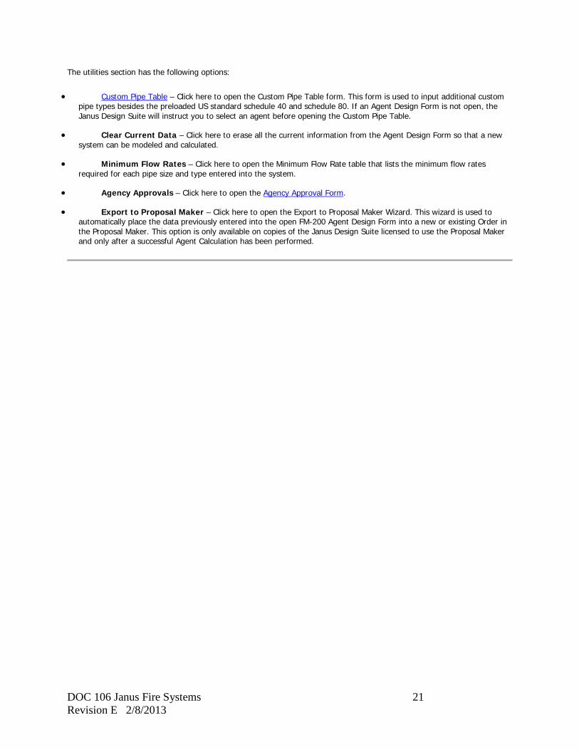
JDS Design Tools
The JDS design tools menu has the following options:
• FM-200 Calc – Click here to open the FM-200 Agent Design Form. This form is used to calculate the requirements and hydraulic flow results for a system utilizing FM-200 agent.
• Novec 1230 Fluid Calc – Click here to open the Novec 1230 Fluid Agent Design Form. This form is used to calculate the requirements and hydraulic flow results for a system utilizing Novec 1230 Fluid.
• Carbon Dioxide Calc – Click here to open the HPCO2 Agent Design Form. This form is used to calculate the requirements and hydraulic flow results for a high-pressure system utilizing carbon dioxide agent.
• Proposal Maker – Click here to open the Proposal Maker Form. This form is used to create a complete proposal based upon a system calculated using an Agent Design Form or entered into the Proposal Maker separately.
NOTE: Only the agents and features purchased or authorized for your use will appear here. Only one Design Tool Form can be open at a time. When attempting to open a second Design Tool Form, the Janus Design Suite will prompt you to close the currently open Design Tool Form first.

DOC 106 Janus Fire Systems 20 Revision E 2/8/2013
Help
The help section contains the following options:
• Help Contents – Click here to open this help file and display the help file contents.
• FAQ – Click here to open the software support page at the Janus Fire Systems website. In some cases, this FAQ page will be more up-to-date than this help file. An active Internet connection is required to use this feature.
• Check For JDS Updates – Click here to check for updates to the Janus Design Suite. This check should be performed once a month. An active Internet connection is required to use this feature. If updates are found, you will be prompted to download them. After the download is complete, the software will need to be restarted. A message box will prompt you to save data before restart. Previous info entered into the Janus Design Suite database will not be lost following this update.
• Backup / Restore Database – Click here to open the Backup & Restore Database Wizard. This wizard is used to save a backup copy of the Janus Design Suite database or to restore the current Janus Design Suite database to a previously saved copy.
• Tech. Support – Click here to export the currently open data file and send it to the Janus Fire Systems® Support Team. This feature is only available when an Agent Design Form has been opened. An active Internet connection is required to send the data file.
• About – Clicking here will open the About Dialog box. This provides the current operating version of the Janus Design Suite, as well as a record of updates made to the software.
FM-200 Tab
This tab only appears when the FM-200 Agent Design Form is open.
The edit section has the following options:
• Paste – Click here to place the data stored in the clipboard into the selected location.
• Cut – Click here to remove the highlighted data and store it in the clipboard for later use.
• Copy – Click here to copy the highlighted data and store it in the clipboard for later use.
• Select All – Click here to highlight all the data contained in the piping grid. This option is only available on the Piping Network Tab of the Agent Design Form.
• Select Row – Click here to highlight all the data contained in the selected row of the piping grid. This option is only available on the Piping Network Tab of the Agent Design Form.
DOC 106 Janus Fire Systems 21 Revision E 2/8/2013
The utilities section has the following options:
• Custom Pipe Table – Click here to open the Custom Pipe Table form. This form is used to input additional custom pipe types besides the preloaded US standard schedule 40 and schedule 80. If an Agent Design Form is not open, the Janus Design Suite will instruct you to select an agent before opening the Custom Pipe Table.
• Clear Current Data – Click here to erase all the current information from the Agent Design Form so that a new system can be modeled and calculated.
• Minimum Flow Rates – Click here to open the Minimum Flow Rate table that lists the minimum flow rates required for each pipe size and type entered into the system.
• Agency Approvals – Click here to open the Agency Approval Form.
• Export to Proposal Maker – Click here to open the Export to Proposal Maker Wizard. This wizard is used to automatically place the data previously entered into the open FM-200 Agent Design Form into a new or existing Order in the Proposal Maker. This option is only available on copies of the Janus Design Suite licensed to use the Proposal Maker and only after a successful Agent Calculation has been performed.
DOC 106 Janus Fire Systems 22 Revision E 2/8/2013
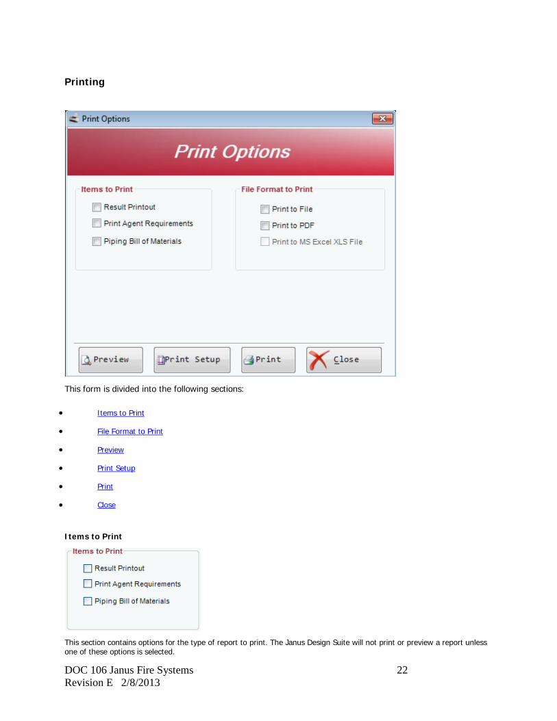
Printing
This form is divided into the following sections:
• Items to Print
• File Format to Print
• Preview
• Print Setup
• Close
Items to Print
This section contains options for the type of report to print. The Janus Design Suite will not print or preview a report unless one of these options is selected.
DOC 106 Janus Fire Systems 23 Revision E 2/8/2013
Result Printout
Check this box to print a report of all Data Input as well as any Calculation Results.
Print Agent Requirements
Check this box to print out a detailed Agent Requirement Calculation for each enclosure listed in the Hazard Characteristics Tab.
Piping Bill of Materials
Check this box to print out a report of all calculated pipe sizes, elbows, tees, and nozzles.
NOTE: This is NOT intended as a buy list. All quantities should be field verified prior to ordering.
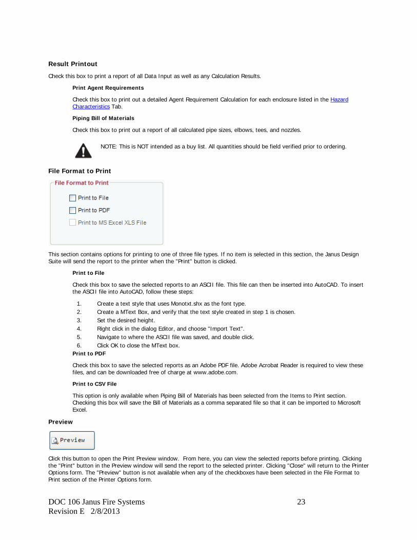
File Format to Print
This section contains options for printing to one of three file types. If no item is selected in this section, the Janus Design Suite will send the report to the printer when the "Print" button is clicked.
Print to File
Check this box to save the selected reports to an ASCII file. This file can then be inserted into AutoCAD. To insert the ASCII file into AutoCAD, follow these steps:
1. Create a text style that uses Monotxt.shx as the font type. 2. Create a MText Box, and verify that the text style created in step 1 is chosen. 3. Set the desired height. 4. Right click in the dialog Editor, and choose "Import Text". 5. Navigate to where the ASCII file was saved, and double click. 6. Click OK to close the MText box.
Print to PDF
Check this box to save the selected reports as an Adobe PDF file. Adobe Acrobat Reader is required to view these files, and can be downloaded free of charge at www.adobe.com.
Print to CSV File
This option is only available when Piping Bill of Materials has been selected from the Items to Print section. Checking this box will save the Bill of Materials as a comma separated file so that it can be imported to Microsoft Excel.
Preview
Click this button to open the Print Preview window. From here, you can view the selected reports before printing. Clicking the "Print" button in the Preview window will send the report to the selected printer. Clicking "Close" will return to the Printer Options form. The "Preview" button is not available when any of the checkboxes have been selected in the File Format to Print section of the Printer Options form.
DOC 106 Janus Fire Systems 24 Revision E 2/8/2013
Print Setup
Click this button to open the print setup window. From this window you may select the device to print to or change the print properties of the selected device.
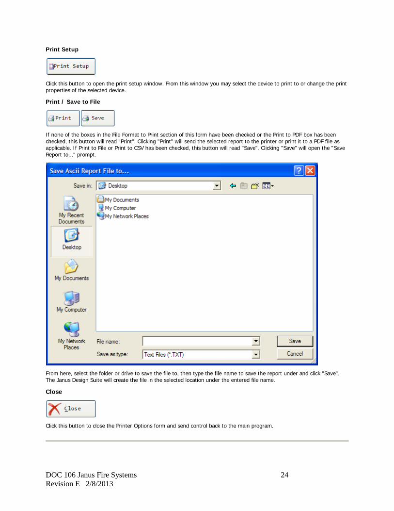
Print / Save to File
If none of the boxes in the File Format to Print section of this form have been checked or the Print to PDF box has been checked, this button will read "Print". Clicking "Print" will send the selected report to the printer or print it to a PDF file as applicable. If Print to File or Print to CSV has been checked, this button will read "Save". Clicking "Save" will open the "Save Report to..." prompt.
From here, select the folder or drive to save the file to, then type the file name to save the report under and click "Save". The Janus Design Suite will create the file in the selected location under the entered file name.
Close
Click this button to close the Printer Options form and send control back to the main program.
DOC 106 Janus Fire Systems 25 Revision E 2/8/2013
Agent Requirement Calculator
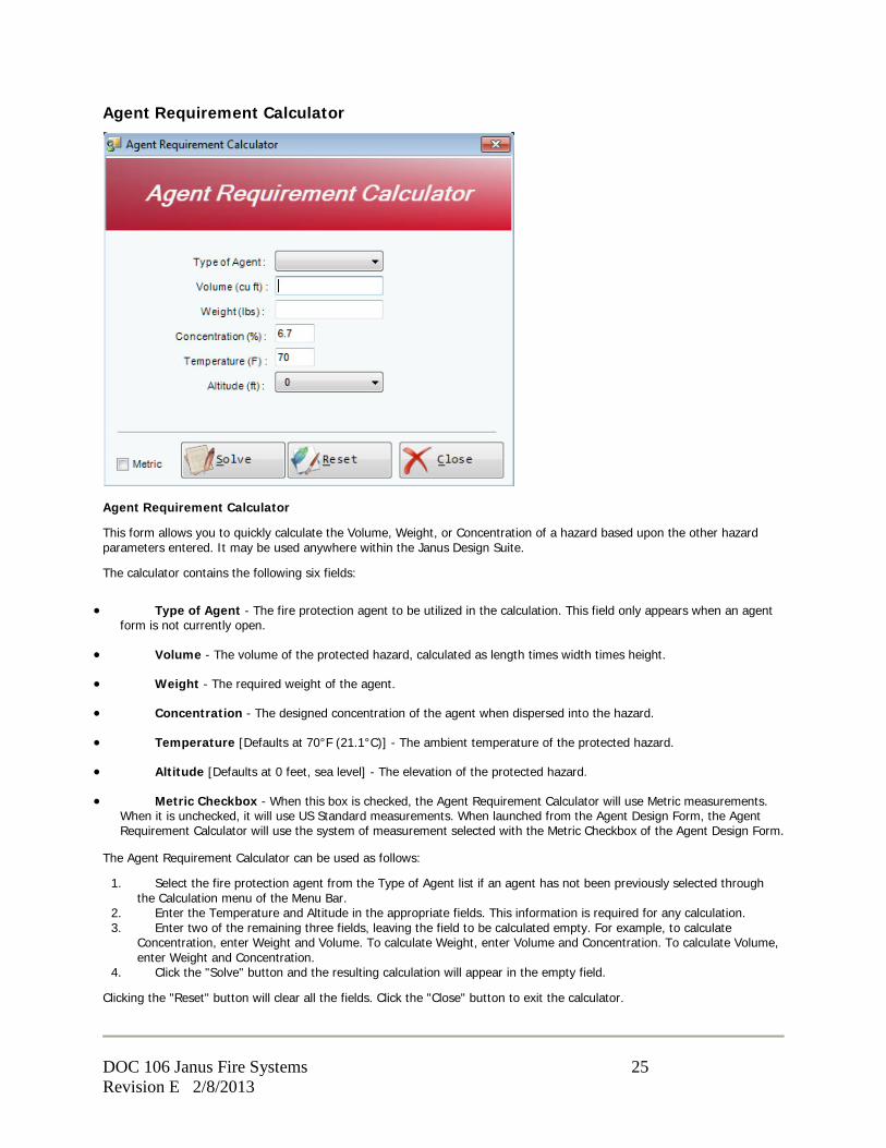
Agent Requirement Calculator
This form allows you to quickly calculate the Volume, Weight, or Concentration of a hazard based upon the other hazard parameters entered. It may be used anywhere within the Janus Design Suite.
The calculator contains the following six fields:
• Type of Agent - The fire protection agent to be utilized in the calculation. This field only appears when an agent form is not currently open.
• Volume - The volume of the protected hazard, calculated as length times width times height.
• Weight - The required weight of the agent.
• Concentration - The designed concentration of the agent when dispersed into the hazard.
• Temperature [Defaults at 70°F (21.1°C)] - The ambient temperature of the protected hazard.
• Altitude [Defaults at 0 feet, sea level] - The elevation of the protected hazard.
• Metric Checkbox - When this box is checked, the Agent Requirement Calculator will use Metric measurements. When it is unchecked, it will use US Standard measurements. When launched from the Agent Design Form, the Agent Requirement Calculator will use the system of measurement selected with the Metric Checkbox of the Agent Design Form.
The Agent Requirement Calculator can be used as follows:
1. Select the fire protection agent from the Type of Agent list if an agent has not been previously selected through the Calculation menu of the Menu Bar.
2. Enter the Temperature and Altitude in the appropriate fields. This information is required for any calculation. 3. Enter two of the remaining three fields, leaving the field to be calculated empty. For example, to calculate
Concentration, enter Weight and Volume. To calculate Weight, enter Volume and Concentration. To calculate Volume, enter Weight and Concentration.
4. Click the "Solve" button and the resulting calculation will appear in the empty field.
Clicking the "Reset" button will clear all the fields. Click the "Close" button to exit the calculator.
DOC 106 Janus Fire Systems 26 Revision E 2/8/2013
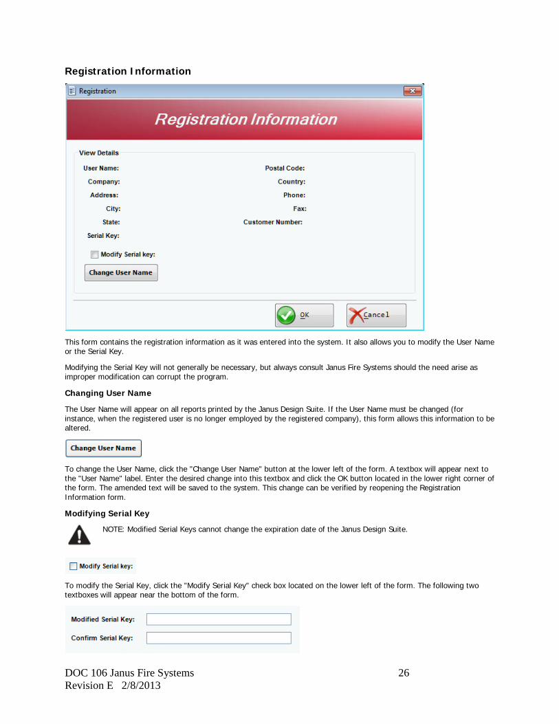
Registration Information
This form contains the registration information as it was entered into the system. It also allows you to modify the User Name or the Serial Key.
Modifying the Serial Key will not generally be necessary, but always consult Janus Fire Systems should the need arise as improper modification can corrupt the program.
Changing User Name
The User Name will appear on all reports printed by the Janus Design Suite. If the User Name must be changed (for instance, when the registered user is no longer employed by the registered company), this form allows this information to be altered.
To change the User Name, click the "Change User Name" button at the lower left of the form. A textbox will appear next to the "User Name" label. Enter the desired change into this textbox and click the OK button located in the lower right corner of the form. The amended text will be saved to the system. This change can be verified by reopening the Registration Information form.
Modifying Serial Key
NOTE: Modified Serial Keys cannot change the expiration date of the Janus Design Suite.
To modify the Serial Key, click the "Modify Serial Key" check box located on the lower left of the form. The following two textboxes will appear near the bottom of the form.

DOC 106 Janus Fire Systems 27 Revision E 2/8/2013
Enter the Modified Serial Key as provided by Janus Fire Systems into both textboxes and click the OK button located in the lower right corner of the form. If the Key entered in the first textbox should not match the second textbox, the Janus Design Suite will prompt you to re-enter the Serial Key. Otherwise, the new Key will be saved to the system.
NOTE: Entering an invalid Serial Key can corrupt the program.
Custom Pipe Types
Custom Pipe Table
The Custom Pipe Table allows users to input custom pipe types. In several different countries, standard US pipe schedules are not available. This form enables you to add the pipes available in your country to the pipes available to the math module. The following standard US pipe schedules come preloaded in the software and cannot be modified or deleted:
DOC 106 Janus Fire Systems 28 Revision E 2/8/2013
• SCH 40 - Schedule 40 pipe with threaded fittings
• SCH 80 - Schedule 80 pipe with threaded fittings
• WLD 40 - Schedule 40 pipe with welded fittings
• WLD 80 - Schedule 80 pipe with welded fittings
• GRV 40 - Schedule 40 pipe with grooved fittings (Not an option for High Pressure CO2)
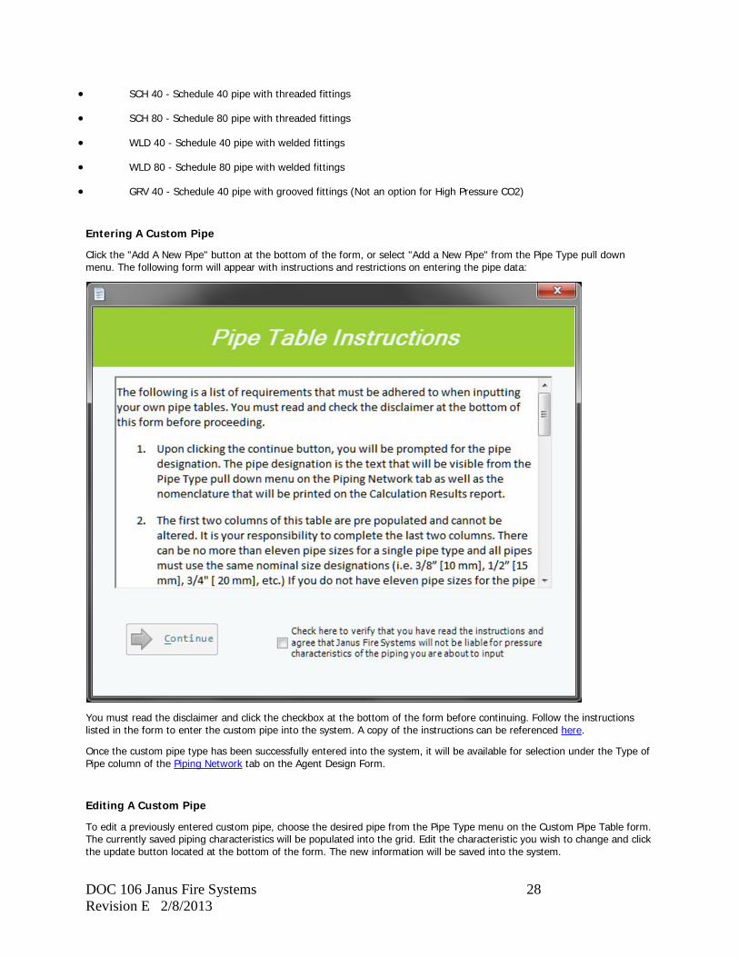
Entering A Custom Pipe
Click the "Add A New Pipe" button at the bottom of the form, or select "Add a New Pipe" from the Pipe Type pull down menu. The following form will appear with instructions and restrictions on entering the pipe data:
You must read the disclaimer and click the checkbox at the bottom of the form before continuing. Follow the instructions listed in the form to enter the custom pipe into the system. A copy of the instructions can be referenced here.
Once the custom pipe type has been successfully entered into the system, it will be available for selection under the Type of Pipe column of the Piping Network tab on the Agent Design Form.
Editing A Custom Pipe
To edit a previously entered custom pipe, choose the desired pipe from the Pipe Type menu on the Custom Pipe Table form. The currently saved piping characteristics will be populated into the grid. Edit the characteristic you wish to change and click the update button located at the bottom of the form. The new information will be saved into the system.

DOC 106 Janus Fire Systems 29 Revision E 2/8/2013
NOTE: Any changes made will overwrite the previous information for that pipe type.
Deleting A Custom Pipe
To delete a previously entered custom pipe, choose the unwanted pipe from the Pipe Type menu on the Custom Pipe Table form. The currently saved piping characteristics will be populated into the grid. Click the delete button located at the bottom of the form. You will be prompted to confirm deletion of the record. Clicking "yes" will permanently remove that pipe type from the system software.
DOC 106 Janus Fire Systems 30 Revision E 2/8/2013
Pipe Table Instructions
The following is a list of requirements that must be adhered to when inputting your own pipe tables. You must read and check the disclaimer at the bottom of this form before proceeding.
1. Upon clicking the continue button, you will be prompted for the pipe designation. The pipe designation is the text that will be visible from the Pipe Type pull down menu on the Piping Network tab as well as the nomenclature that will be printed on the Calculation Results report.
2. The first two columns of this table are pre populated and cannot be altered. It is your responsibility to complete the last two columns. There can be no more than eleven pipe sizes for a single pipe type and all pipes must use the same nominal size designations (i.e. 3/8” [10 mm], 1/2” [15 mm], 3/4" [ 20 mm], etc.) If you do not have eleven pipe sizes for the pipe you are entering, leave the balance of the rows blank. For instance, if the entered pipe does not have a 3/8” [10 mm] size, but has a 1/2” [15 mm], then leave the 3/8” [10 mm] size row blank. If the largest nominal pipe size for the entered pipe is 2” [50 mm], then leave the 2-1/2” [65 mm], 3” [80 mm], 4” [100 mm] and 6” [150 mm] lines blank.
3. For each nominal size, enter the Pipe ID and Pipe Weight. Make certain the information entered for these two fields is as accurate as possible. The results of the calculation program will only be as accurate as the information entered for that pipe. The following is a description of the information required.
a. Pipe ID (Pipe Inside Diameter). If Pipe ID is not known, it can be computed by multiplying the wall thickness by two and subtracting this value from the Pipe OD (Pipe Outside Diameter).
b. Pipe Weight (Weight per unit). For US Standard units, this is measured in lbs/ft; for metric units, this is kg/m.
4. Select the joint type for the entered pipe from the Pipe Joint Type group box. Each pipe designation must have the same joint type for all entered sizes. If threaded is chosen, then all pipes entered under that pipe designation will use threaded fittings. To then enter a pipe with grooved fittings (for example), a second custom pipe must be created.
5. When all necessary information has been entered, click the Save button located at the bottom of the form. The program will perform some integrity checks prior to saving the pipe information to the database.
NOTE: The program only uses US Standard values when computing. All metric values entered will be converted to US Standard prior to computation.
JANUS FIRE SYSTEMS ASSUMES NO LIABILITY FOR THE PRESSURE RATING OF THE PIPES BEING ENTERED. ALL PIPES ENTERED ARE REQUIRED TO COMPLY WITH NFPA
2001 - STANDARD ON CLEAN AGENT FIRE EXTINGUISHING SYSTEMS, LATEST EDITION.
DOC 106 Janus Fire Systems 31 Revision E 2/8/2013
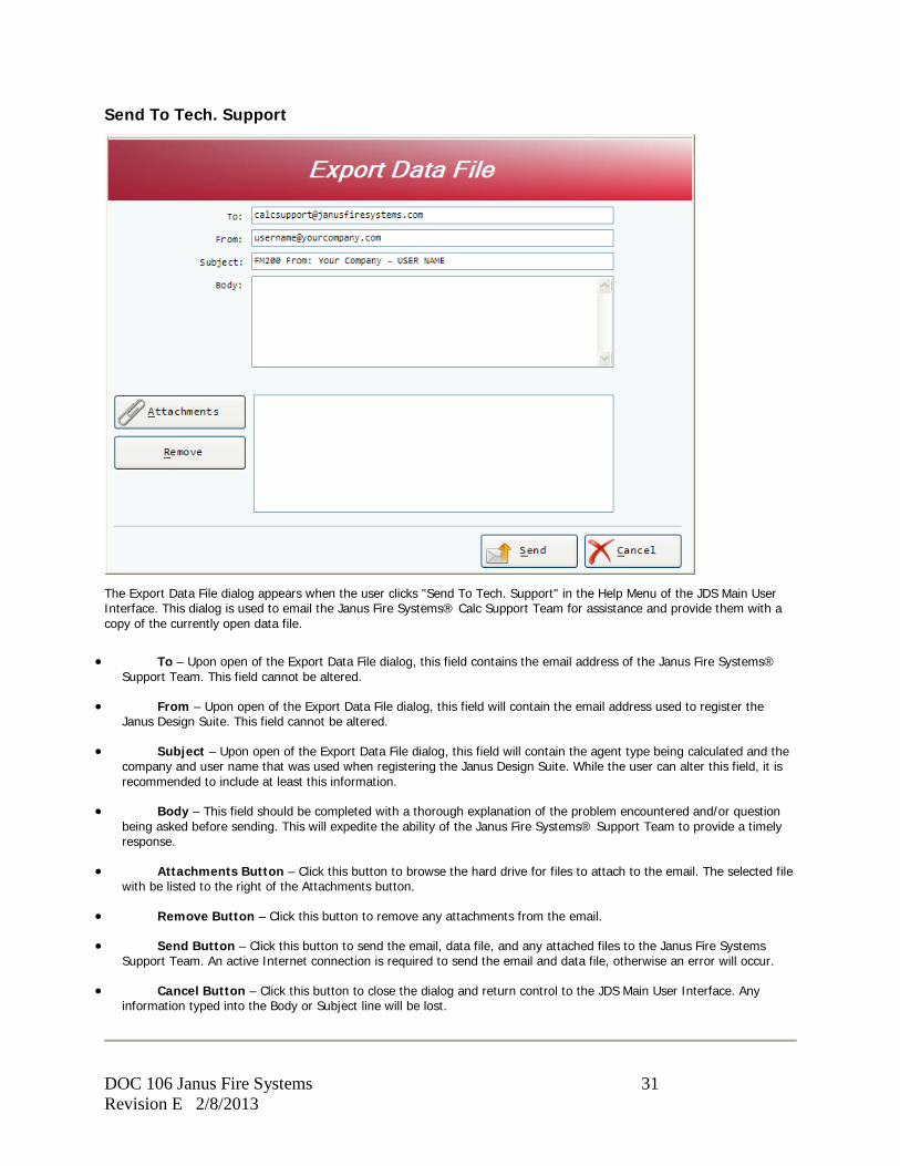
Send To Tech. Support
The Export Data File dialog appears when the user clicks "Send To Tech. Support" in the Help Menu of the JDS Main User Interface. This dialog is used to email the Janus Fire Systems® Calc Support Team for assistance and provide them with a copy of the currently open data file.
• To – Upon open of the Export Data File dialog, this field contains the email address of the Janus Fire Systems® Support Team. This field cannot be altered.
• From – Upon open of the Export Data File dialog, this field will contain the email address used to register the Janus Design Suite. This field cannot be altered.
• Subject – Upon open of the Export Data File dialog, this field will contain the agent type being calculated and the company and user name that was used when registering the Janus Design Suite. While the user can alter this field, it is recommended to include at least this information.
• Body – This field should be completed with a thorough explanation of the problem encountered and/or question being asked before sending. This will expedite the ability of the Janus Fire Systems® Support Team to provide a timely response.
• Attachments Button – Click this button to browse the hard drive for files to attach to the email. The selected file with be listed to the right of the Attachments button.
• Remove Button – Click this button to remove any attachments from the email.
• Send Button – Click this button to send the email, data file, and any attached files to the Janus Fire Systems Support Team. An active Internet connection is required to send the email and data file, otherwise an error will occur.
• Cancel Button – Click this button to close the dialog and return control to the JDS Main User Interface. Any information typed into the Body or Subject line will be lost.
DOC 106 Janus Fire Systems 32 Revision E 2/8/2013
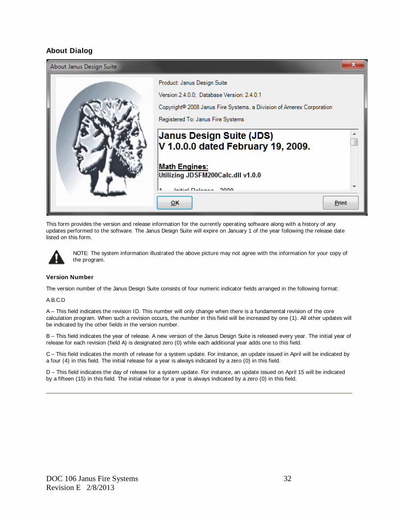
About Dialog
This form provides the version and release information for the currently operating software along with a history of any updates performed to the software. The Janus Design Suite will expire on January 1 of the year following the release date listed on this form.
NOTE: The system information illustrated the above picture may not agree with the information for your copy of the program.
Version Number
The version number of the Janus Design Suite consists of four numeric indicator fields arranged in the following format:
A.B.C.D
A – This field indicates the revision ID. This number will only change when there is a fundamental revision of the core calculation program. When such a revision occurs, the number in this field will be increased by one (1). All other updates will be indicated by the other fields in the version number.
B – This field indicates the year of release. A new version of the Janus Design Suite is released every year. The initial year of release for each revision (field A) is designated zero (0) while each additional year adds one to this field.
C – This field indicates the month of release for a system update. For instance, an update issued in April will be indicated by a four (4) in this field. The initial release for a year is always indicated by a zero (0) in this field.
D – This field indicates the day of release for a system update. For instance, an update issued on April 15 will be indicated by a fifteen (15) in this field. The initial release for a year is always indicated by a zero (0) in this field.
DOC 106 Janus Fire Systems 33 Revision E 2/8/2013
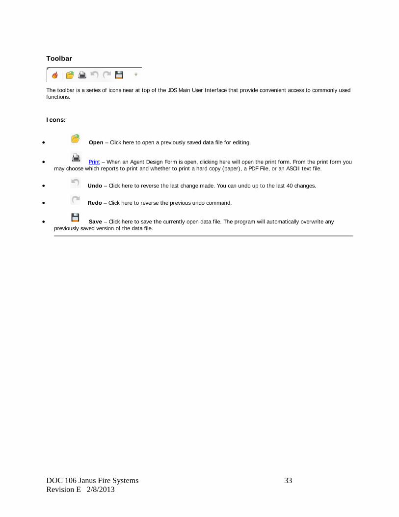
Toolbar
The toolbar is a series of icons near at top of the JDS Main User Interface that provide convenient access to commonly used functions.
Icons:
• Open – Click here to open a previously saved data file for editing.
• Print – When an Agent Design Form is open, clicking here will open the print form. From the print form you may choose which reports to print and whether to print a hard copy (paper), a PDF File, or an ASCII text file.
• Undo – Click here to reverse the last change made. You can undo up to the last 40 changes.
• Redo – Click here to reverse the previous undo command.
• Save – Click here to save the currently open data file. The program will automatically overwrite any previously saved version of the data file.
DOC 106 Janus Fire Systems 34 Revision E 2/8/2013
Agency Approvals
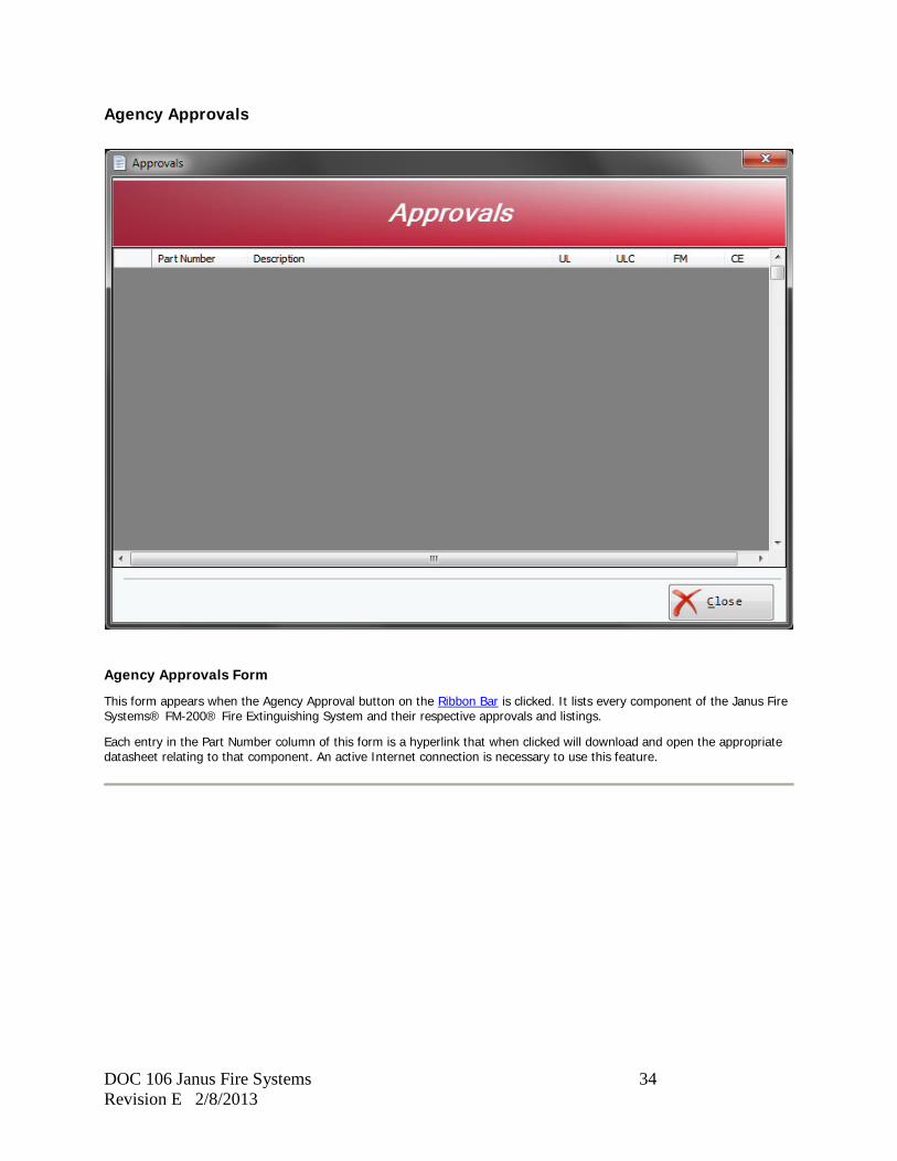
Agency Approvals Form
This form appears when the Agency Approval button on the Ribbon Bar is clicked. It lists every component of the Janus Fire Systems® FM-200® Fire Extinguishing System and their respective approvals and listings.
Each entry in the Part Number column of this form is a hyperlink that when clicked will download and open the appropriate datasheet relating to that component. An active Internet connection is necessary to use this feature.

DOC 106 Janus Fire Systems 35 Revision E 2/8/2013
FM-200 Design
DOC 106 Janus Fire Systems 36 Revision E 2/8/2013
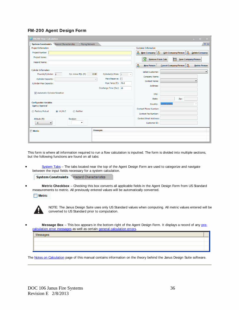
FM-200 Agent Design Form
This form is where all information required to run a flow calculation is inputted. The form is divided into multiple sections, but the following functions are found on all tabs:
• System Tabs – The tabs located near the top of the Agent Design Form are used to categorize and navigate between the input fields necessary for a system calculation.
• Metric Checkbox – Checking this box converts all applicable fields in the Agent Design Form from US Standard measurements to metric. All previously entered values will be automatically converted.
NOTE: The Janus Design Suite uses only US Standard values when computing. All metric values entered will be converted to US Standard prior to computation.
• Message Box – This box appears in the bottom right of the Agent Design Form. It displays a record of any pre-calculation error messages as well as certain general calculation errors.
The Notes on Calculation page of this manual contains information on the theory behind the Janus Design Suite software.
DOC 106 Janus Fire Systems 37 Revision E 2/8/2013
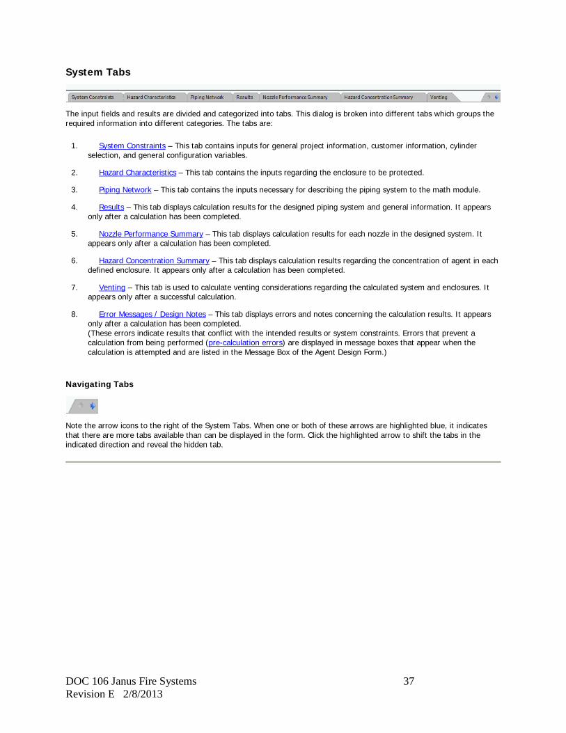
System Tabs
The input fields and results are divided and categorized into tabs. This dialog is broken into different tabs which groups the required information into different categories. The tabs are:
1. System Constraints – This tab contains inputs for general project information, customer information, cylinder selection, and general configuration variables.
2. Hazard Characteristics – This tab contains the inputs regarding the enclosure to be protected.
3. Piping Network – This tab contains the inputs necessary for describing the piping system to the math module.
4. Results – This tab displays calculation results for the designed piping system and general information. It appears only after a calculation has been completed.
5. Nozzle Performance Summary – This tab displays calculation results for each nozzle in the designed system. It appears only after a calculation has been completed.
6. Hazard Concentration Summary – This tab displays calculation results regarding the concentration of agent in each defined enclosure. It appears only after a calculation has been completed.
7. Venting – This tab is used to calculate venting considerations regarding the calculated system and enclosures. It appears only after a successful calculation.
8. Error Messages / Design Notes – This tab displays errors and notes concerning the calculation results. It appears only after a calculation has been completed. (These errors indicate results that conflict with the intended results or system constraints. Errors that prevent a calculation from being performed (pre-calculation errors) are displayed in message boxes that appear when the calculation is attempted and are listed in the Message Box of the Agent Design Form.)
Navigating Tabs
Note the arrow icons to the right of the System Tabs. When one or both of these arrows are highlighted blue, it indicates that there are more tabs available than can be displayed in the form. Click the highlighted arrow to shift the tabs in the indicated direction and reveal the hidden tab.
DOC 106 Janus Fire Systems 38 Revision E 2/8/2013
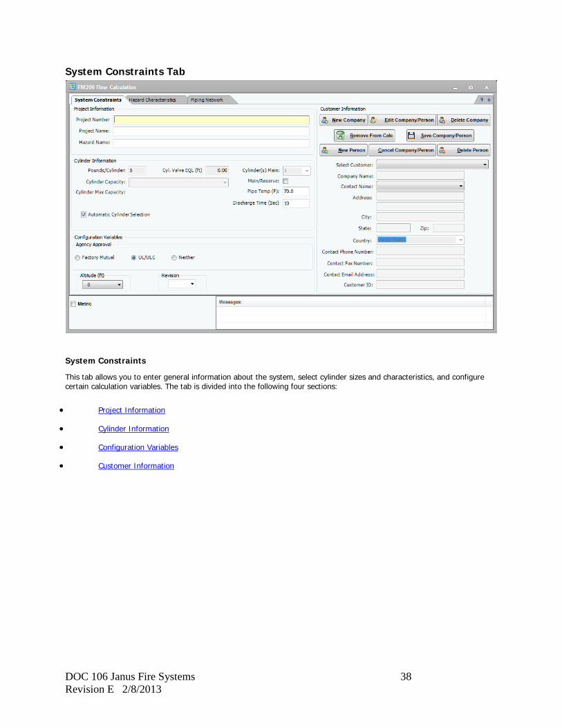
System Constraints Tab
System Constraints
This tab allows you to enter general information about the system, select cylinder sizes and characteristics, and configure certain calculation variables. The tab is divided into the following four sections:
• Project Information
• Cylinder Information
• Configuration Variables
• Customer Information
DOC 106 Janus Fire Systems 39 Revision E 2/8/2013
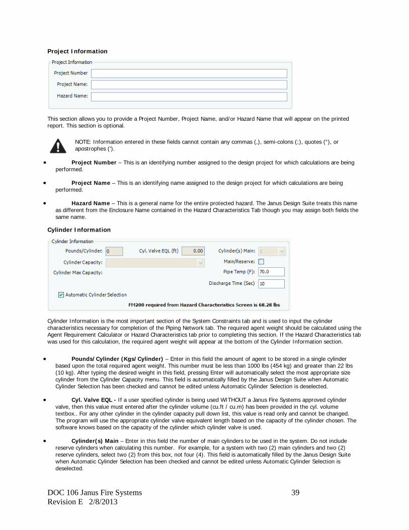
Project Information
This section allows you to provide a Project Number, Project Name, and/or Hazard Name that will appear on the printed report. This section is optional.
NOTE: Information entered in these fields cannot contain any commas (,), semi-colons (;), quotes (“), or apostrophes (‘).
• Project Number – This is an identifying number assigned to the design project for which calculations are being performed.
• Project Name – This is an identifying name assigned to the design project for which calculations are being performed.
• Hazard Name – This is a general name for the entire protected hazard. The Janus Design Suite treats this name as different from the Enclosure Name contained in the Hazard Characteristics Tab though you may assign both fields the same name.
Cylinder Information
Cylinder Information is the most important section of the System Constraints tab and is used to input the cylinder characteristics necessary for completion of the Piping Network tab. The required agent weight should be calculated using the Agent Requirement Calculator or Hazard Characteristics tab prior to completing this section. If the Hazard Characteristics tab was used for this calculation, the required agent weight will appear at the bottom of the Cylinder Information section.
• Pounds/Cylinder (Kgs/Cylinder) – Enter in this field the amount of agent to be stored in a single cylinder based upon the total required agent weight. This number must be less than 1000 lbs (454 kg) and greater than 22 lbs (10 kg). After typing the desired weight in this field, pressing Enter will automatically select the most appropriate size cylinder from the Cylinder Capacity menu. This field is automatically filled by the Janus Design Suite when Automatic Cylinder Selection has been checked and cannot be edited unless Automatic Cylinder Selection is deselected.
• Cyl. Valve EQL - If a user specified cylinder is being used WITHOUT a Janus Fire Systems approved cylinder valve, then this value must entered after the cylinder volume (cu.ft / cu.m) has been provided in the cyl. volume textbox.. For any other cylinder in the cylinder capacity pull down list, this value is read only and cannot be changed. The program will use the appropriate cylinder valve equivalent length based on the capacity of the cylinder chosen. The software knows based on the capacity of the cylinder which cylinder valve is used.
• Cylinder(s) Main – Enter in this field the number of main cylinders to be used in the system. Do not include reserve cylinders when calculating this number. For example, for a system with two (2) main cylinders and two (2) reserve cylinders, select two (2) from this box, not four (4). This field is automatically filled by the Janus Design Suite when Automatic Cylinder Selection has been checked and cannot be edited unless Automatic Cylinder Selection is deselected.
DOC 106 Janus Fire Systems 40 Revision E 2/8/2013
• Cylinder Capacity – Select from this menu the size cylinder to be used in the system. The recommended size is automatically chosen when the Pounds/Cylinder (Kgs/Cylinder) box is filled in. If a user specified cylinder is selected, refer to the Entering User Specified Cylinders section of this manual. This field is automatically filled by the Janus Design Suite when Automatic Cylinder Selection has been checked and cannot be edited unless Automatic Cylinder Selection is deselected.
• Cylinder Max Capacity – A number will appear next to this label based upon the cylinder selected from the Cylinder Capacity menu. The number entered into Pounds/Cylinder (Kgs/Cylinder) must be less than the Cylinder Max Capacity.
• Main/Reserve – Check this box if the system being designed uses a reserve supply of cylinders.
• Pipe Temp – Enter in this field the expected temperature of the main run of discharge piping during discharge. The default value is 70°F (21.1°C).
• Discharge Time – Enter in this field the intended duration in seconds for complete dispersal of agent from each nozzle. The default value is 10 seconds.
• Automatic Cylinder Selection – When this checkbox is selected, the Janus Design Suite will automatically select the most appropriate cylinder capacity, number of cylinders, and fill weight based upon the agent requirement determined using the Hazard Characteristics tab.
After completing the Cylinder Information section, the first section of pipe will be automatically entered into the Piping Network tab.
NOTE: Ideally, the storage cylinder should be located in an area where the ambient temperature is at least 60°F (15.6°C). Since systems are designed for a 70°F (21.1°C) storage condition, optimum performance can be expected if the storage area is kept near 70°F (21.1°C). For unbalanced systems, proper distribution and adequate system performance is approved for storage temperatures of 70°F ± 10°F (21.1°C ± 5.5°C). Calculations performed on systems where the cylinders are not maintained within this range may not be accurate and the required quantities of agent may not be discharged from one or more nozzles
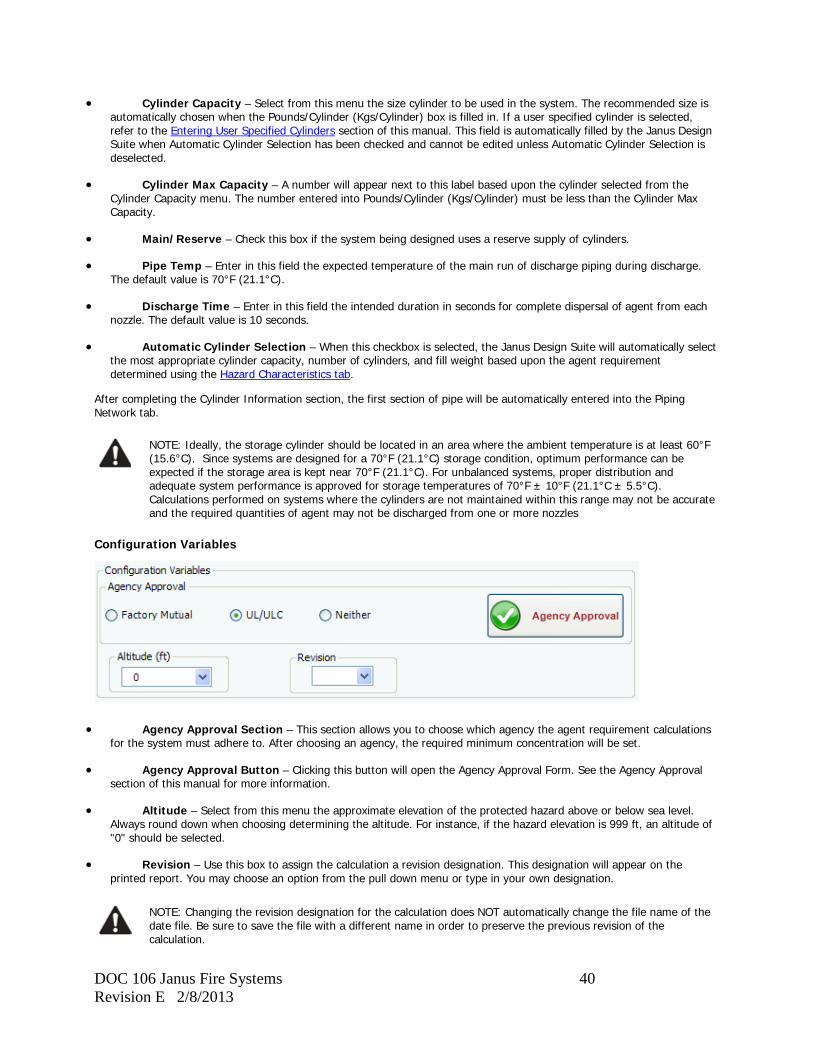
Configuration Variables
• Agency Approval Section – This section allows you to choose which agency the agent requirement calculations for the system must adhere to. After choosing an agency, the required minimum concentration will be set.
• Agency Approval Button – Clicking this button will open the Agency Approval Form. See the Agency Approval section of this manual for more information.
• Altitude – Select from this menu the approximate elevation of the protected hazard above or below sea level. Always round down when choosing determining the altitude. For instance, if the hazard elevation is 999 ft, an altitude of "0" should be selected.
• Revision – Use this box to assign the calculation a revision designation. This designation will appear on the printed report. You may choose an option from the pull down menu or type in your own designation.
NOTE: Changing the revision designation for the calculation does NOT automatically change the file name of the date file. Be sure to save the file with a different name in order to preserve the previous revision of the calculation.
DOC 106 Janus Fire Systems 41 Revision E 2/8/2013
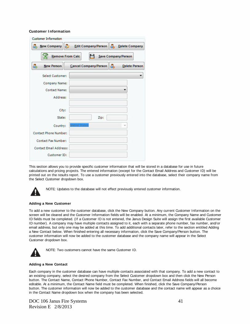
Customer Information
This section allows you to provide specific customer information that will be stored in a database for use in future calculations and pricing projects. The entered information (except for the Contact Email Address and Customer ID) will be printed out on the results report. To use a customer previously entered into the database, select their company name from the Select Customer dropdown box.
NOTE: Updates to the database will not effect previously entered customer information.
Adding a New Customer
To add a new customer to the customer database, click the New Company button. Any current Customer Information on the screen will be cleared and the Customer Information fields will be enabled. At a minimum, the Company Name and Customer ID fields must be completed. (If a Customer ID is not entered, the Janus Design Suite will assign the first available Customer ID number). A company may have multiple contacts assigned to it, each with a separate phone number, fax number, and/or email address, but only one may be added at this time. To add additional contacts later, refer to the section entitled Adding a New Contact below. When finished entering all necessary information, click the Save Company/Person button. The customer information will now be added to the customer database and the company name will appear in the Select Customer dropdown box.
NOTE: Two customers cannot have the same Customer ID.
Adding a New Contact
Each company in the customer database can have multiple contacts associated with that company. To add a new contact to an existing company, select the desired company from the Select Customer dropdown box and then click the New Person button. The Contact Name, Contact Phone Number, Contact Fax Number, and Contact Email Address fields will all become editable. At a minimum, the Contact Name field must be completed. When finished, click the Save Company/Person button. The customer information will now be added to the customer database and the contact name will appear as a choice in the Contact Name dropdown box when the company has been selected.
DOC 106 Janus Fire Systems 42 Revision E 2/8/2013
Removing a Customer from a Calculation
When initially created, no customer is assigned to the calculation. To return to this state again after a customer has been assigned, click the Remove From Calc button.
NOTE: Removing a customer from a proposal has no effect on the Janus Design Suite database. To remove a customer from the Janus Design Suite database, the Delete Customer button must be used.
Editing an Existing Customer/Contact
To edit an existing customer's information, select the company name from the Select Customer dropdown box. The current customer information will appear in the appropriate fields. Click the Edit Company/Person button and you will be able to modify this information. When modification is complete, click the Save Company/Person button. The updated information will be saved into the database replacing the previously saved information.
Deleting an Existing Contact
To delete an existing contact, select the company name from the Select Customer dropdown box and then the contact to be deleted from the Contact Name dropdown box. The current contact information will appear in the appropriate fields. Click the Delete Person button. You will be prompted to confirm the deletion. Click "yes" and the contact will be removed from the database. Should the contact information be needed at a later date, it will have to be reentered as described under Add a New Contact.
Deleting an Existing Customer
To delete an existing customer, select the company name from the Select Customer dropdown box. The current customer information will appear in the appropriate fields. Click the Delete Company button. You will be prompted to confirm the deletion. Click "yes" and the customer will be removed from the database. Should the customer information be needed at a later date, it will have to be reentered as described under Add a New Customer.
DOC 106 Janus Fire Systems 43 Revision E 2/8/2013
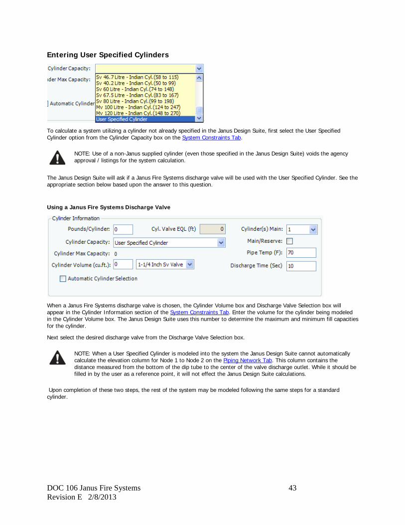
Entering User Specified Cylinders
To calculate a system utilizing a cylinder not already specified in the Janus Design Suite, first select the User Specified Cylinder option from the Cylinder Capacity box on the System Constraints Tab.
NOTE: Use of a non-Janus supplied cylinder (even those specified in the Janus Design Suite) voids the agency approval / listings for the system calculation.
The Janus Design Suite will ask if a Janus Fire Systems discharge valve will be used with the User Specified Cylinder. See the appropriate section below based upon the answer to this question.
Using a Janus Fire Systems Discharge Valve
When a Janus Fire Systems discharge valve is chosen, the Cylinder Volume box and Discharge Valve Selection box will appear in the Cylinder Information section of the System Constraints Tab. Enter the volume for the cylinder being modeled in the Cylinder Volume box. The Janus Design Suite uses this number to determine the maximum and minimum fill capacities for the cylinder.
Next select the desired discharge valve from the Discharge Valve Selection box.
NOTE: When a User Specified Cylinder is modeled into the system the Janus Design Suite cannot automatically calculate the elevation column for Node 1 to Node 2 on the Piping Network Tab. This column contains the distance measured from the bottom of the dip tube to the center of the valve discharge outlet. While it should be filled in by the user as a reference point, it will not effect the Janus Design Suite calculations.
Upon completion of these two steps, the rest of the system may be modeled following the same steps for a standard cylinder.
DOC 106 Janus Fire Systems 44 Revision E 2/8/2013
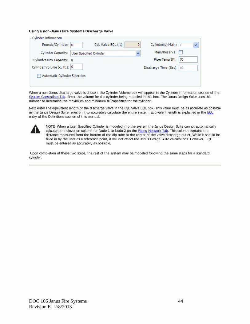
Using a non-Janus Fire Systems Discharge Valve
When a non-Janus discharge valve is chosen, the Cylinder Volume box will appear in the Cylinder Information section of the System Constraints Tab. Enter the volume for the cylinder being modeled in this box. The Janus Design Suite uses this number to determine the maximum and minimum fill capacities for the cylinder.
Next enter the equivalent length of the discharge valve in the Cyl. Valve EQL box. This value must be as accurate as possible as the Janus Design Suite relies on it to accurately calculate the entire system. Equivalent length is explained in the EQL entry of the Definitions section of this manual.
NOTE: When a User Specified Cylinder is modeled into the system the Janus Design Suite cannot automatically calculate the elevation column for Node 1 to Node 2 on the Piping Network Tab. This column contains the distance measured from the bottom of the dip tube to the center of the valve discharge outlet. While it should be filled in by the user as a reference point, it will not effect the Janus Design Suite calculations. However, EQL must be entered as accurately as possible.
Upon completion of these two steps, the rest of the system may be modeled following the same steps for a standard cylinder.
DOC 106 Janus Fire Systems 45 Revision E 2/8/2013
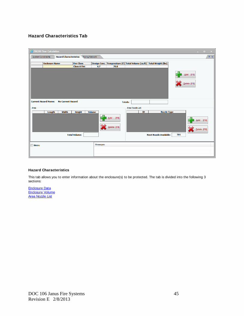
Hazard Characteristics Tab
Hazard Characteristics
This tab allows you to enter information about the enclosure(s) to be protected. The tab is divided into the following 3 sections:
Enclosure Data Enclosure Volume Area Nozzle List

DOC 106 Janus Fire Systems 46 Revision E 2/8/2013
Enclosure Data
This section is used to enter information about an enclosure and calculate the agent required to protect it.
• Enclosure Name – Enter in this field a name for the enclosure to be protected. If a room has a partition in it or is subdivided into multiple rooms that need to be protected, each partition or room must be listed under a separate enclosure name.
• Fire Class – Select from this dropdown box the type of hazard contained within the enclosure (Class A, Class B, or Class C). Selecting a Class B Fire will open the Flammables Concentration form from which to select the appropriate flammable. If more than one flammable will be stored in the enclosure, the flammable requiring the highest design concentration must be chosen. The required concentration will then be placed in the Design Concentration column for the enclosure.
• Design Concentration – Enter in this field the desired design concentration for the enclosure. If a Class B Fire has already been selected, this field will already contain the minimum design concentration for the selected flammable. If an Agency Approval has been selected from the System Constraints tab, this field will already contain the lowest acceptable design concentration the selected agency allows.
• Temperature – Enter in this field the ambient temperature for the protected enclosure. The default value is 70°F (21.1°C).
• Total Volume – This field will be filled with the calculated total enclosure volume based upon the information entered in the Enclosure Volume section of this tab.
• Total Weight – This field will be filled with the calculated agent weight required for the enclosure based upon the information entered in the Enclosure Volume section of this tab.
Once the necessary fields have been entered, clicking the Add button will add the enclosure to the system. To remove an enclosure from the system, make sure the unwanted row is highlighted and click the Delete button.
Enclosure Volume
This section is used to enter the dimensions of the enclosure and calculate its volume.
DOC 106 Janus Fire Systems 47 Revision E 2/8/2013
Entering a Volume
Input the length, width, and height of the enclosure in the appropriate columns. The Janus Design Suite will calculate the volume and place it the volume column of this section and the total volume column of the Enclosure Data section. If only the total volume is known, enter this measurement in the length field while keeping the width and height set at 1. Click the Add button to add the volume to the enclosure.
Deleting a Volume
To delete an entered volume, make sure the unwanted row is highlighted and click the Delete button.
Note on Irregular Shaped Enclosures
For nonrectangular enclosures, divide the enclosure space into rectangular sections and enter each section as a separate row. The Janus Design Suite will add all the volumes and place the sum in the Total Volume column of the Enclosure Data section.
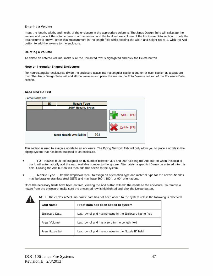
Area Nozzle List
This section is used to assign a nozzle to an enclosure. The Piping Network Tab will only allow you to place a nozzle in the piping system that has been assigned to an enclosure.
• ID – Nozzles must be assigned an ID number between 301 and 399. Clicking the Add button when this field is blank will automatically add the next available number to the system. Alternately, a specific ID may be entered into this field. Clicking the Add button will then add this nozzle to the system.
• Nozzle Type – Use this dropdown menu to assign an orientation type and material type for the nozzle. Nozzles may be brass or stainless steel (SST) and may have 360°, 180°, or 90° orientations.
Once the necessary fields have been entered, clicking the Add button will add the nozzle to the enclosure. To remove a nozzle from the enclosure, make sure the unwanted row is highlighted and click the Delete button.
NOTE: The enclosure/volume/nozzle data has not been added to the system unless the following is observed:
Grid Name Proof data has been added to system
Enclosure Data Last row of grid has no value in the Enclosure Name field
Area (Volume) Last row of grid has a zero in the Length field
Area Nozzle List Last row of grid has no value in the Nozzle ID field
DOC 106 Janus Fire Systems 48 Revision E 2/8/2013
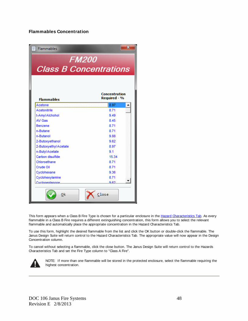
Flammables Concentration
This form appears when a Class B Fire Type is chosen for a particular enclosure in the Hazard Characteristics Tab. As every flammable in a Class B Fire requires a different extinguishing concentration, this form allows you to select the relevant flammable and automatically place the appropriate concentration in the Hazard Characteristics Tab.
To use this form, highlight the desired flammable from the list and click the OK button or double-click the flammable. The Janus Design Suite will return control to the Hazard Characteristics Tab. The appropriate value will now appear in the Design Concentration column.
To cancel without selecting a flammable, click the close button. The Janus Design Suite will return control to the Hazards Characteristics Tab and set the Fire Type column to "Class A Fire".
NOTE: If more than one flammable will be stored in the protected enclosure, select the flammable requiring the highest concentration.
DOC 106 Janus Fire Systems 49 Revision E 2/8/2013
Piping Network Tab
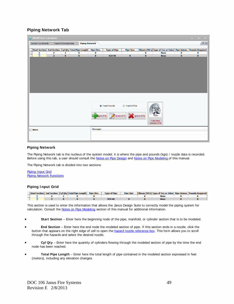
Piping Network
The Piping Network tab is the nucleus of the system model; it is where the pipe and pounds (kgs) / nozzle data is recorded. Before using this tab, a user should consult the Notes on Pipe Design and Notes on Pipe Modeling of this manual.
The Piping Network tab is divided into two sections:
Piping Input Grid Piping Network Functions
Piping Input Grid
This section is used to enter the information that allows the Janus Design Suite to correctly model the piping system for calculation. Consult the Notes on Pipe Modeling section of this manual for additional information.
• Start Section – Enter here the beginning node of the pipe, manifold, or cylinder section that is to be modeled.
• End Section – Enter here the end node the modeled section of pipe. If this section ends in a nozzle, click the button that appears on the right edge of cell to open the hazard nozzle reference box. This form allows you to scroll through the hazards and select the desired nozzle.
• Cyl Qty – Enter here the quantity of cylinders flowing through the modeled section of pipe by the time the end node has been reached.
• Total Pipe Length – Enter here the total length of pipe contained in the modeled section expressed in feet (meters), including any elevation changes.
DOC 106 Janus Fire Systems 50 Revision E 2/8/2013
• Pipe Elev – Enter here the change of elevation within the modeled section, expressed in feet (meters).
• A positive number indicates a rise in elevation.
• A negative number indicates a drop in elevation.
• A zero (0) indicates no change in elevation.
• Only one change of elevation is allowed per piping section.
• Type of Pipe – Enter here the type of pipe to be installed in the modeled section. The available types are accessible through the dropdown menu:
• SCH 40: Schedule 40 pipe with threaded fittings.
• WLD 40: Schedule 40 pipe with welded fittings.
• SCH 80: Schedule 80 pipe with threaded fittings.
• WLD 80: Schedule 80 pipe with welded fittings.
• GRV 40: Schedule 40 pipe with grooved fittings
• Any user specified pipes (see Custom Pipe Tables)
• Pipe Size – Enter here the nominal size of pipe in the modeled section. This value is set to zero by default. When set to zero, the calculation module will compute the pipe size required for the modeled section of pipe. To set a specific pipe size, click the cell and choose the desired size from the dropdown menu. Available sizes depend on the type of pipe selected.
• Elbows (90’s) – Enter here the number of 90 degree elbows used in the modeled section. 45 degree elbows should be entered as an equivalent number of 90 degree elbows. For instance, three 45 degree elbows are entered as 1.5.
• Type of Tee or Valve – Enter here the type of fitting used when a separation of agent flow is required for the section modeled or when the agent will be traveling thru a selector valve.
• None: This is the default value. Select this option if no tees are installed.
• Thru: Select this option if the modeled section begins with a thru tee. If the side branch of a tee is used to trip a pressure switch or pressure release, it should be treated as an equivalent number of 90 degree elbows and not as a tee. In this case, 1.0 would be added to the value entered in the Elbows field while Type of Tee would be set to none.
• Side: Select this option if the modeled section begins with a side tee. If one of the thru branches of a tee is used to trip a pressure switch or pressure release, it should be treated as an equivalent number of 90 degree elbows and not as a tee. In this case, 2.0 would be added to the value entered in the Elbows field while Type of Tee would be set to none.
• Blow Out: Select this option if a tee used in the modeled section is part of a blow out (i.e., the last nozzle on a branch line).
• Isolation Valve: Select this option when modeling an isolation valve. An isolation valve must be modeled so that the valve is on its own section of piping or so that the end node of its section is placed immediately following the valve.
• Selector Valve: Select this option when modeling a selector valve. You will be prompted whether you are modeling a Type A or Type B system with images that illustrate the difference between these two arrangements. (Refer to DOC102 Section 2.5 for more information.) Selecting Type A will return control to the Piping Network Tab. Selecting Type B will open the Manifold Dead Leg Selection Wizard used to model the selector valve(s). A selector valve must be modeled so that the valve is on its own section of piping or so that the end node of its section is placed immediately following the valve.
• Pipe Unions – Enter here the number of pipe unions and/or couplings used in the modeled section.
DOC 106 Janus Fire Systems 51 Revision E 2/8/2013
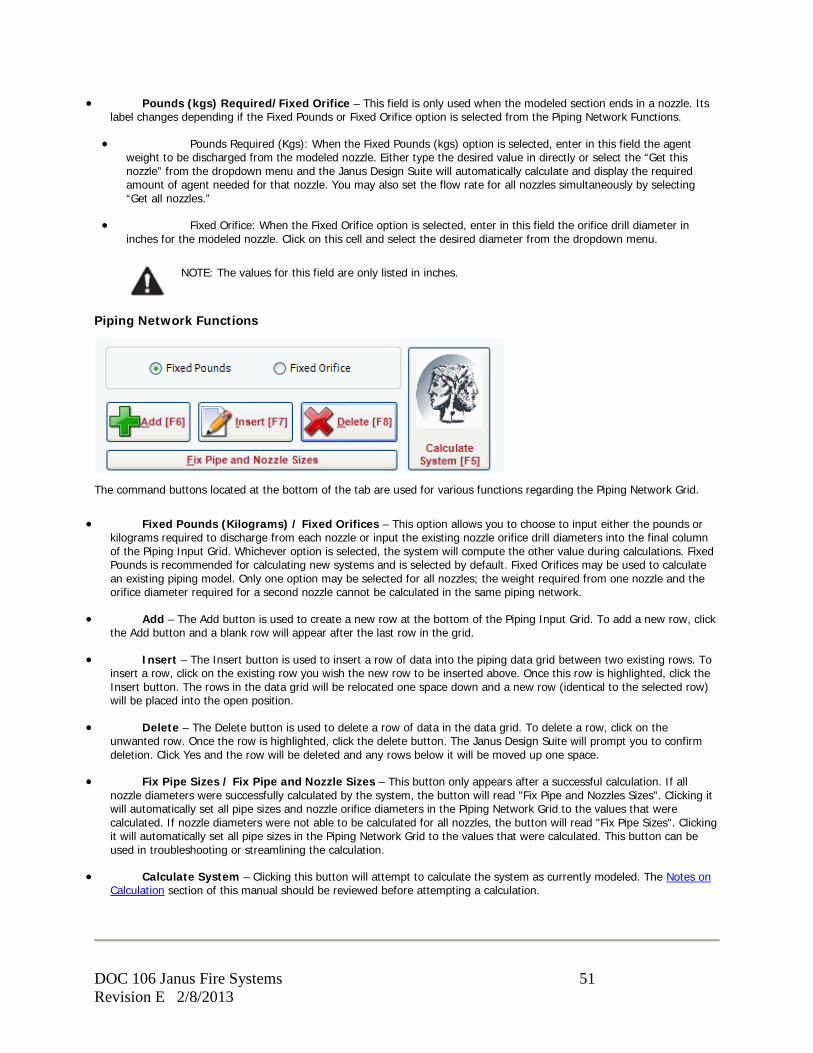
• Pounds (kgs) Required/Fixed Orifice – This field is only used when the modeled section ends in a nozzle. Its label changes depending if the Fixed Pounds or Fixed Orifice option is selected from the Piping Network Functions.
• Pounds Required (Kgs): When the Fixed Pounds (kgs) option is selected, enter in this field the agent weight to be discharged from the modeled nozzle. Either type the desired value in directly or select the “Get this nozzle” from the dropdown menu and the Janus Design Suite will automatically calculate and display the required amount of agent needed for that nozzle. You may also set the flow rate for all nozzles simultaneously by selecting “Get all nozzles.”
• Fixed Orifice: When the Fixed Orifice option is selected, enter in this field the orifice drill diameter in inches for the modeled nozzle. Click on this cell and select the desired diameter from the dropdown menu.
NOTE: The values for this field are only listed in inches.
Piping Network Functions
The command buttons located at the bottom of the tab are used for various functions regarding the Piping Network Grid.
• Fixed Pounds (Kilograms) / Fixed Orifices – This option allows you to choose to input either the pounds or kilograms required to discharge from each nozzle or input the existing nozzle orifice drill diameters into the final column of the Piping Input Grid. Whichever option is selected, the system will compute the other value during calculations. Fixed Pounds is recommended for calculating new systems and is selected by default. Fixed Orifices may be used to calculate an existing piping model. Only one option may be selected for all nozzles; the weight required from one nozzle and the orifice diameter required for a second nozzle cannot be calculated in the same piping network.
• Add – The Add button is used to create a new row at the bottom of the Piping Input Grid. To add a new row, click the Add button and a blank row will appear after the last row in the grid.
• Insert – The Insert button is used to insert a row of data into the piping data grid between two existing rows. To insert a row, click on the existing row you wish the new row to be inserted above. Once this row is highlighted, click the Insert button. The rows in the data grid will be relocated one space down and a new row (identical to the selected row) will be placed into the open position.
• Delete – The Delete button is used to delete a row of data in the data grid. To delete a row, click on the unwanted row. Once the row is highlighted, click the delete button. The Janus Design Suite will prompt you to confirm deletion. Click Yes and the row will be deleted and any rows below it will be moved up one space.
• Fix Pipe Sizes / Fix Pipe and Nozzle Sizes – This button only appears after a successful calculation. If all nozzle diameters were successfully calculated by the system, the button will read "Fix Pipe and Nozzles Sizes". Clicking it will automatically set all pipe sizes and nozzle orifice diameters in the Piping Network Grid to the values that were calculated. If nozzle diameters were not able to be calculated for all nozzles, the button will read "Fix Pipe Sizes". Clicking it will automatically set all pipe sizes in the Piping Network Grid to the values that were calculated. This button can be used in troubleshooting or streamlining the calculation.
• Calculate System – Clicking this button will attempt to calculate the system as currently modeled. The Notes on Calculation section of this manual should be reviewed before attempting a calculation.
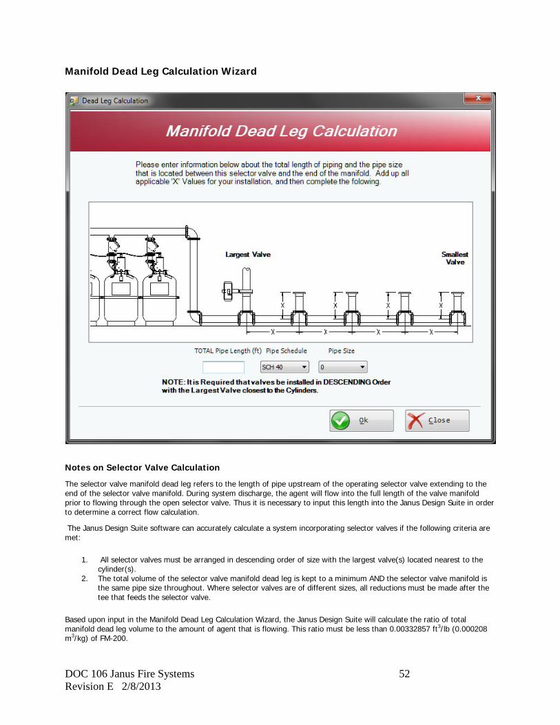
DOC 106 Janus Fire Systems 52 Revision E 2/8/2013
Manifold Dead Leg Calculation Wizard
Notes on Selector Valve Calculation
The selector valve manifold dead leg refers to the length of pipe upstream of the operating selector valve extending to the end of the selector valve manifold. During system discharge, the agent will flow into the full length of the valve manifold prior to flowing through the open selector valve. Thus it is necessary to input this length into the Janus Design Suite in order to determine a correct flow calculation.
The Janus Design Suite software can accurately calculate a system incorporating selector valves if the following criteria are met:
1. All selector valves must be arranged in descending order of size with the largest valve(s) located nearest to the cylinder(s).
2. The total volume of the selector valve manifold dead leg is kept to a minimum AND the selector valve manifold is the same pipe size throughout. Where selector valves are of different sizes, all reductions must be made after the tee that feeds the selector valve.
Based upon input in the Manifold Dead Leg Calculation Wizard, the Janus Design Suite will calculate the ratio of total manifold dead leg volume to the amount of agent that is flowing. This ratio must be less than 0.00332857 ft3/lb (0.000208 m3/kg) of FM-200.
DOC 106 Janus Fire Systems 53 Revision E 2/8/2013
Manifold Dead Leg Calculation Wizard Form
The Manifold Dead Leg Calculation Wizard appears when the user chooses ‘Selector Valve’ from the Tee/Valve field menu box on the Piping Network Tab. It will automatically insert the pipe schedule and pipe size of the previous entered line of data from the piping network screen. If your pipe size is not known, then simply enter a ‘0’ in the pipe size column.
• TOTAL Pipe Length (ft) – Enter in this field the total length of pipe located between the selector valve being modeled (operated) and the end of the manifold. This includes all pipe located between these two points that branches off from the manifold to a selector valve as measured from the centerline of the tee to the start of the valve. Each value that must be included in the calculation of this length is marked with an 'X' on the Manifold Dead Leg Calculation Wizard example diagram.
• Pipe Schedule – Select from this menu box the type of pipe used for the selector valve manifold. When the form opens, this box will automatically be populated with the pipe type entered in the Piping Network Tab for the previously modeled pipe section.
• Pipe Size – Select from this menu box the size of pipe used for the selector valve manifold. When the form opens, this box will automatically be populated with the pipe size entered in the Piping Network Tab for the previously modeled pipe section. If the valve manifold pipe size is unknown or you wish the Janus Design Suite to calculate the pipe size, select '0' from this menu.
NOTE: The pipe size entered in this field must be the size of the pipe in the manifold regardless of the pipe size of the selector valve being modeled. The size of the selector valve will be entered in the Pipe Size field of the Piping Network Tab for the section being modeled.
Notes on Selector Valve Modeling
When modeling selector valves using the Piping Network Tab of the Janus Design Suite, the following guidelines must be followed:
• A separate flow calculation must be performed on each of the selector valves in a system. [In the example below, the calculation being performed is for the selector valve located between nodes 6 and 7. The selector valve located between nodes 4 and 5 must be calculated separately.]
• For a section containing a selector valve, the first node is placed immediately before the tee and the second node is placed immediately after the valve.
• When a section of pipe contains a tee that branches off to a selector valve, that tee is entered into the Piping Network Tab as 3 elbows rather than as a Thru Tee. [In the example below, the section modeled between nodes 4 and 6 contains a tee that branches to the selector valve ending at node 5. Type of Tee is marked as 'None' for this section while the number of elbows is entered as 3.]
• All selector valves upstream of the selector valve being calculated are not entered into the Piping Network Tab for that calculation. [In the example below, the calculation being performed is for the selector valve located between nodes 6 and 7. The selector valve located between nodes 4 and 5 is not entered into the Piping Network Tab.]
• All selector valves downstream of the selector valve being calculated are not entered into the Piping Network Tab for that calculation but must be accounted for when completing the TOTAL Pipe Length field of the Manifold Dead Leg Calculation Wizard. [In the example below, the calculation being performed is for the selector valve located between nodes 6 and 7. This is the final selector valve in the manifold so only the length of pipe between node 6 and the end of the manifold is included in the TOTAL Pipe Length field of the Manifold Dead Leg Calculation Wizard for a total of 1'-0". If the calculation were being performed for the selector valve located between nodes 4 and 5, the length of pipe between node 4 and node 6 (a length of 4'-0"), node 6 and the end of the manifold (a length of 1'-0"), and node 6 to the start of the selector valve located immediately before node 7 (a length of 2'-0") must be included in the TOTAL Pipe Length field for a total of 7'-0".]
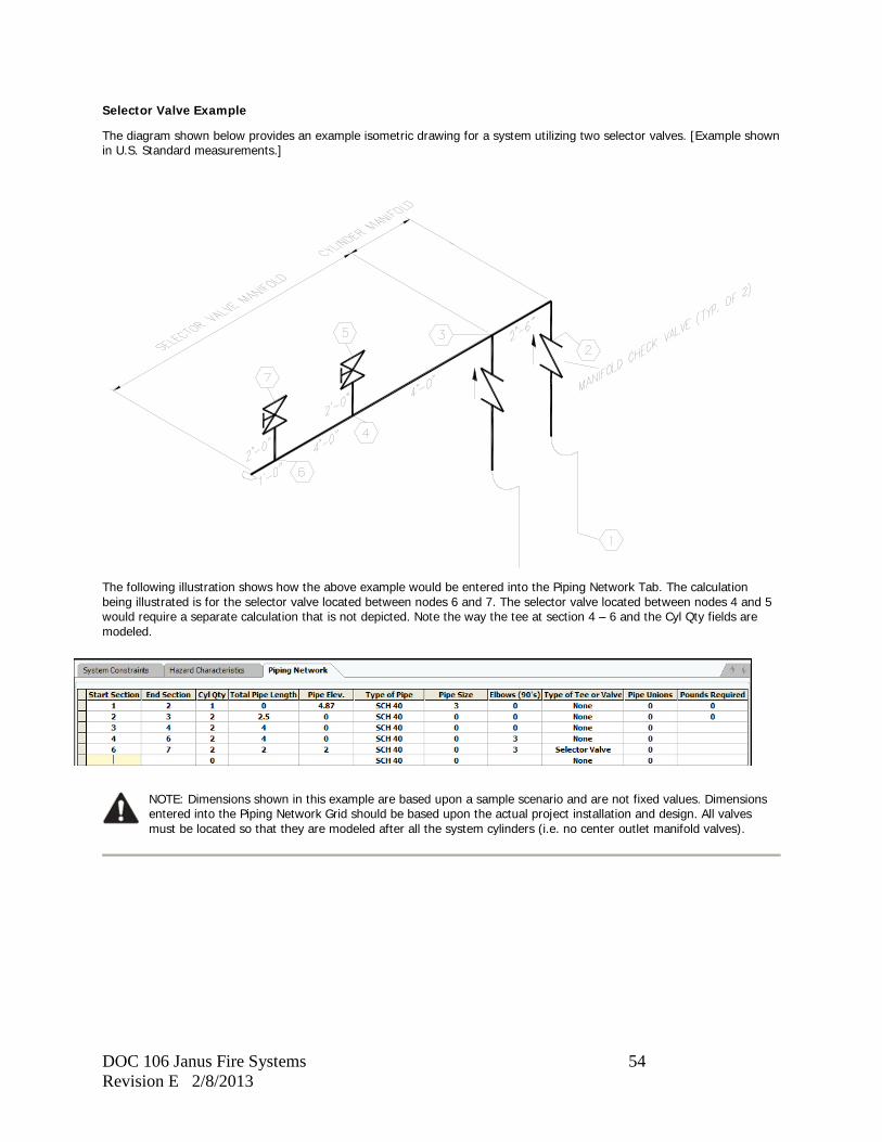
DOC 106 Janus Fire Systems 54 Revision E 2/8/2013
Selector Valve Example
The diagram shown below provides an example isometric drawing for a system utilizing two selector valves. [Example shown in U.S. Standard measurements.]
The following illustration shows how the above example would be entered into the Piping Network Tab. The calculation being illustrated is for the selector valve located between nodes 6 and 7. The selector valve located between nodes 4 and 5 would require a separate calculation that is not depicted. Note the way the tee at section 4 – 6 and the Cyl Qty fields are modeled.
NOTE: Dimensions shown in this example are based upon a sample scenario and are not fixed values. Dimensions entered into the Piping Network Grid should be based upon the actual project installation and design. All valves must be located so that they are modeled after all the system cylinders (i.e. no center outlet manifold valves).

DOC 106 Janus Fire Systems 55 Revision E 2/8/2013
System Design
This section lists the methods and guidelines necessary to properly design an engineered Janus Fire Systems® FM-200® Fire Extinguishing System. Also consult the Notes on Pipe Modeling and the Nozzles section of this manual.
Hazard Analysis
The first step in designing an engineered FM-200® total flooding system is to identify the unique requirements of the area to be protected.
Fuel Source
The design specifications for the FM-200® system are dependent on the hazard type, so it is first necessary to identify the type of hazard to be protected.
Hazard type is classified according to the combustible materials found in an area and may be considered Class A (wood, paper, cloth, rubber, and many plastics), Class B (flammable liquids and flammable gases), Class C (energized electrical equipment), or any combination of the three.
NFPA 2001 (2012 edition) requires the minimum design concentration for a Class A surface fire to be equal to 6.7% (7% for FM Approved systems), the minimum extinguishing concentration of heptane.
The minimum design concentration for a Class B fire depends on the extinguishing concentration for the specific fuel type found in the hazard plus a 30% safety factor. The minimum design concentrations for particular fuels based upon their cup burner extinguishing concentration are listed in Tables 3.1.1a and 3.1.1b in Appendix B of the Janus Fire Systems® FM-200® Operation, Design, and Service Manual DOC102.
The minimum design concentration for a Class C fire shall be 7.0% (7.8% for FM Approved systems), which is equal to the extinguishing concentration of Class A fuels times a safety factor of 1.35, in accordance with NFPA 2001 (2012 edition).
FM-200® design concentrations should be calculated according to the lowest expected ambient temperature within the protected area. When calculating the concentration levels for normally occupied spaces, the design concentration for FM-200® must not exceed the NOAEL (No Observed Adverse Effect Level) of 9% at the highest expected ambient temperature as stated in NFPA 2001.
Hazard Dimensions
Once the minimum design concentration is determined, the volume for the protected area must be calculated. Volume is determined by multiplying the area’s length by its width by its height (Volume = l x w x h).
The space below a raised floor (underfloor) must be included in the system design unless it is sealed from the room above. Separate nozzles are required for the underfloor and discharge should occur from both the room and underfloor nozzles simultaneously. All rooms located above a common unsealed underfloor must be protected by simultaneously operated systems to ensure minimum design concentration is reached.
If only the space under the raised floor is to be protected by a total flooding system, and it has openings between the space above and under the raised floor (including perforated floor tiles) then FM-200® should not be used, in accordance with NFPA 2001 (2012 edition).
If not shut down or closed automatically, the volume of the self-contained recirculating dampered ventilation systems ducts and components mounted below the ceiling height of the protected space must be considered as part of the total hazard volume when determining the quantity of agent.
Hazard Integrity
If a protected hazard is not sufficiently sealed, agent leakage may occur. Leakage of FM-200® may prevent the required concentration levels from being reached or maintained for the entire holding period, making it difficult for the FM-200® to extinguish the source of ignition. When a room opening does exist, adding more agent within a room to counter leakage may actually increase the rate of loss due to an increase in pressure created by the additional agent.
Doors should be checked for tightness. Weather stripping, seals, and door sweeps should be installed to minimize leakage. Any door required to remain open must be closed automatically prior to the discharge of the FM-200® agent.
Walls should be inspected for openings that could result in agent leakage. Openings or penetrations for cables or ducts should be permanently sealed. Joints where walls contact floors, other walls, and ceilings should be caulked or otherwise sealed. Caulking materials should be chosen based upon their elasticity and fire rating.
Ductwork leading into or out of the hazard area must contain dampers with airtight seals.
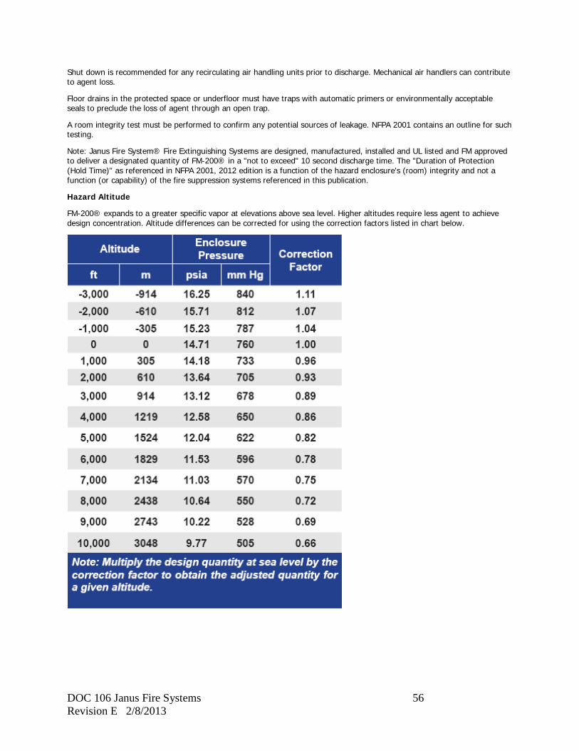
DOC 106 Janus Fire Systems 56 Revision E 2/8/2013
Shut down is recommended for any recirculating air handling units prior to discharge. Mechanical air handlers can contribute to agent loss.
Floor drains in the protected space or underfloor must have traps with automatic primers or environmentally acceptable seals to preclude the loss of agent through an open trap.
A room integrity test must be performed to confirm any potential sources of leakage. NFPA 2001 contains an outline for such testing.
Note: Janus Fire System® Fire Extinguishing Systems are designed, manufactured, installed and UL listed and FM approved to deliver a designated quantity of FM-200® in a "not to exceed" 10 second discharge time. The "Duration of Protection (Hold Time)" as referenced in NFPA 2001, 2012 edition is a function of the hazard enclosure's (room) integrity and not a function (or capability) of the fire suppression systems referenced in this publication.
Hazard Altitude
FM-200® expands to a greater specific vapor at elevations above sea level. Higher altitudes require less agent to achieve design concentration. Altitude differences can be corrected for using the correction factors listed in chart below.
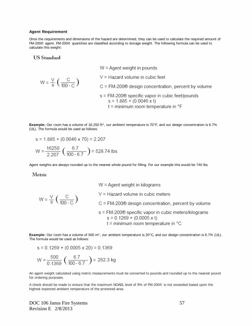
DOC 106 Janus Fire Systems 57 Revision E 2/8/2013
Agent Requirement
Once the requirements and dimensions of the hazard are determined, they can be used to calculate the required amount of FM-200® agent. FM-200® quantities are classified according to storage weight. The following formula can be used to calculate this weight:
Example: Our room has a volume of 16,250 ft³, our ambient temperature is 70°F, and our design concentration is 6.7% (UL). The formula would be used as follows:
Agent weights are always rounded up to the nearest whole pound for filling. For our example this would be 740 lbs.
Example: Our room has a volume of 500 m³, our ambient temperature is 20°C, and our design concentration is 6.7% (UL). The formula would be used as follows:
An agent weight calculated using metric measurements must be converted to pounds and rounded up to the nearest pound for ordering purposes.
A check should be made to ensure that the maximum NOAEL level of 9% of FM-200® is not exceeded based upon the highest expected ambient temperature of the protected area.
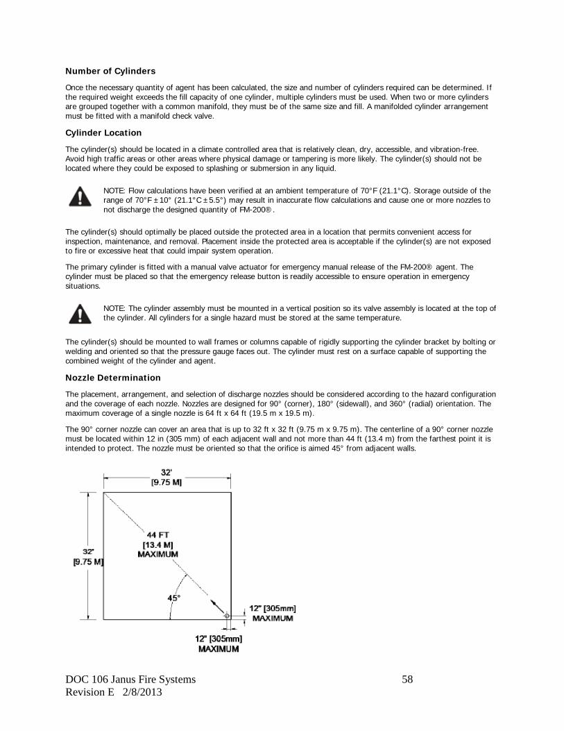
DOC 106 Janus Fire Systems 58 Revision E 2/8/2013
Number of Cylinders
Once the necessary quantity of agent has been calculated, the size and number of cylinders required can be determined. If the required weight exceeds the fill capacity of one cylinder, multiple cylinders must be used. When two or more cylinders are grouped together with a common manifold, they must be of the same size and fill. A manifolded cylinder arrangement must be fitted with a manifold check valve.
Cylinder Location
The cylinder(s) should be located in a climate controlled area that is relatively clean, dry, accessible, and vibration-free. Avoid high traffic areas or other areas where physical damage or tampering is more likely. The cylinder(s) should not be located where they could be exposed to splashing or submersion in any liquid.
NOTE: Flow calculations have been verified at an ambient temperature of 70°F (21.1°C). Storage outside of the range of 70°F ±10° (21.1°C ±5.5°) may result in inaccurate flow calculations and cause one or more nozzles to not discharge the designed quantity of FM-200®.
The cylinder(s) should optimally be placed outside the protected area in a location that permits convenient access for inspection, maintenance, and removal. Placement inside the protected area is acceptable if the cylinder(s) are not exposed to fire or excessive heat that could impair system operation.
The primary cylinder is fitted with a manual valve actuator for emergency manual release of the FM-200® agent. The cylinder must be placed so that the emergency release button is readily accessible to ensure operation in emergency situations.
NOTE: The cylinder assembly must be mounted in a vertical position so its valve assembly is located at the top of the cylinder. All cylinders for a single hazard must be stored at the same temperature.
The cylinder(s) should be mounted to wall frames or columns capable of rigidly supporting the cylinder bracket by bolting or welding and oriented so that the pressure gauge faces out. The cylinder must rest on a surface capable of supporting the combined weight of the cylinder and agent.
Nozzle Determination
The placement, arrangement, and selection of discharge nozzles should be considered according to the hazard configuration and the coverage of each nozzle. Nozzles are designed for 90° (corner), 180° (sidewall), and 360° (radial) orientation. The maximum coverage of a single nozzle is 64 ft x 64 ft (19.5 m x 19.5 m).
The 90° corner nozzle can cover an area that is up to 32 ft x 32 ft (9.75 m x 9.75 m). The centerline of a 90° corner nozzle must be located within 12 in (305 mm) of each adjacent wall and not more than 44 ft (13.4 m) from the farthest point it is intended to protect. The nozzle must be oriented so that the orifice is aimed 45° from adjacent walls.
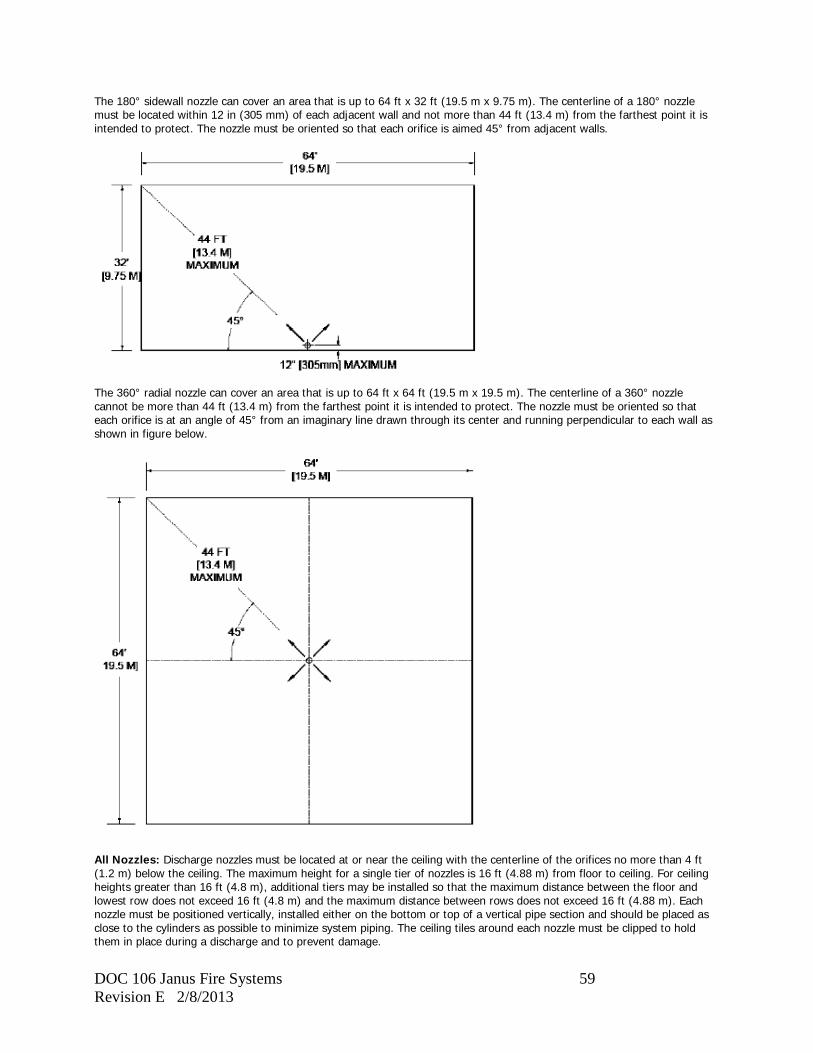
DOC 106 Janus Fire Systems 59 Revision E 2/8/2013
The 180° sidewall nozzle can cover an area that is up to 64 ft x 32 ft (19.5 m x 9.75 m). The centerline of a 180° nozzle must be located within 12 in (305 mm) of each adjacent wall and not more than 44 ft (13.4 m) from the farthest point it is intended to protect. The nozzle must be oriented so that each orifice is aimed 45° from adjacent walls.
The 360° radial nozzle can cover an area that is up to 64 ft x 64 ft (19.5 m x 19.5 m). The centerline of a 360° nozzle cannot be more than 44 ft (13.4 m) from the farthest point it is intended to protect. The nozzle must be oriented so that each orifice is at an angle of 45° from an imaginary line drawn through its center and running perpendicular to each wall as shown in figure below.
All Nozzles: Discharge nozzles must be located at or near the ceiling with the centerline of the orifices no more than 4 ft (1.2 m) below the ceiling. The maximum height for a single tier of nozzles is 16 ft (4.88 m) from floor to ceiling. For ceiling heights greater than 16 ft (4.8 m), additional tiers may be installed so that the maximum distance between the floor and lowest row does not exceed 16 ft (4.8 m) and the maximum distance between rows does not exceed 16 ft (4.88 m). Each nozzle must be positioned vertically, installed either on the bottom or top of a vertical pipe section and should be placed as close to the cylinders as possible to minimize system piping. The ceiling tiles around each nozzle must be clipped to hold them in place during a discharge and to prevent damage.
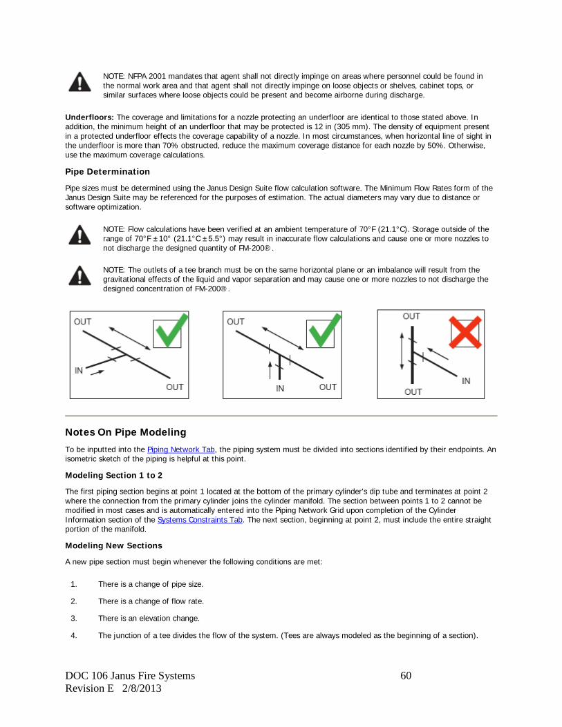
DOC 106 Janus Fire Systems 60 Revision E 2/8/2013
NOTE: NFPA 2001 mandates that agent shall not directly impinge on areas where personnel could be found in the normal work area and that agent shall not directly impinge on loose objects or shelves, cabinet tops, or similar surfaces where loose objects could be present and become airborne during discharge.
Underfloors: The coverage and limitations for a nozzle protecting an underfloor are identical to those stated above. In addition, the minimum height of an underfloor that may be protected is 12 in (305 mm). The density of equipment present in a protected underfloor effects the coverage capability of a nozzle. In most circumstances, when horizontal line of sight in the underfloor is more than 70% obstructed, reduce the maximum coverage distance for each nozzle by 50%. Otherwise, use the maximum coverage calculations.
Pipe Determination
Pipe sizes must be determined using the Janus Design Suite flow calculation software. The Minimum Flow Rates form of the Janus Design Suite may be referenced for the purposes of estimation. The actual diameters may vary due to distance or software optimization.
NOTE: Flow calculations have been verified at an ambient temperature of 70°F (21.1°C). Storage outside of the range of 70°F ±10° (21.1°C ±5.5°) may result in inaccurate flow calculations and cause one or more nozzles to not discharge the designed quantity of FM-200®.
NOTE: The outlets of a tee branch must be on the same horizontal plane or an imbalance will result from the gravitational effects of the liquid and vapor separation and may cause one or more nozzles to not discharge the designed concentration of FM-200®.
Notes On Pipe Modeling
To be inputted into the Piping Network Tab, the piping system must be divided into sections identified by their endpoints. An isometric sketch of the piping is helpful at this point.
Modeling Section 1 to 2
The first piping section begins at point 1 located at the bottom of the primary cylinder's dip tube and terminates at point 2 where the connection from the primary cylinder joins the cylinder manifold. The section between points 1 to 2 cannot be modified in most cases and is automatically entered into the Piping Network Grid upon completion of the Cylinder Information section of the Systems Constraints Tab. The next section, beginning at point 2, must include the entire straight portion of the manifold.
Modeling New Sections
A new pipe section must begin whenever the following conditions are met:
1. There is a change of pipe size.
2. There is a change of flow rate.
3. There is an elevation change.
4. The junction of a tee divides the flow of the system. (Tees are always modeled as the beginning of a section).
DOC 106 Janus Fire Systems 61 Revision E 2/8/2013
Modeling Nozzles
Nozzles are identified by a series of ID numbers from 301 to 399 as defined in the Area Nozzle List of the Hazard Characteristics tab. This number is entered as the end point of the section containing the nozzle.
Notes on Terminal Points
1. All terminal points should progress in logical numeric succession. The starting point (point 1) is located at the bottom of the first cylinder’s dip tube. From here the subsequent points are plotted moving toward the discharge nozzles.
2. A terminal point is placed upstream of (before) a tee where a division of flow occurs. Where flow is routed through only one branch of a tee (such as when the tee is used to trip a pressure switch), a terminal number can be omitted if none of the first three conditions for beginning a new section occurs.
3. A discharge or lock-out valve should be kept as close to the beginning of a section as possible (within approximately two feet). A discharge or lock-out valve can begin a section by placing the terminal point at the valve’s inlet.
4. Number the terminal points consecutively to the end of each distribution section. Do not duplicate terminal numbers on the same calculation.
Notes on Pipe Routing
The piping between storage containers and nozzles should be by the shortest route possible with a minimum of elbows and fittings. Every attempt should be made to keep the system in reasonable balance by supplying the nozzles from a central point if this can be done without substantially increasing the length and volume of the piping. The maximum pipe run permissible will be somewhat proportional to the total quantity of agent to be discharged. All piping elevation changes should be clearly indicated so that these will not be overlooked in flow calculations.
Notes on Elevation Difference
Any elevation differences between outlet tees exceeding 30 ft (9.1 m) are beyond the limitations set forth by the Underwriters Laboratories. Although sound engineering theory is used to predict pressure changes due to elevation, actual testing has not been performed outside of this range. Should this distance be exceeded, consideration should be given to rerouting piping to reduce elevation differences.
1. If nozzles are located above the discharge outlet, then the maximum elevation difference between the discharge outlet and the highest horizontal pipe run or discharge nozzle (whichever is highest) shall not exceed 30 feet (9.1 m).
2. If nozzles are only located below the discharge outlet, then the maximum elevation difference between the discharge outlet and the lowest horizontal pipe run or discharge nozzle (whichever is lowest) shall not exceed 30 feet (9.1 m).
3. If nozzles are located both above and below the discharge outlet, then the maximum elevation difference between the highest horizontal pipe run or discharge nozzle (whichever is highest) and the lowest horizontal pipe run or discharge nozzle (whichever is lowest) shall not exceed 30 feet (9.1 m).
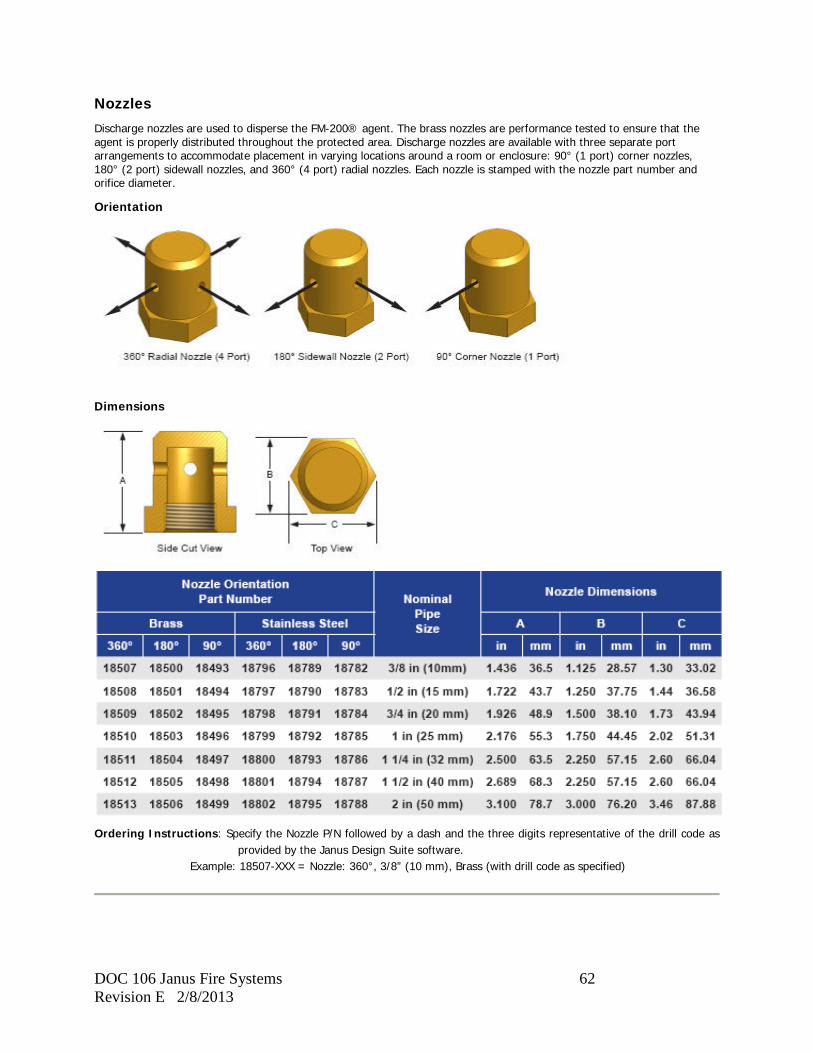
DOC 106 Janus Fire Systems 62 Revision E 2/8/2013
Nozzles Discharge nozzles are used to disperse the FM-200® agent. The brass nozzles are performance tested to ensure that the agent is properly distributed throughout the protected area. Discharge nozzles are available with three separate port arrangements to accommodate placement in varying locations around a room or enclosure: 90° (1 port) corner nozzles, 180° (2 port) sidewall nozzles, and 360° (4 port) radial nozzles. Each nozzle is stamped with the nozzle part number and orifice diameter.
Orientation
Dimensions
Ordering Instructions: Specify the Nozzle P/N followed by a dash and the three digits representative of the drill code as
provided by the Janus Design Suite software. Example: 18507-XXX = Nozzle: 360°, 3/8” (10 mm), Brass (with drill code as specified)
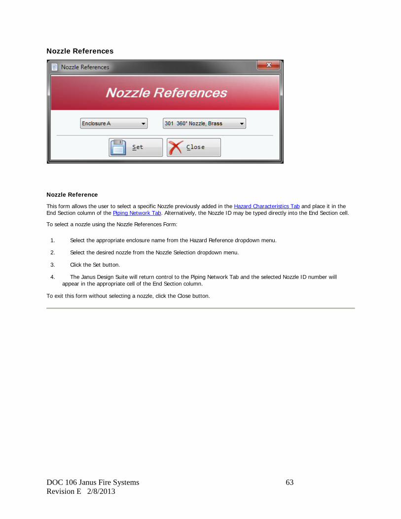
DOC 106 Janus Fire Systems 63 Revision E 2/8/2013
Nozzle References
Nozzle Reference
This form allows the user to select a specific Nozzle previously added in the Hazard Characteristics Tab and place it in the End Section column of the Piping Network Tab. Alternatively, the Nozzle ID may be typed directly into the End Section cell.
To select a nozzle using the Nozzle References Form:
1. Select the appropriate enclosure name from the Hazard Reference dropdown menu.
2. Select the desired nozzle from the Nozzle Selection dropdown menu.
3. Click the Set button.
4. The Janus Design Suite will return control to the Piping Network Tab and the selected Nozzle ID number will appear in the appropriate cell of the End Section column.
To exit this form without selecting a nozzle, click the Close button.
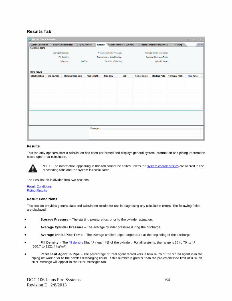
DOC 106 Janus Fire Systems 64 Revision E 2/8/2013
Results Tab
Results
This tab only appears after a calculation has been performed and displays general system information and piping information based upon that calculation.
NOTE: The information appearing in this tab cannot be edited unless the system characteristics are altered in the proceeding tabs and the system is recalculated.
The Results tab is divided into two sections:
Result Conditions Piping Results
Result Conditions
This section provides general data and calculation results for use in diagnosing any calculation errors. The following fields are displayed:
• Storage Pressure – The starting pressure just prior to the cylinder actuation.
• Average Cylinder Pressure – The average cylinder pressure during the discharge.
• Average Initial Pipe Temp – The average ambient pipe temperature at the beginning of the discharge.
• Fill Density – The fill density [lbs/ft³ (kgs/m³)] of the cylinder. For all systems, the range is 35 to 70 lb/ft³ (560.7 to 1121.4 kg/m³).
• Percent of Agent in Pipe – The percentage of total agent stored versus how much of the stored agent is in the piping network prior to the nozzles discharging liquid. If this number is greater than the pre-established limit of 80% an error message will appear in the Error Messages tab.
DOC 106 Janus Fire Systems 65 Revision E 2/8/2013
• Average Discharge Time – This value represents the average discharge time of all of the nozzles in seconds. If this number is not between 5 seconds and 10 seconds, an error message will appear in the Error Messages tab.
• Cylinders – The quantity of cylinders modeled.
• lbs/Cyl (Kgs/Cyl) – The quantity of agent fluid within an individual cylinder.
• Total lbs (kgs) of FM-200 – The total amount of FM-200 within all the cylinders.
• Cylinder Type – The type of cylinder selected for the calculation.
Piping Results
This section displays flow and pressure calculations for each of the piping sections that were defined in the Piping Network Tab. The following columns are displayed:
• Start Section – The starting node for the modeled section of the piping network.
• End Section – The ending node for the modeled section of the piping network.
• Nominal Pipe Size – The user inputted or system calculated pipe size and schedule for the modeled section of pipe.
• Pipe Length – Total length of pipe within the section, including elevation changes.
• Pipe Elev – The total elevation change within the modeled section of pipe.
• EQL – Total equivalent length of the modeled section of pipe. This includes pipe, elbows, tees, couplings, unions, valves, and any additional information inputted into the piping network as elbows (i.e. non-flowing tees for pressure trips, etc.)
• Tee or Valve – This displays the type of tee or valve (if any) found in the modeled section of pipe.
• Starting PSIG (Bar) – The pressure at the beginning of the modeled section of pipe.
• Terminal PSIG (Bar) – The pressure at the end of the modeled section of pipe.
• Flow Rate – The calculated flow rate through the modeled section of pipe.

DOC 106 Janus Fire Systems 66 Revision E 2/8/2013
Nozzle Performance Summary Tab
Nozzle Performance Summary
This tab only appears after a calculation has been performed and displays information and calculation results for each nozzle modeled in the system. Nozzles are listed in the order they occur in the piping network.
NOTE: The information appearing in this tab cannot be edited unless the system characteristics are altered in the proceeding tabs and the system is recalculated.
The following columns are displayed in this tab:
• Nozzle ID – The identification number given to the modeled nozzle in the Hazard Characteristics tab.
• Pipe Size – The user inputted or system calculated size and schedule of the modeled nozzle.
• Stock Number – The Janus Fire Systems™ part number for the modeled nozzle.
• Style – The orientation and material type of the modeled nozzle.
• Drill Diameter – The specific drill diameter in inches for each of the nozzle ports.
• Drill Size – The industry designation for the required drill diameter.
• Total Orifice Area – The total single orifice area (the area of each orifice added up together) for the modeled nozzle.
• FM-200 Discharged – The quantity of FM-200 discharged through the modeled nozzle.
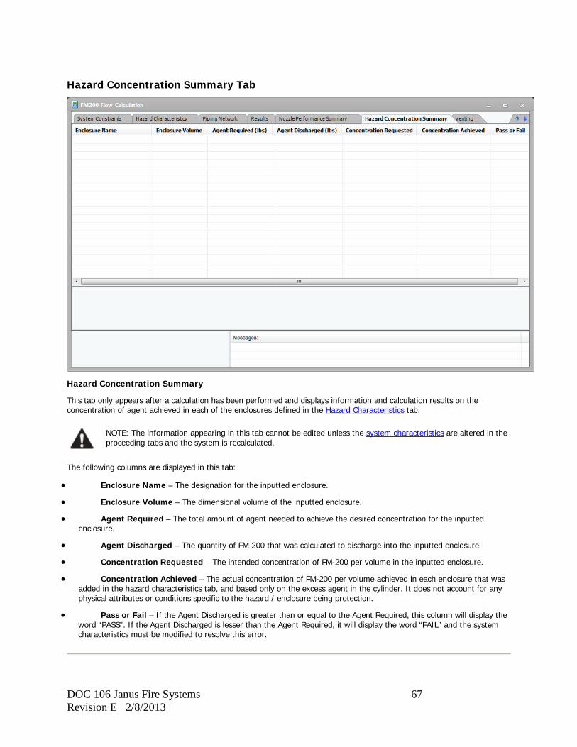
DOC 106 Janus Fire Systems 67 Revision E 2/8/2013
Hazard Concentration Summary Tab
Hazard Concentration Summary
This tab only appears after a calculation has been performed and displays information and calculation results on the concentration of agent achieved in each of the enclosures defined in the Hazard Characteristics tab.
NOTE: The information appearing in this tab cannot be edited unless the system characteristics are altered in the proceeding tabs and the system is recalculated.
The following columns are displayed in this tab:
• Enclosure Name – The designation for the inputted enclosure.
• Enclosure Volume – The dimensional volume of the inputted enclosure.
• Agent Required – The total amount of agent needed to achieve the desired concentration for the inputted enclosure.
• Agent Discharged – The quantity of FM-200 that was calculated to discharge into the inputted enclosure.
• Concentration Requested – The intended concentration of FM-200 per volume in the inputted enclosure.
• Concentration Achieved – The actual concentration of FM-200 per volume achieved in each enclosure that was added in the hazard characteristics tab, and based only on the excess agent in the cylinder. It does not account for any physical attributes or conditions specific to the hazard / enclosure being protection.
• Pass or Fail – If the Agent Discharged is greater than or equal to the Agent Required, this column will display the word “PASS”. If the Agent Discharged is lesser than the Agent Required, it will display the word “FAIL” and the system characteristics must be modified to resolve this error.
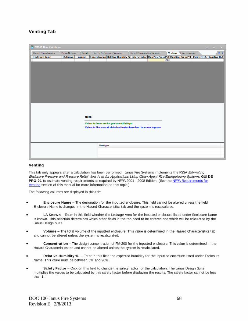
DOC 106 Janus Fire Systems 68 Revision E 2/8/2013
Venting Tab
Venting
This tab only appears after a calculation has been performed. Janus Fire Systems implements the FSSA Estimating Enclosure Pressure and Pressure Relief Vent Area for Applications Using Clean Agent Fire Extinguishing Systems, GUIDE PRG-01 to estimate venting requirements as required by NFPA 2001 - 2008 Edition. (See the NFPA Requirements for Venting section of this manual for more information on this topic.)
The following columns are displayed in this tab:
• Enclosure Name – The designation for the inputted enclosure. This field cannot be altered unless the field Enclosure Name is changed in the Hazard Characteristics tab and the system is recalculated.
• LA Known – Enter in this field whether the Leakage Area for the inputted enclosure listed under Enclosure Name is known. This selection determines which other fields in the tab need to be entered and which will be calculated by the Janus Design Suite.
• Volume – The total volume of the inputted enclosure. This value is determined in the Hazard Characteristics tab and cannot be altered unless the system is recalculated.
• Concentration – The design concentration of FM-200 for the inputted enclosure. This value is determined in the Hazard Characteristics tab and cannot be altered unless the system is recalculated.
• Relative Humidity % – Enter in this field the expected humidity for the inputted enclosure listed under Enclosure Name. This value must be between 5% and 90%.
• Safety Factor – Click on this field to change the safety factor for the calculation. The Janus Design Suite multiplies the values to be calculated by this safety factor before displaying the results. The safety factor cannot be less than 1.
DOC 106 Janus Fire Systems 69 Revision E 2/8/2013
• Max. Pos. Pressure PSF (Pa) – The maximum positive pressure the inputted enclosure can withstand in pounds per square foot (pascal). If "Yes" was selected in the LA Known field, this value will be calculated from the value entered in the Positive ELA field. Otherwise, enter this value to determine the Positive ELA.
• Max. Neg. Pressure PSF (Pa) – The maximum negative pressure the inputted enclosure can withstand in pounds per square foot (pascal). If "Yes" was selected in the LA Known field, this value will be calculated from the value entered in the Negative ELA field. Otherwise, enter this value to determine the Negative ELA.
• Positive ELA – The positive equivalent leakage area for the inputted enclosure. If "No" was selected in the LA Known field, the required positive ELA will be calculated from the value entered in the Max. Pos. Pressure PSF (Pa) field. Otherwise, enter this value to determine the Max. Pos. Pressure PSF.
• Negative ELA – The negative equivalent leakage area for the inputted enclosure. If "No" was selected in the LA Known field, the required negative ELA will be calculated from the value entered in the Max. Neg. Pressure PSF (Pa) field. Otherwise, enter this value to determine the Max. Neg. Pressure PSF.
NFPA Requirements for Venting
NFPA 2001 requires working plans to show the following items pertaining to the design of the system:
• For an enclosure protected by a clean agent fire extinguishing system an estimate of the maximum positive and the maximum negative pressure, relative to ambient pressure, expected to be developed upon the discharge of agent.
• Pressure relief vent area, or equivalent leakage area, for the protected enclosure to prevent development, during system discharge, of a pressure difference across the enclosure boundaries that exceeds a specified enclosure pressure limit.
The Venting Tab of the FM-200 Agent Design Form can be used to estimate the maximum positive and negative pressures for an inputted enclosure based upon its equivalent leakage area, or else the equivalent leakage area required to prevent the maximum positive and negative pressures from being surpassed.
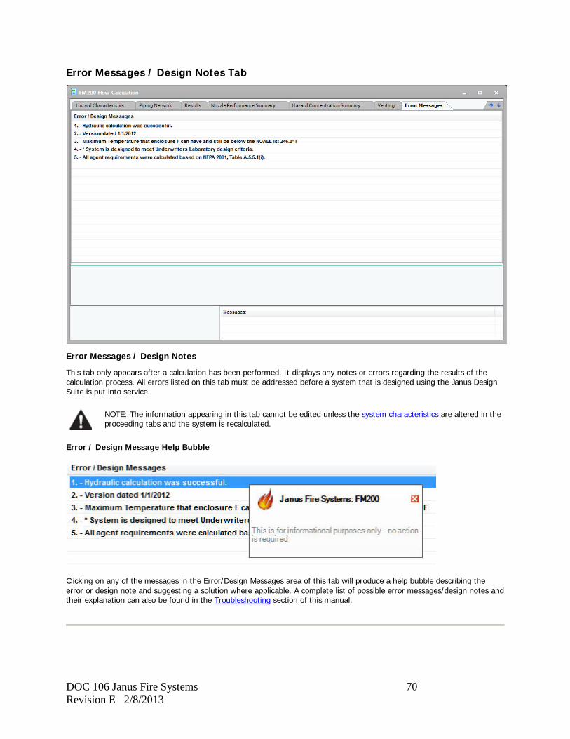
DOC 106 Janus Fire Systems 70 Revision E 2/8/2013
Error Messages / Design Notes Tab
Error Messages / Design Notes
This tab only appears after a calculation has been performed. It displays any notes or errors regarding the results of the calculation process. All errors listed on this tab must be addressed before a system that is designed using the Janus Design Suite is put into service.
NOTE: The information appearing in this tab cannot be edited unless the system characteristics are altered in the proceeding tabs and the system is recalculated.
Error / Design Message Help Bubble
Clicking on any of the messages in the Error/Design Messages area of this tab will produce a help bubble describing the error or design note and suggesting a solution where applicable. A complete list of possible error messages/design notes and their explanation can also be found in the Troubleshooting section of this manual.
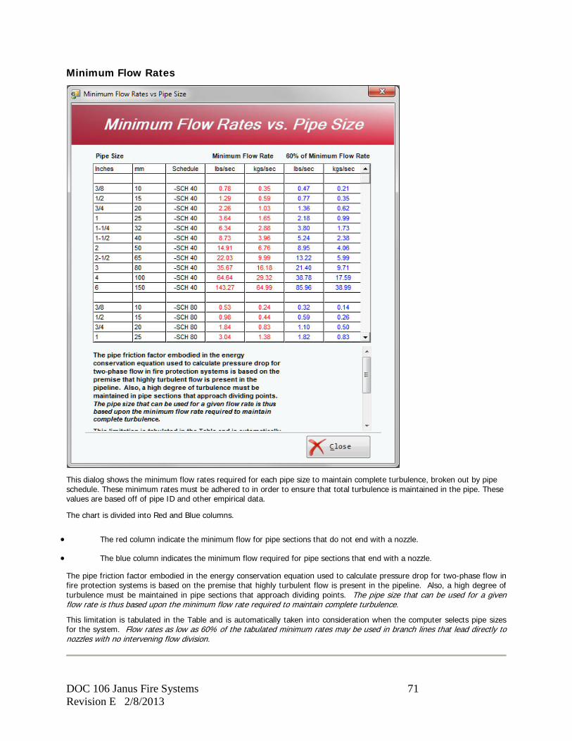
DOC 106 Janus Fire Systems 71 Revision E 2/8/2013
Minimum Flow Rates
This dialog shows the minimum flow rates required for each pipe size to maintain complete turbulence, broken out by pipe schedule. These minimum rates must be adhered to in order to ensure that total turbulence is maintained in the pipe. These values are based off of pipe ID and other empirical data.
The chart is divided into Red and Blue columns.
• The red column indicate the minimum flow for pipe sections that do not end with a nozzle.
• The blue column indicates the minimum flow required for pipe sections that end with a nozzle.
The pipe friction factor embodied in the energy conservation equation used to calculate pressure drop for two-phase flow in fire protection systems is based on the premise that highly turbulent flow is present in the pipeline. Also, a high degree of turbulence must be maintained in pipe sections that approach dividing points. The pipe size that can be used for a given flow rate is thus based upon the minimum flow rate required to maintain complete turbulence.
This limitation is tabulated in the Table and is automatically taken into consideration when the computer selects pipe sizes for the system. Flow rates as low as 60% of the tabulated minimum rates may be used in branch lines that lead directly to nozzles with no intervening flow division.

DOC 106 Janus Fire Systems 72 Revision E 2/8/2013
Notes on Calculation
Both pipe and nozzles are sized using this computer program. The Janus Design Suite is based on recognized hydraulic theory as detailed in the Flow Theory section of this manual and the results of the program have been verified in rigorous laboratory tests. Calculations made with the Janus Design Suite are FM approved and UL/ULC listed when used within the limitations programmed into the Janus Design Suite and detailed within this manual.
Caution
Flow calculations have been verified at an ambient temperature of 70°F ±10°F (21.1°C ±5.5°C). Storage of agent cylinders outside of the range of 70°F ±10°F (21.1°C ±5.5°C) may result in inaccurate flow calculations and cause one or more nozzles to not discharge the designed quantity of FM-200.
Error Checking
While the calculations the Janus Design Suite uses for determining pipe and orifice sizes cannot be checked manually, the data inputted into the Janus Design Suite must be reviewed for accuracy. On-site job conditions must be reviewed and the system as calculated must be checked for consistency with the system as installed. All of this does not preclude the desirability of an actual discharge test on the installed system to check for unanticipated circumstances that might influence overall system performance.
The Janus Design Suite performs intense pre-calculation error checking. Should any obvious input errors be found, a message box detailing the error will be displayed and the error message will appear in the Message List box in the lower right corner of the Agent Design Form. The Pre-Calculation Error Messages section of this manual contains a complete list and explanation of all possible errors.
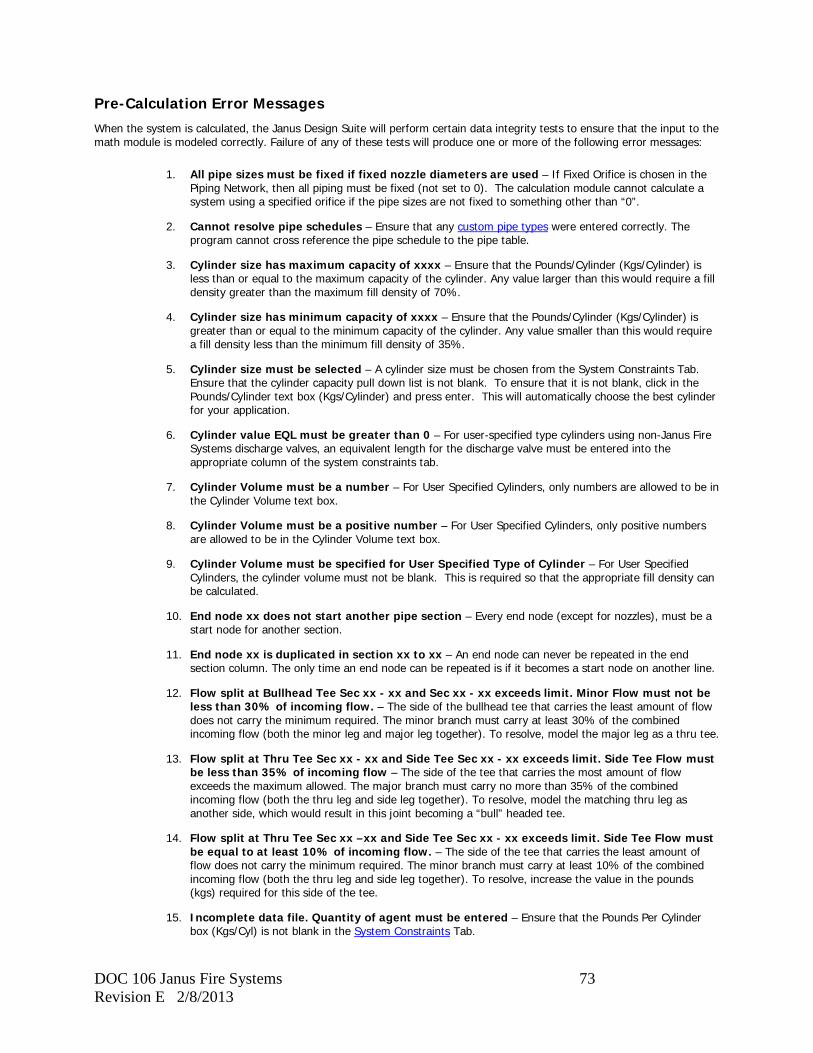
DOC 106 Janus Fire Systems 73 Revision E 2/8/2013
Pre-Calculation Error Messages
When the system is calculated, the Janus Design Suite will perform certain data integrity tests to ensure that the input to the math module is modeled correctly. Failure of any of these tests will produce one or more of the following error messages:
1. All pipe sizes must be fixed if fixed nozzle diameters are used – If Fixed Orifice is chosen in the Piping Network, then all piping must be fixed (not set to 0). The calculation module cannot calculate a system using a specified orifice if the pipe sizes are not fixed to something other than “0”.
2. Cannot resolve pipe schedules – Ensure that any custom pipe types were entered correctly. The program cannot cross reference the pipe schedule to the pipe table.
3. Cylinder size has maximum capacity of xxxx – Ensure that the Pounds/Cylinder (Kgs/Cylinder) is less than or equal to the maximum capacity of the cylinder. Any value larger than this would require a fill density greater than the maximum fill density of 70%.
4. Cylinder size has minimum capacity of xxxx – Ensure that the Pounds/Cylinder (Kgs/Cylinder) is greater than or equal to the minimum capacity of the cylinder. Any value smaller than this would require a fill density less than the minimum fill density of 35%.
5. Cylinder size must be selected – A cylinder size must be chosen from the System Constraints Tab. Ensure that the cylinder capacity pull down list is not blank. To ensure that it is not blank, click in the Pounds/Cylinder text box (Kgs/Cylinder) and press enter. This will automatically choose the best cylinder for your application.
6. Cylinder value EQL must be greater than 0 – For user-specified type cylinders using non-Janus Fire Systems discharge valves, an equivalent length for the discharge valve must be entered into the appropriate column of the system constraints tab.
7. Cylinder Volume must be a number – For User Specified Cylinders, only numbers are allowed to be in the Cylinder Volume text box.
8. Cylinder Volume must be a positive number – For User Specified Cylinders, only positive numbers are allowed to be in the Cylinder Volume text box.
9. Cylinder Volume must be specified for User Specified Type of Cylinder – For User Specified Cylinders, the cylinder volume must not be blank. This is required so that the appropriate fill density can be calculated.
10. End node xx does not start another pipe section – Every end node (except for nozzles), must be a start node for another section.
11. End node xx is duplicated in section xx to xx – An end node can never be repeated in the end section column. The only time an end node can be repeated is if it becomes a start node on another line.
12. Flow split at Bullhead Tee Sec xx - xx and Sec xx - xx exceeds limit. Minor Flow must not be less than 30% of incoming flow. – The side of the bullhead tee that carries the least amount of flow does not carry the minimum required. The minor branch must carry at least 30% of the combined incoming flow (both the minor leg and major leg together). To resolve, model the major leg as a thru tee.
13. Flow split at Thru Tee Sec xx - xx and Side Tee Sec xx - xx exceeds limit. Side Tee Flow must be less than 35% of incoming flow – The side of the tee that carries the most amount of flow exceeds the maximum allowed. The major branch must carry no more than 35% of the combined incoming flow (both the thru leg and side leg together). To resolve, model the matching thru leg as another side, which would result in this joint becoming a “bull” headed tee.
14. Flow split at Thru Tee Sec xx –xx and Side Tee Sec xx - xx exceeds limit. Side Tee Flow must be equal to at least 10% of incoming flow. – The side of the tee that carries the least amount of flow does not carry the minimum required. The minor branch must carry at least 10% of the combined incoming flow (both the thru leg and side leg together). To resolve, increase the value in the pounds (kgs) required for this side of the tee.
15. Incomplete data file. Quantity of agent must be entered – Ensure that the Pounds Per Cylinder box (Kgs/Cyl) is not blank in the System Constraints Tab.
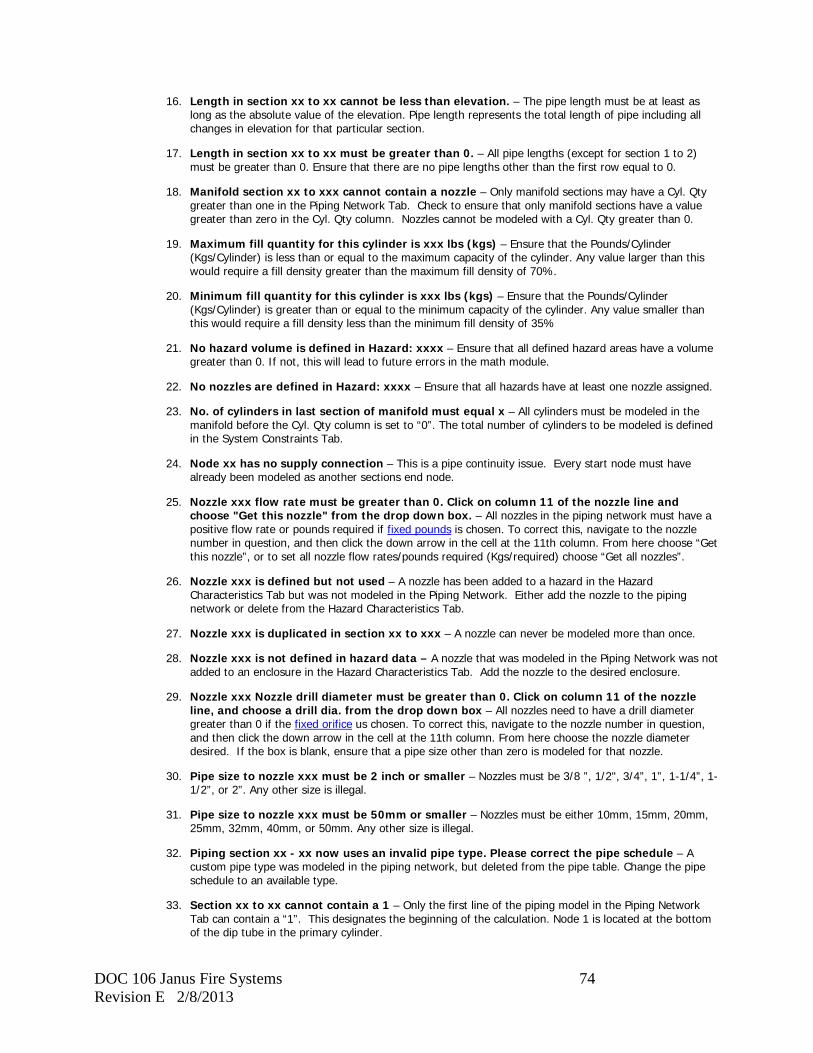
DOC 106 Janus Fire Systems 74 Revision E 2/8/2013
16. Length in section xx to xx cannot be less than elevation. – The pipe length must be at least as long as the absolute value of the elevation. Pipe length represents the total length of pipe including all changes in elevation for that particular section.
17. Length in section xx to xx must be greater than 0. – All pipe lengths (except for section 1 to 2) must be greater than 0. Ensure that there are no pipe lengths other than the first row equal to 0.
18. Manifold section xx to xxx cannot contain a nozzle – Only manifold sections may have a Cyl. Qty greater than one in the Piping Network Tab. Check to ensure that only manifold sections have a value greater than zero in the Cyl. Qty column. Nozzles cannot be modeled with a Cyl. Qty greater than 0.
19. Maximum fill quantity for this cylinder is xxx lbs (kgs) – Ensure that the Pounds/Cylinder (Kgs/Cylinder) is less than or equal to the maximum capacity of the cylinder. Any value larger than this would require a fill density greater than the maximum fill density of 70%.
20. Minimum fill quantity for this cylinder is xxx lbs (kgs) – Ensure that the Pounds/Cylinder (Kgs/Cylinder) is greater than or equal to the minimum capacity of the cylinder. Any value smaller than this would require a fill density less than the minimum fill density of 35%
21. No hazard volume is defined in Hazard: xxxx – Ensure that all defined hazard areas have a volume greater than 0. If not, this will lead to future errors in the math module.
22. No nozzles are defined in Hazard: xxxx – Ensure that all hazards have at least one nozzle assigned.
23. No. of cylinders in last section of manifold must equal x – All cylinders must be modeled in the manifold before the Cyl. Qty column is set to “0”. The total number of cylinders to be modeled is defined in the System Constraints Tab.
24. Node xx has no supply connection – This is a pipe continuity issue. Every start node must have already been modeled as another sections end node.
25. Nozzle xxx flow rate must be greater than 0. Click on column 11 of the nozzle line and choose "Get this nozzle" from the drop down box. – All nozzles in the piping network must have a positive flow rate or pounds required if fixed pounds is chosen. To correct this, navigate to the nozzle number in question, and then click the down arrow in the cell at the 11th column. From here choose “Get this nozzle”, or to set all nozzle flow rates/pounds required (Kgs/required) choose “Get all nozzles”.
26. Nozzle xxx is defined but not used – A nozzle has been added to a hazard in the Hazard Characteristics Tab but was not modeled in the Piping Network. Either add the nozzle to the piping network or delete from the Hazard Characteristics Tab.
27. Nozzle xxx is duplicated in section xx to xxx – A nozzle can never be modeled more than once.
28. Nozzle xxx is not defined in hazard data – A nozzle that was modeled in the Piping Network was not added to an enclosure in the Hazard Characteristics Tab. Add the nozzle to the desired enclosure.
29. Nozzle xxx Nozzle drill diameter must be greater than 0. Click on column 11 of the nozzle line, and choose a drill dia. from the drop down box – All nozzles need to have a drill diameter greater than 0 if the fixed orifice us chosen. To correct this, navigate to the nozzle number in question, and then click the down arrow in the cell at the 11th column. From here choose the nozzle diameter desired. If the box is blank, ensure that a pipe size other than zero is modeled for that nozzle.
30. Pipe size to nozzle xxx must be 2 inch or smaller – Nozzles must be 3/8 ”, 1/2", 3/4”, 1”, 1-1/4”, 1-1/2”, or 2”. Any other size is illegal.
31. Pipe size to nozzle xxx must be 50mm or smaller – Nozzles must be either 10mm, 15mm, 20mm, 25mm, 32mm, 40mm, or 50mm. Any other size is illegal.
32. Piping section xx - xx now uses an invalid pipe type. Please correct the pipe schedule – A custom pipe type was modeled in the piping network, but deleted from the pipe table. Change the pipe schedule to an available type.
33. Section xx to xx cannot contain a 1 – Only the first line of the piping model in the Piping Network Tab can contain a “1”. This designates the beginning of the calculation. Node 1 is located at the bottom of the dip tube in the primary cylinder.
DOC 106 Janus Fire Systems 75 Revision E 2/8/2013
34. Section xx to xx cannot contain a cylinder – After the manifold has been completed, no other cylinders can be joined to the system. Ensure that after the manifold, all other pipe sections have a “0” in the Cyl. Qty column.
35. Section xx to xx has no connecting branch with tee. Every thru tee needs a corresponding side, and every side tee needs a corresponding side OR thru. – If a tee is modeled, it must have a matching outlet.
36. Start node xx can end only one section – If a start node ends two sections of piping without a tee being modeled, then this error will appear. For instance, you cannot have a section 3 to 4 as well as a section 3 to 5 without modeling a tee at both section 3 to 4 AND section 3 to 5.
37. Start node xx can begin only two sections with tees. – A starting section cannot begin more than two tee sections. The start node must either begin two side outlet tees (a bull headed tee), or a side outlet and a thru outlet tee.
38. Start node xx cannot begin with two thru tees – For every thru tee, there must be a side tee. For every tee, there is an entry, a side outlet (change of direction), and a thru outlet (exiting the tee without changing direction). If there is nothing downstream of the tee except for a pressure release or a pressure trip, then see the Thru Tee Section.
39. Start node xx is duplicated in section xx to xx. Check the modeling of your tees. – A starting node cannot be repeated unless it is at the beginning of a tee. Check to make sure that the section in question begins two types of tees.
40. Total agent supplied is less than the total lbs/kgs required from the Piping Network Screen - Total pounds required to be discharged from piping network screen = xxxx – The amount of agent required to be discharged from the Piping Network (column 11) is greater than the total amount of gas being supplied from the System Constraints Tab. Either add additional gas to the cylinder, verify that the proper number of cylinders have been chosen, or decrease the amount of agent from each nozzle in the Piping Network Tab.
41. Total agent supplied is less than Total Weight Required - Total Weight required = xxxx – The total amount of agent required from the Hazard Characteristics Tab is greater than the total amount of gas being supplied from the System Constraints Tab. Either add additional gas to the cylinder, or verify that the proper number of cylinders have been chosen.
42. xx cylinders in pipe data does not match xx cylinders in system constraints – All main discharge cylinders must be modeled in the Piping Network Tab. After the manifold is complete, a Cyl. Qty of “0” should be entered in the Cyl. Qty column for all additional pipe sections.
DOC 106 Janus Fire Systems 76 Revision E 2/8/2013
Troubleshooting Calculation Errors
The following is a list of all possible error messages that may appear in the Error Messages / Design Notes Tab of the FM-200 Agent Design Form following the completion of a calculation.
Error: All discharge times xxx to 5 seconds have been used. Explanation: The program has attempted to successfully calculate the system starting with the discharge time requested in the System Constraints Tab. Discharge time MUST be between 5 to 10 seconds. Make sure pipe sizes have been optimized by referring to the minimum flow rate chart OR change the discharge time in the System Constraints Tab.
Error: Concentration achieved is less than requested for x. Explanation: This error was generated because one or more of the hazard areas did not achieve the concentration required. To fix this, ensure that all pipe and nozzle sizes are maximized going to the hazard area, or add agent to the storage cylinders. Adding agent to the cylinders is only recommended if there are no other errors generated.
Error: Cylinders Run Out of FM-200 Supply Before Steady State Flow is Achieved Explanation: Piping system is too long! Either decrease the amount of piping substantially, or add a substantial amount of agent to the system, i.e. add more cylinders.
Error: Cylinders Run Out of Liquid FM-200 Supply Before All Nozzles Begin Discharging Liquid Explanation: Piping system is too long! Either decrease the amount of piping substantially, or add a substantial amount of agent to the system, i.e. add more cylinders.
Error: Difference between longest and shortest end of liquid time is xx.xx seconds. The Ratio of this difference and system discharge time, xx.xx%, exceeds the limit of 50% Explanation: The maximum difference in end of liquid time must be less than 50% of the total discharge times. If the discharge time is 10 seconds, the difference between the closest nozzle finishing its liquid discharge and the farthest nozzle finishing its liquid discharge must be less than 5 seconds. To correct this, move the nozzles closer to each other.
Error: Difference between longest and shortest initial vapor times is x.xx seconds. The Ratio of this difference to the total discharge time, xx.xx%, exceeds the limit of 15% Explanation: The maximum difference in initial vapor times must be less than 15% of the total discharge time. If the discharge time is 10 sec, the difference between the closest nozzle's vapor time and the farthest nozzles vapor time must be less than 1.5 seconds. To correct this, move the nozzle with the shortest vapor time farther away from the nozzles.
Error: End of liquid discharge time is below the limit of 5 seconds. Explanation: The calculated discharge time is less than 5 seconds. Decrease the pipe size, increase the pipe length, or increase the desired discharge time in the System Constraints tab. Also if it is a system with fixed pipe and nozzles, decrease the drill diameter for each nozzle.
Error: End of liquid discharge time exceeds the limit of 10.0 seconds. Explanation: The calculated discharge time is more than 10 seconds. Increase the pipe size where applicable, decrease the pipe length, or decrease the desired discharge time in the System Constraints tab. Also if it is a system with fixed pipe and nozzles, increase the drill diameter for each nozzle.
Error: Error-cylinder fill density is greater than 70 Explanation: The maximum fill density is 70%. To correct this, remove agent from the cylinder(s).
Error: Error--Cylinder fill density is less than 35 lb/cu ft (560.65 kg/cubic meter) Explanation: The minimum fill density is 35%. To correct this, add agent to the cylinder(s).
Error: Flow for nozzle xxx fails to converge within xx.xxx%. Convergence to xx.xx%. Flow rate calculated xx.xx Flow rate theoretical xx.xx at xx.xx psig (x.xx bar). Explanation: The current system is modeled/designed in such a way where the program cannot calculate the system successfully. Try a different piping layout configuration.
Error: Flow split at Node xxx - xxx is xx.xx% which is above the maximum limit of 35% for a side tee. Explanation: The maximum flow out of a side tee is 35% of the incoming flow rate to that tee. i.e. if 10 lbs/sec is entering a side tee, then a maximum of 3.5 lbs/sec is allowed to discharge from the side outlet of that tee. This tee should be made a bull tee configuration.

DOC 106 Janus Fire Systems 77 Revision E 2/8/2013
Error: Flow split at Node xxx - xxx is xx.xx% which is below the minimum limit of 30% for a bull head tee. Explanation: The minimum flow out of a bull tee is 30% of the incoming flow rate to that tee. i.e. if 10 lbs/sec is entering a side tee, then a minimum of 3 lbs/sec has to discharge from either outlet of that tee. This tee should be made a side / thru tee configuration.
Error: Flow split at Node xxx - xxx is xx.xx% which is below the minimum limit of 10% for a side tee. Explanation: The minimum flow out of a side tee is 10% of the incoming flow rate to that tee. i.e. if 10 lbs/sec is entering a side tee, then a minimum of 1.0 lbs/sec has to discharge from the side outlet of that tee. The nozzles fed from this tee need to have additional weight added to them via the last column of the piping model.
Error: Insufficient agent in storage to produce requested amount discharged per nozzle. Explanation: More agent is required in the cylinder to deliver the amount of gas required at the nozzles. Add more FM-200 to the cylinder(s).
Error: Nozzle xxx ratio of orifice to pipe area is xx.xx%. This exceeds the limit of 85% Explanation: The total orifice area of the nozzle is more than 85% of the feed pipe area. Increase the pipe size feeding the nozzle, or increase the desired discharge time in the System Constraints tab. If pipe size is maximized, you can also add another nozzle.
Error: Nozzle xxx ratio of orifice to pipe area is xx.xx%. This is below the limit of 10%. Explanation: The total orifice area of the nozzle is less than 10% of the feed pipe area. Decrease the pipe size feeding the nozzle, or decrease the desired discharge time in the System Constraints tab.
Error: Orifice diameter required for nozzle xxx is x.xxxx. This is larger than x.xxxx, which is the biggest available drill. Explanation: The flow rate is too high. Increase the discharge time OR increase the pipe size OR add additional nozzles.
Error: Orifice diameter required for nozzle xxx is x.xxxx. This is smaller than x.xxxx, which is the smallest available drill. Explanation: The flow rate is too low. Decrease the discharge time OR decrease the pipe size OR decrease the quantity of nozzles.
Error: Percent agent in pipe is xx.xx% This exceeds the maximum permitted value of 80%. Explanation: The volume of pipe must somehow be decreased in order to correct this. Decrease pipe length OR decrease pipe size OR increase agent quantity. At any given moment, only 80% of the total storage contents can be in the piping at one time.
Error: PIPING SYSTEM IS TOO LONG, PIPE SIZES TOO SMALL OR NOZZLE SIZES TOO LARGE REDESIGN SYSTEM - FURTHER CALCULATION USING THIS DATA WILL NOT PRODUCE AN ACCEPTABLE ANSWER Explanation: The current system is modeled/designed in such a way where the program cannot calculate the system successfully. Try a different piping layout configuration.
Error: Pressure in section xx - xx drops below 80 psig (5.516 bar) Explanation: The minimum nozzle pressure dropped below 80 psig (5.516 bar). To fix this, maximize pipe sizes, increase the discharge time (make it longer), or decrease pipe lengths (i.e. move the cylinder closer to the hazard).
Error: Pressure in system is below minimum permitted pressure of 80 psig (5.516 bar). Explanation: The minimum nozzle pressure dropped below 5.516 bar. To fix this, maximize pipe sizes, increase the discharge time, or decrease pipe lengths (i.e. move the cylinder closer to the hazard).
Error: System fails to converge within 1.25%. System may be too long. Explanation: The current system is modeled/designed in such a way where the program cannot calculate the system successfully. Try a different piping layout configuration.
Error: This Selector valve has a manifold dead leg downstream of its take-off with a total pipe volume of XXX cu.ft (cu.M). The dead leg pipe volume (cu.ft./cu.M) to agent (lbs/kg) limit is: 0.00332857 cu.ft/lb (0.000208 cu.M/kg). Explanation: There is too much pipe volume in the dead leg. To fix this, either move this valve closer to the end of the selector valve manifold, decrease the pipe size of the selector valve manifold, OR add agent to the cylinder.
Error: Valve for section xx - xx is not available. Explanation: Valves are only available in 1/2", 1", 1-1/2", 2", 3", 4" and 6" (15, 25, 40, 50, 80, 100 & 150 mm). Fix this section of pipe to one of these sizes OR decrease the discharge time in an effort to increase the flow rate.

DOC 106 Janus Fire Systems 78 Revision E 2/8/2013
Error: Vapor time at nozzle xxx is xxx sec. Ratio of longest initial vapor time to discharge time, xx.xx%, exceeds limit of 20% Explanation: The maximum initial vapor time at any nozzle must be less than 20% of the total discharge time. If the discharge time is 10 sec, the maximum initial vapor time at any nozzle must be less than 2.0 seconds. To correct this, decrease pipe lengths.
Error: Warning: Flow in Section xxx - xxx is below permitted minimum of lbs/sec (kg/sec). Explanation: The pipeline flow rate must be greater than those shown in the red column of the minimum flow rates chart. For instance, if 1" pipe is chosen, then the flow rate must be at least 3.64 lbs/sec. To fix this either decrease the pipe size or decrease the discharge time in the System Constraints tab. NOTE – If this section contains a nozzle and you get this error message then: The pipeline flow rate at a nozzle must be greater than those shown in the blue column of the minimum flow rates chart. For instance, if a 1" nozzle is chosen, then the flow rate must be at least 2.18 lbs/sec. To fix this either decrease the pipe size or decrease the discharge time in the System Constraints tab.
Design Notes
The following are all the possible design notes that may appear in the Error Messages / Design Notes Tab of the FM-200 Agent Design Form following the completion of a calculation. These notes are for informational purposes only. No user action is required.
Note: Hydraulic calculation was successful. Explanation: This note appears when a calculation produces no errors.
Note: Version dated xxxx Explanation: This note lists the version of the Janus Design Suite used to perform calculations.
Note: All agent requirements were calculated based on NFPA 2001, Table A.5.5.1(k) Explanation: This note appears for calculations performed using U.S. Standard measurements.
Note: All agent requirements were calculated based on NFPA 2001, Table A.5.5.1(i) Explanation: This note appears for calculations performed using Metric measurements.
Note: Pipe Sizes & Nozzle Diameters are fixed. Explanation: This note appears for calculations performed using the fixed orifice option.
Note: Maximum Temperature that enclosure x can have and still be below the NOAEL is: x Explanation: This denotes the highest temperature at which point the concentration of FM-200 will be above the NOAEL level.
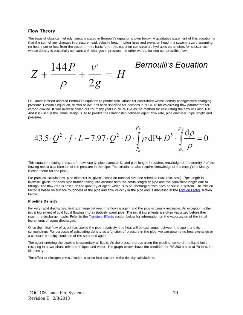
DOC 106 Janus Fire Systems 79 Revision E 2/8/2013
Flow Theory
The basis of classical hydrodynamics is stated in Bernoulli’s equation shown below. A qualitative statement of this equation is that the sum of any changes in pressure head, velocity head, friction head and elevation head in a system is zero assuming no heat input or loss from the system. In its basic form, this equation can calculate hydraulic parameters for substances whose density is essentially constant with changes in pressure—in other words, for non-compressible flow.
Dr. James Hesson adapted Bernoulli’s equation to permit calculations for substances whose density changes with changing pressure. Hesson’s equation, shown below, has been specified for decades in NFPA 12 for calculating flow parameters for carbon dioxide. It was likewise called out for many years in NFPA 12A as the method for calculating the flow of Halon 1301. And it is used in the Janus Design Suite to predict the relationship between agent flow rate, pipe diameter, pipe length and pressure.
This equation relating pressure P, flow rate Q, pipe diameter D, and pipe length L requires knowledge of the density ? of the flowing media as a function of the pressure in the pipe. The calculation also requires knowledge of the term f (the Moody friction factor for the pipe).
For practical calculations, pipe diameter is "given" based on nominal size and schedule (wall thickness). Pipe length is likewise "given" for each pipe branch taking into account both the actual length of pipe and the equivalent length due to fittings. The flow rate is based on the quantity of agent which is to be discharged from each nozzle in a system. The friction factor is based on surface roughness of the pipe and flow velocity in the pipe and is discussed in the Friction Factor section below.
Pipeline Density
For very rapid discharges, heat exchange between the flowing agent and the pipe is usually negligible. An exception is the initial increment of cold liquid flowing into a relatively warm pipe. The initial increments are often vaporized before they reach the discharge nozzle. Refer to the Transient Effects section below for information on the vaporization of the initial increments of agent discharged.
Once the initial flow of agent has cooled the pipe, relatively little heat will be exchanged between the agent and its surroundings. For purposes of calculating density as a function of pressure in the pipe, we can assume no heat exchange or a constant enthalpy condition of the saturated agent.
The agent entering the pipeline is essentially all liquid. As the pressure drops along the pipeline, some of the liquid boils resulting in a two-phase mixture of liquid and vapor. The graph below shows the condition for FM-200 stored at 70 lb/cu ft fill density.
The effect of nitrogen pressurization is taken into account in the density calculations.
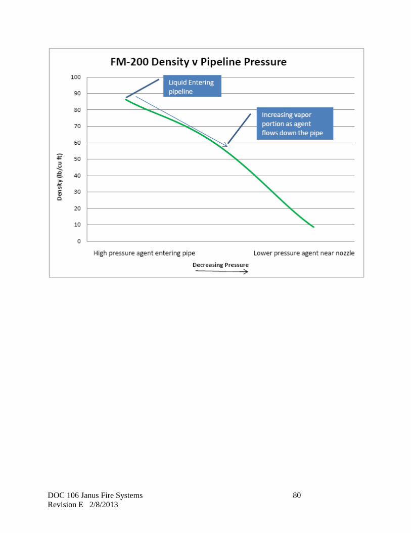
DOC 106 Janus Fire Systems 80 Revision E 2/8/2013

DOC 106 Janus Fire Systems 81 Revision E 2/8/2013
Friction Factor
The graph below shows the Moody friction factor f for clean steel pipe.
The friction factor varies considerably for lower Reynolds numbers. As the Reynolds number increases, however, the friction factor becomes constant. The flow regime for which the friction factor is constant is called turbulent flow.
The minimum flow rate permitted in the Janus Design Suite is that flow which produces turbulent flow and hence a "constant" friction factor. Flow in the turbulent range simplifies the calculation by "fixing" the friction factor at a known value. Flow in the turbulent range also produces a relatively uniform mixture of the liquid and vapor phases within the pipe. This is useful in handling the phenomena of mechanical separation of the liquid and vapor phases which has been observed when the flow is split at tee junctions.
Reynolds number is related to flow velocity and viscosity of the flowing media.
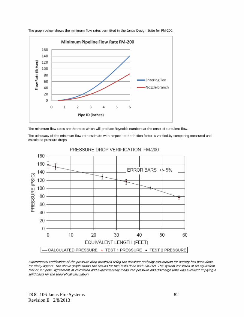
DOC 106 Janus Fire Systems 82 Revision E 2/8/2013
The graph below shows the minimum flow rates permitted in the Janus Design Suite for FM-200.
The minimum flow rates are the rates which will produce Reynolds numbers at the onset of turbulent flow.
The adequacy of the minimum flow rate estimate with respect to the friction factor is verified by comparing measured and calculated pressure drops.
Experimental verification of the pressure drop predicted using the constant enthalpy assumption for density has been done for many agents. The above graph shows the results for two tests done with FM-200. The system consisted of 60 equivalent feet of ½" pipe. Agreement of calculated and experimentally measured pressure and discharge time was excellent implying a solid basis for the theoretical calculation.
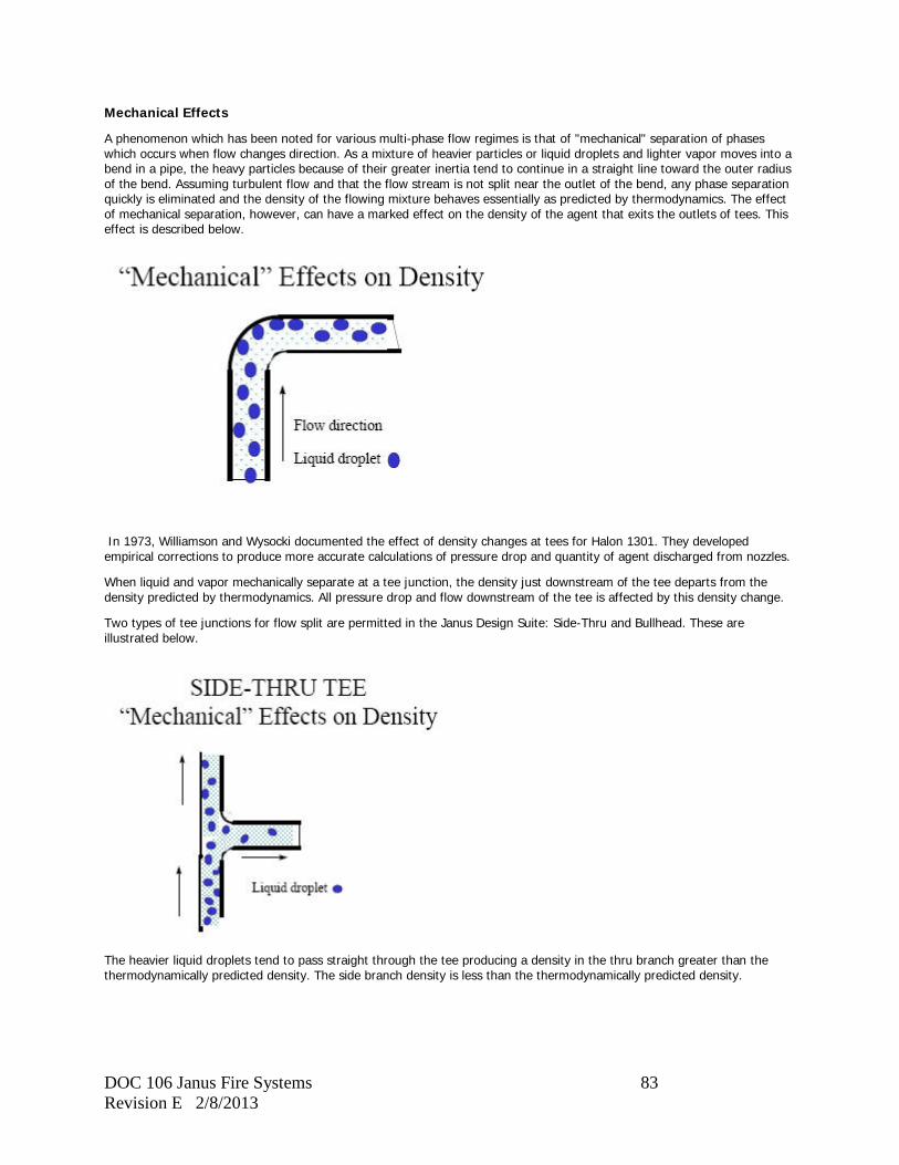
DOC 106 Janus Fire Systems 83 Revision E 2/8/2013
Mechanical Effects
A phenomenon which has been noted for various multi-phase flow regimes is that of "mechanical" separation of phases which occurs when flow changes direction. As a mixture of heavier particles or liquid droplets and lighter vapor moves into a bend in a pipe, the heavy particles because of their greater inertia tend to continue in a straight line toward the outer radius of the bend. Assuming turbulent flow and that the flow stream is not split near the outlet of the bend, any phase separation quickly is eliminated and the density of the flowing mixture behaves essentially as predicted by thermodynamics. The effect of mechanical separation, however, can have a marked effect on the density of the agent that exits the outlets of tees. This effect is described below.
In 1973, Williamson and Wysocki documented the effect of density changes at tees for Halon 1301. They developed empirical corrections to produce more accurate calculations of pressure drop and quantity of agent discharged from nozzles.
When liquid and vapor mechanically separate at a tee junction, the density just downstream of the tee departs from the density predicted by thermodynamics. All pressure drop and flow downstream of the tee is affected by this density change.
Two types of tee junctions for flow split are permitted in the Janus Design Suite: Side-Thru and Bullhead. These are illustrated below.
The heavier liquid droplets tend to pass straight through the tee producing a density in the thru branch greater than the thermodynamically predicted density. The side branch density is less than the thermodynamically predicted density.
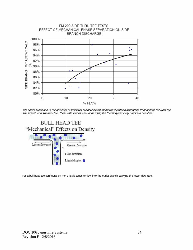
DOC 106 Janus Fire Systems 84 Revision E 2/8/2013
The above graph shows the deviation of predicted quantities from measured quantities discharged from nozzles fed from the side branch of a side-thru tee. These calculations were done using the thermodynamically predicted densities.
For a bull head tee configuration more liquid tends to flow into the outlet branch carrying the lesser flow rate.
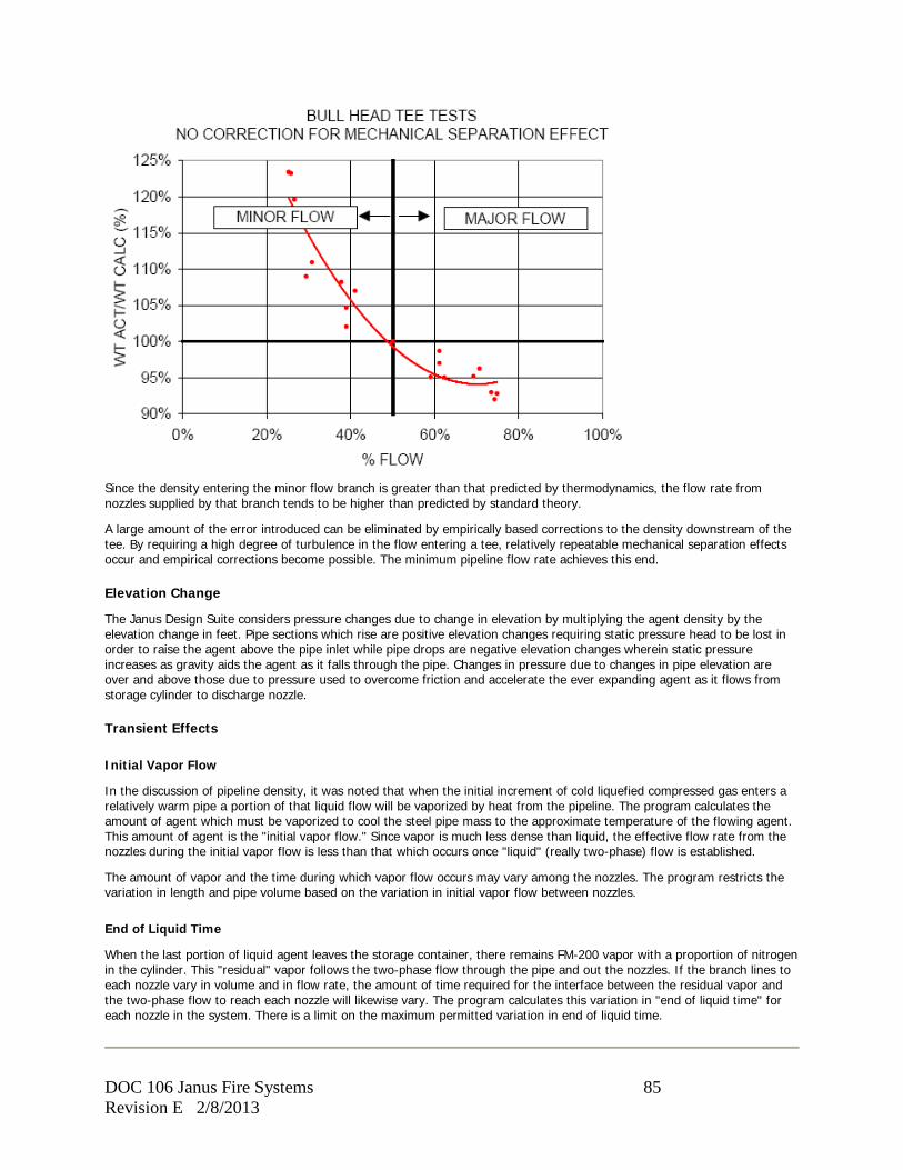
DOC 106 Janus Fire Systems 85 Revision E 2/8/2013
Since the density entering the minor flow branch is greater than that predicted by thermodynamics, the flow rate from nozzles supplied by that branch tends to be higher than predicted by standard theory.
A large amount of the error introduced can be eliminated by empirically based corrections to the density downstream of the tee. By requiring a high degree of turbulence in the flow entering a tee, relatively repeatable mechanical separation effects occur and empirical corrections become possible. The minimum pipeline flow rate achieves this end.
Elevation Change
The Janus Design Suite considers pressure changes due to change in elevation by multiplying the agent density by the elevation change in feet. Pipe sections which rise are positive elevation changes requiring static pressure head to be lost in order to raise the agent above the pipe inlet while pipe drops are negative elevation changes wherein static pressure increases as gravity aids the agent as it falls through the pipe. Changes in pressure due to changes in pipe elevation are over and above those due to pressure used to overcome friction and accelerate the ever expanding agent as it flows from storage cylinder to discharge nozzle.
Transient Effects
Initial Vapor Flow
In the discussion of pipeline density, it was noted that when the initial increment of cold liquefied compressed gas enters a relatively warm pipe a portion of that liquid flow will be vaporized by heat from the pipeline. The program calculates the amount of agent which must be vaporized to cool the steel pipe mass to the approximate temperature of the flowing agent. This amount of agent is the "initial vapor flow." Since vapor is much less dense than liquid, the effective flow rate from the nozzles during the initial vapor flow is less than that which occurs once "liquid" (really two-phase) flow is established.
The amount of vapor and the time during which vapor flow occurs may vary among the nozzles. The program restricts the variation in length and pipe volume based on the variation in initial vapor flow between nozzles.
End of Liquid Time
When the last portion of liquid agent leaves the storage container, there remains FM-200 vapor with a proportion of nitrogen in the cylinder. This "residual" vapor follows the two-phase flow through the pipe and out the nozzles. If the branch lines to each nozzle vary in volume and in flow rate, the amount of time required for the interface between the residual vapor and the two-phase flow to reach each nozzle will likewise vary. The program calculates this variation in "end of liquid time" for each nozzle in the system. There is a limit on the maximum permitted variation in end of liquid time.
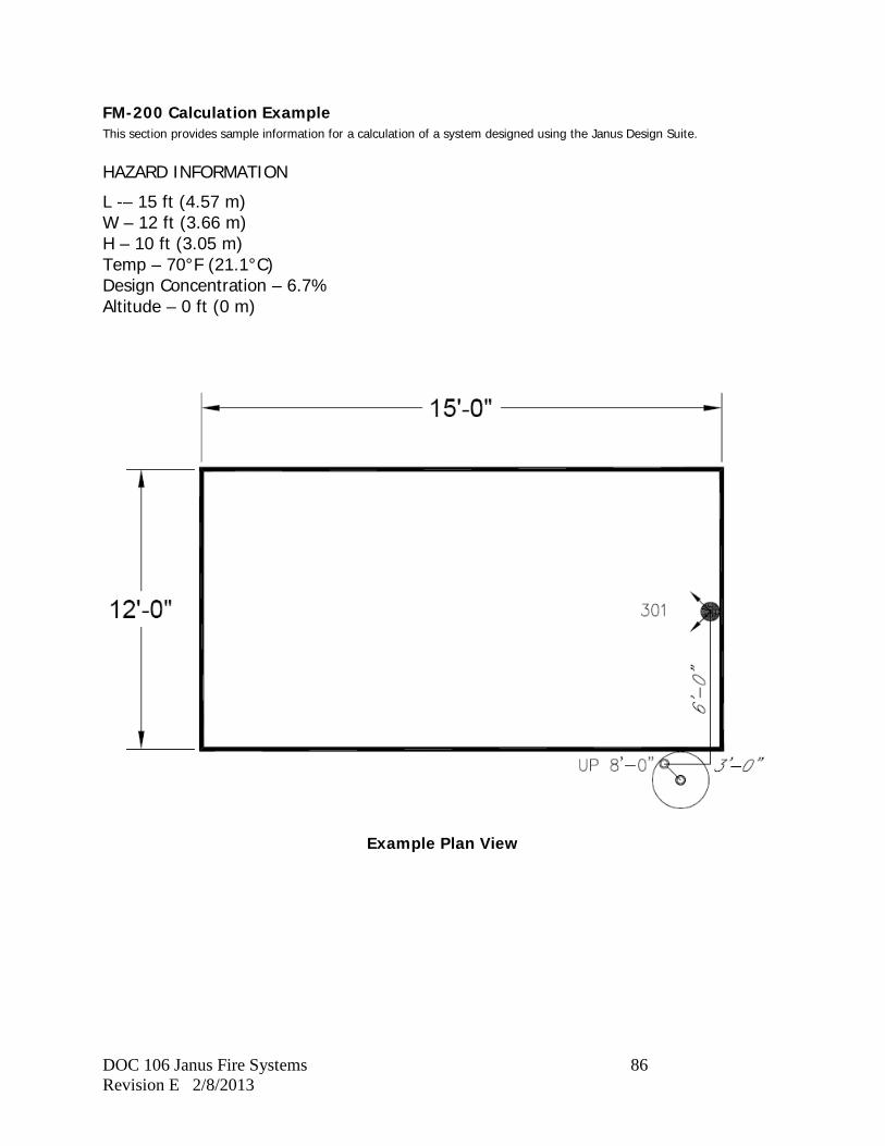
DOC 106 Janus Fire Systems 86 Revision E 2/8/2013
FM-200 Calculation Example This section provides sample information for a calculation of a system designed using the Janus Design Suite. HAZARD INFORMATION
L -– 15 ft (4.57 m) W – 12 ft (3.66 m) H – 10 ft (3.05 m) Temp – 70°F (21.1°C) Design Concentration – 6.7% Altitude – 0 ft (0 m)
Example Plan View
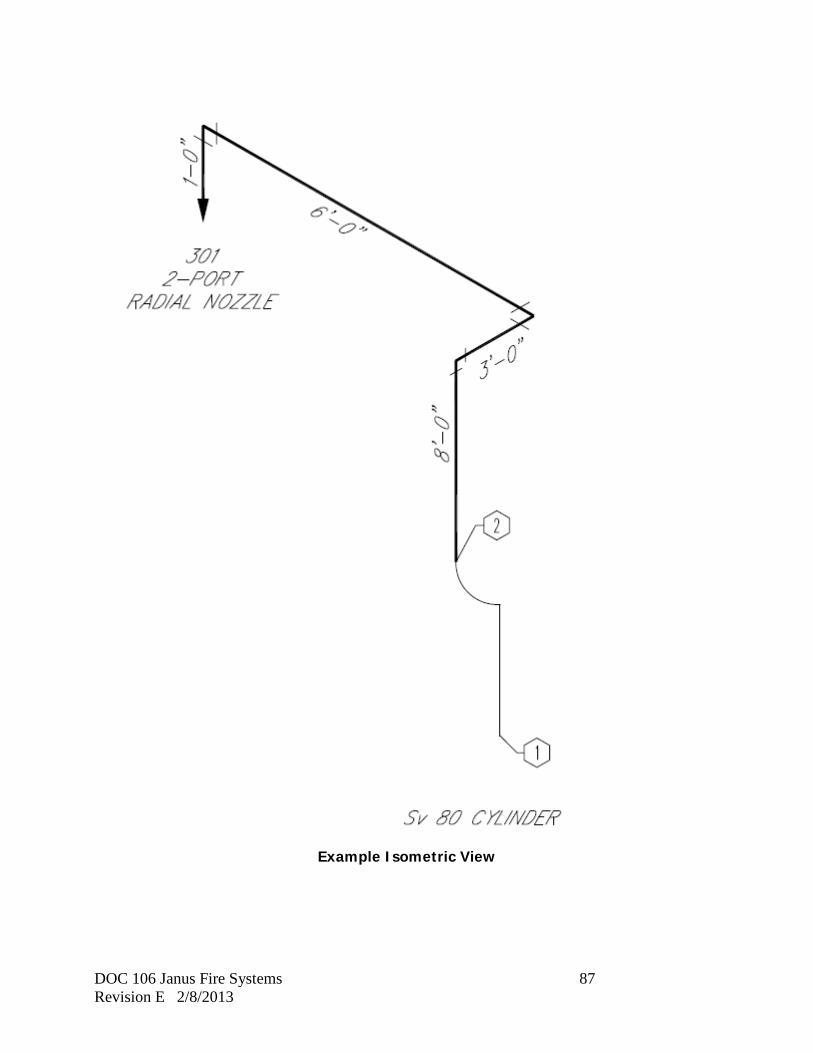
DOC 106 Janus Fire Systems 87 Revision E 2/8/2013
Example Isometric View
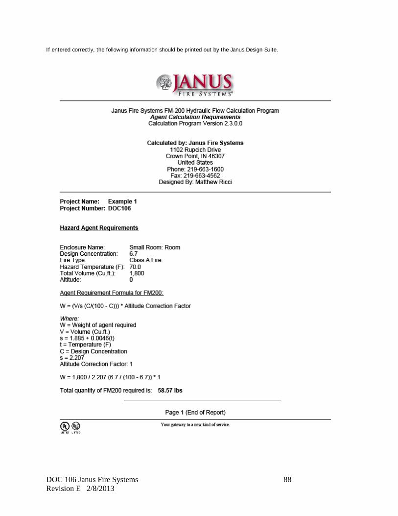
DOC 106 Janus Fire Systems 88 Revision E 2/8/2013
If entered correctly, the following information should be printed out by the Janus Design Suite.

DOC 106 Janus Fire Systems 89 Revision E 2/8/2013
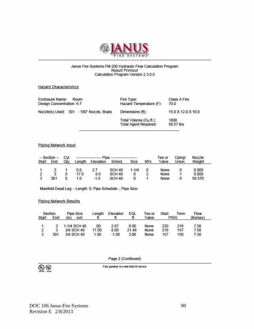
DOC 106 Janus Fire Systems 90 Revision E 2/8/2013
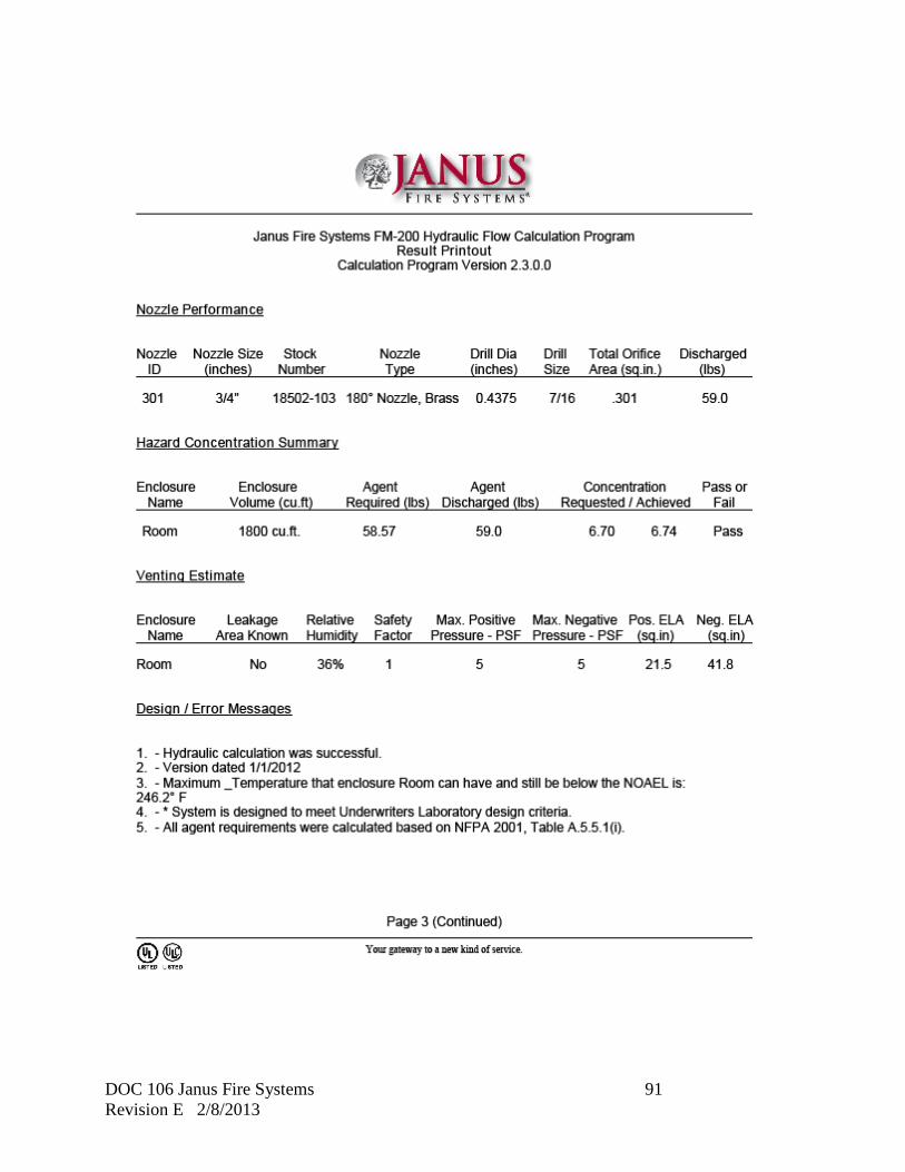
DOC 106 Janus Fire Systems 91 Revision E 2/8/2013

DOC 106 Janus Fire Systems 92 Revision E 2/8/2013
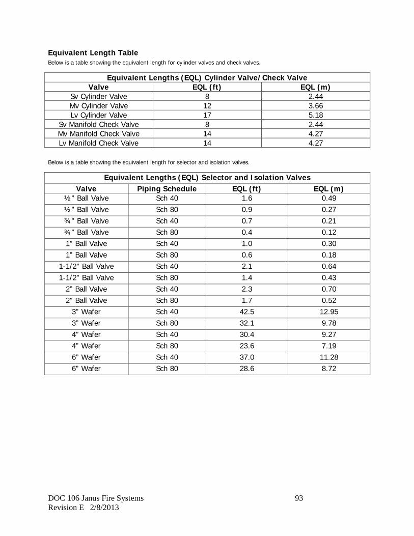
DOC 106 Janus Fire Systems 93 Revision E 2/8/2013
Equivalent Length Table Below is a table showing the equivalent length for cylinder valves and check valves.
Equivalent Lengths (EQL) Cylinder Valve/Check Valve Valve EQL (ft) EQL (m)
Sv Cylinder Valve 8 2.44 Mv Cylinder Valve 12 3.66 Lv Cylinder Valve 17 5.18
Sv Manifold Check Valve 8 2.44 Mv Manifold Check Valve 14 4.27 Lv Manifold Check Valve 14 4.27
Below is a table showing the equivalent length for selector and isolation valves.
Equivalent Lengths (EQL) Selector and Isolation Valves Valve Piping Schedule EQL (ft) EQL (m)
½” Ball Valve Sch 40 1.6 0.49 ½” Ball Valve Sch 80 0.9 0.27 ¾” Ball Valve Sch 40 0.7 0.21 ¾” Ball Valve Sch 80 0.4 0.12 1” Ball Valve Sch 40 1.0 0.30 1” Ball Valve Sch 80 0.6 0.18
1-1/2” Ball Valve Sch 40 2.1 0.64 1-1/2” Ball Valve Sch 80 1.4 0.43
2” Ball Valve Sch 40 2.3 0.70 2” Ball Valve Sch 80 1.7 0.52
3” Wafer Sch 40 42.5 12.95 3” Wafer Sch 80 32.1 9.78 4” Wafer Sch 40 30.4 9.27 4” Wafer Sch 80 23.6 7.19 6” Wafer Sch 40 37.0 11.28 6” Wafer Sch 80 28.6 8.72
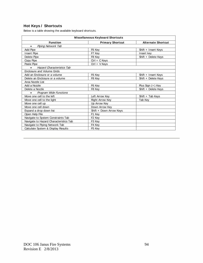
DOC 106 Janus Fire Systems 94 Revision E 2/8/2013
Hot Keys / Shortcuts
Below is a table showing the available keyboard shortcuts.
Miscellaneous Keyboard Shortcuts Function Primary Shortcut Alternate Shortcut
• Piping Network Tab Add Pipe F6 Key Shift + Insert Keys Insert Pipe F7 Key Insert key Delete Pipe F8 Key Shift + Delete Keys Copy Pipe Ctrl + C Keys Paste Pipe Ctrl + V Keys
• Hazard Characteristics Tab Enclosure and Volume Grids Add an Enclosure or a volume F6 Key Shift + Insert Keys Delete an Enclosure or a volume F8 Key Shift + Delete Keys Area Nozzle List Add a Nozzle F6 Key Plus Sign (+) Key Delete a Nozzle F8 Key Shift + Delete Keys
• Program Wide Functions Move one cell to the left Left Arrow Key Shift + Tab Keys Move one cell to the light Right Arrow Key Tab Key Move one cell up Up Arrow Key Move one cell down Down Arrow Key Expand a drop down list Shift + Down Arrow Keys Open Help File F1 Key Navigate to System Constraints Tab F2 Key Navigate to Hazard Characteristics Tab F3 Key Navigate to Piping Network Tab F4 Key Calculate System & Display Results F5 Key
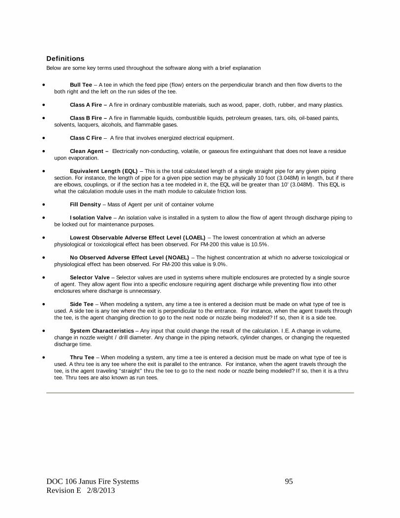
DOC 106 Janus Fire Systems 95 Revision E 2/8/2013
Definitions Below are some key terms used throughout the software along with a brief explanation
• Bull Tee – A tee in which the feed pipe (flow) enters on the perpendicular branch and then flow diverts to the both right and the left on the run sides of the tee.
• Class A Fire – A fire in ordinary combustible materials, such as wood, paper, cloth, rubber, and many plastics.
• Class B Fire – A fire in flammable liquids, combustible liquids, petroleum greases, tars, oils, oil-based paints, solvents, lacquers, alcohols, and flammable gases.
• Class C Fire – A fire that involves energized electrical equipment.
• Clean Agent – Electrically non-conducting, volatile, or gaseous fire extinguishant that does not leave a residue upon evaporation.
• Equivalent Length (EQL) – This is the total calculated length of a single straight pipe for any given piping section. For instance, the length of pipe for a given pipe section may be physically 10 foot (3.048M) in length, but if there are elbows, couplings, or if the section has a tee modeled in it, the EQL will be greater than 10’ (3.048M). This EQL is what the calculation module uses in the math module to calculate friction loss.
• Fill Density – Mass of Agent per unit of container volume
• Isolation Valve – An isolation valve is installed in a system to allow the flow of agent through discharge piping to be locked out for maintenance purposes.
• Lowest Observable Adverse Effect Level (LOAEL) – The lowest concentration at which an adverse physiological or toxicological effect has been observed. For FM-200 this value is 10.5%.
• No Observed Adverse Effect Level (NOAEL) – The highest concentration at which no adverse toxicological or physiological effect has been observed. For FM-200 this value is 9.0%.
• Selector Valve – Selector valves are used in systems where multiple enclosures are protected by a single source of agent. They allow agent flow into a specific enclosure requiring agent discharge while preventing flow into other enclosures where discharge is unnecessary.
• Side Tee – When modeling a system, any time a tee is entered a decision must be made on what type of tee is used. A side tee is any tee where the exit is perpendicular to the entrance. For instance, when the agent travels through the tee, is the agent changing direction to go to the next node or nozzle being modeled? If so, then it is a side tee.
• System Characteristics – Any input that could change the result of the calculation. I.E. A change in volume, change in nozzle weight / drill diameter. Any change in the piping network, cylinder changes, or changing the requested discharge time.
• Thru Tee – When modeling a system, any time a tee is entered a decision must be made on what type of tee is used. A thru tee is any tee where the exit is parallel to the entrance. For instance, when the agent travels through the tee, is the agent traveling “straight” thru the tee to go to the next node or nozzle being modeled? If so, then it is a thru tee. Thru tees are also known as run tees.

DOC 106 Janus Fire Systems 96 Revision E 2/8/2013
Copyright The copyright and intellectual property rights of this software, Janus Design Suite, and all its documentation, including the online help system, are owned by Janus Fire Systems, and are protected by copyright laws and international intellectual property right treaties. You may not copy any portion of the software or documentation in any form, except to use this software in accordance with the terms of the agreement or to make one copy for backup purposes. You may not alter the software in any way. If copies of the documentation must be made, you should make them in printed form only.

DOC 106 Janus Fire Systems 97 Revision E 2/8/2013
Blank