jea bradley 30p schematic process calcs
TRANSCRIPT
Final Report of Geotechnical Exploration For
JEA Bradley Road Pump Station 10477 Bradley Road Jacksonville, Florida
MAE Project No. 0011-0011
September 9, 2015
Prepared for:
Prepared by:
8936 Western Way, Suite 12 Jacksonville, Florida 32256
Phone (904) 519-6990 Fax (904) 519-6992
8936 Western Way, Suite 12 Jacksonville, Florida 32256 Phone: (904)519-6990 Fax: (904)519-6992
September 9, 2015
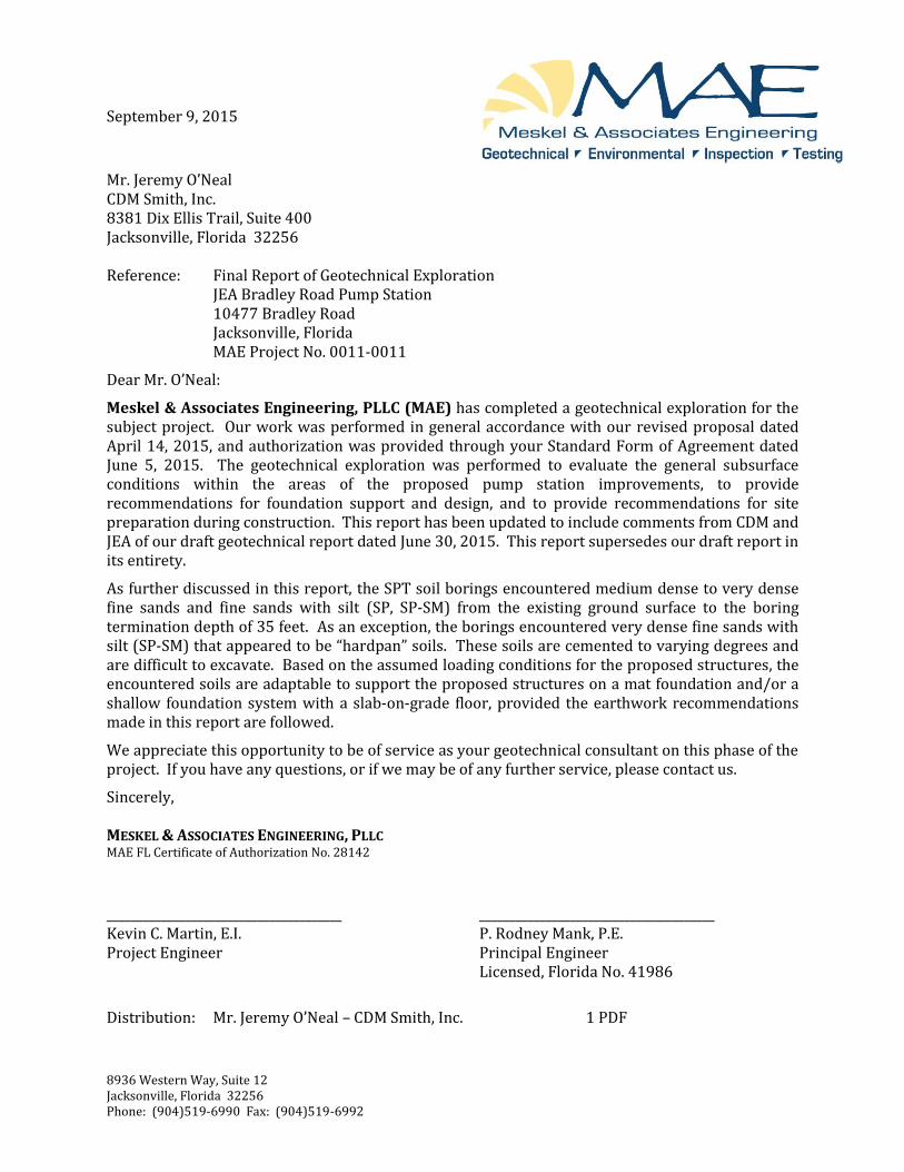
Mr. Jeremy O’Neal CDM Smith, Inc. 8381 Dix Ellis Trail, Suite 400 Jacksonville, Florida 32256 Reference: Final Report of Geotechnical Exploration
JEA Bradley Road Pump Station 10477 Bradley Road Jacksonville, Florida MAE Project No. 0011-0011
Dear Mr. O’Neal:
Meskel & Associates Engineering, PLLC (MAE) has completed a geotechnical exploration for the subject project. Our work was performed in general accordance with our revised proposal dated April 14, 2015, and authorization was provided through your Standard Form of Agreement dated June 5, 2015. The geotechnical exploration was performed to evaluate the general subsurface conditions within the areas of the proposed pump station improvements, to provide recommendations for foundation support and design, and to provide recommendations for site preparation during construction. This report has been updated to include comments from CDM and JEA of our draft geotechnical report dated June 30, 2015. This report supersedes our draft report in its entirety.
As further discussed in this report, the SPT soil borings encountered medium dense to very dense fine sands and fine sands with silt (SP, SP-SM) from the existing ground surface to the boring termination depth of 35 feet. As an exception, the borings encountered very dense fine sands with silt (SP-SM) that appeared to be “hardpan” soils. These soils are cemented to varying degrees and are difficult to excavate. Based on the assumed loading conditions for the proposed structures, the encountered soils are adaptable to support the proposed structures on a mat foundation and/or a shallow foundation system with a slab-on-grade floor, provided the earthwork recommendations made in this report are followed.
We appreciate this opportunity to be of service as your geotechnical consultant on this phase of the project. If you have any questions, or if we may be of any further service, please contact us.
Sincerely, MESKEL & ASSOCIATES ENGINEERING, PLLC MAE FL Certificate of Authorization No. 28142
_______________________________________ _______________________________________ Kevin C. Martin, E.I. P. Rodney Mank, P.E. Project Engineer Principal Engineer Licensed, Florida No. 41986
Distribution: Mr. Jeremy O’Neal – CDM Smith, Inc. 1 PDF
JEA Bradley Road Pump Station MAE Final Report No. 0011-0011
8936 Western Way, Suite 12 Jacksonville, Florida 32256
Phone: (904)519-6990 Fax: (904)519-6992
Page | i
TABLE OF CONTENTS
Subject Page No. 1.0 PROJECT INFORMATION ................................................................................................................ 1
1.1 General ............................................................................................................................................................. 1
1.2 Project Description ..................................................................................................................................... 1
1.3 Site Conditions .............................................................................................................................................. 1
2.0 FIELD EXPLORATION ...................................................................................................................... 1
2.1 SPT Borings .................................................................................................................................................... 2
2.2 Double Ring Infiltrometer (DRI) Tests ............................................................................................... 2
3.0 LABORATORY TESTING .................................................................................................................. 2
4.0 GENERAL SUBSURFACE CONDITIONS ........................................................................................ 2
4.1 General Soil Profile ..................................................................................................................................... 2
4.2 Groundwater Level ..................................................................................................................................... 3
4.3 USDA Soil Survey Data ............................................................................................................................... 3
4.4 Seasonal High Groundwater Level ....................................................................................................... 4
5.0 DESIGN RECOMMENDATIONS ...................................................................................................... 4
5.1 General ............................................................................................................................................................. 4
5.2 Foundation Design Recommendations............................................................................................... 4
5.3 Stormwater Management ........................................................................................................................ 6
6.0 SITE PREPARATION AND EARTHWORK RECOMMENDATIONS ........................................ 6
6.1 Clearing and Stripping ............................................................................................................................... 6
6.2 Temporary Groundwater Control ........................................................................................................ 6
6.3 Compaction .................................................................................................................................................... 7
6.4 Structural Backfill and Fill Soils............................................................................................................. 7
6.5 Foundation Areas ........................................................................................................................................ 7
7.0 QUALITY CONTROL TESTING ....................................................................................................... 8
8.0 REPORT LIMITATIONS .................................................................................................................... 8
JEA Bradley Road Pump Station MAE Final Report No. 0011-0011
8936 Western Way, Suite 12 Jacksonville, Florida 32256
Phone: (904)519-6990 Fax: (904)519-6992
Page | ii
FIGURES
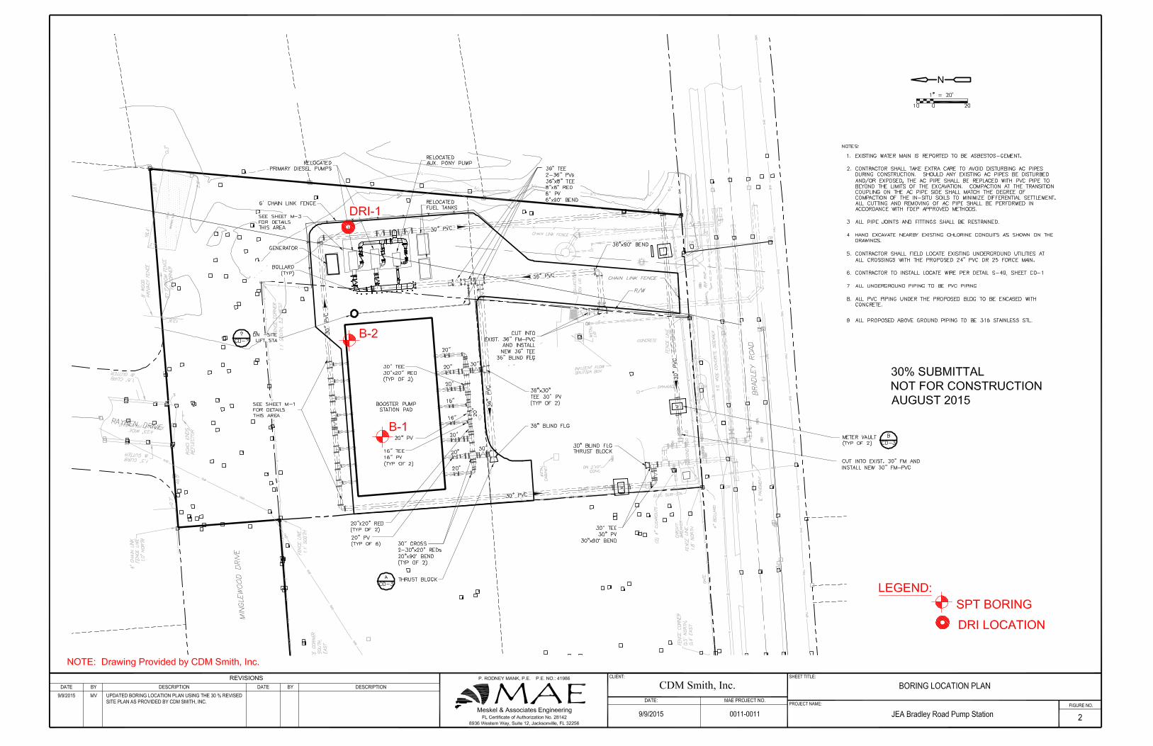
Figure 1. Site Location Plan
Figure 2. Boring Location Plan
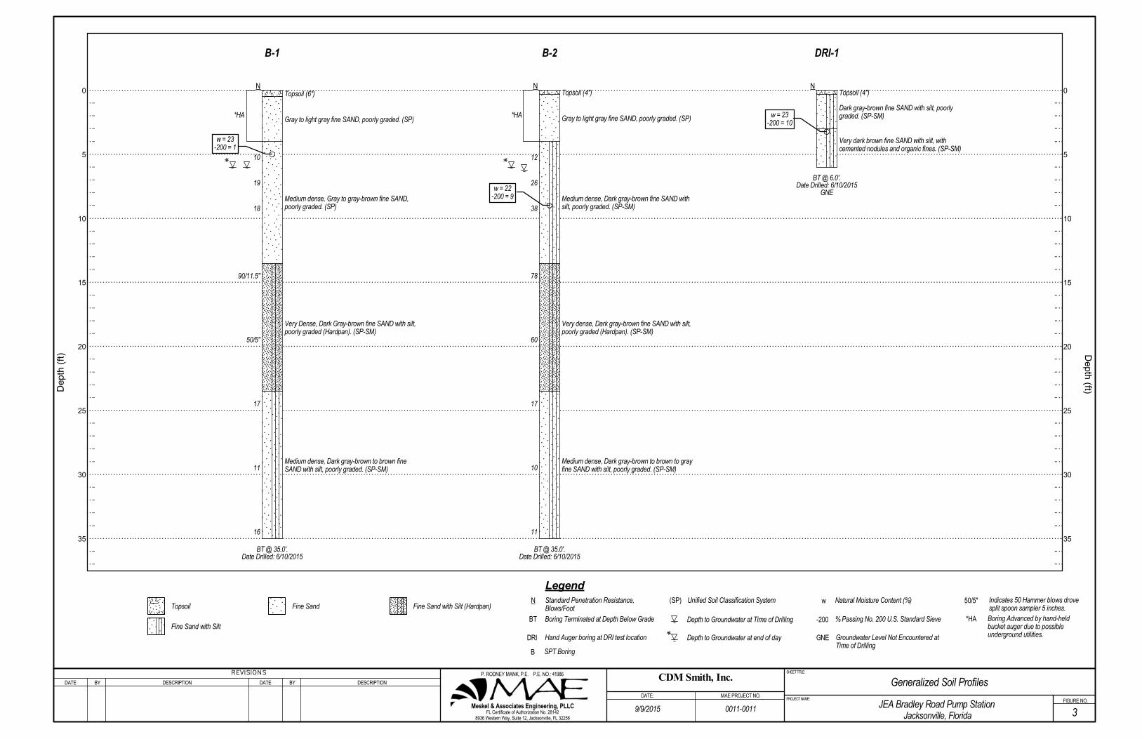
Figure 3. Generalized Soil Profiles
APPENDICES
Appendix A. Soil Boring Logs
Field Exploration Procedures
Key to Boring Logs
Key to Soil Classification
Appendix B. Laboratory Data
Laboratory Test Procedures
Appendix C. DRI Test Results
DRI Test Procedures
JEA Bradley Road Pump Station MAE Report No. 0011-0011
8936 Western Way, Suite 12 Jacksonville, Florida 32256
Phone: (904)519-6990 Fax: (904)519-6992
Page | 1
1.0 PROJECT INFORMATION
1.1 General
Project information was provided to us by Mr. Jeremy O’Neal, with CDM Smith, Inc. (CDM) during preparation of the field exploration program. We were provided with a pdf site plan (CDM Figure No. 3-12) prepared by CDM, undated, that showed the proposed site improvements and existing features on-site. An updated version of the site plan, dated August 2015, was used for this final report to show the field work locations relative to the 30 Percent submittal project layout.
1.2 Project Description
The site for the subject project is located at 10477 Bradley Road in Duval County, Florida. The site is located on the north side of Bradley Road, one block west of St. Johns Bluff Road, in Jacksonville, Florida. The general site location is shown on Figure 1.
Based on the provided information and our discussions, it is our understanding the proposed site improvements will include construction of a grade-supported pump pad and a single-story electrical building. We have assumed the pump pad will be constructed as a rigid mat foundation, and the proposed electrical building to be constructed on a shallow foundation system and slab-on-grade floor. Also, we have assumed that site grading will include up to one foot of fill within the structure areas.
Although detailed information has not been provided, we have assumed the mat foundation for the pump pad will have maximum loads of 1,000 pounds per square foot or less. We have also assumed the electrical building will have wall and floor loads that will not exceed 2 kips per linear foot (klf) and 100 pounds per square foot (psf), respectively.
In addition, a dry stormwater retention area is planned on the northeast corner of the property. Design of the stormwater retention pond has not been completed and may change due to runoff volumes and treatment requirements. However, we have assumed the bottom of the pond will be 2 feet or higher below existing grade in the pond area.
If actual project information varies from these conditions, then the recommendations in this report may need to be re-evaluated. Any changes in these conditions should be provided so the need for re-evaluation of our recommendations can be assessed.
1.3 Site Conditions
The site at the time of our field exploration was essentially flat to sloping slightly towards the boundaries of the property. A surface cover of grass and debris (rocks, wood, glass, brick, etc.) was observed within the proposed construction area with the surface soils generally moist to dry sands. The existing pump station equipment is located to the south of the proposed boring locations. Standing water was not observed in the planned building or adjacent grassed site areas. Drainage within the existing pump station area appears to be towards the boundaries of the property and/or through infiltration into the existing soils.
2.0 FIELD EXPLORATION
A field exploration was performed on June 10, 2015. An Aerial Location Plan was provided to us to
JEA Bradley Road Pump Station MAE Final Report No. 0011-0011
8936 Western Way, Suite 12 Jacksonville, Florida 32256
Phone: (904)519-6990 Fax: (904)519-6992
Page | 2
show the location of the proposed Standard Penetration Test (SPT) borings (B-1 and B-2) and the Double-Ring Infiltrometer (DRI) test. The attached Boring Location Plan, Figure 2, shows the borings and DRI tests using the Site Plan provided. These locations were approximated in the field by our personnel using taped measurements from existing site features as shown on the aforementioned Aerial Location Plan and Site Plan.
2.1 SPT Borings
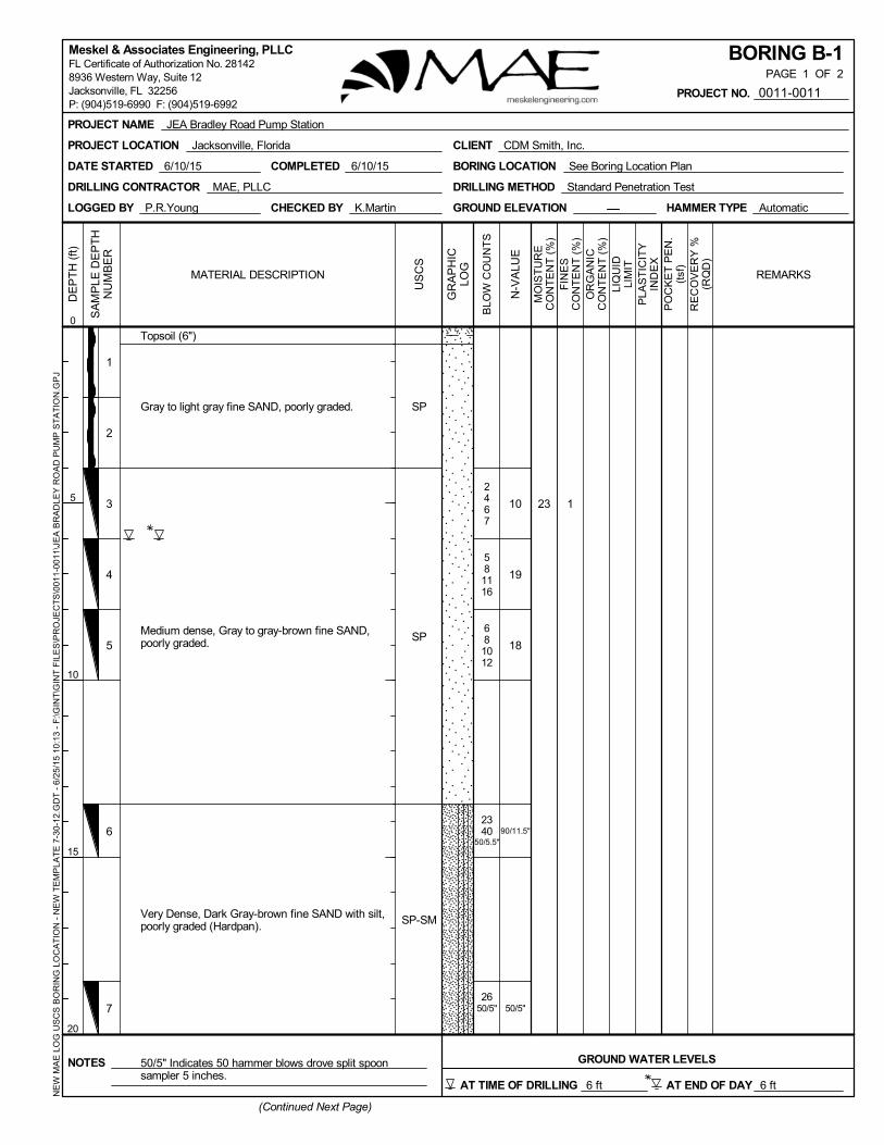
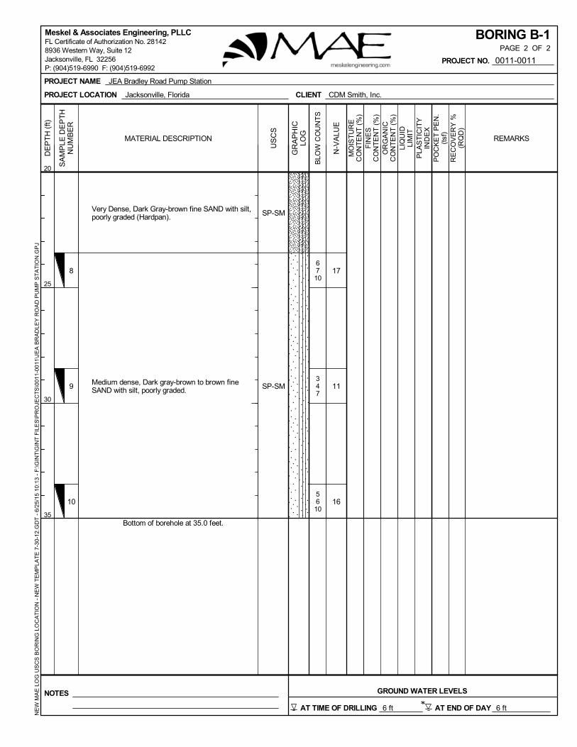
To explore the subsurface conditions within the area of the proposed structures, we located and performed two SPT borings. The borings were each advanced to a depth of 35 feet below the existing ground surface.
Each boring was advanced and continuously sampled to a depth of 10 feet, and then sampled every 5 feet thereafter in general accordance with the methodology outlined in ASTM D-1586. The split-spoon soil samples recovered during performance of the borings were visually described in the field by the field crew, and representative portions of the samples were transported to our laboratory for classification and testing. A summary of the field procedure is included in Appendix A.
2.2 Double Ring Infiltrometer (DRI) Tests
One DRI test was performed at the location shown on Figure 2. The DRI test was set at a depth of approximately 2 feet below the existing ground surface, and was performed in general accordance with the methodology outlined in ASTM D-3385. A hand auger boring was performed to explore the subgrade soils in the area of the DRI test. The soil samples recovered during performance of each boring were described in the field by the field crew. Representative portions of the samples were transported to our laboratory for classification and testing. A summary of the DRI test results, and a summary of the DRI test procedure, are included in Appendix C.
3.0 LABORATORY TESTING
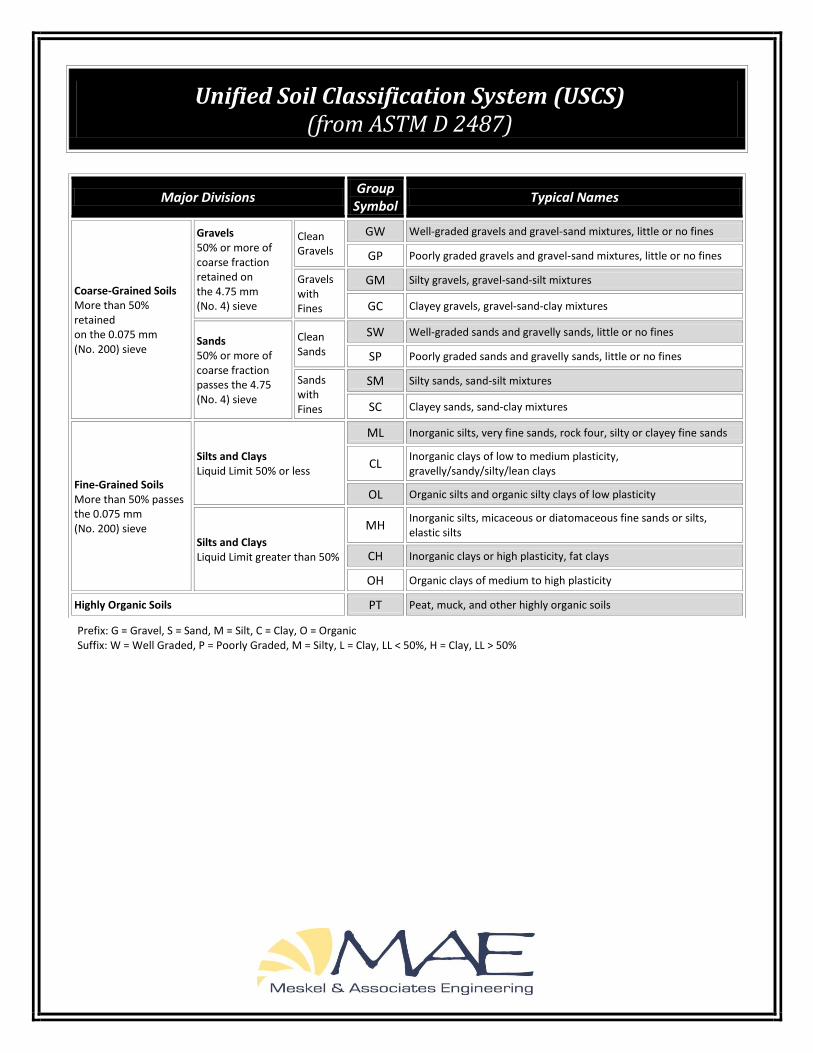
Representative soil samples obtained during our field exploration were visually classified by a geotechnical engineer using the Unified Soil Classification System (USCS) in general accordance with ASTM D-2488. A Key to the Soil Classification System is included in Appendix A.
Quantitative laboratory testing was performed on selected samples of the soils encountered during the field exploration to better define the composition of the soils encountered, and to provide data for correlation to their anticipated strength and compressibility characteristics. The laboratory testing determined the natural moisture content and the percent material finer than the US Sieve No. 200 (percent fines) of the selected soil samples. The results of the laboratory testing are shown in the Summary of Laboratory Test Results included in Appendix B. Also, these results are shown on the Generalized Soil Profiles (Figure 3), and on the Log of Boring records (Appendix A) at the respective depths from which the tested samples were recovered.
4.0 GENERAL SUBSURFACE CONDITIONS
4.1 General Soil Profile
Graphical presentation of the generalized subsurface conditions is presented on the Generalized Soil Profiles, Figure 3. Detailed boring records are included in Appendix A. When reviewing these
JEA Bradley Road Pump Station MAE Final Report No. 0011-0011
8936 Western Way, Suite 12 Jacksonville, Florida 32256
Phone: (904)519-6990 Fax: (904)519-6992
Page | 3
profiles and records, it should be understood that the soil conditions will vary between the boring locations.
In summary, the soil borings encountered a surficial layer of topsoil, approximately 4 to 6 inches in thickness. It should be noted that debris (rock, wood, glass, brick) was observed in the planned construction area, though not encountered in the soil borings. Below the topsoil layer, the borings encountered loose to medium dense to dense fine sands (SP) and fine sands with silt (SP-SM) to a depth of about 13.5 feet below the existing ground surface. The hand auger boring for the DRI test was terminated at a depth of 6 feet within these sandy soils. Below these sands, the SPT borings encountered very dense fine sand with silt (SP-SM), which appeared to be “hardpan” soils, to a depth of about 23.5 feet. Hardpan soils are generally dark brown to dark reddish brown sandy soils with cemented nodules that are bound together by various minerals formed in the soils over time. They were encountered in a very dense state and can be difficult to excavate by normal methods. Below this hardpan layer, the SPT borings encountered medium dense fine sands with silt (SP-SM) to the termination depth of 35 feet.
4.2 Groundwater Level
The groundwater level was encountered at the SPT boring locations and recorded at the time of drilling at depths of approximately 6.0 to 6.25 feet below the existing ground surface. The borings were left open during our field explorations to measure the stabilized groundwater levels, which were measured at the end of day. The stabilized groundwater levels were measured at a depth of 6.0 feet below existing grade.
The hand auger boring at the DRI test location did not encounter groundwater. However, this does not mean that groundwater does not exist at this location, or that groundwater will not be encountered within the depth explored at another time.
It should be anticipated that groundwater levels will fluctuate seasonally and with changes in climate. As such, we recommend that the water table be verified prior to construction. The measured groundwater levels are shown on the boring profiles and boring logs.
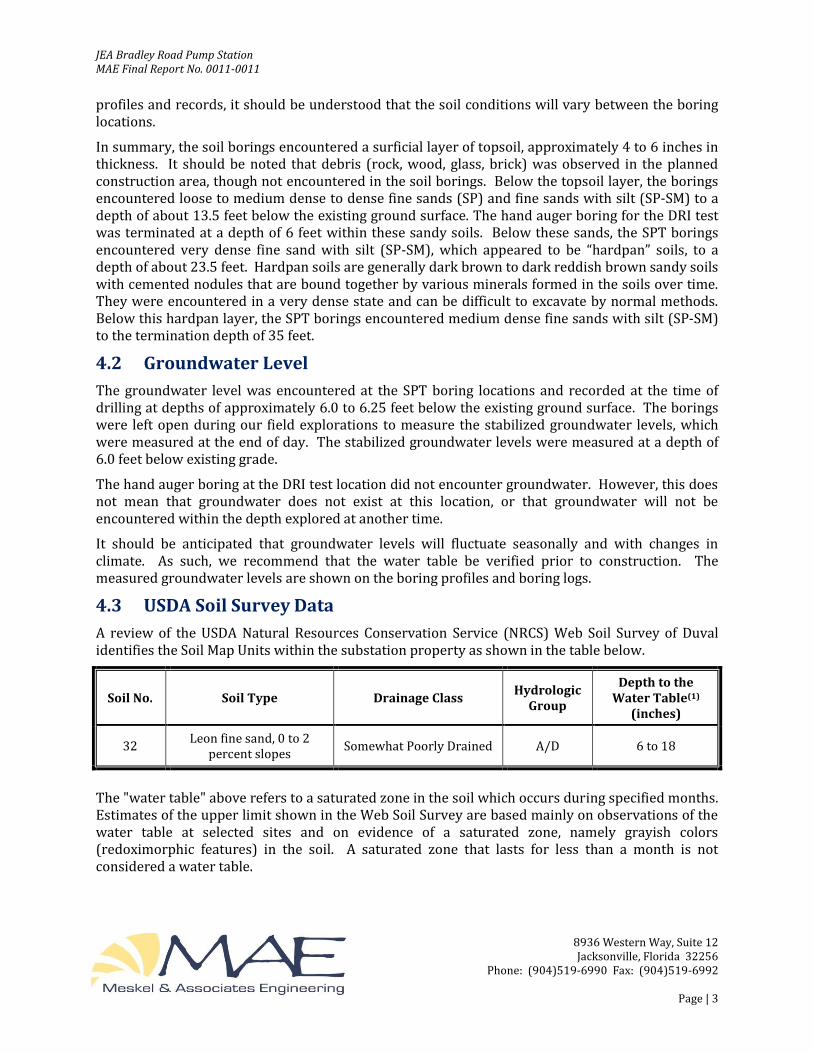
4.3 USDA Soil Survey Data
A review of the USDA Natural Resources Conservation Service (NRCS) Web Soil Survey of Duval identifies the Soil Map Units within the substation property as shown in the table below.
Soil No. Soil Type Drainage Class Hydrologic
Group
Depth to the Water Table(1)
(inches)
32 Leon fine sand, 0 to 2
percent slopes Somewhat Poorly Drained A/D 6 to 18
The "water table" above refers to a saturated zone in the soil which occurs during specified months. Estimates of the upper limit shown in the Web Soil Survey are based mainly on observations of the water table at selected sites and on evidence of a saturated zone, namely grayish colors (redoximorphic features) in the soil. A saturated zone that lasts for less than a month is not considered a water table.

JEA Bradley Road Pump Station MAE Final Report No. 0011-0011
8936 Western Way, Suite 12 Jacksonville, Florida 32256
Phone: (904)519-6990 Fax: (904)519-6992
Page | 4
4.4 Seasonal High Groundwater Level
In estimating seasonal high groundwater level, a number of factors are taken into consideration including antecedent rainfall, soil redoximorphic features (i.e., soil mottling), stratigraphy (including presence of hydraulically restrictive layers), vegetative indicators, effects of development, and relief points such as drainage ditches, low-lying areas, etc.
Based on our interpretation of the current site conditions, including the boring logs and review of published data, we estimate the seasonal high groundwater level at the site to be about 2 to 3 feet above the groundwater levels measured in the borings at the time of our field exploration.
Because of the relatively shallow, very sandy clay soils and the relative flat topography of the site, it is likely that groundwater levels will exceed the estimated normal seasonal high groundwater level as a result of significant or prolonged rains. Therefore, we recommend that design drawings and specifications account for the possibility of groundwater level variations, and construction planning should be based on the assumption that such variations will occur.
5.0 DESIGN RECOMMENDATIONS
5.1 General
The following evaluation and recommendations are based on that provided project information as presented in this report, the results of the field exploration and laboratory testing performed, and the construction techniques recommended in Section 6.0 below. If the described project conditions are incorrect or changed after this report, or if subsurface conditions encountered during construction are different from those reported, MAE should be notified so these recommendations can be re-evaluated and revised, if necessary. We recommend that MAE review the project foundation plans and earthwork specifications to verify that the recommendations in this report have been properly interpreted and implemented.
5.2 Foundation Design Recommendations
Based on the results of our exploration, we consider the subsurface conditions at the site adaptable for support of the proposed structures when constructed on properly designed mat and/or shallow foundation systems. Provided the site preparation and earthwork construction recommendations outlined in Section 6.0 of this report are performed, the following parameters may be used for foundation design.
5.2.1 Bearing Pressure
The maximum allowable net soil bearing pressure for use in shallow foundation design should not exceed 3,000 psf. In addition, the maximum allowable net soil bearing pressure for design of the mat foundations for the pump pad should be 2,000 psf. Net bearing pressure is defined as the soil bearing pressure at the foundation bearing level in excess of the natural overburden pressure at that level. The foundations should be designed based on the maximum load that could be imposed by all loading conditions.
5.2.2 Foundation Size
The minimum width recommended for grade beams and continuous wall footings is 18 inches. The minimum width for the turned-down edges of monolithic slabs is 12 inches. Any isolated pad
JEA Bradley Road Pump Station MAE Final Report No. 0011-0011
8936 Western Way, Suite 12 Jacksonville, Florida 32256
Phone: (904)519-6990 Fax: (904)519-6992
Page | 5
footings should have a minimum dimension of 24 inches. Even though the maximum allowable net soil bearing pressure may not be achieved, these width recommendations should control the size of the foundations.
5.2.3 Bearing Depth
The turned-down edge portion of monolithic slabs, and the pump pad mat foundation, should bear at a minimum depth of 12 inches below outside adjacent finished grades. The continuous wall footings, and any isolated pad footings, should bear at a minimum depth of 18 inches below outside adjacent grades. These minimum depths below exterior final grades are necessary to provide confinement to the bearing level soils. It is recommended that stormwater be diverted away from the building exterior to reduce the possibility of erosion beneath the exterior footings.
5.2.4 Bearing Material
The foundations may bear in either the compacted suitable natural soils or compacted structural fill. The bearing level soils, after compaction, should exhibit densities equivalent to 95 percent of the modified Proctor maximum dry density (ASTM D-1557), to a depth of at least one foot below the foundation bearing levels, for continuous and isolated footings. The upper 12 inches of the mat foundation soils should be compacted to 98 percent of the maximum dry density.
5.2.5 Settlement Estimates
Post-construction settlements of the structure will be influenced by several interrelated factors, such as (1) subsurface stratification and strength/compressibility characteristics; (2) footing size, bearing level, applied loads, and resulting bearing pressures beneath the foundations; and (3) site preparation and earthwork construction techniques used by the contractor. Our settlement estimates for the structure are based on the use of site preparation/earthwork construction techniques as recommended in Section 6.0 of this report. Any deviation from these recommendations could result in an increase in the estimated post-construction settlements of the structure.
Due to the predominately sandy nature of the soils within the expected depth of influence of the assumed foundation loads, we expect the majority of settlement to occur in an elastic manner and fairly rapidly during construction. Using the recommended maximum bearing pressure, the assumed maximum structural loads, and the field and laboratory test data that we have correlated to geotechnical strength and compressibility characteristics of the subsurface soils, we estimate that total settlements of the structures will be on the order of one inch or less.
Differential settlements result from differences in applied bearing pressures and variations in the compressibility characteristics of the subsurface soils. Because of the general uniformity of the encountered subsurface conditions and the recommended site preparation and earthwork construction techniques outlined in Section 6.0, we anticipate that differential settlements of the structures between the center of the loaded area and the outside edges to be one-half inch or less.
5.2.6 Floor Slab
The poured-in-place concrete slabs for the pump pad mat foundations and electrical building floor can be constructed as a grade-supported slab, provided all unsuitable soils are removed and replaced with compacted structural fill as outlined in Section 6.0. We recommend a modulus of subgrade reaction of 150 pci be used for design of the mat/floor slabs. It is recommended that the
JEA Bradley Road Pump Station MAE Final Report No. 0011-0011
8936 Western Way, Suite 12 Jacksonville, Florida 32256
Phone: (904)519-6990 Fax: (904)519-6992
Page | 6
slab bearing soils be covered with an impervious membrane to reduce moisture entry and floor dampness. A 6-mil thick plastic membrane is commonly used for this purpose. Care should be exercised not to tear large sections of the membrane during placement of reinforcing steel and concrete. In addition, we recommend that a minimum separation of 2 feet be maintained between the finished slab levels and the estimated normal seasonal high groundwater level.
5.3 Stormwater Management
The results of the DRI test are shown in Appendix C. A factor of safety of at least 2 should be applied to the design infiltration rate to account for differences in subsurface soil conditions and soil density that will affect permeability, and other factors.
6.0 SITE PREPARATION AND EARTHWORK RECOMMENDATIONS
Site preparation as outlined in this section should be performed to provide more uniform foundation bearing conditions and to reduce the potential for post-construction settlements of the planned structures.
6.1 Clearing and Stripping
Prior to construction, the location of existing underground utility lines within the construction area should be established. Provisions should then be made to relocate interfering utilities to appropriate locations. It should be noted that, if underground pipes are not properly removed or plugged, they may serve as conduits for subsurface erosion, which may subsequently lead to excessive settlement of overlying structures.
The "footprint" of the proposed construction areas, plus a minimum additional margin of 5 feet, should be stripped of all surface vegetation, stumps, debris, organic topsoil, or other deleterious materials, as well as any existing slabs-on-grade or pavements (surface and base courses). It should be noted that surface debris including rocks, wood, glass, brick etc. was observed during our field exploration. During grubbing operations, roots with a diameter greater than 0.5-inch, stumps, or small roots in a concentrated state, should be grubbed and completely removed.
The actual depths of unsuitable soils and materials should be determined by MAE using visual observation and judgment during earthwork operations. Any topsoil removed from the building area can be stockpiled and used subsequently in areas to be grassed.
6.2 Temporary Groundwater Control
Should groundwater control measures become necessary, dewatering methods should be determined by the contractor. We recommend the groundwater control measure remain in place until compaction of the existing soils is completed and until backfilling/site filling has reached a height of 2 feet above the groundwater level at the time of construction. The site should be graded to direct surface water runoff from the construction area.
Note that discharge of produced groundwater to surface waters of the state from dewatering operations or other site activities is regulated and requires a permit from the State of Florida Department of Environmental Protection (FDEP). This permit is termed a Generic Permit for the Discharge of Produced Groundwater From Any Non-Contaminated Site Activity. If discharge of produced groundwater is anticipated, we recommend sampling and testing of the groundwater early in the site design phase to prevent project delays during construction. MAE can provide the
JEA Bradley Road Pump Station MAE Final Report No. 0011-0011
8936 Western Way, Suite 12 Jacksonville, Florida 32256
Phone: (904)519-6990 Fax: (904)519-6992
Page | 7
sampling, testing, and professional consulting required to evaluate compliance with the regulations.
6.3 Compaction
After completing the clearing and stripping operations, and after installing the temporary groundwater control measures if required, we recommend the exposed surface area be compacted with a vibratory roller operating in the static mode have a minimum static weight on the order of at least 10 tons. Typically, the compacted soils should exhibit moisture contents within ±2 percent of the modified Proctor optimum moisture content (ASTM D-1557) during the compaction operation. Several overlapping passes should be made in both directions across the building area, with each pass overlapping the previous pass by at least 30 percent. Compaction should continue until densities of at least 95 percent of the modified Proctor maximum dry density (ASTM D-1557) have been achieved within the upper two feet of the compacted natural soils at the site.
Should the bearing level soils experience pumping and soil strength loss during the compaction operation, compaction work should be immediately terminated, and (1) the disturbed soils should be removed and backfilled with dry structural fill soils, which are then compacted, or (2) the excess moisture content within the disturbed soils should be allowed to dissipate before recompacting.
Due to the proximity of the existing structures, we recommend use of a vibratory roller, operating in the static mode, or a track-mounted bulldozer. Care should be exercised to avoid damaging any nearby structures while the compaction operation is underway. Prior to commencing compaction, occupants of adjacent structures should be notified, and the existing conditions of the structures should be documented with photographs and survey (if deemed necessary). Compaction should cease if deemed detrimental to adjacent structures, and MAE should be contacted immediately.
6.4 Structural Backfill and Fill Soils
Any structural backfill or fill required for site development should be placed in loose lifts not exceeding 8 inches in thickness and compacted by the use of the above described vibratory drum roller operating in the static mode or by track-mounted compaction equipment. If hand-held compaction equipment is used, the lift thickness should be reduced to 6 inches.
Structural fill is defined as a non-plastic, inorganic, granular soil containing less than 10 percent material passing the No. 200 mesh sieve and containing less than 4 percent organic material. The SP and SP-SM soils as encountered at the soil boring locations are considered suitable for use as structural fill. It should be noted that soils with more than 10 percent passing the No. 200 sieve will be more difficult to compact, due to their nature to retain soil moisture, and may require drying. Typically, the material should exhibit moisture contents within ±2 percent of the modified Proctor optimum moisture content (ASTM D-1557) during the compaction operations. Compaction should continue until densities of at least 95 percent of the modified Proctor maximum dry density (ASTM D-1557) have been achieved within each lift of the compacted structural fill.
6.5 Foundation Areas
After satisfactory placement and compaction of the required structural fill, the foundation areas may be excavated to the planned bearing levels. The continuous and isolated pad foundation bearing level soils, after compaction, should exhibit densities equivalent to 95 percent of the modified Proctor maximum dry density (ASTM D-1557), to a depth of one foot below the bearing level. For confined areas, such as the footing excavations, any additional compaction operations can probably best be performed by the use of a lightweight vibratory sled or roller having a total weight on the order of 500 to 2,000 pounds. The subgrade soils below the mat foundation slab should be
JEA Bradley Road Pump Station MAE Final Report No. 0011-0011
8936 Western Way, Suite 12 Jacksonville, Florida 32256
Phone: (904)519-6990 Fax: (904)519-6992
Page | 8
compacted to 98 percent of the modified Proctor maximum dry density.
7.0 QUALITY CONTROL TESTING
A representative number of field in-place density tests should be made in the upper two feet of compacted natural soils, in each lift of compacted backfill and fill, and in the upper 12 inches below the bearing levels in the footing excavations. The density tests are considered necessary to verify that satisfactory compaction operations have been performed. We recommend density testing be performed at one location for every 2,000 square feet of building or slab area with a minimum of 2 test locations, and at one location for every 100 linear feet of continuous wall footings.
8.0 REPORT LIMITATIONS
This report has been prepared for the exclusive use of CDM Smith, Inc. and the JEA for specific application to the design and construction of the Bradley Road Pump Station project. Our work for this project was performed in accordance with generally accepted geotechnical engineering practice. No warranty, express or implied, is made.
The analyses and recommendations contained in this report are based on the data obtained from the borings performed for the Bradley Road Pump Station project. This testing indicates subsurface conditions only at the specific locations and times, and only to the depths explored. These results do not reflect subsurface variations that may exist between the boring locations and/or at depths below the boring termination depths. Subsurface conditions and groundwater levels at other locations may differ from conditions occurring at the tested locations. In addition, it should be understood that the passage of time may result in a change in the conditions at the tested locations. If variations in subsurface conditions from those described in this report are observed during construction, the recommendations in this report must be re-evaluated.
The scope of our services did not include any environmental assessment or testing for the presence or absence of hazardous or toxic materials in the soil, groundwater, or surface water within or beyond the subject site. Any statements made in this report, and/or notations made on the generalized soil profiles or boring logs, regarding odors or other potential environmental concerns are based on observations made during execution of our scope of services and as such are strictly for the information of our client. No opinion of any environmental concern of such observations is made or implied. Unless complete environmental information regarding the site is already available, an environmental assessment is recommended.
If changes in the design or location of the structures occur, the conclusions and recommendations contained in this report may need to be modified. We recommend that these changes be provided to us for our consideration. MAE is not responsible for conclusions, interpretations, opinions or recommendations made by others based on the data contained in this report.

Figures _____________________________________________________________________________________
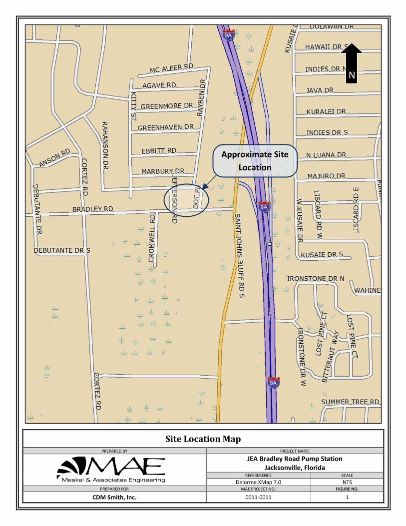
Site Location Map
PREPARED BY PROJECT NAME
JEA Bradley Road Pump Station Jacksonville, Florida
REFERERENCE SCALE
Delorme XMap 7.0 NTS PREPARED FOR MAE PROJECT NO. FIGURE NO.
CDM Smith, Inc. 0011-0011 1
Approximate Site
Location
N
0
5
10
15
20
25
30
35
Legend
CDM Smith, Inc.
MAE PROJECT NO.
BY DESCRIPTION DATE BY DESCRIPTION
SHEET TITLE:
PROJECT NAME:
Natural Moisture Content (%)
DATE
0011-0011
% Passing No. 200 U.S. Standard SieveDepth to Groundwater at Time of Drilling
N
FIGURE NO.
Generalized Soil Profiles
3
Depth (ft)D
epth
(ft
)
w
Boring Terminated at Depth Below GradeBT
DATE:
-200
Standard Penetration Resistance,Blows/Foot
Unified Soil Classification System(SP)Topsoil Fine Sand Fine Sand with Silt (Hardpan)
Fine Sand with Silt
JEA Bradley Road Pump StationJacksonville, FloridaFL Certificate of Authorization No. 28142
8936 Western Way, Suite 12, Jacksonville, FL 32256
50/5"
Boring Advanced by hand-heldbucket auger due to possibleunderground utilities.
*HA
Groundwater Level Not Encountered atTime of Drilling
GNE
Indicates 50 Hammer blows drovesplit spoon sampler 5 inches.
0
5
10
*HA
15
20
25
30
B
DRI Hand Auger boring at DRI test location
35
*HA
SPT Boring
Depth to Groundwater at end of day
10
19
18
17
11
16
BT @ 35.0'.Date Drilled: 6/10/2015
Topsoil (6")
Gray to light gray fine SAND, poorly graded. (SP)
Medium dense, Gray to gray-brown fine SAND,poorly graded. (SP)
Very Dense, Dark Gray-brown fine SAND with silt,poorly graded (Hardpan). (SP-SM)
Medium dense, Dark gray-brown to brown fineSAND with silt, poorly graded. (SP-SM)
90/11.5"
50/5"
12
26
38
78
60
17
10
11
BT @ 35.0'.Date Drilled: 6/10/2015
Topsoil (4")
Gray to light gray fine SAND, poorly graded. (SP)
Medium dense, Dark gray-brown fine SAND withsilt, poorly graded. (SP-SM)
Very dense, Dark gray-brown fine SAND with silt,poorly graded (Hardpan). (SP-SM)
Medium dense, Dark gray-brown to brown to grayfine SAND with silt, poorly graded. (SP-SM)
Very dark brown fine SAND with silt, withcemented nodules and organic fines. (SP-SM)
BT @ 6.0'.Date Drilled: 6/10/2015
GNE
Topsoil (4")
Dark gray-brown fine SAND with silt, poorlygraded. (SP-SM)
9/9/2015
B-1
N
B-2
N N
DRI-1
P. RODNEY MANK, P.E. P.E. NO.: 41986
Meskel & Associates Engineering, PLLC
w = 23-200 = 1
w = 22-200 = 9
w = 23-200 = 10

Appendix A _____________________________________________________________________________________
2310
19
18
2467
581116
681012
50/5" 50/5"
50/5.5"
50/5" Indicates 50 hammer blows drove split spoonsampler 5 inches.
1
2
3
4
5
6
7
1
SP
SP
SP-SM
Topsoil (6")
Gray to light gray fine SAND, poorly graded.
Medium dense, Gray to gray-brown fine SAND,poorly graded.
Very Dense, Dark Gray-brown fine SAND with silt,poorly graded (Hardpan).
GROUND WATER LEVELSNOTES
PROJECT NAME JEA Bradley Road Pump Station
PROJECT LOCATION Jacksonville, Florida
40
CLIENT CDM Smith, Inc.
AT END OF DAY 6 ft
PROJECT NO. 0011-0011
NE
W M
AE
LO
G U
SC
S B
OR
ING
LO
CA
TIO
N -
NE
W T
EM
PLA
TE
7-3
0-12
.GD
T -
6/2
5/15
10
:13
- F
:\GIN
T\G
INT
FIL
ES
\PR
OJE
CT
S\0
011
-001
1\JE
A B
RA
DLE
Y R
OA
D P
UM
P S
TA
TIO
N.G
PJ
Meskel & Associates Engineering, PLLCFL Certificate of Authorization No. 281428936 Western Way, Suite 12Jacksonville, FL 32256P: (904)519-6990 F: (904)519-6992
AT TIME OF DRILLING 6 ft
23
26
90/11.5"
COMPLETED 6/10/15DATE STARTED 6/10/15
DRILLING CONTRACTOR MAE, PLLC
LOGGED BY P.R.Young CHECKED BY K.Martin GROUND ELEVATION HAMMER TYPE Automatic
DRILLING METHOD Standard Penetration Test
BORING LOCATION See Boring Location Plan
MO
IST
UR
EC
ON
TE
NT
(%
)
PLA
ST
ICIT
YIN
DE
X
GR
AP
HIC
LOG
N-V
ALU
E
BLO
W C
OU
NT
S
REMARKS
SA
MP
LE D
EP
TH
NU
MB
ER
(Continued Next Page)
PO
CK
ET
PE
N.
(tsf
)R
EC
OV
ER
Y %
(RQ
D)
FIN
ES
CO
NT
EN
T (
%)
LIQ
UID
LIM
IT
US
CS
MATERIAL DESCRIPTION
DE
PT
H (
ft)
0
5
10
15
20
OR
GA
NIC
CO
NT
EN
T (
%)
BORING B-1PAGE 1 OF 2
17
11
16
6710
347
5610
8
9
10
SP-SM
SP-SM
Very Dense, Dark Gray-brown fine SAND with silt,poorly graded (Hardpan).
Medium dense, Dark gray-brown to brown fineSAND with silt, poorly graded.
Bottom of borehole at 35.0 feet.
MO
IST
UR
EC
ON
TE
NT
(%
)
PLA
ST
ICIT
YIN
DE
X
GR
AP
HIC
LOG
N-V
ALU
E
BLO
W C
OU
NT
S
REMARKS
SA
MP
LE D
EP
TH
NU
MB
ER
PO
CK
ET
PE
N.
(tsf
)R
EC
OV
ER
Y %
(RQ
D)
FIN
ES
CO
NT
EN
T (
%)
LIQ
UID
LIM
IT
US
CS
MATERIAL DESCRIPTION
DE
PT
H (
ft)
20
25
30
35
OR
GA
NIC
CO
NT
EN
T (
%)
BORING B-1PAGE 2 OF 2
GROUND WATER LEVELSNOTES
PROJECT NAME JEA Bradley Road Pump Station
PROJECT LOCATION Jacksonville, Florida CLIENT CDM Smith, Inc.
PROJECT NO. 0011-0011
NE
W M
AE
LO
G U
SC
S B
OR
ING
LO
CA
TIO
N -
NE
W T
EM
PLA
TE
7-3
0-12
.GD
T -
6/2
5/15
10
:13
- F
:\GIN
T\G
INT
FIL
ES
\PR
OJE
CT
S\0
011
-001
1\JE
A B
RA
DLE
Y R
OA
D P
UM
P S
TA
TIO
N.G
PJ
Meskel & Associates Engineering, PLLCFL Certificate of Authorization No. 281428936 Western Way, Suite 12Jacksonville, FL 32256P: (904)519-6990 F: (904)519-6992
AT TIME OF DRILLING 6 ft AT END OF DAY 6 ft
22
12
26
38
78
60
35710
691725
10132531
133048
152436
1
2
3
4
5
6
7
9
SP
SP-SM
SP-SM
Topsoil (4")
Gray to light gray fine SAND, poorly graded.
Medium dense, Dark gray-brown fine SAND withsilt, poorly graded.
Very dense, Dark gray-brown fine SAND with silt,poorly graded (Hardpan).
COMPLETED 6/10/15DATE STARTED 6/10/15
DRILLING CONTRACTOR MAE, PLLC
LOGGED BY P.R.Young CHECKED BY K.Martin GROUND ELEVATION HAMMER TYPE Automatic
DRILLING METHOD Standard Penetration Test
BORING LOCATION See Boring Location Plan
MO
IST
UR
EC
ON
TE
NT
(%
)
PLA
ST
ICIT
YIN
DE
X
GR
AP
HIC
LOG
N-V
ALU
E
BLO
W C
OU
NT
S
REMARKS
SA
MP
LE D
EP
TH
NU
MB
ER
(Continued Next Page)
PO
CK
ET
PE
N.
(tsf
)R
EC
OV
ER
Y %
(RQ
D)
FIN
ES
CO
NT
EN
T (
%)
LIQ
UID
LIM
IT
US
CS
MATERIAL DESCRIPTION
DE
PT
H (
ft)
0
5
10
15
20
OR
GA
NIC
CO
NT
EN
T (
%)
BORING B-2PAGE 1 OF 2
GROUND WATER LEVELSNOTES
PROJECT NAME JEA Bradley Road Pump Station
PROJECT LOCATION Jacksonville, Florida CLIENT CDM Smith, Inc.
PROJECT NO. 0011-0011
AT END OF DAY 6 ft
NE
W M
AE
LO
G U
SC
S B
OR
ING
LO
CA
TIO
N -
NE
W T
EM
PLA
TE
7-3
0-12
.GD
T -
6/2
5/15
10
:13
- F
:\GIN
T\G
INT
FIL
ES
\PR
OJE
CT
S\0
011
-001
1\JE
A B
RA
DLE
Y R
OA
D P
UM
P S
TA
TIO
N.G
PJ
Meskel & Associates Engineering, PLLCFL Certificate of Authorization No. 281428936 Western Way, Suite 12Jacksonville, FL 32256P: (904)519-6990 F: (904)519-6992
AT TIME OF DRILLING 6.3 ft
17
10
11
589
346
938
8
9
10
SP-SM
SP-SM
Very dense, Dark gray-brown fine SAND with silt,poorly graded (Hardpan).
Medium dense, Dark gray-brown to brown to grayfine SAND with silt, poorly graded.
Bottom of borehole at 35.0 feet.
MO
IST
UR
EC
ON
TE
NT
(%
)
PLA
ST
ICIT
YIN
DE
X
GR
AP
HIC
LOG
N-V
ALU
E
BLO
W C
OU
NT
S
REMARKS
SA
MP
LE D
EP
TH
NU
MB
ER
PO
CK
ET
PE
N.
(tsf
)R
EC
OV
ER
Y %
(RQ
D)
FIN
ES
CO
NT
EN
T (
%)
LIQ
UID
LIM
IT
US
CS
MATERIAL DESCRIPTION
DE
PT
H (
ft)
20
25
30
35
OR
GA
NIC
CO
NT
EN
T (
%)
BORING B-2PAGE 2 OF 2
GROUND WATER LEVELSNOTES
PROJECT NAME JEA Bradley Road Pump Station
PROJECT LOCATION Jacksonville, Florida CLIENT CDM Smith, Inc.
PROJECT NO. 0011-0011
AT END OF DAY 6 ft
NE
W M
AE
LO
G U
SC
S B
OR
ING
LO
CA
TIO
N -
NE
W T
EM
PLA
TE
7-3
0-12
.GD
T -
6/2
5/15
10
:13
- F
:\GIN
T\G
INT
FIL
ES
\PR
OJE
CT
S\0
011
-001
1\JE
A B
RA
DLE
Y R
OA
D P
UM
P S
TA
TIO
N.G
PJ
Meskel & Associates Engineering, PLLCFL Certificate of Authorization No. 281428936 Western Way, Suite 12Jacksonville, FL 32256P: (904)519-6990 F: (904)519-6992
AT TIME OF DRILLING 6.3 ft
23
1
2
3
4
10
SP-SM
SP-SM
Topsoil (4")
Dark gray-brown fine SAND with silt, poorlygraded.
Very dark brown fine SAND with silt, withcemented nodules and organic fines.
Bottom of borehole at 6.0 feet.
COMPLETED 6/10/15DATE STARTED 6/10/15
DRILLING CONTRACTOR MAE, PLLC
LOGGED BY P.R.Young CHECKED BY K.Martin GROUND ELEVATION HAMMER TYPE
DRILLING METHOD Hand Auger
BORING LOCATION See Boring Location Plan
MO
IST
UR
EC
ON
TE
NT
(%
)
PLA
ST
ICIT
YIN
DE
X
GR
AP
HIC
LOG
N-V
ALU
E
BLO
W C
OU
NT
S
REMARKS
SA
MP
LE D
EP
TH
NU
MB
ER
PO
CK
ET
PE
N.
(tsf
)R
EC
OV
ER
Y %
(RQ
D)
FIN
ES
CO
NT
EN
T (
%)
LIQ
UID
LIM
IT
US
CS
MATERIAL DESCRIPTION
DE
PT
H (
ft)
0.0
2.5
5.0
OR
GA
NIC
CO
NT
EN
T (
%)
BORING DRI-1PAGE 1 OF 1
GROUND WATER LEVELSNOTES
AFTER DRILLING ---AT TIME OF DRILLING --- GNE
PROJECT NAME JEA Bradley Road Pump Station
PROJECT LOCATION Jacksonville, Florida CLIENT CDM Smith, Inc.
PROJECT NO. 0011-0011
NE
W M
AE
LO
G U
SC
S B
OR
ING
LO
CA
TIO
N -
NE
W T
EM
PLA
TE
7-3
0-12
.GD
T -
6/2
5/15
10
:30
- F
:\GIN
T\G
INT
FIL
ES
\PR
OJE
CT
S\0
011
-001
1\JE
A B
RA
DLE
Y R
OA
D P
UM
P S
TA
TIO
N.G
PJ
Meskel & Associates Engineering, PLLCFL Certificate of Authorization No. 281428936 Western Way, Suite 12Jacksonville, FL 32256P: (904)519-6990 F: (904)519-6992
GNE- Groundwater Level Not Encountered at Timeof Drilling.
FIELD EXPLORATION PROCEDURES
Standard Penetration Test (SPT) Borings
The Standard Penetration Test (SPT) boring(s) were performed in general accordance with
the latest revision of ASTM D 1586, “Penetration Test and Split-Barrel Sampling of Soils.”
The borings were advanced by rotary drilling techniques. A split-barrel sampler was
inserted to the borehole bottom and driven 18 to 24 inches into the soil using a 140 pound
hammer falling an average of 30 inches per hammer blow. The number of hammer blows
for the final 12 inches of penetration (18” sample) or for the sum of the middle 12 inches of
penetration (24” sample) is termed the “penetration resistance, blow count, or N-value.”
This value is an index to several in-situ geotechnical properties of the material tested, such
as relative density and Young’s Modulus.
After driving the sampler, it was retrieved from the borehole and representative samples of
the material within the split-barrel were containerized and sealed. After completing the
drilling operations, the samples for each boring were transported to the laboratory where
they were examined by our engineer in order to verify the field classification.
KBL-USCS-Auto
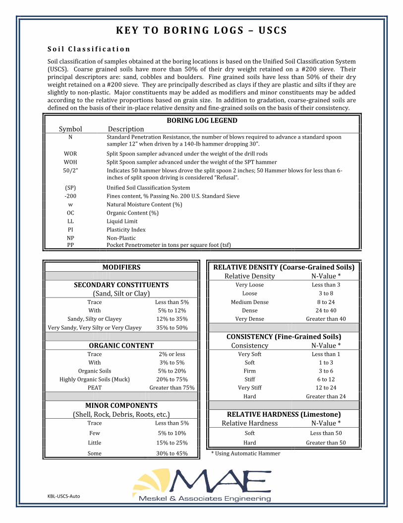
K E Y T O B O R I N G L O G S – U S C S
S o i l C l a s s i f i c a t i o n
Soil classification of samples obtained at the boring locations is based on the Unified Soil Classification System (USCS). Coarse grained soils have more than 50% of their dry weight retained on a #200 sieve. Their principal descriptors are: sand, cobbles and boulders. Fine grained soils have less than 50% of their dry weight retained on a #200 sieve. They are principally described as clays if they are plastic and silts if they are slightly to non-plastic. Major constituents may be added as modifiers and minor constituents may be added according to the relative proportions based on grain size. In addition to gradation, coarse-grained soils are defined on the basis of their in-place relative density and fine-grained soils on the basis of their consistency.
BORING LOG LEGEND Symbol Description
N Standard Penetration Resistance, the number of blows required to advance a standard spoon sampler 12" when driven by a 140-lb hammer dropping 30".
WOR Split Spoon sampler advanced under the weight of the drill rods
WOH Split Spoon sampler advanced under the weight of the SPT hammer
50/2” Indicates 50 hammer blows drove the split spoon 2 inches; 50 Hammer blows for less than 6-inches of split spoon driving is considered “Refusal”.
(SP) Unified Soil Classification System
-200 Fines content, % Passing No. 200 U.S. Standard Sieve
w Natural Moisture Content (%)
OC Organic Content (%)
LL Liquid Limit
PI Plasticity Index
NP PP
Non-Plastic Pocket Penetrometer in tons per square foot (tsf)
MODIFIERS
RELATIVE DENSITY (Coarse-Grained Soils)
Relative Density N-Value * SECONDARY CONSTITUENTS
Very Loose Less than 3
(Sand, Silt or Clay)
Loose 3 to 8
Trace Less than 5%
Medium Dense 8 to 24
With 5% to 12%
Dense 24 to 40
Sandy, Silty or Clayey 12% to 35%
Very Dense Greater than 40
Very Sandy, Very Silty or Very Clayey 35% to 50%
CONSISTENCY (Fine-Grained Soils)
ORGANIC CONTENT
Consistency N-Value * Trace 2% or less
Very Soft Less than 1
With 3% to 5%
Soft 1 to 3
Organic Soils 5% to 20%
Firm 3 to 6
Highly Organic Soils (Muck) 20% to 75%
Stiff 6 to 12
PEAT Greater than 75%
Very Stiff 12 to 24
Hard Greater than 24
MINOR COMPONENTS
(Shell, Rock, Debris, Roots, etc.)
RELATIVE HARDNESS (Limestone) Trace Less than 5%
Relative Hardness N-Value *
Few 5% to 10%
Soft Less than 50
Little 15% to 25%
Hard Greater than 50
Some 30% to 45%
* Using Automatic Hammer
Prefix: G = Gravel, S = Sand, M = Silt, C = Clay, O = Organic Suffix: W = Well Graded, P = Poorly Graded, M = Silty, L = Clay, LL < 50%, H = Clay, LL > 50%
Unified Soil Classification System (USCS) (from ASTM D 2487)
Major Divisions Group
Symbol Typical Names
Coarse-Grained Soils More than 50% retained on the 0.075 mm (No. 200) sieve
Gravels 50% or more of coarse fraction retained on the 4.75 mm (No. 4) sieve
Clean Gravels
GW Well-graded gravels and gravel-sand mixtures, little or no fines
GP Poorly graded gravels and gravel-sand mixtures, little or no fines
Gravels with Fines
GM Silty gravels, gravel-sand-silt mixtures
GC Clayey gravels, gravel-sand-clay mixtures
Sands 50% or more of coarse fraction passes the 4.75 (No. 4) sieve
Clean Sands
SW Well-graded sands and gravelly sands, little or no fines
SP Poorly graded sands and gravelly sands, little or no fines
Sands with Fines
SM Silty sands, sand-silt mixtures
SC Clayey sands, sand-clay mixtures
Fine-Grained Soils More than 50% passes the 0.075 mm (No. 200) sieve
Silts and Clays Liquid Limit 50% or less
ML Inorganic silts, very fine sands, rock four, silty or clayey fine sands
CL Inorganic clays of low to medium plasticity, gravelly/sandy/silty/lean clays
OL Organic silts and organic silty clays of low plasticity
Silts and Clays Liquid Limit greater than 50%
MH Inorganic silts, micaceous or diatomaceous fine sands or silts, elastic silts
CH Inorganic clays or high plasticity, fat clays
OH Organic clays of medium to high plasticity
Highly Organic Soils PT Peat, muck, and other highly organic soils

Appendix B _____________________________________________________________________________________
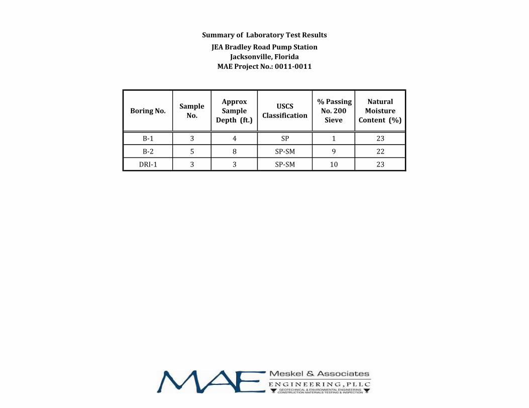
B-1 3 4 SP 1 23
B-2 5 8 SP-SM 9 22
DRI-1 3 3 SP-SM 10 23
Natural Moisture
Content (%)
% Passing No. 200
Sieve
Boring No. Approx Sample
Depth (ft.)
USCS
Classification
Sample
No.
Summary of Laboratory Test Results
JEA Bradley Road Pump Station
Jacksonville, Florida
MAE Project No.: 0011-0011
LABORATORY TEST PROCEDURES
Percent Fines Content
The percent fines or material passing the No. 200 mesh sieve of the sample tested was
determined in general accordance with the latest revision of ASTM D 1140. The percent
fines are the soil particles in the silt and clay size range.
Natural Moisture Content
The water content of the tested sample was determined in general accordance with the
latest revision of ASTM D 2216. The water content is defined as the ratio of “pore” or “free”
water in a given mass of material to the mass of solid material particles.

Appendix C _____________________________________________________________________________________
Double Ring Infiltrometer Test Summary Sheet
Project Name: JEA Bradley Road Pump StationJacksonvilleDuval County, Florida
Test No.: DRI-1
Date Performed: 6/10/2015
Test Location: DRI-1 Performed by: PR Young
MAE Project No.: 0011-0011
Groundwater Depth: Not Encountered
Test Depth: 2.0 feet
Soil Description: See Boring log DRI-1
Comments: Rings were re-filled when needed due to the infiltration rates measured in the field.
ASTM D3385
0
5
10
15
20
25
30
35
40
0 5 10 15 20 25 30 35 40 45 50 55 60 65 70 75 80 85 90 95 100 105 110 115 120
Infi
ltra
tio
n R
ate
(in
/hr)
Time (min)
Double Ring Infiltrometer Test Results Infiltration Rate Versus Time
Inner Ring
Annular Space
Average Infiltration Rate: 12 in/hr
FIELD EXPLORATION PROCEDURES
Double-Ring Infiltrometer Test
The Double-Ring Infiltrometer test was performed in the field in general accordance with
the procedures outlined in the latest revision of ASTM D 3385, “Infiltration Rate of Soils in
Field using Double-Ring Infiltrometers.” The test location was initially cleared of all surface
vegetation and topsoil, excavated to the desired test depth and then leveled. The outer
ring, approximately 24 inches in diameter, was driven to a depth of 6 inches below the test
depth. The inner ring, approximately 12 inches in diameter, was inserted inside the outer
ring, centered, and driven to a depth of approximately 2 inches below the test depth. A thin
layer of gravel was placed on the exposed soils inside the rings at the test level. The two
rings were filled simultaneously with 4 inches of water.
This water level maintained throughout the test period, with the required amount of water
added to maintain this level in both rings recorded at time intervals of five minutes. After
reaching a stabilized inflow volume of water, the test was continued for approximately 120
minutes. To determine the infiltration rate, the volume of water used during the stabilized
flow period for the inner ring, the annular space and both rings combined is converted to
the depth of water per unit of time (e.g., in inches per hour).