jeep grand cherokee (wk) jeep commander (xk) · pdf filecompletely in place and no circuit ......
TRANSCRIPT

123456789012345678901234567890121234567890123456789012345678901123456789012345678901234567890121234567890123456789012345678901123456789012345678901234567890121234567890123456789012345678901123456789012345678901234567890121234567890123456789012345678901123456789012345678901234567890121234567890123456789012345678901123456789012345678901234567890121234567890123456789012345678901123456789012345678901234567890121234567890123456789012345678901123456789012345678901234567890121234567890123456789012345678901123456789012345678901234567890121234567890123456789012345678901123456789012345678901234567890121234567890123456789012345678901123456789012345678901234567890121234567890123456789012345678901123456789012345678901234567890121234567890123456789012345678901123456789012345678901234567890121234567890123456789012345678901123456789012345678901234567890121234567890123456789012345678901
INSTALLATION INSTRUCTIONSProfessional Installation is Recommended
Technical SupportFor Authorized Dealers - (800) 34-MOPARHours: 9:00 a.m. - 6:00 p.m. EST Monday thru Friday
10:00 a.m. - 2:00 p.m. EST Saturday1030930REV. A8/05 K6859684
Jeep Grand Cherokee (WK)Jeep Commander (XK)
Security System
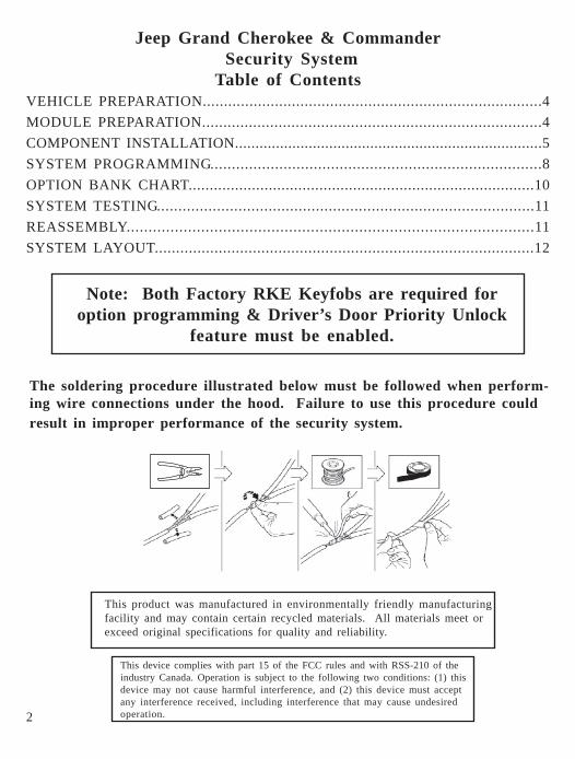
Note: Both Factory RKE Keyfobs are required foroption programming & Driver’s Door Priority Unlock
feature must be enabled.
2
This device complies with part 15 of the FCC rules and with RSS-210 of theindustry Canada. Operation is subject to the following two conditions: (1) thisdevice may not cause harmful interference, and (2) this device must acceptany interference received, including interference that may cause undesiredoperation.
This product was manufactured in environmentally friendly manufacturingfacility and may contain certain recycled materials. All materials meet orexceed original specifications for quality and reliability.
Jeep Grand Cherokee & Commander Security SystemTable of Contents
VEHICLE PREPARATION................................................................................4MODULE PREPARATION................................................................................4COMPONENT INSTALLATION...........................................................................5SYSTEM PROGRAMMING.............................................................................8OPTION BANK CHART..................................................................................10SYSTEM TESTING........................................................................................11REASSEMBLY.............................................................................................11SYSTEM LAYOUT.........................................................................................12
123456789012345678901234567890121234567890123456789012345678901123456789012345678901234567890121234567890123456789012345678901123456789012345678901234567890121234567890123456789012345678901123456789012345678901234567890121234567890123456789012345678901123456789012345678901234567890121234567890123456789012345678901123456789012345678901234567890121234567890123456789012345678901123456789012345678901234567890121234567890123456789012345678901123456789012345678901234567890121234567890123456789012345678901123456789012345678901234567890121234567890123456789012345678901123456789012345678901234567890121234567890123456789012345678901123456789012345678901234567890121234567890123456789012345678901123456789012345678901234567890121234567890123456789012345678901
Note: Both Factory RKE Keyfobs are required foroption programming & Driver’s Door Priority Unlock
feature must be enabled.
The soldering procedure illustrated below must be followed when perform-ing wire connections under the hood. Failure to use this procedure couldresult in improper performance of the security system.

3
PARTS REQUIREDPart Number 82209709 (WK) or 82209710 (XK)
5A 1X 15A 1X 1X 5X
Owner's Manual
Vehicle Remote Start System
TM
Featuring PowerCode TechnologyFor the Ultimate in Comfort, Convenience and Security
TM
®
TOOLS REQUIRED
10mm 1/4”
RTV SEALENT
VEHICLE PREPARATION1. Lower one or more of the passenger windows so the keys do not get locked
in the vehicle.2. Disconnect and isolate the negative battery cable. The battery will need to be
re-connected before programming.3. System installation requires 2 working factory RKE keyfobs for pro-
gramming options.
TM
T-20
WK/XK HORN & PARK LIGHT JUMPER
12345123451234512345T-20

4
Vehicle PreparationRemove driver’s side lower dashpanels, located directly under thesteering column and left kick panel.A. Pull down lower dash & remove.
B. Remove (2) screws from blackunder dash panel & remove.
C. Remove left kick panel and sillplate by gently pulling them off.
OverviewThe security module harness will interface with the existing ignition switch connec-tor, horn, parking lights, power doorlock & door trigger connections, and a groundtermination.
Module PreparationPlace fuses into the control module.A. Observe fuse amperage ratings.
Place the 5 Amp fuse into the “MainB+” location. Place the 15 Amp fuseinto the negative “PK LIGHTS”location.
Install DNA into the control moduleB. Insert DNA into the control module.
Ensure the DNA assembly snapscompletely in place and no circuitboard pins get bent while closing.
DNA
5
PIN #1
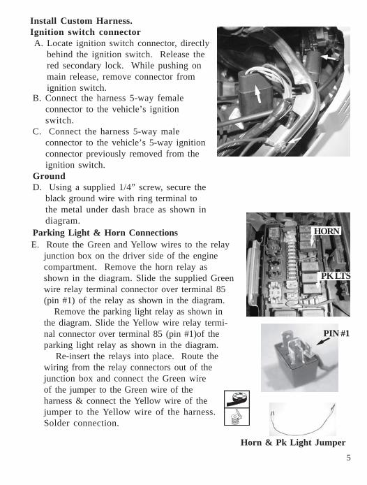
E. Route the Green and Yellow wires to the relayjunction box on the driver side of the enginecompartment. Remove the horn relay asshown in the diagram. Slide the supplied Greenwire relay terminal connector over terminal 85(pin #1) of the relay as shown in the diagram.
Remove the parking light relay as shown inthe diagram. Slide the Yellow wire relay termi-nal connector over terminal 85 (pin #1)of theparking light relay as shown in the diagram.
Re-insert the relays into place. Route thewiring from the relay connectors out of thejunction box and connect the Green wireof the jumper to the Green wire of theharness & connect the Yellow wire of thejumper to the Yellow wire of the harness.Solder connection.
Parking Light & Horn Connections
B. Connect the harness 5-way femaleconnector to the vehicle’s ignitionswitch.
C. Connect the harness 5-way maleconnector to the vehicle’s 5-way ignitionconnector previously removed from theignition switch.
GroundD. Using a supplied 1/4” screw, secure the
black ground wire with ring terminal tothe metal under dash brace as shown indiagram.
Install Custom Harness.Ignition switch connectorA. Locate ignition switch connector, directly
behind the ignition switch. Release thered secondary lock. While pushing onmain release, remove connector fromignition switch.
12345671234567HORN
123456781234567812345678PK LTS
Horn & Pk Light Jumper

6
Arm Wire ConnectionF. Locate the Lt Green/Lt Blue wire,
found in the harness in the left kickpanel. This wire will show +12vwhen the doors are locked usingthe RKE keyfob. Center-splice theharness Lt Blue wire into this wire,following the center-splice proce-dure.
Disarm Wire ConnectionG. Locate the Lt Green/Dk Green
wire, found in the harness in the leftkick panel. This wire will show+12v when the driver door isunlocked using the RKE keyfob(first press). Center-splice theharness Brown wire into this wire,following the center-splice proce-dure.
Unlock Sense Wire ConnectionH. Locate the Lt Green/Tan wire,
found in the harness in the lowerleft kick panel/sill. This wire willshow +12v when all doors areunlocked on the second press ofthe unlock button using the RKEkeyfob. Center-splice the harnessLt Green wire into this wire, follow-ing the center-splice procedure.
Door Trigger ConnectionI. Locate the Yellow/Orange wire, found at the under
dash light. Center-splice the harness White wire intothis wire, following the center-splice procedure.
Center-splice Procedure
Power Door Lock Connections - Battery will need to be reconnected totest wires
7
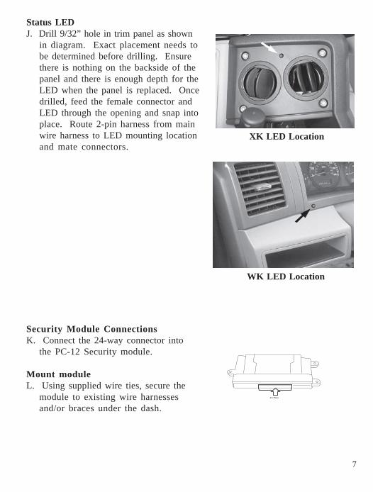
Security Module ConnectionsK. Connect the 24-way connector into
the PC-12 Security module.
Mount moduleL. Using supplied wire ties, secure the
module to existing wire harnessesand/or braces under the dash.
Status LEDJ. Drill 9/32” hole in trim panel as shown
in diagram. Exact placement needs tobe determined before drilling. Ensurethere is nothing on the backside of thepanel and there is enough depth for theLED when the panel is replaced. Oncedrilled, feed the female connector andLED through the opening and snap intoplace. Route 2-pin harness from mainwire harness to LED mounting locationand mate connectors.
XK LED Location
WK LED Location

8
Option Programming.The remote security system has several installer programmable options whichcan be changed to accomodate different circumstances. In most cases, therewill be a need to change option settings (i.e. adjustment of shock sensorsensitivity, horn pulse output duration, etc).
A. Open the driver’s door.B. Turn the ignition to the “on” position.C. Press and hold the programming/override button; After 10 seconds the
parking lights will flash 3 times indicating the system is now in learnmode.
D. Release the programming button.E. Press and release the programming button once more; The parking
lights will flash 4 times indicating the system has entered Option Bank 1.
System ProgrammingNotes:1. Reconnect the negative battery terminal prior to programming.2. System installation requires 2 working factory RKE keyfobs for pro-
gramming options.3. Ensure Driver’s Door Priority Unlock feature is enabled for proper
operation of security system. Refer to vehicle’s Service Manual.4. This system has 2 option banks. Bank 1 has 8 options, and Bank 2
has 4 options. Refer to the Option Bank Chart on page 11 for details.
To change the setting of an option:A. Press the door trim “Lock” switch or, if the vehicle’s door lock feature is
non-functional with the ignition turned on, press the factory keyfob“Lock” button (of the keyfob that is not in the ignition cylinder) to advanceto the desired option (refer to the Option Bank Chart).
The parking lights will flash a number of times indicating which optionis selected (i.e. Two flashes indicates that option number two has beenselected).
B. Press the door trim “Unlock” switch to change the setting of an option.. The status LED indicates the setting of the option; LED ON indicates
that the option is on, LED OFF indicates that the option is off.C. To advance to Option Bank 2, at any point while in Option Bank 1, press
and release the programming/override button to advance to option banknumber two. The parking lights will flash 5 times indicating the systemhas entered Option Bank 2.
To return back to Option Bank 1, press and release the programming/override button once again (4 flashes).
9
Shock sensor setting: (Ensure module is mounted before adjustment!)The “Lite-touch” and “Full shock” sensor settings are always the first and
second options, respectively, in Option Bank 1. To change the shocksensor setting, follow these steps:
A. Make sure the driver’s window is rolled down.B. Enter Option Learn Mode, Option Bank 1, as shown on page 9.C. Go to option #1 for Lite-touch (parking lights flash 1 time).D. Close all doors (wait for domelight to turn off).E. Press the door trim “Unlock” switch to increase sensitivity and press the
door trim “Lock” switch to decrease sensitivity.F. Test the shock sensor sensitivity (while in option learn mode) by
applying an impact with an open hand to the windshield. Caution -make sure to remove articles of jewelry to avoid scratching orbreaking glass.
The parking lights will flash each time an impact is detected that isgreater than the current setting.
G. Once the desired Lite-touch sensitivity is achieved, open a door toadvance to the Full shock option by pressing the door trim “Lock” switchor, if the vehicle’s door lock feature is non-functional with the ignitionturned on, press the factory keyfob “Lock” button (parking lights flash 2times). Repeat steps D through F to set Full shock sensitivity.
H. Open a door to continue with “To change the setting of an option” onpage 9 (if necessary).

10
.
*If the horn does not honk when the systems is triggered, turn off Option #3 inOption Bank #1.
Option Bank 1 – 4 flashes1 – Lite-touch adjustment2 – Full shock adjustment3 – Horn pulse short/long*On - Short output, Off - Long output...............................................................................On4 – Selectable chirpsEnables arming/disarming confirmation chirps.........................................................On5 – Silent choice................................................................................................................OnOn – Confirmation chirp on second press of transmitter buttonOff – Confirmation chirp on first press of transmitter button.Requires option #4(above) to be ON............................................................................On6 – Not used7 – Optional alarm disableDisables security functionality........................................................................................Off8 – Noise controlLimits alarm trips to 5 per zone.....................................................................................On
Option Bank 2 – 5 flashes1 – Door ajar switch input polarityLED On – Positive, LED Off – Negative........................................................................Off2 – Unlock switch sense input polarityLED On – Positive, LED Off – Negative........................................................................On3 - Not used4 – Door ajar input entry delay(5) Five Second entry delay. ...........................................................................................Off
FACTORY SETTING
FACTORY SETTING
Option Programming - Option Banks
11
Dash reassembly.A. Reverse the dash dissassembly procedure.
Reassembly Component mounting. A. Mount security module to existing underdash braces or wire harnesses using the supplied wire ties. Avoid moving parts (steering column, brake pedal assembly).
B. Using supplied wire ties, secure the security module harness to existingwire harnesses under the left side of the dash. Ensure no wires will becomeentangled in the steering column knuckle and that they are not visible tovehicle occupants.
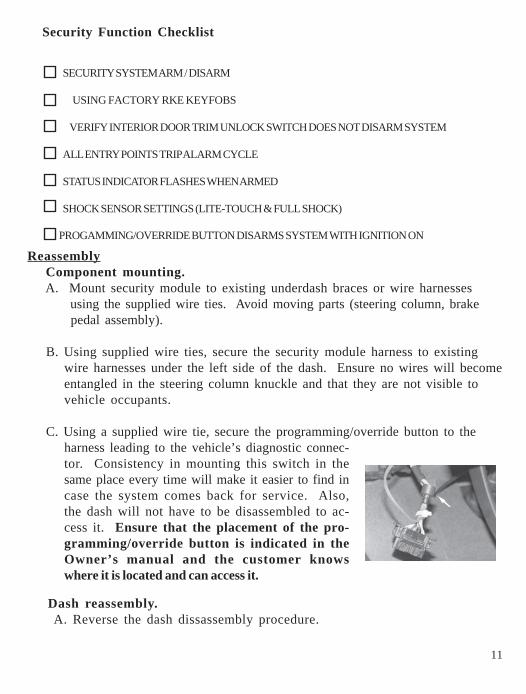
C. Using a supplied wire tie, secure the programming/override button to theharness leading to the vehicle’s diagnostic connec-tor. Consistency in mounting this switch in thesame place every time will make it easier to find incase the system comes back for service. Also,the dash will not have to be disassembled to ac-cess it. Ensure that the placement of the pro-gramming/override button is indicated in theOwner’s manual and the customer knowswhere it is located and can access it.
SECURITY SYSTEM ARM / DISARM
USING FACTORY RKE KEYFOBS
VERIFY INTERIOR DOOR TRIM UNLOCK SWITCH DOES NOT DISARM SYSTEM
ALL ENTRY POINTS TRIP ALARM CYCLE
STATUS INDICATOR FLASHES WHEN ARMED
SHOCK SENSOR SETTINGS (LITE-TOUCH & FULL SHOCK)
Security Function Checklist
PROGAMMING/OVERRIDE BUTTON DISARMS SYSTEM WITH IGNITION ON
12
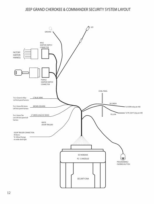
PROGRAMMING/OVERRIDE BUTTON
FACTORYIGNITIONHARNESS
MALE IGNITION SWITCHCONNECTOR
FEMALE IGNITION SWITCHCONNECTOR
05140464AA
PC-12 MODULE
SECURITY DNA
LED
GROUND
COWL PANEL
DK GREEN
JEEP GRAND CHEROKEE & COMMANDER SECURITY SYSTEM LAYOUT
To HORN relay pin #85
LT BLUE (ARM)
BROWN (DISARM)
LT GREEN (UNLOCK SENSE)
WHITE (DOOR TRIGGER)
To Lt Green/Lt BlueLeft kick panel harness
To Lt Green/Dk Green Left kick panel harness
To Lt Green/Tan Low left kick panel/sillharness
All doors - To Yellow/Orangeat under dash light
DOOR TRIGGER CONNECTION:
YELLOWTo PK LIGHT relay pin #85