jeevaka industries private...
TRANSCRIPT

JEEVAKA INDUSTRIES PRIVATE LIMITED (Sponge Iron division)
Nasthipur & Mangapur Villages Hatnoora Mandal
Sangareddy District Telangana
Pre-Feasibility Report
(Expansion of Sponge Iron from 300 TPD to 500 TPD and installation of new Induction Furnace - 2 x 500 TPD, Rolling
mill - 1000 TPD , Ferro Alloys- 9 MVA , Pellet Plant – 600 TPD & Power plant - 20 MW (WHRB – 10 MW & FBC – 10 MW)

Pre-feasibility Report
JEEVAKA INDUSTRIES PRIVATE LIMITED (Sponge Iron division)
1
TABLE OF CONTENTS
Chapter - 1 4
EXECUTIVE SUMMARY 4
Chapter – 2 6
INTRODUCTION OF THE PROJECT/ BACKGROUND INFORMATION 6
2.1 Identification of project and project proponent 6
2.2 Brief description of nature of the project 6
2.3 Need for the project and its importance to the country and or region. 7
2.4 Demand And Supply Gap 8
2.5 Export Possibility 8
2.6 Domestic/Export Markets 8
2.7 Employment Generation (Direct and Indirect) due to the project. 8
Chapter – 3 10
PROJECT DESCRIPTION 10
3.1 Type of project including interlinked and interdependent projects: 10
3.1.1. TYPE OF PROJECT: 10
3.1.2. INTERLINKED PROJECT: 10
3.2 General Location: 10
3.3 Details of alternate sites considered: 16
3.4 Size or magnitude of operation: 16
3.5 Manufacturing Process 17
3.5.1 Manufacturing Process Sponge Iron 17
3.5.2 Manufacturing Process MS Billets 21
3.5.3 Manufacturing Process TMT bars / Structural steels / Wire rod 22
3.5.4 Ferro alloys 24
3.5.5 Pellet unit 29
3.5.6 Power Generation 35
3.6 Raw material requirement, Transport etc.: 36
3.6.1 RAW MATERIAL REQUIREMENT AND ITS SOURCES (AFTER PROPOSED EXPANSION) 36
3.6.2 MODE OF TRANSPORT FOR RAW MATERIALS AND FINISHED PRODUCTS: 37
3.6.3 MARKET OF FINAL PRODUCTS: 38
3.7 Availability of water its source, Energy / power requirement and source: 38
3.7.1 WATER REQUIREMENT AND ITS SOURCES: 38

Pre-feasibility Report
JEEVAKA INDUSTRIES PRIVATE LIMITED (Sponge Iron division)
2
3.7.2 SOURCES OF ENERGY/ POWER AND ITS SOURCES: 39
3.8 Generation and disposal of Wastes [Waste Water and Solid Wastes]: 39
3.8.1 WASTE WATER GENERATION: 39
3.8.2 SOLID WASTE GENERATION AND ITS DISPOSAL 40
Chapter – 4 41
SITE ANALYSIS 41
4.1 Connectivity 41
4.2 Land Form, Land use and Land ownership 41
4.2.1 LAND FORM: 41
4.2.2 LAND USE OF THE PROJECT SITE 41
4.3 Topography 41
4.4 Existing land use pattern: 41
4.4.1 LAND USE PATTERN OF THE PROJECT SITE 41
4.4.2 ENVIRONMENTAL SETTING OF THE PROJECT SITE: 42
4.5 Existing Infrastructure 42
4.6 Soil classification 42
4.7 Climatic data from secondary sources 42
Chapter – 5 43
PLANNING BRIEF 43
5.1 Planning Concept: 43
5.2 Population Projection: 43
5.3 Land use planning: 43
5.4 Amenities/Facilities. 44
Chapter – 6 45
PROPOSED INFRASTRUCTURE 45
6.0 Proposed Infrastructure 45
6.1 Industrial Area (Processing Area) 45
6.2 Residential Area (Non Processing Area) 45
6.3 Green Belt. 45
6.4 Social Infrastructure. 46
6.5 Connectivity: 46
6.6 Drinking Water Management: 46
6.7 Sewerage System. 46

Pre-feasibility Report
JEEVAKA INDUSTRIES PRIVATE LIMITED (Sponge Iron division)
3
6.8 Industrial Waste Management. 46
6.9 Solid Waste Management 47
6.10 Power requirement & its source 47
Chapter – 7 47
Rehabilitation and Resettlement Scheme 47
Chapter – 8 48
Project Schedule & Cost Estimates 48
8.1 Likely date of start of construction: 48
8.2 Estimated project cost: 48
Chapter – 9 49
Analysis of proposal 49
9.1 Financial and social benefits: 49
9.2 Socio-Economic Developmental Activities 49

Pre-feasibility Report
JEEVAKA INDUSTRIES PRIVATE LIMITED (Sponge Iron division)
4
Chapter - 1
EXECUTIVE SUMMARY
1.1 ABOUT PROJECT PROPONENT & PROPOSED PROJECT
Jeevaka Industries Private Limited (Sponge Iron division) is an existing plant Nasthipur &
Mangapur Villages, Hatnoora Mandal, Sangareddy (earlier Medak) District, Telangana,
obtained Environmental Clearance vide order no. J – 11011 / 145 / 2006 – IA II (I) dated 14th
July, 2008. We have obtained extension of validity of EC order vide no. J – 11011 / 145 / 2006 –
IA II (I) dated 11th January, 2016. Following is plant configuration & production capacity and
Implementation status:
S.No. Name of the Product Production capacities as per EC issued vide order no. J – 11011 / 145 / 2006 – IA II (I) dated 14th July, 2008 (valid
up to July, 2018)
Implementation status
1. Sponge Iron (3x100 TPD)
300 TPD
Obtained CFO for 2 x 100 TPD and another kiln will be commissioned before July, 2018
2. M.S. Billets 400 TPD No construction has
been started yet
3. TMT Bars/Structural Steels 400 TPD No construction has been started yet
4. Captive Power plant WHRB – 6 MW
FBC – 6 MW
No construction has been started yet
By July, 2018 we will be able to implement only 300 TPD Sponge Iron unit.
In view of the above, we are herewith submitting Form I & PFR for obtaining Environmental
clearance for enhancement of Sponge iron unit and new Induction Furnace, Rolling mill, Ferro
Alloys Plant, Pellet Plant and Power plant. The proposed expansion project will be taken up
partly in the existing plant premise and partly in the additional land of 30.58 acres acquired.

Pre-feasibility Report
JEEVAKA INDUSTRIES PRIVATE LIMITED (Sponge Iron division)
5
The following will be the capacities after proposed expansion project
S.No. Name of the Product
Existing Proposed expansion
After proposed expansion
1. Sponge Iron 300 TPD (3x100 TPD)
200 TPD (2 x 100 TPD)
500 TPD (5 x 100 TPD)
2. Pellet Plant ----- 600 TPD 600 TPD
3. M.S. Billets --- 1000 TPD
( 2 x 40 T Induction
furnace)
1000 TPD
4. TMT
Bars/Structural
Steels
-- 1000 TPD 1000 TPD
Ferro alloys (9 MVA furnace)
5. Ferro
Manganese
-- 100 TPD 100 TPD
6. Silico
Manganese
-- 70 TPD 70 TPD
7. Ferro Chrome -- 70 TPD 70 TPD
8. Ferro silicon -- 42 TPD 42 TPD
Power generation
9. Captive Power
plant
-- WHRB – 10 MW & FBC – 10 MW
WHRB – 10 MW & FBC – 10 MW
Total cost of the proposed expansion project will be Rs. 292.5 Crores.
Water required for existing project is being met from ground water resources. The water
required for the proposed expansion project will also be met from ground water resources.
Water requirement for the existing and proposed expansion will be 630 KLD. Permission from
Ground water department has already been obtained for drawing of 640 KLD of water.

Pre-feasibility Report
JEEVAKA INDUSTRIES PRIVATE LIMITED (Sponge Iron division)
6
Chapter – 2 INTRODUCTION OF THE PROJECT/ BACKGROUND INFORMATION
2.1 Identification of project and project proponent
M/s. Jeevaka Industries Private Limited is a registered company established in the year of
1996. The company is operating a 2 x 100 TPD Sponge Iron plant and will commission another
100 TPD Sponge Iron Plant at Sponge Iron Division, Nasthipur & Mangapur Villages, Hathnoora
Mandal, Sangareddy District, Telangana & 400 TPD Induction Furnace & 300 TPD Rolling Mill
by Steel Plant Division at Chegunta Village, Chegunta Mandal, Medak District, Telangana. The
company is in this business for the last twenty years. The following are the Board of directors
of the company.
1. Shri. Anil Agarwal, Managing Director
2. Shri. Aashish Agarwal, Director
3. Shri. Abhishek Agarwal, Director
4. Shri. Sudhir Agarwal, Director
The turnover of the company is presently Rs. 400 Crores approximately. Now it has been
proposed to go for forward integration by producing 1000 TPD of MS Billets, 1000 TPD of TMT
Bars and structural steel , Ferro Alloys – 9 MVA, Pellet Plant – 600 TPD and 20 MW electricity
along with 200 TPD sponge iron( Additional). Expansion will be taken up in the existing plant
premises and in the additional land of 30.58 acres acquired.
2.2 Brief description of nature of the project
Jeevaka Industries Private Limited (JIPL) as a part of expansion of the existing steel plant,
envisage to produce the following product through different routes:
Unit : Description
DRI Kiln : Manufacturing of Sponge Iron using Iron ore, Coal and Dolomite
as raw materials
Pellet Plant Manufacturing of Iron Ore Pellets using Iron Ore Fines / Mill
Scales, Bentonite, Lime Stone, Coal as raw materials
Induction Furnace : Manufacturing of MS Billets using Sponge Iron, Scrap, Ferro
Alloys as raw materials.

Pre-feasibility Report
JEEVAKA INDUSTRIES PRIVATE LIMITED (Sponge Iron division)
7
Unit : Description
TMT / Structural
steels
: Manufacturing of TMT bars / Structural steels using MS Billets /
Ingots as raw material
Ferro alloys : Ferro alloys will be manufactured using Manganese / Quartz /
Chrome ore as raw material
Power generation : Power generation through WHRB by utilizing hot waste flue gases
from DRI kilns. Power generation through FBC boiler using coal,
Dolochar & Washery Rejects as fuel.
2.3 Need for the project and its importance to the country and or region.
India’s economic growth is contingent upon the growth of the Indian steel industry.
Consumption of steel is taken to be an indicator of economic development. While steel
continues to have a stronghold in traditional sectors such as construction, housing and ground
transportation, special steels are increasingly used in engineering industries such as power
generation, petrochemicals and fertilizers. India occupies a central position on the global steel
map, with the establishment of new state-of-the-art steel mills, acquisition of global scale
capacities by players, continuous modernization and up gradation of older plants, improving
energy efficiency and backward integration into global raw material sources. Steel production
in India has increased by a compounded annual growth rate (CAGR) of 8 percent over the
period 2002-03 to 2006-07. Going forward, growth in India is projected to be higher than the
world average, as the per capita consumption of steel in India, at around 52 kg, is well below
the world average (170 kg) and that of developed countries (400 kg). Indian demand is
projected to rise to 300 million tonnes by 2025. Given the strong demand scenario, most
global steel players are in a massive capacity expansion mode, either through brownfield or
Greenfield route. Steel production capacity in India is expected to touch 170 million tonnes
by 2020. While Greenfield projects are slated to add 30 million tonnes, brownfield expansions
are estimated to add 50 million tonnes to the existing capacity of 90 million tonnes. Steel is
manufactured as a globally tradable product with no major trade barriers across national
boundaries to be seen currently. There is also no inherent resource related constraints which
may significantly affect production of the same or its capacity creation to respond to demand
increases in the global market. Even the government policy restrictions have been negligible
worldwide and even if there are any the same to respond to specific conditions in the market
and have always been temporary. Therefore, the industry in general and at a global level is

Pre-feasibility Report
JEEVAKA INDUSTRIES PRIVATE LIMITED (Sponge Iron division)
8
unlikely to throw up substantive competition issues in any national policy framework. Further,
there are no natural monopoly characteristics in steel. Therefore, one may not expect complex
competition issues as those witnessed in industries like telecom, electricity, natural gas, oil,
etc.
2.4 Demand And Supply Gap
Demand for steel is high and as soon as they are processed they will be supplied on PAN India
absis to various type of consumers & users.
2.5 Export Possibility
As the Indian steel industry has entered into a new development stage from 2007-08, riding
high on the resurgent economy and rising demand for steel. Rapid rise in production has
resulted in India becoming the 4th largest producer of crude steel and the largest producer of
sponge iron or DRI in the world. As the demand is more the export possibility of Sponge Iron
will also be more. As the demand is more the export possibility will also be more.
2.6 Domestic/Export Markets
While the demand for steel will continue to grow in traditional sectors such as infrastructure,
construction, housing automotive, steel tubes and pipes, consumer durables, packaging, and
ground transportation, specialized steel will be increasingly used in hi-tech engineering
industries such as power generation, petrochemicals, fertilizers, etc. The new airports and
railway metro projects will require a large amount of steel. Hence the domestic and export
markets for steel sector will rise.
2.7 Employment Generation (Direct and Indirect) due to the project.
The local areas will be benefited by way of generation of employment opportunities, increased
demand for local products and services. There will be an overall improvement in the income
level of the local people.
The project creates employment to about 600 persons once the whole plant comes to the
operational stage of un-implemented units and for 200 persons during construction stage. Top
priority will be given to locals for Semi-Skilled and Unskilled jobs. With the development of this
Plant there will be lot of scope for more ancillary development, which in turn will benefit the
nation.

Pre-feasibility Report
JEEVAKA INDUSTRIES PRIVATE LIMITED (Sponge Iron division)
9
There will be a certain enhancement of educational and medical standards of people in the
study area. There will be generally positive and beneficial impacts by way of economic
improvements, transportation, aesthetic environment and business generation. There will be
an overall upliftment of socio-economic status of people in the area with the implementation
of the project.

Pre-feasibility Report
JEEVAKA INDUSTRIES PRIVATE LIMITED (Sponge Iron division)
10
Chapter – 3
PROJECT DESCRIPTION
3.1 Type of project including interlinked and interdependent projects:
3.1.1. Type of Project:
Jeevaka Industries Private Limited (JIPL) as a part of expansion of the existing steel plant,
envisage to produce the following product through different routes:
Unit : Description
DRI Kiln : Manufacturing of Sponge Iron using Iron ore, Coal and Dolomite
as raw materials
Pellet Plant : Manufacturing of Iron Pellets using Iron Ore Fines / Mill Scale,
Coal, Bentonite, Lime Stone, Coal
Ferro Alloys Manganese Ore, Chrome Ore, Quartz Ore
Induction Furnace : Manufacturing of MS Billets using Sponge Iron, Scrap, Ferro
Alloys as raw materials.
TMT / Structural
steels
: Manufacturing of TMT bars / Structural steels using MS Billets /
Ingots as raw material
Ferro alloys : Ferro alloys will be manufactured using Manganese / Quartz /
Chrome ore as raw material
Power generation : Power generation through WHRB by utilizing hot waste flue gases
from DRI kilns. Power generation through FBC boiler using coal,
Dolochar & Washery Rejects as fuel.
3.1.2. Interlinked Project:
No interlinked project is envisaged.
3.2 General Location:
Plant is located at Nasthipur Village, Hathnoora Mandal, Sangareddy District, Telangana.
Total land in possession of management is 85.58 acres (existing 55 acres & additional 30.58
acres)
The proposed expansion project will be taken up partly in the existing plant premises and
partly in the additional land acquired.

Pre-feasibility Report
JEEVAKA INDUSTRIES PRIVATE LIMITED (Sponge Iron division)
11
The Sy. No.s of the total land are furnished in Annexure – 1
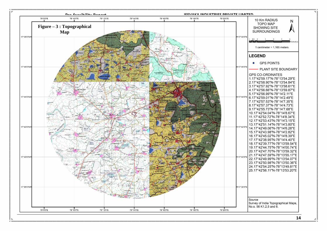
The coordinates of the Project site area
S.No. Latitude Longitude
1. 17°42'59.17" 78°13'54.29"
2. 17°42'58.90" 78°13'54.84"
3. 17°42'57.92" 78°13'58.61"
4. 17°42'56.66" 78°13'59.87"
5. 17°42'56.99" 78°14'2.11"
6. 17°42'59.01" 78°14'2.49"
7. 17°42'57.53" 78°14'7.35"
8. 17°42'57.37" 78°14'4.73"
9. 17°42'55.73" 78°14'7.68"
10. 17°42'54.04" 78°14'8.67"
11. 17°42'52.72" 78°14'8.34"
12. 17°42'53.43" 78°14'3.15"
13. 17°42'51.14" 78°14'3.80"
14. 17°42'49.06" 78°14'6.26"
15. 17°42'43.98" 78°14'2.82"
16. 17°42'45.02" 78°14'8.39"
17. 17°42'38.95" 78°14'4.40"
18. 17°42'39.77" 78°13'59.54"
19. 17°42'44.75" 78°14'00.74"
20. 17°42'47.70" 78°13'59.32"
21. 17°42'47.59" 78°13'55.17"
22. 17°42'49.99" 78°13'54.07"
23. 17°42'50.98" 78°13'50.36"
24. 17°42'54.25" 78°13'49.81"
25. 17°42'56.11" 78°13'53.20"
The entire project area will fall in the Survey of India topo sheet no. 56 K/2
The index map of the project site is shown in Figure - 1

Pre-feasibility Report
JEEVAKA INDUSTRIES PRIVATE LIMITED (Sponge Iron division)
12
Figure – 1 : Google Earth Map showing boundary of the project site

Pre-feasibility Report
JEEVAKA INDUSTRIES PRIVATE LIMITED (Sponge Iron division)
13
Plant site
Figure – 2 : General Location map
Pre-feasibility Report
JEEVAKA INDUSTRIES PRIVATE LIMITED (Sponge Iron division)
14
Figure – 3 : Topographical
Map

Pre-feasibility Report
JEEVAKA INDUSTRIES PRIVATE LIMITED (Sponge Iron division)
15
Figure – 4 : Plant Layout

Pre-feasibility Report
JEEVAKA INDUSTRIES PRIVATE LIMITED (Sponge Iron division)
16
3.3 Details of alternate sites considered:
No alternative site has been considered, as present proposal will be taken up partly in
the existing plant premises and partly in the additional land of 30.58 acres acquired
adjacent to the site.
3.4 Size or magnitude of operation:
The plant configuration & production capacity of proposed expansion of steel plant is as
follows
S.No. Name of the Product
Existing Proposed expansion
After proposed expansion
1. Sponge Iron 300 TPD (3x100 TPD)
200 TPD (2 x 100 TPD)
500 TPD (5 x 100 TPD)
2. Pellet Plant --- 600 TPD 600 TPD
3. M.S. Billets --- 1000 TPD
( 2 x 40 TPH
Induction furnace)
1000 TPD
4. TMT
Bars/Structural
Steels
-- 1000 TPD 1000 TPD
Ferro alloys (1 x 9 MVA furnace)
5. Ferro
Manganese
-- 100 TPD 100 TPD
6. Silico
Manganese
-- 70 TPD 70 TPD
7. Ferro Chrome -- 70 TPD 70 TPD
8. Ferro silicon -- 42 TPD 42 TPD
Power generation
9. Captive Power
plant
-- WHRB – 10 MW & FBC – 10 MW
WHRB – 10 MW & FBC – 10 MW

Pre-feasibility Report
JEEVAKA INDUSTRIES PRIVATE LIMITED (Sponge Iron division)
17
3.5 Manufacturing Process
3.5.1 Manufacturing Process Sponge Iron
DRI KLIN:
Major plant facilities
The major plant facilities for the sponge iron plant envisaged are as follows:
Day bins
Rotary kiln and cooler
Offgas system
Product processing and product storage.
Day bins
There shall be a day bin building to cater to raw material requirement of the kiln. The
day bin building will comprise of six bins, one for iron ore, two for feed coal, one for
limestone/dolomite and two bins for injection coal. These bins will generally have
storage of about one day's requirement of screened iron ore feed (5-20 mm), feed coal
(6-12 mm, 12 – 25 mm), limestone/dolomite (1-4 mm) and injection coal (3-6 mm. 6-
12mm). Weigh feeders will be provided to draw the required quantity of various
materials in proportion from the bins and the same will be conveyed to the kiln feed end
and discharge end.
Rotary kiln and cooler
The rotary kiln of 3.0 m dia. And 42 m length will be provided for reduction of iron ore
into sponge iron using non-coking coal as reductant. The kiln will be lined with abrasion
resistant refractory castable’s throughout its length with damps at feed end and
discharge end.
The rotary kiln will be supported on four piers. A slope of about 2.5% shall be
maintained. Then main drive of the kiln will be by two DC motors with thyristor control.
The speed of the kiln can be varied depending upon the operating conditions. The speed
of the kiln will be in the range of 0.25-0.75 rpm. The auxiliary drive of the kiln will be by
two AC motors.
The other main components of the kiln will be as given below:
Feed end and discharge end transition housing of welded steel construction with
refractory lining including feed chute.

Pre-feasibility Report
JEEVAKA INDUSTRIES PRIVATE LIMITED (Sponge Iron division)
18
Pneumatic cylinder actuated labyrinth air seal complete with auto lubricating system
at feed end and discharge end.
On board equipment like fans, manifolds, ports, slip ring, instrumentation etc.
Cooling fans at feed end and discharge end.
Feed end double pendulum valve & dust valves.
The kiln feed from the charging end will consist of sized iron ore (5-20mm), non-coking
coal (6-25 mm) and limestone/dolomite (1-4mm). Air will be supplied to the kiln through
shell mounted air fans. A part of the required coal (3-6mm, 6-12mm) shall be thrown
from kiln discharge end. The slinger coal will be withdrawn from the respective bins in
suitable proportion and pneumatically injected into the kiln. Necessary rotary feeder,
compressor, piping and valves will be provided.
In the kiln, the iron ore will be dried and heated to the reduction temperature of 1000 -
10500C. The iron oxide of the ore will be reduced to metallic iron by carbon monoxide
generated in the kiln from coal. The heat required for the reduction process will also be
supplied by the combustion of coal.
Thermocouples will be installed along the length of the kiln shell for measurement of
thermal profile of the kiln. The temperature will be controlled by regulating the amount
of combustion air admitted into the kiln through no. of ports with the help of fans
mounted on the kiln shell and by controlled coal slinging. The DC main drives provided
to rotate the kiln will have variable speed. Auxiliary drive is provided for slow rotation.
The reduced material from the kiln will be cooled indirectly in a rotary cooler by an
external water spray. The kiln will be provided with one rotary cooler. The rotary cooler
will be of 2.3 m dia. And 22 m length and will be supported on two piers with a slope of
about 2.5 %. The main drive and the auxiliary drive of the cooler will be by one no.
separate AC motor. The speed of the drive will be about 1 rpm. The cooler will be
provided with one plain riding ring and one thrust riding ring and will be provided with
two sets of support rollers at two piers and one set of hydraulic thrust rollers with
antifriction bearings. About 1 m end portion of the cooler acts as a screening section,
which separates all the accretions larger than 50 mm from the reduced material. These
lumps will be discharged separately via. Lump gate. Rest of the material will be
discharged on to the conveyor via double pendulum valve.
The other main components of the cooler will be the following.

Pre-feasibility Report
JEEVAKA INDUSTRIES PRIVATE LIMITED (Sponge Iron division)
19
Feed end housing (part of reactor to cooler transition) of welded steel
construction with refractory lining.
Cooler discharge end housing of welded steel construction.
Pneumatic cylinder actuated labyrinth air seal complete with auto lubricating
system at feed end and discharge end.
The cooler will be lined with refractory castable for about 4.0m length from the feed end.
Bypass arrangement will be provided at the discharge end of the cooler for emergency
discharge of materials. The cooled product will be conveyed to the product processing
building by a system of belt conveyors.
The cooling water will be collected in the trough below the cooler and sent to the cooling
tower for cooling. The cooled water will be re-circulated. Closed circuit cooling system
will be followed in the plant.
The rotating parts of the kiln and cooler will be sealed suitably against the stationary
parts at the connecting points to avoid leakage of dust laden gases.
Off gas system
The kiln shall have its separate off gas circuit. Hot waste gases leave the rotary kiln at
about 950 – 1000oC through kiln feed end housing, dust settling chamber and come to an
After Burning Chamber (ABC), where combustibles are burnt completely by supplying
excess air. The gases at about 900 - 950oC will then be led to a air cooled heat exchanger
and then through an Electro-static precipitator (ESP) before letting them out into the
atmosphere through ID fan and a combined stack of 70 m height ( with twin fuels).
Product processing and storage
There shall be one product processing unit for handling the cooler discharge. The
product containing sponge iron, char and spent lime, from the cooler discharge end will
be discharged to a set of conveyors and sent to the product processing building. The kiln-
cooler system shall have a separate surge bin of approx. 200 T capacity. Product from
surge bin can be withdrawn through vibrating feeder and fed to the product processing
building by conveyor. In the product processing building, the product will first be
screened in a double deck screen having 3mm and 20mm screens. +20mm material shall
be dumped as rejects. The screened product i.e., +3-20 mm and -3 mm fraction shall
separately be sent to the product storage separation. Sponge iron lump (3-20 mm) shall
be sent to the product storage building for storing in two no. of bunkers where three

Pre-feasibility Report
JEEVAKA INDUSTRIES PRIVATE LIMITED (Sponge Iron division)
20
days storage has been proposed. The sponge iron fines (-3 mm) will be stored in the fines
bunker in the product processing building itself where one day storage capacity will be
provided. The sponge iron lump & sponge iron fines will be further conveyed from the
respective bunkers by truck. The char/non-magnetics shall be stored in separate bins.
Char will be utilized for power generation in the FBC Boiler.

Pre-feasibility Report
JEEVAKA INDUSTRIES PRIVATE LIMITED (Sponge Iron division)
21
3.5.2 Manufacturing Process MS Billets
Steel Melt Shop (SMS) is crated to melt the Sponge Iron along with melting scrap and
fluxes to make pure liquid steel and than to mould it in required size billets. The shop
consists of following equipment and subassemblies:
Induction Furnaces: Induction Furnace is a device to melt the charge material using
electrical power. It consists of Crucible lined with water cooled induction coils, Electrical
system to give controlled power to induction coil, Hydraulic tilting system, Heat exchanger
to cool the circulating water, water softener for generating soft water, furnace
transformer, Power Factor improvement system and surge suppressor.
Ladles: Ladles are pots with refractory lining inside to withstand 1600 degC temperature. It
has side arms so that can be lifted with the help of crane. Ladles are used to stores the
liquid steel from Induction Furnace and take it for further processing. Ladles are with
bottom nozzle and pneumatically operated gate for discharge of liquid.
Ladle Refining Furnace (LRF): Ladle furnace is a mini electric arc furnace. It has three
carbon electrodes, roof to cover the ladle, and furnace transformer of suitable capacity.
The operation of electrodes, roof etc are controlled by hydraulic system. Ladle furnace is
used either to keep the liquid steel for sequence casting or for further refining of the
liquid steel to make better quality steel.
Cranes: Electric Over-head(EOT) cranes of various capacities are used to carry the
ladles/materials at different places. Cranes are used in Melting hall to charge melting
scrap, remove the ladles to the LRF, further to place it over the Tundish of the Continuous
Caster, to remove billets from the cooling bed and store at designated places, and also for
other petty use. Accordingly the sizes, capacity and numbers of cranes are decided.
Continuous Casting Machine (CCM) : CCM is used to continuously cast the liquid steel in
required cross section and in length. It consists of Tundish, Mould, Bow with Withdrawal
mechanism, straightening mechanism and cooling bed, hydraulic system for withdrawal
mechanism, water pumps and cooling towers for water spray on the withdrawn section as
well as on the cooling bed. Dummy bar is provided to start the casting. Tundish is a
rectangular vessel, lined with refractory and having discharge nozzle with pneumatically
operated gate. A stand is erected over it where the ladle is stationed for discharging the

Pre-feasibility Report
JEEVAKA INDUSTRIES PRIVATE LIMITED (Sponge Iron division)
22
liquid in it. Mould is of copper with water cooled jacked. Its cross-section in the bottom is
of the size of which billet is to be drawn. Initially the dummy for of the same size is kept
inserted. When the liquid steel is poured in the mould the dummy bar is drawn slowly, so
that the liquid steel in partially frozen state comes out of the mould. Water spray nozzles
are installed to spray water over the just drawn billet to cool it further and to harden the
skin of the drawn billet.
There will be 2 x 40 T Induction Furnaces. MS Billets will be produced in Continuous
Casting Machine.
3.5.3 Manufacturing Process TMT bars / Structural steels / Wire rod
Process description
Reheating furnace
A pusher type furnace has been envisaged for the heating of billets. The furnace will be
end charging and side discharging. It will have single row as well as double row charging
facility. The following size of billet will be fed to Billet Re-Heating Furnace.
100 mm x 100mm and 150 mm - 200 mm
The furnace will be heated with FO / Pulverized coal. The furnace combustion system
will comprise of air blowers, FO storage, supply and preheating system and other
associated facilities. The product of combustion will leave the furnace at charging end
and exhausted through underground flue tunnel and passed through a metallic tubular
recuperator before finally let off to a chimney of sufficient height after passing through
Bag filter. A set of instrument will be used for smooth operation of the furnace.
Bar and round mill
A cross country type mill has been envisaged for the plant. The stands have been
grouped into roughing, intermediate and finishing groups. Roughing group will have 4
(four) stands, intermediate group will have 8 (eight) stands and finishing mill will have 8
(eight) stands. Roughing group of stands will be driven by one motor. 4 nos. of
intermediate stands will be driven by two motors and balance 4 nos. will be driven by a
separate motor. Each stand of finishing group will be driven by single motor. Necessary
guides and troughs will be provided at entry and exit of mill stands.

Pre-feasibility Report
JEEVAKA INDUSTRIES PRIVATE LIMITED (Sponge Iron division)
23
One wire rod out let has been provided in the mill. The wire rod line will have 4 stand
block driven by a single motor through gear box. Coil forming and handling of coil is
provided.
Automated tilting, drop type tilter and feeding arrangement will be provided in roughing
group of stands. Repeaters have been provided in roughing / intermediate stands as
necessary.
Design provision has been made for introduction of slit rolling facility in future to roll 8
mm, 10 mm & 12 mm rebars in two strands. The rebars discharged from the mill will pass
through a water cooling system comprising cooling pipes with high pressure water
nozzles for rapid water quenching. At the cooling pipes the bar skin temperature will be
reduced to about 600oC. The core of the bar still remains hot. This entrapped heat
tempers the bar. This thermo-mechanical treatment of the bars increases tensile
strength without adversely effecting weldability and elongation properties. This process
eliminates requirement of cold twisting of bars for production of rebars.
A dividing shear, to cut the products to cooling bed length, will be located immediately
after the water cooling system. This shear will divide all products to cooling bed lengths.
Rake type cooling bed has been envisaged to receive the rolled product. Cooling bed will
be provided with incoming and outgoing roller tables. One cold shear has been provided
to cut the bars coming out of cooling bed into commercial length of 6 to 12 m. The bar
products will be formed into bundles and will be strapped by strapping machine
manually.
The finished products will be removed by overhead EOT crane and stored in the storage
area or dispatched through road vehicles. Rolling mill of 1000 TPD capacity is proposed in
the expansion project.

Pre-feasibility Report
JEEVAKA INDUSTRIES PRIVATE LIMITED (Sponge Iron division)
24

Pre-feasibility Report
JEEVAKA INDUSTRIES PRIVATE LIMITED (Sponge Iron division)
25
3.5.4 Ferro alloys
Ferroalloys are alloys of iron with chromium, manganese, silicon, or other
elements. Ferro Alloys will be produced by smelting the ore which contains
one or more of the said elements so as to impart its properties to the alloy.
Ferroalloys are essential additives in steel for imparting desired properties of steel
to suit varied applications.
It can be said that no steel can be made without use of one or more of the several
Ferro Alloys. Within each of these ferroalloy products there are variants whose
classification is based on the extent of carbon present in that alloy. The variants
observed under each of these product categories are explained in this section. Generally
Ferro Alloys are used as de oxidizers and alloy additives in the steel manufacturing.
THE PROCESS:
Ferro Alloys will be smelted at about 1350 – 1500 deg.C Temperature. This will be
achieved by a conventional, Open Submerged Electric Arc Furnace. The three carbon
Electrodes, partially submerged in the charge, are supported on hydraulic cylinders for
upward and down ward movements to maintain the desired electrical conditions.
The body of the furnace is cylindrical in shape, and is lined with firebricks, silicon carbide
bricks and carbon tamping paste. Three tap – holes are provided at 120 degree apart for
drawing out both the molten alloy and Slag. During the repair works one of the tap –
holes the other will function as stand by.
The weighed raw materials will be thoroughly mixed in the proper proportion before
charging into the furnace, through Skip, Telfer hoist and charging chutes. The charge will
be pushed near to electrodes on Furnace top by a Charging Stoker
As the charge enters the smelting zone, the alloy formed by chemical reactions of the
oxides and the reductants, will be heavy, and gradually settles at the bottom. At regular
intervals the furnace will be tapped. The tap hole will be opened by Oxygen lacing pipe
and after tapping is completed, it will be closed by clay plugs.
The liquid alloy and Slag will be collected in a Ladle and Slag will be over flowed to sand
beds. The metal being retained in the ladle having a Nozzle at bottom which allows metal
flows on to C.I. Pans. After solidification the cakes will be broken manually to required
lump size.

Pre-feasibility Report
JEEVAKA INDUSTRIES PRIVATE LIMITED (Sponge Iron division)
26
SILICO MANGANESE & FERRO MANGANESE PROCESS: Manganese ore is in the form of MnO, SiO2, FeO, Al2O3, MgO and other Oxides. MnO is
reduced to Mn and FeO is reduced to Fe taking Carbon from Coke / Coal and the product
is produced as Si Mn /Fe Mn. The other oxides are simultaneously removed as Slag along
with metal. The Slag and Metal are separated by virtue of its self-differential gravities
after collecting in the ladle. The ladle will have a nozzle in the bottom portion through
which the metal flows in to C.I. Pans.
Chemical Composition of Si Mn
Sl. No. Constituent Percentage
1. Mn 60 – 65%
2. Si + 15%
3. C 2% / 0.1% / 0.5%
4. S & P 0.03% Max
Chemical Composition of Fe Mn
Sl. No. Constituent Percentage
1 Mn 70 – 85%
2 Si + 1.5%
3 C 7 - 8% / 1.5% / 0.5%
4 S 0.05%
5 P 0.04%
FERRO SILICON PROCESS:
Ferro Silicon is a Slag less process. Quartz is the main raw material which contains 99% of
SiO2. Charcoal and a small percentage of Coal is used as reductants. Mill Scale / Iron
Ore is added to obtain Ferro Silicon. Fe O is reduced to Fe and Si O2 is reduced to Si
Combining with Carbon and produced as Fe Si.
Sl. No. Constituent Percentage
1 Si 70 – 75%
2 C 7 - 8%
3 S 0.05%
4 P 0.4%

Pre-feasibility Report
JEEVAKA INDUSTRIES PRIVATE LIMITED (Sponge Iron division)
27
FERRO CHROME It is produced by smelting Chrome Ore, reductant (coke) with fluxes in a submerged
electric arc furnace. In this process, Chromium Oxide & Iron Oxides are reduced to
Chromium & Iron and simultaneously combine with carbon to form alloy while other
constituents form slag. The molten alloy & slag are tapped out from time to time through
tap hole and collected in pans or ladles. Alloy is of higher specific gravity material than
slag. Hence, it segregates and remains at the bottom of the pan or the ladle where the
slag rises to top and over flows from it to other pan/ladle/ sand beds. If it is collected in
ladle, again it is to be casted to form cakes. When it is sufficiently cooled, cakes
are broken to required sizes and manually cleaned the slag if it is in surface of the
alloy pieces. Slag is a byproduct and reject material having very limited utility.
Chemical Composition of Fe Cr
Sl. No. Constituent Percentage
1 Cr 60%
2 C 8%
3 Si 3%
4 S 0.04%
5 P 0.04%

Pre-feasibility Report
JEEVAKA INDUSTRIES PRIVATE LIMITED (Sponge Iron division)
28

Pre-feasibility Report
JEEVAKA INDUSTRIES PRIVATE LIMITED (Sponge Iron division)
29
FERRO CHROME RECOVERY PLANT
Ferro chrome recovery process involves the following steps
I. Crushing & screening: In this slag is crushed to smaller size particles as close as
possible
II. Coarse jigging: In this particles having coarse fraction (approximately 32 to -3mm)
is separated through two stage air pulsated jig for recovery of metal.
III. Fine jigging: In this particles of fine fraction (-3mm) is separated through
diaphragm pulsed (through the bed’ jigs for recovery of metal.)
IV. The recovered metal will be reused in the process.

Pre-feasibility Report
JEEVAKA INDUSTRIES PRIVATE LIMITED (Sponge Iron division)
30
3.5.5 Pellet unit
The iron ore pelletization unit comprises of following sections:
1. Drying & Prepn. of Iron Ore Fines
2. Grinding
3. Mixing and Blending
4. Pelletization
5. Screening
6. Travel Grate Furnace
7. Rotary Kiln
8. Cooler
9. Stacking
10. Recovery of Dust and Spillage
a. Drying & Preparation of Iron ore Fines:
Generally Iron Ore Fines, Lime Stone and Dolomite fines available, contain more than
6-7% moisture and require drying before grinding. The drying is carried out in Rotary
Drum Dryer. The moisture content in the dry material is controlled. The low grade Iron
Ore Fines is feed in a screen for separation. Oversize / under size moves to the
primary grinding circuit.
b. Grinding
Iron Ore Fines, Dolomite and Lime Stone are mixed in required proportion and fed into
a Ball Mill. The fineness of the product is controlled as may be necessary for particular
ore and Pellet quality.
c. Mixing and Blending
Iron Ore powder blended with Bentonite and other binding materials in desired
proportion. Small quantity of water is added during blending operation. This raw mix
is ready for Pellet making and store in feed hopper.
d. Pelletization
Controlled quantity of raw mix is fed on disc Pelletizer. Some amount of water is
sprinkled for producing Pellets. These Pellets are passed through oversize and
undersize screens. Sized Pellets are then sent to sintering section.
Pre-feasibility Report
JEEVAKA INDUSTRIES PRIVATE LIMITED (Sponge Iron division)
31
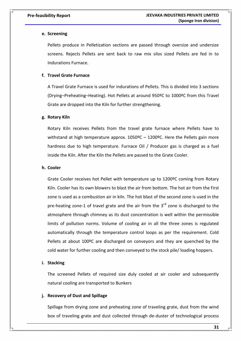
e. Screening
Pellets produce in Pelletization sections are passed through oversize and undersize
screens. Rejects Pellets are sent back to raw mix silos sized Pellets are fed in to
Indurations Furnace.
f. Travel Grate Furnace
A Travel Grate Furnace is used for indurations of Pellets. This is divided into 3 sections
(Drying–Preheating–Heating). Hot Pellets at around 950ºC to 1000ºC from this Travel
Grate are dropped into the Kiln for further strengthening.
g. Rotary Kiln
Rotary Kiln receives Pellets from the travel grate furnace where Pellets have to
withstand at high temperature approx. 1050ºC – 1200ºC. Here the Pellets gain more
hardness due to high temperature. Furnace Oil / Producer gas is charged as a fuel
inside the Kiln. After the Kiln the Pellets are passed to the Grate Cooler.
h. Cooler
Grate Cooler receives hot Pellet with temperature up to 1200ºC coming from Rotary
Kiln. Cooler has its own blowers to blast the air from bottom. The hot air from the first
zone is used as a combustion air in kiln. The hot blast of the second zone is used in the
pre-heating zone-1 of travel grate and the air from the 3rd zone is discharged to the
atmosphere through chimney as its dust concentration is well within the permissible
limits of pollution norms. Volume of cooling air in all the three zones is regulated
automatically through the temperature control loops as per the requirement. Cold
Pellets at about 100ºC are discharged on conveyors and they are quenched by the
cold water for further cooling and then conveyed to the stock pile/ loading hoppers.
i. Stacking
The screened Pellets of required size duly cooled at air cooler and subsequently
natural cooling are transported to Bunkers
j. Recovery of Dust and Spillage
Spillage from drying zone and preheating zone of traveling grate, dust from the wind
box of traveling grate and dust collected through de-duster of technological process

Pre-feasibility Report
JEEVAKA INDUSTRIES PRIVATE LIMITED (Sponge Iron division)
32
shall meet and will be sent to dust bin via belt conveyor, after they are ground
together with iron ore concentrate at grinding mill. Spillage (dry Pellets) produced at
the discharge end of traveling grate will be fed into the kiln from the feed chute of the
kiln feed end by bucket elevation. Almost all the dust and spillage are re-circulated
and recovered.
QUALITY OF PELLETS
Acidic and Basic Pellets: The pellets can be either acidic or basic in chemistry, depending
upon the composition of slag additive. Acid pellets have been used most extensively.
Although basic pellets are known to have advantages over acid pellets in terms of better
reducibility, softening and melting properties, their development has been slower. One
reason for such slow development is that the limestone and dolomite addition employed
requires so much heat for its calcination that the production capacity of the pelletizing
plant is reduced, compared with acidic grade pellets.
Typical analysis of both acidic and basic grade pellets is given in table below:
ANALYSIS OF VARIOUS QUALITIES OF PELLETS
Type Cao/SiO2 Fe, % SiO2, % MgO, %
Compression Strength, Kg/Pellet
Acidic Pellets < 0.15 64-67 2-4.5 <0.2 250-300
Basic Pellets ~0.8-1.0 62-64 2-4.5 1.3 200-250
Proposed Quality of Pellets Blast furnace charge can typically consist of about 20% pellets, 70% sinter and 10% lump
iron ore. Normally, in Indian Blast Furnaces, Pellets with CaO:SiO2 ratio in the range of
0.15 to 0.8 are being used. The targeted analysis of BF grade and DRI Grade pellets
proposed to be produced are given in table below:
QUALITY/ANALYSIS OF PELLET
Sl.No Property BF Grade DRI Grade
A. Chemical Quality
Fe 65% min 66.5% min
SiO2 + Al2O3 5% max 3.00% max
Al2O3 0.60% max 0.60% max
Na2O 0.05% max 0.05% max
K2O 0.05% max 0.05% max
TiO2 0.10% max 0.10% max
Mn 0.10% max 0.10% max

Pre-feasibility Report
JEEVAKA INDUSTRIES PRIVATE LIMITED (Sponge Iron division)
33
Sl.No Property BF Grade DRI Grade
P 0.04% max 0.04% max
S 0.02% max 0.02% max
V 0.05% max
Basicity (CaO+MgO/SiO2 + Al2O3)
0.40 0.50
B. Physical Quality
Size Distribution
+16mm 5% max 5% max
+16mm, +9mm 85% min 85% min
-9mm, +6.35mm 7% max 7% max
-5mm 5% max 5% max
Tumbler Index(+6.35mm) 94% min 94% min
Abrasion Index (+0.6mm) 5 % max 5 % max
C. Metallurgical Properties
Swelling Index 20% max 20% max
Compression Strength 250 Kg/Pellet min 250 Kg/Pellet min
Porosity 25% min 25% min
Reducibility 60% min 60% min
Metallization - 92% min
Fragmentation - 3.5% max
Attainment of these properties will be ensured by providing suitable raw materials/
beneficiated iron ore and also by adopting appropriate process parameters established
through test work before implementation of the project.

Pre-feasibility Report
JEEVAKA INDUSTRIES PRIVATE LIMITED (Sponge Iron division)
34

Pre-feasibility Report
JEEVAKA INDUSTRIES PRIVATE LIMITED (Sponge Iron division)
35
3.5.6 Power Generation
Its is proposed to install 10 MW WHRB & 10 MW AFBC based power plant in the
proposed expansion project to meet the power requirement for various processes of
integrated plant including auxillaries of power plant.
WHRB Power Plant
Production of sponge iron in DRI kiln generates huge quantities of hot flue gases carrying
considerable sensible heat. The energy content of these gases can effectively be used to
generate electric power as well as steam for meeting various process requirements. Thus
a WHRB (Waste Heat Recovery Boiler) power plant would be an ideally suited
proposition to effectively make use of this waste gas. This WHRB Power plant would not
only make the plant independent of external source of electric power to some extent but
would also result in energy conservation and environment protection.
Steam Turbo-generators (STGs) envisaged for the Power plant will be single cylinder,
multistage, extraction – cum – condensing type complete with condenser, air evacuation
system, 2 x 100% condensate extraction pumps, electronic governing system, lubricating
oil system, regenerative feed heating system etc. The turbine will be fed with steam
generated from HRSG in DR kiln. The STGs will be located in the machine hall of the
power plant.
5 x 10 TPH Boilers will be installed for 5 x 100 TPD DRI Kilns to generate 10 MW Power.
AFBC Power Plant
The unit will have One AFBC boiler (1 x 50 TPH Capacity) to generate 1 x 10 MW Power.
The boiler will be designed for continuous operation at Turbine Maximum Continuous
Rating (TMCR). A margin of 10% over TMCR will be taken into account to arrive at Boiler
rated capacity. The boiler will be natural circulation, circulating fluidized bed combustion,
two pass, non reheat, single drum, balanced draft, semi-outdoor type. The boiler will
have continuous evaporation rating of approx. 50 tonnes/hr. (BMCR will not be less than
110% of TMCR) with steam parameters at super heater outlet as 98 Kg/cm2 and 5400C (±
50oC). The feed water temperature at MCR at inlet to economizer is expected to be
around 2300C. Steam parameter are to be fine tuned at Boiler outlet based on actual
plant layout and piping arrangement. The boiler will be complete with ash /solid
separator, economizer, air heater, ducting, FD fans, ID fans and PA fans.
Air cooled condensers envisaged for Power plant to conserve water.

Pre-feasibility Report
JEEVAKA INDUSTRIES PRIVATE LIMITED (Sponge Iron division)
36
3.6 Raw material requirement, Transport etc.:
3.6.1 Raw Material Requirement and its sources (after proposed expansion)
Raw Material Quantity (TPD) Sources Mode of Transport
For DRI Kilns (Sponge Iron) – 500 TPD
Iron ore 800 Bellary
By rail & road (through covered trucks)
Coal Indian 650 Singareni colleries
By rail & road (through covered trucks)
Imported 500 Indonesia / South Africa / Australia
Through sea route, rail route & by road
Limestone 20 Local area
By road (through covered trucks)
For Pellet Plant – 600 TPD
Iron Ore Fines 600 In plant generation /
NMDC Limited
Through covered trucks by Road
Imported Coal / Indian coal 20 Indonesia / South Africa / Australia / Singareni colleries
Through sea route, rail route & by road
Bentonite 6.5 Gujarat
By road (through covered trucks)
Lime Stone 8 Kadapa / Kurnool
By road (through covered trucks)
Furnace oil 8 KL Local market Through road
For Induction Furnace (MS Billets) – 1000 TPD
Sponge Iron 900 In plant generation/Local
Market
By Conveyor
Scrap 200 Local area By road (through covered trucks)
Ferro Alloys 10 In plant generation/Local
area
By road (through covered trucks)
For Rolling Mill (TMT bars & Structural Steel) – 1000 TPD
M.S. Ingots / Steel billets 1,066 In plant generation
through conveyors
Furnace oil 35 HPCL/IOCL depots Tankers
or
Pulverized coal 100 Indian Coal / Imported
By road (through covered trucks)
Ferro alloys
Manganese ore 366 Imported / indigenous from
Through sea route, rail route & by road

Pre-feasibility Report
JEEVAKA INDUSTRIES PRIVATE LIMITED (Sponge Iron division)
37
Karnataka / Orissa / Madhya Pradesh / Andhra Pradesh
Quartz 130 Telangana By road (through covered trucks)
Chrome ore 161 Imported / indigenous from
Karnataka / Orissa / Madhya Pradesh / Andhra Pradesh
Through sea route, rail route & by road
Coke 101 Imported / Indigenous /
Singareni Colleries /
Through sea route, rail route & by road
Coal 133 Imported / Indigenous /
Singareni Colleries /
Through sea route, rail route & by road
Dolomite 68 Andhra pradesh By road (through covered trucks)
EC paste 8 Andhra pradesh By road (through covered trucks)
Ferro manganese slag 28 In plant generation
through covered conveyors
Magnesite 4.2 Andhra Pradesh By road (through covered trucks)
Mill scale 17 In plant Generation
through covered conveyors
For FBC Boiler [Power Generation 10 MW]
Dolochar 150 In plant generation
From Existing plant
through covered conveyors
Coal Indian 110 Singareni colleries
By rail & road (through covered trucks)
Imported 78 Indonesia / South Africa /
Australia
Through sea route / rail route / by road
3.6.2 Mode of Transport for Raw materials and finished products:
The aforesaid raw materials are transported through rail up to the nearest available rail
head and thereafter the same will be transported to the site through tarpaulin covered
trucks.

Pre-feasibility Report
JEEVAKA INDUSTRIES PRIVATE LIMITED (Sponge Iron division)
38
3.6.3 Market of Final Products:
It is proposed to install steel plant with special rolled products facility. As the steel/
power sector had huge demand and supply gap. Hence marketing of the product has no
problem.
3.7 Availability of water its source, Energy / power requirement and source: 3.7.1 Water Requirement and its sources:
Water required for the existing project is 27 KLD and same is being sourced through
Ground water resources
Water required for the expansion project will be 603 KLD and same will be sourced
through Ground water resources
Air cooled condensers will be provided for power plant to reduce the water
requirement
Water permission from State Ground Water Board has already been obtained for 640
KLD
Following is the breakup of water requirement:
S.No. Unit
Quantity in KLD
Existing Plant
Proposed Expansion
Total after Expansion
1. DRI Kilns (Sponge Iron) 15 10 25
2. Induction Furnace (MS Ingot/Billet)
-- 80 80
3. Rolling Mill Hot Rolled TMT / Structural / Cold Rolled Bars/Wire Rod)
-- 80 80
4. Ferro Alloy Plant FeSi / FeMn / SiMn / FeCr
-- 30 30
5. Pellet plant -- 180 180
6. Power Plant -- 215 215
7. Domestic 2 18 20
17 613 630

Pre-feasibility Report
JEEVAKA INDUSTRIES PRIVATE LIMITED (Sponge Iron division)
39
3.7.2 Sources of Energy/ Power and its sources:
Power required for the existing plant is being met from TSSPDCL. Power required for the
proposed expansion project will be met partly from proposed 20 MW power plant and
remaining from TSSPDCL.
The following will be the power consumption break-up for each unit
S.No. Plant Power Requirement
Existing Expansion After
Expansion
1. DRI 0.7 1.05 1.75
2. SMS 0 36 36
3. Rolling Mill 0 10 10
4. Ferro Alloys 0 9 9
5. Pellet plant 0 2.5 2.5
6. Power Plant – WHRB 0 2 2
7. Power plant – AFBC 0 2 2
Total 0.7 62.55 63.25
3.8 Generation and disposal of Wastes [Waste Water and Solid Wastes]:
3.8.1 Waste Water Generation:
There will be no effluent discharge in the DRI, SMS unit, Rolling mill & Pellet unit as
closed circuit cooling system will be adopted.
Effluent from power plant such as boiler blowdown, DM Plant regeneration. Initially the
acidic and alkaline effluent streams coming from cation and anion units of DM plant will
be neutralized in a neutralization tank. Service water will then pass through an Oil
Separator to remove the oil content in the effluent. The pH of Boiler blowdown will be
between 9.5 and 10.5. Hence this effluent stream shall be neutralized in a neutralization
tank before mixing with other effluent streams. All these effluent streams will be mixed
in a Central Monitoring Basin along with cooling tower blowdown. Treated effluent will
be used for ash conditioning, dust suppression and for greenbelt development.
The sanitary wastewater will be treated in septic tank followed by subsurface dispersion
trench. Hence there will not be any chance of contamination of water bodies due to
proposed project.

Pre-feasibility Report
JEEVAKA INDUSTRIES PRIVATE LIMITED (Sponge Iron division)
40
3.8.2 Solid Waste Generation and its disposal
The following will be the solid waste generation and disposal from the existing and
proposed expansion project
S.No Waste Quantity (TPD) Method of disposal
Existing Proposed Total
1. Ash from DRI 90 60 150 Is being given to Brick manufacturers. The same practice will be continued after expansion also.
2. Dolochar 90 60 150 Is being given to brick manufacturers. After proposed expansion it will be used as fuel in AFBC based power plant
3. Kiln Accretion Slag
2.7 1.8 4.5 Is being utilized in road construction and same practice will be continued after the proposed expansion also.
4. Wet Scraper Sludge
13.5 9 22.5 Is being given to brick manufacturer and same practice will be continued after the proposed expansion also.
5. SMS Slag -- 90 90 Slag from SMS will be crushed and iron will be recovered & remaining non –magnetic material being inert nature, will be used as sub base material in road construction / used for brick manufacturing / civil construction works like PCC and wall construction
6. Bag filter dust from SMS
-- 6.5 6.5 Will be being given brick manufacturers
7. Mill scales from Rolling Mill
-- 26 26 Will be used as raw material in pellet plant / SMS unit
8. Slag from SiMn
-- 84 84 Will be utilized in road construction / given to road contractor for road construction
9. Slag from FeMn
-- 80 80 Will be used in manufacture of Silico manganese as it contains high MnO2
10. Slag from FeCr -- 84 84 Will be further processed in Zigging plant for Chrome recovery and the non-chrome contents will be sent for land filling.
11. Ash from Power Plant
-- 155 155 Will be given to Brick manufacturers
12. Iron Ore Fines 15 10 25 Will be used in Pellet Manufacturing

Pre-feasibility Report
JEEVAKA INDUSTRIES PRIVATE LIMITED (Sponge Iron division)
41
Chapter – 4 SITE ANALYSIS
4.1 Connectivity
The Project site is well connected with Rail and Road connectivity. The nearest railway
station is Patancheru RS. The following table gives brief regarding connectivity of the
plant site:
Component Description
Road : SH # 17 (Sangareddy – Narsapur road) adjacent to the site
Rail : Patancheru RS (21.0 Kms)
Air port : Rajiv Gandhi International airport (55 Kms.)
4.2 Land Form, Land use and Land ownership
4.2.1 Land Form:
Present land is industrial land.
4.2.2 Land Use of the Project Site
Present land use is industrial land as existing plant is already under operation.
4.3 Topography
Topography of land is more or less flat terrain without much undulation.
4.4 Existing land use pattern:
4.4.1 Land use pattern of the Project site
Total project area is 85.58 acres (existing – 55 acres & additional – 30.58 acres).

Pre-feasibility Report
JEEVAKA INDUSTRIES PRIVATE LIMITED (Sponge Iron division)
42
4.4.2 Environmental Setting of the Project Site:
Below mentioned table gives brief regarding environmental setting of the project site:
S.No Particulars Distance from the site
1. National Park = Nil
2. Wild life sanctuaries = Nil
3. Reserve Forest = Narsapur RF – 3 Kms
4. Protected Forest = Nil
5. Eco Sensitive Areas = Nil
6. Water bodies = Small ponds exists within 10 Km radius
7. Costal Regulation Zone [CRZ] = Nil
8. Nearest Village = Avancha -0.50 kms.
9. Industrial Area = Nil
4.5 Existing Infrastructure
All required infrastructure is prevailing in the site.
4.6 Soil classification
The soils in the area are generally of clayey and lateritic. 4.7 Climatic data from secondary sources
Sangareddy district climate is classified as tropical. The summers here have a good deal
of rainfall, while the winters have very little. The climate here is classified as Aw by the
Köppen-Geiger system. The average temperature in Sangareddy is 26.3 °C. The average
annual rainfall is 861 mm. Precipitation is the lowest in January, with an average of 1
mm. Most of the precipitation here falls in July, averaging 228 mm.
At an average temperature of 32.2 °C, May is the hottest month of the year. December is
the coldest month, with temperatures averaging 21.9 °C. Between the driest and wettest
months, the difference in precipitation is 227 mm. Throughout the year, temperatures
vary by 10.3 °C.

Pre-feasibility Report
JEEVAKA INDUSTRIES PRIVATE LIMITED (Sponge Iron division)
43
Chapter – 5 PLANNING BRIEF
5.1 Planning Concept:
Jeevaka Industries Private Limited (JIPL) as a part of expansion of the existing steel plant,
envisage to produce the following product through different routes:
Unit : Description
DRI Kiln : Manufacturing of Sponge Iron using Iron ore, Coal and Dolomite
as raw materials
Pellet Plant Manufacturing of Iron Ore pellets from Iron Ore fines / Mill
scales, Bentonite, Lime Stone, Coal
Induction Furnace : Manufacturing of MS Billets using Sponge Iron, Scrap, Ferro
Alloys as raw materials.
TMT / Structural
steels
: Manufacturing of TMT bars / Structural steels using MS Billets /
Ingots as raw material
Ferro alloys : Ferro alloys will be manufactured using Manganese / Quartz /
Chrome ore as raw material
Power generation : Power geenration through WHRB by utilizing hot waste flue gases
from DRI kilns. Power generation through FBC boiler using coal,
Dolochar & Washery Rejects as fuel.
5.2 Population Projection:
There are no major human settlements in the vicinity of the project site. The manpower
requirement will be sourced from the local areas to the extent possible; hence not much
of settlement of outside people in the area. However population concentration may
increase around the project site due to increase in ancillary activities.
5.3 Land use planning:
Plant is located at Nasthipur Village, Hathnoora Mandal, Sangareddy District,
Telangana.
Total land in possession of management is 85.58 acres (existing 55 acres & additional
30.58 acres)

Pre-feasibility Report
JEEVAKA INDUSTRIES PRIVATE LIMITED (Sponge Iron division)
44
The proposed expansion project will be taken up partly in the existing plant premises
and partly in the additional land acquired.
The following is the land use statement
S.No. Item Area in acres
1. Built-up area 30.00
2. Storage area (raw material & solid waste) 6.00
3. Greenbelt area 30.00
4. Internal roads 7.50
5. Parking area 3.00
6. Open area 9.08
Total 85.58
5.4 Amenities/Facilities.
Facilities like canteen, rest room and indoor games facilities will be provided in the
proposed plant as basic facilities to workers. No other additional facilities are proposed.

Pre-feasibility Report
JEEVAKA INDUSTRIES PRIVATE LIMITED (Sponge Iron division)
45
Chapter – 6
PROPOSED INFRASTRUCTURE
6.0 Proposed Infrastructure
Total 85.58 acres of land is in possession of management (existing – 55 acres, additional
– 30.58 acres). Present use of land is Industrial land. The proposed expansion will be
carried out partly in the existing plant premises and partly in the additional land
premises.
6.1 Industrial Area (Processing Area)
The main plant area comprises of Kiln sheds, Furnace sheds, Rolling mill area, raw
material storage and product storage etc.
6.2 Residential Area (Non Processing Area)
No colonization is proposed; however facilities like canteen, rest room and indoor games
facilities have been provided in the existing plant premises.
6.3 Green Belt.
About 1/3rd of total land availability will be developed with greenbelt i.e 30 acres of land
will be allocated (including expansion).
Greenbelt development plan
Local DFO will be consulted in developing the green belt.
Greenbelt of 33% of the area will be developed in the plant premises as per CPCB
guidelines.
10 m wide greenbelt is being maintained all around the plant.
The tree species to be selected for the plantation are pollutant tolerant, fast
growing, wind firm, deep rooted. A three tier plantation is proposed comprising
of an outer most belt of taller trees which will act as barrier, middle core acting as
air cleaner and the innermost core which may be termed as absorptive layer
consisting of trees which are known to be particularly tolerant to pollutants.

Pre-feasibility Report
JEEVAKA INDUSTRIES PRIVATE LIMITED (Sponge Iron division)
46
6.4 Social Infrastructure.
Social infrastructure will be developed as per need based in the Villages of the vicinity of
the project.
6.5 Connectivity:
The proposed site is well connected with Rail and Road connectivity. The nearest railway
station is Patancheru RS. The following table gives brief regarding connectivity of the
proposed site:
Component Description
Road : SH # 17 (Sangareddy – Narsapur road) adjacent to the site
Rail : Patancheru RS – 21 Kms
Air port : Rajiv Gandhi International airport (55 Kms.)
6.6 Drinking Water Management:
Drinking water supply will be maintained at the proposed project site.
6.7 Sewerage System.
Domestic effluent collected through toilet blocks will be collected through well designed
sewer network and send to Septic tanks followed by sub surface dispersion trenchs.
6.8 Industrial Waste Management.
There will be no effluent discharge in the DRI, SMS, Pellet and Rolling mill units as closed
circuit cooling system will be adopted.
Effluent from power plant such as boiler blowdown, DM Plant regeneration. Initially the
acidic and alkaline effluent streams coming from cation and anion units of DM plant will
be neutralized in a neutralization tank. Service water will then pass through an Oil
Separator to remove the oil content in the effluent. The pH of Boiler blowdown will be
between 9.5 and 10.5. Hence this effluent stream shall be neutralized in a neutralization
tank before mixing with other effluent streams. All these effluent streams will be mixed
in a Central Monitoring Basin along with cooling tower blowdown. Treated effluent will
be used for ash conditioning, dust suppression and for greenbelt development.
The sanitary wastewater will be treated in septic tank followed by sub surface dispersion
trench. Hence there will not be any chance of contamination of water bodies due to
proposed project.

Pre-feasibility Report
JEEVAKA INDUSTRIES PRIVATE LIMITED (Sponge Iron division)
47
6.9 Solid Waste Management
The solid waste from sponge iron will be Dolochar, accretion slag, bagfilter dust, wet
scraper sludge. Dolochar will be used in the FBC power plant and others will be given to
brick manufacturers/ used in road construction
Slag from Induction furnace and Ferro alloys will be utilized in the road construction /
civil works / cement brick manufacturing.
6.10 Power requirement & its source
Power required for proposed expansion project will be sourced from proposed Captive
Power plant and TSSPDCL.
Chapter – 7
Rehabilitation and Resettlement Scheme
No rehabilitation and resettlement is required as there are no habitations in the in the
Project site.

Pre-feasibility Report
JEEVAKA INDUSTRIES PRIVATE LIMITED (Sponge Iron division)
48
Chapter – 8
Project Schedule & Cost Estimates 8.1 Likely date of start of construction:
Construction activity pertaining to unimplemented units will be started within 24 months
from the date of Environment Clearance.
8.2 Estimated project cost:
The estimated project cost for the proposed is about Rs. 292.5 crores. The following is
the break-up
S.No. Unit / Details Estimated Cost
(Rs. In Crores)
1. DRI Kilns [2 x 100 TPD] 24.00
2. SMS [2 x 40 T] 60.00
3. Rolling Mill [1000 TPD] 50.00
4. Ferro Alloys [1 x 9 MVA] 20.00
5. Pellet plant [600 TPD] 30.00
6. Power Plant [10 MW WHRB based & 10 MW FBC
based]
100.00
7. For Occupational Health & Risk Assessment 1.00
8. For Enterprise Social Commitment (ESC)
(2.5 % of the Project Cost)
7.50
Total 292.5

Pre-feasibility Report
JEEVAKA INDUSTRIES PRIVATE LIMITED (Sponge Iron division)
49
Chapter – 9
Analysis of proposal 9.1 Financial and social benefits:
With the implementation of the proposed expansion project, the socio-economic status
of the local people will improve substantially. The land rates in the area will improve in
the nearby areas due to the proposed activity. This will help in upliftment of the social
status of the people in the area. Educational institutions will also come-up and will lead
to improvement of educational status of the people in the area. Primary health centre
will also be developed by us and the medical facilities will certainly improve due to the
proposed project.
9.2 Socio-Economic Developmental Activities
The management is committed to uplift the standards of living of the villagers by
undertaking following activities / responsibilities as the part of Corporate Social
Responsibility.
Health & hygiene
Drinking water
Education for poor
Village roads
Lighting
HEALTH & HYGINE
Personal and domestic hygiene,
Maintaining clean neighborhood,
Weekly health camps offering free-check up & medicines
Ambulance services
Education & drug de-addiction, aids.
DRINKING WATER
Making drinking water available at centralized locations in the village,
SUPPORTING EDUCATION
Providing books to all poor children,
Conducting annual sports festival in the village schools,

Pre-feasibility Report
JEEVAKA INDUSTRIES PRIVATE LIMITED (Sponge Iron division)
50
Baseline Data Collection (March 2018 to May 2018)
We have commenced Baseline Data Collection from 1st March 2018.
Wind rose plotted as per nearest IMD data (Hyderabad region) for the period (1971 – 1999) for
March, April & May months

Pre-feasibility Report
JEEVAKA INDUSTRIES PRIVATE LIMITED (Sponge Iron division)
51
Ambient Air Quality Monitoring Stations
S.No. STATION DIRECTION DISTANCE
(in Kms.)
CRITERIA FOR SELECTION
1 Plant site --- --- Represent Plant Site (Core area)
2 Awancha E 0.5 Represents nearest habitation
3 Mangapur NW 0.6 Represents downwind direction and
Residential area
4 Ellapur SE 1.5 Represents Upwind direction
5 Ramachandrapuram NE 1.6 Represents Crosswind direction
6 Nastipur SW 1.3 Represents crosswind direction
7 Daulatabad W 1.8 Represents downwind direction
8 Narsapur NE 4.7 Represents highly populated and sensitive
area