jefferson county texas purchasing department d 4767 . appendix f: one-dimensional consolidation test...
TRANSCRIPT

IFB 15-016/JW – Addendum 1 Page 1 of 1
JEFFERSON COUNTY, TEXAS
PURCHASING DEPARTMENT 1001 Pearl Street – 3rd Floor
Beaumont, Texas 77701
409-835-8593
ADDENDUM TO IFB
IFB Number: IFB 15-016/JW
IFB Title: McFaddin National Wildlife Refuge Dune Restoration
IFB Due: 11:00 am CDT, Tuesday, June 30, 2015
Addendum No.: 1
Issued (Date): June 19, 2015
TO BIDDER: This Addendum is an integral part of the IFB package under consideration by you
as a Bidder in connection with the subject matter herein identified. Jefferson County deems all
sealed proposals to have been proffered in recognition and consideration of the entire IFB
package – including all addenda. For purposes of clarification, receipt of this present
Addendum by a Bidder should be evidenced by returning it (signed) as part of the Bidder’s
sealed proposal. If the Proposal has already been received by the Jefferson County Purchasing
Department, Bidder should return this addendum in a separate sealed envelope, clearly marked
with the IFB Title, IFB Number, and Opening Date and Time, as stated above.
Reason for Issuance of this addendum: Clarification Documents (Attached)
The information included herein is hereby incorporated into the documents of this present
Bid matter and supersedes any conflicting documents or portion thereof previously issued.
Receipt of this Addendum is hereby acknowledged by the undersigned Bidder:
ATTEST:
Authorized Signature (Bidder)
Witness
Title of Person Signing Above
Witness
Typed Name of Business or Individual
Approved by ____ Date: _________
Address

Page 1 of 3
Subject: Meeting Minutes Project No.: IFB 15-016/JW, McFaddin NWR Dune Ridge Restoration Meeting Location: Jefferson County Engineering Conference Room Date/Time: Tuesday, June 16, 2015 at 10:00AM Recorded By: S. Gonzales and V. Jones Meeting Purpose: Mandatory Pre-Bid Meeting Meeting Minutes:
1. Introductions and Sign-in a. See attached Attendance List for participants
2. Description of Project and Overview of Contract Documents
See Agenda for Project Summary a. Technical questions should be addressed to the Engineer, in writing, at
[email protected], by Tuesday June 23, 2015. Answers, in the form of addenda,
will be issued by the end of the day on Thursday, June 25, 2015.
b. Bid questions should be addressed to Jamey West in the County Purchasing Office at
c. Contractual questions regarding wages, classifications, Section 3 requirements, etc
should be addressed to Wesley McPhail, David J. Waxman, Inc. at
3. Bid Procedures: Overview a. Bids will be received in the new courthouse (Purchasing Department
1001 Pearl Street, 3rd Floor). Please plan accordingly, keep in mind the potential for
lines outside of security. The bid-opening will be held in the old courthouse
(Commissioners' Courtroom 1149 Pearl Street, 4th Floor). The contract will not be
awarded as a part of the bid opening.
b. Bid Form - Additive alternatives are not to be totaled cumulatively. Each alternate
grand total should include that additive alternate and the base bid.
c. Bids must be sealed and labeled on the outside of the package with IFB number and
name.
d. Addenda will be posted on the county website, and must be included in bid – check
website before sealing and submitting.
e. Lowest bidder will automatically be contacted to check for eligibility – NOTE: This does
not guarantee an award
f. Mobilization and Demobilization cannot exceed 10% of the base bid.
g. Contractual Information: i. HUB Standards – Note: TGLO requirements differ from federal requirements; be
certain to include all required paperwork, good faith efforts, etc. in bid package.

Page 2 of 3
ii. Winning bidder must register in SAM on the County website (see §1.20 of
General Terms for instructions)
iii. Wage Decision - Updates are typically made on Friday, it has not been updated
between bid notice and this meeting.
1. Wage Decision must be displayed on the jobsite with every page visible.
iv. Overtime - Overtime pay should begin when a worker reaches a total of 40
hours, this includes all projects or work completed within the week. Overtime
pay is equal to the base rate times 1.5 and fringes; fringes remain constant.
v. Compliance with Section 3 regulations are mandatory
vi. Subcontracts - If no section 3 contractors are available the contractor must
show evidence that a “good faith effort” was made to find a section 3
contractor. See www.hud.gov/Section3 for details.
1. Regarding Section 3 requirements, the term subcontractor does not
apply to survey crews, or soil testing contractor, or material suppliers.
(Note: HUB defines sub-contractors differently as typically all vendors)
vii. New work classifications must be approved by the D.O.L.
1. Often takes 30 days or more
2. Failure to comply could result in Labor Dept violations and restitutions
3. D.O.L. typically uses an average rate for these determinations
viii. Hiring (if needed)
1. 30% of new hires must be section 3 compliant
2. Forms are available for both individual workers, and businesses
3. TGLO requires all jobs be posted on State website (Work in Texas)
ix. Payroll is certified weekly; all submittals must be originals
4. Contractor Questions a. It was noted that boring logs B21 - B32 are not included in the bid package – these will
be included in Addendum #1 b. Project Schedule - The intent is to begin construction in a timely fashion following
contract award and execution, possibly August; bids are valid for 90 days per bid docs. c. Construction Sequence is typically berm footprint overburden removal to +2 ft NAVD
with material from borrow areas placed in template in approximately 1-ft lifts; this allows for de-watering and berm stability
d. Payment is based on the number of linear feet constructed, in place, with surveys required; acceptance surveys are typically on a monthly basis in support of pay applications
e. Overburden material from berm template is placed on the seaward side of the completed berm; overburden from the borrow areas is placed back into those areas unless otherwise noted.
f. Permitted Construction Corridor extends 20 feet landward of the borrow areas to 20 feet seaward of the berm footprint.
5. Project Site Visits
a. Access and Easements

Page 3 of 3
i. The refuge has an easement with Mr. Bill White, through coordination with the
refuge manager. Otherwise access is through the footprint of the project.
Access from the east is from Clam Lake Road, N to the GIWW, and then to Star
Lake and the existing levees. It takes approx. 45+ minutes to access the site
from HW 87 on the east side of the refuge. There is an existing road landward
of the beach at the western refuge entrance; the use of this road may or may
not be granted by the refuge staff. All transportation within the refuge should
be approved by Refuge staff (see pre-bid conference agenda for contact info).
ii. TxDot is aware of the potential desire to use their ROW adjacent to the SH
124/87 interchange as a secured contractor staging area.


JeffersonCounty
ChambersCounty
GalvestonCounty
McFaddin National Wildlife Refuge
WhitesLevee
PerkinsLevee
VASTAR
Jefferson CountyPhase II
Berm Project (5 miles)
Jefferson CountyPhase I
Berm Project (10 miles)
Jefferson CountyPhase III
Nourishment Project (20 miles)
Bill White's Fence Line
Date: March 25, 2015 LE Project No. 395-1003
905 Orleans Street Beaumont, TX 77701Tel: (409) 813-1862Fax: (409) 813-1916
Jefferson CountyMcFaddin NWR Dune Restoration
McFaddin Beach, Jefferson County, Texas
Exhibit AMcFaddin NWR Dune Restoration(2009 AERIAL, 2009/2010 LIDAR)
-
0 1 2 3 40.5
Miles
Fence
TPWD Berm Project
County Line
McFaddin NWR

GEOTECHNICAL ENGINEERING STUDY
BEACH RIDGE RESTORATION PHASE II
MCFADDIN NATIONAL WILDLIFE REFUGE
JEFFERSON COUNTY, TEXAS
Prepared for:
LJA Engineering, Inc.
5316 Highway 290 West, Suite 150
Austin, Texas 78735
Prepared by:
Tolunay-Wong Engineers, Inc.
2455 West Cardinal Drive, Suite A
Beaumont, Texas 77705
April 23, 2013
Project No. 12.23.220 / Report No. 57733


TWE Project No. 12.23.220 i Report No. 57733
TABLE OF CONTENTS
1 INTRODUCTION AND PROJECT DESCRIPTION 1-1
1.1 Introduction 1-1
1.2 Project Description 1-1
2 PURPOSE AND SCOPE OF SERVICES 2-1
3 FIELD PROGRAM 3-1
3.1 Soil Borings 3-1
3.2 Drilling Methods 3-1
3.3 Soil Sampling 3-1
3.4 Boring Logs 3-2
3.5 Groundwater Measurements 3-2
4 LABORATORY SERVICES 4-1
4.1 Laboratory Testing Program 4-1
5 SITE CONDITIONS 5-1
5.1 Site Descriptions and Surface Conditions 5-1
5.2 Subsurface Soil Stratigraphy and Properties 5-1
5.3 Groundwater Observations 5-2
6 GEOTECHNICAL RECOMMENDATIONS 6-1
6.1 Discussion 6-1
6.2 Settlement 6-1
6.3 Global Stability 6-2
6.4 Construction Considerations 6-3
7 LIMITATIONS AND DESIGN REVIEW 7-1
7.1 Limitations 7-1
7.2 Design Review 7-1
7.3 Construction Monitoring 7-1
7.4 Closing Remarks 7-1

TWE Project No. 12.23.220 ii Report No. 57733
TABLES AND APPENDICES
TABLES
Table 4-1 Laboratory Testing Program 4-1 Table 5-1 Groundwater Level Measurements 5-3 Table 6-1 Results of Settlement Analysis 6-1 Table 6-2 Results of Global Stability Analysis 6-3 APPENDICES
Appendix A: Project Information LJA Engineering, Inc. Appendix B: Soil Boring Location Plan Drawing No. 12.23.220-1 Appendix C: Logs of Project Borings and a Key to Symbols and Terms used on Boring Logs Appendix D: Undrained Shear Strength vs. Depth Borings B-21 through B-32 Appendix E: CU Triaxial Compression Test Reports ASTM D 4767 Appendix F: One-Dimensional Consolidation Test Reports ASTM D 2435 Appendix G: Soil Design Parameters Borings B-21 through B-32 Appendix H: Results of Global Stability Analysis

TWE Project No. 12.23.220 1-1 Report No. 57733
1 INTRODUCTION AND PROJECT DESCRIPTION
1.1 Introduction
This report presents the results of our geotechnical engineering study performed for Phase II of the proposed beach ridge restoration at the McFaddin National Wildlife Refuge in Jefferson County, Texas. Our geotechnical engineering study was conducted in accordance with TWE Proposal No. P12-B226 (Revision I) dated January 22, 2013 and authorized by Mr. Calvin T. Ladner, P.E. of LJA Engineering on January 24, 2013.
1.2 Project Description
The project includes the second phase of construction of an overwash protection berm along the upper Texas Gulf Coast at the McFaddin National Wildlife Refuge in Jefferson County, Texas. The protection berm is intended to keep seawater from routinely entering the interior of the refuge. TWE recently performed a geotechnical engineering study for Phase I of the project (TWE Project No. 12.23.220 / Report No. 53844) in which soil borings were performed to depths of 15-ft at approximately 0.5-mile intervals along the 10-mile berm alignment.
We were requested to perform a geotechnical engineering study for Phase II of the proposed beach ridge restoration to develop the geotechnical information needed to assist the Client in the design and construction of the new berm. Our geotechnical engineering study included the determination of global stability and settlement analyses of the proposed berm.

TWE Project No. 12.23.220 2-1 Report No. 57733
2 PURPOSE AND SCOPE OF SERVICES
The purposes of our geotechnical engineering study were to investigate the subsurface conditions within the project alignment and to provide geotechnical design and construction recommendations for the proposed berm.
Our scope of services performed for the project consisted of:
1. Performing twelve (12) soil borings to depths of 15-ft within the proposed berm alignment to determine subsurface soil and groundwater conditions;
2. Performing geotechnical laboratory tests on recovered soil samples to evaluate the physical and engineering properties of the strata encountered;
3. Providing geotechnical design recommendations including suitability of proposed borrow materials, global stability and settlement estimates of the proposed new berm; and,
4. Providing geotechnical construction recommendations including site and subgrade preparation, excavation considerations, fill and backfill placement, compaction requirements and overall quality control testing, inspection and monitoring services for the proposed protection berm.
Our scope of services did not include any environmental assessments for the presence or absence of wetlands or of hazardous or toxic materials within or on the soil, air or water within the project alignment. Any statements in this report or on the boring logs regarding odors, colors or unusual or suspicious items or conditions are strictly for the information of the Client. A geological fault study was also beyond the scope of our services associated with our geotechnical engineering study.
TWE Project No. 12.23.220 3-1 Report No. 57733
3 FIELD PROGRAM
3.1 Soil Borings
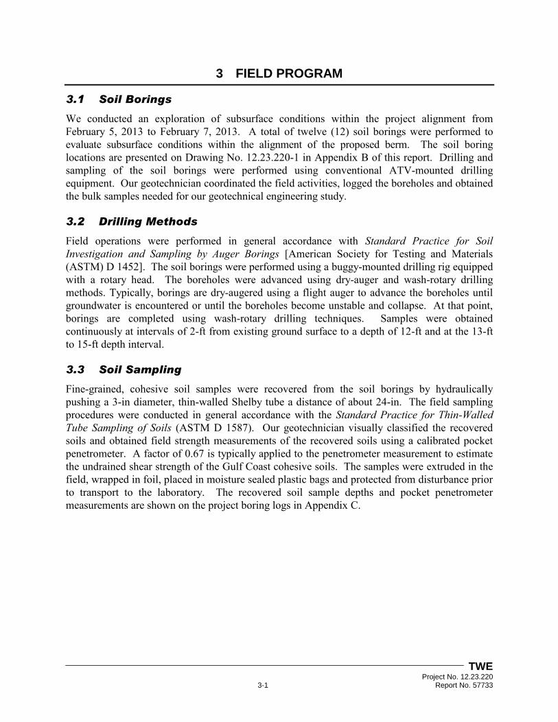
We conducted an exploration of subsurface conditions within the project alignment from February 5, 2013 to February 7, 2013. A total of twelve (12) soil borings were performed to evaluate subsurface conditions within the alignment of the proposed berm. The soil boring locations are presented on Drawing No. 12.23.220-1 in Appendix B of this report. Drilling and sampling of the soil borings were performed using conventional ATV-mounted drilling equipment. Our geotechnician coordinated the field activities, logged the boreholes and obtained the bulk samples needed for our geotechnical engineering study.
3.2 Drilling Methods
Field operations were performed in general accordance with Standard Practice for Soil Investigation and Sampling by Auger Borings [American Society for Testing and Materials (ASTM) D 1452]. The soil borings were performed using a buggy-mounted drilling rig equipped with a rotary head. The boreholes were advanced using dry-auger and wash-rotary drilling methods. Typically, borings are dry-augered using a flight auger to advance the boreholes until groundwater is encountered or until the boreholes become unstable and collapse. At that point, borings are completed using wash-rotary drilling techniques. Samples were obtained continuously at intervals of 2-ft from existing ground surface to a depth of 12-ft and at the 13-ft to 15-ft depth interval.
3.3 Soil Sampling
Fine-grained, cohesive soil samples were recovered from the soil borings by hydraulically pushing a 3-in diameter, thin-walled Shelby tube a distance of about 24-in. The field sampling procedures were conducted in general accordance with the Standard Practice for Thin-Walled Tube Sampling of Soils (ASTM D 1587). Our geotechnician visually classified the recovered soils and obtained field strength measurements of the recovered soils using a calibrated pocket penetrometer. A factor of 0.67 is typically applied to the penetrometer measurement to estimate the undrained shear strength of the Gulf Coast cohesive soils. The samples were extruded in the field, wrapped in foil, placed in moisture sealed plastic bags and protected from disturbance prior to transport to the laboratory. The recovered soil sample depths and pocket penetrometer measurements are shown on the project boring logs in Appendix C.

TWE Project No. 12.23.220 3-2 Report No. 57733
3.4 Boring Logs
Our interpretations of general subsurface conditions at the boring locations are included on the project boring logs. The interpretations of the soil types throughout the boring depths and the locations of strata changes were based on visual classifications during field sampling and laboratory testing using Standard Practice for Classification of Soils for Engineering Purposes (Unified Soil Classification System) [ASTM D 2487] and Standard Practice for Description and Identification of Soils (Visual-Manual Procedure) [ASTM D 2488]. The boring logs include the type and interval depth for each sample along with the corresponding pocket penetrometer readings for cohesive soils. The project boring logs and a key to the terms and symbols used on boring logs are presented in Appendix C.
3.5 Groundwater Measurements
Groundwater level measurements were attempted in the open boreholes during dry-auger drilling. Water level readings were attempted when groundwater was first encountered and at five (5) minute intervals over a fifteen (15) minute time period. Groundwater observations are summarized in Section 5.3 of this report entitled “Groundwater Observations.”
TWE Project No. 12.23.220 4-1 Report No. 57733
4 LABORATORY SERVICES
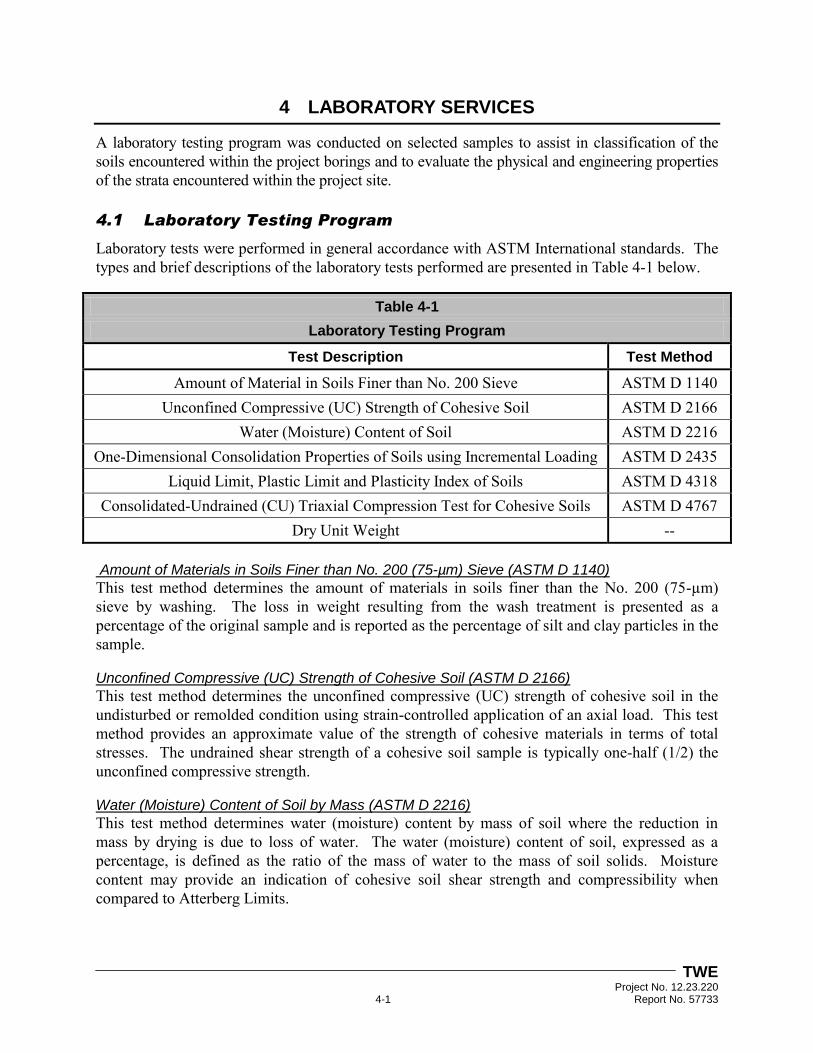
A laboratory testing program was conducted on selected samples to assist in classification of the soils encountered within the project borings and to evaluate the physical and engineering properties of the strata encountered within the project site. 4.1 Laboratory Testing Program
Laboratory tests were performed in general accordance with ASTM International standards. The types and brief descriptions of the laboratory tests performed are presented in Table 4-1 below.
Table 4-1
Laboratory Testing Program
Test Description Test Method
Amount of Material in Soils Finer than No. 200 Sieve ASTM D 1140 Unconfined Compressive (UC) Strength of Cohesive Soil ASTM D 2166
Water (Moisture) Content of Soil ASTM D 2216 One-Dimensional Consolidation Properties of Soils using Incremental Loading ASTM D 2435
Liquid Limit, Plastic Limit and Plasticity Index of Soils ASTM D 4318 Consolidated-Undrained (CU) Triaxial Compression Test for Cohesive Soils ASTM D 4767
Dry Unit Weight -- Amount of Materials in Soils Finer than No. 200 (75-µm) Sieve (ASTM D 1140)
This test method determines the amount of materials in soils finer than the No. 200 (75-µm) sieve by washing. The loss in weight resulting from the wash treatment is presented as a percentage of the original sample and is reported as the percentage of silt and clay particles in the sample.
Unconfined Compressive (UC) Strength of Cohesive Soil (ASTM D 2166)
This test method determines the unconfined compressive (UC) strength of cohesive soil in the undisturbed or remolded condition using strain-controlled application of an axial load. This test method provides an approximate value of the strength of cohesive materials in terms of total stresses. The undrained shear strength of a cohesive soil sample is typically one-half (1/2) the unconfined compressive strength.
Water (Moisture) Content of Soil by Mass (ASTM D 2216)
This test method determines water (moisture) content by mass of soil where the reduction in mass by drying is due to loss of water. The water (moisture) content of soil, expressed as a percentage, is defined as the ratio of the mass of water to the mass of soil solids. Moisture content may provide an indication of cohesive soil shear strength and compressibility when compared to Atterberg Limits.

TWE Project No. 12.23.220 4-2 Report No. 57733
One-Dimensional Consolidation of Soils Using Incremental Loading (ASTM D 2435)
This test method determines the magnitude and rate of consolidation (CON) of soil when it is restrained laterally and drained axially while subject to incrementally applied controlled-stress loading. Results of consolidation testing provide important information regarding the stress-soil history and soil compressibility. During consolidation testing, the soil sample is initially set in a consolidation cell followed by a saturation period in which swelling is prevented by controlled loading. Once swelling ceases, the consolidation test is performed by adding predetermined incremental loads up to a percent strain of about 20% of the loading frame capacity. Once this capacity is met, the final load is removed to observe the final rebound. Consolidation testing includes an unload-reload cycle which reduces the effect of soil disturbance from sampling.
Liquid Limit, Plastic Limit and Plasticity Index of Soils (ASTM D 4318)
This test method determines the liquid limit, plastic limit and the plasticity index of soils. These tests, also known as Atterberg limits, are used from soil classification purposes. They also provide an indication of the volume change potential of a soil when considered in conjunction with the natural moisture content. The liquid limit and plastic limit establish boundaries of consistency for plastic soils. The plasticity index is the difference between the liquid limit and plastic limit.
Consolidated-Undrained Triaxial Compression Test on Cohesive Soils (ASTM D 4767)
This test method determines the strength and stress-strain relationships of a cylindrical specimen of either undisturbed or remolded cohesive soil. Specimens are subjected to a confining fluid pressure in a triaxial chamber. Drainage of the specimen is not permitted during the test. The specimen is sheared in compression without drainage at a constant rate of axial deformation (strain-controlled). The consolidated-undrained (CU) triaxial shear strength of cohesive soils is applicable to situations where soils that have been fully-consolidated under one (1) set of stresses are subjected to a change in stress without time for further consolidation to take place (undrained condition).
Dry Unit Weight of Soils
This test method determines the weight per unit volume of soil, excluding water. Dry unit weight is used to relate the compactness of soils to volume change and stress-strain tendencies of soils when subjected to external loadings.
Soil properties including moisture content, unit weight, Atterberg limits, grain size distribution, penetration resistance and compressive strength are presented on the project boring logs in Appendix C. Reports of CU triaxial compression test results are provided in Appendix E. One-dimensional consolidation test results are included in Appendix F.

TWE Project No. 12.23.220 5-1 Report No. 57733
5 SITE CONDITIONS
Our interpretations of subsurface conditions within the project alignment are based on information obtained at the soil boring locations only. This information has been used as the basis for our conclusions and recommendations included in this report. Subsurface conditions may vary at areas not explored by the soil borings. Significant variations at areas not explored will require reassessment of our recommendations.
5.1 Site Descriptions and Surface Conditions
The project site is located at the McFaddin National Wildlife Refuge in Jefferson County, Texas. Additional information regarding the project site is included in Section 1.2 and Appendix A of this report. An aerial image of the project alignment is included in Drawing No. 12.23.220-1 in Appendix B. Surface conditions within the project alignment consisted of thick pasture grasses, dense weeds, ponded water and some areas that were soft and weak. Conventional ATV-mounted drilling equipment and all-wheel drive vehicles were required to access the soil boring locations.
5.2 Subsurface Soil Stratigraphy and Properties
Soil Borings B-21 through B-28, B-30 to B-32
The subsurface profile encountered in project borings B-21 through B-28, and B-30 to B-32 consisted of alternating cohesive clay soils (CL and CH) from existing ground surface to the boring completion depths of 15-ft. A semi-cohesionless sand soil was encountered in project boring B-25 from existing ground surface to a depth of 4-ft and from a depth of 10-ft to 13-ft below ground surface. Ferrous nodules, calcareous nodules and sand pockets were also observed within the subsurface soil matrix of the project borings.
Results of Atterberg limits tests on selected samples of the cohesive clay soils recovered from project borings B-21 through B-28, and B-30 to B-32 indicate liquid limits ranging from 44 to 73 with corresponding plasticity indices ranging from 29 to 54. In-situ moisture contents of the samples ranged from 24% to 51%. The amount of material passing the No. 200 sieve ranged from 72% to 97%.
Undrained shear strengths derived from pocket penetrometer measurements ranged consistently from 0.17-tsf to 0.83-tsf. Undrained shear strengths determined from laboratory UC tests performed on selected samples ranged from 0.06-tsf to 0.51-tsf with corresponding total unit weights ranging from 106-pcf to 122-pcf. Undrained shear strengths determined from laboratory torvane tests performed on selected samples ranged from 0.15-tsf to 0.40-tsf. Based on the above undrained shear strength data, the cohesive soils encountered within project borings B-21 through B-28, B-30 to B-32 are inferred to have very soft to hard, but typically soft to firm consistencies.

TWE Project No. 12.23.220 5-2 Report No. 57733
Soil Boring B-29
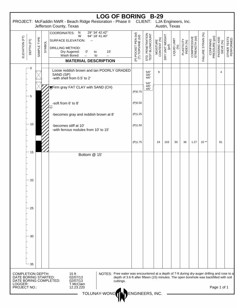
The subsurface profile encountered in project boring B-29 consisted of a surficial layer of poorly graded sand (SP) from existing ground surface to a depth of 3-ft underlain by a fat clay with sand (CH) soil to the boring completion depth of 15-ft. Ferrous nodules, were also observed within the cohesive soil matrix encountered in the project boring.
Results of Atterberg limits tests on a selected sample of the cohesive soils recovered from the project boring indicate liquid limit of 50 with a corresponding plasticity index of 36. An in-situ moisture content of the samples was 24%. The amount of material passing the No. 200 sieve was 81%.
Undrained shear strengths derived from pocket penetrometer measurements ranged from 0.17-tsf to 0.58-tsf. Undrained shear strengths determined from laboratory UC tests performed on a selected sample was 0.64-tsf with a corresponding total unit weight of 128-pcf. Based on the above undrained shear strength data, the cohesive soils encountered within the project boring are inferred to have soft to stiff consistencies.
We recorded SPT N-values from cohesionless soil strata encountered ranging from to 7 to 8 blows per foot indicating loose relative densities of these strata. The in-situ moisture content from testing a selected sample was 9%. The amount of materials finer than the No. 200 sieve on selected cohesionless soil strata was 4%.
Soil properties including moisture content, unit weight, Atterberg limits, grain size distribution, penetration resistance and compressive strength are presented on the project boring logs in Appendix C. Reports of CU triaxial compression test results are provided in Appendix E. One-dimensional consolidation test results are included in Appendix F.
5.3 Groundwater Observations
Groundwater measurements obtained from the project borings during dry-auger drilling are presented in Table 5-1 on the following page.

TWE Project No. 12.23.220 5-3 Report No. 57733
Table 5-1
Groundwater Level Measurements
Groundwater Level Measurements
Soil Boring
Identification
Completion
Depth During Dry-Auger Drilling
Depth Observed after
Fifteen (15) Minutes
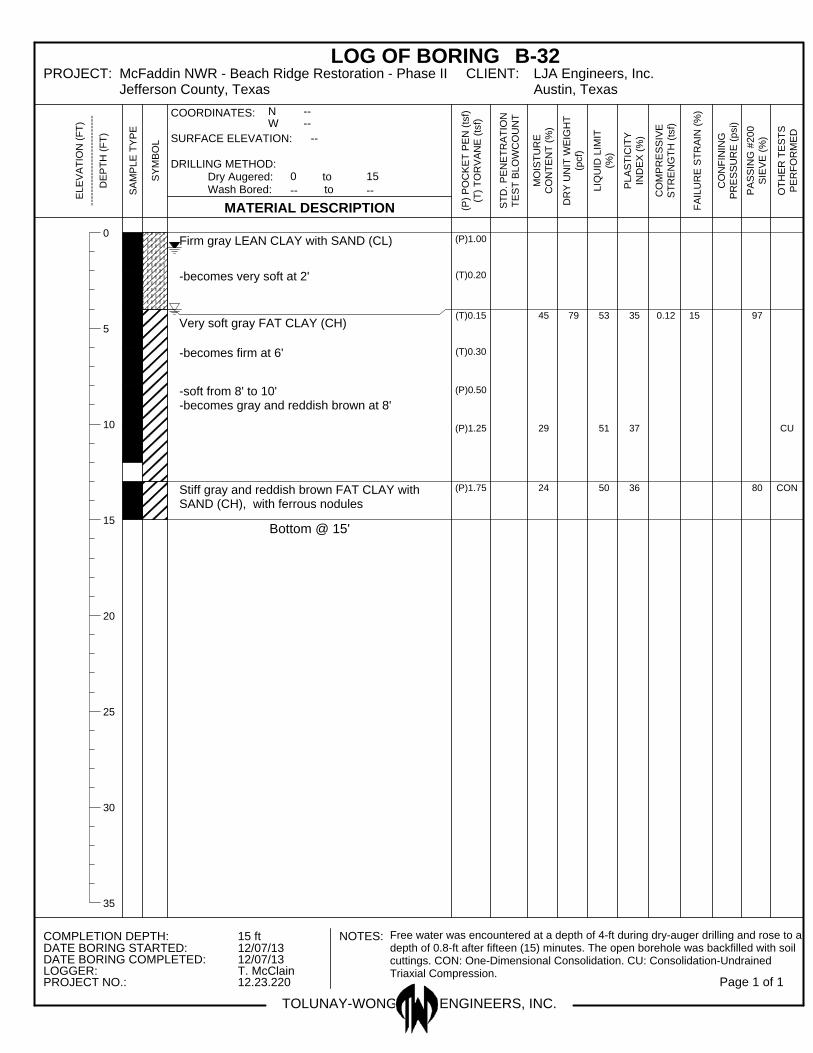
B-21 15-ft 5.0-ft 2.2-ft B-22 15-ft 3.0-ft 1.2-ft B-23 15-ft 5.0-ft 2.6-ft B-24 15-ft 4.0-ft 2.1-ft B-25 15-ft 4.5-ft 2.8-ft B-26 15-ft 4.0-ft 0.8-ft B-27 15-ft Free water was not encountered during dry-auger drilling B-28 15-ft 6.0-ft 0.3-ft B-29 15-ft 7.0-ft 3.6-ft B-30 15-ft 4.0-ft 0.4-ft B-31 15-ft 3.0-ft 0.4-ft B-32 15-ft 4.0-ft 0.8-ft
Groundwater levels may fluctuate with climatic and seasonal variations and should be verified before construction. Accurate determination of static groundwater levels throughout the project alignment could be made with standpipe piezometers. Installation of standpipe piezometers to evaluate long-term groundwater conditions within the project alignment was not included in our scope of services.

TWE Project No. 12.23.220 6-1 Report No. 57733
6 GEOTECHNICAL RECOMMENDATIONS
6.1 Discussion
We understand that the berm will be constructed to an elevation of El +6-ft. According to drawings provided by the Client in Appendix A, we understand natural ground elevation prior to berm construction is at approximately El +2.0-ft. Therefore, the new berm is estimated to have a height of approximately 4-ft above natural ground.
The footprint addressing the critical need area of the protection berm is about 6.0-miles in length with a 12-ft wide crest and 1(V):3(H) side slopes. We understand that a borrow area will be established landward of the proposed berm. Borrow areas will run parallel to the new berm alignment a minimum of 50-ft beyond the toe of the slope. Soils from the borrow areas will be excavated and placed as fill within the limits of the new berm alignment. Based on discussions with the Client, the fill will be placed in layers and semi-compacted.
Our geotechnical design recommendations regarding settlement and global stability of the proposed berm using semi-compacted fill obtained from the borrow area are provided in Sections 6.2 and 6.3 below, respectively.
6.2 Settlement
Settlement analysis was performed using the UniSettle computer program (Version 4) distributed by UniSoft Ltd. The program was developed by Pierre Goudreault and Bengt Fellenius and uses the Janbu Tangent Modulus approach (Janbu 1998) to calculate consolidation and elastic settlements.
In our analysis, we divided the project borings into two (2) groups because of similarities in subsurface profiles within each group. We calculated total long-term settlements at the center and edge of the proposed protection berm for berm heights of 4-ft, 5-ft and 6-ft for each group. Settlements calculated for each berm height are shown in Table 6-1 below.
Table 6-1
Results of Settlement Analysis
Berm Height
4-ft 5-ft 6-ft
Center Edge Center Edge Center Edge
Borings B-21
Through B-28,
B-30 to B-32
0.5-in - 1.0-in 0.5-in - 1.0-in 1.0-in - 1.5-in 0.5-in - 1.0-in 1.5-in - 2.0-in 0.5-in - 1-in
Boring B-29 0.5-in - 1.0-in 0.5-in - 1.0-in 1.0-in - 1.5-in 0.5-in - 1.0-in 1.0-in - 1.5-in 0.5-in - 1-in
TWE Project No. 12.23.220 6-2 Report No. 57733
Based on the results of our analysis, it appears that long-term settlements for a berm height of 4.0-ft will be on the order of 1-in or less. Based on the magnitude of the estimated settlements, consideration could be given to constructing the proposed berm to at least 0.25-ft higher than design crest elevation to compensate for long-term settlement and construction tolerances. It should be noted that the computed settlement is based on compressibility parameters derived from laboratory one-dimensional consolidation test data and empirical relationships with soil classification. We expect that actual settlements could be within ±30% of the calculated values.
6.3 Global Stability
Based on the cross section provided by the Client, we understand the proposed protection berm will have a crest width of 12-ft with 1(V):3(H) side slopes. Using this information and a 4.5-ft berm height, we have performed slope stability analysis which considers that the in-situ borrow materials will be used as semi-compacted fill for new berm construction. The following sections present our global stability analysis in further detail.
6.3.1 Loading Conditions
Short-term and long-term analysis conditions were considered in our stability analysis of the proposed protection berm. The short-term case considers undrained parameters in the fine-grained, cohesive clay soils. The minimum recommended factor of safety for short-term loading conditions is 1.3. The long-term case considers conditions that will exist for a time period after construction needed for drained soil strength conditions to develop under sustained loading conditions. Analysis of long-term conditions is performed using drained soil parameters for the cohesive clay soils. The minimum recommended factor of safety for long-term loading conditions is 1.5.
6.3.2 Soil Parameters
Soil parameters used in our stability analysis were based on the information derived from the project borings and our experience with similar subsurface conditions. Undrained shear strength (short-term) values for the cohesive soils encountered were based on field and laboratory strength test results. The angle of internal friction used for cohesive soils under undrained conditions was taken as zero (also known as “ = 0 condition”). Drained shear strength (long-term) values and angles of internal friction were estimated primarily from results of CU testing performed in our laboratory and empirical correlations with plasticity indices. The soil design parameters used in our analysis are presented in Appendix G of this report.
6.3.3 Evaluation
Global stability analyses were performed to evaluate the stability of the proposed protection berm and the respective material types derived from project borings B-21 through B-32. Our stability analyses were performed using the computer program SLIDE Version 6.0 as developed by Rocscience Inc. and the Bishop limit equilibrium procedure implemented within the program. The SLIDE computer program searches for the critical slope failure plane and computes the minimum safety factor for a given slope geometry and subsurface soil and groundwater profile. The computed factor of safety is the ratio of forces resisting movement to the forces causing movement.
TWE Project No. 12.23.220 6-3 Report No. 57733
6.3.4 Conclusion
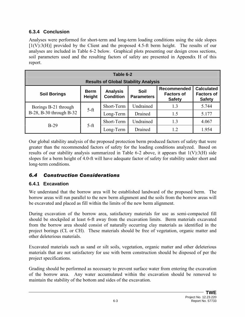
Analyses were performed for short-term and long-term loading conditions using the side slopes [1(V):3(H)] provided by the Client and the proposed 4.5-ft berm height. The results of our analyses are included in Table 6-2 below. Graphical plots presenting our design cross sections, soil parameters used and the resulting factors of safety are presented in Appendix H of this report.
Table 6-2
Results of Global Stability Analysis
Soil Borings Berm
Height
Analysis
Condition
Soil
Parameters
Recommended
Factors of
Safety
Calculated
Factors of
Safety
Borings B-21 through B-28, B-30 through B-32 5-ft
Short-Term Undrained 1.3 5.744 Long-Term Drained 1.5 5.177
B-29 5-ft Short-Term Undrained 1.3 4.067
Long-Term Drained 1.2 1.954
Our global stability analysis of the proposed protection berm produced factors of safety that were greater than the recommended factors of safety for the loading conditions analyzed. Based on results of our stability analysis summarized in Table 6-2 above, it appears that 1(V):3(H) side slopes for a berm height of 4.0-ft will have adequate factor of safety for stability under short and long-term conditions.
6.4 Construction Considerations
6.4.1 Excavation
We understand that the borrow area will be established landward of the proposed berm. The borrow areas will run parallel to the new berm alignment and the soils from the borrow areas will be excavated and placed as fill within the limits of the new berm alignment.
During excavation of the borrow area, satisfactory materials for use as semi-compacted fill should be stockpiled at least 6-ft away from the excavation limits. Berm materials excavated from the borrow area should consist of naturally occurring clay materials as identified in the project borings (CL or CH). These materials should be free of vegetation, organic matter and other deleterious materials.
Excavated materials such as sand or silt soils, vegetation, organic matter and other deleterious materials that are not satisfactory for use with berm construction should be disposed of per the project specifications.
Grading should be performed as necessary to prevent surface water from entering the excavation of the borrow area. Any water accumulated within the excavation should be removed to maintain the stability of the bottom and sides of the excavation.

TWE Project No. 12.23.220 6-4 Report No. 57733
6.4.2 Semi-Compacted Fill
The alignment designated for new berm construction should be stripped of all surface vegetation, organic matter, debris and other deleterious materials. Once stripping is complete and prior to fill placement, the surface should be scarified to a depth of 6-in. After the foundation soils are scarified, the subgrade should be compacted in accordance with the following sections of this report. Scarification should be performed parallel to the centerline of the proposed berm at least 200-ft, but no greater than 500-ft, in advance of berm construction.
The proposed berm should be constructed to the required design section as specified by the Engineer using sufficient amounts of satisfactory materials obtained from the parallel borrow area. The fill material should be placed and spread in maximum 12-in thick layers prior to compaction.
Moisture Content
The moisture content of the borrow fill material should be controlled during construction. We recommend that moisture contents be conditioned to between 18% and 28% for lean clay (CL) soils and 20% to 37% for fat clay (CH) soils when placed within the new berm alignment. We also recommend that a minimum of one (1) moisture content test be performed for every lift of berm construction.
Compaction should not begin until moisture content tests are performed and the moisture content is within the specified ranges. Wet material should be processed by stockpiling, disking and harrowing until the moisture content is reduced sufficiently. If the borrow material is too dry, pre-wetting will be required prior to compacting.
Compaction
When the moisture content and conditions of the fill layers are satisfactory, each layer should be compacted using a crawler-type tractor with a ground pressure of 7-psi or greater. Three (3) complete passes over each layer should be performed after spreading is completed. Each pass should consist of one (1) complete coverage of the surface of a layer by the treads of the tractor. Portions of the embankment that the compacting equipment cannot reach for any reason should be compacted by an approved method to the density equal to that of the surrounding berm.

TWE Project No. 12.23.220 7-1 Report No. 57733
7 LIMITATIONS AND DESIGN REVIEW
7.1 Limitations
This report has been prepared for the exclusive use of LJA Engineering, Inc. and their project team for specific application to the design and construction for Phase II of the proposed overwash protection berm at the McFaddin National Wildlife Refuge in Jefferson County, Texas. Our report has been prepared in accordance with the generally accepted geotechnical engineering practice common to the local area. No other warranty, express or implied, is made.
The analyses and recommendations contained in this report are based on the data obtained from the referenced soil borings performed within the project alignment. The soil borings indicate subsurface conditions only at the specific locations, times and depths penetrated. The soil borings do not necessarily reflect strata variations that may exist at other locations within the project alignment. The validity of our recommendations is based in part on assumptions about the stratigraphy made by the Geotechnical Engineer. Such assumptions may be confirmed only during construction of the proposed berm. Our recommendations presented in this report must be reassessed if subsurface conditions during construction are different from those described in this report.
If any changes in the nature, design or location of the project are planned, the conclusions and recommendations contained in this report should not be considered valid unless the changes are reviewed and the conclusions modified or verified in writing by TWE. TWE is not responsible for any claims, damages or liability associated with interpretation or reuse of the subsurface data or engineering analyses without the expressed written authorization of TWE.
7.2 Design Review
Review of the design and construction drawings as well as the specifications should be performed by TWE before release. The review is aimed at determining if the geotechnical design and construction recommendations contained in this report have been properly interpreted. Design review is not within the authorized scope of work for this study.
7.3 Construction Monitoring
Construction surveillance is recommended and has been assumed in preparing our recommendations. These field services are required to check for changes in conditions that may result in modifications to our recommendations. The quality of the construction practices will affect performance of the p and should be monitored. TWE would be pleased to provide construction monitoring, testing and inspection services for the project.
7.4 Closing Remarks
We appreciate the opportunity to be of service during this phase of the project and we look forward to continuing our services during the construction phase and on future projects.

APPENDIX A
PROJECT INFORMATION LJA ENGINEERING, INC.

4/11/2012
1
McFaddin NWR Beach Ridge RestorationW.L. “Bill” Worsham, P.E.April 11, 2012
Overview
•Vicinity
•Detrimental Marsh Impacts
•Critical Need Areas
•Proposed McFaddin Beach Ridge Restoration

4/11/2012
2
Vicinity
McFaddin NWR
Detrimental Marsh Impacts: Sea Level Rise

4/11/2012
3
Detrimental Marsh Impact: Storm Events
Detrimental Marsh Impacts: Current Status
September 9, 2008
October 2, 2008
September 15, 2008

4/11/2012
4
Detrimental Marsh Impacts: Current Status
November 11, 2009
November 11, 2009
Critical Areas: Dune Elevation
Estimated dune elevation (maximum cross-shore elevation) for August 2005 (black/gray), October 2005 (red), February 2009 (green) and April 2010 (purple). Solid line represents a five point moving average, lighter color represents the actual data.

4/11/2012
5
McFaddin NWR Beach Ridge Restoration: Plan
Proposed Clay Beach Ridge, Elevation +6.0’ NAVD88
Positioned shoreward of existing dune ridge, >400’ from MHW
Footprint: 10.4 miles total length addressing critical need area.
Maximum Construction Disturbance - 203.5 ac
Beach Ridge (Intertidal Marsh raised to Higher Marsh) - 45.5 ac
Aquatic Habitat (converted from intertidal marsh) - 58 ac
McFaddin NWR Beach Ridge Restoration: Section
Proposed Clay Berm, Elevation +6.0’ NAVD88
12’ wide crest, 1:3 side slopes
Positioned shoreward of existing dune ridge, >400’ from MHW
Interagency Effort:
USFWS providing funding for construction
Texas General Land Office providing management and oversight
Jefferson County providing funding for engineering (CIAP)

4/11/2012
6
McFaddin NWR Beach Ridge Restoration: Section
Proposed Clay Berm, Elevation 6.0’ NAVD88
12’ wide crest, 1:3 side slopes, 166’ wide disturbed area during construction
Borrow Area located landward of proposed berm,
will be designed to enhance habitat
McFaddin NWR Beach Ridge Restoration: After
Following construction, the beach ridge, relocated sand overburden and disturbed construction area between the borrow area and the ridge will be restored to marsh habitat.
The borrow area will convert to aquatic habitat.

APPENDIX B
SOIL BORING LOCATION PLAN DRAWING NO. 12.23.220-1

DRAWN BY:
CHECKED BY:
APPROVED BY:
SCALE:
DWG. NO.
DATE:
M.M.
T.G.H.
12.23.220-1
N.T.S.
APRIL 19, 2013
VICINITY MAP
P.J.K.
SOIL BORING LOCATION PLANOVERWASH PROTECTION BERM PHASE IIMcFADDIN NATIONAL WILDLIFE REFUGE
JEFFERSON COUNTY, TEXAS
SOIL BORING LOCATION
LEGEND
FIELD PROGRAM COORDINATES
BORING LONGITUDELATITUDE
B-21B-22B-23
DEPTH
15'
B-24B-25B-26B-27B-28B-29B-30
PROJECTLOCATION
B-21
15'15'15'15'
15'15'15'15'
15'
94° 18' 25.24" W29° 34' 55.13" N
B-29
B-22
B-23
B-24
B-25
B-26
B-27
B-28
B-30
94° 18' 45.94" W29° 34' 47.07" N94° 19' 06.63" W29° 34' 39.03" N94° 19' 27.34" W29° 34' 30.98" N94° 19' 48.03" W29° 34' 22.95" N94° 20' 08.70" W29° 34' 14.89" N94° 20' 29.40" W29° 34' 06.83" N94° 20' 50.09" W29° 34' 58.79" N94° 21' 10.82" W29° 33' 50.17" N94° 21' 29.42" W29° 33' 43.47" N
B-31
B-32
B-31 15' 94° 18' 04.54" W29° 35' 03.18" NB-32 15' 94° 17' 43.84" W29° 35' 11.20" N
COPYRIGHT © 2013 GOOGLE EARTH. ALL RIGHTS RESERVED.
COPYRIGHT © 2013 GOOGLE MAPS. ALL RIGHTS RESERVED.

APPENDIX C
LOGS OF PROJECT BORINGS AND A KEY TO SYMBOLS AND TERMS USED ON BORING LOGS

0
5
10
15
20
25
30
35
Firm gray FAT CLAY (CH)-with organics from 0' to 2'
-becomes soft at 2'
Firm gray and reddish brown FAT CLAY withSAND (CH)-with sand pockets from 4' to 12'
-becomes stiff at 6'
-with calcareous nodules from 8' to 12'
Bottom @ 15'
(P)0.75
(P)0.50
(P)1.00
(P)1.50
(P)2.00
(P)2.50
(P)2.00
37
25
57
57
40
42
93
83
CON
CU
TOLUNAY-WONG ENGINEERS, INC.
LOG OF BORING B-21PROJECT: McFaddin NWR - Beach Ridge Restoration - Phase II
Jefferson County, TexasCLIENT: LJA Engineers, Inc.
Austin, Texas
COMPLETION DEPTH: 15 ft NOTES: Free water was encountered at a depth of 5-ft during dry-auger drilling and rose to adepth of 2.2-ft after fifteen (15) minutes. The open borehole was backfilled with soilcuttings. CON: One-Dimensional Consolidation. CU: Consolidation-UndrainedTriaxial Compression.
DATE BORING STARTED: 02/05/13DATE BORING COMPLETED: 02/05/13LOGGER: T. McClainPROJECT NO.: 12.23.220 Page 1 of 1
EL
EV
AT
ION
(F
T)
----
----
----
----
----
----
---
DE
PT
H (
FT
)
SA
MP
LE
TY
PE
SY
MB
OL
MATERIAL DESCRIPTION
COORDINATES:
SURFACE ELEVATION:
DRILLING METHOD: Dry Augered: to Wash Bored: to
(P)
PO
CK
ET
PE
N (
tsf)
(T)
TO
RV
AN
E (
tsf)
ST
D.
PE
NE
TR
AT
ION
TE
ST
BL
OW
CO
UN
T
MO
IST
UR
E
CO
NT
EN
T (
%)
DR
Y U
NIT
WE
IGH
T
(pcf)
LIQ
UID
LIM
IT
(%)
PL
AS
TIC
ITY
IND
EX
(%
)
CO
MP
RE
SS
IVE
ST
RE
NG
TH
(ts
f)
FA
ILU
RE
ST
RA
IN (
%)
CO
NF
ININ
G
PR
ES
SU
RE
(p
si)
PA
SS
ING
#2
00
SIE
VE
(%
)
OT
HE
R T
ES
TS
PE
RF
OR
ME
D
--
0' 15'
-- --
29° 33' 43.50" 94° 21' 29.50"
N W

0
5
10
15
20
25
30
35
Stiff gray LEAN CLAY with SAND (CL), withorganics
Soft gray FAT CLAY with SAND (CH)
-becomes gray and reddish brown at 6'
-becomes firm at 8'-with ferrous nodules from 8' to 10'
-becomes stiff at 13'-with sand pockets from 13' to 15'
Bottom @ 15'
(P)0.50(T)0.60
(P)0.50
(P)0.50
(P)0.50
(P)1.00
(P)1.00
(P)1.75
29
32
89
89
48
57
33
42 0.58 15 **
72
83
TOLUNAY-WONG ENGINEERS, INC.
LOG OF BORING B-22PROJECT: McFaddin NWR - Beach Ridge Restoration - Phase II
Jefferson County, TexasCLIENT: LJA Engineers, Inc.
Austin, Texas
COMPLETION DEPTH: 15 ft NOTES: Free water was encountered at a depth of 3-ft during dry-auger drilling and rose to adepth of 1.2-ft after fifteen (15) minutes. The open borehole was backfilled with soilcuttings.
DATE BORING STARTED: 02/05/13DATE BORING COMPLETED: 02/05/13LOGGER: T. McClainPROJECT NO.: 12.23.220 Page 1 of 1
EL
EV
AT
ION
(F
T)
----
----
----
----
----
----
---
DE
PT
H (
FT
)
SA
MP
LE
TY
PE
SY
MB
OL
MATERIAL DESCRIPTION
COORDINATES:
SURFACE ELEVATION:
DRILLING METHOD: Dry Augered: to Wash Bored: to
(P)
PO
CK
ET
PE
N (
tsf)
(T)
TO
RV
AN
E (
tsf)
ST
D.
PE
NE
TR
AT
ION
TE
ST
BL
OW
CO
UN
T
MO
IST
UR
E
CO
NT
EN
T (
%)
DR
Y U
NIT
WE
IGH
T
(pcf)
LIQ
UID
LIM
IT
(%)
PL
AS
TIC
ITY
IND
EX
(%
)
CO
MP
RE
SS
IVE
ST
RE
NG
TH
(ts
f)
FA
ILU
RE
ST
RA
IN (
%)
CO
NF
ININ
G
PR
ES
SU
RE
(p
si)
PA
SS
ING
#2
00
SIE
VE
(%
)
OT
HE
R T
ES
TS
PE
RF
OR
ME
D
--
0' 15'
-- --
29° 33' 50.70" 94° 21' 10.80"
N W

0
5
10
15
20
25
30
35
Firm gray LEAN CLAY with SAND (CL)-with organics from 0' to 2'
Soft gray and reddish brown FAT CLAY (CH)-with ferrous nodules from 4' to 6'
-becomes firm at 6'
-becomes stiff at 10'
Firm gray and reddish brown FAT CLAY withSAND (CH)
Bottom @ 15'
(P)1.00
(P)0.75
(P)0.75
(P)0.75
(P)1.25
(P)1.50
(P)1.50
34
33
86
91
54
71
39
54
0.41
0.79
11
15 **
90
83
TOLUNAY-WONG ENGINEERS, INC.
LOG OF BORING B-23PROJECT: McFaddin NWR - Beach Ridge Restoration - Phase II
Jefferson County, TexasCLIENT: LJA Engineers, Inc.
Austin, Texas
COMPLETION DEPTH: 15 ft NOTES: Free water was encountered at a depth of 5-ft during dry-auger drilling and rose to adepth of 2.6-ft after fifteen (15) minutes. The open borehole was backfilled with soilcuttings.
DATE BORING STARTED: 02/05/13DATE BORING COMPLETED: 02/05/13LOGGER: T. McClainPROJECT NO.: 12.23.220 Page 1 of 1
EL
EV
AT
ION
(F
T)
----
----
----
----
----
----
---
DE
PT
H (
FT
)
SA
MP
LE
TY
PE
SY
MB
OL
MATERIAL DESCRIPTION
COORDINATES:
SURFACE ELEVATION:
DRILLING METHOD: Dry Augered: to Wash Bored: to
(P)
PO
CK
ET
PE
N (
tsf)
(T)
TO
RV
AN
E (
tsf)
ST
D.
PE
NE
TR
AT
ION
TE
ST
BL
OW
CO
UN
T
MO
IST
UR
E
CO
NT
EN
T (
%)
DR
Y U
NIT
WE
IGH
T
(pcf)
LIQ
UID
LIM
IT
(%)
PL
AS
TIC
ITY
IND
EX
(%
)
CO
MP
RE
SS
IVE
ST
RE
NG
TH
(ts
f)
FA
ILU
RE
ST
RA
IN (
%)
CO
NF
ININ
G
PR
ES
SU
RE
(p
si)
PA
SS
ING
#2
00
SIE
VE
(%
)
OT
HE
R T
ES
TS
PE
RF
OR
ME
D
--
0' 15'
-- --
29° 33' 59.90" 94° 20' 50.10"
N W

0
5
10
15
20
25
30
35
Firm reddish brown and gray LEAN CLAY withSAND (CL), with organics
Soft gray FAT CLAY (CH)
-becomes firm, reddish brown and gray at 4'-with sand seams from 4' to 12'
-becomes stiff at 10'
Bottom @ 15'
(P)1.00
(P)0.75
(P)0.75
(P)1.00(T)0.40
(P)1.00
(P)1.50
(P)1.75
41
40
82
80
62
61
44
43
0.40 11 90
94
TOLUNAY-WONG ENGINEERS, INC.
LOG OF BORING B-24PROJECT: McFaddin NWR - Beach Ridge Restoration - Phase II
Jefferson County, TexasCLIENT: LJA Engineers, Inc.
Austin, Texas
COMPLETION DEPTH: 15 ft NOTES: Free water was encountered at a depth of 4-ft during dry-auger drilling and rose to adepth of 2.1-ft after fifteen (15) minutes. The open borehole was backfilled with soilcuttings.
DATE BORING STARTED: 02/05/13DATE BORING COMPLETED: 02/05/13LOGGER: T. McClainPROJECT NO.: 12.23.220 Page 1 of 1
EL
EV
AT
ION
(F
T)
----
----
----
----
----
----
---
DE
PT
H (
FT
)
SA
MP
LE
TY
PE
SY
MB
OL
MATERIAL DESCRIPTION
COORDINATES:
SURFACE ELEVATION:
DRILLING METHOD: Dry Augered: to Wash Bored: to
(P)
PO
CK
ET
PE
N (
tsf)
(T)
TO
RV
AN
E (
tsf)
ST
D.
PE
NE
TR
AT
ION
TE
ST
BL
OW
CO
UN
T
MO
IST
UR
E
CO
NT
EN
T (
%)
DR
Y U
NIT
WE
IGH
T
(pcf)
LIQ
UID
LIM
IT
(%)
PL
AS
TIC
ITY
IND
EX
(%
)
CO
MP
RE
SS
IVE
ST
RE
NG
TH
(ts
f)
FA
ILU
RE
ST
RA
IN (
%)
CO
NF
ININ
G
PR
ES
SU
RE
(p
si)
PA
SS
ING
#2
00
SIE
VE
(%
)
OT
HE
R T
ES
TS
PE
RF
OR
ME
D
--
0' 15'
-- --
29° 24' 06.80" 94° 20' 29.50"
N W

0
5
10
15
20
25
30
35
Soft reddish brown CLAYEY SAND (SC)-with organics from 0' to 2'
-becomes firm at 2'
Firm gray and reddish brown FAT CLAY (CH)-with silt seams from 4' to 6'
-becomes gray at 6'
-becomes soft at 8'
Soft gray CLAYEY SAND (SC)
Firm gray and reddish brown FAT CLAY (CH),with sand pockets
Bottom @ 15'
(P)0.50
(P)1.00
(P)0.75
(P)0.75
(P)0.50
(T)0.15
(P)0.75
27
51
98
70
50
63
30
45
33
87
TOLUNAY-WONG ENGINEERS, INC.
LOG OF BORING B-25PROJECT: McFaddin NWR - Beach Ridge Restoration - Phase II
Jefferson County, TexasCLIENT: LJA Engineers, Inc.
Austin, Texas
COMPLETION DEPTH: 15 ft NOTES: Free water was encountered at a depth of 4.5-ft during dry-auger drilling and rose toa depth of 2.8-ft after fifteen (15) minutes. The open borehole was backfilled withsoil cuttings.
DATE BORING STARTED: 02/05/13DATE BORING COMPLETED: 02/05/13LOGGER: T. McClainPROJECT NO.: 12.23.220 Page 1 of 1
EL
EV
AT
ION
(F
T)
----
----
----
----
----
----
---
DE
PT
H (
FT
)
SA
MP
LE
TY
PE
SY
MB
OL
MATERIAL DESCRIPTION
COORDINATES:
SURFACE ELEVATION:
DRILLING METHOD: Dry Augered: to Wash Bored: to
(P)
PO
CK
ET
PE
N (
tsf)
(T)
TO
RV
AN
E (
tsf)
ST
D.
PE
NE
TR
AT
ION
TE
ST
BL
OW
CO
UN
T
MO
IST
UR
E
CO
NT
EN
T (
%)
DR
Y U
NIT
WE
IGH
T
(pcf)
LIQ
UID
LIM
IT
(%)
PL
AS
TIC
ITY
IND
EX
(%
)
CO
MP
RE
SS
IVE
ST
RE
NG
TH
(ts
f)
FA
ILU
RE
ST
RA
IN (
%)
CO
NF
ININ
G
PR
ES
SU
RE
(p
si)
PA
SS
ING
#2
00
SIE
VE
(%
)
OT
HE
R T
ES
TS
PE
RF
OR
ME
D
--
0' 15'
-- --
29° 34' 14.80" 94° 20' 08.76"
N W

0
5
10
15
20
25
30
35
Soft gray LEAN CLAY with SAND (CL)-with shell from 0' to 2'
-firm from 2' to 4'
Firm gray and reddish brown FAT CLAY withSAND (CH)
-becomes stiff at 8'
Bottom @ 15'
(P)0.50
(P)0.75
(P)0.50
(P)0.75
(P)1.75
(P)1.75
(P)1.75
34
30
83
94
44
54
29
39 1.02 10
84
85
TOLUNAY-WONG ENGINEERS, INC.
LOG OF BORING B-26PROJECT: McFaddin NWR - Beach Ridge Restoration - Phase II
Jefferson County, TexasCLIENT: LJA Engineers, Inc.
Austin, Texas
COMPLETION DEPTH: 15 ft NOTES: Free water was encountered at a depth of 4-ft during dry-auger drilling and rose to adepth of 0.8-ft after fifteen (15) minutes. The open borehole was backfilled with soilcuttings.
DATE BORING STARTED: 02/07/13DATE BORING COMPLETED: 02/07/13LOGGER: T. McClainPROJECT NO.: 12.23.220 Page 1 of 1
EL
EV
AT
ION
(F
T)
----
----
----
----
----
----
---
DE
PT
H (
FT
)
SA
MP
LE
TY
PE
SY
MB
OL
MATERIAL DESCRIPTION
COORDINATES:
SURFACE ELEVATION:
DRILLING METHOD: Dry Augered: to Wash Bored: to
(P)
PO
CK
ET
PE
N (
tsf)
(T)
TO
RV
AN
E (
tsf)
ST
D.
PE
NE
TR
AT
ION
TE
ST
BL
OW
CO
UN
T
MO
IST
UR
E
CO
NT
EN
T (
%)
DR
Y U
NIT
WE
IGH
T
(pcf)
LIQ
UID
LIM
IT
(%)
PL
AS
TIC
ITY
IND
EX
(%
)
CO
MP
RE
SS
IVE
ST
RE
NG
TH
(ts
f)
FA
ILU
RE
ST
RA
IN (
%)
CO
NF
ININ
G
PR
ES
SU
RE
(p
si)
PA
SS
ING
#2
00
SIE
VE
(%
)
OT
HE
R T
ES
TS
PE
RF
OR
ME
D
--
0' 15'
-- --
29° 34' 22.93" 94° 19' 48.06"
N W

0
5
10
15
20
25
30
35
Firm gray LEAN CLAY with SAND (CL)
Firm gray FAT CLAY (CH)-with silt seams from 2' to 4'
-soft from 4' to 6'
-becomes gray and reddish brown at 6'
-soft from 8' to 10'
-with sand pockets from 10' to 15'
-becomes stiff at 13'-with ferrous nodules from 13' to 15'
Bottom @ 15'
(P)0.75
(P)0.75
(P)0.50
(P)0.75
(P)0.50
(P)0.75
(P)1.75
51
43
59
73
39
50
97
97
CU
CON
TOLUNAY-WONG ENGINEERS, INC.
LOG OF BORING B-27PROJECT: McFaddin NWR - Beach Ridge Restoration - Phase II
Jefferson County, TexasCLIENT: LJA Engineers, Inc.
Austin, Texas
COMPLETION DEPTH: 15 ft NOTES: Free water was not encountered during dry-auger drilling. The open borehole wasbackfilled with soil cuttings. CON: One-Dimensional Consolidation. CU:Consolidation-Undrained Triaxial Compression.
DATE BORING STARTED: 02/07/13DATE BORING COMPLETED: 02/07/13LOGGER: T. McClainPROJECT NO.: 12.23.220 Page 1 of 1
EL
EV
AT
ION
(F
T)
----
----
----
----
----
----
---
DE
PT
H (
FT
)
SA
MP
LE
TY
PE
SY
MB
OL
MATERIAL DESCRIPTION
COORDINATES:
SURFACE ELEVATION:
DRILLING METHOD: Dry Augered: to Wash Bored: to
(P)
PO
CK
ET
PE
N (
tsf)
(T)
TO
RV
AN
E (
tsf)
ST
D.
PE
NE
TR
AT
ION
TE
ST
BL
OW
CO
UN
T
MO
IST
UR
E
CO
NT
EN
T (
%)
DR
Y U
NIT
WE
IGH
T
(pcf)
LIQ
UID
LIM
IT
(%)
PL
AS
TIC
ITY
IND
EX
(%
)
CO
MP
RE
SS
IVE
ST
RE
NG
TH
(ts
f)
FA
ILU
RE
ST
RA
IN (
%)
CO
NF
ININ
G
PR
ES
SU
RE
(p
si)
PA
SS
ING
#2
00
SIE
VE
(%
)
OT
HE
R T
ES
TS
PE
RF
OR
ME
D
--
0' 15'
-- --
29° 34' 30.99" 94° 19° 27.37"
N W

0
5
10
15
20
25
30
35
Firm gray LEAN CLAY with SAND (CL), withorganics
Soft gray FAT CLAY (CH)-with organics from 2' to 4'
-becomes gray and reddish brown at 4'
-becomes firm at 8'
-with ferrous nodules from 10' to 12'
-becomes stiff at 13'
Bottom @ 15'
(P)1.25
(P)0.75
(P)0.50
(P)0.50
(P)0.75
(P)1.25
(P)1.75
51
45
75
77
61
68
41
48
0.40 15 96
94
TOLUNAY-WONG ENGINEERS, INC.
LOG OF BORING B-28PROJECT: McFaddin NWR - Beach Ridge Restoration - Phase II
Jefferson County, TexasCLIENT: LJA Engineers, Inc.
Austin, Texas
COMPLETION DEPTH: 15 ft NOTES: Free water was encountered at a depth of 6-ft during dry-auger drilling and rose to adepth of 0.3-ft after (15) minutes. The open borehole was backfilled with soilcuttings.
DATE BORING STARTED: 02/07/13DATE BORING COMPLETED: 02/07/13LOGGER: T. McClainPROJECT NO.: 12.23.220 Page 1 of 1
EL
EV
AT
ION
(F
T)
----
----
----
----
----
----
---
DE
PT
H (
FT
)
SA
MP
LE
TY
PE
SY
MB
OL
MATERIAL DESCRIPTION
COORDINATES:
SURFACE ELEVATION:
DRILLING METHOD: Dry Augered: to Wash Bored: to
(P)
PO
CK
ET
PE
N (
tsf)
(T)
TO
RV
AN
E (
tsf)
ST
D.
PE
NE
TR
AT
ION
TE
ST
BL
OW
CO
UN
T
MO
IST
UR
E
CO
NT
EN
T (
%)
DR
Y U
NIT
WE
IGH
T
(pcf)
LIQ
UID
LIM
IT
(%)
PL
AS
TIC
ITY
IND
EX
(%
)
CO
MP
RE
SS
IVE
ST
RE
NG
TH
(ts
f)
FA
ILU
RE
ST
RA
IN (
%)
CO
NF
ININ
G
PR
ES
SU
RE
(p
si)
PA
SS
ING
#2
00
SIE
VE
(%
)
OT
HE
R T
ES
TS
PE
RF
OR
ME
D
--
0' 15'
-- --
29° 34' 39.14" 94° 19' 07.42"
N W
0
5
10
15
20
25
30
35
Loose reddish brown and tan POORLY GRADEDSAND (SP)-with shell from 0.5' to 2'
Firm gray FAT CLAY with SAND (CH)
-soft from 6' to 8'
-becomes gray and reddish brown at 8'
-becomes stiff at 10'-with ferrous nodules from 10' to 15'
Bottom @ 15'
(P)0.75
(P)0.50
(P)1.25
(P)1.50
(P)1.75
5/6"3/6"4/6"
5/6"4/6"4/6"
9
24 103 50 36 1.27 15 **
4
81
TOLUNAY-WONG ENGINEERS, INC.
LOG OF BORING B-29PROJECT: McFaddin NWR - Beach Ridge Restoration - Phase II
Jefferson County, TexasCLIENT: LJA Engineers, Inc.
Austin, Texas
COMPLETION DEPTH: 15 ft NOTES: Free water was encountered at a depth of 7-ft during dry-auger drilling and rose to adepth of 3.6-ft after fifteen (15) minutes. The open borehole was backfilled with soilcuttings.
DATE BORING STARTED: 02/07/13DATE BORING COMPLETED: 02/07/13LOGGER: T.McClainPROJECT NO.: 12.23.220 Page 1 of 1
EL
EV
AT
ION
(F
T)
----
----
----
----
----
----
---
DE
PT
H (
FT
)
SA
MP
LE
TY
PE
SY
MB
OL
MATERIAL DESCRIPTION
COORDINATES:
SURFACE ELEVATION:
DRILLING METHOD: Dry Augered: to Wash Bored: to
(P)
PO
CK
ET
PE
N (
tsf)
(T)
TO
RV
AN
E (
tsf)
ST
D.
PE
NE
TR
AT
ION
TE
ST
BL
OW
CO
UN
T
MO
IST
UR
E
CO
NT
EN
T (
%)
DR
Y U
NIT
WE
IGH
T
(pcf)
LIQ
UID
LIM
IT
(%)
PL
AS
TIC
ITY
IND
EX
(%
)
CO
MP
RE
SS
IVE
ST
RE
NG
TH
(ts
f)
FA
ILU
RE
ST
RA
IN (
%)
CO
NF
ININ
G
PR
ES
SU
RE
(p
si)
PA
SS
ING
#2
00
SIE
VE
(%
)
OT
HE
R T
ES
TS
PE
RF
OR
ME
D
--
0' 15'
-- --
29° 34' 42.42"94° 18' 41.40"
N W

0
5
10
15
20
25
30
35
Firm gray LEAN CLAY with SAND (CL)
Soft gray and reddish brown FAT CLAY (CH)
-firm from 4' to 6'
-becomes stiff at 10'
Bottom @ 15'
(P)1.25
(P)0.50
(T)0.15
(P)0.50
(P)1.00
(P)1.50
(P)1.75
37
40
79
82
50
67
32
49 0.43 15
96
92
TOLUNAY-WONG ENGINEERS, INC.
LOG OF BORING B-30PROJECT: McFaddin NWR - Beach Ridge Restoration - Phase II
Jefferson County, TexasCLIENT: LJA Engineers, Inc.
Austin, Texas
COMPLETION DEPTH: 15 ft NOTES: Free water was encountered at a depth of 4-ft during dry-auger drilling and rose to adepth of 0.4-ft after fifteen (15) minutes. The borehole was backfilled with soilcuttings.
DATE BORING STARTED: 02/07/13DATE BORING COMPLETED: 02/07/13LOGGER: T.McClainPROJECT NO.: 12.23.220 Page 1 of 1
EL
EV
AT
ION
(F
T)
----
----
----
----
----
----
---
DE
PT
H (
FT
)
SA
MP
LE
TY
PE
SY
MB
OL
MATERIAL DESCRIPTION
COORDINATES:
SURFACE ELEVATION:
DRILLING METHOD: Dry Augered: to Wash Bored: to
(P)
PO
CK
ET
PE
N (
tsf)
(T)
TO
RV
AN
E (
tsf)
ST
D.
PE
NE
TR
AT
ION
TE
ST
BL
OW
CO
UN
T
MO
IST
UR
E
CO
NT
EN
T (
%)
DR
Y U
NIT
WE
IGH
T
(pcf)
LIQ
UID
LIM
IT
(%)
PL
AS
TIC
ITY
IND
EX
(%
)
CO
MP
RE
SS
IVE
ST
RE
NG
TH
(ts
f)
FA
ILU
RE
ST
RA
IN (
%)
CO
NF
ININ
G
PR
ES
SU
RE
(p
si)
PA
SS
ING
#2
00
SIE
VE
(%
)
OT
HE
R T
ES
TS
PE
RF
OR
ME
D
--
0 15'
-- --
29° 34' 55.13" 94° 18' 25.40"
N W

0
5
10
15
20
25
30
35
Soft gray LEAN CLAY with SAND (CL)-with organics from 0' to 2'
Firm gray and reddish brown LEAN CLAY (CL)-with silt seams from 6' to 8'
-becomes stiff at 8'
Stiff gray and reddish brown FAT CLAY (CH)
-with calcareous nodules from 13' to 15'
Bottom @ 15'
(P)0.50
(T)0.15
(P)0.50
(P)1.25
(P)1.50
(P)1.50
(P)1.75
27
28
95
98
45
46
29
32 0.80 15
82
87
TOLUNAY-WONG ENGINEERS, INC.
LOG OF BORING B-31PROJECT: McFaddin NWR - Beach Ridge Restoration - Phase II
Jefferson County, TexasCLIENT: LJA Engineers, Inc.
Austin, Texas
COMPLETION DEPTH: 15 ft NOTES: Free water was encountered at a depth of 3-ft during dry-auger drilling and rose to adepth of 0.4-ft after fifteen (15) minutes. The open borehole was backfilled with soilcuttings.
DATE BORING STARTED: 12/07/13DATE BORING COMPLETED: 12/07/13LOGGER: T. McClainPROJECT NO.: 12.23.220 Page 1 of 1
EL
EV
AT
ION
(F
T)
----
----
----
----
----
----
---
DE
PT
H (
FT
)
SA
MP
LE
TY
PE
SY
MB
OL
MATERIAL DESCRIPTION
COORDINATES:
SURFACE ELEVATION:
DRILLING METHOD: Dry Augered: to Wash Bored: to
(P)
PO
CK
ET
PE
N (
tsf)
(T)
TO
RV
AN
E (
tsf)
ST
D.
PE
NE
TR
AT
ION
TE
ST
BL
OW
CO
UN
T
MO
IST
UR
E
CO
NT
EN
T (
%)
DR
Y U
NIT
WE
IGH
T
(pcf)
LIQ
UID
LIM
IT
(%)
PL
AS
TIC
ITY
IND
EX
(%
)
CO
MP
RE
SS
IVE
ST
RE
NG
TH
(ts
f)
FA
ILU
RE
ST
RA
IN (
%)
CO
NF
ININ
G
PR
ES
SU
RE
(p
si)
PA
SS
ING
#2
00
SIE
VE
(%
)
OT
HE
R T
ES
TS
PE
RF
OR
ME
D
--
0 15
-- --
29° 35' 03.18" 94° 18' 04.58"
N W
0
5
10
15
20
25
30
35
Firm gray LEAN CLAY with SAND (CL)
-becomes very soft at 2'
Very soft gray FAT CLAY (CH)
-becomes firm at 6'
-soft from 8' to 10'-becomes gray and reddish brown at 8'
Stiff gray and reddish brown FAT CLAY withSAND (CH), with ferrous nodules
Bottom @ 15'
(P)1.00
(T)0.20
(T)0.15
(T)0.30
(P)0.50
(P)1.25
(P)1.75
45
29
24
79 53
51
50
35
37
36
0.12 15 97
80
CU
CON
TOLUNAY-WONG ENGINEERS, INC.
LOG OF BORING B-32PROJECT: McFaddin NWR - Beach Ridge Restoration - Phase II
Jefferson County, TexasCLIENT: LJA Engineers, Inc.
Austin, Texas
COMPLETION DEPTH: 15 ft NOTES: Free water was encountered at a depth of 4-ft during dry-auger drilling and rose to adepth of 0.8-ft after fifteen (15) minutes. The open borehole was backfilled with soilcuttings. CON: One-Dimensional Consolidation. CU: Consolidation-UndrainedTriaxial Compression.
DATE BORING STARTED: 12/07/13DATE BORING COMPLETED: 12/07/13LOGGER: T. McClainPROJECT NO.: 12.23.220 Page 1 of 1
EL
EV
AT
ION
(F
T)
----
----
----
----
----
----
---
DE
PT
H (
FT
)
SA
MP
LE
TY
PE
SY
MB
OL
MATERIAL DESCRIPTION
COORDINATES:
SURFACE ELEVATION:
DRILLING METHOD: Dry Augered: to Wash Bored: to
(P)
PO
CK
ET
PE
N (
tsf)
(T)
TO
RV
AN
E (
tsf)
ST
D.
PE
NE
TR
AT
ION
TE
ST
BL
OW
CO
UN
T
MO
IST
UR
E
CO
NT
EN
T (
%)
DR
Y U
NIT
WE
IGH
T
(pcf)
LIQ
UID
LIM
IT
(%)
PL
AS
TIC
ITY
IND
EX
(%
)
CO
MP
RE
SS
IVE
ST
RE
NG
TH
(ts
f)
FA
ILU
RE
ST
RA
IN (
%)
CO
NF
ININ
G
PR
ES
SU
RE
(p
si)
PA
SS
ING
#2
00
SIE
VE
(%
)
OT
HE
R T
ES
TS
PE
RF
OR
ME
D
--
0 15
-- --
-- --
N W


APPENDIX D
UNDRAINED SHEAR STRENGTH VS. DEPTH BORINGS B-21 THROUGH B-32

0
1
2
3
4
5
6
7
8
9
0.00 0.50 1.00 1.50 2.00 2.50 3.00 3.50 4.00 4.50
Dep
th b
elow
Exi
stin
g G
roun
d Su
rfac
e (f
t)Approximate Undrained Shear Strength (tsf)
UNDRAINED SHEAR STRENGTH VS. DEPTHSOIL BORINGS B-21 THROUGH B-32
B-21 PPB-22 PPB-22 TVB-22 UC/UUB-23 PPB-23 UC/UUB-24 PPB-24 TVB-24 UC/UUB-25 PPB-25 TVB-26 PPB-26 UC/UUB-27 PPB-28 PPB-28 UC/UUB-29 PPB-29 UC/UUB-30 PPB-30 TVB-30 UC/UUB-31 PPB-31 TVB-32 PPB-32 TVB-32 UC/UU
Project:
Client:
Austin, Texas Soil Borings B-21 through B-32 Figure 1
MacFaddin NWR - Beach Ridge Restoration Project No. 12.23.220Phase II - Jefferson County, Texas Report No. 57733
LJA Engineering, Inc. Elevation Profiles Appendix D
10
11
12
13
14
15Consistency of Cohesive Soils Relative Density of Cohesionless/Semi-Cohesionless Soils
Consistency Typical Undrained Shear Strength (Su) Typical N-Value Range Relative Density Typical N-Value Range
Very Soft Su < 0.13-tsf N ≤ 2-bpf Very Loose 0-bpf < N < 4-bpf
Soft 0.13-tsf ≤ Su < 0.25-tsf 3-bpf < N < 4-bpf Loose 5-bpf < N < 10-bpf
Firm 0.25-tsf ≤ Su < 0.50-tsf 5-bpf < N < 8-bpf Medium Dense 11-bpf < N < 30-bpf
Stiff 0.50-tsf ≤ Su < 1.00-tsf 9-bpf < N < 15-bpf Dense 31-bpf < N < 50-bpf
Very Stiff 1.00-tsf ≤ Su < 2.00-tsf 16-bpf < N < 31-bpf Very Dense N ≥ 50-bpf
Hard Su ≥ 2.00-tsf N ≥ 31-bpf

APPENDIX E
CU TRIAXIAL COMPRESSION TEST REPORTS ASTM D 4767


APPENDIX F
ONE-DIMENSIONAL CONSOLIDATION TEST REPORTS ASTM D 2435

RatioMoistureSaturationInitial VoidAASHTOUSCSSp. Gr.PILLDry Dens.Natural
Project:
Remarks:Client:Project No.
MATERIAL DESCRIPTION
CONSOLIDATION TEST REPORT
.1 .2 .5 1 217.55
15.60
13.65
11.70
9.75
7.80
5.85
3.90
1.95
0.00
-1.95
Per
cent
Stra
in
Applied Pressure - tsf
(pcf)
1
ASTM D 2435McFaddin NWR - Beach Ridge RestorationJefferson County, Texas
LJA Engineering, Inc.12.23.220
0.930CH2.62405784.836.8 %103.8 %
Figure
Tolunay-Wong Engineers, Inc.
Houston, Texas
Source: B-21 Elev./Depth: 2

RatioMoistureSaturationInitial VoidAASHTOUSCSSp. Gr.PILLDry Dens.Natural
Project:
Remarks:Client:Project No.
MATERIAL DESCRIPTION
CONSOLIDATION TEST REPORT
.1 .2 .5 1 20.622
0.661
0.700
0.739
0.778
0.817
0.856
0.895
0.934
0.973
1.012
Voi
d R
atio
Applied Pressure - tsf
(pcf)
2
ASTM D 2435McFaddin NWR - Beach Ridge RestorationJefferson County, Texas
LJA Engineering, Inc.12.23.220
0.930CH2.62405784.836.8 %103.8 %
Figure
Tolunay-Wong Engineers, Inc.
Houston, Texas
Source: B-21 Elev./Depth: 2

RatioMoistureSaturationInitial VoidAASHTOUSCSSp. Gr.PILLDry Dens.Natural
Project:
Remarks:Client:Project No.
MATERIAL DESCRIPTION
CONSOLIDATION TEST REPORT
.1 .2 .5 1 2 5 10 2017.55
15.60
13.65
11.70
9.75
7.80
5.85
3.90
1.95
0.00
-1.95
Per
cent
Stra
in
Applied Pressure - tsf
(pcf)
3
ASTM D 2435McFaddin NWR - Beach Ridge RestorationJefferson County, Texas
LJA Engineering, Inc.12.23.220
0.658CH2.62365098.627.3 %108.5 %
Figure
Tolunay-Wong Engineers, Inc.
Houston, Texas
Source: B-32 Elev./Depth: 13

RatioMoistureSaturationInitial VoidAASHTOUSCSSp. Gr.PILLDry Dens.Natural
Project:
Remarks:Client:Project No.
MATERIAL DESCRIPTION
CONSOLIDATION TEST REPORT
.1 .2 .5 1 2 5 10 20.3740
.4065
.4390
.4715
.5040
.5365
.5690
.6015
.6340
.6665
.6990
Voi
d R
atio
Applied Pressure - tsf
(pcf)
4
ASTM D 2435McFaddin NWR - Beach Ridge RestorationJefferson County, Texas
LJA Engineering, Inc.12.23.220
0.658CH2.62365098.627.3 %108.5 %
Figure
Tolunay-Wong Engineers, Inc.
Houston, Texas
Source: B-32 Elev./Depth: 13

APPENDIX G
SOIL DESIGN PARAMETERS BORINGS B-1 THROUGH B-32

2455 West Cardinal Drive, Suite A ‐ Beaumont, Texas 77705 ‐ Phone (409) 840‐4214 ‐ Fax (409) 840‐4259
Top BottomCohesion, c
(psf)Friction
Angle, φ (°)Cohesion, c
(psf)
Friction Angle, φ (°)
[2]
Firm Clay 0 2 120 600 0 20 25Soft Clay 2 6 113 400 0 10 27Firm Clay 6 12 116 600 0 140 28Firm Clay 12 15 121 1,000 0 100 28
Top BottomCohesion, c
(psf)Friction
Angle, φ (°)Cohesion, c
(psf)
Friction Angle, φ (°)
[2]
Loose Sand 0 3 115 - 30 - 30Firm Clay 3 8 125 400 0 10 27Stiff Clay 8 15 127 1,000 0 150 27
Soil Design Parameters
Soil Borings B-21 Through B-28, B-30 to B-32
Approximate
Depth (ft) [1]
Total Unit Weight (pcf)
Soil Type
Undrained Parameters (Short-Term)
Drained Parameters (Long-Term)
2) Drained friction angles for clay soils are based on laboratory CU test results and an empirical correlations with plasticity indices.
1) Approximate depths are from existing ground surface at the boring locations.Notes:
Soil Boring B-29
Soil Design Parameters
Soil Type
Approximate
Depth (ft) [1]
Total Unit Weight (pcf)
Undrained Parameters (Short-Term)
Drained Parameters (Long-Term)
McFaddin NWR ‐ Beach Ridge Restoration ‐ Phase II Jefferson County, Texas
Soil Design ParametersSoil Borings B‐21 through B‐32
TWE Project No. 12.23.220TWE Report No. 57733

APPENDIX H
RESULTS OF GLOBAL STABILITY ANALYSIS

MCFADDIN NWR
BEACH RIDGE RESTORATIONJEFFERSON COUNTY, TEXAS
DRAWN BY: AG CHECKED BY: PJK
SOIL BORINGS B-21 THRU B-28, B-30 AND B-31END OF CONSTRUCTION – CRITICAL CIRCLE4.5-FT BERM HEIGHT - (3H:1V)
Tolunay-Wong Engineers, Inc.BEAUMONT, TEXAS
APPROVED BY: PJK DWG NO.: 1
SCALE: -- DATE: 4-17-2013

MCFADDIN NWR
BEACH RIDGE RESTORATIONJEFFERSON COUNTY, TEXAS
DRAWN BY: AG CHECKED BY: PJK
SOIL BORINGS B-21 THRU B-28, B-30 AND B-31DRAINED CONDITION – CRITICAL CIRCLE4.5-FT BERM HEIGHT - (3H:1V)
Tolunay-Wong Engineers, Inc.BEAUMONT, TEXAS
APPROVED BY: PJK DWG NO.: 2
SCALE: -- DATE: 4-17-2013

MCFADDIN NWR
BEACH RIDGE RESTORATIONJEFFERSON COUNTY, TEXAS
DRAWN BY: AG CHECKED BY: PJK
SOIL BORING B-29END OF CONSTRUCTION – CRITICAL CIRCLE4.5-FT BERM HEIGHT - (3H:1V)
Tolunay-Wong Engineers, Inc.BEAUMONT, TEXAS
APPROVED BY: PJK DWG NO.: 3
SCALE: -- DATE: 4-17-2013

MCFADDIN NWR
BEACH RIDGE RESTORATIONJEFFERSON COUNTY, TEXAS
DRAWN BY: AG CHECKED BY: PJK
SOIL BORING B-29DRAINED CONDITION – CRITICAL CIRCLE4.5-FT BERM HEIGHT - (3H:1V)
Tolunay-Wong Engineers, Inc.BEAUMONT, TEXAS
APPROVED BY: PJK DWG NO.: 4
SCALE: -- DATE: 4-17-2013


